JP2007019745A - Image processing system - Google Patents
Image processing system Download PDFInfo
- Publication number
- JP2007019745A JP2007019745A JP2005197830A JP2005197830A JP2007019745A JP 2007019745 A JP2007019745 A JP 2007019745A JP 2005197830 A JP2005197830 A JP 2005197830A JP 2005197830 A JP2005197830 A JP 2005197830A JP 2007019745 A JP2007019745 A JP 2007019745A
- Authority
- JP
- Japan
- Prior art keywords
- image
- unit
- raw data
- image processing
- processing system
- Prior art date
- Legal status (The legal status is an assumption and is not a legal conclusion. Google has not performed a legal analysis and makes no representation as to the accuracy of the status listed.)
- Withdrawn
Links
Images


Classifications
-
- H—ELECTRICITY
- H04—ELECTRIC COMMUNICATION TECHNIQUE
- H04N—PICTORIAL COMMUNICATION, e.g. TELEVISION
- H04N5/00—Details of television systems
- H04N5/76—Television signal recording
- H04N5/765—Interface circuits between an apparatus for recording and another apparatus
- H04N5/77—Interface circuits between an apparatus for recording and another apparatus between a recording apparatus and a television camera
- H04N5/772—Interface circuits between an apparatus for recording and another apparatus between a recording apparatus and a television camera the recording apparatus and the television camera being placed in the same enclosure
-
- H—ELECTRICITY
- H04—ELECTRIC COMMUNICATION TECHNIQUE
- H04N—PICTORIAL COMMUNICATION, e.g. TELEVISION
- H04N1/00—Scanning, transmission or reproduction of documents or the like, e.g. facsimile transmission; Details thereof
- H04N1/00127—Connection or combination of a still picture apparatus with another apparatus, e.g. for storage, processing or transmission of still picture signals or of information associated with a still picture
- H04N1/00278—Connection or combination of a still picture apparatus with another apparatus, e.g. for storage, processing or transmission of still picture signals or of information associated with a still picture with a printing apparatus, e.g. a laser beam printer
-
- H—ELECTRICITY
- H04—ELECTRIC COMMUNICATION TECHNIQUE
- H04N—PICTORIAL COMMUNICATION, e.g. TELEVISION
- H04N2101/00—Still video cameras
-
- H—ELECTRICITY
- H04—ELECTRIC COMMUNICATION TECHNIQUE
- H04N—PICTORIAL COMMUNICATION, e.g. TELEVISION
- H04N2201/00—Indexing scheme relating to scanning, transmission or reproduction of documents or the like, and to details thereof
- H04N2201/0008—Connection or combination of a still picture apparatus with another apparatus
- H04N2201/0015—Control of image communication with the connected apparatus, e.g. signalling capability
-
- H—ELECTRICITY
- H04—ELECTRIC COMMUNICATION TECHNIQUE
- H04N—PICTORIAL COMMUNICATION, e.g. TELEVISION
- H04N2201/00—Indexing scheme relating to scanning, transmission or reproduction of documents or the like, and to details thereof
- H04N2201/0008—Connection or combination of a still picture apparatus with another apparatus
- H04N2201/0065—Converting image data to a format usable by the connected apparatus or vice versa
- H04N2201/0068—Converting from still picture data
-
- H—ELECTRICITY
- H04—ELECTRIC COMMUNICATION TECHNIQUE
- H04N—PICTORIAL COMMUNICATION, e.g. TELEVISION
- H04N2201/00—Indexing scheme relating to scanning, transmission or reproduction of documents or the like, and to details thereof
- H04N2201/0077—Types of the still picture apparatus
- H04N2201/0084—Digital still camera
-
- H—ELECTRICITY
- H04—ELECTRIC COMMUNICATION TECHNIQUE
- H04N—PICTORIAL COMMUNICATION, e.g. TELEVISION
- H04N2201/00—Indexing scheme relating to scanning, transmission or reproduction of documents or the like, and to details thereof
- H04N2201/32—Circuits or arrangements for control or supervision between transmitter and receiver or between image input and image output device, e.g. between a still-image camera and its memory or between a still-image camera and a printer device
- H04N2201/333—Mode signalling or mode changing; Handshaking therefor
- H04N2201/33307—Mode signalling or mode changing; Handshaking therefor of a particular mode
- H04N2201/33378—Type or format of data, e.g. colour or B/W, halftone or binary, computer image file or facsimile data
-
- H—ELECTRICITY
- H04—ELECTRIC COMMUNICATION TECHNIQUE
- H04N—PICTORIAL COMMUNICATION, e.g. TELEVISION
- H04N5/00—Details of television systems
- H04N5/76—Television signal recording
- H04N5/765—Interface circuits between an apparatus for recording and another apparatus
-
- H—ELECTRICITY
- H04—ELECTRIC COMMUNICATION TECHNIQUE
- H04N—PICTORIAL COMMUNICATION, e.g. TELEVISION
- H04N5/00—Details of television systems
- H04N5/76—Television signal recording
- H04N5/907—Television signal recording using static stores, e.g. storage tubes or semiconductor memories
-
- H—ELECTRICITY
- H04—ELECTRIC COMMUNICATION TECHNIQUE
- H04N—PICTORIAL COMMUNICATION, e.g. TELEVISION
- H04N9/00—Details of colour television systems
- H04N9/79—Processing of colour television signals in connection with recording
- H04N9/7921—Processing of colour television signals in connection with recording for more than one processing mode
-
- H—ELECTRICITY
- H04—ELECTRIC COMMUNICATION TECHNIQUE
- H04N—PICTORIAL COMMUNICATION, e.g. TELEVISION
- H04N9/00—Details of colour television systems
- H04N9/79—Processing of colour television signals in connection with recording
- H04N9/80—Transformation of the television signal for recording, e.g. modulation, frequency changing; Inverse transformation for playback
- H04N9/804—Transformation of the television signal for recording, e.g. modulation, frequency changing; Inverse transformation for playback involving pulse code modulation of the colour picture signal components
- H04N9/8042—Transformation of the television signal for recording, e.g. modulation, frequency changing; Inverse transformation for playback involving pulse code modulation of the colour picture signal components involving data reduction
- H04N9/8047—Transformation of the television signal for recording, e.g. modulation, frequency changing; Inverse transformation for playback involving pulse code modulation of the colour picture signal components involving data reduction using transform coding
Abstract
Description
本発明は、電子カメラと画像出力装置とからなる画像処理システムに関する。 The present invention relates to an image processing system including an electronic camera and an image output device.
電子カメラを、コンピュータなどを介さずにプリンターや表示装置などの画像出力装置と直接接続して、画像出力を行う技術が考えられている。このような技術により、ユーザによる操作を簡略化することができる。例えば、特許文献1の発明では、電子カメラをプリンターと直接接続して画像出力を行う。この発明では、電子カメラからプリンターに非可逆圧縮画像を転送し、プリンター側でこの画像を解凍処理して画像出力を行う。
しかし、電子カメラでは、JPEG形式などの非可逆圧縮画像の他に、可逆圧縮画像であるいわゆるRAWデータと呼ばれる画像も生成される。このRAWデータは、電子カメラメーカーおよび機器の種類等によって独自の形式を有するため、プリンター側でこの画像を解凍処理することができない場合が多い。したがって、このような画像を出力するためには、電子カメラを、一度コンピュータなどの二次処理機能を有する機器に転送し、二次処理を行った後にプリンターに転送する必要がある。 However, in an electronic camera, in addition to a lossy compressed image such as a JPEG format, an image called so-called RAW data that is a lossless compressed image is also generated. Since the RAW data has a unique format depending on the electronic camera manufacturer and the type of equipment, the image cannot be decompressed on the printer side in many cases. Therefore, in order to output such an image, it is necessary to transfer the electronic camera to a device having a secondary processing function such as a computer once, perform the secondary processing, and then transfer it to the printer.
本発明の画像処理システムは、電子カメラと画像出力装置とからなる画像処理システムにおいて、処理時間を短縮するとともに操作性を向上することを目的とする。 An object of the image processing system of the present invention is to shorten processing time and improve operability in an image processing system including an electronic camera and an image output device.
本発明の画像処理システムは、電子カメラと画像出力装置とからなる画像処理システムであって、前記電子カメラは、撮像素子により被写体像を撮像し、デジタル形式のRAWデータを出力する撮像部と、前記撮像部により出力した前記RAWデータを記録する記録部と、前記記録部から前記RAWデータを読み出して、前記画像出力装置が取り扱い可能なデータ形式に変換する変換部と、前記変換部によりデータ形式を変換した前記RAWデータを、前記画像出力装置に転送する転送部とを備え、前記画像出力装置は、前記転送部により転送した前記RAWデータを受け取る受取部と、前記受取部により受け取った前記RAWデータに、出力のための画像処理を行う画像処理部と、前記画像処理部により画像処理を施した前記RAWデータを画像として出力する画像出力部とを備える。 An image processing system according to the present invention is an image processing system including an electronic camera and an image output device, and the electronic camera captures a subject image with an image sensor and outputs digital RAW data; A recording unit that records the RAW data output by the imaging unit, a conversion unit that reads the RAW data from the recording unit and converts the RAW data into a data format that can be handled by the image output device, and a data format by the conversion unit A transfer unit that transfers the RAW data obtained by converting the RAW data to the image output device, the image output device receiving the RAW data transferred by the transfer unit, and the RAW data received by the reception unit An image processing unit that performs image processing for output on the data, and the RAW data subjected to image processing by the image processing unit And an image output unit for outputting as an image.
なお、好ましくは、前記変換部は、前記RAWデータを、JPEG形式に変換するようにしても良い。
また、好ましくは、前記記録部に記録した前記RAWデータのうち、任意のRAWデータを指定するユーザ操作を受け付ける第1の受付部と、前記任意のRAWデータを、前記電子カメラから前記画像出力装置へ転送する指示を受け付ける第2の受付部をさらに備え、前記変換部は、前記第1の受付部により前記ユーザ操作を受け付けると、前記第2の受付部による受け付けまでの間に、前記RAWデータを前記画像出力装置が取り扱い可能なデータ形式に変換するようにしても良い。
Preferably, the conversion unit may convert the RAW data into a JPEG format.
Preferably, a first reception unit that receives a user operation for designating arbitrary RAW data among the RAW data recorded in the recording unit, and the arbitrary RAW data from the electronic camera to the image output device. A second accepting unit that accepts an instruction to transfer to the RAW data, when the converting unit accepts the user operation by the first accepting unit, until the acceptance by the second accepting unit. May be converted into a data format that can be handled by the image output apparatus.
また、好ましくは、前記電子カメラから前記画像出力装置へ前記RAWデータを転送する指示を受け付ける受付部をさらに備え、前記変換部は、前記受付部により前記指示を受け付けると、前記RAWデータを前記画像出力装置が取り扱い可能なデータ形式に変換するようにしても良い。
また、好ましくは、前記変換部は、前記RAWデータを、前記画像出力装置が取り扱い可能なデータ形式に変換するとともに、前記画像出力部による出力に適した画像サイズに基づいて、リサイズ処理を行うようにしても良い。
Preferably, the image processing apparatus further includes a reception unit that receives an instruction to transfer the RAW data from the electronic camera to the image output device, and the conversion unit receives the instruction by the reception unit, and converts the RAW data into the image You may make it convert into the data format which an output device can handle.
Preferably, the conversion unit converts the RAW data into a data format that can be handled by the image output device, and performs a resizing process based on an image size suitable for output by the image output unit. Anyway.
本発明の画像処理システムによれば、電子カメラと画像出力装置とからなる画像処理システムにおいて、処理時間を短縮するとともに操作性を向上することができる。 According to the image processing system of the present invention, in an image processing system including an electronic camera and an image output device, it is possible to reduce processing time and improve operability.
<第1実施形態>
以下、図面に基づいて、本発明の第1実施形態について詳細に説明する。
なお、第1実施形態では、本発明の画像出力装置の一例として、プリンターを例に挙げて説明する。
図1は画像処理システム1の構成を示す機能ブロック図である。
<First Embodiment>
Hereinafter, a first embodiment of the present invention will be described in detail with reference to the drawings.
In the first embodiment, a printer will be described as an example of the image output apparatus of the present invention.
FIG. 1 is a functional block diagram showing the configuration of the
画像処理システム1は、図1に示すように電子カメラ10とプリンター20とから構成される。電子カメラ10は、不図示の撮影レンズ、撮像素子、およびCCDなどを備えた撮像部11、撮像部11により生成された画像に対して画像処理を施す画像処理部12、画像を表示する液晶モニタなどを備えた表示部13、画像を記録する記録媒体などからなる記録部14、コンピュータやプリンターなどの外部機器と相互に接続可能な外部インタフェース部15、各部を制御する制御部16、不図示のレリーズボタンなどを有し、ユーザ操作を受け付ける操作部17を備える。撮像部11、画像処理部12、記録部14、外部インタフェース部15、制御部16は、バスを介して相互に接続される。また、制御部16の出力は、各部の出力はバスを介して表示部13にも接続される。また、操作部17の出力は、制御部16に接続される。
The
撮像部11は、撮影レンズを介した被写体像をCCDにより光電変換し、さらにA/D変換を行って、RAWデータを出力する。画像処理部12は、撮像部11により生成された画像に対してホワイトバランス調整、色処理、ガンマ処理などの処理を行うとともに、本発明の特徴であるデータ形式の変更やリサイズ処理を行う。表示部13は、撮像部11により生成された画像や記録部14に記録された画像を表示するとともに、構図確認用のスルー画像を表示することにより、ファインダーとしても利用される。制御部16は、内部にメモリ18を備え、各部を制御するためのプログラムを予め記録する。そして、このプログラムにしたがって各部を制御する。また、制御部16は、操作部17の状態を検知する。
The
プリンター20は、コンピュータや電子カメラなどの外部機器と相互に接続可能な外部インタフェース部21、外部インタフェース部21を介して取得した画像に対して出力のための画像処理を行う画像処理部22、用紙への印刷を行う画像出力部23、各部を制御する制御部24を備え、各部はバスを介して相互に接続される。画像処理部22が行う画像処理とは、例えばJPEG解凍処理などである。
The
以上説明した構成の電子カメラ1において、操作部17により撮像指示が行われると、制御部16はこれを検知し、撮像部11の撮影レンズを介した被写体像をCCDにより光電変換し、さらにA/D変換を行って、RAWデータを出力する。そして、制御部16は、画像処理部12を介して、ホワイトバランス調整、色処理、ガンマ処理などの処理を行い、記録部14に記録する。このとき、記録する際のデータ形式は、RAWデータか、または、JPEG形式の何れかとする。データ形式の選択は、操作部17を介したユーザ操作により行われる。制御部16は、RAWデータが選択された場合は、画像処理部12でホワイトバランス調整、色処理、ガンマ処理などの処理を行った画像データをそのまま記録部14に記録し、JPEG形式が選択された場合は、画像処理部12でホワイトバランス調整、色処理、ガンマ処理などの処理を行った後に、JPEG圧縮処理を行ってから記録部14に記録する。
In the
撮像により生成された複数の画像が記録部14に記録された状態で、ユーザにより電子カメラ10の外部インタフェース部15とプリンター20の外部インタフェース部21とが接続された場合の動作について、以下に説明する。ユーザにより電子カメラ10の外部インタフェース部15とプリンター20の外部インタフェース部21とが接続された場合とは、いわゆるダイレクトプリントを実行する場合であり、ユーザは、電子カメラ10とプリンター20とを直接接続して画像出力を行う。なお、以下では本発明の特徴である電子カメラ10からプリンター20への転送にかかわる処理についてのみ説明する。転送処理後の処理については、公知技術と同様に行われる。
An operation when the user connects the
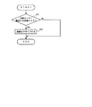
電子カメラ10とプリンター20とが直接接続され、操作部17を介してダイレクトプリントの対象となる画像が指定されると、ステップS1において、制御部16は、ダイレクトプリントの対象として、RAW画像が指定されたか否かを判定する。RAW画像が指定された場合はステップS2に進み、RAW画像が指定されない場合、すなわちJPEG画像が指定された場合はステップS3に進む。
When the electronic camera 10 and the
ステップS2において、制御部16は、ダイレクトプリントの対象として指定されたRAW画像を記録部14から読み出し、画像処理部12を介して、JPEG圧縮処理を行うことによりJPEG画像に変換する。
ステップS3において、制御部16は、ダイレクトプリントの対象として指定されたJPEG画像を記録部14から読み出してプリンター20に転送するか、または、ステップS2で変換したJPEG画像をプリンター20に転送する。
In step S <b> 2, the
In step S <b> 3, the
以上説明したように、第1実施形態によれば、電子カメラにより生成したデジタル形式のRAWデータを記録するとともに、そのRAWデータを画像出力装置が取り扱い可能なデータ形式(JPEG形式)に変換して、画像出力装置に転送する。そして、画像出力装置は、電子カメラから転送されたデータ形式変換後のRAWデータを受け取り、出力のための画像処理を行った後に画像として出力する。そのため、電子カメラの独自の形式であるRAW画像がユーザにより指定された場合でも、電子カメラ10が備える画像処理部12の機能を利用して、プリンター20が取り扱い可能なデータ形式であるJPEG形式に変換する。したがって、電子カメラと画像出力装置とからなる画像処理システムにおける操作性を向上することができる。また、電子カメラ10側でJPEG形式に変換してプリンター20に転送することにより、データ転送に要する時間の短縮も期待できる。
As described above, according to the first embodiment, the RAW data in the digital format generated by the electronic camera is recorded, and the RAW data is converted into a data format (JPEG format) that can be handled by the image output apparatus. And transfer to the image output device. The image output apparatus receives the RAW data after the data format conversion transferred from the electronic camera, performs image processing for output, and outputs it as an image. Therefore, even when a RAW image, which is a unique format of the electronic camera, is designated by the user, the function of the
<第2実施形態>
以下、本発明の第2実施形態について詳細に説明する。第2実施形態は、第1実施形態をより詳細にした実施形態である。
なお、以下では、第1実施形態と異なる部分についてのみ説明を行う。第2実施形態の画像処理システムは、第1実施形態の画像処理システム1と同様の構成を有する。以下では、第1実施形態と同様の符号を用いて説明する。
Second Embodiment
Hereinafter, the second embodiment of the present invention will be described in detail. The second embodiment is an embodiment in which the first embodiment is more detailed.
In the following, only the parts different from the first embodiment will be described. The image processing system of the second embodiment has the same configuration as the
第2実施形態では、第1実施形態と同様のダイレクトプリントに際して、2段階の指示が行われる。第1段階の指示とは、操作部17を介したユーザ操作に基づくダイレクトプリントの対象となる画像の指定であり、第2段階の指示とは、プリンター20側から電子カメラ10側への転送指示である。転送指示とは、プリンター20の制御部24から電子カメラ10の制御部16に対して行われる指示であり、電子カメラ10からプリンター20への画像の転送が可能で、かつ、受け入れ準備ができた状態で、プリンター20の制御部24から電子カメラ10の制御部16に対して行われる。
In the second embodiment, a two-step instruction is performed in the same direct printing as in the first embodiment. The first stage instruction is designation of an image to be directly printed based on a user operation via the
電子カメラ10とプリンター20とが直接接続されると、ステップS11において、制御部16は、操作部17を介してユーザによりダイレクトプリントの対象となる画像が指定されたか否かを判定する。制御部16は、画像が指定されるまで待機し、画像が指定されると、ステップS12に進む。
ステップS12において、制御部16は、ダイレクトプリントの対象として、RAW画像が指定されたか否かを判定する。RAW画像が指定された場合はステップS13に進み、RAW画像が指定されない場合、すなわちJPEG画像が指定された場合はステップS18に進む。
When the electronic camera 10 and the
In step S12, the
ステップS13において、制御部16は、ダイレクトプリントの対象として指定されたRAW画像を記録部14から読み出し、画像処理部12を介して、JPEG圧縮処理を行うことによりJPEG画像に変換する。
ステップS14において、制御部16は、ステップS13で変換したJPEG画像をメモリ18に記録する。すなわち、ステップS11において指定されたRAW画像をJPEG形式の仮想ファイルとしてメモリ18に用意しておく。
In step S <b> 13, the
In step S14, the
ステップS15において、制御部16は、外部インタフェース部15および外部インタフェース部21を介して、JPEG形式の名称をプリンター20の制御部24に通知する。このようにJPEG形式の名称を通知することにより、従来はプリンター20で取り扱い不可能であったRAW画像も取り扱い可能な画像として通知することができる。
ステップS16において、制御部16は、プリンター20から転送指示を受け付けたか否かを判定する。制御部16は、転送指示を受け付けるまで待機し、転送指示を受け付けるとステップS17に進む。なお、待機時間に上限を設け、上限を超えた場合にはステップS11に戻るようにしても良い。
In step S <b> 15, the
In step S <b> 16, the
ステップS17において、制御部16は、メモリ18に記録したJPEG画像(JPEG形式の仮想ファイル)を、外部インタフェース部15および外部インタフェース部21を介して、プリンター20に転送し、一連の処理を終了する。
一方、ステップS12でJPEG画像が指定された場合、ステップS18において、制御部16は、その画像の名称を外部インタフェース部15および外部インタフェース部21を介して、プリンター20の制御部24に通知する。
In step S17, the
On the other hand, when a JPEG image is designated in step S12, in step S18, the
ステップS19において、制御部16は、プリンター20から転送指示を受け付けたか否かを判定する。制御部16は、転送指示を受け付けるまで待機し、転送指示を受け付けるとステップS20に進む。なお、ステップS16と同様に、待機時間に上限を設け、上限を超えた場合にはステップS11に戻るようにしても良い。
ステップS20において、制御部16は、ステップS11で指定されたJPEG画像を記録部14から読み出して、外部インタフェース部15および外部インタフェース部21を介して、プリンター20に転送し、一連の処理を終了する。
In step S <b> 19, the
In step S20, the
以上説明したように、第2実施形態によれば、電子カメラに記録したRAWデータのうち、任意のRAWデータを指定するユーザ操作を受け付けると、そのRAWデータを電子カメラから画像出力装置へ転送する指示を受け付けるまでの間に、RAWデータを画像出力装置が取り扱い可能なデータ形式に変換する。したがって、ユーザ操作により指定されたRAW画像をJPEG形式の仮想ファイルとしてメモリ18に用意しておくことにより、プリンター20からの転送指示に素早く対応することができる。
As described above, according to the second embodiment, when a user operation for designating arbitrary RAW data among RAW data recorded in the electronic camera is received, the RAW data is transferred from the electronic camera to the image output device. Before the instruction is accepted, the RAW data is converted into a data format that can be handled by the image output apparatus. Accordingly, by preparing a RAW image designated by a user operation in the
<第3実施形態>
以下、本発明の第3実施形態について詳細に説明する。第3実施形態は、第2実施形態と同様に、第1実施形態をより詳細にした実施形態である。
なお、以下では、第1実施形態と異なる部分についてのみ説明を行う。第3実施形態の画像処理システムは、第1実施形態の画像処理システム1と同様の構成を有する。以下では、第1実施形態と同様の符号を用いて説明する。
<Third Embodiment>
Hereinafter, a third embodiment of the present invention will be described in detail. As in the second embodiment, the third embodiment is an embodiment in which the first embodiment is more detailed.
In the following, only the parts different from the first embodiment will be described. The image processing system of the third embodiment has the same configuration as the
第3実施形態では、第1実施形態と同様のダイレクトプリントに際して、第2実施形態と同様に、2段階の指示が行われる。第1段階の指示とは、操作部17を介したユーザ操作に基づくダイレクトプリントの対象となる画像の指定であり、第2段階の指示とは、プリンター20側から電子カメラ10側への転送指示である。転送指示とは、プリンター20の制御部24から電子カメラ10の制御部16に対して行われる指示であり、電子カメラ10からプリンター20への画像の転送が可能で、かつ、受け入れ準備ができた状態で、プリンター20の制御部24から電子カメラ10の制御部16に対して行われる。
In the third embodiment, in the same direct printing as in the first embodiment, a two-step instruction is performed as in the second embodiment. The first stage instruction is designation of an image to be directly printed based on a user operation via the
電子カメラ10とプリンター20とが直接接続されると、ステップS21において、制御部16は、操作部17を介してユーザによりダイレクトプリントの対象となる画像が指定されたか否かを判定する。制御部16は、画像が指定されるまで待機し、画像が指定されると、ステップS22に進む。
ステップS22において、制御部16は、ダイレクトプリントの対象として、RAW画像が指定されたか否かを判定する。RAW画像が指定された場合はステップS23に進み、RAW画像が指定されない場合、すなわちJPEG画像が指定された場合はステップS27に進む。
When the electronic camera 10 and the
In step S22, the
ステップS23において、制御部16は、RAW画像にJPEG形式の名称を付け、外部インタフェース部15および外部インタフェース部21を介して、プリンター20の制御部24に通知する。このようにJPEG形式の名称を通知することにより、従来はプリンター20で取り扱い不可能であったRAW画像も取り扱い可能な画像として通知することができる。
In step S <b> 23, the
ステップS24において、制御部16は、プリンター20から転送指示を受け付けたか否かを判定する。制御部16は、転送指示を受け付けるまで待機し、転送指示を受け付けるとステップS25に進む。なお、待機時間に上限を設け、上限を超えた場合にはステップS21に戻るようにしても良い。
ステップS25において、制御部16は、ステップS21で指定されたRAW画像を記録部14から読み出し、画像処理部12を介して、JPEG圧縮処理を行うことによりJPEG画像に変換する。
In step S <b> 24, the
In step S25, the
ステップS26において、制御部16は、ステップS25で変換したJPEG画像を、外部インタフェース部15および外部インタフェース部21を介して、プリンター20に転送し、一連の処理を終了する。
一方、ステップS22でJPEG画像が指定された場合、ステップS27において、制御部16は、その画像の名称を外部インタフェース部15および外部インタフェース部21を介して、プリンター20の制御部24に通知する。
In step S26, the
On the other hand, when a JPEG image is designated in step S22, in step S27, the
ステップS28において、制御部16は、プリンター20から転送指示を受け付けたか否かを判定する。制御部16は、転送指示を受け付けるまで待機し、転送指示を受け付けるとステップS20に進む。なお、ステップS24と同様に、待機時間に上限を設け、上限を超えた場合にはステップS21に戻るようにしても良い。
ステップS29において、制御部16は、ステップS22で指定されたJPEG画像を記録部14から読み出して、外部インタフェース部15および外部インタフェース部21を介して、プリンター20に転送し、一連の処理を終了する。
In step S <b> 28, the
In step S29, the
以上説明したように、第3実施形態によれば、電子カメラから画像出力装置へRAWデータを転送する指示を受け付けると、RAWデータを画像出力装置が取り扱い可能なデータ形式に変換する。そのため、電子カメラの独自の形式であるRAW画像がユーザにより指定された場合に、転送指示が行われると、電子カメラ10が備える画像処理部12の機能を利用して、プリンター20が取り扱い可能なデータ形式であるJPEG形式に変換しする。したがって、必要な場合にのみJPEG形式への変換を行うことができる。
As described above, according to the third embodiment, when an instruction to transfer RAW data from the electronic camera to the image output apparatus is received, the RAW data is converted into a data format that can be handled by the image output apparatus. Therefore, when a RAW image, which is a unique format of the electronic camera, is designated by the user, when a transfer instruction is issued, the
なお、上述した第1実施形態から第3実施形態の転送処理の前に、以下の処理を追加するようにしても良い。転送処理とは、第1実施形態では、図2のフローチャートのステップS3の処理であり、第2実施形態では、図3のフローチャートのステップS17またはステップS20の処理であり、第3実施形態では、図4のフローチャートのステップS26またはステップS29の処理である。 Note that the following processing may be added before the transfer processing of the first to third embodiments described above. In the first embodiment, the transfer process is the process of step S3 in the flowchart of FIG. 2, in the second embodiment, the process of step S17 or step S20 in the flowchart of FIG. 3, and in the third embodiment, This is the process of step S26 or step S29 in the flowchart of FIG.
ステップS31において、制御部16は、転送対象の画像サイズが、用紙サイズより大きいか否かを判定する。ここで、用紙サイズとは、プリンター20の画像出力部23において、用紙への印刷を行う際の用紙サイズであり、例えば、A4、A5などの形式で定められる。この用紙サイズは、操作部17を介したユーザ操作により指定される。制御部16は、転送対象の画像サイズが、用紙サイズより大きい場合にはステップS32に進み、転送対象の画像サイズが、用紙サイズより小さい場合には転送処理に移行する。
In step S31, the
ステップS32において、制御部16は、画像処理部12を介して、転送対象の画像を、用紙サイズに合わせてリサイズした後に転送処理に移行する。
例えば、A4の用紙サイズの用紙に、1枚の画像を出力する場合には、画像サイズは5M程度で十分である。また、A4の用紙サイズの用紙に、2枚の画像を出力する場合、および、A5の用紙サイズ(Lサイズ)の用紙に、1枚の画像を出力する場合には、画像のサイズは3M程度で十分である。制御部16は、用紙サイズごとに適当な画像サイズをテーブルとして記録しておき、転送処理の前に、画像処理部12を介してリサイズ処理を行う。
In step S <b> 32, the
For example, when outputting one image on a sheet of A4 paper size, an image size of about 5M is sufficient. In addition, when outputting two images on a sheet of A4 paper size and outputting one image on a sheet of A5 paper size (L size), the image size is about 3M. Is enough. The
このように、RAWデータを画像出力装置が取り扱い可能なデータ形式に変換するとともに、出力に適した画像サイズに基づいてリサイズ処理を行うことにより、必要以上にサイズの大きい画像サイズの画像を転送することによって無駄な転送時間が発生することを回避することができる。さらに、プリンターの動作中は、電子カメラは動作停止している場合が多く、機器間におけるパフォーマンスのバランスが悪い。そこで、プリンターの動作中に電子カメラ側でリサイズ処理を実行することにより、パフォーマンスのバランスを良くし、トータルのスループットを向上させることもできる。 In this way, the RAW data is converted into a data format that can be handled by the image output apparatus, and an image having an image size larger than necessary is transferred by performing resizing processing based on an image size suitable for output. As a result, it is possible to avoid generation of useless transfer time. Furthermore, the electronic camera is often stopped during the operation of the printer, and the performance balance between the devices is poor. Therefore, by executing the resizing process on the electronic camera side during the operation of the printer, it is possible to improve the balance of performance and improve the total throughput.
なお、このようなリサイズ処理は、転送対象の画像の形式にかかわらず実行すると良い。転送対象の画像がRAW画像である場合には、データのサイズを可能な限り縮小することにより、転送時間を大幅に短縮することが期待できる。
なお、上述した各実施形態では、画像出力装置の一例として、プリンターを例に挙げて説明を行ったが、ディスプレイ装置やプロジェクターなどの画像出力装置にも本発明を同様に適用することができる。
Such resizing processing is preferably executed regardless of the format of the image to be transferred. When the image to be transferred is a RAW image, it can be expected that the transfer time is greatly reduced by reducing the data size as much as possible.
In each of the above-described embodiments, a printer has been described as an example of an image output device. However, the present invention can be similarly applied to an image output device such as a display device or a projector.
また、上述した各実施形態では、画像出力装置が取り扱い可能なデータ形式としてJPEG形式を例に挙げて説明を行ったが、画像出力装置で取り扱うことが可能であれば、TIFF形式やBMP形式など他の形式であっても良い。
また、上述した各実施形態では、電子カメラ10の操作部17を介してユーザ操作を受け付ける例を示したが、プリンター20に操作部を設けて、適宜その操作部を介してユーザ操作を受け付けるようにしても良い。
In each of the above-described embodiments, the JPEG format has been described as an example of a data format that can be handled by the image output apparatus. However, if the image output apparatus can handle the data format, the TIFF format, the BMP format, or the like is used. Other formats may be used.
Moreover, although each embodiment mentioned above showed the example which receives user operation via the
また、上述した各実施形態を組み合わせて実行するようにしても良い。例えば、第2実施形態で説明した処理を行うモードと、第3実施形態で説明した処理を行うモードとを備え、ユーザ操作にしたがって、何れかの処理を実行するようにしても良い。 Moreover, you may make it perform combining each embodiment mentioned above. For example, a mode for performing the process described in the second embodiment and a mode for performing the process described in the third embodiment may be provided, and one of the processes may be executed according to a user operation.
1,画像処理システム 10,電子カメラ 11,撮像部 12・22,画像処理部 14,記録部 15・21,外部インタフェース部 16・24,制御部 17,操作部 18,メモリ 20,プリンター 23,画像出力部
1, image processing system 10,
Claims (5)
前記電子カメラは、
撮像素子により被写体像を撮像し、デジタル形式のRAWデータを出力する撮像部と、
前記撮像部により出力した前記RAWデータを記録する記録部と、
前記記録部から前記RAWデータを読み出して、前記画像出力装置が取り扱い可能なデータ形式に変換する変換部と、
前記変換部によりデータ形式を変換した前記RAWデータを、前記画像出力装置に転送する転送部とを備え、
前記画像出力装置は、
前記転送部により転送した前記RAWデータを受け取る受取部と、
前記受取部により受け取った前記RAWデータに、出力のための画像処理を行う画像処理部と、
前記画像処理部により画像処理を施した前記RAWデータを画像として出力する画像出力部とを備えた
ことを特徴とする画像処理システム。 An image processing system comprising an electronic camera and an image output device,
The electronic camera is
An imaging unit that captures a subject image with an image sensor and outputs RAW data in a digital format;
A recording unit for recording the RAW data output by the imaging unit;
A conversion unit that reads the raw data from the recording unit and converts the raw data into a data format that can be handled by the image output device;
A transfer unit that transfers the RAW data, the data format of which has been converted by the conversion unit, to the image output device;
The image output device includes:
A receiving unit for receiving the RAW data transferred by the transfer unit;
An image processing unit that performs image processing for output on the RAW data received by the receiving unit;
An image output system comprising: an image output unit that outputs the RAW data subjected to image processing by the image processing unit as an image.
前記変換部は、前記RAWデータを、JPEG形式に変換する
ことを特徴とする画像処理システム。 The image processing system according to claim 1,
The image processing system, wherein the conversion unit converts the RAW data into a JPEG format.
前記記録部に記録した前記RAWデータのうち、任意のRAWデータを指定するユーザ操作を受け付ける第1の受付部と、
前記任意のRAWデータを、前記電子カメラから前記画像出力装置へ転送する指示を受け付ける第2の受付部をさらに備え、
前記変換部は、前記第1の受付部により前記ユーザ操作を受け付けると、前記第2の受付部による受け付けまでの間に、前記RAWデータを前記画像出力装置が取り扱い可能なデータ形式に変換する
ことを特徴とする画像処理システム。 The image processing system according to claim 1,
A first receiving unit that receives a user operation for designating arbitrary RAW data among the RAW data recorded in the recording unit;
A second receiving unit that receives an instruction to transfer the arbitrary RAW data from the electronic camera to the image output device;
When the conversion unit receives the user operation by the first reception unit, the conversion unit converts the RAW data into a data format that can be handled by the image output apparatus before the reception by the second reception unit. An image processing system.
前記電子カメラから前記画像出力装置へ前記RAWデータを転送する指示を受け付ける受付部をさらに備え、
前記変換部は、前記受付部により前記指示を受け付けると、前記RAWデータを前記画像出力装置が取り扱い可能なデータ形式に変換する
ことを特徴とする画像処理システム。 The image processing system according to claim 1,
A reception unit that receives an instruction to transfer the RAW data from the electronic camera to the image output device;
The said conversion part will convert the said RAW data into the data format which the said image output device can handle, if the said instruction | indication is received by the said reception part. The image processing system characterized by the above-mentioned.
前記変換部は、前記RAWデータを、前記画像出力装置が取り扱い可能なデータ形式に変換するとともに、前記画像出力部による出力に適した画像サイズに基づいて、リサイズ処理を行う
ことを特徴とする画像処理システム。
The image processing system according to claim 1,
The conversion unit converts the RAW data into a data format that can be handled by the image output device, and performs a resizing process based on an image size suitable for output by the image output unit. Processing system.
Priority Applications (3)
| Application Number | Priority Date | Filing Date | Title |
|---|---|---|---|
| JP2005197830A JP2007019745A (en) | 2005-07-06 | 2005-07-06 | Image processing system |
| PCT/JP2006/313388 WO2007004669A1 (en) | 2005-07-06 | 2006-07-05 | Image processing system and electronic camera |
| US11/922,131 US8253808B2 (en) | 2005-07-06 | 2006-07-05 | Image processing system and electronic camera |
Applications Claiming Priority (1)
| Application Number | Priority Date | Filing Date | Title |
|---|---|---|---|
| JP2005197830A JP2007019745A (en) | 2005-07-06 | 2005-07-06 | Image processing system |
Publications (1)
| Publication Number | Publication Date |
|---|---|
| JP2007019745A true JP2007019745A (en) | 2007-01-25 |
Family
ID=37604528
Family Applications (1)
| Application Number | Title | Priority Date | Filing Date |
|---|---|---|---|
| JP2005197830A Withdrawn JP2007019745A (en) | 2005-07-06 | 2005-07-06 | Image processing system |
Country Status (3)
| Country | Link |
|---|---|
| US (1) | US8253808B2 (en) |
| JP (1) | JP2007019745A (en) |
| WO (1) | WO2007004669A1 (en) |
Cited By (4)
| Publication number | Priority date | Publication date | Assignee | Title |
|---|---|---|---|---|
| JP2008217422A (en) * | 2007-03-05 | 2008-09-18 | Seiko Epson Corp | Image processor |
| JP2009223376A (en) * | 2008-03-13 | 2009-10-01 | Seiko Epson Corp | Image processing apparatus and method of controlling the same |
| JP2009294834A (en) * | 2008-06-04 | 2009-12-17 | Nec Access Technica Ltd | Information processor, printer printing method, and program |
| CN109525795A (en) * | 2018-11-14 | 2019-03-26 | 武汉精立电子技术有限公司 | The method and apparatus for converting bmp picture for logic picture |
Families Citing this family (5)
| Publication number | Priority date | Publication date | Assignee | Title |
|---|---|---|---|---|
| JP5268960B2 (en) * | 2010-02-03 | 2013-08-21 | キヤノン株式会社 | Information processing apparatus, control method thereof, and program |
| JP2012209772A (en) * | 2011-03-30 | 2012-10-25 | Ricoh Co Ltd | Image processing apparatus, image formation apparatus, image processing method, image processing program, and recording medium |
| JP6412422B2 (en) * | 2014-12-11 | 2018-10-24 | キヤノン株式会社 | Image processing apparatus, control method therefor, system, and program |
| US10863158B2 (en) * | 2016-05-17 | 2020-12-08 | Canon Kabushiki Kaisha | Image processing apparatus, image processing method, and program |
| DE102018203969A1 (en) * | 2018-03-15 | 2019-09-19 | Conti Temic Microelectronic Gmbh | Automobile camera with raw image signal interface |
Family Cites Families (16)
| Publication number | Priority date | Publication date | Assignee | Title |
|---|---|---|---|---|
| JP3832089B2 (en) * | 1997-05-26 | 2006-10-11 | セイコーエプソン株式会社 | Digital camera and printing system |
| US6940541B1 (en) * | 1997-04-04 | 2005-09-06 | Eastman Kodak Company | Printer parameter compensation by a host camera |
| US6288743B1 (en) * | 1997-10-20 | 2001-09-11 | Eastman Kodak Company | Electronic camera for processing image segments |
| JP4463953B2 (en) | 2000-08-29 | 2010-05-19 | キヤノン株式会社 | Image processing system, digital camera and control method thereof |
| JP4416315B2 (en) * | 2000-12-21 | 2010-02-17 | キヤノン株式会社 | Imaging device and method for controlling imaging device |
| JP2003125330A (en) | 2001-10-16 | 2003-04-25 | Nikon Gijutsu Kobo:Kk | Picture storing system |
| US20030227554A1 (en) * | 2002-04-26 | 2003-12-11 | Nikon Corporation | Digital camera system |
| JP4027161B2 (en) * | 2002-06-04 | 2007-12-26 | キヤノン株式会社 | Printer apparatus and control method thereof |
| JP3885013B2 (en) | 2002-09-11 | 2007-02-21 | キヤノン株式会社 | IMAGING DEVICE, IMAGING DEVICE CONTROL METHOD, RECORDING MEDIUM THEREOF, AND PROGRAM THEREOF |
| DE60325678D1 (en) | 2002-09-11 | 2009-02-26 | Canon Kk | Data processing method and image pickup device |
| US20040095469A1 (en) * | 2002-11-18 | 2004-05-20 | Fu-Chang Lin | Digital camera capable of generating print data |
| JP2004221908A (en) * | 2003-01-14 | 2004-08-05 | Sanyo Electric Co Ltd | Method for controlling display, photographed image output sysetm capable of using the method, display control device, liquid crystal projector, and digital camera |
| JP4241228B2 (en) * | 2003-07-11 | 2009-03-18 | キヤノン株式会社 | Imaging device |
| JP2005354372A (en) | 2004-06-10 | 2005-12-22 | Olympus Corp | Apparatus and method for image recording device, method and system for image processing |
| JP4726239B2 (en) * | 2004-08-25 | 2011-07-20 | キヤノン株式会社 | Printing system, image supply device, printing apparatus and control method therefor |
| JP4560422B2 (en) * | 2005-02-16 | 2010-10-13 | キヤノン株式会社 | Imaging apparatus and control method thereof |
-
2005
- 2005-07-06 JP JP2005197830A patent/JP2007019745A/en not_active Withdrawn
-
2006
- 2006-07-05 WO PCT/JP2006/313388 patent/WO2007004669A1/en active Application Filing
- 2006-07-05 US US11/922,131 patent/US8253808B2/en not_active Expired - Fee Related
Cited By (4)
| Publication number | Priority date | Publication date | Assignee | Title |
|---|---|---|---|---|
| JP2008217422A (en) * | 2007-03-05 | 2008-09-18 | Seiko Epson Corp | Image processor |
| JP2009223376A (en) * | 2008-03-13 | 2009-10-01 | Seiko Epson Corp | Image processing apparatus and method of controlling the same |
| JP2009294834A (en) * | 2008-06-04 | 2009-12-17 | Nec Access Technica Ltd | Information processor, printer printing method, and program |
| CN109525795A (en) * | 2018-11-14 | 2019-03-26 | 武汉精立电子技术有限公司 | The method and apparatus for converting bmp picture for logic picture |
Also Published As
| Publication number | Publication date |
|---|---|
| WO2007004669A1 (en) | 2007-01-11 |
| US20090115853A1 (en) | 2009-05-07 |
| US8253808B2 (en) | 2012-08-28 |
Similar Documents
| Publication | Publication Date | Title |
|---|---|---|
| JP2007019745A (en) | Image processing system | |
| TWI239208B (en) | Image transmitting and receiving system, image transmitting device and receiving device | |
| JP2010021921A (en) | Electronic camera and image processing program | |
| EP1892664A1 (en) | Image processing device and method | |
| JP2006042004A (en) | Image processing unit and image processing method | |
| JP2006252206A (en) | Imaging device, information processor, and imaging system | |
| JP2007221685A (en) | Digital camera and control method therefor | |
| JP2008219738A (en) | Imaging apparatus | |
| WO2002041629A1 (en) | Image file generating device and digital still camera | |
| JP2007215001A (en) | Unit, system, and method for processing image | |
| JP2004254294A (en) | Active digital image capturing device | |
| JP2006319788A (en) | Image transfer system, image receiving device, image supply device, image transfer method, program, and storage medium | |
| JP2007081478A (en) | Printing system, imaging apparatus and control method thereof, printer, program and storage medium | |
| JP4873315B2 (en) | Image processing device | |
| JP4075948B2 (en) | Digital camera | |
| JP3832503B2 (en) | Digital camera and printing system | |
| JP2004260572A (en) | Digital camera and control method thereof | |
| JP4996316B2 (en) | Image processing apparatus, image processing method, image processing system, program, and storage medium | |
| JP2004264540A (en) | Image forming apparatus and image display method of image forming apparatus | |
| JP4306251B2 (en) | Information terminal with camera | |
| JP2006042035A (en) | Computer apparatus, image processing program and printing system | |
| JP2009223376A (en) | Image processing apparatus and method of controlling the same | |
| JP3649233B2 (en) | Digital camera and printing system | |
| JP4814737B2 (en) | Image processing apparatus, image processing method, and image processing program | |
| JP3864992B2 (en) | Digital camera and printing system |
Legal Events
| Date | Code | Title | Description |
|---|---|---|---|
| A300 | Application deemed to be withdrawn because no request for examination was validly filed |
Free format text: JAPANESE INTERMEDIATE CODE: A300 Effective date: 20081007 |