JP2007016997A - Slide module and mobile communication terminal equipped with the same - Google Patents
Slide module and mobile communication terminal equipped with the same Download PDFInfo
- Publication number
- JP2007016997A JP2007016997A JP2006189832A JP2006189832A JP2007016997A JP 2007016997 A JP2007016997 A JP 2007016997A JP 2006189832 A JP2006189832 A JP 2006189832A JP 2006189832 A JP2006189832 A JP 2006189832A JP 2007016997 A JP2007016997 A JP 2007016997A
- Authority
- JP
- Japan
- Prior art keywords
- slider
- base
- slide module
- rail
- friction
- Prior art date
- Legal status (The legal status is an assumption and is not a legal conclusion. Google has not performed a legal analysis and makes no representation as to the accuracy of the status listed.)
- Granted
Links
Images


Classifications
-
- H—ELECTRICITY
- H04—ELECTRIC COMMUNICATION TECHNIQUE
- H04M—TELEPHONIC COMMUNICATION
- H04M1/00—Substation equipment, e.g. for use by subscribers
- H04M1/02—Constructional features of telephone sets
- H04M1/0202—Portable telephone sets, e.g. cordless phones, mobile phones or bar type handsets
- H04M1/0206—Portable telephones comprising a plurality of mechanically joined movable body parts, e.g. hinged housings
- H04M1/0208—Portable telephones comprising a plurality of mechanically joined movable body parts, e.g. hinged housings characterized by the relative motions of the body parts
- H04M1/0235—Slidable or telescopic telephones, i.e. with a relative translation movement of the body parts; Telephones using a combination of translation and other relative motions of the body parts
- H04M1/0237—Sliding mechanism with one degree of freedom
Landscapes
- Engineering & Computer Science (AREA)
- Signal Processing (AREA)
- Telephone Set Structure (AREA)
- Bearings For Parts Moving Linearly (AREA)
- Sliding-Contact Bearings (AREA)
Abstract
Description
本発明は、スライドモジュール及びこれを備える移動通信端末機に関し、特に、スライドモジュールのスライド動作時に、相対移動する部材間の摩擦を低減して、より円滑かつ静粛なスライド動作を実現できるスライドモジュール及びこれを備える移動通信端末機に関する。 The present invention relates to a slide module and a mobile communication terminal including the slide module, and in particular, a slide module capable of realizing a smoother and quieter slide operation by reducing friction between members that move relatively during the slide operation of the slide module. The present invention relates to a mobile communication terminal equipped with this.
移動通信端末機(以下、端末機ともいう)は、携帯が可能な無線通信機器であって、そのボディのタイプによって、単一のボディで構成されるストレート型端末機、蓋部が本体部に対して開閉方向に回動可能に連結される折り畳み型端末機、スライダ部が本体部に対面した状態でスライドするスライド型端末機、回転部が本体部に対面した状態で回転(これもスライドの一種である)する回転型端末機などに分類される。 A mobile communication terminal (hereinafter also referred to as a terminal) is a wireless communication device that can be carried. Depending on the type of body, the mobile terminal is a straight-type terminal composed of a single body, and a lid is the main body. Folding-type terminal that is pivotably connected in the opening and closing direction, slide-type terminal that slides with the slider facing the main body, and rotation with the rotating part facing the main body (this is also a slide It is classified as a rotary terminal that is a type).
このような端末機において、2つ以上のボディ間の相対的な移動、すなわち、回動、スライド、又は回転を実現するためのモジュール(回動モジュール、スライドモジュール、又は回転モジュールなど)は、ユーザの操作による端末機のボディの機構的な相対位置の切替え(ボディの回動、スライド、又は回転などによって、例えば、使用時と不使用時とで端末機の形態を変化させること)を可能にする。 In such a terminal, a module (such as a rotation module, a slide module, or a rotation module) for realizing relative movement between two or more bodies, that is, rotation, slide, or rotation, is a user. It is possible to switch the mechanical relative position of the body of the terminal by operating (changing the form of the terminal between use and non-use, for example, by rotating, sliding, or rotating the body) To do.
ここで、回動モジュールは、1つのボディが他のボディに対して開閉方向に回動することを可能にする。また、スライドモジュールは、1つのボディが他のボディに対面した状態で該他のボディ上をスライドして移動することを可能にする。さらに、回転モジュールは、1つのボディが他のボディに対面した状態で該他のボディ上で回転することを可能にする。 Here, the rotation module enables one body to rotate in the opening / closing direction with respect to the other body. In addition, the slide module allows one body to slide and move on the other body while facing the other body. In addition, the rotation module allows one body to rotate on the other body while facing the other body.
ところで、このような端末機のボディの相対位置の切替え操作において、該相対位置の切替えのために設けられたモジュールの動作が円滑でなく、騒音や摩擦が発生するような場合は、ユーザの端末機に対する不満が大きくなる。 By the way, in such a switching operation of the relative position of the body of the terminal, if the operation of the module provided for switching the relative position is not smooth and noise and friction occur, the user terminal Dissatisfaction with the machine increases.
従って、端末機のボディの相対位置の切替え動作をより円滑かつ静粛に行うことのできるモジュールを提供することは重要であり、このようなモジュール及びこれを備える移動通信端末機が求められている。 Accordingly, it is important to provide a module that can perform the switching operation of the relative position of the body of the terminal more smoothly and quietly, and such a module and a mobile communication terminal including the module are required.
本発明は、このような実情に鑑みてなされたもので、そのスライド動作時に、相対移動する構成要素(部品)間の摩擦を低減し、より円滑かつ静粛なスライド動作を実現することのできるスライドモジュールを提供することを目的とする。 The present invention has been made in view of such circumstances, and at the time of the sliding operation, the sliding between the components (parts) that move relative to each other can be reduced, and a sliding operation that can realize a smoother and quieter sliding operation can be realized. The purpose is to provide modules.
本発明の他の目的は、前記スライドモジュールを備えるとともに、該スライドモジュールと端末機との結合を堅固にして、スライドによる端末機のボディの相対位置の切替え操作(形態変化)をより円滑かつ静粛に行うことのできる移動通信端末機を提供することにある。 Another object of the present invention is to provide the slide module, and to firmly connect the slide module and the terminal, so that the switching operation (form change) of the relative position of the body of the terminal by the slide is smoother and quieter. An object of the present invention is to provide a mobile communication terminal that can be used in the future.
上記目的を達成するために、本発明の一態様によるスライドモジュールは、ベースと、スライダと、摩擦低減部と、を含んで構成されることを特徴とする。 In order to achieve the above object, a slide module according to an aspect of the present invention includes a base, a slider, and a friction reduction unit.
ここで、前記ベースには、少なくとも1つのレール収容部が形成されており、好ましくは、このレール収容部は、前記ベースの両側(スライド方向に直交する方向の両側)に所定の長さを有して形成される。 Here, at least one rail housing portion is formed on the base, and preferably, the rail housing portion has a predetermined length on both sides of the base (both sides in a direction perpendicular to the sliding direction). Formed.
また、前記スライダには、前記レール収容部にスライド可能に収容されるレール部が形成されており、好ましくは、このレール部は、前記ベースの両側に形成されたレール収容部に対応するように前記スライダの両側に所定の長さを有して形成される。これにより、前記スライダは、前記ベースに対面した状態でレール収容部が延びる方向にスライド移動することができる。 The slider is formed with a rail portion slidably accommodated in the rail accommodating portion, and preferably, the rail portion corresponds to the rail accommodating portion formed on both sides of the base. A predetermined length is formed on both sides of the slider. As a result, the slider can slide in a direction in which the rail housing portion extends while facing the base.
さらに、前記摩擦低減部は、前記ベース及び前記スライダの少なくとも一方に形成されて、前記スライダが前記ベースからスライド移動する際に発生する摩擦を低減する。これにより、前記ベースと前記スライダとが相対的にスライド移動する時に発生する摩擦が低減されてより円滑なスライドが可能になり、スライド時の騒音も低減する。ここで、本発明における摩擦低減部は、その機能を有する部材を追加して構成する場合のほか、スライドモジュールを構成する各要素自体が所定の形状や特性を有することによってスライド時の摩擦を低減する場合も含む。 Furthermore, the friction reducing unit is formed on at least one of the base and the slider, and reduces friction generated when the slider slides from the base. As a result, the friction generated when the base and the slider slide relative to each other is reduced, enabling smoother sliding and reducing noise during sliding. Here, in addition to the case where the friction reducing unit in the present invention is configured by adding a member having the function, each element constituting the slide module itself has a predetermined shape and characteristics to reduce friction during sliding. This includes cases where
本発明の一実施形態に係るスライドモジュールにおいて、前記摩擦低減部は、潤滑性を有する物質がコーティングされて形成される摩擦低減コーティング層である。ここで、前記摩擦低減コーティング層は、前記ベース及び前記スライダの少なくとも一方の表面全体又は部分的にコーティングされて形成され、好ましくは、シリコーンがコーティングされて形成される。このようなシリコーンコーティング層は、スライド動作時に生じる前記ベースと前記スライダとの摩擦、さらには、これらに追加されるスライダの構成要素相互間の摩擦を緩和する。 In the slide module according to the embodiment of the present invention, the friction reducing portion is a friction reducing coating layer formed by coating a substance having lubricity. Here, the friction-reducing coating layer is formed by coating all or part of the surface of at least one of the base and the slider, and is preferably formed by coating silicone. Such a silicone coating layer alleviates the friction between the base and the slider, which occurs during the sliding operation, and the friction between the components of the slider added thereto.
本発明の他の実施形態に係るスライドモジュールにおいて、前記摩擦低減部は、前記レール収容部に前記レール部に接触するように装着されて、前記レール部と前記レール収容部との直接的な接触(摩擦)を緩和する摩擦低減部材である。この摩擦低減部材は、前記レール部と前記レール収容部との間の摩擦を緩和すると共に、その摩擦あるいは衝撃等に耐える耐久性を有しなければならない。このため、前記摩擦低減部材は、潤滑性を有すると共に機械的強度に優れたエンジニアリングプラスチック(例えば、POMなど)で形成されることが好ましい。 In the slide module according to another embodiment of the present invention, the friction reduction portion is mounted on the rail housing portion so as to contact the rail portion, so that the rail portion and the rail housing portion are in direct contact with each other. It is a friction reducing member that relieves (friction). The friction reducing member must have durability to withstand the friction or impact while reducing the friction between the rail portion and the rail housing portion. For this reason, it is preferable that the friction reducing member is formed of an engineering plastic (for example, POM) having lubricity and excellent mechanical strength.
また、前記摩擦低減部材を前記レール収容部に結合するために、前記摩擦低減部には、結合突起を形成し、前記レール収容部には、前記結合突起が挿入される突起収容孔を形成するようにしてもよい。さらに、前記摩擦低減部材と前記レール収容部とを別々に形成して事後的に結合するのではなく、前記レール収容部と共に二重射出して、あるいはアウトサート成形等により一体的に形成するようにしてもよい。 Further, in order to couple the friction reducing member to the rail housing part, a coupling protrusion is formed on the friction reducing part, and a protrusion housing hole into which the coupling protrusion is inserted is formed on the rail housing part. You may do it. Further, the friction reducing member and the rail housing portion are not separately formed and joined afterwards, but are formed integrally with the rail housing portion by double injection or by outsert molding or the like. It may be.
また、前記摩擦低減部材に加えて、該摩擦低減部材の長手方向(スライド方向)の両端部に装着される端部緩衝部材をさらに備えるようにしてもよい。この端部緩衝部材は、前記摩擦低減部材より衝撃吸収性に優れたゴムやウレタンなどで形成されるのが好ましく、前記スライダがスライドを停止する際に、前記レール収容部(又は前記摩擦低減部材)が他の部材と衝突することによって発生する衝撃を緩衝する(この場合、前記端部緩衝部材をストッパとして機能させてもよい)。ここで、前記他の部材は、前記スライドモジュールが装着される部材であり、例えば、スライダが装着される側の端末機本体が該当する。 Further, in addition to the friction reducing member, end cushioning members attached to both ends in the longitudinal direction (sliding direction) of the friction reducing member may be further provided. The end cushioning member is preferably formed of rubber, urethane, or the like having better shock absorption than the friction reducing member, and when the slider stops sliding, the rail accommodating portion (or the friction reducing member) ) Cushions an impact generated by collision with another member (in this case, the end cushioning member may function as a stopper). Here, the other member is a member to which the slide module is mounted, and corresponds to, for example, a terminal body on the side where the slider is mounted.
本発明のさらに他の実施形態に係るスライドモジュールにおいて、前記ベースと前記スライダとは異なる摩擦係数を有する材質で形成される。このように異なる摩擦係数を有する材質で形成された2つの部材の接触による摩擦は、これらが同じ材質で形成された場合より小さい。つまり、本実施形態は、別途の摩擦低減部を備えるのではなく、前記ベース及び前記スライダ自体の材質の選定により前記摩擦低減部としての機能を達成するものである。 In a slide module according to still another embodiment of the present invention, the base and the slider are formed of materials having different friction coefficients. Thus, the friction caused by the contact between the two members made of materials having different friction coefficients is smaller than when the two members are made of the same material. In other words, this embodiment does not include a separate friction reduction unit, but achieves the function as the friction reduction unit by selecting the material of the base and the slider itself.
本発明のさらに他の実施形態に係るスライドモジュールは、に前記スライダの前記ベースからのスライドを付勢する付勢部をさらに含む。 The slide module according to still another embodiment of the present invention further includes a biasing unit that biases the slide of the slider from the base.
ここで、前記付勢部は、前記ベースと前記スライダとの間に設置されるワイヤ状のスプリングを含む。このスプリングの表面に、該スプリングと前記ベースとの接触、該スプリングと前記スライダとの接触による摩擦を緩和するための摩擦低減コーティング層を形成してもよい。 Here, the urging portion includes a wire-like spring installed between the base and the slider. A friction reducing coating layer may be formed on the surface of the spring to reduce friction caused by contact between the spring and the base and contact between the spring and the slider.
さらに、前記スプリングは、その途中で前記スプリングの素材(ワイヤ状の部材)が前記ベース及び前記スライダの対向面とほぼ平行に閉曲線状に巻かれた巻き部を少なくとも2つ以上含む。このように巻き部が2つ以上形成されることによって、前記スプリングの付勢力がいずれか一方に集中しなくなるため、スプリング(巻き部)は、最初に配置されていた平面から離れずに動作する。従って、前記スプリングが浮き上がったり、下方に押し付けられたりすることが防止され、スプリングと前記ベースとの摩擦や前記スプリングと前記スライダとの摩擦が抑制される。これにより、前記スライダのスライド動作の円滑性及び静粛性が向上する。 Further, the spring includes at least two winding portions in which a spring material (wire-shaped member) is wound in a closed curve shape substantially parallel to the opposing surfaces of the base and the slider. By forming two or more winding portions in this way, the urging force of the spring does not concentrate on either one, so the spring (winding portion) operates without leaving the plane where it was originally placed. . Therefore, the spring is prevented from being lifted or pressed downward, and friction between the spring and the base and friction between the spring and the slider are suppressed. This improves the smoothness and quietness of the sliding operation of the slider.
また、前記巻き部が2回以上巻かれずに1回だけ巻かれることによって、前記スプリングは、その全体がほぼ同一平面に置かれることになる。1回だけ巻かれた巻き部は、2回以上巻かれた巻き部に比べて、その厚さが薄くなり、その前記ベース及び前記スライダの対向面に直交する方向への変動も小さくなる。これにより、1回だけ巻かれた巻き部を有するスプリングは、前記ベースや前記スライダとの接触が抑制されることとなり、該接触によって生じる摩擦も小さくなる。この結果、前記スライドモジュールの円滑なスライド動作を可能にする。つまり、付勢部の構成(より具体的には、スプリングの形状)によって、摩擦低減部としての機能を達成することもできるのである。また、スプリング全体としての厚さが薄くなることによって、前記スライドモジュール全体の厚さをより薄くすることができるという付加的な利点もある。 Further, when the winding portion is wound only once without being wound twice or more, the spring is entirely placed on the same plane. The winding portion wound only once is thinner than the winding portion wound twice or more, and the fluctuation in the direction perpendicular to the opposing surfaces of the base and the slider is also reduced. As a result, the spring having the winding portion wound only once is prevented from contacting the base and the slider, and friction caused by the contact is also reduced. As a result, the slide module can be smoothly slid. That is, the function as a friction reduction part can also be achieved by the configuration of the biasing part (more specifically, the shape of the spring). Further, since the thickness of the entire spring is reduced, there is an additional advantage that the thickness of the entire slide module can be further reduced.
また、前記付勢部が2つ設けられ、該一対の付勢部を対向配置して付勢時に両者の間で均衡をなすことによって、付勢部(スプリング)の前記ベース及び前記スライダの対向面に直交する方向への変動がさらに小さくなり、摩擦を減少させ、より安定したスライド動作を可能にする。なお、付勢部の対向配置の方法としては、スライド方向に対して所定角度を有して傾斜させた直線を中心として対抗配置させるのが好ましい。 Further, two urging portions are provided, and the pair of urging portions are arranged to face each other and balance between them at the time of urging, so that the base of the urging portion (spring) and the slider are opposed to each other. The variation in the direction perpendicular to the surface is further reduced, reducing friction and enabling more stable sliding motion. In addition, as a method of opposing arrangement | positioning of an urging | biasing part, it is preferable to carry out opposition arrangement | positioning centering | focusing on the straight line which inclined with a predetermined angle with respect to the sliding direction.
また、上記目的を達成するために、本発明に係るスライドモジュールを備える移動通信端末機は、第1本体と、第2本体と、前記第1本体と前記第2本体との間に設置され、前記第2本体を前記第1本体に対してスライド移動させるスライドモジュールとを含むことを特徴とする。 In order to achieve the above object, a mobile communication terminal including a slide module according to the present invention is installed between a first body, a second body, the first body, and the second body, And a slide module that slides the second body relative to the first body.
前記スライドモジュールは、前述したスライドモジュールのいずれかである。 The slide module is any of the slide modules described above.
また、本発明の他の態様に係るスライドモジュールを備える移動通信端末機は、前記スライドモジュールに加えて、前記スライダを前記第2本体に堅固に固定して、スライド動作時に、前記スライダの遊動及びそれによる摩擦をより効果的に緩和するための固定部をさらに含む。 According to another aspect of the present invention, there is provided a mobile communication terminal including a slide module, in which, in addition to the slide module, the slider is firmly fixed to the second main body. It further includes a fixing portion for more effectively mitigating the friction caused thereby.
本発明の一実施形態による移動通信端末機において、前記固定部は、前記スライダ及び前記第2本体のいずれか一方に形成される固定孔と、前記スライダ及び前記第2本体の他方に形成され、前記固定孔に挿入される固定突起とを含む。前記固定突起を、前記固定孔にスナップフィット式で結合されるように構成すれば、ネジなどを利用して前記スライダを前記第2本体に最終的に固定する前でも、所定レベルの固定力を簡単に提供することができると共に、前記最終的な固定の際の両者の位置決めを行えるという利点もある。 In the mobile communication terminal according to an embodiment of the present invention, the fixing part is formed in a fixing hole formed in one of the slider and the second body, and in the other of the slider and the second body, A fixing protrusion inserted into the fixing hole. If the fixing protrusion is configured to be coupled to the fixing hole by a snap-fit method, a predetermined level of fixing force can be applied even before the slider is finally fixed to the second body using a screw or the like. There is an advantage that both can be easily provided, and the positioning of the two during the final fixing can be performed.
本発明の他の実施形態による移動通信端末機において、前記固定部は、前記スライダ及び前記第2本体を、前記第2本体から前記スライダに向かう方向に締結する第1締結部と、その反対方向に締結する第2締結部とを含む。つまり、前記スライダの前記第2本体への締結を、スライダから第2本体へと向かう方向と第2本体からスライダへと向かう方向の両方向で行うことにより、締結力をより強化することができる。これにより、前記スライダが前記第2本体にさらに堅固に結合されて、その結合の不完全性による遊動、さらには、それによる摩擦の発生をより効果的に緩和できる。 In the mobile communication terminal according to another embodiment of the present invention, the fixed portion includes a first fastening portion that fastens the slider and the second body in a direction from the second body toward the slider, and the opposite direction. The 2nd fastening part fastened to. That is, the fastening force can be further strengthened by fastening the slider to the second main body in both the direction from the slider toward the second main body and the direction from the second main body toward the slider. As a result, the slider is more firmly coupled to the second main body, and it is possible to more effectively alleviate the looseness due to the imperfection of the coupling, and the generation of friction caused thereby.
本発明に係るスライドモジュールは、摩擦低減部を備えることにより、ベースとスライダの相対的なスライド時に発生する摩擦を低減して、スライド動作をより円滑にし、スライド動作に伴う騒音も低減することができる。 The slide module according to the present invention includes a friction reduction unit, so that the friction generated when the base and the slider slide relative to each other can be reduced, the sliding operation can be performed more smoothly, and the noise accompanying the sliding operation can be reduced. it can.
ここで、前記摩擦低減部は別途の部材で形成されてもよいが、スライドモジュール自体の構成で形成することにより、スライド動作時の摩擦を低減できるスライドモジュールの生産が容易になる。例えば、摩擦低減部として、スライドモジュールのベース及びスライダの少なくとも一方の表面(の全体又は部分的に)にシリコーン等の摩擦低減コーティング層を形成したり、ベース側のレール収容部に、スライダ側のレールがスライド可能に挿入されるレール溝を有する摩擦低減部材(例えばPOM製)を装着したりすれば、ベース側のレール収容部とスライダ側のレールとが直接接触することなく、摩擦低減部材を介することになってスライド動作時の摩擦を効果的に低減することができる。また、スライドモジュールの構成要素の形状や特性を適切に選定することで摩擦低減部としての機能を持たせ、これにより、スライド動作時の摩擦を効果的に防止することができる。 Here, the friction reducing unit may be formed of a separate member. However, by forming the friction reducing unit with the configuration of the slide module itself, the production of the slide module capable of reducing the friction during the sliding operation is facilitated. For example, as a friction reducing portion, a friction reducing coating layer such as silicone is formed on at least one surface (entirely or partially) of the base of the slide module and the slider. If a friction reducing member (for example, made of POM) having a rail groove into which the rail is slidably inserted is mounted, the friction reducing member can be mounted without directly contacting the rail housing portion on the base side and the rail on the slider side. Therefore, the friction during the sliding operation can be effectively reduced. In addition, by appropriately selecting the shape and characteristics of the constituent elements of the slide module, it is possible to provide a function as a friction reducing unit, thereby effectively preventing friction during the sliding operation.
また、本発明に係る移動通信端末機は、前記スライドモジュールを備えることにより、そのスライド動作を円滑かつ静粛に行えるという効果がある。 In addition, the mobile communication terminal according to the present invention includes the slide module, so that the sliding operation can be performed smoothly and quietly.
以下、添付の図面を参照して、本発明に係るスライドモジュール及びこれを備える移動通信端末機の好ましい実施形態を説明する。 Hereinafter, preferred embodiments of a slide module according to the present invention and a mobile communication terminal including the same will be described with reference to the accompanying drawings.
図1は本発明の一実施形態に係るスライドモジュールを備える移動通信端末機の分解斜視図である。 FIG. 1 is an exploded perspective view of a mobile communication terminal including a slide module according to an embodiment of the present invention.
図1に示すように、本発明の一態様による移動通信端末機は、第1本体100と、第2本体200と、第2本体200を第1本体100に対して相対的にスライド移動させるスライドモジュール300と、を含んで構成される。
As shown in FIG. 1, a mobile communication terminal according to an aspect of the present invention includes a first
第1本体100は、所定の内部空間を形成するように上部カバー101と下部カバー102とが結合されて形成される。内部空間には、移動通信端末機の各部品を電気的に制御するプリント基板(図示せず)が内蔵される。上部カバー101の主面(表面)の一方の側(移動通信端末機の使用時に下となる側であり、以下、単に「下側」という)には、数字や文字などを入力するための入力ユニット、例えば、複数のキーボタン110が配列される。また、キーボタン110のさらに下側には、音を入力するためのマイク120が備えられる。下部カバー102には、移動通信端末機に電源を供給するバッテリ130が着脱可能に結合される。また、上部カバー101の他方の側(すなわち、上側)には、前記主面よりもやや低い(主面から凹んだ)ベース設置部140が形成される。このベース設置部140には、少なくとも1つの締結孔141が設けられる。
The first
第2本体200も、所定の内部空間を形成するように上部カバー201と下部カバー202とが結合されて形成される。内部空間には、視覚情報を出力するためのLCDなどのディスプレイモジュール(図示せず)が内蔵される。上部カバー201のほぼ中央(又は中央からやや上側)には、前記ディスプレイモジュールから出力される視覚情報を外部から見ることができるようにウィンドウ210が形成される。また、ウィンドウ210の下側には、移動通信端末機の各機能を実行する際に使用するファンクションキー220が配列されており、ウィンドウ210のさらに上側には、音を出力するためのスピーカ230が備えられる。
The second
スライドモジュール300は、第1本体100と第2本体200との間に設置されて、これらの相対的なスライド移動を可能にする。スライドモジュール300は、ベース310と、ベース310にスライド可能に結合されるスライダ320とを含んで構成される。
The
ベース310は、第1本体100に結合される。ベース310の第1本体100への結合は、例えば、ベース310を上部カバー101のベース設置部140に位置させて、ベース315の締結孔(貫通孔)315(図2)及びベース設置部140の締結孔(ネジ孔)141を利用したネジ止めにより行う。
The
一方、スライダ320は、第2本体200に結合される。スライダ320の第2本体200への結合は、例えば、スライダ320の締結孔(貫通孔)322及び第2本体200の締結孔(ネジ孔、図示せず)を利用したネジ止めにより行う。
そして、本実施形態における移動通信端末機は、通常時(待機時等)は、第2本体200が第1本体100上に重なるように位置しており、第2本体200を第1本体100から(上方に)スライドさせることにより、入力ユニット(キーボタン110)が露出するように構成されている。
Meanwhile, the
The mobile communication terminal according to the present embodiment is positioned so that the second
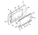
図2は、図1のスライドモジュールを上下反転させた状態を示す斜視図、図3は、図2のスライドモジュールの分解斜視図、図4は、図2のX−X断面図である。 2 is a perspective view showing a state in which the slide module of FIG. 1 is turned upside down, FIG. 3 is an exploded perspective view of the slide module of FIG. 2, and FIG. 4 is a sectional view taken along line XX of FIG.
図2及び図3に示すように、ベース310は、少なくとも1つのレール収容部311を含む。好ましくは、レール収容部311は、ベース310の長手方向(スライド方向)に沿って、ベース310の短手方向(スライド方向に直交する方向)の両側縁部に形成される。ここでは、ベース310の両側縁部を2回屈曲させてレール収容部311を形成している(但し、これは一例であり、他の方法でレール収容部311を形成してもよい)。
As shown in FIGS. 2 and 3, the
また、スライダ320は、レール収容部311に対応して少なくとも1つのレール部321を含む。ここでは、スライダ320の両側縁部を2回屈曲してレール部321が形成されており、このレール部321がレール収容部311にスライド可能に挿入される(但し、これも一例であり、他の方法でレール部321を形成してもよい)。
The
また、スライドモジュール300は、スライダ320をベース310から離れる方向にスライド移動させるように付勢する付勢部330をさらに含んでいる。この付勢部330は、ベース310及びスライダ320の互いに対向する面(以下、単に「対向面」という)の間に設置され、ワイヤ状の付勢部材(スプリング)を含む。
The
ここで、スライドモジュール300は、スライド動作時に、ベース310とスライダ320との間、ベース310と付勢部330との間、及び/又は、スライダ320と付勢部330との間の摩擦を低減して、スライドモジュール300の円滑かつ静粛なスライド動作を可能にするよう、摩擦低減部をさらに含んでいる。
Here, the
本発明の第1実施形態に係るスライドモジュールにおいては、スライダ320の表面に形成される摩擦低減コーティング層340が前記摩擦低減部に相当する。この摩擦低減コーティング層340は、潤滑性を有する材料をコーティングして形成したもので、潤滑性を有する材料としてはシリコーンなどを使用できる。なお、摩擦低減コーティング層340は、スライダ320の表面全体に形成される場合のほか、必要な箇所に部分的に形成する場合も含む。
In the slide module according to the first embodiment of the present invention, the friction reducing
このような摩擦低減コーティング層340により、ベース310のレール収容部311と、該レール収容部311に収容されるスライダ320のレール部321との直接的な摩擦が緩和される。
By such a friction reducing
また、図4からも分かるように、摩擦低減コーティング層340により、スライダ320と付勢部330のスプリング333との直接的な摩擦も緩和される。さらに、ベース310の表面にもスライダ320と同様に摩擦低減コーティング層340を形成することにより(全体に又は部分的に)、ベース310とスプリング333との摩擦を緩和することもできる。さらに、スプリング333の表面をシリコーンなどでコーティング処理することにより、スプリング333とベース310との摩擦、スプリング333とスライダ320との摩擦をさらに効果的に緩和できる。
As can be seen from FIG. 4, the friction reducing
このように、摩擦低減コーティング層340を、ベース310、スライダ320及び/又はスプリング333に形成することにより、ベース310とスライダ320との間、ベース310と付勢部330との間、スライダ320と付勢部330との間の摩擦が緩和され、これによって、スライドモジュール300は、より円滑かつ静粛にスライド動作を達成できる。
In this manner, the friction reducing
次に、本発明の第2実施形態に係るスライドモジュールを説明する。第2実施形態に係るスライドモジュールにおいては、ベース310のレール収容部311に装着される摩擦低減部材350が前記摩擦低減部に相当する。
Next, the slide module which concerns on 2nd Embodiment of this invention is demonstrated. In the slide module according to the second embodiment, the
図3を参照すると、摩擦低減部材350は、長手方向に延びる棒状の部材であり、レール収容部311に長手方向に沿って挿入されて装着される。また、摩擦低減部材350には、長手方向に沿ってレール溝353が形成されており、このレール溝353にスライダ320のレール部321がスライド可能に挿入される。これにより、摩擦低減部材350は、レール部321のスライド移動を所定の高さでガイドする。
Referring to FIG. 3, the
このような摩擦低減部材350は、ベース310のレール収容部311とスライダ320のレール部321との間の摩擦を低減するために挿入されるもので、それ自体が潤滑性を有すると共に、摩擦による衝撃等にも耐えるように所定レベルの強度を有する素材であるものが好ましい。このため、摩擦低減部材350としては、潤滑性及び所定レベルの強度を有するエンジニアリングプラスチックを使用するのが好ましい。エンジニアリングプラスチックは、その種類が多様であるが、前述した2つの特性を考慮すると、例えば、ポリアセタール樹脂(POM)を使用することが好ましい。
Such a
また、摩擦低減部材350をレール収容部311に結合(固定)する方式は多様であるが、その1つの結合方式として、摩擦低減部材350から突出形成される結合突起351と、この結合突起351に対応してレール収容部311に形成され、結合突起351が挿入される突起収容孔312とを含む結合部を設けることができる。この結合部により、摩擦低減部材350は、レール収容部311内で位置決め固定され、レール収容部311の長手方向に沿って遊動せずに堅固に固定される。他の結合方式として、摩擦低減部材350をベース310(具体的には、レール収容部311)と共に二重射出して(あるいは、アウトサート成形により)、別途の結合をせずに、摩擦低減部材350とベース310(具体的には、レール収容部311)とを一体的に形成することができる。この場合も、突起収容孔312をレール収容部311に予め形成しておくことにより、摩擦低減部材350とレール収容部311との結合を堅固に維持できる。
There are various methods for coupling (fixing) the
図4を参照すると、摩擦低減部材350によって、ベース310のレール収容部311とスライダ320のレール部321との直接的な摩擦は、潤滑性のある摩擦低減部材350を介した間接的な摩擦に変換される。これにより、ベース310のレール収容部311とスライダ320のレール部321との摩擦が緩和され、スライドモジュール300は、より円滑かつ静粛なスライド動作を達成できる。
Referring to FIG. 4, the
また、摩擦低減部材350の長手方向の両端部には、スライダ320がスライドを停止する際に、他の部材、例えば、第2本体200(図1参照)と、ベース310(具体的には、レール収容部311又は摩擦低減部材350)との衝突を緩和するための端部緩衝部材360をさらに装着してもよい。
Further, at both ends in the longitudinal direction of the
端部緩衝部材360は、摩擦低減部材350よりは軟らかくて衝撃吸収性に優れたゴムやウレタンなどの素材で形成されることが好ましい。
The
また、端部緩衝部材360を摩擦低減部材350に結合するための端部結合部は、摩擦低減部材350の両端部の切欠部分352に形成された端部突起352aと、端部緩衝部材360の延長部361に形成された端部孔361aとから構成される。つまり、端部緩衝部材360の端部孔361aに摩擦低減部材350の端部突起352aが挿入されることによって、端部緩衝部材360が摩擦低減部材350に結合される。ここで、レール収容部311の長手方向の両端部には、端部緩衝部材360を収容する収容部313が切欠形成されている。なお、端部緩衝部材360は、ベース310(レール収容部311)の両端部よりもやや突出した状態で収容部360に収容される。
In addition, the end coupling portion for coupling the
次に、本発明の第3実施形態に係るスライドモジュールを説明する。第3実施形態に係るスライドモジュールにおいて、前記摩擦低減部は、付勢部330自体の構成により実現される。
Next, a slide module according to a third embodiment of the present invention will be described. In the slide module according to the third embodiment, the friction reduction unit is realized by the configuration of the
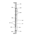
図2及び図3を参照すると、付勢部330は、対向面であるベース310及びスライダ320の主面のそれぞれから突出形成される支持部(ボス)331、332と、スプリング333と、を含んで構成され、スプリング333の両端部は、支持部331、332にそれぞれ支持される。
Referring to FIGS. 2 and 3, the urging
スプリング333は、ワイヤ状のスプリングであって、その途中で閉曲線状、例えば、円形に巻かれて付勢力を蓄積する巻き部333aと、両端部で支持部331、332に結合されて支持されるために円形に巻かれたフック部333bとを含む。ここで、巻き部333a、フック部333bは、それぞれベース310及びスライダ320の対向面とほぼ平行に閉曲線状、円形に巻回して形成されている。
The
ここで、巻き部333aは、少なくとも2つ以上形成される。2つ以上の巻き部333aは、相互補完する役割を果たして、いずれか一方に相対的に大きな力が集中しても、その一方の位置がベース310又はスライダ320側に偏らない。つまり、2つ以上の巻き部333aを形成することにより相互間の力の均衡がとれ、これらが最初に配置された平面上で動作することが可能となる(すなわち、動作中に大きく浮いてしまったり、下方に押し付けられたりすることを防止できる)。その結果、巻き部333aがベース310又はスライダ320側に偏ることによって生じる摩擦が可能な限り防止される。
Here, at least two winding
また、それぞれの巻き部333aは、ワイヤを閉曲線状に1回だけ巻かれて形成されることが好ましい。2回以上巻かれた巻き部、すなわち二重巻き以上の巻き部333aを有するスプリングは、巻き部が多層をなして、スプリングの動作時に、ベース310及びスライダ320の主面(対向面)に垂直な方向(図4におけるH方向)の変動が大きくなってしまう。これに対して、本実施形態のように、1回だけ巻かれた巻き部333aを有するスプリング333は、そのような変動が小さい(ほとんどない)ため、スプリング333とベース310又はスライダ320の主面との間に生じる摩擦がほとんどない(極めて小さい)。また、1回だけ巻かれた巻き部333aを有するスプリング333は、その厚さが薄いため(H方向の寸法が小さいため)、本発明に係るスライドモジュール300全体を薄くすることができるという追加的な利点をも提供する。
Each winding
また、付勢部330は、対向して配列されるように一対備えられる(図5参照)。この場合、付勢部330は、スライダ320のスライド方向に対して所定角度だけ傾斜した線(中心線)Cを中心として対向配置されるのが好ましい。このような配列(配置)は、動作時に、付勢部330(スプリング333)がベース310又はスライダ320のいずれか一方に偏らないようにして、ベース310及びスライダ320との摩擦を低減する。なお、変形して付勢力を蓄積する巻き部333aは、少なくとも1つ形成されればよいが、上述したように、2つ又はそれ以上形成されることが有利である。
Further, a pair of urging
図4を参照すると、付勢部330は、1回だけ巻かれた巻き部333aを2つ有するスプリング333を備えることにより、前記H方向への変動を少なくすることができ、ベース310及びスライダ320との摩擦が緩和される。また、一対の付勢部330が、その外側を結ぶ線がほぼ六角形となるように配列することによって、付勢部330がベース310又はスライダ320のいずれか一方に偏って摩擦が増加してしまうことも防止される。このように、スプリング333自体の構成(形状)によって、付勢部330(スプリング333)とベース310との間、付勢部330(スプリング333)とスライダ320との間の摩擦を低減(摩擦の発生を防止)する(すなわち、摩擦低減部として機能させる)ことで、前記第1及び第2実施形態のように、別途の摩擦低減コーティング層340又は摩擦低減部材350を備えなくてもよい、という利点がある。
Referring to FIG. 4, the biasing
次に、本発明の第4実施形態に係るスライドモジュールを説明する。第4実施形態に係るスライドモジュールにおいて、前記摩擦低減部の機能は、ベース310とスライダ320とが異なる摩擦係数を有することにより達成される。
Next, a slide module according to a fourth embodiment of the present invention will be described. In the slide module according to the fourth embodiment, the function of the friction reduction unit is achieved by the fact that the
一般に、接触する2つの部材間の摩擦は、2つの部材の摩擦係数が異なる場合の方が同じ場合よりも小さい。このような原理を利用して、ベース310とスライダ320とを異なる材質で形成して、両者の摩擦係数が異なるようにする。これにより、ベース310とスライダ320との摩擦は低減し、それによる作動騒音も低減する。
Generally, the friction between two members in contact with each other is smaller when the friction coefficients of the two members are different than when the same. Utilizing such a principle, the
このような第4実施形態は、前記第1及び第2実施形態に係る摩擦低減部とは異なり、摩擦低減コーティング層340又は摩擦低減部材350などの追加的な構成を必要としない点で、前記第3実施形態と同様の利点がある。なお、これ以外にも、ベース310及び/又はスライダ320の一部又は全体に、別部材を貼付したりすることによって、両者の摺動部分における摩擦係数を異なるようにしてもよいことはもちろんである。
Unlike the friction reducing unit according to the first and second embodiments, the fourth embodiment does not require an additional configuration such as the friction reducing
図5及び図6は、スライドによるベース310とスライダ320との相対的な位置関係を説明するための図であり、図5は、スライダ320がベース310から図の上側に移動した状態を示し、図6は、スライダ320がベース310から図の下側に移動した状態を示す。
このように、本実施形態に係るスライドモジュールは、スライダ320が、ベース310に対して上下方向にスライド移動することが可能であるが、端末機に取り付けられた場合には、いずれか一方の方向にのみ移動するのが通常である。これは、前述したように、端末機においては、通常時(待機時等)は、第2本体200が第1本体100上に重なるように位置しており、使用時に第2本体200を第1本体100から上方に(又は下方に)スライドさせることにより、入力ユニット(キーボタン110)が露出するようにするためである。この場合、通常時(待機時等)にスプリング333が弾性変形し(付勢力を蓄積し)、その状態を図示しないラッチ機構等で保持するようにし、該ラッチ機構を解除することでスプリング333の付勢力によって第2本体200がスライド移動することになる。また、所定の位置までスライドしたときに、及び/又は、スライドしたスライダ320を通常時(待機時等)の位置まで戻すときに、例えば、第2本体200の一部を端部緩衝部材360に当接させるようにて、第2本体200のそれ以上のスライドを禁止するようにしてもよい。
5 and 6 are diagrams for explaining the relative positional relationship between the base 310 and the
As described above, in the slide module according to the present embodiment, the
ベース310とスライダ320とのスライド動作時、すなわち、図5又は図6の状態への切換え時に、以上説明した実施形態に係る摩擦低減部(摩擦低減コーティング層340、摩擦低減部材350、付勢部330自体の構成、ベース310とスライダ320自体の選択された材質)のうちのいずれか1つ又はこれらの複合的な作用によってスライド動作時の摩擦が低減して、スライド動作がより円滑かつ静粛に行われる。
During the sliding operation of the
以下、移動通信端末機において、スライドモジュールと第2本体の結合関係に関連して、前述した摩擦低減部の機能をより効果的に達成するための構成について説明する。 Hereinafter, in the mobile communication terminal, a configuration for more effectively achieving the above-described function of the friction reduction unit will be described in relation to the coupling relationship between the slide module and the second body.
図7は、図1の移動通信端末機の第2本体とスライダとの結合方式を説明するための分解斜視図、図8は、図7の結合状態を説明するための側面図である。なお、図7及び図8においては、すでに説明した図面と同一構成については、同一の符号を使用するか、あるいは、その図示を省略する。 FIG. 7 is an exploded perspective view for explaining a coupling method between the second main body and the slider of the mobile communication terminal of FIG. 1, and FIG. 8 is a side view for explaining the coupling state of FIG. 7 and 8, the same reference numerals are used for the same components as those already described, or the illustration thereof is omitted.
図7及び図8に示すように、第2本体200(図1参照)の下部カバー202には、スライダ320′を設置するためのスライダ設置部202aが形成される。スライダ設置部202aは、スライダ320′を収容するために、下部カバー202の他の部分より低く(凹んで)形成される。また、スライダ設置部202aには、開口部202eが、スライダ320′には、切欠部320′dがそれぞれ形成されて、第1本体100(図2参照)と第2本体200との間の信号ケーブル(図示せず)による接続を可能にする。
As shown in FIGS. 7 and 8, the
ここで、下部カバー202とスライダ320′との完全な結合によって、スライダ320′が第2本体200(具体的には、下部カバー202)から離隔しないようにすると、スライドモジュール200の動作時に、スライダ320′と下部カバー202との衝突(又は、摩擦)が発生しない。このために、本実施形態では、スライダ320′と下部カバー202との間での離隔を防止するように固定部を形成している。
Here, when the
本実施形態に係る移動通信端末機において、そのような固定部は、スライダ320′の長手方向の両端部から突出形成される固定突起320′cと、該固定突起320′cに対応して下部カバー202に形成される固定孔202bと、から構成される。固定突起320′c及び固定孔202bは、スライダ320′及び下部カバー202の長手方向のいずれか一方の端部に形成するようにしてもよいが、両端部に形成することが好ましい。これは、前記長手方向の両端部でスライダ320′と下部カバー202との離隔が発生する可能性が相対的に高いためである。
In the mobile communication terminal according to the present embodiment, such a fixed part includes a fixed protrusion 320'c that protrudes from both ends in the longitudinal direction of the slider 320 ', and a lower part corresponding to the fixed protrusion 320'c. And a fixing
本実施形態においては、スライダ320′をスライダ設置部202a側に加圧することにより、固定突起320′cが固定孔202bに入り込む、いわゆるスナップフィット式の結合が簡単に行われるようになっている。
In this embodiment, by pressing the
このようなスライダ320′と下部カバー202との結合方式は、スライダ320′が下部カバー202から離隔しないようにし、かつその結合方法も非常に簡単である。これにより、スライドモジュール300のスライド動作時に、スライダ320′が下部カバー202に完全に固定されていないことから発生する、スライダ320′と下部カバー202との衝突、摩擦並びに騒音などが抑制(緩和)され、スライドモジュール300の円滑かつ静粛な動作が可能になる。また、簡単なスナップフィット式の結合方式のスライダ320′と下部カバー202との1次結合によって、ネジなどを利用してより確実な固定を行うための2次結合時に、スライダ320′と下部カバー202間との位置合わせが不要になるという追加的な利点もある。
Such a coupling method of the
他の実施形態による移動通信端末機において、前記固定部は、下部カバー202及びスライダ320′を、下部カバー202側からスライダ320′に向かう方向に締結する第1締結部と、該第1締結部と反対方向に締結する第2締結部とから構成される。
In the mobile communication terminal according to another embodiment, the fixing portion includes a first fastening portion that fastens the
前記第1締結部は、下部カバー202及びスライダ320′のそれぞれに形成される第1締結孔202c、320′aと、下部カバー202からスライダ320′の方向に第1締結孔202c、320´aに挿入されて下部カバー202とスライダ320′とを締結し、固定するネジなどの第1締結手段410と、を含む。
The first fastening portion includes first fastening holes 202c and 320'a formed in the
また、前記第2締結部は、下部カバー202及びスライダ320′のそれぞれに形成される第2締結孔202d、320′bと、スライダ320′から下部カバー202の方向に第2締結孔202d、320´bに挿入されて下部カバー202とスライダ320′とを締結し、固定するネジなどの第2締結手段420と、を含む。
The second fastening portion includes
これら第1締結部及び前記第2締結部が、下部カバー202とスライダ320′とを反対方向から締結し、固定することによって、同一方向から締結した場合より、下部カバー202とスライダ320′との結合がより堅固に、しかも長期間維持されることになる。これにより、スライダ320′が下部カバー202に完全に固定されることとなり、スライド動作時におけるスライドモジュール300の円滑かつ静粛な動作が可能になる。
The first fastening portion and the second fastening portion fasten the
以上、本発明の実施形態に係るスライドモジュール及びこれを備える移動通信端末機を添付の図面を参照して説明したが、本発明は、本明細書に開示された実施形態と図面により限定されるものではなく、本発明の技術思想の範囲内で当業者により多様に変形可能である。 The slide module and the mobile communication terminal including the slide module according to the embodiment of the present invention have been described with reference to the accompanying drawings. However, the present invention is limited by the embodiment and the drawings disclosed in the present specification. However, various modifications can be made by those skilled in the art within the scope of the technical idea of the present invention.
例えば、本明細書では、ベース310にレール収容部311が形成され、スライダ320、320′にレール部321が形成される場合を説明したが、その反対に形成することもできる。また、本明細書では、ベース310が第1本体100に結合され、スライダ320、320′が第2本体200に結合される場合を説明したが、その反対に結合することもできる。
For example, in the present specification, the case where the
さらに、本明細書では、本発明をスライド型端末機に基づいて説明したが、回転型端末機にも適用できる。これは、スライド型端末機と回転型端末機とは、1つのボディが、他のボディに対面した状態で、該他のボディに対してスライド移動する点という点で類似するためである。但し、スライド型端末機は直線状にスライド移動するのに対し、回転型端末機は円弧状のスライド軌跡を有する点が異なる。つまり、本発明における「スライド」とは、直線状を移動する場合のほか、円弧状を移動する場合も含むものである。 Further, in the present specification, the present invention has been described based on the slide type terminal, but it can also be applied to a rotary type terminal. This is because the slide-type terminal and the rotary-type terminal are similar in that one body slides with respect to the other body while facing the other body. However, the slide type terminal slides linearly, whereas the rotary type terminal has a circular slide trajectory. That is, the “slide” in the present invention includes not only the case of moving in a straight line but also the case of moving in an arc.
100 第1本体
200 第2本体
300 スライドモジュール
310 ベース
320 スライダ
330 付勢部
340 摩擦低減コーティング層
350 摩擦低減部材
360 端部緩衝部材
DESCRIPTION OF
Claims (20)
前記レール収容部にスライド可能に収容されるレール部が形成され、前記ベースに対向して配置されるスライダと、
前記ベース及び前記スライダの少なくとも一方に形成され、前記スライダが前記ベースからスライド移動する際に発生する摩擦を低減する摩擦低減部と、
を含んで構成されることを特徴とするスライドモジュール。 A base on which at least one rail housing is formed;
A rail portion slidably accommodated in the rail accommodating portion, and a slider disposed to face the base;
A friction reducing portion that is formed on at least one of the base and the slider and reduces friction generated when the slider slides from the base;
A slide module comprising:
前記レール収容部に形成される突起収容孔と、
前記突起収容孔に挿入されるように前記摩擦低減部材から突出形成される結合突起と、
を含んで構成されることを特徴とする請求項5に記載のスライドモジュール。 The coupling portion is
A protrusion accommodating hole formed in the rail accommodating portion;
A coupling protrusion formed to protrude from the friction reducing member so as to be inserted into the protrusion receiving hole;
The slide module according to claim 5, comprising:
前記レール収容部にスライド可能に収容されるレール部が形成されるスライダと、
前記ベースと前記スライダとの間に装着され、前記スライダの前記ベースからのスライドを付勢する付勢部とを含んで構成され、
前記付勢部は、
前記ベース及び前記スライダの対向面からそれぞれ突出形成される一対の支持部と、
前記一対の支持部にその両端部がそれぞれ支持されるとともに、該両端部の間の位置で前記ベース及び前記スライダの対向面とほぼ平行に閉曲線状に巻かれた巻き部を2つ以上備えるスプリングと、
を有することを特徴とするスライドモジュール。 A base on which at least one rail housing is formed;
A slider formed with a rail portion slidably accommodated in the rail accommodating portion;
An urging portion that is mounted between the base and the slider and urges a slide of the slider from the base;
The biasing part is
A pair of support portions formed to project from the opposing surfaces of the base and the slider, and
Both ends of the pair of support portions are respectively supported by the pair of support portions, and a spring having two or more winding portions wound in a closed curve substantially parallel to the opposing surfaces of the base and the slider at a position between the both ends. When,
A slide module comprising:
前記レール収容部にスライド可能に収容されるレール部が形成され、前記ベースに対向して配置されるスライダと、
を含んで構成され、
前記ベースと前記スライダとが異なる摩擦係数を有する材質で形成されていることを特徴とするスライドモジュール。 A base on which at least one rail housing is formed;
A rail portion slidably accommodated in the rail accommodating portion, and a slider disposed to face the base;
Comprising
The slide module, wherein the base and the slider are formed of materials having different friction coefficients.
第2本体と、
前記第1本体と前記第2本体との間に設置され、前記第1本体に対して前記第2本体をスライド移動させるスライドモジュールと、
を含んで構成され、
前記スライドモジュールは、
前記第1本体及び前記第2本体の一方に装着され、少なくとも1つのレール収容部が形成されるベースと、
前記第1本体及び前記第2本体の他方に装着され、前記レール収容部にスライド可能に収容されるレール部が形成されるスライダと、
前記ベース及び前記スライダの少なくとも一方に形成され、前記スライダが前記ベースからスライド移動する際に発生する摩擦を低減する摩擦低減部と、
を含んで構成されることを特徴とするスライドモジュールを備える移動通信端末機。 A first body;
A second body;
A slide module installed between the first main body and the second main body for sliding the second main body with respect to the first main body;
Comprising
The slide module is
A base mounted on one of the first body and the second body and having at least one rail housing portion formed thereon;
A slider mounted on the other of the first main body and the second main body and formed with a rail portion slidably accommodated in the rail accommodating portion;
A friction reducing portion that is formed on at least one of the base and the slider and reduces friction generated when the slider slides from the base;
A mobile communication terminal comprising a slide module, comprising:
前記第2本体に装着されるディスプレイモジュールと、
をさらに含んで構成され、
前記第2本体が前記第1本体からスライドすることにより、前記入力ユニットが露出するように構成されていることを特徴とする請求項15に記載のスライドモジュールを備える移動通信端末機。 An input unit mounted on the first body;
A display module mounted on the second body;
And further comprising
The mobile communication terminal having a slide module according to claim 15, wherein the input unit is exposed when the second body slides from the first body.
第2本体と、
前記第1本体と前記第2本体との間に設置され、前記第1本体に対して前記第2本体をスライド移動させるスライドモジュールと、
を含んで構成され、
前記スライドモジュールは、
前記第1本体及び前記第2本体の一方に装着され、少なくとも1つのレール収容部が形成されるベースと、
前記第1本体及び前記第2本体の他方に装着され、前記レール収容部にスライド可能に収容されるレール部が形成されるスライダと、
前記ベースと前記スライダとの間に装着され、前記スライダの前記ベースからのスライドを付勢する付勢部と、を備え、
前記付勢部が、
前記ベース及び前記スライダの対向面からそれぞれ突出形成される一対の支持部と、
前記一対の支持部にその両端部がそれぞれ支持されるとともに、該両端部の間の位置で前記ベース及び前記スライダの対向面とほぼ平行に閉曲線状に巻かれた巻き部を2つ以上備えるスプリングと、
を有することを特徴とするスライドモジュールを備える移動通信端末機。 A first body;
A second body;
A slide module installed between the first main body and the second main body for sliding the second main body with respect to the first main body;
Comprising
The slide module is
A base mounted on one of the first body and the second body and having at least one rail housing portion formed thereon;
A slider mounted on the other of the first main body and the second main body and formed with a rail portion slidably accommodated in the rail accommodating portion;
A biasing portion mounted between the base and the slider and biasing a slide of the slider from the base;
The biasing part is
A pair of support portions formed to project from the opposing surfaces of the base and the slider, and
Both ends of the pair of support portions are supported by the pair of springs, and two or more winding portions wound in a closed curve in a position between the both ends and substantially parallel to the opposing surfaces of the base and the slider are provided. When,
A mobile communication terminal comprising a slide module.
前記第2本体に装着されるディスプレイモジュールと、
をさらに含んで構成され、
前記第2本体が前記第1本体からスライドすることにより、前記入力ユニットが露出するように構成されていることを特徴とする請求項17に記載のスライドモジュールを備える移動通信端末機 An input unit mounted on the first body;
A display module mounted on the second body;
And further comprising
The mobile communication terminal having a slide module according to claim 17, wherein the input unit is exposed when the second body slides from the first body.
第2本体と、
前記第1本体と前記第2本体との間に設置され、前記第1本体に対して前記第2本体をスライド移動させるスライドモジュールと、
を含んで構成され、
前記スライドモジュールは、
前記第1本体及び前記第2本体の一方に装着され、少なくとも1つのレール収容部が形成されるベースと、
前記第1本体及び前記第2本体の他方に装着され、前記レール収容部にスライド可能に収容されるレール部が形成されるスライダと、を備え、
前記ベースと前記スライダとが異なる摩擦係数を有する材質で形成されていることを特徴とするスライドモジュールを備える移動通信端末機。 A first body;
A second body;
A slide module installed between the first main body and the second main body for sliding the second main body with respect to the first main body;
Comprising
The slide module is
A base mounted on one of the first body and the second body and having at least one rail housing portion formed thereon;
A slider mounted on the other of the first main body and the second main body and formed with a rail portion slidably accommodated in the rail accommodating portion;
A mobile communication terminal comprising a slide module, wherein the base and the slider are formed of materials having different friction coefficients.
前記第2本体に装着されるディスプレイモジュールと、
をさらに含んで構成され、
前記第2本体が前記第1本体からスライドすることにより、前記入力ユニットが露出するように構成されていることを特徴とする請求項19に記載のスライドモジュールを備える移動通信端末機。 An input unit mounted on the first body;
A display module mounted on the second body;
And further comprising
The mobile communication terminal with a slide module according to claim 19, wherein the input unit is exposed when the second body slides from the first body.
Applications Claiming Priority (2)
| Application Number | Priority Date | Filing Date | Title |
|---|---|---|---|
| KR1020050061965A KR100690814B1 (en) | 2005-07-09 | 2005-07-09 | Slide module and mobile communication terminal having the same |
| KR1020050105641A KR20070048496A (en) | 2005-11-04 | 2005-11-04 | Mobile communication terminal with opening and shutting equipment |
Publications (2)
| Publication Number | Publication Date |
|---|---|
| JP2007016997A true JP2007016997A (en) | 2007-01-25 |
| JP4509977B2 JP4509977B2 (en) | 2010-07-21 |
Family
ID=37075038
Family Applications (1)
| Application Number | Title | Priority Date | Filing Date |
|---|---|---|---|
| JP2006189832A Expired - Fee Related JP4509977B2 (en) | 2005-07-09 | 2006-07-10 | Slide module and mobile communication terminal having the same |
Country Status (4)
| Country | Link |
|---|---|
| US (1) | US8073508B2 (en) |
| EP (1) | EP1742449B1 (en) |
| JP (1) | JP4509977B2 (en) |
| DE (2) | DE202006021035U1 (en) |
Cited By (7)
| Publication number | Priority date | Publication date | Assignee | Title |
|---|---|---|---|---|
| WO2009054546A1 (en) * | 2007-10-26 | 2009-04-30 | Strawberry Corporation | Sliding device and electronic apparatus using sliding device |
| WO2009116122A1 (en) * | 2008-03-17 | 2009-09-24 | 富士通株式会社 | Portable device |
| JP2010010953A (en) * | 2008-06-25 | 2010-01-14 | Strawberry Corporation | Sliding device and electronic equipment using the same |
| JP4446117B1 (en) * | 2008-12-25 | 2010-04-07 | 日本電気株式会社 | Slide-open electronic device |
| JP2010183515A (en) * | 2009-02-09 | 2010-08-19 | Toshiba Corp | Electronic device |
| WO2011111799A1 (en) * | 2010-03-11 | 2011-09-15 | 三菱製鋼株式会社 | Spring unit, and sliding mechanism |
| WO2012026598A1 (en) * | 2010-08-27 | 2012-03-01 | 三菱製鋼株式会社 | Curved spring and slide mechanism |
Families Citing this family (14)
| Publication number | Priority date | Publication date | Assignee | Title |
|---|---|---|---|---|
| TWI255634B (en) * | 2005-03-14 | 2006-05-21 | Benq Corp | Slider-type electrical device, sliding device and sliding module |
| KR100751939B1 (en) * | 2005-10-12 | 2007-08-24 | 엘지전자 주식회사 | Slide module and portable terminal having the same |
| US20080120806A1 (en) * | 2006-09-08 | 2008-05-29 | Shin Zu Shing Co., Ltd. | Sliding hinge |
| DE102007059463B4 (en) * | 2007-12-11 | 2012-11-08 | Lumberg Connect Gmbh | Mobile communication device |
| WO2009080083A1 (en) * | 2007-12-21 | 2009-07-02 | Nokia Corporation | Slide device and slide assembly |
| CN101267466B (en) * | 2008-04-15 | 2011-07-27 | 捷开通讯(深圳)有限公司 | A sliding rail structure for sliding cover mobile phone and its realization method |
| US20090263052A1 (en) * | 2008-04-22 | 2009-10-22 | Han Sang Lee | Dual sliding apparatus |
| US9945423B2 (en) * | 2009-12-30 | 2018-04-17 | Provenance Asset Group Llc | Method and apparatus relating to movable assembly |
| KR20120013800A (en) * | 2010-08-06 | 2012-02-15 | 삼성전자주식회사 | Sliding module for portable communication device |
| JP5569275B2 (en) | 2010-09-08 | 2014-08-13 | 富士通株式会社 | Waterproof cover and electronic device |
| CN102811578A (en) * | 2011-05-30 | 2012-12-05 | 鸿富锦精密工业(深圳)有限公司 | Sliding type electronic device and sliding module adopted by same |
| KR102068798B1 (en) * | 2013-06-26 | 2020-01-22 | 엘지전자 주식회사 | Image display device |
| CN114495703A (en) * | 2020-10-27 | 2022-05-13 | 北京小米移动软件有限公司 | Electronic device |
| CN114501915A (en) * | 2020-10-27 | 2022-05-13 | 北京小米移动软件有限公司 | Electronic device |
Citations (10)
| Publication number | Priority date | Publication date | Assignee | Title |
|---|---|---|---|---|
| JPS6391872U (en) * | 1986-12-05 | 1988-06-14 | ||
| JPS63130975U (en) * | 1987-02-20 | 1988-08-26 | ||
| JPH01188870A (en) * | 1988-01-25 | 1989-07-28 | Canon Inc | Sliding rail |
| JPH03114193U (en) * | 1990-03-08 | 1991-11-22 | ||
| JPH03265726A (en) * | 1990-03-16 | 1991-11-26 | Ricoh Co Ltd | Torsion coil spring and disc cartridge using torsion coil spring |
| JPH09245458A (en) * | 1996-03-05 | 1997-09-19 | Sony Corp | Disk cartridge |
| JPH11328922A (en) * | 1998-03-16 | 1999-11-30 | Hitachi Maxell Ltd | Recording medium cartridge |
| JP2003179678A (en) * | 2001-10-03 | 2003-06-27 | Nec Corp | Portable telephone |
| EP1501260A1 (en) * | 2003-07-25 | 2005-01-26 | LG Electronics, Inc. | Slide type portable terminal |
| JP2006217594A (en) * | 2005-02-01 | 2006-08-17 | Phoenix Korea Co Ltd | Sliding-type opening/closing device for cellular phone |
Family Cites Families (22)
| Publication number | Priority date | Publication date | Assignee | Title |
|---|---|---|---|---|
| DE1779251U (en) * | 1958-10-20 | 1958-12-11 | Hans Mertens & Co Federn Und M | FLAT FIRE ELEMENT AND COMPRESSION SPRING MADE FROM IT. |
| GB1228745A (en) | 1967-07-26 | 1971-04-15 | ||
| JPH0734304B2 (en) | 1986-10-04 | 1995-04-12 | ソニー株式会社 | Disk-shaped recording medium |
| JPS63130975A (en) | 1986-11-20 | 1988-06-03 | Toyooki Kogyo Co Ltd | Pilot operation type switching valve |
| JPH03114193A (en) | 1989-09-28 | 1991-05-15 | Matsushita Electric Ind Co Ltd | Induction heating cooking apparatus |
| US6119019A (en) * | 1997-03-07 | 2000-09-12 | Ericsson Inc. | Flip cover assembly incorporating a cam member |
| GB2340333B (en) * | 1998-08-04 | 2002-07-31 | Nokia Mobile Phones Ltd | Radio telephone |
| US6389302B1 (en) * | 1999-04-28 | 2002-05-14 | Ericsson Inc. | Methods and apparatus for causing wireless communication devices to vibrate via piezo-ceramic vibrators |
| GB2353170A (en) * | 1999-08-06 | 2001-02-14 | Nokia Mobile Phones Ltd | Slide assembly for a communication unit |
| JP4503866B2 (en) * | 2000-03-13 | 2010-07-14 | Thk株式会社 | Rolling guide device and driving device using the rolling guide device |
| JP4153684B2 (en) | 2001-05-24 | 2008-09-24 | 富士フイルム株式会社 | Magnetic tape cartridge |
| KR100484732B1 (en) * | 2002-11-19 | 2005-04-22 | 삼성전자주식회사 | Sliding type portable wireless terminal |
| JP4073331B2 (en) * | 2003-02-18 | 2008-04-09 | 豊田合成株式会社 | Sliding structure and sliding mobile phone |
| KR20040027294A (en) * | 2003-07-02 | 2004-04-01 | 포스텍전자주식회사 | Sliding hinge apparatus |
| KR100536939B1 (en) * | 2003-07-11 | 2005-12-19 | 엘지전자 주식회사 | Slide type portable terminal |
| KR100617690B1 (en) * | 2003-11-10 | 2006-08-28 | 삼성전자주식회사 | Sliding type portable wireless terminal |
| JP2005167488A (en) * | 2003-12-01 | 2005-06-23 | Kato Electrical Mach Co Ltd | Sliding mechanism of portable terminal |
| KR100453644B1 (en) * | 2004-04-09 | 2004-10-21 | 한 상 이 | sliding mechanism apparatus |
| TWM260061U (en) * | 2004-06-11 | 2005-03-21 | Quanta Comp Inc | Automatic sliding mechanism |
| KR100663542B1 (en) * | 2004-07-30 | 2007-01-02 | 삼성전자주식회사 | Sliding swing device for mobile phone |
| TWM263698U (en) * | 2004-10-04 | 2005-05-01 | Hith Tech Comp Corp | Portable electronic apparatus with dual operations |
| US7181257B2 (en) * | 2004-12-28 | 2007-02-20 | Motorola, Inc. | Slider mechanism for handheld devices |
-
2006
- 2006-07-07 DE DE202006021035U patent/DE202006021035U1/en not_active Expired - Lifetime
- 2006-07-07 DE DE202006021024U patent/DE202006021024U1/en not_active Expired - Lifetime
- 2006-07-07 EP EP06014152.0A patent/EP1742449B1/en not_active Not-in-force
- 2006-07-10 US US11/456,504 patent/US8073508B2/en not_active Expired - Fee Related
- 2006-07-10 JP JP2006189832A patent/JP4509977B2/en not_active Expired - Fee Related
Patent Citations (10)
| Publication number | Priority date | Publication date | Assignee | Title |
|---|---|---|---|---|
| JPS6391872U (en) * | 1986-12-05 | 1988-06-14 | ||
| JPS63130975U (en) * | 1987-02-20 | 1988-08-26 | ||
| JPH01188870A (en) * | 1988-01-25 | 1989-07-28 | Canon Inc | Sliding rail |
| JPH03114193U (en) * | 1990-03-08 | 1991-11-22 | ||
| JPH03265726A (en) * | 1990-03-16 | 1991-11-26 | Ricoh Co Ltd | Torsion coil spring and disc cartridge using torsion coil spring |
| JPH09245458A (en) * | 1996-03-05 | 1997-09-19 | Sony Corp | Disk cartridge |
| JPH11328922A (en) * | 1998-03-16 | 1999-11-30 | Hitachi Maxell Ltd | Recording medium cartridge |
| JP2003179678A (en) * | 2001-10-03 | 2003-06-27 | Nec Corp | Portable telephone |
| EP1501260A1 (en) * | 2003-07-25 | 2005-01-26 | LG Electronics, Inc. | Slide type portable terminal |
| JP2006217594A (en) * | 2005-02-01 | 2006-08-17 | Phoenix Korea Co Ltd | Sliding-type opening/closing device for cellular phone |
Cited By (14)
| Publication number | Priority date | Publication date | Assignee | Title |
|---|---|---|---|---|
| WO2009054546A1 (en) * | 2007-10-26 | 2009-04-30 | Strawberry Corporation | Sliding device and electronic apparatus using sliding device |
| WO2009116122A1 (en) * | 2008-03-17 | 2009-09-24 | 富士通株式会社 | Portable device |
| JP2010010953A (en) * | 2008-06-25 | 2010-01-14 | Strawberry Corporation | Sliding device and electronic equipment using the same |
| JP4446117B1 (en) * | 2008-12-25 | 2010-04-07 | 日本電気株式会社 | Slide-open electronic device |
| WO2010073807A1 (en) * | 2008-12-25 | 2010-07-01 | 日本電気株式会社 | Slide opening/closing type electronic apparatus |
| JP2010154142A (en) * | 2008-12-25 | 2010-07-08 | Nec Corp | Slide opening/closing type electronic equipment |
| JP2010183515A (en) * | 2009-02-09 | 2010-08-19 | Toshiba Corp | Electronic device |
| WO2011111799A1 (en) * | 2010-03-11 | 2011-09-15 | 三菱製鋼株式会社 | Spring unit, and sliding mechanism |
| JP2011193048A (en) * | 2010-03-11 | 2011-09-29 | Mitsubishi Steel Mfg Co Ltd | Spring unit and sliding mechanism |
| US9277034B2 (en) | 2010-03-11 | 2016-03-01 | Mitsubishi Steel Mfg. Co., Ltd. | Spring unit and sliding mechanism |
| WO2012026598A1 (en) * | 2010-08-27 | 2012-03-01 | 三菱製鋼株式会社 | Curved spring and slide mechanism |
| JP2012049917A (en) * | 2010-08-27 | 2012-03-08 | Mitsubishi Steel Mfg Co Ltd | Curve-shaped spring and slide mechanism |
| CN103069190A (en) * | 2010-08-27 | 2013-04-24 | 三菱制钢株式会社 | Curved spring and slide mechanism |
| US9022367B2 (en) | 2010-08-27 | 2015-05-05 | Mitsubishi Steel Mfg. Co., Ltd. | Curved spring and slide mechanism |
Also Published As
| Publication number | Publication date |
|---|---|
| EP1742449A3 (en) | 2011-03-30 |
| DE202006021024U1 (en) | 2011-11-16 |
| US20070006421A1 (en) | 2007-01-11 |
| EP1742449A2 (en) | 2007-01-10 |
| EP1742449B1 (en) | 2014-09-03 |
| DE202006021035U1 (en) | 2011-12-28 |
| US8073508B2 (en) | 2011-12-06 |
| JP4509977B2 (en) | 2010-07-21 |
Similar Documents
| Publication | Publication Date | Title |
|---|---|---|
| JP4509977B2 (en) | Slide module and mobile communication terminal having the same | |
| US7184806B2 (en) | Sliding module for mobile terminal | |
| US7200429B2 (en) | Mobile terminal and hinge device thereof | |
| JP3959086B2 (en) | Slider assembly for mobile communication terminals | |
| US7486973B2 (en) | Pop-up type portable terminal | |
| KR100630193B1 (en) | Sliding module for portable terminal | |
| JP2005210649A (en) | Sliding mechanism of mobile terminal | |
| US20060226150A1 (en) | Electronic device with two-dimensional sliding cover and two-dimensional slide apparatus | |
| JP2005286994A (en) | Slide type mobile phone module | |
| JP2009032098A (en) | Slide mechanism, electronic apparatus and portable device | |
| US20070004395A1 (en) | Slide mechanism for a slide-type portable terminal device | |
| US20110130178A1 (en) | Sliding-type portable terminal | |
| US20070028753A1 (en) | Key structures | |
| US20060110988A1 (en) | Sliding module for sliding-type portable terminal | |
| US7548769B2 (en) | Sliding device | |
| KR100741014B1 (en) | Sliding apparatus for mobile phone | |
| KR20070121226A (en) | Portable terminal with movable key pad housing | |
| KR20090031171A (en) | Tiltable sliding device | |
| US8379396B2 (en) | Electronic device and connecting mechanism thereof | |
| WO2009002103A2 (en) | Sliding module and sliding device having the same | |
| US8229526B2 (en) | Portable device with sliding housing | |
| US7890151B2 (en) | Opening and closing device for cellular phone | |
| KR200411625Y1 (en) | Slim Sliding Hinge Module for Cellular Phone | |
| KR100860678B1 (en) | Sliding type portable terminal | |
| KR101005918B1 (en) | Wire spring link module for slide type mobile phone |
Legal Events
| Date | Code | Title | Description |
|---|---|---|---|
| A977 | Report on retrieval |
Free format text: JAPANESE INTERMEDIATE CODE: A971007 Effective date: 20090219 |
|
| A131 | Notification of reasons for refusal |
Free format text: JAPANESE INTERMEDIATE CODE: A131 Effective date: 20090303 |
|
| A521 | Request for written amendment filed |
Free format text: JAPANESE INTERMEDIATE CODE: A523 Effective date: 20090602 |
|
| A131 | Notification of reasons for refusal |
Free format text: JAPANESE INTERMEDIATE CODE: A131 Effective date: 20090616 |
|
| A521 | Request for written amendment filed |
Free format text: JAPANESE INTERMEDIATE CODE: A523 Effective date: 20090915 |
|
| TRDD | Decision of grant or rejection written | ||
| A01 | Written decision to grant a patent or to grant a registration (utility model) |
Free format text: JAPANESE INTERMEDIATE CODE: A01 Effective date: 20100406 |
|
| A01 | Written decision to grant a patent or to grant a registration (utility model) |
Free format text: JAPANESE INTERMEDIATE CODE: A01 |
|
| A61 | First payment of annual fees (during grant procedure) |
Free format text: JAPANESE INTERMEDIATE CODE: A61 Effective date: 20100428 |
|
| FPAY | Renewal fee payment (event date is renewal date of database) |
Free format text: PAYMENT UNTIL: 20130514 Year of fee payment: 3 |
|
| R150 | Certificate of patent or registration of utility model |
Free format text: JAPANESE INTERMEDIATE CODE: R150 |
|
| R250 | Receipt of annual fees |
Free format text: JAPANESE INTERMEDIATE CODE: R250 |
|
| R250 | Receipt of annual fees |
Free format text: JAPANESE INTERMEDIATE CODE: R250 |
|
| R250 | Receipt of annual fees |
Free format text: JAPANESE INTERMEDIATE CODE: R250 |
|
| R250 | Receipt of annual fees |
Free format text: JAPANESE INTERMEDIATE CODE: R250 |
|
| R250 | Receipt of annual fees |
Free format text: JAPANESE INTERMEDIATE CODE: R250 |
|
| LAPS | Cancellation because of no payment of annual fees |