JP2007004318A - Image processing method, program for executing image processing and storage medium with its program stored - Google Patents
Image processing method, program for executing image processing and storage medium with its program stored Download PDFInfo
- Publication number
- JP2007004318A JP2007004318A JP2005181356A JP2005181356A JP2007004318A JP 2007004318 A JP2007004318 A JP 2007004318A JP 2005181356 A JP2005181356 A JP 2005181356A JP 2005181356 A JP2005181356 A JP 2005181356A JP 2007004318 A JP2007004318 A JP 2007004318A
- Authority
- JP
- Japan
- Prior art keywords
- image processing
- image
- distance
- camera
- dimensional
- Prior art date
- Legal status (The legal status is an assumption and is not a legal conclusion. Google has not performed a legal analysis and makes no representation as to the accuracy of the status listed.)
- Withdrawn
Links
Images


Landscapes
- Processing Or Creating Images (AREA)
- Image Processing (AREA)
- Image Analysis (AREA)
Abstract
Description
本発明は距離画像カメラを用いた画像処理技術に関するのである。 The present invention relates to an image processing technique using a range image camera.
この種の距離画像カメラ(距離画像センサともいう。)として、例えば、特開2003−57007号公報に記載のものが存在する。距離画像カメラは従来周知の構成を有するものであって、レンズにより視野内の像を撮像面に結像し、被写体との間の距離情報を示す画像(距離画像)を取得するものである。 As this type of distance image camera (also referred to as a distance image sensor), for example, there is one described in Japanese Patent Laid-Open No. 2003-57007. The distance image camera has a conventionally known configuration, and forms an image in the field of view on the imaging surface by a lens, and acquires an image (distance image) indicating distance information to the subject.
この距離画像カメラは、縦横に配列された複数画素単位にCCDカメラと、赤外線の発光手段を備えている。赤外線発光手段は、対象物に赤外光を照射するよう、CCDの受光面と略同方向を向いて配置されており、CCDカメラは対象物から反射された赤外線を受光し、距離画像カメラを用いた処理システムは、赤外線の発光から受光までの時間差によって、画素毎に対象物までの距離の情報を得ることができる。すなわち、距離画像カメラを用いた情報処理システムは、対象物を撮影した2次元画像情報の他に距離情報を得ることができる。 This distance image camera includes a CCD camera and infrared light emitting means in units of a plurality of pixels arranged vertically and horizontally. The infrared light emitting means is arranged to face the CCD light receiving surface so as to irradiate the object with infrared light, and the CCD camera receives the infrared light reflected from the object, The processing system used can obtain information on the distance to the object for each pixel based on the time difference from the emission of infrared light to the reception of light. That is, the information processing system using the distance image camera can obtain distance information in addition to the two-dimensional image information obtained by photographing the object.
なお、特開平11−53563には、プレイヤの姿勢認識装置を備えたゲーム装置が開示されているが、このゲーム装置は、対象物までの距離情報を利用するものではない。
従来の距離画像カメラは、静止している人体を検知できるとともに、移動する人体の追跡が可能な距離画像を用いた人体検知方法を提供できるものの、距離画像カメラの出力を、3次元画像処理システムに反映させる事までは配慮していない。 Although the conventional range image camera can provide a human body detection method using a range image that can detect a stationary human body and can track a moving human body, the output of the range image camera is a three-dimensional image processing system. It is not considered to reflect on.
そこで、本発明は、距離画像カメラの出力を3次元画像処理に反映させた画像処理技術を提供する事を目的とする。 Accordingly, an object of the present invention is to provide an image processing technique in which the output of a distance image camera is reflected in three-dimensional image processing.
この目的を達成するために、本発明は、距離画像カメラと画像処理装置とを含み、距離画像カメラの出力を画像処理装置に入力し所定の画像処理を実行する画像処理方法において、前記画像処理装置は、前記距離画像カメラからの出力に基づいて、画像処理プログラムにより定義される仮想空間内に、必要に応じて2次元又は3次元のモデルを生成し、このモデル又は距離画像カメラの画素の距離データと仮想空間内の当り判定領域との当り判定を行い、この判定結果に応じて前記画像処理を実行するようにした。 In order to achieve this object, the present invention provides an image processing method that includes a range image camera and an image processing device, inputs an output of the range image camera to the image processing device, and executes predetermined image processing. The apparatus generates a two-dimensional or three-dimensional model as necessary in a virtual space defined by the image processing program based on the output from the range image camera, and the model or the pixel of the range image camera. The hit determination between the distance data and the hit determination area in the virtual space is performed, and the image processing is executed according to the determination result.
本発明の他の構成は、距離画像カメラと画像処理装置とを含み、距離画像カメラの出力を画像処理装置に入力し所定の画像処理を実行してなる画像処理方法おいて、前記画像処理装置は、前記距離画像カメラからの出力に基づいて、画像処理プログラムにより定義される仮想空間内に2次元又は3次元のモデルを生成し、このモデルと仮想空間内のオブジェクトとの当り判定を行い、この判定結果に応じて前記画像処理を実行することを特徴とする。 Another configuration of the present invention is an image processing method that includes a range image camera and an image processing device, inputs the output of the range image camera to the image processing device, and executes predetermined image processing. Generates a two-dimensional or three-dimensional model in the virtual space defined by the image processing program based on the output from the distance image camera, and performs a hit determination between the model and an object in the virtual space, The image processing is executed according to the determination result.
さらに、本発明の他の構成は、距離画像カメラと画像処理装置とを含み、距離画像カメラの出力を画像処理装置に入力し所定の画像処理を実行する画像処理方法おいて、前記画像処理装置は、前記距離画像カメラからの出力に基づいて、画像処理プログラムにより定義される仮想空間内に2次元又は3次元のモデルを前記仮想空間内に生成することを特徴とする。 Furthermore, another configuration of the present invention is an image processing method that includes a distance image camera and an image processing device, inputs an output of the distance image camera to the image processing device, and executes predetermined image processing. Is characterized in that a two-dimensional or three-dimensional model is generated in the virtual space in a virtual space defined by an image processing program based on an output from the range image camera.
本発明によれば、距離画像カメラから出力された情報を3次元画像処理に反映させた画像処理技術を提供することができる。 According to the present invention, it is possible to provide an image processing technique in which information output from a distance image camera is reflected in three-dimensional image processing.
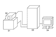
図1は、本発明に係る画像処理方法を実施するための画像処理システムについて説明するものである。画像処理システムは、距離画像カメラD1と、カラー画像カメラD2と、画像処理装置D3と、ディスプレイD4から構成されている。画像処理装置としては、例えば、特開2004−202007号公報の図1に記載されたものが存在する。画像処理装置は、画像処理プログラムによって3次元仮想空間を構成し、入力データに基づいて3次元仮想空間内にオブジェクトを定義し、仮想カメラから当該オブジェクトを見た映像を画面に表示する。 FIG. 1 illustrates an image processing system for carrying out an image processing method according to the present invention. The image processing system includes a distance image camera D1, a color image camera D2, an image processing device D3, and a display D4. As an image processing apparatus, for example, there is an apparatus described in FIG. 1 of JP-A-2004-202007. The image processing apparatus configures a three-dimensional virtual space by an image processing program, defines an object in the three-dimensional virtual space based on input data, and displays a video image of the object viewed from the virtual camera on the screen.
距離画像カメラ(D1)は、ある解像度(例えば、横128画素×縦123画素)を有し、その各画素について、被写体までの距離を、一定の時間間隔で連続的に、測定することができる。すなわち、距離画像カメラは画素毎に、撮影対象物の存在及び撮影対象物までの距離を赤外光の発光タイミングと反射光の受光タイミングとの時間差から求めることができ、画素毎に例えば8〜10ビットの分解能の値として算出する。距離画像カメラからの信号は信号線によって画像処理装置に出力されている。 The distance image camera (D1) has a certain resolution (for example, 128 horizontal pixels × 123 vertical pixels), and for each pixel, the distance to the subject can be continuously measured at regular time intervals. . That is, the distance image camera can determine the presence of the object to be photographed and the distance to the object to be photographed from the time difference between the light emission timing of the infrared light and the light reception timing of the reflected light for each pixel. Calculated as a 10-bit resolution value. A signal from the distance image camera is output to the image processing apparatus through a signal line.
カラー画像カメラ(D2)は、被写体をカラー画像の動画または静止画として撮影する装置であり、距離画像カメラに対してなるべく至近に、同一の方向を向けて設置される。ゲームの遊戯者は、これらのカメラの前で手や体を動かすと、画像処理装置は、距離画像カメラ(D1)及びカラー画像カメラ(D2)からのデータを入力とし、ゲームにおける衝突判定や画像処理等の各種処理を行い、結果をディスプレイ装置(D4)に映像として出力する。ディスプレイ装置(D4)は、画像処理装置からの出力映像を表示する装置である。尚、本画像処理システムにおいては、D1からD4までを携帯型情報処理装置のように1つの装置が全て備えていても良い。 The color image camera (D2) is a device that captures a subject as a moving image or a still image of a color image, and is installed in the same direction as close as possible to the distance image camera. When a game player moves his hand or body in front of these cameras, the image processing device receives data from the distance image camera (D1) and color image camera (D2) as input, and performs collision determination and image in the game. Various processing such as processing is performed, and the result is output as a video to the display device (D4). The display device (D4) is a device that displays an output video from the image processing device. In this image processing system, one device such as a portable information processing device may include all of D1 to D4.
図6は、本発明が適用される画像処理装置の一例であり、業務用または家庭用向けのゲーム装置およびパーソナルコンピュータや携帯型コンピュータ、携帯電話などに対応する。この装置は、プログラムにより動作し、装置全体を制御するCPUと、CPUが使用するプログラムやデータを格納するシステムメモリと、ゲームプログラムや出力する画像や音声などのデータが記憶されたプログラムデータ用ROMなどの記憶媒体と、装置を起動させた際に各ブロックを初期化するためのプログラムを格納するブートロムと、各ブロック間でプログラムやデータのやり取りを行うバスを制御するバスアービタと、ディスプレイに表示する(ポリゴン)オブジェクトの3次元仮想空間内での位置座標や向きを計算するジオメトリプロセッサと、ジオメトリプロセッサによって算出されたオブジェクトの向きや位置座標等に基づいて、ディスプレイに出力する画像を生成(描画)するレンダリングプロセッサと、それに接続され、画像を生成するためのデータやコマンドなど格納するグラフィックメモリと、スピーカに出力する音声を生成するオーディオプロセッサと、それに接続され、音声を生成するためのデータやコマンドなど格納するオーディオメモリとで構成される。 FIG. 6 is an example of an image processing apparatus to which the present invention is applied, and corresponds to a game device for business use or home use, a personal computer, a portable computer, a mobile phone, and the like. This device operates by a program and controls the entire device, a system memory that stores programs and data used by the CPU, and a program data ROM that stores game programs and data such as output images and sounds Such as a storage medium, a boot ROM that stores a program for initializing each block when the device is started, a bus arbiter that controls a bus for exchanging programs and data between the blocks, and a display on the display (Polygon) A geometry processor that calculates the position coordinates and orientation of an object in a three-dimensional virtual space, and generates (draws) an image to be output to the display based on the object orientation and position coordinates calculated by the geometry processor. Render processor and connected to it A graphic memory that stores data and commands for generating images, an audio processor that generates sound to be output to a speaker, and an audio memory that is connected to the memory and stores data and commands for generating sound Is done.
尚、システムメモリ、グラフィックメモリ、サウンドメモリは、1つのメモリをバスアービタに接続して各機能で共通に使用するようにしてもよく、各機能ブロックも機能として画像処理装置内に存在すればよく、機能ブロック同士が統合されていても、また、機能ブロック内部の各構成要素が他のブロックとして分離されていても良い。 The system memory, graphic memory, and sound memory may be used in common for each function by connecting one memory to the bus arbiter, and each functional block only needs to exist in the image processing apparatus as a function. The functional blocks may be integrated, or each component inside the functional block may be separated as another block.
プログラムデータ用のROMは、マスクロムやフラッシュロムなどの電気的にデータを読み出せるICメモリや、CD-ROM、DVD-ROMなどの光学的にデータを読み出せる装置と光ディスクまたは磁気ディスク等であっても良い。バスアービタには、外部からのデータ入出力を行うインターフェースが組み込まれており、ここに周辺装置としてのペリフェラルが接続される。 The ROM for program data is an IC memory that can read data electrically, such as mask chrome or flash ROM, a device that can read data optically such as CD-ROM, DVD-ROM, and an optical disk or magnetic disk. Also good. The bus arbiter incorporates an interface for inputting and outputting data from the outside, and a peripheral as a peripheral device is connected thereto.
ペリフェラルには、マウス(ポインティングデバイス)やキーボード、ゲーム用コントローラ等のキー操作のためのスイッチの他、プログラムの途中経過や生成したデータを保存するバックアップメモリ、表示装置、撮影装置等、画像処理装置本体あるいは他のペリフェラルに接続可能なものが含まれる。 Peripherals include mouse (pointing device), keyboard, switches for key operations such as game controllers, image processing devices such as backup memory, display device, photographing device, etc. Includes things that can be connected to the body or other peripherals.
(実施形態1)
次に、距離画像カメラから出力された情報を利用した画像処理の実施形態について説明する。ここで基本となる画像処理は、画面上方から仮想的なオブジェクトを複数落下させるものである。この画像処理は、画像処理装置が画像処理プログラムを実行することによって達成される。画像処理プログラムは、距離画像カメラから見た対象物(被写体)の座標系と仮想空間の座標系とを対応させて、距離画像カメラの出力から2次元又は3次元のモデルを生成し、これを仮想空間の座標系に配置する。
(Embodiment 1)
Next, an embodiment of image processing using information output from a distance image camera will be described. Here, the basic image processing is to drop a plurality of virtual objects from the top of the screen. This image processing is achieved by the image processing apparatus executing an image processing program. The image processing program generates a two-dimensional or three-dimensional model from the output of the distance image camera by associating the coordinate system of the object (subject) viewed from the distance image camera with the coordinate system of the virtual space. Place in the coordinate system of the virtual space.
このモデルは、画像として表示される物体であってもよいが、仮想空間に設けられた衝突判定領域に設定することもできる。画像処理プログラムは、距離画像カメラからある一定の距離(Tとする)より前方にある対象物(被写体)の部分を、仮想空間内において、対象物の2次元又は3次元のモデルと認識する。画像処理プログラムは、この部分を当り判定領域に設定し、オブジェクトが落下して当り判定領域に衝突した場合には、オブジェクトの軌道を変化させる。画像処理装置は、この様子を、カラー画像カメラからの被写体の実画像と合成して、ディスプレイ装置に表示する。 This model may be an object displayed as an image, but can also be set in a collision determination area provided in a virtual space. The image processing program recognizes the part of the object (subject) that is ahead of a certain distance (T) from the distance image camera as a two-dimensional or three-dimensional model of the object in the virtual space. The image processing program sets this portion as the hit determination area, and changes the trajectory of the object when the object falls and collides with the hit determination area. The image processing apparatus combines this state with the actual image of the subject from the color image camera and displays it on the display device.
図2は、距離画像カメラ得られたデータに基づいて、画像処理が作成した2次元のモデルである。右手を開いた人物が距離画像カメラに対して近づくと、前記Tより先にある、距離画像カメラの画素の距離データから、2次元のモデルを構成する。人物が距離画像カメラに近づくに従って、手(1)→上腕(2)→片手全体(3)→人物全体(4)が2次元モデルである、衝突判定領域として画像処理プログラムによって認定される。 FIG. 2 is a two-dimensional model created by image processing based on data obtained from a distance image camera. When a person whose right hand is opened approaches the distance image camera, a two-dimensional model is constructed from the distance data of the pixels of the distance image camera before T. As the person approaches the distance image camera, the hand (1) → the upper arm (2) → the entire one hand (3) → the entire person (4) is recognized by the image processing program as a collision determination region, which is a two-dimensional model.
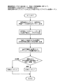
次に、この実施形態の動作のフローチャートを示す図3に基づいて説明する。先ず、画像処理装置は、距離画像カメラから、距離画像を取得する(ステップ300)。次いで、画像処理装置は、ステップ302において、距離画像を平滑化する(ノイズの除去)。距離画像カメラから取得した距離画像データには、実際の被写体までの距離とは無関係な、不正な値を含むことがある。この不正な値がノイズである。このノイズを除去する目的で、画像処理装置は、「空間方向の平滑化」と「時間方向の平滑化」をそれぞれ行う。
Next, a description will be given based on FIG. 3 showing a flowchart of the operation of this embodiment. First, the image processing apparatus acquires a distance image from the distance image camera (step 300). Next, in
空間方向の平滑化:距離画像の各画素に対し、近傍の4つの画素の値が比較され、これらの値のうち最大のものをもって、新たにこの画素の測定値とする。値の平均値ではなく最大値を取る理由は、ノイズの傾向として、実際より小さい値が得られる傾向があるためである。これにより、例えば画像内の1点のみに現れるようなノイズを除去することができる。 Smoothing in the spatial direction: For each pixel in the distance image, the values of the four neighboring pixels are compared, and the largest of these values is taken as the new measured value for this pixel. The reason for taking the maximum value instead of the average value is that there is a tendency to obtain a smaller value as the tendency of noise. Thereby, for example, noise that appears only at one point in the image can be removed.
時間方向の平滑化:画像処理装置は、今回の(空間方向に平滑化した結果の)距離画像データと、前回使用した距離画像データとを、各画素についてある割合で混ぜ合わせ、その結果をもって新たにその画素の測定値とする。これにより、例えば同一座標で値が一瞬だけ突然変化するようなタイプのノイズが測定値から除去される。 Smoothing in the time direction: The image processing apparatus mixes the current distance image data (result of smoothing in the spatial direction) and the previously used distance image data at a certain ratio for each pixel, and uses the result as a new result. The measured value of the pixel. Thereby, for example, the type of noise whose value suddenly changes for a moment at the same coordinate is removed from the measured value.
次いで、ステップ304において、画像処理装置は、距離画像の座標を、カラー画像の座標系に合わせて正規化する。距離画像カメラとカラー画像カメラとは、至近に設置し、同一の方向を向けてあるが、設置位置の違いや画角の違いなどにより、座標系に差が生じる。これを補正するため、距離画像に適切な拡大縮小及び平行移動を施すことで、カラー画像の座標系と一致させる。
Next, in
ステップ306では、画像処理装置は、ある距離の閾値Tを用いて、衝突領域ビットマップ(2次元画像)を作成する。これは距離画像のうちTより近い部分を抜き出す処理である。即ち、図4の(1)から(2)のビットマップ400が作成される。
In
先ず、画像処理装置は、距離画像カメラから、距離画像を取得する(ステップ300)。次いで、画像処理装置は、ステップ302において、距離画像を平滑化する(ノイズの除去)。距離画像カメラから取得した距離画像データには、実際の被写体までの距離とは無関係な、不正な値を含むことがある。この不正な値がノイズである。このノイズを除去する目的で、画像処理装置は、「空間方向の平滑化」と「時間方向の平滑化」をそれぞれ行う。
First, the image processing apparatus acquires a distance image from the distance image camera (step 300). Next, in
空間方向の平滑化:距離画像の各画素に対し、1近傍の4つの画素の値が比較され、これらの値のうち最大のものをもって、新たにこの画素の測定値とする。値の平均値ではなく最大値を取る理由は、ノイズの傾向として、実際より小さい値が得られる傾向があるためである。これにより、例えば画像内の1点のみに現れるようなノイズを除去することができる。 Smoothing in the spatial direction: For each pixel of the distance image, the values of four neighboring pixels are compared, and the largest of these values is taken as a new measured value for this pixel. The reason for taking the maximum value instead of the average value is that there is a tendency to obtain a smaller value as the tendency of noise. Thereby, for example, noise that appears only at one point in the image can be removed.
時間方向の平滑化:画像処理装置は、今回の(空間方向に平滑化した結果の)距離画像データと、前回使用した距離画像データとを、各画素についてある割合で混ぜ合わせ、その結果をもって新たにその画素の測定値とする。これにより、例えば同一座標で値が一瞬だけ突然変化するようなタイプのノイズが測定値から除去される。 Smoothing in the time direction: The image processing apparatus mixes the current distance image data (result of smoothing in the spatial direction) and the previously used distance image data at a certain ratio for each pixel, and uses the result as a new result. The measured value of the pixel. Thereby, for example, the type of noise whose value suddenly changes for a moment at the same coordinate is removed from the measured value.
次いで、ステップ304において、画像処理装置は、距離画像の座標を、カラー画像の座標系に合わせて正規化する。距離画像カメラとカラー画像カメラとは、至近に設置し、同一の方向を向けてあるが、設置位置の違いや画角の違いなどにより、座標系に差が生じる。これを補正するため、距離画像に適切な拡大縮小及び平行移動を施すことで、カラー画像の座標系と一致させる。
Next, in
ステップ306では、画像処理装置は、ある距離の閾値Tを用いて、衝突領域ビットマップ(2次元画像)を作成する。これは距離画像のうちTより近い部分を抜き出す処理である。即ち、図4の(1)から(2)のビットマップが作成される。
In
ステップ308では、画像処理装置は、オブジェクトの発生頻度の設定に基づき、画面上方に新しいオブジェクトを発生させる。例えば画面内に存在する「オブジェクト」の数がほぼ一定になるように調節したり、一時的に大量の「オブジェクト」を降らせたりすることができる。ステップ310では、画像処理装置は、各「オブジェクト」について、それぞれの運動ベクトルと、仮想的な重力に従って、1フレーム分動かす。
In
各「オブジェクト」は、それ自身の位置座標と運動ベクトルを持っている。画像処理装置は、運動ベクトルにフレームの時間差分を乗じたものを位置座標に足しこみ、これを新たな位置座標とする。仮想的な重力とは、「オブジェクト」に対し画面下方に働かせる力で、これにフレームの時間差分を乗じたものを運動ベクトルに足しこみ、これを新たな運動ベクトルとする。 Each “object” has its own position coordinates and motion vector. The image processing apparatus adds the motion vector multiplied by the time difference of the frame to the position coordinate, and sets this as a new position coordinate. Virtual gravity is a force that acts on the “object” in the lower part of the screen, and multiplies it by the time difference of the frame to add it to the motion vector, which is used as a new motion vector.
各「オブジェクト」について、画像処理装置は、図5の(1)から(2)にかけて示されているように、衝突領域ビットマップ500にオブジェクト502衝突したら、オブジェクトの運動ベクトルを変化させる。次いで、ステップ314に示すように、画像処理プログラムは、各「オブジェクト」について、画面外に出たら消去する。画像処理装置は、カラー画像カメラから、カラー画像を取得し(ステップ316)、カラー画像に「ぷよ」を合成した画像を作成し、ディスプレイ装置に出力する(ステップ318)。
For each “object”, the image processing apparatus changes the motion vector of the object when the
本実施例では、画像処理プログラムは、距離画像カメラから測定された被写体のデータから、2次元のモデル(衝突判定モデル)を作成したが、3次元モデルを作成するようにしても良い。この場合は、オブジェクトとの衝突判定も3次元的に実行可能である。 In this embodiment, the image processing program creates a two-dimensional model (collision determination model) from subject data measured by a distance image camera. However, a three-dimensional model may be created. In this case, the collision determination with the object can also be executed three-dimensionally.
(実施形態2)
落下物を楕円状のオブジェクトではなく、水流であり、画面全体で滝を表現する。落下する水流が衝突領域に衝突したら、水流の運動方向を変化させると同時に、その場所に水しぶきの映像効果を発生させる。水流が存在している場所では、合成するカラー画像を歪ませることで、水の屈折を表現する。衝突領域の下側などで水流が存在していない場所では、カラー画像を歪ませずに合成する。
(Embodiment 2)
The fallen object is not an elliptical object but a water stream, and the entire screen represents a waterfall. If the falling water current collides with the collision area, the moving direction of the water current is changed, and at the same time, the image effect of the splash is generated at that place. In the place where the water current exists, the refraction of water is expressed by distorting the color image to be synthesized. In places where there is no water flow, such as below the collision area, the color image is synthesized without distortion.
(実施形態3)
上記実施形態1および実施形態2では、距離の閾値Tを用いて、衝突領域ビットマップを作成していた。しかし、落下物の位置が奥行き方向に分布を持つ場合、固定の閾値を用いた判定はできない。その代わり、以下の方法で衝突判定を行う。距離画像の取得、平滑化、及び正規化は、図3の場合と同じである。この実施形態では、衝突領域ビットマップの作成は行わない。各落下物は、自身の位置に対応する、画像領域についての距離画像の値と、自身の奥行きの座標値とを比較し、距離画像の値のほうが自身の奥行きの座標値よりも小さい場合に、衝突したと判断する。なお、この実施形態の場合は、画像処理装置が被写体の3次元モデルを作成することにより、奥行き方向を持った落下物との衝突を判定することができる。
(Embodiment 3)
In the first embodiment and the second embodiment, the collision area bitmap is created using the distance threshold T. However, when the position of the falling object has a distribution in the depth direction, determination using a fixed threshold value cannot be performed. Instead, the collision is determined by the following method. The acquisition, smoothing, and normalization of the distance image is the same as in the case of FIG. In this embodiment, the collision area bitmap is not created. Each fallen object compares the distance image value for the image area corresponding to its own position with its depth coordinate value, and the distance image value is smaller than its own depth coordinate value. Judge that there was a collision. In the case of this embodiment, the image processing apparatus can determine a collision with a falling object having a depth direction by creating a three-dimensional model of a subject.
(実施形態4)
距離画像カメラからある一定の距離(Tとする)に、仮想的な水面(当り判断領域)を設定する。距離画像の各画素の値について、Tより小さな場合、水面に衝突があったと判定し、波を生成する。生成された波は、時間経過とともに、波動方程式に従って水面上を伝播し、波紋が形成され、水面上の各点には仮想的な勾配が生じる。この勾配に基づき、カラー画像を歪ませることで、水面に映る遊戯者の映像が波紋により揺らめく様を表現する。また、勾配の向きと程度により、合成画像の各画素の輝度を変化させることで、水と光の質感を表現する。
(Embodiment 4)
A virtual water surface (a hit determination area) is set at a certain distance (T) from the distance image camera. When the value of each pixel of the distance image is smaller than T, it is determined that there is a collision on the water surface, and a wave is generated. The generated wave propagates on the water surface according to the wave equation with time, and ripples are formed, and a virtual gradient is generated at each point on the water surface. By distorting the color image based on this gradient, the image of the player's image on the surface of the water is expressed by the ripples. Moreover, the texture of water and light is expressed by changing the luminance of each pixel of the composite image according to the direction and degree of the gradient.
(実施形態5)
画面内に、仮想的な小物体を複数設置する。距離画像カメラから取得した距離画像の各画素のうち、最も値が小さい(奥行きが浅い)所について、その距離の値Czと位置座標(Cx,Cy)とを検出する。Czがある設定値T1より近くなった場合、その座標に対して最も近くにある物体を「つかんだ」状態にする。「つかんだ」状態にある小物体は、時間経過に伴う(Cx,Cy)の変化に追従して、自身の位置座標を変化させる。これにより、例えば手で画面内の小物体を直接つかんで動かしているような操作感を得られる。ある小物体が「つかんだ」状態にあるときに、Czの値がある設定値T2より大きくなった場合、「つかんだ」状態は解除される。これにより、小物体をつかんだ手を引っ込めることで、その小物体をその場所に置くという操作感が得られる。
(Embodiment 5)
Multiple virtual small objects are installed in the screen. Among each pixel of the distance image acquired from the distance image camera, the distance value Cz and the position coordinates (Cx, Cy) are detected for the place where the value is the smallest (the depth is shallow). When Cz is closer than a certain set value T1, the object closest to the coordinates is put in a “grabbed” state. The small object in the “grabbed” state follows its change in (Cx, Cy) over time and changes its position coordinate. Thereby, it is possible to obtain an operational feeling that a small object in the screen is directly grabbed and moved by hand, for example. When a small object is in the “grabbed” state and the value of Cz becomes larger than a certain set value T2, the “gripped” state is canceled. Thereby, by retracting the hand holding the small object, an operation feeling of placing the small object at the place can be obtained.
(実施形態6)
画面内に、仮想的なボクシングの相手選手を作る。距離画像カメラから取得した距離画像の各画素のうち、最も値が小さい(奥行きが浅い)所について、その距離の値Czと位置座標(Cx,Cy)とを検出する。Czがある設定値T1より近くなった場合であって、かつ(Cx,Cy)が相手の顔や体の位置である場合、遊戯者は相手のその部位にパンチをあてたものと判定する。パンチを当てた部位により、相手の反応を変化させる。また、パンチがあたるまでの間、時間経過に伴う(Cx,Cy)の変化の履歴を記録していき、パンチが当たった際にその履歴を利用してパンチの種類を決定する。すなわち、(Cx,Cy)が右のほうから相手の顔の位置に向かって変化した場合、それは相手の顔への右フックであると判定する。
(Embodiment 6)
Make a virtual boxing opponent in the screen. Among each pixel of the distance image acquired from the distance image camera, the distance value Cz and the position coordinates (Cx, Cy) are detected for the place where the value is the smallest (the depth is shallow). If Cz is closer than a certain set value T1 and (Cx, Cy) is the position of the opponent's face or body, the player determines that the opponent has punched the part. The opponent's reaction is changed according to the punched area. Further, a history of changes in (Cx, Cy) with the passage of time is recorded until the punch hits, and when the punch hits, the type of punch is determined using the history. That is, if (Cx, Cy) changes from the right toward the position of the opponent's face, it is determined that it is a right hook to the opponent's face.
図7は、上記各実施例における距離画像カメラからの画素毎の出力データの例である。本発明の距離画像カメラは、赤外光を照射したタイミングと被写体に反射した赤外光を受光したタイミングとの時間差を位相差から算出する。これによって各画素における照射した赤外光の到達時間から距離が測定される。 FIG. 7 is an example of output data for each pixel from the range image camera in each of the above embodiments. The distance image camera of the present invention calculates the time difference between the timing of irradiating infrared light and the timing of receiving infrared light reflected on the subject from the phase difference. Thus, the distance is measured from the arrival time of the irradiated infrared light in each pixel.
測定された距離は、各画素8ビット乃至10ビットのデータで画像処理装置に読み出される。
各画素の距離データが8ビットの場合は0から255までの数値で被写体や背景までの距離が出力される。
The measured distance is read out to the image processing apparatus as data of 8 bits to 10 bits for each pixel.
When the distance data of each pixel is 8 bits, the distance to the subject or the background is output as a numerical value from 0 to 255.
図4の被写体を距離画像カメラにより撮影した場合、被写体の部分はカメラからの距離が背景よりも近いため、大きい数値(または小さい数値)で出力される。 When the subject in FIG. 4 is photographed by the distance image camera, the subject portion is output with a large numerical value (or a small numerical value) because the distance from the camera is closer than the background.
この場合は、背景に当たる部分は、被写体(人物)よりカメラから遠いので、小さい数値が出力され、被写体の部分は、背景よりカメラに近いので大きい数値が出力される。
尚、距離によって数値を大きくするか小さくするかは距離を算出する計算式の設定により変更可能である。そして、これら距離を示す数値に対して閾値を設定して、閾値より数値が大きいか小さいかで被写体を抽出する。
In this case, since the portion corresponding to the background is farther from the camera than the subject (person), a small numerical value is output, and since the portion of the subject is closer to the camera than the background, a large numerical value is output.
Whether the numerical value is increased or decreased depending on the distance can be changed by setting a calculation formula for calculating the distance. Then, a threshold is set for the numerical values indicating these distances, and the subject is extracted depending on whether the numerical value is larger or smaller than the threshold.
本発明においては、例えば家庭内でビデオゲームに用いることを想定すると、およそ1.5〜3mくらいの距離が想定されるため、この範囲に被写体が進入したときの被写体までの距離のみが抽出できるような数値として100の値を閾値に設定している。このようにすることで、被写体のみの距離情報を抽出することが出来る。 In the present invention, assuming that it is used for a video game at home, for example, a distance of about 1.5 to 3 m is assumed. Therefore, only the distance to the subject when the subject enters this range can be extracted. As such a numerical value, a value of 100 is set as the threshold value. In this way, distance information of only the subject can be extracted.
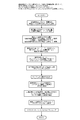
図8および図9は、抽出した被写体の距離情報に基づいて、当たり判定の領域を設定するプログラムのフローである。図8のプログラムフローは、図3での説明とほぼ同様であるが、図9は、3次元の当たり判定領域を生成するフローとなっている。 FIG. 8 and FIG. 9 are flowcharts of a program for setting a hit determination area based on the extracted subject distance information. The program flow in FIG. 8 is almost the same as the description in FIG. 3, but FIG. 9 is a flow for generating a three-dimensional hit determination area.
3次元である奥行き方向の当たり判定には、距離画像カメラから読み出した被写体に対応する各画素の2次元座標を仮想空間の2次元座標に対応付けて変換するステップに加えて、各画素の距離データを仮想空間の奥行き方向の座標に変換することで、立体形状の当たり判定領域を設定している。 In the three-dimensional depth direction hit determination, in addition to the step of converting the two-dimensional coordinates of each pixel corresponding to the subject read from the distance image camera in association with the two-dimensional coordinates of the virtual space, the distance of each pixel A three-dimensional shape hit determination region is set by converting data into coordinates in the depth direction of the virtual space.
図10は、図9の立体形状の当たり判定を設定する技術を応用した、表示モデルを生成するプログラムステップである。 FIG. 10 is a program step for generating a display model to which the technique for setting the hit determination of the solid shape in FIG. 9 is applied.
このプログラムでは、被写体に対応する各画素を3次元座標に変換後、その隣り合う座標を組にして複数の多角形を生成する。更に、多角形を対角線で分割し、ポリゴンの1単位となる三角形の3頂点を組にしたポリゴンモデルを生成する。 In this program, after converting each pixel corresponding to the subject into three-dimensional coordinates, a plurality of polygons are generated by combining the adjacent coordinates. Further, the polygon is divided by a diagonal line, and a polygon model is generated by combining three vertices of a triangle that is one unit of the polygon.
ポリゴンモデルの生成方法については、上記の他に、3次元座標に変換した各画素を所定の順番で3つずつ組にしてポリゴンを1つずつ生成していく方法でも何れでも良い。
ポリゴンモデルの生成後は、そのままレンダリング処理を行っても良いが、CCDカメラD2により撮影された画像をテクスチャに用いて、ポリゴンモデルにマッピング処理しても良い。
As a method for generating a polygon model, in addition to the above, any method may be used in which each pixel converted into three-dimensional coordinates is grouped three by three in a predetermined order to generate a polygon one by one.
After the generation of the polygon model, the rendering process may be performed as it is, or the image captured by the CCD camera D2 may be used as a texture and mapped to the polygon model.
距離画像センサからの画素のうち、抽出された画素に対応するCCDによる撮影画素の抽出を行い、この抽出した画素をテクスチャデータとしてグラフィックメモリに記憶させる。このようにコンピュータに処理させることで、距離画像カメラからの距離情報に基づいて生成された立体オブジェクトにテクスチャマッピングを行なうことが可能になる。 Of the pixels from the distance image sensor, a photographic pixel is extracted by the CCD corresponding to the extracted pixel, and the extracted pixel is stored in the graphic memory as texture data. By making the computer process in this way, it is possible to perform texture mapping on the three-dimensional object generated based on the distance information from the distance image camera.
Claims (7)
前記画像処理装置は、前記距離画像カメラからの出力に基づいて、画像処理プログラムにより定義される仮想空間内に2次元又は3次元のモデルを生成し、このモデルと仮想空間内の当り判定領域との当り判定を行い、この判定結果に応じて前記画像処理を実行する画像処理方法。 In an image processing method that includes a distance image camera and an image processing device, inputs an output of the distance image camera to the image processing device, and executes predetermined image processing.
The image processing device generates a two-dimensional or three-dimensional model in a virtual space defined by an image processing program based on an output from the distance image camera, and the model and a hit determination region in the virtual space An image processing method for performing a hit determination and executing the image processing according to the determination result.
前記画像処理装置は、前記距離画像カメラからの出力に基づいて、画像処理プログラムにより定義される仮想空間内に2次元又は3次元のモデルを生成し、このモデルと仮想空間内のオブジェクトとの当り判定を行い、この判定結果に応じて前記画像処理を実行する画像処理方法。 In an image processing method comprising a range image camera and an image processing device, the output of the range image camera is input to the image processing device, and predetermined image processing is executed.
The image processing device generates a two-dimensional or three-dimensional model in a virtual space defined by an image processing program based on an output from the distance image camera, and hits the model with an object in the virtual space. An image processing method for performing determination and executing the image processing according to the determination result.
前記画像処理装置は、前記距離画像カメラからの出力に基づいて、画像処理プログラムにより定義される仮想空間内に2次元又は3次元のモデルを前記仮想空間内に生成する画像処理方法。 In an image processing method that includes a distance image camera and an image processing device, inputs an output of the distance image camera to the image processing device, and executes predetermined image processing.
The image processing apparatus generates an two-dimensional or three-dimensional model in the virtual space in a virtual space defined by an image processing program based on an output from the distance image camera.
A storage medium such as a DVD, a CD, and a hard disk in which the program according to claim 6 is stored.
Priority Applications (1)
| Application Number | Priority Date | Filing Date | Title |
|---|---|---|---|
| JP2005181356A JP2007004318A (en) | 2005-06-22 | 2005-06-22 | Image processing method, program for executing image processing and storage medium with its program stored |
Applications Claiming Priority (1)
| Application Number | Priority Date | Filing Date | Title |
|---|---|---|---|
| JP2005181356A JP2007004318A (en) | 2005-06-22 | 2005-06-22 | Image processing method, program for executing image processing and storage medium with its program stored |
Publications (2)
| Publication Number | Publication Date |
|---|---|
| JP2007004318A true JP2007004318A (en) | 2007-01-11 |
| JP2007004318A5 JP2007004318A5 (en) | 2008-08-07 |
Family
ID=37689907
Family Applications (1)
| Application Number | Title | Priority Date | Filing Date |
|---|---|---|---|
| JP2005181356A Withdrawn JP2007004318A (en) | 2005-06-22 | 2005-06-22 | Image processing method, program for executing image processing and storage medium with its program stored |
Country Status (1)
| Country | Link |
|---|---|
| JP (1) | JP2007004318A (en) |
Cited By (9)
| Publication number | Priority date | Publication date | Assignee | Title |
|---|---|---|---|---|
| JP2010516153A (en) * | 2007-01-14 | 2010-05-13 | マイクロソフト インターナショナル ホールディングス ビイ.ヴイ. | Method, apparatus and system for image processing |
| JP2011215920A (en) * | 2010-03-31 | 2011-10-27 | Namco Bandai Games Inc | Program, information storage medium and image generation system |
| JP2012527025A (en) * | 2009-05-14 | 2012-11-01 | アルカテル−ルーセント | Method for generating a three-dimensional model of an object |
| JP2013097806A (en) * | 2011-11-01 | 2013-05-20 | Samsung Electronics Co Ltd | Video processor and video processing method |
| JP2015019346A (en) * | 2013-06-12 | 2015-01-29 | 日本放送協会 | Parallax image generator |
| KR101526866B1 (en) * | 2009-01-21 | 2015-06-10 | 삼성전자주식회사 | Method of filtering depth noise using depth information and apparatus for enabling the method |
| CN105051792A (en) * | 2012-12-26 | 2015-11-11 | 英特尔公司 | Apparatus for enhancement of 3-D images using depth mapping and light source synthesis |
| JP2018055257A (en) * | 2016-09-27 | 2018-04-05 | キヤノン株式会社 | Information processing device, control method thereof, and program |
| CN111921199A (en) * | 2020-08-25 | 2020-11-13 | 腾讯科技(深圳)有限公司 | Virtual object state detection method, device, terminal and storage medium |
Citations (8)
| Publication number | Priority date | Publication date | Assignee | Title |
|---|---|---|---|---|
| JPH1153563A (en) * | 1997-07-31 | 1999-02-26 | Sony Corp | Device and method for attitude detection game |
| JPH1188910A (en) * | 1997-09-02 | 1999-03-30 | Canon Inc | Three-dimension model generating device, three-dimension model generating method, medium recording three-dimension model generating program three-dimension model reproduction device, three-dimension model reproduction method and medium recording three-dimension model reproduction program |
| JP2000020193A (en) * | 1998-06-29 | 2000-01-21 | Toshiba Corp | Method and unit for virtual body control and record medium |
| JP2000172878A (en) * | 1998-12-09 | 2000-06-23 | Sony Corp | Device and method for processing information and distribution medium |
| JP2003057007A (en) * | 2001-08-10 | 2003-02-26 | Matsushita Electric Works Ltd | Human body detection method using distance image |
| JP2003296707A (en) * | 2002-03-29 | 2003-10-17 | Toshiba Corp | Device and method for generating three-dimensional object |
| JP2004202007A (en) * | 2002-12-26 | 2004-07-22 | Sega Corp | Electronic game device, method of processing image for electronic game, program for performing it, and storage medium with the program stored |
| JP2004283419A (en) * | 2003-03-24 | 2004-10-14 | Namco Ltd | Game information, information storage medium and game device |
-
2005
- 2005-06-22 JP JP2005181356A patent/JP2007004318A/en not_active Withdrawn
Patent Citations (8)
| Publication number | Priority date | Publication date | Assignee | Title |
|---|---|---|---|---|
| JPH1153563A (en) * | 1997-07-31 | 1999-02-26 | Sony Corp | Device and method for attitude detection game |
| JPH1188910A (en) * | 1997-09-02 | 1999-03-30 | Canon Inc | Three-dimension model generating device, three-dimension model generating method, medium recording three-dimension model generating program three-dimension model reproduction device, three-dimension model reproduction method and medium recording three-dimension model reproduction program |
| JP2000020193A (en) * | 1998-06-29 | 2000-01-21 | Toshiba Corp | Method and unit for virtual body control and record medium |
| JP2000172878A (en) * | 1998-12-09 | 2000-06-23 | Sony Corp | Device and method for processing information and distribution medium |
| JP2003057007A (en) * | 2001-08-10 | 2003-02-26 | Matsushita Electric Works Ltd | Human body detection method using distance image |
| JP2003296707A (en) * | 2002-03-29 | 2003-10-17 | Toshiba Corp | Device and method for generating three-dimensional object |
| JP2004202007A (en) * | 2002-12-26 | 2004-07-22 | Sega Corp | Electronic game device, method of processing image for electronic game, program for performing it, and storage medium with the program stored |
| JP2004283419A (en) * | 2003-03-24 | 2004-10-14 | Namco Ltd | Game information, information storage medium and game device |
Cited By (12)
| Publication number | Priority date | Publication date | Assignee | Title |
|---|---|---|---|---|
| JP2010516153A (en) * | 2007-01-14 | 2010-05-13 | マイクロソフト インターナショナル ホールディングス ビイ.ヴイ. | Method, apparatus and system for image processing |
| KR101526866B1 (en) * | 2009-01-21 | 2015-06-10 | 삼성전자주식회사 | Method of filtering depth noise using depth information and apparatus for enabling the method |
| JP2012527025A (en) * | 2009-05-14 | 2012-11-01 | アルカテル−ルーセント | Method for generating a three-dimensional model of an object |
| JP2011215920A (en) * | 2010-03-31 | 2011-10-27 | Namco Bandai Games Inc | Program, information storage medium and image generation system |
| JP2013097806A (en) * | 2011-11-01 | 2013-05-20 | Samsung Electronics Co Ltd | Video processor and video processing method |
| CN105051792A (en) * | 2012-12-26 | 2015-11-11 | 英特尔公司 | Apparatus for enhancement of 3-D images using depth mapping and light source synthesis |
| JP2016505968A (en) * | 2012-12-26 | 2016-02-25 | インテル・コーポレーション | Apparatus for 3D image enhancement using depth mapping and light source synthesis |
| US9536345B2 (en) | 2012-12-26 | 2017-01-03 | Intel Corporation | Apparatus for enhancement of 3-D images using depth mapping and light source synthesis |
| JP2015019346A (en) * | 2013-06-12 | 2015-01-29 | 日本放送協会 | Parallax image generator |
| JP2018055257A (en) * | 2016-09-27 | 2018-04-05 | キヤノン株式会社 | Information processing device, control method thereof, and program |
| CN111921199A (en) * | 2020-08-25 | 2020-11-13 | 腾讯科技(深圳)有限公司 | Virtual object state detection method, device, terminal and storage medium |
| CN111921199B (en) * | 2020-08-25 | 2023-09-26 | 腾讯科技(深圳)有限公司 | Method, device, terminal and storage medium for detecting state of virtual object |
Similar Documents
| Publication | Publication Date | Title |
|---|---|---|
| JP2007004318A (en) | Image processing method, program for executing image processing and storage medium with its program stored | |
| US10293252B2 (en) | Image processing device, system and method based on position detection | |
| JP6548518B2 (en) | INFORMATION PROCESSING APPARATUS AND INFORMATION PROCESSING METHOD | |
| US9344707B2 (en) | Probabilistic and constraint based articulated model fitting | |
| JP5773944B2 (en) | Information processing apparatus and information processing method | |
| EP2724318B1 (en) | Fully automatic dynamic articulated model calibration | |
| JP4473754B2 (en) | Virtual fitting device | |
| JP6587435B2 (en) | Image processing apparatus, information processing method, and program | |
| WO2015122079A1 (en) | Information processing device and information processing method | |
| JP5251987B2 (en) | Person determination device, method and program | |
| JP6189170B2 (en) | Posture estimation device | |
| KR20140019765A (en) | Depth camera based on structured light and stereo vision | |
| JP6873344B2 (en) | Fatigue judgment device, fatigue judgment method, and fatigue judgment program | |
| JP3732757B2 (en) | Image recognition method and image recognition apparatus | |
| CN111801725A (en) | Image display control device and image display control program | |
| JP6300560B2 (en) | Information processing apparatus and information processing method | |
| JP2010152557A (en) | Image processor and image processing method | |
| JP5307060B2 (en) | Image processing apparatus, image processing method, and program | |
| JP4218963B2 (en) | Information extraction method, information extraction apparatus, and recording medium | |
| JP2016525235A (en) | Method and device for character input | |
| Xu et al. | Bare hand gesture recognition with a single color camera | |
| TW201928761A (en) | Apparatus and method of image capture | |
| KR101909326B1 (en) | User interface control method and system using triangular mesh model according to the change in facial motion | |
| KR101050107B1 (en) | Video controller | |
| JP7024876B2 (en) | Detection device, processing device, detection method, and processing program |
Legal Events
| Date | Code | Title | Description |
|---|---|---|---|
| A521 | Request for written amendment filed |
Free format text: JAPANESE INTERMEDIATE CODE: A523 Effective date: 20080623 |
|
| A621 | Written request for application examination |
Free format text: JAPANESE INTERMEDIATE CODE: A621 Effective date: 20080623 |
|
| A977 | Report on retrieval |
Free format text: JAPANESE INTERMEDIATE CODE: A971007 Effective date: 20100924 |
|
| A131 | Notification of reasons for refusal |
Free format text: JAPANESE INTERMEDIATE CODE: A131 Effective date: 20101005 |
|
| RD04 | Notification of resignation of power of attorney |
Free format text: JAPANESE INTERMEDIATE CODE: A7424 Effective date: 20101019 |
|
| A761 | Written withdrawal of application |
Free format text: JAPANESE INTERMEDIATE CODE: A761 Effective date: 20101111 |