JP2007003992A - Image forming apparatus - Google Patents
Image forming apparatus Download PDFInfo
- Publication number
- JP2007003992A JP2007003992A JP2005186250A JP2005186250A JP2007003992A JP 2007003992 A JP2007003992 A JP 2007003992A JP 2005186250 A JP2005186250 A JP 2005186250A JP 2005186250 A JP2005186250 A JP 2005186250A JP 2007003992 A JP2007003992 A JP 2007003992A
- Authority
- JP
- Japan
- Prior art keywords
- medium
- idling
- time
- printing
- image forming
- Prior art date
- Legal status (The legal status is an assumption and is not a legal conclusion. Google has not performed a legal analysis and makes no representation as to the accuracy of the status listed.)
- Pending
Links
Images


Landscapes
- Fixing For Electrophotography (AREA)
- Control Or Security For Electrophotography (AREA)
Abstract
Description
本発明は、画像形成装置に関し、特に印刷直後に於ける定着器の空回転機能を有する画像形成装置に関するものである。 The present invention relates to an image forming apparatus, and more particularly to an image forming apparatus having an idling function of a fixing device immediately after printing.
プリンタ等の画像形成装置では、定着器の温度変動幅を小さくする技術の開発が進められている(特許文献1参照)。この技術では、動作開始直後には、加熱ローラの表面温度を上昇させるために、加熱ローラ内部に備えるヒータにフル通電し、熱定着通紙中には、加熱ローラの表面温度を一定温度に維持するために通電をオン・オフ制御している。又、動作終了時には、通紙の残り枚数が所定量になると、ヒータへの通電をオフすることとしている。更に、通電終了後も加熱ローラを空回転させている。この空回転とは、通紙終了後に加熱ローラの表面温度が不必要に上昇するのを防止するために複数回空転させる処置である。 In an image forming apparatus such as a printer, a technique for reducing a temperature fluctuation range of a fixing device is being developed (see Patent Document 1). In this technology, immediately after the start of operation, in order to raise the surface temperature of the heating roller, the heater provided in the heating roller is fully energized, and the surface temperature of the heating roller is maintained at a constant temperature during the heat fixing paper passing. In order to do this, energization is controlled on and off. At the end of the operation, when the remaining number of sheets to be passed reaches a predetermined amount, the power supply to the heater is turned off. Furthermore, the heating roller is idled after energization. This idling is a process of idling a plurality of times in order to prevent the surface temperature of the heating roller from unnecessarily rising after the end of paper passing.
上記技術では、通紙終了後に、その時の加熱ローラの表面温度に係らず、必ず空回転させることとしている。従って、加熱ローラの表面温度が、目標とする温度よりも低いときには、空回転させることによってより一層表面温度が低下してしまう。その結果、後に続く印刷ジョブの印刷起動時には、所定の表面温度まで上昇させることが必要になってくる。即ち、この空回転によって後に続く印刷ジョブの印刷起動時に於けるパフォーマンスを低下させていた。
解決しようとする問題点は、従来の技術では、加熱ローラの表面温度が、目標とする温度よりも低いときであっても、空回転させていたため、空回転させることによって表面温度がより一層低下してしまい、後に続く印刷ジョブの印刷起動時には、所定の表面温度まで上昇させることが必要になってくるため、後に続く印刷ジョブの印刷起動時におけるパフォーマンスを低下させていた点である。 The problem to be solved is that, in the conventional technology, even when the surface temperature of the heating roller is lower than the target temperature, the surface temperature is further decreased by idle rotation. As a result, it is necessary to increase the surface temperature to a predetermined surface temperature when printing of a subsequent print job is started, so that the performance at the time of starting printing of a subsequent print job is lowered.
本発明による画像形成装置は、媒体搬送路上に配設され印刷媒体の定着処理を実行する加熱部材と、該加熱部材への通電を制御する温度制御部と、上記加熱部材の回転を制御する回転駆動制御部と、上記媒体搬送路上を搬送される上記印刷媒体を検出する媒体検出手段とを有し、上記印刷媒体が上記加熱部材を通過後に上記通電を停止したまま上記加熱部材を所定時間空回転可能な画像形成装置であって、上記媒体検出手段を監視し、印刷ジョブに於ける最終ページの印刷終了を検出すると、上記印刷ジョブに含まれていたページ数を検出する連続印刷数検出手段と、該連続印刷数検出手段から上記印刷ジョブに含まれていたページ数を受入れて上記加熱部材の空回転時間を設定する空回転時間設定手段とを備えることを主要な特徴とする。 An image forming apparatus according to the present invention includes a heating member that is disposed on a medium conveyance path and performs a fixing process of a print medium, a temperature control unit that controls energization of the heating member, and a rotation that controls rotation of the heating member. A drive control unit; and a medium detection unit configured to detect the print medium conveyed on the medium conveyance path, and the heating member is emptied for a predetermined time while the energization is stopped after the print medium passes through the heating member. A rotatable image forming apparatus that monitors the medium detecting means and detects the number of pages included in the print job when the end of printing of the last page in the print job is detected. And an idling time setting means for accepting the number of pages included in the print job from the continuous printing number detecting means and setting the idling time of the heating member.
連続印刷数検出手段と、空回転時間設定手段とを備えることによって、印刷直後に於ける加熱ローラの表面温度を考慮し、該表面温度に基づいて適切な空回転時間を設定することが出来るようになる。その結果、後に続く印刷ジョブの印刷起動時におけるパフォーマンスを向上させることが出来るという効果を得る。 By providing the continuous printing number detecting means and the idling time setting means, it is possible to set an appropriate idling time based on the surface temperature in consideration of the surface temperature of the heating roller immediately after printing. become. As a result, it is possible to improve the performance at the time of starting printing of the subsequent print job.
本発明では、上記、連続印刷数検出手段、及び空回転時間設定手段を、従来の画像形成装置に於ける制御プログラムの変更のみによって実現した。 In the present invention, the continuous printing number detecting means and the idling time setting means are realized only by changing the control program in the conventional image forming apparatus.
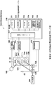
図1は、本発明による画像形成装置の概略構成説明図である。
図において、1は画像形成装置本体を示している。2は印刷媒体である。3は媒体カセットであり、印刷前の印刷媒体2を収納するカセットである。40は媒体カセット3から印刷媒体2を一枚毎に分離して矢印60の方向へ引き出すピックアップローラである。41、42はレジストローラであり、互いに圧接して配設され一対となって印刷媒体2を挟持して矢印61の方向へ移動させるローラである。43、44もレジストローラであり、互いに圧接して配設され一対となって印刷媒体2を挟持して搬送ベルトユニット20へ供給するローラである。
FIG. 1 is an explanatory diagram of a schematic configuration of an image forming apparatus according to the present invention.
In the figure,
11、12、13、14は全て電子写真プロセスユニットであり、受入れた印刷データに基づいてそれぞれ記載順に、シアン、マゼンタ、イエロー、ブラックのトナー像を生成する部分である。20は、搬送ベルトユニットであり、静電気力によって密着する印刷媒体2を矢印62の方向に搬送する部分である。搬送ベルトユニット20には転写ローラ、21、22、23、24が内蔵されている。この転写ローラ、21、22、23、24に高電圧が印加され、電子写真プロセスユニットで生成されたトナー像は、印刷媒体2上に転写される。
30は定着器であり、印刷媒体2上に転写されたトナー像を加熱定着する部分である。定着器30は、加圧ローラ100と、加熱ローラ102とを内蔵している。この加圧ローラ100と、加熱ローラ102とは、互いに圧接して配設され、トナー像が転写された印刷媒体2を加圧・加熱している。又、加圧ローラ100は加圧ヒータ101を、加熱ローラ102は加熱ヒータ103を、それぞれ内蔵している。31はサ−ミスタであり、定着器30に内蔵され、加熱ローラ102の表面温度を計測する温度センサである。
47、48は排出ローラであり、互いに圧接して配設され、一対となって定着後の印刷媒体2を65の方向へ移動させている。50、51、52は媒体検出センサであり、印刷媒体2が通過する度毎に、その先端部と後端部とを検出するメカセンサである。4は排出カセットであり、印刷後に排出された印刷媒体2を収納するカセットである。空回転時間制御系統130は、定着器30を空回転制御する部分である。この空回転時間制御系統130の詳細について説明する。
図2は、実施例1の空回転時間制御系統ブロック図である。
図に示すように、空回転時間制御系統130は、制御部110と、モータ駆動制御部120と、温度検出部121と、温度制御部122とを備える。
FIG. 2 is a block diagram of the idling time control system of the first embodiment.
As shown in the figure, the idling
制御部110は、CPU111と、ROM112と、RAM113と、タイマ114と、連続印刷数検出手段115と、空回転時間設定手段116と、外部インタフェース117とを有し、媒体搬送を所定間隔以下で連続して印刷した枚数を検出し、この印刷枚数に応じて、加圧ローラ100、及び加熱ローラ102の空回転時間を設定し、両ローラの温度を適切に制御することによって後に続く印刷ジョブの印刷起動時におけるパフォーマンスを向上させる部分である。
The
CPU111は、ROM112に予め格納されている制御プログラムを実行することによって画像形成装置1(図1)全体を制御するマイクロプロセッサである。特に、本実施例では、ROM112に予め格納されている、所定の制御データを用い、所定の制御プログラムを実行することによって、後述する連続印刷数検出手段115と空回転時間設定手段116とを起動させる部分である。
The
ROM112は、CPU111が実行することによって画像形成装置1(図1)全体を制御する制御プログラム及びそれに必要な制御データを予め格納するリードオンリーメモリである。本実施例では、特にCPU111が実行することによって後述する連続印刷数検出手段115と空回転時間設定手段116とを起動させる制御プログラム、及び空回転時間テーブル112−1(後に詳細に説明する)とを格納するリードオンリーメモリである。
The
RAM113は、CPU111が所定の制御プログラムを実行する中で必要になる演算領域を提供するランダムアクセスメモリである。更に、CPU111が外部インタフェース117を介して他の部分とのデータのやり取りを実行するときに必要なデータ保持領域を提供するランダムアクセスメモリでもある。
タイマ114は、CPU111が実行する制御の中で必要になる経過時間計測手段である。
The
The
連続印刷数検出手段115は、連続印刷時に定着器30を通過する印刷媒体の媒体間隙を検出し、所定の間隔以下の媒体間隔で連続して印刷されたページ数を検出する部分である。この部分は、CPU111が、ROM112に予め格納されている所定の制御プログラムを実行することによって起動されるコンピュータ制御手段である。
尚、本実施例では、一例として印刷媒体が16mmから65mmの媒体間隙で搬送される場合を連続印刷としている。
The continuous printing number detecting means 115 is a part that detects the medium gap of the printing medium passing through the
In this embodiment, as an example, continuous printing is performed when the print medium is conveyed with a medium gap of 16 mm to 65 mm.
ここで16mmとは、媒体検出センサ52の機械的レバーが媒体有りから媒体無しに戻るまでの時間0.1秒に対して、搬送速度を掛けた値である。通常カラー印刷における媒体搬送速度は163mm/sであり16.3mmとなるので16mmとしている。一方、65mmは、通常カラー印字速度37ppm(ppmは、1分間あたりに印刷する枚数を示した単位であり、本実施例の場合は、A4サイズまたはレターサイズの用紙を横送りに印刷する印刷速度である)を実現するため、50mm以下の媒体搬送間隔が必要であるが、画処理の遅れや間隔検出の際の媒体端の検出ばらつきを勘案し、一例として65mmとしている。この媒体搬送間隔を監視することによって、その間隔で連続印刷されたページ数を検出することが出来る。
Here, 16 mm is a value obtained by multiplying the time required for the mechanical lever of the
次に、媒体搬送間隔の監視方法の一例について説明する。
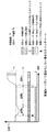
図3は、媒体搬送間隔の監視方法説明図である。
図は、縦軸に媒体検出センサ52(図2)の出力電圧レベルを示し、横軸に時間経過を表している。但し、媒体検出センサ52(図2)の出力電圧は、媒体無しレベルが1であり、媒体有りレベルが0であるものとする。
Next, an example of a method for monitoring the medium conveyance interval will be described.
FIG. 3 is an explanatory diagram of a method for monitoring the medium conveyance interval.
In the figure, the vertical axis represents the output voltage level of the medium detection sensor 52 (FIG. 2), and the horizontal axis represents time. However, the output voltage of the medium detection sensor 52 (FIG. 2) is assumed to be 1 when the medium is not present and 0 when the medium is present.
図に示すように、連続印刷数検出手段115(図2)は、外部インタフェースを介し媒体検出センサ52(図2)の出力電圧を受入れて、媒体搬送間隔、即ち、媒体後端から媒体先端までの時間t1を計測し、媒体搬送間隔L(mm)=t1(s)×Vc(mm/s)として求めることが出来る。この媒体搬送間隔L(mm)が上記65mm以上になったときに連続印刷数検出手段115は、連続印刷時の最終を検出することが出来る。更に、当該連続印刷の印刷開始時点からの媒体有レベルの回数をカウントしておき、最終ページを検出時点でのカウント値から連続印刷されたページ数を検出することが出来る。
As shown in the figure, the continuous printing number detection means 115 (FIG. 2) receives the output voltage of the medium detection sensor 52 (FIG. 2) via the external interface, and the medium conveyance interval, that is, from the medium rear end to the medium front end. The time t1 is measured, and it can be obtained as medium conveyance interval L (mm) = t1 (s) × Vc (mm / s). When the medium conveyance interval L (mm) is equal to or greater than 65 mm, the continuous printing
図2に戻って、空回転時間設定手段116は、連続印刷数検出手段115から受入れた連続印刷されたページ数に基づいて、最終ページの印刷終了後における加熱ローラ102の空回転時間を設定する部分である。ここで、最初に加熱ローラ102の空回転による効果について説明する。
Returning to FIG. 2, the idling
図4は、実施例1に於いて空回転しない場合のタイムチャートである。
連続印刷の場合、最初の印刷媒体の先端部が、目標温度Ttに調節された加熱ローラ102(図2)と加圧ローラ100が圧接されたニップ部104(図2)を通過する際、定着に必要な熱量を加熱ローラ102(図2)と加圧ローラ100から奪うために、加熱ローラ102(図2)の表面温度が低下する(区間a)。このとき温度制御部122(図2)は、加熱ローラ102(図2)の表面温度を目標温度Ttに近づけようとして、加熱ヒータ103(図2)、及び必要に応じて加圧ヒータ101(図2)を制御する。この制御はAC電源126と、加熱ヒータ103(図2)との間に配設されるスイッチ125、及びAC電源126と加圧ヒータ101(図2)との間に配設されるスイッチ124、とをオン・オフすることによって実行される。
FIG. 4 is a time chart in the case of no idling in the first embodiment.
In the case of continuous printing, when the leading end of the first print medium passes through the heating roller 102 (FIG. 2) adjusted to the target temperature Tt and the nip portion 104 (FIG. 2) where the
加熱ローラ102(図2)の表面温度が目標温度Ttに近づいた後、一定の温度に制御される(区間b)。この区間bでは、加熱ローラ102(図2)による印刷媒体への投入熱量と、印刷媒体が搬送されながら吸収する熱量とのバランスが確保される。区間bの最後では、連続印刷の最後の印刷媒体の後端部がニップ部104(図2)を通過し、媒体検出センサ52(図2)を通過したことを連続印刷数検出手段115(図2)が検出すると、加熱ローラ102(図2)、及び加圧ローラ100(図2)を回転駆動しているモータ105が、モータ駆動制御部120によって停止される。
After the surface temperature of the heating roller 102 (FIG. 2) approaches the target temperature Tt, it is controlled to a constant temperature (section b). In this section b, a balance is ensured between the amount of heat input to the print medium by the heating roller 102 (FIG. 2) and the amount of heat absorbed while the print medium is conveyed. At the end of the section b, the continuous printing number detecting means 115 (FIG. 2) indicates that the trailing edge of the last printing medium in the continuous printing has passed the nip portion 104 (FIG. 2) and the medium detection sensor 52 (FIG. 2). When 2) is detected, the
更に、加熱ヒータ103(図2)、及び加圧ヒータ101(図2)は、温度制御部122(図2)によって強制的にオフされる。そのタイミングを図中△のタイミングとする。そのタイミング△よりも若干遅れて加熱ローラ102(図2)、及び加圧ローラ100(図2)が回転停止する。この時点から区間cが開始する。この区間cでは、加熱ローラ102(図2)が投入していた熱量の放出先が無くなり、加熱ローラ102(図2)の表面温度が急激に所定値まで上昇する。この状態を以下にオーバーシュートと記す。このときのオーバーシュートをY1とする。 Furthermore, the heater 103 (FIG. 2) and the pressure heater 101 (FIG. 2) are forcibly turned off by the temperature controller 122 (FIG. 2). The timing is assumed to be a time Δ in the figure. The heating roller 102 (FIG. 2) and the pressure roller 100 (FIG. 2) stop rotating slightly after the timing Δ. From this point, section c starts. In this section c, the heat amount released by the heating roller 102 (FIG. 2) disappears, and the surface temperature of the heating roller 102 (FIG. 2) rises rapidly to a predetermined value. This state is described as overshoot below. The overshoot at this time is Y1.
図5は、実施例1に於いて空回転した場合のタイムチャートである。
上記図4では、△よりも若干遅れて加熱ローラ102(図2)、及び加圧ローラ100(図2)を回転停止させたが、本図では、一定時間(区間c1の間)空回転させる。空回転させることによって加熱ローラ102(図2)が投入していた熱量の一部は外部に放出される。その結果、このときのオーバーシュートはY2となり、上記Y1よりも小さくなる。この一定時間(区間c1の間)を設定する役割を分担するのが空回転時間設定手段116(図2)である。
FIG. 5 is a time chart when idling in the first embodiment.
In FIG. 4, the heating roller 102 (FIG. 2) and the pressure roller 100 (FIG. 2) have stopped rotating slightly after Δ, but in this figure, they are idled for a certain time (during the interval c1). . By idling, a part of the amount of heat input by the heating roller 102 (FIG. 2) is released to the outside. As a result, the overshoot at this time is Y2, which is smaller than Y1. The idle rotation time setting means 116 (FIG. 2) shares the role of setting this fixed time (during the section c1).
空回転時間設定手段116(図2)による空回転時間設定の基本原理について説明する。
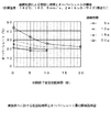
図6は、実施例1に於ける空回転時間とオーバーシュート量の関係説明図である。
この図は、一例として25℃環境で、媒体搬送速度163.5mm/s、媒体搬送間隔L(mm)が50mm、印刷媒体のサイズはレタ−サイズ、媒体方向は横送り、印刷媒体の種類は普通紙、媒体連量は24ポンドの条件で取得した実測データである。
The basic principle of idling time setting by the idling time setting means 116 (FIG. 2) will be described.
FIG. 6 is an explanatory diagram of the relationship between the idling time and the overshoot amount in the first embodiment.
This figure shows, as an example, a 25 ° C. environment, a medium conveyance speed of 163.5 mm / s, a medium conveyance interval L (mm) of 50 mm, a print medium size of a letter size, a medium direction of horizontal feed, and a print medium type The plain paper and the medium continuous amount are actually measured data acquired under the condition of 24 pounds.
図に於いて、縦軸は加熱ローラ102(図2)の表面温度を目標温度Tt=182℃とし、その値からの変動量としてオーバーシュートを表している。又、横軸は、印刷終了後に於ける加熱ローラ102(図2)の空回転時間を表している。更に、パラメータとして印刷ジョブに含まれていた印刷ページ数が5枚(p)、10枚(p)、15枚(p)、50枚(p)と設定している。 In the figure, the vertical axis represents the overshoot as the amount of variation from the target temperature Tt = 182 ° C. with the surface temperature of the heating roller 102 (FIG. 2). The horizontal axis represents the idling time of the heating roller 102 (FIG. 2) after the printing is completed. Further, the number of print pages included in the print job is set as 5 (p), 10 (p), 15 (p), and 50 (p) as a parameter.
オーバーシュート(図5)の限界を目標温度Tt=182℃に対して+25℃とした場合には、5pのグラフをみると、空回転しなくても既に+25℃を満足していることが分かる。10pのグラフをみると、空回転は約1秒で+25℃を満足していることが分かる。15pのグラフをみると、空回転は約6秒で+25℃を満足していることが分かる。50pのグラフをみると、空回転は約13秒で+25℃を満足していることが分かる。この値を種々の条件に基づいて実験的に求める。 When the limit of overshoot (FIG. 5) is set to + 25 ° C. with respect to the target temperature Tt = 182 ° C., it can be seen from the graph of 5p that + 25 ° C. is already satisfied even without idling. . From the graph of 10p, it can be seen that the idle rotation satisfies + 25 ° C. in about 1 second. From the graph of 15p, it can be seen that the idle rotation satisfies + 25 ° C. in about 6 seconds. Looking at the graph of 50p, it can be seen that the idling satisfies + 25 ° C. in about 13 seconds. This value is obtained experimentally based on various conditions.
このようにして求めた印刷ページ数と空回転時間との関係を空回転時間テーブル112−1(図2)としてROM112(図2)に予め格納しておくことになる。その結果、空回転時間設定手段116は、連続印刷数検出手段115から受入れた、印刷ジョブに含まれていたページ数に基づいて、空回転時間テーブル112−1(図2)を検索し、最終ページの印刷終了後における加熱ローラ102の空回転時間を容易に設定することが出来る。即ち、オーバーシュート(図5)の限界を目標温度Tt=182℃に対して+25℃とすると、印刷ジョブに含まれていたページ数が、5pの場合には、空回転0秒となる。10pの場合には、空回転は1秒となる。15pの場合には、空回転は約6秒となる。50pのグラフ場合には、空回転は約13秒となる。本実施例では、15枚未満の連続運転の場合には5秒、15枚以上の連続印刷の場合には15秒の空回転を行うよう設定した。
The relationship between the number of printed pages and the idle rotation time thus obtained is stored in advance in the ROM 112 (FIG. 2) as the idle rotation time table 112-1 (FIG. 2). As a result, the idling
この空回転時間テーブル112−1(図2)に格納する値については、周囲環境毎に求めてもよいし、あるいは又、標準値、例えば25℃に固定して求め、実行時における周囲温度の変化に対しては、予め設定してある係数を乗算することとしても良い。周囲湿度についても同様に扱うことが出来る。 The values stored in the idling time table 112-1 (FIG. 2) may be obtained for each ambient environment, or may be obtained by fixing to a standard value, for example, 25 ° C., and the ambient temperature at the time of execution. The change may be multiplied by a preset coefficient. Ambient humidity can be handled similarly.
再度図2に戻って、外部インタフェース117は、制御部110内の各構成部分と、制御部110外に配設されている各構成部分とを信号接続するインタフェース回路である。
モータ駆動制御部120は、制御部110の制御に基づいて定着器30内部の加熱ローラ102を回転させるモータ駆動信号を生成する部分である。
温度検出部121は、温度センサ31の出力値を温度値に変換する部分である。
温度制御部122は、AC電源126と、加熱ヒータ103との間に配設されるスイッチ125、及びAC電源126と加圧ヒータ101との間に配設されるスイッチ124、とをオン・オフすることによって、加圧ローラ100、及び加熱ローラ102の表面温度を制御する部分である。
Returning again to FIG. 2, the external interface 117 is an interface circuit for signal-connecting each component in the
The motor
The
The
以上説明した本実施例による画像形成装置によって、所定の連続印刷を終了後、後に続く印刷実行にいたるまでの加熱ローラの温度推移について説明する。
図7は、実施例1に於ける次ジョブ投入時の加熱ローラ回転からの温度推移説明図である。
この図は、一例として25℃環境で、媒体搬送速度163.5mm/s、媒体搬送間隔L(mm)が50mm、印刷媒体のサイズはレタ−サイズ、媒体方向は横送り、印刷媒体の種類は普通紙、媒体連量は24ポンドの条件で取得した実測データである。
The temperature transition of the heating roller from the end of predetermined continuous printing to the subsequent printing execution by the image forming apparatus according to the present embodiment described above will be described.
FIG. 7 is an explanatory diagram of temperature transition from the rotation of the heating roller when the next job is input in the first embodiment.
This figure shows, as an example, a 25 ° C. environment, a medium conveyance speed of 163.5 mm / s, a medium conveyance interval L (mm) of 50 mm, a print medium size of a letter size, a medium direction of horizontal feed, and a print medium type The plain paper and the medium continuous amount are actually measured data acquired under the condition of 24 pounds.
図に於いて、縦軸は加熱ローラ102(図2)の表面温度を目標温度Tt=182℃とし、その値からの変動量としてオーバーシュート(℃)を表している。又、横軸は、後に続く印刷ジョブにより加熱ローラ102(図2)の回転開始からの空回転時間を表している。更に、パラメータとして、50Pの連続印刷終了後15秒から回転した場合(空回転有)と、50Pの連続印刷終了後に空回転しなかった場合(空回転無)とを設定している。ここで目標温度+8℃とする。この目標温度+8℃は、後に続く印刷ジョブの印刷起動可能範囲の上限値であり、印刷媒体に付着しているトナーに対して、定着器が過度の熱量を加えることにより印刷画面に発生する画像乱れ(ホットオフセット)の発生閾値である。即ち、この目標温度を+8℃に短時間で到達するということは、後に続く印刷ジョブを短時間で開始することが可能になったことを示している。 In the figure, the vertical axis represents the overshoot (° C.) as the amount of variation from the surface temperature of the heating roller 102 (FIG. 2) with the target temperature Tt = 182 ° C. The horizontal axis represents the idling time from the start of rotation of the heating roller 102 (FIG. 2) by the subsequent print job. Further, as a parameter, a case where the rotation is started from 15 seconds after the end of 50P continuous printing (with idle rotation) and a case where the rotation is not completed after the end of 50P continuous printing (no idle rotation) are set. Here, the target temperature is set to + 8 ° C. This target temperature + 8 ° C. is the upper limit of the print startable range of the subsequent print job, and the image generated on the print screen when the fixing device applies an excessive amount of heat to the toner adhering to the print medium. This is a threshold value for occurrence of disturbance (hot offset). That is, reaching the target temperature to + 8 ° C. in a short time indicates that the subsequent print job can be started in a short time.
図示するように、(空回転有)は、約3秒で目標温度+8℃に到達しているが、(空回転無)は、印刷スピ−ドに係らず、約7秒を必要としている。この図からも明らかなように(空回転有)の効果を認めることが出来る。又、空回転有であっても空回転時間が不十分であった場合について説明する。一例として、図6に於いて、50pであって、空回転を5秒間で停止したものと仮定する。この場合には図6より、約33℃を維持している。この33℃を開始点にして図7へ移すと、図上の点線のようになるものと予想される。即ち、(空回転有)とは大きな差異が予想される。 As shown in the figure, (with idle rotation) reaches the target temperature + 8 ° C. in about 3 seconds, but (without idle rotation) requires about 7 seconds regardless of the printing speed. As is clear from this figure, the effect of (with idle rotation) can be recognized. A case where the idling time is insufficient even when idling is present will be described. As an example, in FIG. 6, it is assumed that the speed is 50p and the idling is stopped in 5 seconds. In this case, about 33 ° C. is maintained from FIG. When this 33 ° C. is used as the starting point and the process moves to FIG. 7, it is expected to be as shown by the dotted line in the figure. That is, a large difference from (with idling) is expected.
以上説明したように、本実施例では、連続印刷数検出手段と、空回転時間設定手段とを備えることによって、加熱ローラの表面温度を考慮して空回転時間を設定することが出来るようになる。その結果、後に続く印刷ジョブの印刷起動時におけるパフォーマンスを向上させるという効果を得る。 As described above, in the present embodiment, the idling time can be set in consideration of the surface temperature of the heating roller by including the continuous printing number detecting unit and the idling time setting unit. . As a result, an effect of improving the performance at the time of starting printing of the subsequent print job is obtained.
本実施例では、印刷媒体の厚さによって最適な空回転時間が異なってくることを認識し、印刷媒体の厚さによって空回転時間を補正することとする。
図8は、実施例2の空回転時間制御系統ブロック図である。
図に示すように、空回転時間制御系統230は、制御部210と、モータ駆動制御部120と、温度検出部121と、温度制御部122と、媒体厚さセンサ217を備える。以下に実施例1との相違部分のみについて詳細に説明する。実施例1と同様の部分については実施例1と同一の符号を付して説明を省略する。尚、実施例2による画像形成装置の概略構成については空転回転時間制御系統が異なるのみで、他の部分は全く同じなので説明を省略する。
In this embodiment, it is recognized that the optimum idling time varies depending on the thickness of the print medium, and the idling time is corrected based on the thickness of the print medium.
FIG. 8 is an idle rotation time control system block diagram of the second embodiment.
As shown in the figure, the idling time control system 230 includes a
制御部210は、CPU211と、ROM212と、RAM113と、タイマ114と、連続印刷数検出手段115と、空回転時間設定手段216と、外部インタフェース117とを有し、印刷終了ページを検出し、当該印刷ジョブに含まれていた印刷枚数と、印刷媒体の厚さとを検出し、この印刷枚数と印刷媒体の厚さに応じて加圧ローラ100、及び加熱ローラ102の空回転時間を設定し、両ローラの温度を適切に制御することによって後に続く印刷ジョブの印刷起動時におけるパフォーマンスを向上させる部分である。
The
CPU211は、ROM212に予め格納されている制御プログラムを実行することによって画像形成装置1(図1)全体を制御するマイクロプロセッサである。特に、本実施例では、ROM212に予め格納されている所定の制御データを用い、所定の制御プログラムを実行することによって、連続印刷数検出手段115と空回転時間設定手段216とを起動させる部分である。
The
ROM212は、CPU211が実行することによって画像形成装置1(図1)全体を制御する制御プログラム及びそれに必要な制御データを予め格納するリードオンリーメモリである。本実施例では、特にCPU211が実行することによって連続印刷数検出手段115と空回転時間設定手段216とを起動させる制御プログラム、及び空回転時間テーブル112−1、及び空回転時間補正値テーブル212−1(後述する)とを格納するリードオンリーメモリである。
The
空回転時間設定手段216は、連続印刷数検出手段115から受入れた印刷ジョブに含まれていたページ数基づいて、最終ページの印刷終了後における加熱ローラ102の空回転時間を設定する部分である。更に、媒体厚さセンサ217から受入れた印刷媒体の厚さに基づいて空回転時間を補正する部分である。ここで、最初に印刷媒体の厚さが異なることによって加熱ローラ102の空回転による効果に与える影響について説明する。
The idling
図9は、実施例2に於いて紙厚を変えて空回転を実施した場合のタイムチャートである。
この図はパラメータを紙厚110ミクロンと紙厚100ミクロンに設定し、空回転した場合のタイムチャートである。
連続印刷の場合、最初の印刷媒体の先端部が目標温度Ttに調節された加熱ローラ102(図8)と加圧ローラ100が圧接されたニップ部104(図8)を通過する際、定着に必要な熱量を加熱ローラ102(図8)と加圧ローラ100から奪うために、加熱ローラ102(図8)の表面温度が低下する(区間a)。ここでは、紙厚110ミクロンの方が紙厚100ミクロンに比較して温度が低下する。このとき温度制御部122(図8)は、加熱ローラ102(図8)の表面温度を目標温度Ttに近づけようとして、加熱ヒータ103(図8)、及び必要に応じて加圧ヒータ101(図8)を制御する。この制御はAC電源126と、加熱ヒータ103(図8)との間に配設されるスイッチ125、及びAC電源126と加圧ヒータ101(図8)との間に配設されるスイッチ124、とをオン・オフすることによって実行される。
FIG. 9 is a time chart when the idle rotation is performed with the paper thickness changed in the second embodiment.
This figure is a time chart when the parameters are set to a paper thickness of 110 microns and a paper thickness of 100 microns, and idling.
In the case of continuous printing, when the leading edge of the first print medium passes through the heating roller 102 (FIG. 8) adjusted to the target temperature Tt and the nip 104 (FIG. 8) where the
加熱ローラ102(図8)の表面温度が目標温度Ttに近づいた後、一定の温度に制御される(区間b)。この区間bでは、加熱ローラ102(図8)による印刷媒体への投入熱量と、印刷媒体が搬送されながら吸収する熱量とのバランスが確保される。ここでは、紙厚110ミクロンと紙厚100ミクロンとは同一である。区間bの最後では、連続印刷の最後の印刷媒体の後端部がニップ部104(図8)を通過し、媒体検出センサ52(図8)を通過したことを連続印刷数検出手段115(図8)が検出すると、加熱ヒータ103(図8)、及び加圧ヒータ101(図8)は、温度制御部122(図8)によって強制的にオフされる。そのタイミングを図中△のタイミングとする。 After the surface temperature of the heating roller 102 (FIG. 8) approaches the target temperature Tt, it is controlled to a constant temperature (section b). In this section b, a balance is ensured between the amount of heat input to the print medium by the heating roller 102 (FIG. 8) and the amount of heat absorbed while the print medium is conveyed. Here, the paper thickness of 110 microns and the paper thickness of 100 microns are the same. At the end of the section b, it is determined that the trailing edge of the last print medium of continuous printing has passed the nip portion 104 (FIG. 8) and has passed the medium detection sensor 52 (FIG. 8). 8), the heater 103 (FIG. 8) and the pressure heater 101 (FIG. 8) are forcibly turned off by the temperature controller 122 (FIG. 8). The timing is assumed to be a time Δ in the figure.
△よりも若干遅れたて時点から一定時間(区間c1の間)空回転させる。ここでは区間c1を15秒に設定している。15秒空回転させることによって加熱ローラ102(図2)が投入していた熱量の一部は外部に放出される。この区間c1ではまだ、紙厚110ミクロンと紙厚100ミクロンとの差は明確にはならない。区間c1終了後、加熱ローラ102(図8)、及び加圧ローラ100(図8)が回転停止される。この時点から区間cが開始する。この区間cでは、加熱ローラ102(図8)が投入していた熱量の放出先が無くなり、加熱ローラ102(図8)の表面温度が急激に所定値まで上昇する。ここでは、紙厚110ミクロンのオーバーシュートY4の方が紙厚100ミクロンのオーバーシュートY3に比較して大きくなる。 A little later than Δ, the vehicle is idled for a certain time (during section c1). Here, the section c1 is set to 15 seconds. By idling for 15 seconds, a part of the heat quantity input by the heating roller 102 (FIG. 2) is released to the outside. In this section c1, the difference between the paper thickness of 110 microns and the paper thickness of 100 microns is not yet clear. After the section c1, the rotation of the heating roller 102 (FIG. 8) and the pressure roller 100 (FIG. 8) is stopped. From this point, section c starts. In this section c, the amount of heat released from the heating roller 102 (FIG. 8) disappears, and the surface temperature of the heating roller 102 (FIG. 8) rises rapidly to a predetermined value. Here, the overshoot Y4 having a paper thickness of 110 microns is larger than the overshoot Y3 having a paper thickness of 100 microns.
図10は、実施例2に於いて空回転時間を変えて実施した場合のタイムチャートである。
この図も図9と同様にパラメータを紙厚110ミクロンと紙厚100ミクロンに設定する。
この図に於いて区間a、区間b、及び区間c1は、図9と同様なので説明を省略し、区間c2、区間c、について説明する。ここで区間c1は15秒に、区間c2は5秒にそれぞれ設定している。紙厚100ミクロンでは、区間c1終了後、加熱ローラ102(図8)、及び加圧ローラ100(図8)が回転停止される。この時点から紙厚100ミクロンでは区間cが開始する。この区間cでは、加熱ローラ102(図8)が投入していた熱量の放出先が無くなり、加熱ローラ102(図8)の表面温度が急激にY3まで上昇する。
FIG. 10 is a time chart when the idling rotation time is changed in the second embodiment.
In this figure, as in FIG. 9, the parameters are set to a paper thickness of 110 microns and a paper thickness of 100 microns.
In this figure, the section a, the section b, and the section c1 are the same as those in FIG. 9, and thus the description thereof is omitted, and the section c2 and the section c are described. Here, the section c1 is set to 15 seconds, and the section c2 is set to 5 seconds. When the paper thickness is 100 microns, the heating roller 102 (FIG. 8) and the pressure roller 100 (FIG. 8) stop rotating after the end of the section c1. From this point, section c starts when the paper thickness is 100 microns. In this section c, the amount of heat released by the heating roller 102 (FIG. 8) disappears, and the surface temperature of the heating roller 102 (FIG. 8) rises rapidly to Y3.
一方、紙厚110ミクロンでは、区間c2でまだ空回転が継続され、区間c2終了後に加熱ローラ102(図8)、及び加圧ローラ100(図8)が回転停止される。この時点から紙厚110ミクロンでは区間cが開始する。この区間cでは、加熱ローラ102(図8)が投入していた熱量の放出先が無くなり、加熱ローラ102(図8)の表面温度が急激にY5まで上昇する。ここでは、印刷媒体の紙厚が通常使用している紙厚よりも厚く成ると、他の条件が全て同じであってもオーバーシュート(℃)が大きくなってしまうことを表している。しかし、空回転時間を補正することによってオーバーシュート(℃)を通常の値に近似させることが出来ることに留意すべきである。 On the other hand, when the paper thickness is 110 microns, the idling rotation is still continued in the section c2, and the heating roller 102 (FIG. 8) and the pressure roller 100 (FIG. 8) are stopped after the section c2. From this point, section c starts at a paper thickness of 110 microns. In this section c, the amount of heat released by the heating roller 102 (FIG. 8) disappears, and the surface temperature of the heating roller 102 (FIG. 8) rises rapidly to Y5. Here, when the paper thickness of the printing medium becomes thicker than the paper thickness that is normally used, the overshoot (° C.) increases even if all other conditions are the same. However, it should be noted that the overshoot (° C.) can be approximated to a normal value by correcting the idling time.
次に印刷媒体の紙厚変化に対応する空回転時間の補正方法について説明する。
図11は、媒体厚変化によるオーバーシュート(℃)変化の説明図である。
この図は、媒体厚さセンサ217(図8)による計測結果が100ミクロンの印刷媒体と、計測結果が110ミクロンの印刷媒体とを使って50枚連続印刷し、連続印刷後の空回転を15秒実施した場合と、20秒実施した場合におけるオーバーシュート(℃)を実測した値を表している。この計測条件は、媒体搬送速度163.5mm/sで、各々4印刷ジョブについて実測している。図に示すように、紙厚100ミクロン、空回転15秒ではオーバーシュート27.5(℃)であり、紙厚110ミクロン、空回転15秒ではオーバーシュート29.3(℃)であり、紙厚100ミクロン、空回転20秒ではオーバーシュート21.0(℃)であり、紙厚110ミクロン、空回転20秒ではオーバーシュート23.0(℃)である。
Next, a method for correcting the idling time corresponding to the change in the paper thickness of the print medium will be described.
FIG. 11 is an explanatory diagram of changes in overshoot (° C.) due to changes in the medium thickness.
This figure shows that 50 sheets are continuously printed using a printing medium with a measurement result of 100 microns by the medium thickness sensor 217 (FIG. 8) and a printing medium with a measurement result of 110 microns, and the idling after the continuous printing is 15 times. The measured value of the overshoot (° C.) in the case of carrying out for 2 seconds and in the case of carrying out for 20 seconds is shown. The measurement conditions were actually measured for four print jobs at a medium conveyance speed of 163.5 mm / s. As shown in the figure, when the paper thickness is 100 microns and the idle rotation is 15 seconds, the overshoot is 27.5 (° C), and when the paper thickness is 110 microns and the idle rotation is 15 seconds, the overshoot is 29.3 (° C). The overshoot is 21.0 (° C.) at 100 microns and idling 20 seconds, and the overshoot is 23.0 (° C.) at
図12は、媒体厚変化に対応した空回転時間補正原理説明図である。
この図は、上記図11の測定結果を空回転時間をパラメータにしてグラフ化した図である。図の縦軸はオーバーシュート(℃)を表し、横軸は媒体厚さ(μm)を表している。図中2本の実線は、図11の計測結果を表したグラフ(直線近似)である。即ち、○印のグラフは、実測値に基づく空回転15秒のグラフであり、×印のグラフは、実測値に基づく空回転20秒のグラフである。ここで空回転15秒のグラフ(○印)と、空回転20秒のグラフ(×印)との間に等間隔に4本のグラフを挿入すると、上から順に空回転16秒のグラフ、空回転17秒のグラフ、空回転18秒のグラフ、空回転19秒のグラフを、それぞれ想定(近似)することが出来る。
FIG. 12 is an explanatory diagram of the idling time correction principle corresponding to the change in the medium thickness.
This figure is a graph of the measurement result of FIG. 11 described above with the idling time as a parameter. In the figure, the vertical axis represents overshoot (° C.), and the horizontal axis represents medium thickness (μm). The two solid lines in the figure are graphs (linear approximation) showing the measurement results in FIG. That is, the circled graph is a graph of idling 15 seconds based on the actual measurement value, and the x mark is a graph of idling 20 seconds based on the actual measurement value. If four graphs are inserted at equal intervals between a graph of 15 seconds of idle rotation (circle) and a graph of 20 seconds of idle rotation (×), a graph of 16 seconds of idle rotation, A graph of 17 seconds of rotation, a graph of 18 seconds of idle rotation, and a graph of 19 seconds of idle rotation can be assumed (approximated), respectively.
これらの想定グラフら、以下の補正が可能になる。一例として紙厚100ミクロンでオーバーシュートを25℃にする場合には空回転時間を約17秒(図中P0点)に設定することになる。又、紙厚105ミクロンに変化した場合には空回転時間を約18秒(図中P1点)に補正し、紙厚110ミクロンに変化した場合には空回転時間を約19秒(図中P2点)に補正し、紙厚95ミクロンに変化した場合には空回転時間を約16秒(図中P3点)に補正することによって媒体厚変化に対応した空回転時間補正が可能になる。即ち、この補正値を上記空回転時間補正値テーブル212−1に予め格納することになる。 These assumption graphs can be corrected as follows. As an example, when the paper thickness is 100 microns and the overshoot is 25 ° C., the idling time is set to about 17 seconds (P0 point in the figure). When the paper thickness changes to 105 microns, the idling time is corrected to about 18 seconds (point P1 in the figure), and when the paper thickness changes to 110 microns, the idling time is about 19 seconds (P2 in the figure). When the paper thickness is changed to 95 microns, the idling time is corrected to about 16 seconds (point P3 in the figure), thereby enabling idling time correction corresponding to the change in the media thickness. That is, this correction value is stored in advance in the idling time correction value table 212-1.
再度図8に戻って、媒体厚さセンサ217は、印刷媒体の厚さを計測するセンサである。通常、微小変位センサなどが用いられる。このセンサは、印刷媒体の厚さを計測できるものであればどのようなセンサであっても良い。更に、媒体カセット3(図1)に収納する前にオペレ−タが印刷媒体の厚さを手作業で計測し、その厚さを外部インタフェース117(図8)を介して信号入力しても良い。
Returning to FIG. 8 again, the
以上説明したように、実施例2によれば、連続印刷中に印刷媒体の厚さを検知し、連続印刷後の空回転時間を厚さに応じて変化させることによって、印刷媒体の厚さが厚い場合であっても、あるいは又薄い場合であっても、オーバーシュートを正確に制御することが可能になるので上記実施例1の効果に加えて、より一層、後に続く印刷ジョブの印刷起動時のパフォーマンスを向上させることが出来るという効果を得る。 As described above, according to the second embodiment, the thickness of the print medium is detected by detecting the thickness of the print medium during continuous printing and changing the idling time after the continuous printing according to the thickness. Even if it is thick or thin, it is possible to accurately control overshoot. Therefore, in addition to the effect of the first embodiment, the print job of the subsequent print job is started further. The effect that the performance of can be improved.
以上の説明では、本発明をプリンタに適用した場合に限定して説明したが、本発明は、この例に限定されるものでは無い。即ち、ファクシミリ装置や、複写機などにも適用可能である。 In the above description, the present invention is limited to the case where the present invention is applied to a printer. However, the present invention is not limited to this example. That is, the present invention can be applied to a facsimile machine and a copying machine.
30 定着器
31 サ−ミスタ
52 媒体検出センサ
100 加圧ローラ
101 加圧ヒータ
102 加熱ローラ
103 加熱ヒータ
104 ニップ部
105 モータ
110 制御部
111 CPU
112 ROM
112−1 空回転時間テーブル
113 RAM
114 タイマ
115 連続印刷数検出手段
116 空回転時間設定手段
117 外部インタフェース
120 モータ駆動制御部
121 温度検出部
122 温度制御部
124 スイッチ
125 スイッチ
DESCRIPTION OF
112 ROM
112-1 idling time table 113 RAM
114
Claims (4)
前記媒体検出手段を監視し、印刷媒体が所定の間隔より小さく搬送されながら連続して印刷された印刷数を検出する連続印刷数検出手段と、
該連続印刷数検出手段により検出された印刷数に応じて前記過熱部材の空回転時間を設定する空回転時間設定手段とを備えることを特徴とする画像形成装置。 A heating member that is disposed on the medium conveyance path and executes a fixing process of the print medium, a temperature control unit that controls energization of the heating member, a rotation drive control unit that controls rotation of the heating member, and the medium conveyance An image forming apparatus capable of idle rotation of the heating member for a predetermined time while stopping energization after the printing medium has passed through the heating member. And
Monitoring the medium detection means, and detecting a continuous print number detection means for detecting the number of prints continuously printed while the print medium is conveyed smaller than a predetermined interval;
An image forming apparatus comprising: an idling time setting unit configured to set an idling time of the overheated member according to the number of prints detected by the continuous printing number detecting unit.
前記空回転時間設定手段は、該空回転時間情報記憶領域を検索し、前記加熱部材の空回転時間を設定することを特徴とする請求項1に記載の画像形成装置。 An idle rotation time information storage area for storing in advance information related to the number of continuously printed prints and the idle rotation time of the heating member;
2. The image forming apparatus according to claim 1, wherein the idling time setting unit searches the idling time information storage area and sets the idling time of the heating member.
The idling time information storage area further stores medium thickness correction information for correcting the related information between the number of continuously printed prints and the idling time of the heating member based on the thickness of the printing medium. The image forming apparatus according to claim 2.
Priority Applications (1)
| Application Number | Priority Date | Filing Date | Title |
|---|---|---|---|
| JP2005186250A JP2007003992A (en) | 2005-06-27 | 2005-06-27 | Image forming apparatus |
Applications Claiming Priority (1)
| Application Number | Priority Date | Filing Date | Title |
|---|---|---|---|
| JP2005186250A JP2007003992A (en) | 2005-06-27 | 2005-06-27 | Image forming apparatus |
Publications (2)
| Publication Number | Publication Date |
|---|---|
| JP2007003992A true JP2007003992A (en) | 2007-01-11 |
| JP2007003992A5 JP2007003992A5 (en) | 2008-04-10 |
Family
ID=37689659
Family Applications (1)
| Application Number | Title | Priority Date | Filing Date |
|---|---|---|---|
| JP2005186250A Pending JP2007003992A (en) | 2005-06-27 | 2005-06-27 | Image forming apparatus |
Country Status (1)
| Country | Link |
|---|---|
| JP (1) | JP2007003992A (en) |
Cited By (7)
| Publication number | Priority date | Publication date | Assignee | Title |
|---|---|---|---|---|
| JP2009048074A (en) * | 2007-08-22 | 2009-03-05 | Ricoh Co Ltd | Fixing device and image forming apparatus |
| JP2009128747A (en) * | 2007-11-27 | 2009-06-11 | Oki Data Corp | Image forming apparatus |
| JP2012230435A (en) * | 2012-08-29 | 2012-11-22 | Ricoh Co Ltd | Fixing device and image forming apparatus |
| US20130202322A1 (en) * | 2012-01-27 | 2013-08-08 | Takumi Waida | Fixing device and image forming apparatus |
| CN103376719A (en) * | 2012-04-25 | 2013-10-30 | 京瓷办公信息系统株式会社 | Image forming apparatus |
| US8731423B2 (en) | 2011-01-19 | 2014-05-20 | Kabushiki Kaisha Toshiba | Image forming apparatus and control device and control method of fixing device |
| US9042761B2 (en) | 2012-02-09 | 2015-05-26 | Ricoh Company, Limited | Fixing device and image forming apparatus |
Citations (18)
| Publication number | Priority date | Publication date | Assignee | Title |
|---|---|---|---|---|
| JPH0455256A (en) * | 1990-06-21 | 1992-02-21 | Brother Ind Ltd | Image formation equipment |
| JPH06348175A (en) * | 1993-06-10 | 1994-12-22 | Canon Inc | Image heating device |
| JPH09325540A (en) * | 1996-06-06 | 1997-12-16 | Canon Inc | Image forming device |
| JPH1173055A (en) * | 1997-08-28 | 1999-03-16 | Canon Inc | Control method for image forming apparatus having heat fixing device |
| JPH11194661A (en) * | 1997-10-29 | 1999-07-21 | Minolta Co Ltd | Fixing device and image forming device using the device |
| JPH11249489A (en) * | 1998-02-27 | 1999-09-17 | Canon Inc | Image forming device |
| JPH11258943A (en) * | 1998-03-13 | 1999-09-24 | Ricoh Co Ltd | Image forming device |
| JP2000242133A (en) * | 1999-02-22 | 2000-09-08 | Kyocera Corp | Fixing temperature control method for electrophotographic device |
| JP2002214961A (en) * | 2001-01-16 | 2002-07-31 | Canon Inc | Heat fixing device and image forming device having the same |
| JP2002278350A (en) * | 2001-03-15 | 2002-09-27 | Canon Inc | Heating device and image forming device |
| JP2004054246A (en) * | 2002-05-30 | 2004-02-19 | Canon Inc | Image forming apparatus and image forming method |
| JP2004101682A (en) * | 2002-09-06 | 2004-04-02 | Canon Inc | Image forming apparatus |
| JP2004099280A (en) * | 2002-09-11 | 2004-04-02 | Riso Kagaku Corp | Paper carrying device |
| JP2004333913A (en) * | 2003-05-08 | 2004-11-25 | Ricoh Co Ltd | Image forming apparatus |
| JP2005024715A (en) * | 2003-06-30 | 2005-01-27 | Ricoh Co Ltd | Image forming apparatus |
| JP2005043668A (en) * | 2003-07-22 | 2005-02-17 | Murata Mach Ltd | Image forming apparatus |
| JP2005128380A (en) * | 2003-10-27 | 2005-05-19 | Ricoh Co Ltd | Fixing device, image forming apparatus and toner used in the same |
| JP2005134745A (en) * | 2003-10-31 | 2005-05-26 | Canon Inc | Image forming apparatus and toner image transfer method |
-
2005
- 2005-06-27 JP JP2005186250A patent/JP2007003992A/en active Pending
Patent Citations (18)
| Publication number | Priority date | Publication date | Assignee | Title |
|---|---|---|---|---|
| JPH0455256A (en) * | 1990-06-21 | 1992-02-21 | Brother Ind Ltd | Image formation equipment |
| JPH06348175A (en) * | 1993-06-10 | 1994-12-22 | Canon Inc | Image heating device |
| JPH09325540A (en) * | 1996-06-06 | 1997-12-16 | Canon Inc | Image forming device |
| JPH1173055A (en) * | 1997-08-28 | 1999-03-16 | Canon Inc | Control method for image forming apparatus having heat fixing device |
| JPH11194661A (en) * | 1997-10-29 | 1999-07-21 | Minolta Co Ltd | Fixing device and image forming device using the device |
| JPH11249489A (en) * | 1998-02-27 | 1999-09-17 | Canon Inc | Image forming device |
| JPH11258943A (en) * | 1998-03-13 | 1999-09-24 | Ricoh Co Ltd | Image forming device |
| JP2000242133A (en) * | 1999-02-22 | 2000-09-08 | Kyocera Corp | Fixing temperature control method for electrophotographic device |
| JP2002214961A (en) * | 2001-01-16 | 2002-07-31 | Canon Inc | Heat fixing device and image forming device having the same |
| JP2002278350A (en) * | 2001-03-15 | 2002-09-27 | Canon Inc | Heating device and image forming device |
| JP2004054246A (en) * | 2002-05-30 | 2004-02-19 | Canon Inc | Image forming apparatus and image forming method |
| JP2004101682A (en) * | 2002-09-06 | 2004-04-02 | Canon Inc | Image forming apparatus |
| JP2004099280A (en) * | 2002-09-11 | 2004-04-02 | Riso Kagaku Corp | Paper carrying device |
| JP2004333913A (en) * | 2003-05-08 | 2004-11-25 | Ricoh Co Ltd | Image forming apparatus |
| JP2005024715A (en) * | 2003-06-30 | 2005-01-27 | Ricoh Co Ltd | Image forming apparatus |
| JP2005043668A (en) * | 2003-07-22 | 2005-02-17 | Murata Mach Ltd | Image forming apparatus |
| JP2005128380A (en) * | 2003-10-27 | 2005-05-19 | Ricoh Co Ltd | Fixing device, image forming apparatus and toner used in the same |
| JP2005134745A (en) * | 2003-10-31 | 2005-05-26 | Canon Inc | Image forming apparatus and toner image transfer method |
Cited By (12)
| Publication number | Priority date | Publication date | Assignee | Title |
|---|---|---|---|---|
| JP2009048074A (en) * | 2007-08-22 | 2009-03-05 | Ricoh Co Ltd | Fixing device and image forming apparatus |
| JP2009128747A (en) * | 2007-11-27 | 2009-06-11 | Oki Data Corp | Image forming apparatus |
| JP4617345B2 (en) * | 2007-11-27 | 2011-01-26 | 株式会社沖データ | Image forming apparatus |
| US8731423B2 (en) | 2011-01-19 | 2014-05-20 | Kabushiki Kaisha Toshiba | Image forming apparatus and control device and control method of fixing device |
| US20130202322A1 (en) * | 2012-01-27 | 2013-08-08 | Takumi Waida | Fixing device and image forming apparatus |
| US8805225B2 (en) * | 2012-01-27 | 2014-08-12 | Ricoh Company, Limited | Fixing device and image forming apparatus |
| US9042761B2 (en) | 2012-02-09 | 2015-05-26 | Ricoh Company, Limited | Fixing device and image forming apparatus |
| US9141047B2 (en) | 2012-02-09 | 2015-09-22 | Ricoh Company, Limited | Fixing device and image forming apparatus |
| CN103376719A (en) * | 2012-04-25 | 2013-10-30 | 京瓷办公信息系统株式会社 | Image forming apparatus |
| JP2013228563A (en) * | 2012-04-25 | 2013-11-07 | Kyocera Document Solutions Inc | Image forming apparatus |
| US9031438B2 (en) | 2012-04-25 | 2015-05-12 | Kyocera Document Solutions Inc. | Image forming apparatus |
| JP2012230435A (en) * | 2012-08-29 | 2012-11-22 | Ricoh Co Ltd | Fixing device and image forming apparatus |
Similar Documents
| Publication | Publication Date | Title |
|---|---|---|
| KR20080084226A (en) | Image forming apparatus and control method thereof | |
| JP2007003992A (en) | Image forming apparatus | |
| JP5054868B2 (en) | Image forming apparatus | |
| US10514649B2 (en) | Image forming apparatus | |
| US8270858B2 (en) | Image forming device to determine paper width and image forming method thereof | |
| CN111332835B (en) | Image forming apparatus and computer-readable recording medium storing control program | |
| JP5089119B2 (en) | Image forming apparatus | |
| JP4972985B2 (en) | Image forming apparatus | |
| JP2010113237A (en) | Image forming apparatus and program | |
| JP2008139411A (en) | Image forming apparatus | |
| JP2015208890A (en) | Image formation apparatus | |
| JP4821215B2 (en) | Image recording device | |
| JP4605230B2 (en) | Image forming apparatus | |
| JP2006065016A (en) | Image forming apparatus | |
| JP2007310129A (en) | Image forming apparatus | |
| JP2009048074A (en) | Fixing device and image forming apparatus | |
| JP2020067472A (en) | Image forming apparatus | |
| JP2005024667A (en) | Image forming apparatus | |
| JP6841065B2 (en) | Fixing device, image forming device, abnormality occurrence judgment device, and program | |
| JP5977189B2 (en) | Image forming apparatus and image forming apparatus control method | |
| JP2014167618A (en) | Image forming apparatus | |
| JP6897631B2 (en) | Fixing device and image forming device | |
| US11747755B2 (en) | Image forming apparatus having controller for setting cooling threshold according to sheet size | |
| JP7183755B2 (en) | image forming device | |
| JP2006047398A (en) | Image forming apparatus |
Legal Events
| Date | Code | Title | Description |
|---|---|---|---|
| A521 | Written amendment |
Free format text: JAPANESE INTERMEDIATE CODE: A523 Effective date: 20080220 |
|
| A621 | Written request for application examination |
Free format text: JAPANESE INTERMEDIATE CODE: A621 Effective date: 20080220 |
|
| A977 | Report on retrieval |
Free format text: JAPANESE INTERMEDIATE CODE: A971007 Effective date: 20101118 |
|
| A131 | Notification of reasons for refusal |
Free format text: JAPANESE INTERMEDIATE CODE: A131 Effective date: 20101214 |
|
| A521 | Written amendment |
Free format text: JAPANESE INTERMEDIATE CODE: A523 Effective date: 20110209 |
|
| A131 | Notification of reasons for refusal |
Free format text: JAPANESE INTERMEDIATE CODE: A131 Effective date: 20110524 |
|
| A521 | Written amendment |
Free format text: JAPANESE INTERMEDIATE CODE: A523 Effective date: 20110720 |
|
| A02 | Decision of refusal |
Free format text: JAPANESE INTERMEDIATE CODE: A02 Effective date: 20110913 |