JP2006523512A - Assembly for supporting and adjusting the lower leg and foot - Google Patents
Assembly for supporting and adjusting the lower leg and foot Download PDFInfo
- Publication number
- JP2006523512A JP2006523512A JP2006510007A JP2006510007A JP2006523512A JP 2006523512 A JP2006523512 A JP 2006523512A JP 2006510007 A JP2006510007 A JP 2006510007A JP 2006510007 A JP2006510007 A JP 2006510007A JP 2006523512 A JP2006523512 A JP 2006523512A
- Authority
- JP
- Japan
- Prior art keywords
- platform
- support assembly
- foot
- assembly
- support
- Prior art date
- Legal status (The legal status is an assumption and is not a legal conclusion. Google has not performed a legal analysis and makes no representation as to the accuracy of the status listed.)
- Pending
Links
Images


Classifications
-
- A—HUMAN NECESSITIES
- A61—MEDICAL OR VETERINARY SCIENCE; HYGIENE
- A61H—PHYSICAL THERAPY APPARATUS, e.g. DEVICES FOR LOCATING OR STIMULATING REFLEX POINTS IN THE BODY; ARTIFICIAL RESPIRATION; MASSAGE; BATHING DEVICES FOR SPECIAL THERAPEUTIC OR HYGIENIC PURPOSES OR SPECIFIC PARTS OF THE BODY
- A61H1/00—Apparatus for passive exercising; Vibrating apparatus ; Chiropractic devices, e.g. body impacting devices, external devices for briefly extending or aligning unbroken bones
- A61H1/02—Stretching or bending or torsioning apparatus for exercising
- A61H1/0218—Drawing-out devices
- A61H1/0222—Traction tables
-
- A—HUMAN NECESSITIES
- A61—MEDICAL OR VETERINARY SCIENCE; HYGIENE
- A61G—TRANSPORT, PERSONAL CONVEYANCES, OR ACCOMMODATION SPECIALLY ADAPTED FOR PATIENTS OR DISABLED PERSONS; OPERATING TABLES OR CHAIRS; CHAIRS FOR DENTISTRY; FUNERAL DEVICES
- A61G13/00—Operating tables; Auxiliary appliances therefor
- A61G13/009—Physiotherapeutic tables, beds or platforms; Chiropractic or osteopathic tables
-
- A—HUMAN NECESSITIES
- A61—MEDICAL OR VETERINARY SCIENCE; HYGIENE
- A61G—TRANSPORT, PERSONAL CONVEYANCES, OR ACCOMMODATION SPECIALLY ADAPTED FOR PATIENTS OR DISABLED PERSONS; OPERATING TABLES OR CHAIRS; CHAIRS FOR DENTISTRY; FUNERAL DEVICES
- A61G13/00—Operating tables; Auxiliary appliances therefor
- A61G13/10—Parts, details or accessories
- A61G13/12—Rests specially adapted therefor; Arrangements of patient-supporting surfaces
- A61G13/1205—Rests specially adapted therefor; Arrangements of patient-supporting surfaces for specific parts of the body
- A61G13/1245—Knees, upper or lower legs
-
- A—HUMAN NECESSITIES
- A61—MEDICAL OR VETERINARY SCIENCE; HYGIENE
- A61G—TRANSPORT, PERSONAL CONVEYANCES, OR ACCOMMODATION SPECIALLY ADAPTED FOR PATIENTS OR DISABLED PERSONS; OPERATING TABLES OR CHAIRS; CHAIRS FOR DENTISTRY; FUNERAL DEVICES
- A61G13/00—Operating tables; Auxiliary appliances therefor
- A61G13/10—Parts, details or accessories
- A61G13/12—Rests specially adapted therefor; Arrangements of patient-supporting surfaces
- A61G13/1205—Rests specially adapted therefor; Arrangements of patient-supporting surfaces for specific parts of the body
- A61G13/1255—Shoulders
-
- A—HUMAN NECESSITIES
- A61—MEDICAL OR VETERINARY SCIENCE; HYGIENE
- A61H—PHYSICAL THERAPY APPARATUS, e.g. DEVICES FOR LOCATING OR STIMULATING REFLEX POINTS IN THE BODY; ARTIFICIAL RESPIRATION; MASSAGE; BATHING DEVICES FOR SPECIAL THERAPEUTIC OR HYGIENIC PURPOSES OR SPECIFIC PARTS OF THE BODY
- A61H1/00—Apparatus for passive exercising; Vibrating apparatus ; Chiropractic devices, e.g. body impacting devices, external devices for briefly extending or aligning unbroken bones
- A61H1/02—Stretching or bending or torsioning apparatus for exercising
- A61H1/0218—Drawing-out devices
- A61H1/0229—Drawing-out devices by reducing gravity forces normally applied to the body, e.g. by lifting or hanging the body or part of it
-
- A—HUMAN NECESSITIES
- A61—MEDICAL OR VETERINARY SCIENCE; HYGIENE
- A61H—PHYSICAL THERAPY APPARATUS, e.g. DEVICES FOR LOCATING OR STIMULATING REFLEX POINTS IN THE BODY; ARTIFICIAL RESPIRATION; MASSAGE; BATHING DEVICES FOR SPECIAL THERAPEUTIC OR HYGIENIC PURPOSES OR SPECIFIC PARTS OF THE BODY
- A61H1/00—Apparatus for passive exercising; Vibrating apparatus ; Chiropractic devices, e.g. body impacting devices, external devices for briefly extending or aligning unbroken bones
- A61H1/02—Stretching or bending or torsioning apparatus for exercising
- A61H1/0237—Stretching or bending or torsioning apparatus for exercising for the lower limbs
-
- A—HUMAN NECESSITIES
- A61—MEDICAL OR VETERINARY SCIENCE; HYGIENE
- A61G—TRANSPORT, PERSONAL CONVEYANCES, OR ACCOMMODATION SPECIALLY ADAPTED FOR PATIENTS OR DISABLED PERSONS; OPERATING TABLES OR CHAIRS; CHAIRS FOR DENTISTRY; FUNERAL DEVICES
- A61G13/00—Operating tables; Auxiliary appliances therefor
- A61G13/10—Parts, details or accessories
- A61G13/12—Rests specially adapted therefor; Arrangements of patient-supporting surfaces
- A61G13/1205—Rests specially adapted therefor; Arrangements of patient-supporting surfaces for specific parts of the body
- A61G13/121—Head or neck
-
- A—HUMAN NECESSITIES
- A61—MEDICAL OR VETERINARY SCIENCE; HYGIENE
- A61G—TRANSPORT, PERSONAL CONVEYANCES, OR ACCOMMODATION SPECIALLY ADAPTED FOR PATIENTS OR DISABLED PERSONS; OPERATING TABLES OR CHAIRS; CHAIRS FOR DENTISTRY; FUNERAL DEVICES
- A61G13/00—Operating tables; Auxiliary appliances therefor
- A61G13/10—Parts, details or accessories
- A61G13/12—Rests specially adapted therefor; Arrangements of patient-supporting surfaces
- A61G13/1205—Rests specially adapted therefor; Arrangements of patient-supporting surfaces for specific parts of the body
- A61G13/1225—Back
-
- A—HUMAN NECESSITIES
- A61—MEDICAL OR VETERINARY SCIENCE; HYGIENE
- A61G—TRANSPORT, PERSONAL CONVEYANCES, OR ACCOMMODATION SPECIALLY ADAPTED FOR PATIENTS OR DISABLED PERSONS; OPERATING TABLES OR CHAIRS; CHAIRS FOR DENTISTRY; FUNERAL DEVICES
- A61G13/00—Operating tables; Auxiliary appliances therefor
- A61G13/10—Parts, details or accessories
- A61G13/12—Rests specially adapted therefor; Arrangements of patient-supporting surfaces
- A61G13/1205—Rests specially adapted therefor; Arrangements of patient-supporting surfaces for specific parts of the body
- A61G13/1235—Arms
-
- A—HUMAN NECESSITIES
- A61—MEDICAL OR VETERINARY SCIENCE; HYGIENE
- A61G—TRANSPORT, PERSONAL CONVEYANCES, OR ACCOMMODATION SPECIALLY ADAPTED FOR PATIENTS OR DISABLED PERSONS; OPERATING TABLES OR CHAIRS; CHAIRS FOR DENTISTRY; FUNERAL DEVICES
- A61G13/00—Operating tables; Auxiliary appliances therefor
- A61G13/10—Parts, details or accessories
- A61G13/12—Rests specially adapted therefor; Arrangements of patient-supporting surfaces
- A61G13/1205—Rests specially adapted therefor; Arrangements of patient-supporting surfaces for specific parts of the body
- A61G13/124—Hands or wrists
-
- A—HUMAN NECESSITIES
- A61—MEDICAL OR VETERINARY SCIENCE; HYGIENE
- A61G—TRANSPORT, PERSONAL CONVEYANCES, OR ACCOMMODATION SPECIALLY ADAPTED FOR PATIENTS OR DISABLED PERSONS; OPERATING TABLES OR CHAIRS; CHAIRS FOR DENTISTRY; FUNERAL DEVICES
- A61G13/00—Operating tables; Auxiliary appliances therefor
- A61G13/10—Parts, details or accessories
- A61G13/12—Rests specially adapted therefor; Arrangements of patient-supporting surfaces
- A61G13/1205—Rests specially adapted therefor; Arrangements of patient-supporting surfaces for specific parts of the body
- A61G13/125—Ankles or feet
-
- A—HUMAN NECESSITIES
- A61—MEDICAL OR VETERINARY SCIENCE; HYGIENE
- A61G—TRANSPORT, PERSONAL CONVEYANCES, OR ACCOMMODATION SPECIALLY ADAPTED FOR PATIENTS OR DISABLED PERSONS; OPERATING TABLES OR CHAIRS; CHAIRS FOR DENTISTRY; FUNERAL DEVICES
- A61G2200/00—Information related to the kind of patient or his position
- A61G2200/30—Specific positions of the patient
- A61G2200/32—Specific positions of the patient lying
- A61G2200/322—Specific positions of the patient lying lateral
-
- A—HUMAN NECESSITIES
- A61—MEDICAL OR VETERINARY SCIENCE; HYGIENE
- A61G—TRANSPORT, PERSONAL CONVEYANCES, OR ACCOMMODATION SPECIALLY ADAPTED FOR PATIENTS OR DISABLED PERSONS; OPERATING TABLES OR CHAIRS; CHAIRS FOR DENTISTRY; FUNERAL DEVICES
- A61G2200/00—Information related to the kind of patient or his position
- A61G2200/30—Specific positions of the patient
- A61G2200/32—Specific positions of the patient lying
- A61G2200/325—Specific positions of the patient lying prone
Abstract
患者の背および下半身を伸長、屈曲、牽引、伸延および側方移動するための、足および下腿を支持および処置するための台は、床の上に載るように適合された基部(10)、ならびにこの基部に一体型に固定された上側端および下側端を有するシステム支持アセンブリ(14/16)を備え、この支持アセンブリは、旋回軸(22)を備える。この処置台はまた、一端を有し、回帰移動を提供するためにシステム支持アセンブリに旋回可能に装着された選択可能な回帰伸長要素を備える。この台はさらに、支持アセンブリの剛性支持プラットフォーム(22)を備え、そしてさらに、この支持プラットフォームの回転運動を提供するために選択可能な伸長要素に旋回可能に固定されている。この処置台はさらに、剛性指示プラットフォーム(26)に関して調節可能に位置づけ可能な身体支持アセンブリ(32)を備える。A base for supporting and treating the foot and lower leg for extending, flexing, traction, distraction and lateral movement of the patient's back and lower body, a base (10) adapted to rest on the floor, and A system support assembly (14/16) having an upper end and a lower end integrally fixed to the base, the support assembly includes a pivot axis (22). The treatment table also includes a selectable return extension element having one end and pivotally attached to the system support assembly to provide return movement. The platform further comprises a rigid support platform (22) of the support assembly and is further pivotally secured to a selectable extension element to provide rotational movement of the support platform. The treatment table further includes a body support assembly (32) that is adjustably positioned with respect to the stiffness indicating platform (26).
Description
(発明の背景)
本発明は、本出願人の米国特許第4,915,101号(1990年)および同第5,922,011号(1999年)の発明、ならびに、2000年9月13日に出願された、本出願人の出願番号09/661,078において反映された発明の改善である。
(Background of the Invention)
The present invention was filed on September 13, 2000, as well as the inventions of US Pat. Nos. 4,915,101 (1990) and 5,922,011 (1999) of the present applicant, It is an improvement of the invention reflected in the applicant's application number 09 / 661,078.
いくつかの特定の目的のために、独特の方法で患者を懸架または位置付ける多数のデバイス(脊柱指圧療法、整骨治療、産科、分娩、X線および手術台が挙げられる)が当該分野で公知である。 For several specific purposes, a number of devices are known in the art to suspend or position a patient in a unique way, including spinal pressure therapy, osteopathy, obstetrics, labor, x-ray and operating table .
Stilesに対する米国特許第4,568,669号(1971年)は、患者が自身の背中の最初の真っ直ぐな位置から、足首を吊った完全に反転した位置まで、180度回転される、体位ボードを開示する。身体を自由に吊ることによって、垂直な引力が逆転し、従って、骨の構造、脊柱、筋肉、内臓および体液に対する治療効果を生じる。 U.S. Pat. No. 4,568,669 to Stilles (1971) describes a posture board that is rotated 180 degrees from the first straight position on its back to the fully inverted position with the ankle suspended. Disclose. By hanging the body freely, the vertical attractive force is reversed, thus producing a therapeutic effect on the bone structure, spine, muscles, viscera and body fluids.
Shanleyに対する米国特許第4,103,681号(1978年)は、同様に、ここでも自身の仰向けに寝かされた患者が、旋回点の周りで回転されて、背中または体位の誤整列を処置する、傾斜牽引装置を開示する。 U.S. Pat. No. 4,103,681 (1978) to Shanley similarly treats a patient who has been laid down on his back, again around the pivot point, to treat misalignment of the back or position An inclined traction device is disclosed.
Krauseに対する米国特許第4,292,926号(1981年)は、旋回プラットフォームに顔を下向けに寝かされたまま、患者が、自身の腕の位置を変え、吊られている間に重心を調節し、それにより、台の上の自身の体位に影響を与えることができる、人間の体位治療に効果を与えるための装置を提示する。 U.S. Pat. No. 4,292,926 to Krause (1981) describes how a patient repositions his arm and keeps his center of gravity while hung while resting face down on a swivel platform. A device is presented for effecting treatment of a human body posture that can be adjusted and thereby affect its position on the table.
背下部の不全を処置するために指定された任意のデバイスの成功は、大部分が、処置前、処置中、および処置後の、患者の適切な位置決めに依存することが理解されるべきである。例えば、標準的な牽引治療において、患者は、骨盤ハーネスを装着し、ベッドに仰向けに位置決めされ、背中は、わずかに固定され、膝は曲げられる。ハーネスに装着されたストラップまたはロープは、次いで、滑車機構内に挿入され、反対側に重りが装着され、所望の引上げ牽引効果を生じる。このような引上げ牽引力は、脊柱の伸長(伸延)および内部椎間ディスクの圧力の減少を生じる。このことは、ディスクの内側の真空減少を生じ、突出したゲル化物質を、繊維状ケーシングまで引き戻し、脊髄神経根からずらす。疼痛がなくなり、解剖学がその自然な状態まで回復されると、治療の牽引相が完了する。 It should be understood that the success of any device designated to treat lower back failure depends in large part on the proper positioning of the patient before, during and after the procedure. . For example, in standard traction therapy, a patient wears a pelvic harness and is positioned supine on a bed, the back is slightly fixed, and the knee is bent. The strap or rope attached to the harness is then inserted into the pulley mechanism and a weight is attached to the opposite side to produce the desired pulling traction effect. Such pulling traction forces result in spinal column extension (distraction) and a reduction in internal disc pressure. This results in a vacuum reduction inside the disc, pulling the protruding gelled material back to the fibrous casing and shifting it away from the spinal nerve root. When the pain is gone and the anatomy is restored to its natural state, the traction phase of treatment is complete.
同じ結果を達成するための代替的な理論は、ディスク内圧の減少を達成するために背の屈曲ではなく伸長に基づくが、同時に、神経根をヘルニアのディスクから離して解剖学的に移動する。 An alternative theory to achieve the same result is based on extension rather than flexion of the back to achieve a reduction in disk internal pressure, but at the same time moves the nerve roots anatomically away from the hernia disk.
背の屈曲および軸方向の牽引の一般原理は当該分野で公知であり、種々のストラップおよび/またはハーネスの配置に影響を与えるが、上記のような回転−旋回型の台単独でか、または、このような台と組み合わせてのいずれかで、発明者らは、屈曲および伸長の両方、ならびに牽引を用いた側方の位置決めが、患者の特定の病気または状態によって、全て有利であり得ることを見出した。 The general principles of back flexion and axial traction are well known in the art and affect the placement of various straps and / or harnesses, but can be a single turn-swivel platform as described above alone, or Either in combination with such a platform, the inventors have found that both flexion and extension, as well as lateral positioning using traction, can all be advantageous depending on the particular disease or condition of the patient. I found it.
従って、牽引または伸延の両方の可変の程度を、同時に患者の位置の屈曲、伸長、側方の屈曲および/または軸方向の脊髄の位置決めと組み合わせるシステムに対する需要が存在する。患者に対して有益であり、かつ医師に対しても簡便な本発明は、本発明の処置台が、旋回点の周りでの患者の回転が可能なだけでなく、さらに、手動の調節または自動のキーパッド制御によって患者の腕、上半身、脚、背下部、首および肩の相対的で選択可能な位置決めを可能にする点で、種々の方法でこの受容を満たす。本発明はまた、処置前の患者のうつむき、仰向けまたは側方に位置決めするような完全な選択を可能にする。このことは、さらに、処置前および処置間に、医師が患者の位置を変更すること、そして、患者のプラットフォームを選択的に不定に回転して、このような回転により付与される牽引引力に適用される牽引力の程度を変更することを可能にする。さらに、不定の椎骨牽引位置への「動的回転」、すなわち、患者が、調節可能な肩、腕および手の支持体によって支持されて台に対して上向きに静置されており、地面からリフトされ、それによって、上記のものに関して牽引動力学を達成し、すなわち、筋肉の迅速な延長、および椎間ディスクおよび関節空間の分離を増加する、「動的回転」がさらに提供される。このことは、患者を中空に吊りながら、または、下肢の重み、重力および選択された患者の解剖学的位置決めを利用して、患者を重み付け患者プラットフォームに静置しながら、健常なディスクの境界内に突出するディスク物質を引き戻すための真空現象を生じさせることを担う、負のディスク内圧の「ディスク無負荷」によって、背の可動化および迅速な展開の両方をもたらす。 Accordingly, there is a need for a system that combines the variable degree of both traction or distraction with simultaneous patient position flexion, extension, lateral flexion and / or axial spinal positioning. The present invention, which is beneficial to the patient and simple for the physician, is not only the treatment table of the present invention is capable of rotating the patient about the pivot point, but also allows manual adjustment or automatic The keypad control satisfies this acceptance in a variety of ways in that it allows for relative selectable positioning of the patient's arm, upper body, legs, lower back, neck and shoulders. The present invention also allows for a complete choice to position the patient before depression, lying down, supine or laterally. This also applies to the pulling force imparted by such rotation by the physician changing the patient's position before and during the procedure, and selectively rotating the patient's platform indefinitely. Makes it possible to change the degree of tractive force being played. In addition, “dynamic rotation” to an indeterminate vertebral traction position, i.e., the patient is supported by adjustable shoulder, arm and hand supports and rests upward against the platform, and lifts off the ground. And thereby providing “dynamic rotation” that achieves traction dynamics with respect to the above, ie, increases muscle lengthening and separation of the intervertebral disc and joint space. This can be achieved by hanging the patient in the air or using the weight of the lower limbs, gravity and anatomical positioning of the selected patient to place the patient in the weighted patient platform and within the boundaries of a healthy disc. The negative disk internal pressure “disk unload”, which is responsible for creating a vacuum phenomenon to pull back the protruding disk material, results in both mobilization of the spine and rapid deployment.
従って、本発明者の発明は、以下の物質的観点において、本発明者の以前の発明の構造を機能的に上回って規定する:
1.患者を同時にか、または連続してリフトおよび回転し、こうして、医師に種々の処置オプション(台および患者の回転前、および回転中の、椎骨セグメントのより効果的な牽引を含む)を提供し、それにより、患者の明確な椎骨表面上のストレスを減少し、全体的により人間工学的な患者インターフェースを得る能力。
2.腰の伸長および腰の支持の可変の程度、ならびに、腰背(背下位)の全体的な可動化を達成するような、背下位支持アセンブリの橈骨を変化させる能力。
3.種々の角度で、背下位支持アセンブリの上半分または下半分を傾け、患者の腰および背の位置のより大きな範囲を腰の脊椎前弯を減少または増加させる能力。
Accordingly, the inventor's invention defines functionally in excess of the structure of the inventor's previous invention in the following material aspects:
1. Lift and rotate the patient simultaneously or sequentially, thus providing the physician with various treatment options, including more effective traction of the vertebral segments before and during the rotation of the platform and patient, Thereby, the ability to reduce stress on the patient's clear vertebral surface and obtain an overall more ergonomic patient interface.
2. The ability to change the ribs of the dorsal support assembly to achieve a variable degree of waist extension and support, as well as the overall mobilization of the lower back (lower back).
3. The ability to tilt the upper or lower half of the dorsal lower support assembly at various angles to reduce or increase the lumbar spine lordosis over a larger range of patient waist and back positions.
(発明の要旨)
患者の背および下半身の、伸長、屈曲、牽引、伸延および側方移動するための、足および下腿を支持および処置するための台が提供される。この台は、より具体的には、フロア上に静止するように適合された基部、上記基部に一体型に固定された上側端および下側端を有するシステム支持手段を備え、この支持手段は、その上記上側端の近くに旋回軸を備える。この処置台はまた、上側端および下側端を有する選択可能な回帰(reciprocal)伸長のための手段を備え、一方の端は、上記システム指示手段に旋回可能に装着されており、上記選択可能な伸長手段は、その対向する端に関する、上記一方の端の回帰移動を提供する。この台はさらに、上側端および下側端を有する剛性支持プラットフォームを備え、上記プラットフォームは、上記指示手段の上記旋回軸に旋回可能に固定されており、さらに、上記選択可能な伸長手段の上記一方の端に旋回可能に固定されており、それにより、支持プラットフォームの結果として得られる回転運動を提供する。この処置台はなおさらに、上記剛性支持プラットフォームに関して調節位置決め可能な身体支持アセンブリ、およびその回転移動の間に上記身体支持アセンブリに上記患者を残したままにすることを可能にする手段を備え、上記アセンブリは、上側端および下側端を有する。
(Summary of the Invention)
A platform is provided for supporting and treating the legs and lower legs for stretching, flexing, traction, distraction and lateral movement of the patient's back and lower body. More particularly, the platform comprises a system support means having a base adapted to rest on the floor, an upper end and a lower end integrally fixed to the base, the support means comprising: A pivot axis is provided near the upper end. The treatment table also includes means for selectable reciprocal extension having an upper end and a lower end, one end of which is pivotally mounted to the system indicating means, the selectable A simple extension means provides a reciprocal movement of said one end relative to its opposite end. The platform further comprises a rigid support platform having an upper end and a lower end, the platform being pivotally fixed to the pivot axis of the indicating means, and further comprising the one of the selectable extension means. Pivotally secured to the end of the support, thereby providing the resulting rotational movement of the support platform. The treatment table still further comprises a body support assembly adjustable relative to the rigid support platform, and means for allowing the patient to remain in the body support assembly during its rotational movement, The assembly has an upper end and a lower end.
本発明の主な目的は、患者の腕、脚、背下位、首および肩の相対位置が動かせる様式で、脊椎障害の処置および/または適切な人間の体位の維持に必要とされ得るような、背の屈曲、伸長、牽引、側方移動を達成するための、多目的台を提供することである。 The main object of the present invention is that the relative position of the patient's arms, legs, lower back, neck and shoulders can be moved in such a way that it may be required for treatment of spinal disorders and / or maintenance of an appropriate human position, It is to provide a multi-purpose platform for achieving back flexion, extension, traction, and lateral movement.
別の目的は、静置したまま、患者の回転および患者の動的リフトを可能にし、同時に、ディスクヘルニアの処置および他の障害および/または適切な人間の体位の維持に必要とされ得る患者の身体の位置決めを可能にする、多目的の回転可能な牽引/処置台を提供することである。 Another objective is to allow patient rotation and patient dynamic lift while still standing, while at the same time requiring patient hernia treatment and other disorders and / or maintenance of an appropriate human position. It is to provide a multipurpose rotatable traction / treatment table that allows positioning of the body.
本発明のなお別の目的は、0度から少なくとも90度までの運動範囲を有し、この範囲内で、0度から少なくとも90度まで旋回し得、それによって、背下位支持アセンブリの重心、またはその近くの固有の上半身の支持および人体の位置付けにより可能になる、下肢支持アセンブリの不在下で、脊椎の屈曲、伸長、側方屈曲ならびに軸方向の脊椎の位置決めおよび牽引を含む、脊椎の位置決めを達成する能力を提供する、処置台を提供することである。 Yet another object of the invention is to have a range of motion from 0 degrees to at least 90 degrees, within which it can swivel from 0 degrees to at least 90 degrees, so that the center of gravity of the dorsal lower support assembly, or Spine positioning, including spinal flexion, extension, lateral flexion and axial spinal positioning and traction, in the absence of a lower limb support assembly, made possible by its inherent upper body support and human body positioning To provide a treatment table that provides the ability to achieve.
なおさらなる目的は、医師に過度の設定時間を要することなく、種々の気圧力学および他の調節を有し、広範に異なる年齢、伸長および体重の患者に適合することを可能にする、台を提供することである。 A still further object is to provide a platform that has a variety of barometric mechanics and other adjustments that allow the physician to adapt to patients of a wide range of ages, elongations and weights without requiring excessive setup time. It is to be.
本発明の別の目的は、操作が単純で、傾けないように安全に重み付けおよび設計され、品質のよい材料から構築された、多目的台を提供することである。 Another object of the present invention is to provide a multi-purpose platform that is simple to operate, safely weighted and designed to prevent tilting, and constructed from high quality materials.
なおさらなる目的は、上半身支持アセンブリの位置が、背下位支持アセンブリに関して可変であり得る、システムを提供することである。 A still further object is to provide a system in which the position of the upper body support assembly can be variable with respect to the lower back support assembly.
患者を同時にまたは連続的にリフトおよび/または回転し得、このことが、椎骨セグメントのより有効かつ安全な牽引を含む、種々の処置オプションを医師に提供する、システムを提供することが、別の目的である。 It is another object of the present invention to provide a system that can lift and / or rotate a patient simultaneously or sequentially, which provides a physician with various treatment options, including more effective and safe traction of vertebral segments. Is the purpose.
(発明の詳細な説明)
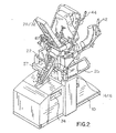
図1および図2を参照して、本発明が関する、患者の背の伸長、屈曲、牽引および伸延を達成するための本発明の脊柱指圧療法処置台は、脊柱指圧療法士、理学療法士、または物理療法医学に関与する他の健康の専門家の代表的な処置室の床12に静置するように適合された基部10を備えるように見え得る。脊柱指圧療法台は、この台の上で、種々の高さの患者の位置決めを可能にするために、必要に応じて一対の上昇手段14および16を備えるように見え得る。上昇手段14および16は、好ましくは、伸長可能な水圧ピストンを備え、この各々が、横軸22を支持する上側端を備える。
(Detailed description of the invention)
With reference to FIG. 1 and FIG. 2, the spinal pressure therapy treatment table of the present invention for achieving the patient's spinal extension, flexion, traction and distraction related to the present invention includes: Or it may appear to comprise a
図3において認められ得るように、軸22は、剛性上半身支持フレーム26のブロック支持体25のチャネル23内にジャーナルされる。
As can be seen in FIG. 3, the
これにより、固定多目的処置台は、上側部分28および下側部分30を有する上記上側支持フレーム26を備える。剛性支持フレーム26の上記下側部分30は、上記旋回ブロック25(図3を参照のこと)に固定され、このブロックは、フレーム26の下側部分30のほぼ中点で、上記旋回軸22上で回転可能である。さらに注意され得るように、上記上側部分28は、上側支持プラットフォーム26の上記下側部分30により規定される平面に関して、約30度の角度に方向付けられた平面を規定する。このような角度は、身体支持アセンブリ32(図1を参照のこと)により患者の上半身が人間工学的に支持されることを可能にし、背を凸状に延ばし、基部10に関して後方にすることを可能にする。支持アセンブリ32は、上記剛性支持プラットフォーム26の上記上側部分28の上に設置される。上記身体支持アセンブリは、分解されてもされなくてもよく、水圧ピストンもしくは空気圧ピストン、または身体支持アセンブリ32の上昇および下降のための他の手段を備える移動可能なセクションを備えていても備えていなくてもよい。
Accordingly, the fixed multipurpose treatment table includes the
図1および2を参照して、このシステムはまた、一対の位置調節可能な腕支持手段42および44を必要に応じて備えるように認められ得る、この腕支持手段は、身体支持アセンブリ32の側部の近くに位置付けられる。以下に示されるように、上記腕支持手段は、剛性支持プラットフォーム26の上記上側部分28に固定された、選択可能に調節可能な背面部分26を備える。上記腕支持手段42および44は、(i)実質的に水平なアームレスト50;(ii)上記アームレストから患者の方向に後ろ側に設置され、内向きの角度になっている、腰および肩の支持体51;ならびに(iii)上記腰および肩の支持体51の近くで、一体型に上向きかつ内向きに吊られている傾斜ハンドグリップ52を備える。
With reference to FIGS. 1 and 2, the system may also be recognized as optionally provided with a pair of positionable arm support means 42 and 44, which is located on the side of the
本発明の処置台は、腰および臀部の支持アセンブリ40をさらに備えるように認められ得る、この腰および臀部の支持アセンブリは、上記身体支持アセンブリ32から取り外される。腰アセンブリ40は、テレスコープ型ピストンロッド53および55(図3を参照のこと)またはその上昇および下降を提供する他の手段に接続される。上記アセンブリは、支持および組織の可動化を追加するために、膨張式の気泡の形態の内部エアクッションを備え得る。同じことが、上半身支持アセンブリについても言える。足および下腿アセンブリ制御バー209およびフットレスト20Aがまた、図1において認められ得る。
The treatment table of the present invention may be seen to further comprise a lumbar and buttocks support
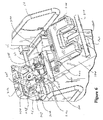
図3において、腰背中アセンブリ160および下腿/足支持アセンブリ200の全体図が示される。この図において、上記図面は、それぞれ、フレーム26に結合した上側部分28および下側部分30を備える下腿/足支持アセンブリおよび剛性支持フレーム26に関する腰背中支持アセンブリの全体的な位置を示す。また、図3において示されるのは、腰クッション40および腰クッション水圧/空気圧伸長ロッド53/55であり、このロッドは、水圧ピストン138/139と組み合わせて、剛性支持フレーム26の下側部分30に関する腰クッションの角度を決定する。上記シリンダ138/139は、剛性支持フレームプレート150上に静置され、これ自体は、剛性支持フレーム空間バー152、および主要軸22を通る主要水平軸チャネル23を備えるブロック支持体125によって支持されている(図1および2を参照のこと)。
In FIG. 3, a general view of the
図3においてさらに示されるのは、下腿/足支持リンクキャスティング(link casting)212、足チューブ214、フットレスト202および足首クッション204であり、これら全てが、下腿/足支持アセンブリ200のものである。また、アセンブリ200の側方回転機構290もこの図に示される。
Further shown in FIG. 3 is a leg / foot support link casting 212,
図4において、下腿/足支持アセンブリおよびその剛性フレーム26との関係性が、より詳細に示される。より具体的には、図4には、下腿/足支持アセンブリを垂直に位置決めする水圧208、ならびに、上記下腿/足支持リングキャスティング212および腰支持キャスティング112とのその関係性が示される。また、下腿/足支持リンクキャスティングのリンクキャスティング軸213、上記側方回転アセンブリ290、およびそこ横軸バー215、足チューブ214、側方足ブラケット274、足ロックハウジング264、フットレスト202、足首クッション204および下腿/足支持アセンブリ制御バー209が示される。また、矢印U、D、RおよびLがこの図において示され、これらは、下腿/足支持アセンブリ200の上下および左右の自由度を示す。
In FIG. 4, the crus / foot support assembly and its relationship with the
足支持アセンブリは、図5において、高くした位置で示される。この図において、垂直に位置決めする水圧ロッド208が、完全に縮まった位置で示され、この位置は、このアセンブリの垂直位置の上限に対応する。
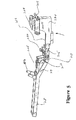
The foot support assembly is shown in an elevated position in FIG. In this figure, the vertically positioned
図6において、中央部分のカバーが取り外された、足および下腿アセンブリの全体図が示される。下腿/足支持アセンブリの下位アセンブリは、足チューブ214(また図5を参照のこと)に静置され、このチューブは、下腿/足支持リンクキャスティング212に旋回可能に装着されており、それ自体は、垂直に位置決めするために剛性支持フレーム(軸213を参照のこと)に旋回可能に装着されており、それによって、足/下腿支持アセンブリを、下側支持フレーム30の水平面の上30°まで、そして、その下15°まで、リフトアップすることを可能にすることに注意すべきである。
In FIG. 6, a general view of the foot and lower leg assembly is shown with the central cover removed. The lower assembly of the lower leg / foot support assembly rests in the foot tube 214 (see also FIG. 5), which is pivotally attached to the lower leg / foot support link casting 212, as such. Pivotally mounted on a rigid support frame (see axis 213) for vertical positioning, so that the foot / crus support assembly can be moved up to 30 ° above the horizontal plane of the
さらに図6において示されるのは、システムの側部ハンドル66であり、側方回転アセンブリ290に関して、横軸バー215、足支持アセンブリ200を足チューブ214に装着する垂直旋回軸294、ソレノイド298、およびソレノイドジャーナルプレート299が示される。従って、足支持アセンブリ制御バー209の制御303により、側方回転ソレノイド298が作動する際に、ジャーナルハウジングプレート299が、側方回転制御バー292上で左に回転し、それと共に下腿/足支持アセンブリ200が回転する。
Also shown in FIG. 6 is a
図7において、足側方ブラケット274を供えるアセンブリ200の下面図が示される。上記図面において、足機械式ロック266が、2つの機械式ロックブラケット268および269によって、足ロックハウジング264に固定されている。機械式ロックロッド220は、アセンブリ200の押出プレート226上にしっかりとねじ止めされている。機械式ロックソレノイド276が作動すると、上記機械式ロック266は、機械式ロックロッド220から開放され、足ロックハウジング264を、機械式ロックロッドに沿ってスライド可能にし、それによって、足/下腿支持アセンブリ200の全長を調節する。種々の身長の患者に適合するように、アセンブリを所定の位置に固定する前である。システムの動力足牽引操作の間に、水圧ロッド220、ばねアセンブリ224、押出プレート226および全ての足側方ブラケット群260(図11)が、一緒に移動する。
In FIG. 7, a bottom view of the
図8の分解図において、足側方ブラケット274および中央スライド228の前半分が認められ得る。この図において、水圧シリンダ218が、足チューブ214内に設置され、ここから、水圧ロッド220に電力供給される。水圧ロッドの他の端は、ばねアセンブリ224にしっかりと固定され、次いで、押出プレート226に設置される。上記プレートは、それ自体は、水圧/空気圧の線形牽引のために、中央スライド228に設置されている。中央スライド228は、外側スライド216の上をスライドする。
In the exploded view of FIG. 8, the front half of the
また、押出プレート226が、上記機械式ロックロッド220に装着されており、これは、足チューブ群210の残りと平行に延びる。足側方ブラケット群260の内側スライド270は、線形移動を可能にするために、上記中央スライド228内に挿入されている。そのハウジングを通して足側方ブラケット群260に固定されている機械式ロック266は、足側方ブラケット群260が、足チューブ群210に関して線形に移動するにつれ、機械式ロックロッド220に沿ってスライドする。足側方ブラケット群260のスライド移動は、患者の高さ調節のために使用される。
An
機械式ロック216が、機械式ロックロッド220に固定された後、上記足側方ブラケット群は、水圧ロッド221に関して固定され、次いでこれは、足側方ブラケット群260に線形牽引電力を提供するために使用され得る。このような電力牽引は、外側スライド216内に移動する上記中央スライド228によって、ならびに、足牽引シリンダである、水圧シリンダ218自体の作動によって、線形にガイドされる。
After the
図9において、特に、その足チューブ群210を備える足および下腿支持アセンブリ200の露出図(exposed view)が示される。足チューブ214は、その中に配置される水圧シリンダ218を露出するように認められ得る。さらに、足側方ブラケット274の1つが示される。さらに、水圧ロッド221は、押出プレート226に装着された、ショック吸収ばねアセンブリ224に接続され、次いで、これが、その各側の中央スライド228に設置されていることが認められ得る。内側スライド270は、足側方ブラケット274の内側に固定される。外側スライド216は、足チューブ214の側部に外部から装着される。中央スライド228および内側スライド270は、足ロック灰ジング内の機械式ロックによって間接的にロックされて、足側方ブラケットへの水圧電力の移動を保証する。図9においてまた、水圧シリンダ218の近位出口における過剰な圧力状態をモニターするロードセル219、および足チューブ214がその上で回転する、垂直軸294が示される。
In FIG. 9, in particular, an exposed view of the foot and lower
図10において、足/下腿支持リンクキャスティング212、垂直軸294、足チューブ214、横方向の側方回転バー215、玉軸受けスライドアセンブリ232、足ロックハウジング230、足側方ブラケット274、および押出プレート226を含む、足および下腿支持アセンブリ200の主要な構成要素が示される。この図において、足チューブ214は、足牽引水圧アセンブリ(図示せず)に適合し、足支持リンクキャスティング218の軸294上で水平方向に旋回する。足首クッション、足支持アセンブリ制御バー(図示せず)、および足首ハーネスが、足側方ブラケット上に設置され、玉軸受けスライドアセンブリ232によって、足チューブ214の上にスライド可能に設置されている。図7に示すように、機械式ロッキングアセンブリは、足ロックハウジング230の内側に設置され、患者の高さ調節が必要とされる場合に、足アセンブリの主要な構成要素をロック解除するように作動する。
In FIG. 10, foot / crus support link casting 212,
図11において、足チューブ群210および足側方ブラケット群260が示される。この図において、足ブラケット群は、垂直軸294によって足支持リンクキャスティング212に旋回可能に装着され、水圧シリンダ218、水圧ロッド220およびばねアセンブリ224を備える、足牽引水圧アセンブリを備える。
In FIG. 11, a
足側方ブラケット群260は、上記内側スライド270、中央スライド228および外側スライド216によって、足チューブ群210にスライド可能に装着される。患者の身長に適合するための個々の調節は、機械式ロック266を機械式ロックロッド222上をスライドさせ、こうして、足側方ブラケット群260の、足チューブ群210の水圧ロッド220に対する相対位置の調節の後に、機械式ロックロッドに足機械式ロックをロックすることによってなされる。
The foot
図6に関連する図12は、足/下腿支持アセンブリ200の側方回転運動および側方回転運動アセンブリ290の図である。この図面において、足支持アセンブリは、旋回軸294において、足/下腿支持リンクキャスティング212に旋回可能に装着されており、下腿および脚の側方(左右)の動きを達成する。側方回転機械式ロックアセンブリ(図6において上により完全に説明される)は、線形ロッド294を通って脚チューブ216に連結し、この線形ロッドは、側方回転アセンブリ290のジャーナルプレート299を、玉軸受けスライドアセンブリ232上に載っている横軸バー215に接続する(図10をまた参照のこと)。これにより、側方運動制御スイッチ303による側方回転ソレノイド298の作動は、足支持アセンブリの左右運動を支配する。一旦側方回転機械式ロック301によりロックされると、剛性フレーム30に対する足支持アセンブリ200の相対的な斜めの角度が維持される。
FIG. 12, related to FIG. 6, is an illustration of the lateral and lateral
図12においてまた、下腿/支持アセンブリ制御バー209に関連するコントロール、すなわち、電力牽引Y軸制御スイッチ300および302、ならびに、患者の高さ、Y軸調節スイッチ304が示される。図12においてまた、LCDリーダー207、フットレスト202、足首クッション204、および足首ストラップブラケット203が示される。
Also shown in FIG. 12 are the controls associated with the crus / support
図1および図2はさらに、医師による使用のためのシステム74を例示することが理解されるべきであり、このシステムは、以下の機能ボタンを備える:
1.TBL LFT=台を上昇。
2.TBL LWR=台を下降。
3.ROT BACK=台を後向きに回転。
4.ROT FWD=台を前向きに回転。
5.ARM UP=並進アームの高さを上昇。
6.ARM DWN=並進アームの高さを下降。
7.OPEN
8.OPEN
9.ARM R.UP=アームを回転しながら上昇。
10.ARM R.DOWN=アームを回転しながら下降。
11.LUM IN=腰を入れる(Lumber In)。
12.LUM OUT=腰を出す(Lumber Out)。
13.OPEN
14.OPEN
15.RBK TL=台を上昇しつつ、台を後向きに回転。
16.RFW TLW=台を下降しつつ、台を前向きに回転。
17.SAFETY ON AND OFF=空気圧/水圧ピストンを停止し、全ての台の動きを中止する、安全オンオフボタンが備え付けられる。
1 and 2 should further be understood to illustrate a
1. TBL LFT = Raise the stand.
2. TBL LWR = Descent the table.
3. ROT BACK = Turn the table backwards.
4). ROT FWD = Turn the table forward.
5. ARM UP = Increase translation arm height.
6). ARM DWN = Decrease translation arm height.
7). OPEN
8). OPEN
9. ARM R. UP = Ascending while rotating the arm.
10. ARM R. DOWN = Down while rotating the arm.
11. LUM IN = Lumbar In.
12 LUM OUT = Lumbar Out.
13. OPEN
14 OPEN
15. RBK TL = Ascending the table, rotating the table backwards.
16. RFW TLW = rotates the table forward while descending the table.
17. SAFETY ON AND OFF = A safety on / off button is provided that stops the pneumatic / hydraulic piston and stops all table motions.
安全性の指標として、他の機能の最適な患者の制御を有するコントロールがまた、オーバーヘッド把持手段54、またはハンドグリップ42(図1および2を参照のこと)に備え付けられ得る。 As an indicator of safety, a control with optimal patient control of other functions can also be provided in the overhead gripping means 54 or the handgrip 42 (see FIGS. 1 and 2).
本発明の好ましい実施形態が示され、説明されてきたが、本発明は、本明細書中に具体的に示され、説明されてきたもの以外を具体化し得ること、そして、上記実施形態の範囲内で、特定の変更が、本発明の根底にある概念または原理から逸脱することなく、形態および部品の配置においてなされ得ることが理解されるべきである。 While preferred embodiments of the invention have been shown and described, it will be appreciated that the invention may be embodied other than those specifically shown and described herein, and that the scope of the embodiments described above. It is to be understood that certain changes may be made in the form and arrangement of parts without departing from the concepts or principles underlying the invention.
Claims (3)
(a)床の上に載るように適合された基部;
(b)該基部と一体型に固定された上側端および下側端を有するシステム支持手段であって、その該上側端の近位にある旋回軸を備える、システム支持手段;
(c)上側端および下側端を有する選択可能に回帰伸長させるための手段であって、一方の端は、該システム支持手段に旋回可能に設置され、該選択可能な伸長手段は、該一方の端のその対向する端に関する回帰移動を提供する、手段;
(d)上側部分および下側部分を有する剛性支持プラットフォームであって、該プラットフォームは、該システム支持手段の該旋回軸に旋回可能に固定されており、さらに、該選択可能な伸長手段の該一方の端に旋回可能に固定されており、それにより、結果的に該支持プラットフォームの回転運動を提供する、剛性支持プラットフォーム;
(e)該剛性支持プラットフォームに関して調節可能に位置づけ可能な身体支持アセンブリであって、上側端および下側端を有する、身体支持アセンブリ;
(f)該身体支持アセンブリから枝分かれした腰支持アセンブリ;
(g)該身体支持アセンブリの近位部分に関して上または傾いた平面において、該腰アセンブリを独立して関節接合および移動するための手段;ならびに
(h)該剛性プラットフォーム上に横方向に設置された脚支持アセンブリであって、該アセンブリは、該プラットフォームに対して垂直な平面に関して位置調節可能であり、そして、該平面の下に延びる範囲を有し、その重心の下にある患者の下半身の湾曲がそれにより調節され得る、クッションを備える、脚支持アセンブリ
を備え、これにより、患者の該背に対する種々の治療効果が、地面からの力学的回転、該基部に関する該身体プラットフォームの選択可能な位置調節、ならびに、患者の重心に関する該背中アセンブリおよび該脚支持アセンブリのいずれかまたは両方の位置の変化を通じて達成され得る、台。 A platform for supporting and treating the legs and lower legs for extending, flexing, traction, distraction and lateral movement of the patient's back and lower body, the platform being:
(A) a base adapted to rest on the floor;
(B) system support means having an upper end and a lower end fixed integrally with the base, the system support means comprising a pivot axis proximal to the upper end;
(C) means for selectably regressive extension having an upper end and a lower end, wherein one end is pivotally mounted to the system support means, the selectable extension means comprising the one Means for providing a reciprocal movement with respect to its opposite end of the end of the
(D) a rigid support platform having an upper portion and a lower portion, wherein the platform is pivotally secured to the pivot axis of the system support means, and the one of the selectable extension means A rigid support platform that is pivotally secured to the ends of the support, thereby providing rotational movement of the support platform;
(E) a body support assembly adjustably positionable with respect to the rigid support platform, the body support assembly having an upper end and a lower end;
(F) a waist support assembly branched from the body support assembly;
(G) means for independently articulating and moving the waist assembly in a plane up or inclined with respect to a proximal portion of the body support assembly; and (h) installed laterally on the rigid platform; A leg support assembly that is adjustable with respect to a plane perpendicular to the platform and that has a range extending below the plane and is below the center of gravity of the patient's lower body curvature Comprising a leg support assembly with a cushion, whereby various therapeutic effects on the back of the patient can be adjusted by mechanical rotation from the ground, selectable position adjustment of the body platform relative to the base And a change in the position of either or both of the back assembly and the leg support assembly with respect to the patient's center of gravity Can be achieved through the pedestal.
(j)前記身体支持プラットフォームの長手軸に関する前記脚支持アセンブリの側方の移動を可能にするための手段
を備える、請求項1に記載の台。 In addition:
The platform of claim 1, comprising (j) means for allowing lateral movement of the leg support assembly relative to a longitudinal axis of the body support platform.
前記身体支持アセンブリの回転移動の間に、前記患者を該身体支持アセンブリに留まらせることを可能にするための手段
を備える、請求項2に記載の台。 In addition:
The platform of claim 2, comprising means for allowing the patient to remain on the body support assembly during a rotational movement of the body support assembly.
Applications Claiming Priority (2)
| Application Number | Priority Date | Filing Date | Title |
|---|---|---|---|
| US10/413,730 US6923825B2 (en) | 2000-09-13 | 2003-04-15 | Calf and foot support and adjustment assembly |
| PCT/US2004/011433 WO2004091467A2 (en) | 2003-04-15 | 2004-04-14 | Calf and foot support and adjustment assembly |
Publications (2)
| Publication Number | Publication Date |
|---|---|
| JP2006523512A true JP2006523512A (en) | 2006-10-19 |
| JP2006523512A5 JP2006523512A5 (en) | 2007-06-28 |
Family
ID=33298375
Family Applications (1)
| Application Number | Title | Priority Date | Filing Date |
|---|---|---|---|
| JP2006510007A Pending JP2006523512A (en) | 2003-04-15 | 2004-04-14 | Assembly for supporting and adjusting the lower leg and foot |
Country Status (6)
| Country | Link |
|---|---|
| US (2) | US6923825B2 (en) |
| EP (1) | EP1617794B1 (en) |
| JP (1) | JP2006523512A (en) |
| KR (1) | KR100979585B1 (en) |
| CA (1) | CA2520953C (en) |
| WO (1) | WO2004091467A2 (en) |
Families Citing this family (18)
| Publication number | Priority date | Publication date | Assignee | Title |
|---|---|---|---|---|
| US6923825B2 (en) * | 2000-09-13 | 2005-08-02 | David F. Cuccia | Calf and foot support and adjustment assembly |
| US20080167684A1 (en) * | 2003-04-15 | 2008-07-10 | Cuccia David F | Treatment table with calf/foot assembly and method of use |
| US7951097B2 (en) * | 2009-06-15 | 2011-05-31 | Schaeffer Dwight L | Automated therapy table for treating lower extremities and method therefor |
| KR101054232B1 (en) * | 2009-12-24 | 2011-08-08 | 한국산재의료원 | Magnetic Fluid Control Spinal Bending Exercise Trainer |
| WO2011119902A1 (en) * | 2010-03-25 | 2011-09-29 | Randall Fenkell | Continuous passive motion device |
| KR101415104B1 (en) | 2012-03-05 | 2014-07-04 | 주식회사 씨에스테크놀로지 | Table for physiotherapy |
| CN104027161A (en) * | 2014-04-30 | 2014-09-10 | 陈春美 | Multi-direction adjustable extracorporeal restoration iliolumbar cushion |
| KR101706586B1 (en) * | 2014-12-04 | 2017-02-27 | 허강수 | Spondylopathy treatment apparatus using three-level spine tetracting technjque , method, recording medium |
| KR101706587B1 (en) * | 2014-12-04 | 2017-02-15 | 허강수 | Spine retracting apparatus using sequential three-level spine retracting technique, method, recording medium |
| US9616284B1 (en) * | 2016-08-25 | 2017-04-11 | Aganyan Inc. | Portable multi-functional upright body stretching apparatus |
| US9764188B1 (en) * | 2016-08-25 | 2017-09-19 | Aganyan Inc. | Portable multi-functional upright body stretching apparatus |
| CN107693182B (en) * | 2016-10-14 | 2018-08-24 | 崔韡 | A kind of wearable draft gear of nursing |
| CN109172240B (en) * | 2018-09-03 | 2020-11-17 | 张敏丽 | Supporting device for leg nursing |
| CN109620506B (en) * | 2019-01-24 | 2024-04-09 | 河北医科大学第三医院 | Lumbar disc herniation traction frame |
| CN111388253A (en) * | 2020-03-26 | 2020-07-10 | 河北地质大学华信学院 | Movable gynaecology and obstetrics medical vehicle |
| CN111904772A (en) * | 2020-08-06 | 2020-11-10 | 张雷 | Multi-section double-chain-disc folding type traction leg rod mechanism of orthopedic traction frame |
| CN112972192B (en) * | 2021-03-02 | 2022-12-06 | 新疆维吾尔自治区人民医院 | Auxiliary appliance for lower limb rehabilitation |
| CN115517875A (en) * | 2022-04-13 | 2022-12-27 | 崔水娟 | Pediatric leg fracture postoperative care bed |
Citations (5)
| Publication number | Priority date | Publication date | Assignee | Title |
|---|---|---|---|---|
| US3060926A (en) * | 1961-02-06 | 1962-10-30 | William E Westcott | Therapeutic table |
| US3238936A (en) * | 1962-04-16 | 1966-03-08 | Nat Foundation For Physical Me | Apparatus for mechanical corrective therapy |
| US4582311A (en) * | 1983-10-27 | 1986-04-15 | Steffensmeier Lloyd A | Hydraulically controlled chiropractic table |
| JPH0339967U (en) * | 1989-08-28 | 1991-04-17 | ||
| JP2000237222A (en) * | 1999-02-23 | 2000-09-05 | Koremori Kawai | Lumbago treating apparatus |
Family Cites Families (9)
| Publication number | Priority date | Publication date | Assignee | Title |
|---|---|---|---|---|
| US2023429A (en) * | 1934-05-21 | 1935-12-10 | Williams Mfg Company Inc | Chiropractic table |
| US2273088A (en) | 1940-01-03 | 1942-02-17 | Byers George | Massaging table |
| US2267054A (en) * | 1940-10-17 | 1941-12-23 | Williams Mfg Company | Chiropractic table |
| US5176706A (en) * | 1991-09-06 | 1993-01-05 | Lee Jong W | Spinal curvature correction device |
| US5794286A (en) * | 1995-09-13 | 1998-08-18 | Standex International | Patient treatment apparatus |
| US5860899A (en) * | 1996-10-07 | 1999-01-19 | New Back Technologies, L.L.C. | Back manipulating apparatus |
| US5840001A (en) * | 1997-03-24 | 1998-11-24 | Schedel; Robert M. | Therapy exercise table |
| US6547809B1 (en) * | 1999-09-14 | 2003-04-15 | David F. Cuccia | Multi-function chiropractic treatment table |
| US6923825B2 (en) * | 2000-09-13 | 2005-08-02 | David F. Cuccia | Calf and foot support and adjustment assembly |
-
2003
- 2003-04-15 US US10/413,730 patent/US6923825B2/en not_active Expired - Fee Related
-
2004
- 2004-04-14 WO PCT/US2004/011433 patent/WO2004091467A2/en active Application Filing
- 2004-04-14 KR KR1020057019314A patent/KR100979585B1/en not_active IP Right Cessation
- 2004-04-14 JP JP2006510007A patent/JP2006523512A/en active Pending
- 2004-04-14 CA CA002520953A patent/CA2520953C/en not_active Expired - Fee Related
- 2004-04-14 EP EP04759515A patent/EP1617794B1/en not_active Expired - Lifetime
-
2005
- 2005-07-25 US US11/189,956 patent/US7309347B2/en not_active Expired - Fee Related
Patent Citations (5)
| Publication number | Priority date | Publication date | Assignee | Title |
|---|---|---|---|---|
| US3060926A (en) * | 1961-02-06 | 1962-10-30 | William E Westcott | Therapeutic table |
| US3238936A (en) * | 1962-04-16 | 1966-03-08 | Nat Foundation For Physical Me | Apparatus for mechanical corrective therapy |
| US4582311A (en) * | 1983-10-27 | 1986-04-15 | Steffensmeier Lloyd A | Hydraulically controlled chiropractic table |
| JPH0339967U (en) * | 1989-08-28 | 1991-04-17 | ||
| JP2000237222A (en) * | 1999-02-23 | 2000-09-05 | Koremori Kawai | Lumbago treating apparatus |
Also Published As
| Publication number | Publication date |
|---|---|
| KR20060023523A (en) | 2006-03-14 |
| EP1617794A2 (en) | 2006-01-25 |
| EP1617794A4 (en) | 2007-10-24 |
| CA2520953C (en) | 2009-12-22 |
| KR100979585B1 (en) | 2010-09-01 |
| US20050256538A1 (en) | 2005-11-17 |
| US6923825B2 (en) | 2005-08-02 |
| EP1617794B1 (en) | 2012-09-12 |
| CA2520953A1 (en) | 2004-10-28 |
| US20030216782A1 (en) | 2003-11-20 |
| WO2004091467A3 (en) | 2005-06-30 |
| US7309347B2 (en) | 2007-12-18 |
| WO2004091467A2 (en) | 2004-10-28 |
Similar Documents
| Publication | Publication Date | Title |
|---|---|---|
| US7309347B2 (en) | Foot and calf support and adjustment assembly | |
| US4915101A (en) | Rotatable treatment table having adjustable support assemblies | |
| US6547809B1 (en) | Multi-function chiropractic treatment table | |
| US6558304B1 (en) | Apparatus for restoring the balance of the human body | |
| JP2006523512A5 (en) | ||
| US4531514A (en) | Orthopedic traction apparatus | |
| US6905508B2 (en) | Lumbar support and adjustment assembly | |
| US4419989A (en) | Tiltable reclining and seating device | |
| AU2006316430B2 (en) | Spinal therapy apparatus | |
| US5922011A (en) | Multi-function chiropractic treatment table | |
| US20080167684A1 (en) | Treatment table with calf/foot assembly and method of use | |
| JP2010264287A (en) | Device for preventing or relieving pain in lower back | |
| US3904195A (en) | Body exercising and re-education apparatus | |
| EP0131167A2 (en) | Therapeutic device for body stretching | |
| WO2007027573A2 (en) | Lumbar lordosis brace | |
| KR20090055662A (en) | Spinal correction equipment using one's own weight | |
| US5002043A (en) | Inversion apparatus | |
| KR102278217B1 (en) | Disc Therapy Apparatus | |
| US20030126686A1 (en) | Intercourse aiding apparatus | |
| CA2374259C (en) | Multi-function chiropractic treatment table | |
| KR101345822B1 (en) | Vertebra proofreading device | |
| CA1310026C (en) | Inversion apparatus | |
| US20180214335A1 (en) | Upright spine decompression method by gravity DeCOMPRESSit | |
| WO2014080434A1 (en) | An apparatus for the treatment of osteopathic lesions of the pelvis | |
| WO1997039783A2 (en) | A table for backbone setting |
Legal Events
| Date | Code | Title | Description |
|---|---|---|---|
| A524 | Written submission of copy of amendment under article 19 pct |
Free format text: JAPANESE INTERMEDIATE CODE: A524 Effective date: 20070411 |
|
| A621 | Written request for application examination |
Free format text: JAPANESE INTERMEDIATE CODE: A621 Effective date: 20070411 |
|
| A521 | Request for written amendment filed |
Free format text: JAPANESE INTERMEDIATE CODE: A523 Effective date: 20070511 |
|
| A131 | Notification of reasons for refusal |
Free format text: JAPANESE INTERMEDIATE CODE: A131 Effective date: 20100126 |
|
| A601 | Written request for extension of time |
Free format text: JAPANESE INTERMEDIATE CODE: A601 Effective date: 20100426 |
|
| A602 | Written permission of extension of time |
Free format text: JAPANESE INTERMEDIATE CODE: A602 Effective date: 20100507 |
|
| A02 | Decision of refusal |
Free format text: JAPANESE INTERMEDIATE CODE: A02 Effective date: 20100714 |