JP2006520502A - Batch-based methods and means for graphical manipulation of workflows - Google Patents
Batch-based methods and means for graphical manipulation of workflows Download PDFInfo
- Publication number
- JP2006520502A JP2006520502A JP2006507157A JP2006507157A JP2006520502A JP 2006520502 A JP2006520502 A JP 2006520502A JP 2006507157 A JP2006507157 A JP 2006507157A JP 2006507157 A JP2006507157 A JP 2006507157A JP 2006520502 A JP2006520502 A JP 2006520502A
- Authority
- JP
- Japan
- Prior art keywords
- hierarchical
- nodes
- node
- edge
- primitive
- Prior art date
- Legal status (The legal status is an assumption and is not a legal conclusion. Google has not performed a legal analysis and makes no representation as to the accuracy of the status listed.)
- Pending
Links
Images


Classifications
-
- G—PHYSICS
- G06—COMPUTING; CALCULATING OR COUNTING
- G06Q—INFORMATION AND COMMUNICATION TECHNOLOGY [ICT] SPECIALLY ADAPTED FOR ADMINISTRATIVE, COMMERCIAL, FINANCIAL, MANAGERIAL OR SUPERVISORY PURPOSES; SYSTEMS OR METHODS SPECIALLY ADAPTED FOR ADMINISTRATIVE, COMMERCIAL, FINANCIAL, MANAGERIAL OR SUPERVISORY PURPOSES, NOT OTHERWISE PROVIDED FOR
- G06Q10/00—Administration; Management
- G06Q10/06—Resources, workflows, human or project management; Enterprise or organisation planning; Enterprise or organisation modelling
Abstract
本発明は、製造および、研究や開発におけるワークフローに関し、特に、製造活動とともに、研究や開発の遂行やそれらの記録を自動化する手段に関する。ここに、適応階層型ワークフロー環境における、バッチベースの作業手順を確定・実行する手段を説明する。オートフィルアルゴリズムは、適応階層型ワークフロー環境におけるバッチベースの作業手順を定義して自動実行する手段を提供し、実験手順計画、実行、記録、およびロボット機器の駆動を含む広範囲の適用に好適である。The present invention relates to manufacturing and workflows in research and development, and more particularly to means for automating research and development performance and recording thereof together with manufacturing activities. Here, means for determining and executing a batch-based work procedure in the adaptive hierarchical workflow environment will be described. The autofill algorithm provides a means for defining and automatically executing batch-based work procedures in an adaptive hierarchical workflow environment and is suitable for a wide range of applications including experimental procedure planning, execution, recording, and driving robotic equipment.
Description
(発明の背景)
(発明の分野)
本発明は、製造および、研究や開発におけるワークフローに関し、特に、製造活動とともに、研究や開発の遂行やそれらの記録を自動化する手段に関する。
(Background of the Invention)
(Field of Invention)
The present invention relates to manufacturing and workflows in research and development, and more particularly to means for automating research and development performance and recording thereof together with manufacturing activities.
(関連分野の説明)
多くの研究者が、研究・開発の遂行および/もしくは記録に際し、自動数式処理システムに加えて、所在地がワシントンのレッドモンドとする、マイクロソフト株式会社が提供するExcel(登録商標)などの、実験ノートや自動表計算を使用している。
(Description of related fields)
Many researchers use experimental formulas, such as Excel (registered trademark) provided by Microsoft Corporation, in addition to an automatic mathematical expression processing system, in addition to an automatic mathematical expression processing system, when conducting research and development and / or recording. And using automatic spreadsheets.
実験手順の設計においては、バッチに基づく規則性を利用する必要がある。設計者は個々のオペレーションの代わりに、オペレーションのバッチを用いて作業手順を作成することが求められ、そうすることで、有用かつ精細な構造が存在することを容易に示すことができる。バッチベースの作業手順の設計において重要な点は、ユーザーが作成したバッチベースの作業手順から精細なトポロジーを導くために簡単なルールを設けることである。そのルール、もしくはアルゴリズムは、ユーザーによる理解・予想が可能なものであり、同時に、ユーザーが、多岐にわたる有益かつ精細なトポロジーを作成する能力を提供するものであることが期待される。 In designing experimental procedures, it is necessary to use batch-based regularity. Designers are required to create work procedures using batches of operations instead of individual operations, which makes it easy to show that a useful and fine structure exists. An important point in designing a batch-based work procedure is to provide simple rules to derive a fine topology from a user-created batch-based work procedure. The rules or algorithms can be understood and predicted by the user, and at the same time, the user is expected to provide the ability to create a wide variety of useful and detailed topologies.
(発明の概要)
ここに、適応階層型ワークフロー環境における、バッチベースの作業手順を確定・実行する手段を説明する。そういった手段は、ロボット操作機器の駆動に加えて、実験手順計画、実行、記録を含む様々な用途に適している。
(Summary of Invention)
Here, means for determining and executing a batch-based work procedure in the adaptive hierarchical workflow environment will be described. Such means are suitable for various applications including experimental procedure planning, execution, and recording in addition to driving robot operating devices.
以下の図面において、同一の符号は同様の構成要素もしくは作用を指す。図面中の構成要素の大きさおよび相対位置は必ずしも図面のそれに従うものではなく、例えば、各構成要素の形状や角度は図面のそれに従うものではなく、いくつかの構成要素は、図面を見やすくする目的で、任意に拡大、配置される。さらに、それぞれの構成要素の特有の形状は、特定の構成要素における実際の形状を伝えることを意図したものではなく、単に、図面において認識しやすいように選択されたものである。 In the following drawings, the same reference numeral indicates the same component or action. The sizes and relative positions of the components in the drawings do not necessarily follow those in the drawings, for example, the shape and angle of each component do not follow those in the drawings, and some components make the drawings easier to read. It is arbitrarily enlarged and arranged for the purpose. Further, the specific shape of each component is not intended to convey the actual shape of a particular component, but is simply selected for easy recognition in the drawings.
(発明の詳細な説明)
以下の説明においては、特定の詳細事項の説明を行うことで、本発明の各実施形態への十分な理解を促しているが、当業者であれば、これらの詳細な情報がなくとも本発明を実施可能であることは理解できるであろう。その他の例においては、本発明の実施形態に対する説明を不必要に曖昧にすることがないように、バッチベース作業設計に関連する公知の構造の図示もしくは説明は行わない。
(Detailed description of the invention)
In the following description, specific details are described to promote a sufficient understanding of the embodiments of the present invention. However, those skilled in the art will be able to understand the present invention without these detailed information. It will be understood that can be implemented. In other instances, well-known structures associated with batch-based work design are not shown or described in order not to unnecessarily obscure the description of the embodiments of the invention.
内容が別の意味を必要としない限り、本明細書および添付の請求項において、「備える」および「備えて」などの単語は、「含むが、それに限定はされない」という意味での非限定的かつ包含的な解釈をなされるべきものある。 Unless the context requires another meaning, in this specification and the appended claims, words such as “comprising” and “comprising” are non-limiting in the sense of “including but not limited to” And there should be an inclusive interpretation.
本明細書を通して、「一つの実施形態もしくは実施形態」という記載は、その実施形態に関連して説明される特定の機能、構造もしくは特徴が、少なくとも本発明の一つの実施形態に含まれるという意味である。このように、本明細書を通して各所に記載される「一つの実施形態において」もしくは「実施形態において」という表現は、必ずしもすべてが同じ実施形態に言及しているとは限らない。さらに、特定の機能、構造もしくは特徴は、一つ以上の実施形態において好適に組み合わせてもよい。 Throughout this specification, reference to “an embodiment or embodiment” means that a particular function, structure, or feature described in connection with that embodiment is included in at least one embodiment of the invention. It is. Thus, the phrases “in one embodiment” or “in an embodiment” described throughout the specification are not necessarily all referring to the same embodiment. Furthermore, the particular functions, structures or features may be suitably combined in one or more embodiments.
本明細書に記載される各見出しは便宜上のものであり、請求発明の範囲もしくは意義に解釈が加えられるものではない。 Each heading described herein is for convenience only and does not add any interpretation to the scope or meaning of the claimed invention.
図1Aおよび以下の論考は、本発明が実施される、好適なコンピューター環境に対する簡略かつ概要説明である。指定はないが、本発明における実施形態は、パソコンによって実行されるプログラムアプリケーションモジュール、目的もしくはマクロなどの、コンピューターにより実行可能な指示を一般的な背景として説明される。関連分野の当業者であれば、本発明が、携帯用機器、マイクロプロセッサシステム、マイクロプロセッサを用いたもしくはプログラミング可能な消費電子製品、ネットワークパソコン、ミニコン、メインフレームコンピューターなどを含む、他のコンピューターシステム構成を用いて実施可能であることを認識するであろう。本発明は、コミュニケーションネットワークを介して連結された遠隔処理装置によってタスクやモジュールが行われる、分散型コンピューター環境において実施可能である。ある分散型コンピューター環境では、プログラムモジュールはローカルおよび遠隔のメモリ記憶装置の両方に配置される。 FIG. 1A and the following discussion is a brief and general description of a preferred computing environment in which the present invention is implemented. Although not specified, the embodiments of the present invention are described with general background of instructions executable by a computer, such as program application modules, objects or macros executed by a personal computer. One of ordinary skill in the relevant art will recognize that the present invention includes other computer systems, including portable devices, microprocessor systems, consumer electronic products using or programmable to microprocessors, network personal computers, minicomputers, mainframe computers, and the like. It will be appreciated that the configuration can be implemented. The present invention can be practiced in a distributed computing environment where tasks and modules are performed by remote processing devices that are linked through a communications network. In some distributed computing environments, program modules are located in both local and remote memory storage devices.
図1Aを参照して、本発明で言及される従来のパソコンである、コンピューターシステム10は、処理部12と、システムメモリ14と、前記システムメモリ14の処理部12への連結を含む、様々なシステム構成要素を連結するシステムバス16を備える。処理部12は論理処理部であればどれでもよく、例としては、一つ以上の中央処理器(CPUs)、デジタル信号処理器(DSPs)、アプリケーション用集積回路(ASIC)などである。別の説明がない限りは、図1Aに図示する様々なブロックの構成および作用は、従来の設計によるものである。よって、関連分野の当業者であれば理解できるものとして、それらのブロックは本明細書における詳細説明は省略する。
Referring to FIG. 1A, a
システムバス16は、メモリ制御器に搭載されるメモリバス、周辺バス、および/もしくはローカルバスを含む、公知のバスの構造もしくは構成あれば、すべて用いることができる。システムメモリ14は、読み取り専用メモリ(「ROM」)18およびランダムアクセスメモリ(「RAM」)20を含む。前記ROM18の一部を構成する基本入力/出力システム(「BIOS」)22は、スタートアップ中などに、コンピューターシステム10内のエレメント間の情報転送をサポートする基本ルーティンを含有する。
The
コンピューターシステム10はまた、ハードディスク25に対する読み取りおよび書き込み用のハードディスクドライブ24などの、一つ以上の回転メディアメモリと、それぞれ、取り外し可能な光ディスク30と磁気ディスク32に対する読み取りと書き込みを行う光ディスクドライブ26と磁気ディスクドライブ28を含む。光ディスク30は、CD−ROMを採用してもよく、一方、磁気ディスク32は磁気フロッピー(登録商標)ディスクもしくはディスケットを採用できる。ハードディスクドライブ24、光ディスクドライブ26、磁気ディスクドライブ28は、バス16を介して処理部12と交信する。ハードディスクドライブ24、光ディスクドライブ26、磁気ディスクドライブ28は、関連分野の当業者に公知のように、それらのドライブとバス16間に連結されるインターフェースもしくはコントローラーを、例えば、IDE(すなわち、Integrated Drive Electronics)インターフェースを介して含んでもよい。ドライブ24,26,28とそれに関連したコンピューターで読み取り可能な媒体は、コンピューターシステム10に対して、コンピューターで読み取り可能な指示、データ構造、プログラムモジュール、およびその他のデータの不揮発性記憶部を提供する。上記に説明したコンピューターシステム10はハードディスク25、光ディスク30、磁気ディスク32を採用しているが、関連分野の当業者であれば、デジタルビデオディスク(「DVD」)、ベルヌーイカートリッジなどの、他のタイプの回転メディアメモリ、コンピューターで読み取り可能な媒体が採用可能であることを認識するであろう。関連分野の当業者はまた、例えば、磁気カセット、フラッシュメモリカード、RAMs、ROMs、スマートカードなどの非回転メディアメモリを例とした、コンピューターがアクセス可能なデータを保存できる他のタイプのコンピューター読み取り可能媒体が採用可能であることを認識するであろう。
The
オペレーティングシステム34、一つ以上のアプリケーションプログラム36、他のプログラムもしくはモジュール38、プログラムデータ40などのプログラムモジュールはシステムメモリ14に格納される。システムメモリ14はまた、コンピューターシステム10に、サーバーコンピュータ上の他のサーバーアプリケーションとともに、インターネット、企業のイントラネット、もしくは他のネットワークのホームページなどのソースに対する、データのアクセスおよび交換を許可するブラウザー41を含む。前記ブラウザー41は、ハイパーテキストマークアップ言語などのマークアップ言語(「HTML」)を用いており、情報文書のデータにその文書構造を表すために付加された構文上の区切り文字を使用するマークアップ言語を用いて作動する。
Program modules such as operating system 34, one or
図1Aの図示ではシステムメモリに格納されているが、オペレーティングシステム34、アプリケーションプログラム36、その他のプログラムモジュール38、プログラムデータ40、ブラウザー41はハードディスクドライブ24のハードディスク25、光デスクドライブ26の光ディスク30、および/もしくは磁気ディスクドライブ28の磁気ディスク32に格納することができる。ユーザーは、キーボード42やマウス44などのポインター器などの入力機器を使って、コンピューターシステム10にコマンドや情報を入力できる。他の入力機器としては、マイクロフォン、ジョイスティック、ゲームパッド、スキャナーなどが含まれる。これらとそれ以外の入力機器は、バス16を連結するシリアルポートインターフェースなどのインターフェース46を介して処理部12に接続されるが、パラレルポート、ゲームポート、ユニバーサルシリアルバス(「USB」)などの、他のインターフェースも使用可能である。モニター48もしくは他のディスプレイ機器は、ビデオアダプターなどのビデオインターフェース50を介して、バス16に連結されてもよい。コンピューターシステム10は、スピーカー、プリンターなどの、他の出力機器を含むこともできる。
Although stored in the system memory in the illustration of FIG. 1A, the operating system 34,
コンピューターシステム10は、一つ以上のリモートコンピューター、もしくはマイクロ流体システム60などのロボットシステムへの論理接続を用いてネットワーク化された環境での動作が可能である。コンピューターシステム10は、公知の通信手段であればどれでも採用可能であり、例えば、ローカルエリアネットワーク(「LAN」)52、ワイドエリアネットワーク(「WAN」)、もしくはインターネット54である。上記のようなネットワーク環境は、企業規模でのコンピューターシステム、イントラネット、およびインターネットにおいて周知である。
The
LANのネットワーク環境で使用される場合、コンピューターシステム10は、アダプターもしくはネットワークインターフェース56を介してLAN52に接続される(通信可能にバス16に接続される)。WANのネットワーク環境で使用される場合、コンピューターシステム10は、モデム57、もしくはWAN/インターネット54上で通信を確立する他の機器を含むことが多い。モデム57は、通信を可能にするようにインターフェース46とWAN/インターネット54間に接続される形で、図1Aに図示されている。ネットワーク化された環境では、プログラムモジュール、アプリケーションプログラム、もしくはデータ、もしくはそれらの一部が、サーバーコンピューター(図示なし)に格納される。関連分野の当業者であればただちに認識するであろうが、図1Aに図示のネットワーク接続がコンピューター間、および/もしくはロボットシステム60間の通信網を確立する数例にすぎず、例えば、ワイヤレス接続を含む他の接続方法を用いることもできる。
When used in a LAN network environment, the
コンピューターシステム10は、スロット58などの一つ以上のインターフェースを含むことで、コンピューターシステム10に対して、内臓もしくは外付けのどちらかの形態での機器の追加を可能にしてもよい。例えば、好適なインターフェースとしては、オプションカード、シリアおよび/もしくはパラレルポート、USBポート(すなわち、ユニバーサルシリアルバス)、オーディオ入力/ 出力(すなわち、I/O)、および、MIDI/ジョイスティック コネクター、および/もしくはメモリ用スロット用のISA(業界標準アーキテクチャ)、IDE、PCI(すなわち、パソコンインターフェース)、および/もしくは、AGP(すなわち、アドバンスグラフィックプロセッサー)のスロットコネクター、MIDI/ジョイステックコネクター、および/もしくはメモリ用スロットを含んでもよい。
本明細書で記載されている「コンピューターで読み取り可能な媒体」という表現は、処理部12に実行を促す指示を送る際に関与する媒体であればいかなるものも指す。上記媒体は様々な形態をとり、不揮発性媒体、揮発性媒体、および伝送媒体を含むが、それらに限定されるものではない。不揮発性媒体の例としては、ハードディスク25、光ディスク30、もしくは磁気ディスク32のそれぞれを含む。揮発性媒体は、システムメモリ14などのダイナミックメモリを含む。伝送媒体は、同軸ケーブル、銅線、および光ファイバーを含み、システムバス16を備えるワイヤーを含む。伝送媒体はまた、電波や赤外線データ通信中に生成されるものなど、音波や光波の形態を適用可能である。
The expression “computer-readable medium” described in this specification refers to any medium that is involved in sending an instruction to the
コンピューターで読み取り可能な媒体の一般形態としては、例えば、フロッピー(登録商標)ディスク、フレキシブルディスク、ハードディスク、磁気テープもしくはそれ以外の磁気媒体、CD−ROM、それ以外の光媒体、パンチカード、ペーパーテープ、それ以外のホールパターンを設けた物理的媒体、RAM、PROM、EPROM、フラッシューEPROM、それ以外のメモリチップもしくはカートリッジ、以降に説明する搬送波、それ以外のコンピューターが読み取り可能であるすべての媒体を含む。 General forms of computer-readable media include, for example, floppy (registered trademark) disks, flexible disks, hard disks, magnetic tapes or other magnetic media, CD-ROMs, other optical media, punch cards, and paper tapes. , Physical media with other hole patterns, RAM, PROM, EPROM, flash-EPROM, other memory chips or cartridges, carrier waves described below, and all other media that can be read by computers Including.
上記様々な態様のコンピューターで読み取り可能な媒体は、一つ以上の指示の一つ以上のシークエンス、を実行に際して処理部12に送る作業に関与してもよい。例えば、各指示は当初、リモートコンピューターの磁気ディスクに載せて移送されてもよい。リモートコンピューターは、そのダイナミックなメモリに指示を搭載し、その指示を、モデムを用いて電話線にのせて伝送することができる。コンピューターシステム10用のモデム57は、電話線を通じてデータを受け取り、そのデータを、赤外線トランスミッターを用いて赤外線信号に変換することができる。システムバス16に連結された赤外線検知器は、赤外線信号で運ばれたデータを受け取り、そのデータをシステムバス16に配置する。システムバス16は、そのデータをシステムメモリ14に送り、そこから、処理部12が指示を取り出して実行する。システムメモリ14が受け取った指示は、処理部12による実行の前か後かどちらかに任意に、記憶器に格納される。
The computer-readable medium of the various aspects described above may be involved in the work of sending one or more sequences of one or more instructions to the
(問題点の事例)
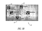
図1Bは、生物学の実験室において、人間かロボット機器によって行われる一組のタスクの簡単な階層型ワークフロー図62を示す。このワークフロー図62は、「Workflow 63」と名づけられたノードが、それ以外の、「サンプル64」、「Reagent 65」、「Dispense 66」、および「Combine 67」と名づけられた4つのノードを含有するために、階層型となっている。細い矢印68はコンテナシップを表し、太い矢印69はワークフローのシークエンスを表す。
(Examples of problems)
FIG. 1B shows a simple hierarchical workflow diagram 62 of a set of tasks performed by a human or robotic instrument in a biology laboratory. In this workflow diagram 62, the node named “Workflow 63” contains the other four nodes named “
この例では、ワークフロー63の最終目的は、生物学的サンプルを何らかのリージェントとコンバインし、5百万セルのカウントにおいて、希望するボリュームである50mLを生成することである。さらに重要なのは、サンプルとリージェントの必要とされるボリュームは、オリジナルサンプルのセルの数とボリューム(セル密度)に基づいてコンピューター計算が必要なことである。例えば、必要されるオリジナルサンプルのボリュームは、サンプルの総カウントに対する希望カウント(5M)の割合をサンプルボリュームで乗算したものである(ボリューム*総/希望)。この量は、希望ボリューム(50mL)から減算されて、どれくらいのリージェントが必要かを決定する。これらの数式は、表計算で使用されるタイプのものに非常に似通っているが、残念な点は、フローグラフの自由な形式では、コラムとローの配置を、変数を参照する手段としては使えないことである。 In this example, the ultimate goal of workflow 63 is to combine the biological sample with some regent to produce a desired volume of 50 mL at a 5 million cell count. More importantly, the volume required for the sample and the regent requires a computer calculation based on the number and volume (cell density) of the original sample cells. For example, the volume of the original sample required is the ratio of the desired count (5M) to the total sample count multiplied by the sample volume (volume * total / desired). This amount is subtracted from the desired volume (50 mL) to determine how much regent is needed. These formulas are very similar to the types used in spreadsheets, but unfortunately, in the free form of the flow graph, column and row arrangements can be used as a means of referencing variables. It is not.
本明細書では、ユーザーが、ノードやプロパティ名の点で簡単な条件式を生成できるような、階層型ネーミングとルックアップアルゴリズムが開示される。詳細に説明すると、上記各数式はこの方法を用いると以下になる。 This specification discloses a hierarchical naming and lookup algorithm that allows a user to generate simple conditional expressions in terms of nodes and property names. More specifically, the above formulas are as follows when this method is used.
Dispense.Volume=(Combine.Count/Sample.Count)*Sample.Volume
Reagent.Volume=(Combine.Volume−Dispense.Volume)
(問題の定義)
グラフ中のノードとエッジにプロパティの注釈を加えられる(「ボリューム:50mL」もしくは「カウント数:10M」などのキー:値の組み合わせ)一般的なグラフ構造G(E,N)を考えると、プロパティ値を、スプレッドシートシステムで採用されるような数式を用いて、他のプロパティ値からコンピューター計算することが望ましいアプリケーションが多数ある。
Dispense. Volume = (Combine.Count / Sample.Count) * Sample. Volume
Reagent. Volume = (Combine.Volume-Dispense.Volume)
(Definition of the problem)
Property annotations can be added to nodes and edges in the graph (key: value combinations such as “Volume: 50 mL” or “Count: 10 M”) Given the general graph structure G (E, N), properties There are many applications where it is desirable to compute values from other property values using mathematical formulas such as those employed in spreadsheet systems.
図1Bは、一つの解決策を示しており、各ノードもしくはエッジ70a、70b、がグローバル一意性識別子id(GUID)を持つことが想定されている。この想定では、他のプロパティ値は、「G1.X」などのGUID.KEY式を用いて、各数式で参照が可能である。この式を用いた簡素な数式としては、G1.X+1であり、図1Cに示すように、11と評価されることが想定される。
FIG. 1B illustrates one solution, where each node or
この評価方法は、単に、そのGUIDが「G1」にマッチするノードを検索し、そのノードにプロパティXの値を探すことが目的である。この方法は、階層からは完全に独立して機能するものであり、よって、階層の境界を越えるエッジに使用可能である。しかし、この方法はまた、GUIDE.KEYの組み合わせとして表示するために、すべての式にすべての変数が必要になり、それは、サイズをコンパクトに抑えられないか、もしくは人間による読み取りが難しい可能性が高い。実際のGUIDEは通常、暗号化機器で生成された少なくとも128ビット列で構成されており、時間が経つにつれ、増加する傾向にある。人間に読み取り可能なGUIDは、非常に長く、読み取りが不可能な参照を用いる数式が生成される。 The purpose of this evaluation method is simply to search for a node whose GUID matches “G1” and search for the value of the property X in that node. This method works completely independently of the hierarchy and can therefore be used for edges that cross the boundaries of the hierarchy. However, this method is also known as GUIDE. In order to display as a combination of KEYs, all variables require all variables, which are likely not to be compact in size or difficult to read by humans. An actual GUIDE is usually composed of at least a 128-bit string generated by an encryption device, and tends to increase over time. The human readable GUID is very long and generates a mathematical formula using a reference that is not readable.
(名称解決方法)
この解決策は、ノードとエッジに、短く、人間が読み取り可能で、ユーザーが選択可能であるが、必ずしも一意的ではない、NAMEプロパティを持たせることが可能になる。この方法と上記に説明した方法との大きな違いは、NAMEが一意的ではないと想定されることである。結果として、その動作がユーザーに予測可能であり、ほとんどの場合シンプルな名称の使用が可能な名称解決検索アルゴリズムが用いられなければならない。
(Name resolution method)
This solution allows nodes and edges to have NAME properties that are short, human readable, user selectable, but not necessarily unique. The major difference between this method and the method described above is that the NAME is assumed not to be unique. As a result, a name resolution search algorithm must be used whose behavior is predictable to the user and in most cases simple names can be used.
数式でのプロパティ値の参照は、「.」などの何らかの分離子で分離される一連の識別子として表される。そのシークエンスの最後の項目は、プロパティキーであり、そのシークエンスのそれ以前の項目はすべてノードの名称である。以下に示すアルゴリズムは、前記一連のノードの名称がどのようにして階層型グラフ構造において実際のノードにマッピングされるかを定義する。アルゴリズムの検索順序を簡単に説明すると、まず「self」が、その後に「child」が、さらにその後に「parent」が続く。このアルゴリズムはまず例示で説明され、その後正式な定義による説明が続く。 References to property values in mathematical expressions are represented as a series of identifiers separated by some separator, such as “.”. The last item in the sequence is the property key, and all previous items in the sequence are the names of the nodes. The algorithm shown below defines how the series of node names are mapped to actual nodes in the hierarchical graph structure. The algorithm search order will be briefly described. First, “self” is followed by “child”, followed by “parent”. This algorithm is first illustrated by example, followed by a formal definition.
図1Dは、プロパティ値がどのようにしてノードの階層システムで参照されるかを示した、5つのノード、71a〜71eを用いた実施例を示す。説明上の便宜上、各ノードは必ずしも一意的ではないNAMEプロパティを持ち、この実施例のすべてのノードは、キーがXのプロパティを持つ。また、ノード71aは、「TOP」のNAMEプロパティを持ち、それ以外のすべてのノードを(階層に従って)含有する。 FIG. 1D shows an embodiment using five nodes, 71a-71e, illustrating how property values are referenced in a hierarchical system of nodes. For convenience of explanation, each node has a NAME property that is not necessarily unique, and all nodes in this embodiment have a property whose key is X. The node 71a has a NAME property of “TOP” and contains all other nodes (according to the hierarchy).
オリジナルノードを、数式を含むプロパティが添付されたノードと定義する。図表において、オリジナルノードは71bであり、NAMEはY、プロパティはXである。Yの値に対する式のいくつかの例示と、それらの例がどのように評価されるかを以下に示す。 Define the original node as a node with attached properties including mathematical expressions. In the chart, the original node is 71b, the NAME is Y, and the property is X. Below are some examples of equations for the value of Y and how those examples are evaluated.
Y:=Xは、一つの項目のみの参照がキーと認識され、それがオリジナルノードのプロパティ(self)とマッチするため、1と評価される。 Y: = X evaluates to 1 because a reference to only one item is recognized as a key and it matches the property (self) of the original node.
Y:=A.Xもまた、オリジナルノードの名称がAであり、最初に検索される(self)ため、1と評価される。 Y: = A. X also evaluates to 1 because the name of the original node is A and is searched first (self).
Y:=A.A.Xは、参照の最初の名称である「A」がオリジナルノードの名称(self)とにマッチし、第2の名称である「A」がオリジナルノードのメンバーの名称にマッチするため、100と評価される。ここでも、オリジナルノードは最初に検索され、問題なくマッチングが得られる。 Y: = A. A. X evaluates to 100 because “A”, which is the first name of the reference, matches the name (self) of the original node, and “A”, which is the second name, matches the name of the member of the original node. Is done. Again, the original node is searched first, and matching is obtained without problems.
Y:=TOP.A.A.Xはもまた100と評価される。「TOP」は、オリジナルノードの名称(self)にも、そのメンバー(child)の名称にも、そのメンバーにもマッチせず、したがって、検索アルゴリズムはオリジナルノードのコンテナー(parent)まで、すべての参照をパスする。TOPはこの時点でマッチするので、同じアルゴリズムに従って、参照の残りの部分、「A.A.X」に対して、TOPのメンバーすべてが再び検索される。この結果、上記に説明するように100と評価される。 Y: = TOP. A. A. X also evaluates to 100. “TOP” does not match the name of the original node (self), the name of its member (child), or its member, so the search algorithm does not reference all references to the original node's container. Pass. Since the TOP matches at this point, all members of the TOP are searched again for the rest of the reference, “AAX”, according to the same algorithm. As a result, it is evaluated as 100 as described above.
Y:=B.Xは、selfとchildにおいてマッチしないので、1000と評価される。 Y: = B. Since X does not match in self and child, it evaluates to 1000.
Y:=B.A.Xは、同様の理由において10と評価される。 Y: = B. A. X is evaluated as 10 for similar reasons.
Y:=TOP.A.Xは、不明瞭であり、1と10000のどちらかに評価される。実際の結果は、実施によって特定されるものであり、本明細書により定義されるものではない。 Y: = TOP. A. X is ambiguous and evaluates to either 1 or 10000. Actual results will be determined by implementation and are not defined herein.
(正式な定義)
検索アルゴリズムの正式な擬似コードの定義は、以下のように、機能的に定義される。
(Formal definition)
The formal pseudocode definition of the search algorithm is functionally defined as follows:
(定義)
1.一組の順序だった識別子([I0.....In])として、参照Vを考える。
2.pre(V)は、n>0なら10と評価され、そうでなければ0である。
3.rem(V)は、[I1....In]と評価される。
4.key(V)はInと評価される。
(Definition)
1. Consider a reference V as a set of ordered identifiers ([I0... In]).
2. pre (V) evaluates to 10 if n> 0 and 0 otherwise.
3. rem (V) is [I1. . . . In].
4). The key (V) is evaluated as In.
(アルゴリズム) (algorithm)

「n1.n2.n3[n1.key1]n4.key2」という参照は、すべての評価に対して、オリジナルノードから始まる逆深さ優先順序でのネスト式を解決することで解決される。したがって、マッチ(node,「n1.key1」)が「x」と評価される場合、組み合わせ()は、括弧付参照を、マッチ(node,「n1.n2.n3.x.n4.key2」)にあるように「x」に置き換えた後で再び呼び出される。 The reference “n1.n2.n3 [n1.key1] n4.key2” is resolved by resolving nested expressions in reverse depth priority order starting from the original node for all evaluations. Thus, if the match (node, “n1.key1”) evaluates to “x”, the combination () is given a parenthesized reference and the match (node, “n1.n2.n3.x.n4.key2”) Called again after replacing with "x" as in
この技術を具体的に適用すると、一組の階層型ノードのメンバーを、INDEXが前記一組のノードでのその位置を特定するオリジナルノードのプロパティのキーである、「n1.n2.[INDEX]+n1.n3.[INDEX]」にあるように、別の一連の階層型ノードの類似性インデックス付番号を参照するのに用いることができる。この例の他にもいくつかの、参照列の間接性の任意レベルをサポートする本方法の一般的な利用用途9がある。 When this technique is specifically applied, the members of a set of hierarchical nodes are identified as “n1.n2. [INDEX]”, where INDEX is a property key of the original node that identifies its position in the set of nodes. + N1.n3. [INDEX] "can be used to reference the similarity indexed number of another series of hierarchical nodes. In addition to this example, there are several general uses 9 of the method that support arbitrary levels of indirection of reference columns.
(エッジ)
エッジプロパティに対する検索アルゴリズムは、コンテナシップがそのエッジが接続される二つのノードの最小公倍コンテナとして定義される点を除いてノードの検索アルゴリズムと同一である。EをノードN1とN2に接続されるエッジとして、例えば、N1がN4に包含されているN3に包含されており、N2はN4に直接包含されている場合、EはEのノードの最小公倍コンテナとしてN4に直接包含される。エッジはメンバーを持たないため、検索アルゴリズムはselfであり、それにparentが続く。上記アルゴリズムは直接エッジに適用される。
(Edge)
The search algorithm for edge properties is the same as the node search algorithm except that containership is defined as the least common container of two nodes to which the edge is connected. Let E be the edge connected to nodes N1 and N2, for example if N1 is contained in N3 contained in N4 and N2 is contained directly in N4, then E is the least common multiple of E's node It is directly contained in N4 as a container. Since an edge has no members, the search algorithm is self, followed by parent. The above algorithm is applied directly to the edges.
(適用例)
図1Eにおいて、ワークフロー図62のノード63〜67それぞれに関連するプロパティは、表72の右側において、Sample.Countの値の入力前に表示される。「Reagent」ノードは、その値が、「Combine.Volume」および「Dispense.Volume」で表示された数式であるボリュームプロパティを有する。一方、「Dispense.Volume」は、「Sample.Count」および「Combine.Count」で表示される。このアルゴリズムにしたがうと、「Combine.Volume」の表示は、「Workflow.Combine.Volume」に置き換えることも可能である。
(Application example)
In FIG. 1E, the properties related to each of the nodes 63 to 67 in the workflow diagram 62 are shown in the Sample. Displayed before the count value is entered. The “Reagent” node has a volume property whose value is an expression represented by “Combine.Volume” and “Dispense.Volume”. On the other hand, “Dispense.Volume” is displayed as “Sample.Count” and “Combine.Count”. According to this algorithm, the display of “Combine.Volume” can be replaced with “Workflow.Combine.Volume”.
図1Fは、更新された表72に示すように、どのようにしてシステムが、Sample.Countの値が入力された以降の必要ボリュームを、上記に説明したネーミングおよび検索アルゴリズムを用いてコンピューター計算できるかを示す。 FIG. 1F shows how the system is updated as shown in Table 72. It shows whether the necessary volume after the count value is input can be calculated by the computer using the naming and search algorithm described above.
本発明を実行する一つの態様として、コンピューター読み取り可能媒体に格納された、コンピューターシステムに上記アルゴリズムを実行させるソフトウェアの指示であり、ノードとエッジが(key.value pairs)というプロパティの注釈を付加された階層性グラフ構造を表す。 One aspect of implementing the present invention is a software instruction stored on a computer readable medium that causes a computer system to execute the above algorithm, with nodes and edges being annotated with the property (key.value pairs). Represents a hierarchical graph structure.
図2Aは、適応ワークフロー手段の環境におけるオペレーションを表すアイコン100を示す。各オペレーションはデータもしくはマテリアルに対して行われる動作を表す。入力と出力は、オペレーションにおいてそれぞれ開始するアーク(入力)と終了するアーク(出力)によって表される。特に、図2Aに図示のアイコン100は、「Combine」オペレーションを表す。
FIG. 2A shows an
コンテナーは、オペレーションとその他コンテナーの集合体であり、階層の任意レベルを含む。コンテナーには2種類があり、1)バッチと、2)作業手順である。コンテナーのサブクラスのみが、図示表示(すなわち、アイコン)を有する。二つの例を以下に示す。 A container is a collection of operations and other containers, including any level of hierarchy. There are two types of containers: 1) batch and 2) work procedure. Only container subclasses have a graphical representation (ie, an icon). Two examples are shown below.
図2Bは、適応ワークフロー手段環境におけるバッチを現すアイコン102を示す。バッチとは、メンバーすべてがそのバッチに関連する座標にしたがって編成された、コンテナーのサブクラスである。アイコン102の上端左側のテキストは、バッチの座標の大きさと次元数を表す。特に、図2Bに図示のアイコン102は3つの個々のコンバインオペレーションの1次元バッチを表す。
FIG. 2B shows an
図2Cは、適応ワークフロー手段環境における作業手順を表すアイコン102を示す。作業手順はコンテナーのサブクラスであり、例として以下のサンプルフローグラフ(SFG)に示すように、下位の作業手順やバッチも含みうる、一部順序化された一連の作業を指定する。
FIG. 2C shows an
図3はサンプルフローグラフ(SFG)106である。SFGは、作業手順を表す階層型のグラフである。SFGのノードはオペレーションもしくはコンテナーを表す。オペレーションとコンテナーを接続するアークには2種類ある: a)マテリアルフローアーク108(白)、オペレーション上で開始および終了する; b)テンプレートアーク110(黄)、コンテナー上で開始および終了する。細い矢印112は、「contain」の関係を示す。「Combine」のタイトルの各緑色のバー114はそれぞれ、「Combine」102のタイトルの各コンバインオペレーションのバッチのメンバーである、単一のコンバインオペレーションを図で表したものである。個々のコンバインオペレーション上の番号は、バッチでのそれぞれの位置を示す(以下のインデックスを参照)。 FIG. 3 is a sample flow graph (SFG) 106. SFG is a hierarchical graph representing work procedures. An SFG node represents an operation or a container. There are two types of arcs connecting the operation and the container: a) Material flow arc 108 (white), starting and ending on the operation; b) Template arc 110 (yellow), starting and ending on the container. A thin arrow 112 indicates a “contain” relationship. Each green bar 114 in the title “Combine” is a diagrammatic representation of a single combine operation that is a member of the batch of each combine operation in the title “Combine” 102. The numbers on the individual combine operations indicate their position in the batch (see index below).
図4は、少なくとも一つの実施形態にしたがった適応ワークフロー手段のユーザーインターフェース120の画面例であり、サンプルバッチと関連しうるプロパティを示す。ユーザーインターフェース120は、様々なユーザーにより選択可能なアイコン、メニュー、パレット、ボタン、および/もしくはダイアログボックスを含んでおり、ユーザーがテンプレートを作成および変更、およびワークフロー手段に別の動作をさせることができるようになっている。特に、ユーザーインターフェース120は、ワークスペース124の水平エッジに沿って延びる一つ以上のツールバー122を含んでおり、SFG106に表すように、定義されたワークフローの各局面を操作する、ユーザーにより選択可能な様々なアイコンを含む。ユーザーインターフェース120はまた、ワークスペース124の垂直エッジに沿って延びる第2のツールバー126を含んでおり、オペレーション、バッチ、作業手順を作成および定義する、ユーザーにより選択可能な様々なアイコンを含む。ユーザーインターフェース120はまた、バッチ、作業手順、および/もしくはオペレーションの特定の特徴を指し示す多数のテキストフィールド128と、バッチ、作業手順、および/もしくはオペレーションの特定の属性の設定を指し示す多数のチェックボックス130を含む。ユーザーは、ワークスペース124で図示されるテンプレートにおいてSFG106が表すワークフローモジュールを定義するために、様々なユーザー選択のアイコンを選択してもよい。
FIG. 4 is an example screen shot of the
図5は、図4に例示するサンプルバッチに付随したプロパティを示す。プロパティは、SFG106のノードとアークに付随する一対のキー値である。プロパティは、各オペレーションもしくはコンテナーのタイプに適切なパラメテターを指定するのに用いられる。値はどのようなタイプのデータでもよい。本例では、サンプルバッチは、「Normal」、「Cancer」、および「Diabetes」の値をもったキーの「Condition」を有する第1プロパティと、「Lung」、「Liver」、「Blood」の値を持ったキーの「Tissue」を有する第2プロパティを含む。当業者であればわかるように、これは単にバッチとプロパティの一例であり、これより多いもしくは少ない数のConditionsを有するバッチを定義してもよい。
FIG. 5 shows the properties associated with the sample batch illustrated in FIG. The property is a pair of key values associated with the node and arc of the
属性は、値が常に正しいか間違っているかのどちらかである、一対のキー値である。属性はプロパティに付随するものであるが、プロパティはオペレーションとコンテナーに関連するのみである。プロパティの「Name」に対する「required」および「visible」などのサンプル属性を図4に示す。 An attribute is a pair of key values whose values are always either correct or incorrect. Attributes are associated with properties, but properties are only related to operations and containers. FIG. 4 shows sample attributes such as “required” and “visible” for the property “Name”.
図6は、一例としてのバッチ102と、その座標を示す。バッチは軸記述子のプロパティで定義される「coordinate system (座標)」を有する。軸記述子のプロパティは有限の個別ドメイン(一連の整数、列、もしくはそれ以外のデータタイプ)を指定する。バッチの座標は、確定されたデフォールト順序(例えば、Axis1, Axis2, Axis3; コラム、ロー、プレート; X, Y, Z など)を必ず有する限り、軸をいくつ有してもよい。図6に図示の例では、バッチ102は、コラムとロー上で3×3 2−Dバッチを指定する。このように、図5に図示するバッチ102は、ColumnとRowの二つの軸記述子のプロパティを有する。同時に、それらの記述子は3×3 2−D座標を指定する。特に、図6の図示例であるバッチ102の「Samples」に関しては、座標は、動物タイプと組織タイプの2次元である。バッチ102の各メンバーは、バッチの座標での位置を特定するインデックスプロパティを有する。
FIG. 6 shows an
バッチのメンバーは、バッチ内のオペレーションもしくはコンテナーである。すべてのメンバーが、バッチの座標内でのメンバーの位置を特定する「Index」プロパティを有する必要がある。 A member of a batch is an operation or container within the batch. All members need to have an “Index” property that identifies the position of the member in the coordinates of the batch.
インデックスは、バッチ内のメンバーの位置を特定するバッチメンバーのプロパティである。インデックスプロパティは、バッチの座標のベクトルであるため、軸ごとに一つの数字エントリを有する。本明細書に記載するオートフィルアルゴリズムは、すべてのバッチが同じ次元数を有することを求めるものではないが、それぞれの座標におけるインデックスが比較できるように、すべてのバッチが軸のディフォールト順序において同等であることが求められる。結果として、インデックスのプロパティは、それらのバッチの座標に含まれない軸に対するベクトル表示において、「empty」のエントリーを有することが可能である。以下に例を示す。 An index is a property of a batch member that identifies the position of the member within the batch. Since the index property is a vector of batch coordinates, it has one numeric entry per axis. The autofill algorithm described here does not require that all batches have the same dimensionality, but all batches are equivalent in the default order of the axes so that the indices at their respective coordinates can be compared. It is required to be. As a result, index properties can have an entry of “empty” in the vector representation for axes that are not included in the coordinates of those batches. An example is shown below.
X,Y,Zをすべてのバッチの軸順序にする。 Let X, Y, Z be the axis order for all batches.
AをX軸のみで定義される1−Dバッチにする。 Let A be a 1-D batch defined only by the X axis.
BをY軸のみで定義される1−Dバッチにする。 Let B be a 1-D batch defined only by the Y axis.
オペレーションLをAのメンバーにする。したがって、Lは、Xで定義されるが、YとZでは定義されないインデックスプロパティ(ベクトル)を有する必要がある。これは「1,,」と表す。 Make operation L a member of A. Therefore, L needs to have an index property (vector) that is defined by X but not defined by Y and Z. This is expressed as “1,.
作業MをBのメンバーにする。したがって、M は、Yで定義されるが、XとZでは定義されないインデックスプロパティ(ベクトル)を有する必要がある。これは「,1,」と表す。
Make work M a member of B. Therefore,
慣例により、上記のコンマは削除することで、かなり長いベクトルなしに、各座標が不特定数の軸(Axis1, Axis2, Axis3, …, AxisNにあるように)を有することができる。したがって、Lのインデックスは「1」であり、Mのインデックスは「,1」となり、つまり、バッチに対して軸が特定されていない場合、インデックスは対応する位置で空白である。この定義づけは、以下に定める、オートフィルアルゴリズムの定義において重要である。 By convention, the above commas can be deleted so that each coordinate has an indefinite number of axes (as in Axis1, Axis2, Axis3, ..., AxisN) without a fairly long vector. Therefore, the index of L is “1” and the index of M is “, 1”, that is, if no axis is specified for the batch, the index is blank at the corresponding position. This definition is important in the definition of the autofill algorithm defined below.
(問題例)
図7は、アイコン132で表される、一組のサンプルに対して行われる簡単な実験手順130の図示である。各サンプルは、アイコン134で表すように、アイコン136で示す単一のリージェントとコンバインされて、アイコン138に示すように培養され、アイコン140に示すように選別され、アイコン142に示すように計測される。サンプルごとに行われる一連のオペレーションは原則的に同一であり、サンプルごとのパラメターのいくつかに小さな変動があるのみである。このように、ユーザーが、オペレーションの「バッチ」を一度用いるだけでシークエンスを取り出し、その後、個々に変化するパラメータのみを、バッチを開くか表の形態で入力できるようにすると有利である。
(Problem example)
FIG. 7 is an illustration of a simple
大きなアイコン132、134、136、138、140、142、および、矢印144a−、144e (黄)は、ユーザーが作成したバッチ構造を示す。各バッチのサイズを3と指定した後、システムは自動的に、小さなバー146a,a 〜 146e,c (緑)および矢印 148a,a 〜 148e,c (白)で表す精細な構造を作成することになる。リージェントアイコン136はバッチではない。結果として、リージェントアイコン136は、オペレーションの「Combine」バッチに含まれる3つの「Combine」オペレーションのそれぞれに接続される。 Large icons 132,134,136,138,140,142, and arrows 144 a-, 144 e (yellow) shows a batch structure created by the user. After designating the size of each batch as 3, the system automatically refines the structure represented by small bars 146 a, a to 146 e, c (green) and arrows 148 a, a to 148 e, c (white). Will be created. Regent icon 136 is not a batch. As a result, the regent icon 136 is connected to each of the three “Combine” operations included in the “Combine” batch of operations.
図8Aおよび8Bは、オートフィルアルゴリズムをかける前にユーザーによって作成されるテンプレートを示す。特に、図8Aは、各サンプルが一つのロー全体に分配されるように、サンプルの1次元バッチの2次元アレー(もしくはプレート)への配分に対してどのような指定を希望するかを示す。図8Bは、ある条件式をどのように用いてプレートのロー軸の定義をリージェントのロー軸の定義から導くかを示す。コラム軸がリージェントバッチに対して限定されていないため、ローa、bおよびcはコラム1および2の両方に対して、プレートのローa、bおよびcに接続されるべきである。目的は、ユーザーが、バッチレベルでのみ接続と座標をセットアップできるようにすることであり、ある意味では、システムが適正かつ精細なグラフ構造を生成することを可能にする。こうするにあたって、本明細書で「オートフィルアルゴリズム」と呼ばれる、精細な構造を完成、もしくは「補完」するアルゴリズムを採用してもよい。
8A and 8B show a template created by the user prior to applying the autofill algorithm. In particular, FIG. 8A shows what designation is desired for the distribution of a one-dimensional batch of samples into a two-dimensional array (or plate) such that each sample is distributed across a single row. FIG. 8B shows how a conditional expression is used to derive the plate low axis definition from the regent low axis definition. Rows a, b and c should be connected to plate rows a, b and c for both
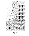
図8Aおよび9は、オートフィルアルゴリズムの実行の前後それぞれの、モデルの表示を示す。次のセクションでは、ユーザーが、多岐にわたる有用なトポロジーを簡単に指定できるオートフィルアルゴリズムの詳細を提示する。 8A and 9 show the display of the model before and after execution of the autofill algorithm. In the next section, we present details of the autofill algorithm that allows users to easily specify a wide variety of useful topologies.
特に、図9は、オートフィルアルゴリズムの使用の結果得られた、SFG106としてのワークフローモジュールを示す。リージェントバッチはアイコン160で表され、ディスペンス作業はアイコン162で表される。縦のバー 164a〜164b、および 1661,a〜1662,cはバッチメンバーであり、矢印168(白)はオートフィルアルゴリズムにより生成されたマテリアルフローアークである。このSFG106は、リージェント,aが、プレートの1,aおよび2,aの両方に調合されることを示す。矢印170(細い)はコンテナーシップを示す。
In particular, FIG. 9 shows a workflow module as
(オートフィルアルゴリズム)
以下のアルゴリズムは、図8に示すテンプレートを設けたユーザーからの図9に示すグラフ構造を生成する。
(Autofill algorithm)
The following algorithm generates the graph structure shown in FIG. 9 from the user who provided the template shown in FIG.
このシンプルで一般的なアルゴリズムを用いれば、ロー、コラム、もしくはプレートのすべてのウェルへのリージェントの配分、二つの1次元バッチの「クロスプロダクト」(図10および11)の生成、ローおよびコラムにわたるサンプルのプーリング(図12および13)、オペレーションのバッチからの選択、およびトランスポジションなどの有益なグラフ構造を、自動的にかつ多数生成できる。 With this simple and generic algorithm, the distribution of the regents to all wells of a row, column, or plate, the generation of two 1D batch "cross products" (Figures 10 and 11), across the rows and columns Many useful graph structures can be generated automatically, such as sample pooling (FIGS. 12 and 13), selection from batches of operations, and transposition.
(オートフィル例)
図10〜15および以下の説明には、正確かつ精細な構造がオートフィルアルゴリズムによって生成できるように、バッチレベルで様々な有益なトポロジーをどのように記述するかを説明する。各例を以下に示す。
・Cross:二つの1次元バッチのメンバーの間でのペア間の関係をすべて一組にして作成する。
・Pool:プールされた次元にわたってマッチするサンプルすべてをコンバインすることでバッチの次元を削減する。例としては、図6に示す、2Dバッチにおける各動物タイプに対する組織タイプのすべてをコンバインする。こうすることで、組織タイプの次元を削除した1Dバッチが生成される。
・Select:オリジナルバッチの座標のサブセットにマッチさせることで、バッチの一部のみを手順の後続ステップで用いることが可能になる。
・Transpose:オートフィルアルゴリズムがかけられる時はバッチの座標の順序を変更することで、ローがコラムに組み込まれ、その結果、様々な有益かつ実験的な構造を作成できる。例の一つとしては、一組のサンプル内で可能なすべての組み合わせを作り出すために、単一のバッチがそれ自身とクロスされる。
(Example of autofill)
FIGS. 10-15 and the following description illustrate how various useful topologies can be described at the batch level so that accurate and fine structures can be generated by the autofill algorithm. Each example is shown below.
Cross: Create all pairs of relationships between members of two one-dimensional batches.
Pool: Reduce batch dimensions by combining all matching samples across pooled dimensions. As an example, all of the tissue types for each animal type in the 2D batch shown in FIG. 6 are combined. By doing so, a 1D batch in which the dimension of the tissue type is deleted is generated.
Select: Matching a subset of the coordinates of the original batch allows only part of the batch to be used in subsequent steps of the procedure.
Transpose: When the autofill algorithm is applied, changing the coordinate order of the batch incorporates the rows into the column, thus creating a variety of useful and experimental structures. As one example, a single batch is crossed with itself to create all possible combinations within a set of samples.
(Cross)
図10および11は、プレート内で各サンプルを各ドラッグと組み合わせる「Cross」実験のセットアップとその結果を示す。特に、図10はクロス実験のセットアップを示す。図10に示すように、アイコン200で示すサンプルは、コラム軸に沿って単一の次元で配置される。アイコン202で示すドラッグは、ロー軸に沿って単一の次元で配置される。プレートは2D次元として定義され、そのローはドラッグバッチによって決まり、そのコラムはサンプルバッチによって決まる。オートフィルアルゴリズムは、プレートのx、yをサンプルのxとドラッグのyとマッチさせ、その結果、アイコン204が示すクロスプロダクトにおいて、ドラッグyとサンプルxが合成される。この結果が図11に示す精細なトポロジーである。コンバインオペレーションのバッチは、ユーザーによるこの情報の確認は一箇所でできるように、そのコラム軸の定義がサンプルから導かれ、ロー軸の定義はドラッグから導かれる。
(Cross)
Figures 10 and 11 show the setup and results of a "Cross" experiment that combines each sample with each drug in the plate. In particular, FIG. 10 shows a cross experiment setup. As shown in FIG. 10, the sample indicated by
図11は、その結果生成される、Samples.Columns およびDrugs.Rowsの軸定義を入力した後の、図10のクロス例に対して、オートフィルアルゴリズムによって生成された精細なトポロジーを示す。 FIG. 11 shows the result of Samples. Columns and Drugs. FIG. 11 shows the fine topology generated by the autofill algorithm for the cross example of FIG. 10 after inputting the Rows axis definition.
(Pooling)
図12および13は、「Pooling」実験のセットアップとその結果を示す。プーリングの目的の一つとしては、例えば、ローもしくはコラムのすべてのメンバーを単一のコンバインオペレーションに接続することである。もし、複数のコラムにわたってプールするなら、その結果のバッチはコラム軸を持たず、ローのみのはずである。特に、図12はプーリング例のセットアップを示す。「Drug」アイコン210は薬剤をしめし、「Sample」アイコン212はサンプルを示し、「Cross」アイコン214はクロスオペレーションを示し、「Pool」アイコン216はプーリングオペレーションを示す。図12に示すテンプレートは、図13に示すように、希望するプーリングをオートフィルアルゴリズム行わせる。これは、インデックス,xのプールバッチのメンバーがローxの2dバッチの全メンバーにマッチするので有効である。図12の2Dクロスプロダクトの各ローは単一のコンバインオペレーションにプールされる。結果得られるバッチは1次元であり、クロス_プロダクトのローと同じ数のローを有する。
(Pooling)
12 and 13 show the setup and results of a “Pooling” experiment. One purpose of pooling is, for example, to connect all members of a row or column to a single combine operation. If pooling across multiple columns, the resulting batch will have no column axis and should only be rows. In particular, FIG. 12 shows an example pooling setup. A “Drug” icon 210 indicates a drug, a “Sample” icon 212 indicates a sample, a “Cross” icon 214 indicates a cross operation, and a “Pool” icon 216 indicates a pooling operation. The template shown in FIG. 12 causes the desired pooling to be performed by the autofill algorithm, as shown in FIG. This is useful because the members of the pool batch with index, x match all members of the 2d batch of row x. Each row of the 2D cross product of FIG. 12 is pooled into a single combine operation. The resulting batch is one-dimensional and has the same number of rows as the cross_product rows.
図13は、図12図示のプーリング例を完遂させるためにオートフィルアルゴリズムをかけることで得られる接続性を示す。マテリアルフローは、コラムを削除するための、複数のローにわたるプーリングが後続するクロス構造を示す。 FIG. 13 shows the connectivity obtained by applying the autofill algorithm to complete the pooling example shown in FIG. The material flow shows a cross structure followed by pooling across multiple rows to remove columns.
(Selection)
図14はセレクト作業手順を示す。共通して必要なことは、与えられた一組のサンプルのサブセットに作業手順を行うことである。これは、オートフィルアルゴリズムを用いて、重要な軸のサブセットを特定することで完遂できる。次元数を同じに維持すれば、プーリングは起きない。図14の例では、ディスペンスバッチのプレート次元がサンプルのオリジナルバッチに対するプレート次元のサブレンジとして特定される。結果として、オートフィルアルゴリズムはディスペンスバッチのメンバーを、インデックスが正確にマッチするオリジナルバッチのメンバーに接続させるのみである。
(Selection)
FIG. 14 shows a selection work procedure. A common requirement is to perform a work procedure on a given subset of samples. This can be accomplished by identifying a subset of important axes using an autofill algorithm. If the number of dimensions is kept the same, pooling will not occur. In the example of FIG. 14, the plate dimension of the dispense batch is specified as a sub-range of the plate dimension for the original batch of samples. As a result, the autofill algorithm only connects the members of the dispense batch to the members of the original batch whose index matches exactly.
図14、Select。この構成は、5x4x3のバッチにおいて、3つのプレートから第一のプレートを選択する。インセット220は、オートフィルアルゴリズムを用いる前に、ユーザーによって要求される入力を示す。サンプルアイコン222はサンプルを表し、ディスペンスアイコン224はディスペンスオペレーションを表す。「5x4x1」の次元は、次元のサイズを示すのみである。実際のプレートもしくは選択されたプレートは、ユーザーによって指定されたディスペンスバッチ用の座標を介して決定する。例えば、プレートが「1」ではなく、「2、3」として特定される場合、次元サイズは5x4x2であり、オートフィルアルゴリズムは、第1ではなく、第2および第3のプレートにマッチする。 FIG. 14, Select. This configuration selects the first plate from three plates in a 5 × 4 × 3 batch. Inset 220 shows the input required by the user before using the autofill algorithm. Sample icon 222 represents a sample, and dispense icon 224 represents a dispense operation. The dimension “5 × 4 × 1” only indicates the size of the dimension. The actual or selected plate is determined via the dispense batch coordinates specified by the user. For example, if the plate is specified as “2, 3” instead of “1”, the dimension size is 5 × 4 × 2, and the autofill algorithm matches the second and third plates instead of the first.
(Transpose)
図15はトランスポーズ作業手順を図示する。バッチの配置方法を変更するのは有益な場合もある。例としては、単一のバッチから、可能なすべての組み合わせを作成する必要がある場合である。これは、オリジナルサンプルが二つのバッチに分けられ(ディスペンスオペレーション)、一つのバッチがロー軸に沿って配置され、他方がコラム軸に沿って配置される場合にのみ、上記のクロスパターンによって完遂される。このタスクは、バッチの一つに対して軸の順序が変更されるべきであるとの命令を出すことができれば、オートフィルアルゴリズムを用いて完遂できる。ランクプロパティを用いれば、違う順序にしたがって、関連するバッチに対してのみ、オートフィルアルゴリズムをマッチさせることができる。結果として、オリジナルサンプルバッチのメンバーxはトランスポーズされたディスペンスバッチ(Down)のメンバー,xにマッチする。図15は、サンプルのバッチをそれ自身とクロスするのに、このパターンがどのように用いられるかを示す。
(Transpose)
FIG. 15 illustrates the transpose procedure. It may be beneficial to change the way the batch is placed. An example is when it is necessary to create all possible combinations from a single batch. This is accomplished by the above cross pattern only when the original sample is divided into two batches (dispensing operation), one batch is placed along the row axis and the other is placed along the column axis. The This task can be accomplished using an autofill algorithm if one can instruct the batch order to be changed for one of the batches. Using rank properties, the autofill algorithm can be matched only to related batches according to a different order. As a result, member x of the original sample batch matches member x of the transposed dispense batch (Down). FIG. 15 shows how this pattern can be used to cross a batch of samples with itself.
インセット230は、図10および11に示すように、単一の1次元バッチをどのように分けてトランスポーズすれば、クロス作業手順のそれ自身とコンバインできるのかを示す。サンプルアイコン232はサンプルを示し、「Across」アイコン234はアクロスオペレーションを示し、「Down」アイコン236はダウンオペレーションを示し、「Cross」アイコン238はクロスオペレーションを示す。マッチングアルゴリズムによって使用される座標のディフォールト順序は、{Column, Row, Plate} の代わりに、{Row, Column Plate} の新しい順序を特定する「Rank」プロパティによってオーバーライドされる。結果として、オートフィルアルゴリズムは「Down」バッチのローを「Sample」バッチのコラムにマッチさせることで、「Down」が「Across」とクロスして、可能なすべての組み合わせの2−Dバッチを形成する。
Inset 230 shows how a single one-dimensional batch can be divided and transposed to combine with the cross work procedure itself, as shown in FIGS.
その他の様々な有用なパターンは特に、マッチアルゴリズムを様々な次元に沿ってシフトもしくはストレッチできるようにオフセットやストライドなどの他の指令が加えられた場合に、オートフィルアルゴリズムで解析される。 Various other useful patterns are analyzed by the autofill algorithm, especially when other commands such as offset and stride are added to allow the match algorithm to shift or stretch along various dimensions.
(オートフィルアルゴリズムエクステンション)
オートフィルアルゴリズムに対するこのエクステンションは、数学的に表示されうるパターンなら実際にどれでも含むように、自動的に生成可能な構造のクラスを一般化する。簡潔かつハイレベルな仕様から、オートフィルアルゴリズムは、このエクステンションを用いて、多次元スペースにおける組み合わされた複雑な作業手順やコンピュータ計算に対するモデルを生成できる。
(Autofill algorithm extension)
This extension to the autofill algorithm generalizes a class of structures that can be automatically generated to actually contain any mathematically displayable pattern. From concise and high-level specifications, the autofill algorithm can use this extension to generate models for combined complex work procedures and computer calculations in multidimensional spaces.
上記に論考した一般的なオートフィルアルゴリズムは、各インデックス位置でマッチした接続バッチのメンバーを接続し、空白位置はすべてのエントリーもしくは他の空白エントリにマッチする。このアルゴリズムはまた、バッチに含まれないが、バッチにエッジを介して接続されるオペレーションにも有効である。それらのオペレーションはインデックスプロパティを有しないため、接続されたバッチメンバーのインデックスプロパティすべてにマッチする。これは単一のオペレー損をバッチの全メンバーに接続するのに有効である。 The general autofill algorithm discussed above connects members of the connection batch that matched at each index position, and a blank position matches all entries or other blank entries. This algorithm is also useful for operations that are not included in a batch but are connected to the batch via an edge. Since those operations do not have an index property, they match all the index properties of the connected batch members. This is useful for connecting a single operating loss to all members of a batch.
このアルゴリズムに対するエクステンションは、各マッチを査定する前に、ユーザ定義のG.Index.eへの変換を適用するため、新しいアルゴリズムは以下のように生成される。一般化されたアルゴリズムからの変更部分は太字で強調して示す。 The extension to this algorithm is a user-defined G.D. Index. To apply the transformation to e, a new algorithm is generated as follows: Changes from the generalized algorithm are highlighted in bold.
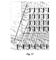
図16は、オートフィルアルゴリズムにSample 302とDispense 1 304の間で接続をシフトさせるマッチルールから発生したSFG200の簡略な一例である。図16に図示されたコラムマッチルールは、オートフィルアルゴリズム適用前に、Dispense 1 304の各メンバー304a〜304dごとに、個別に査定される。1を各メンバー304a〜304dのコラム位置に加算すると、接続が左へシフトする。例えば、Dispense 1 304の第4メンバー304dは、Sample302の第5メンバーの302eに接続される。また、Dispense 1 304は4つのメンバーを含むのみである。オートフィルアルゴリズムは、マッチのないメンバーを自動的に削除する。
FIG. 16 is a simple example of an
マッチルールに若干の変更を加えたものを、図17のSFG320で図示するが、ここでは、同様の4つのメンバーという結果がでているが、シフトはない。図17では、コラムマッチルールの条件式が、Column0に対してマッチするものがないことを確認するために使用されて、他の位置は影響を受けない。この場合、シフトはない。
A slightly modified match rule is illustrated by
図18は、SFG350で表されるような、有益な構造を生成するための、オートフィルアルゴリズムのパワーとマッチルールエクステンションの説明に対する、より高度な例を示している。統計的な観点から、一組のreagent354に対するすべての可能な組み合わせを用いて、一組のSample352に実験を試みることが必要な場合がある。オートフィルアルゴリズムとマッチルールエクステンションを用いれば、そうした実験の正確なグラフ表示350を簡単に生成できる。
FIG. 18 shows a more advanced example for the description of the power of the autofill algorithm and the match rule extension to generate a useful structure, such as that represented by SFG350. From a statistical point of view, it may be necessary to experiment with a set of
図18の例では、マッチルールがどのようにオリジナルサンプルセットもしくはbatch352を同時にトランスポーズしてペアリングの重複を避け、望ましい上位もしくは下位のトライアングルマトリックスが得られるかが示されている。この例は図15の図示と同様であり、original sample352が二つのバッチ(Dispense Operations Across 354およびDown356)に分けられており、バッチの一つがロー軸に沿って配置されており、他方がコラム軸に沿って配置されている。Across batch354に対するペアの重複は、コラムがロー同等か大きい場合にはすべてのマッチングを避け、マッチングをチェックする前にローとコラムのインデックス位置をトランスポーズすることで、防ぐことができる。選択されたアイコンの間のdark line358は、オートフィルによって生成された接続のいくつかを強調する。Cross batch360の項目に対するインデックスは、それらのoriginal Sample batch352との関係を、適正に指し示す。これは、ユーザーがバッチレベルで定義する接続に沿って、バッチからバッチへ、オートフィルアルゴリズムと自動座標が伝播していることの自然な結果である。
In the example of FIG. 18, it is shown how the match rule simultaneously transposes the original sample set or
(マニュアルオーバーライドに対するオートフィルアルゴリズムのエクステンション)
上記で論考されたオートフィルアルゴリズムでは、フローグラフのバッチメンバー間の接続はすべて、アルゴリズムによって決定される。これらの結果は、アルゴリズムを用いた後で、自動とマニュアルの接続を組み合わせるために、ユーザーによって変更が可能である。しかし、この方法は、バッチサイズとマッチルールが変更されるために、アルゴリズムが繰り返し再実行されるダイナミックな実行には好適とはいえない。ダイナミックなアルゴリズムの実行においては、オートフィルの結果に対してマニュアルで加えた変更は、次の実行で消去される。この問題点を解決するために、その後のオートフィルアルゴリズムの実行結果に影響を与える方法での、モデルのマニュアル編集を保存する新規な方法を以下に提起する。モデリングのエクステンションとオートフィルアルゴリズムへの変更を以下に説明する。
(Extension of autofill algorithm for manual override)
In the autofill algorithm discussed above, all connections between batch members of the flow graph are determined by the algorithm. These results can be changed by the user after using the algorithm to combine automatic and manual connections. However, this method is not suitable for dynamic execution where the algorithm is repeatedly re-executed because the batch size and match rules are changed. In the execution of the dynamic algorithm, any manual changes made to the autofill results are erased in the next execution. In order to solve this problem, a new method for saving the manual editing of the model in a way that affects the execution result of the subsequent autofill algorithm is presented below. Modeling extensions and changes to the autofill algorithm are described below.
図19においては、バッチXはバッチYに接続されている。結果として、バッチXの各メンバーは、オートフィルアルゴリズムによる「automatic」接続によって、バッチYのメンバーそれぞれに自動的に接続される。 In FIG. 19, batch X is connected to batch Y. As a result, each member of batch X is automatically connected to each member of batch Y by an “automatic” connection with an autofill algorithm.
オリジナルなシステムでは、ユーザーが接続を削除したい場合には、例えば、バッチXの1,AとバッチYの1,A間において、ユーザーは、それらの間で「automatic」接続を削除できた。しかしながら、オートフィルアルゴリズムが再実行されると、ユーザーの意思に反して、この削除された接続が復元する。
In the original system, if the user wanted to delete a connection, for example, between
バッチサイズやマッチルールなどのパラメータが変更されると自動接続が再計算されるダイナミックユーザーインターフェースをサポートするには、マニュアルによる変更を保存する方法が求められる。二通りのマニュアル変更が可能である。「automatic」エッジの削除(すなわち、削除)、および、オートフィルアルゴリズムであれば作成されなかったエッジの追加(すなわち、追加)である。 To support a dynamic user interface where automatic connections are recalculated when parameters such as batch size and match rules change, a way to save manual changes is required. Two manual changes are possible. “Automatic” edge deletion (ie, deletion) and edge addition (ie, addition) that was not created by the autofill algorithm.
新規の実行の際には、その場所の間に「NoConnect」エッジを追加することでautomatic」エッジが永久的に削除される。この「NoConnect」エッジは、新規のオートフィルアルゴリズムによって遵守されるので、自動エッジは作成されない。「NoConnect」エッジは図20に白で表示している。 In a new run, the “automatic” edge is permanently removed by adding a “NoConnect” edge between the locations. This “NoConnect” edge is respected by the new autofill algorithm, so no automatic edge is created. The “No Connect” edge is displayed in white in FIG.
この「NoConnect」エッジはユーザーから見えないようにすることも可能であるが、「NoConnect」エッジは可視にすることで、ユーザーが、自動接続を復元させたい場合に、「NoConnect」エッジを削除することを認識できるようにすることが好ましいと考えられる。 The “NoConnect” edge can be made invisible to the user, but the “NoConnect” edge is made visible so that when the user wants to restore the automatic connection, the “NoConnect” edge is deleted. It would be preferable to be able to recognize this.
マニュアル接続を保存するには、オートフィルアルゴリズムの再実行前に、自動接続のみが削除される。図21は、Xにおける2,AとYにおける1,A間にマニュアル接続を追加した結果を示す。 To save a manual connection, only the automatic connection is deleted before the autofill algorithm is re-executed. FIG. 21 shows the result of adding a manual connection between 2A in X and 1A in Y.
オートフィルのダイナミックな実行は、以下の擬似コード仕様で要約できる。 The dynamic execution of autofill can be summarized by the following pseudo code specification:
(その他の適用)
上記の各例は、実験手順の観点から説明されるが、純粋に数学的なモデリングやコンピュータ計算にも同様に適用可能である。例として、バッチや自動的に生成された接続は生物学的システムの空間的および時間的なモデルを生成するのに使用可能である。バッチの各エレメントは、化学種の反応や凝縮に対応し、エッジは化学種の凝縮の変化を引き起こす反応内外の科学的移動に対応する。オートフィルアルゴリズムおよびマッチルールエクステンションによって、ユーザーにとって、それらのシステムや他のコンピューターシステムの複雑な有限エレメントモデルを、シンプルなアイコン表示を用いて迅速に生成することが可能になる。
(Other application)
Each of the above examples is described in terms of experimental procedures, but is equally applicable to purely mathematical modeling and computer calculations. As an example, batches and automatically generated connections can be used to generate spatial and temporal models of biological systems. Each element of the batch corresponds to a reaction or condensation of a chemical species, and an edge corresponds to a scientific movement inside or outside the reaction that causes a change in the condensation of the chemical species. Autofill algorithms and match rule extensions allow users to quickly generate complex finite element models of those systems and other computer systems using simple icon displays.
関連分野の当業者であれば、図2〜18と本明細書の詳細な説明に基づいて、速やかにソースを作成することが可能であろう。 One of ordinary skill in the relevant art will be able to quickly create a source based on FIGS. 2-18 and the detailed description herein.
ワークフローモデリングにおけるオートフィリングの機器や方法に対する各実施形態や実施例が、本明細書において、実例紹介として説明されているが、関連分野の当業者であれば気づくように、種々の均等な変更が、本発明の精神と範囲を逸脱することなく可能である。本発明の記載内容は、上記にその全体を説明した例示のコンピューターシステムに限らず、他のプロセッサー制御システムに適用可能である。同様に、本発明の記載内容は、上記にその全体を説明した例示のワークフローモデリング手段に限らず、他のワークフローモデリング手段に適用可能である。 Each embodiment or example for an autofilling device or method in workflow modeling is described herein as an example introduction, but as those skilled in the relevant art will be aware, various equivalent changes may be made. This is possible without departing from the spirit and scope of the present invention. The description of the present invention is not limited to the exemplary computer system described in its entirety above, but can be applied to other processor control systems. Similarly, the description of the present invention is not limited to the exemplary workflow modeling means described above in its entirety, but can be applied to other workflow modeling means.
上記に説明した各実施形態を組み合わせることで、さらなる実施形態を提供可能である。本明細書に記載、および/もしくはアプリケーションデータシートに挙げられたすべての、米国特許、米国特許出願広報、米国特許出願、外国特許、外国特許出願、非特許出版物、かつ以下に挙げる同一出願人による仮特許出願−含むが限定は受けない−は、その記載全容において、参照され本書に組み込まれる。
Serial No. 60/454,756, filed March 14, 2003, 「METHOD, APPARATUS AND ARTICLE FOR GRAPHICAL MANIPULATION OF WORKFLOW USING EQUATIONS;Serial No. 60/493,749, filed August 8, 2003, 「BATCH−BASED METHOD AND TOOL FOR GRAPHICAL MANIPULATION OF WORKFLOWS」;Serial No. 60/505,096, filed September 22, 2003, 「BATCH−BASED METHOD AND TOOL FOR GRAPHICAL MANIPULATION OF WORKFLOWS」;Serial No. 60/543,859, filed February 11, 2004, 「BATCH−BASED METHOD AND TOOL FOR GRAPHICAL MANIPULATION OF WORK FLOWS」;Serial No. 60/493, 748, filed August 8, 2003, 「CLOSED LOOP INTEGRATION OF IN SILICO AND PHYSCIAL MODELING」;Serial No. 60/508,109, filed October 2, 2003, 「CLOSED LOOP INTEGRATION OF IN SILICO AND PHYSCIAL MODELING」。本発明の態様は、必要であれば、変更を加えることで、様々な特許、出願、印刷物のシステム、回路、概念を採用し、本発明にさらなる実施手形態を提供することが可能である。
Further embodiments can be provided by combining the embodiments described above. All U.S. patents, U.S. patent application publications, U.S. patent applications, foreign patents, foreign patent applications, non-patent publications, and the same applicants listed below, as described herein and / or listed in application data sheets Provisional patent application-including but not limited to-is incorporated herein by reference in its entirety.
Serial No. 60 / 454,756, filled March 14, 2003, "METHOD, APPARATUS AND ARTICLE FOR GRAPHICAL MANIPULATION OF WORKFLOW USING EQUATIONS; Serial No. 60/493, 749 MANIPULATION OF WORKFLOWS "; 60 / 505,096, filled September 22, 2003, “BATCH-BASED METHOD AND TOOL FOR GRAPHICAL MANIPULATION OF WORKFLOWS”; 60 / 543,859, filled February 11, 2004, “BATCH-BASED METHOD AND TOOL FOR GRAPHICAL MANIPULATION OF WORK FLOWS”; 60/493, 748, filled August 8, 2003, “CLOSED LOOP INTEGRATION OF IN SILICON AND PHYSICAL MODELING”; 60/508, 109, filled October 2, 2003, “CLOSED LOOP INTEGRATION OF IN SILICON AND PHYSICAL MODELING”. Aspects of the present invention can be modified, if necessary, to employ various patents, applications, printed systems, circuits, concepts, and provide further embodiments to the present invention.
上記詳細説明を鑑みて、上記およびそれ以外の変更を加えることが可能である。一般的には、添付された請求項において、そこに記載された用語は、本明細書および開示された実施形態と請求項において、本発明に何ら限定を加えるものではないが、請求項により実施されるすべてのバッチベースの作業手順設計を含むものである。したがって、本発明はその開示による限定は受けないが、その範囲はもっぱら添付の請求項によって決定される。 In light of the above detailed description, the above and other modifications can be made. In general, in the appended claims, the terminology described therein shall not be construed as limiting the invention in the specification and the disclosed embodiments and claims, but may be implemented according to the claims. Includes all batch-based work procedure designs to be performed. Accordingly, the invention is not limited by the disclosure, but the scope thereof is determined solely by the appended claims.
Claims (28)
少なくとも二つの階層型ノードのデジタル表示を作成し、前記各階層型ノードが各階層型ノードの多数の次元を定義する各次元数を自身に関連付け、前記各階層型ノードの各次元が互いに対し定義された順序を有し、各次元がそれぞれの多数のメンバーを定義する関連サイズを有し、
前記階層型ノードの少なくともいくつかの間の接続を定義する多数の階層型エッジのデジタル表示を作成し、前記階層型エッジの少なくとも第1のエッジが、前記少なくとも二つの前記階層ノードの第1および第2のノードとの間に接続を定義し、
前記階層型エッジの各共有エッジによって接続された階層型ノードの多数のペアのそれぞれに対して、多数のマッチルールの少なくとも一つを前記階層型ノードのペアと関連付け、前各記マッチルールは前記各ペアの階層型ノード間に、少なくとも一つのマトリックス変換を定義し、前記各ペアの前記階層型ノードのメンバーに前記マトリックス変換を適用することで、生成される一組の原始ノードと原始エッジを定義し、多数のマッチルールの第1ルールは、前記第1および第2階層型ノード間に第1マトリックス変換を定義する、方法。 A method that uses a digital model of the flow process,
Create a digital representation of at least two hierarchical nodes, each hierarchical node associates itself with a number of dimensions that define a number of dimensions of each hierarchical node, and each dimension of each hierarchical node defines each other Each dimension has an associated size that defines a respective number of members,
Creating a digital representation of a number of hierarchical edges defining connections between at least some of the hierarchical nodes, wherein at least a first edge of the hierarchical edges is a first and second of the at least two hierarchical nodes; Define a connection with the other node,
For each of the multiple pairs of hierarchical nodes connected by each shared edge of the hierarchical edge, associate at least one of multiple match rules with the pair of hierarchical nodes, By defining at least one matrix transformation between the hierarchical nodes of each pair and applying the matrix transformation to the members of the hierarchical nodes of each pair, a set of generated primitive nodes and primitive edges is generated. A method wherein the first rule of the multiple match rules defines a first matrix transformation between the first and second hierarchical nodes.
前記少なくとも二つの階層型ノードの第1の階層型ノードを表わす第1のアイコンの選択を定義し、第1の階層型ノードに対する次元の総数を示す次元数と各次元のサイズを定義する第1組のユーザー入力を受領し、
前記少なくとも二つの階層型ノードの第2の階層型ノードを表わす第1のアイコンの選択を定義し、第2の階層型ノードに対する次元の総数を示す次元数と各次元のサイズを定義する第2組のユーザー入力を受領する、方法。 The method of claim 1, further comprising:
Defining a selection of a first icon representing a first hierarchical node of the at least two hierarchical nodes and defining a number of dimensions indicating a total number of dimensions for the first hierarchical node and a size of each dimension Receive a set of user input,
Defining a selection of a first icon representing a second hierarchical node of the at least two hierarchical nodes, and defining a number of dimensions indicating the total number of dimensions for the second hierarchical node and a size of each dimension A method of receiving a set of user input.
前記第1階層型ノードから前記第2階層型ノードまで延びるエッジを表わす第1アイコンを定義する第3組のユーザー入力を受領する、方法。 The method of claim 2, further comprising:
Receiving a third set of user inputs defining a first icon representing an edge extending from the first hierarchical node to the second hierarchical node.
前記少なくとも二つの階層型ノードの前記第1の階層型ノードを表わす第1のアイコンの選択と前記第1階層型ノードの人間読み取り可能の名称を定義し、前記第1階層型ノードの次元の総数を示す次元数と、各次元のサイズと、各次元の人間読み取り可能の名称を定義する第1組のユーザー入力を受領する、方法。 The method of claim 1, further comprising:
Selecting a first icon representing the first hierarchical node of the at least two hierarchical nodes and defining a human readable name for the first hierarchical node, and the total number of dimensions of the first hierarchical node Receiving a first set of user inputs defining the number of dimensions, the size of each dimension, and a human readable name for each dimension.
前記少なくとも二つの階層型ノードの前記第1の階層型ノードを表わす第1のアイコンの選択と前記第1階層型ノードの人間読み取り可能の名称を定義し、前記第1階層型ノードの次元の総数を示す次元数と、次元における互いの順序と、各次元のサイズを定義する第1組のユーザー入力を受領する、方法。 The method of claim 1, further comprising:
Selecting a first icon representing the first hierarchical node of the at least two hierarchical nodes and defining a human readable name for the first hierarchical node, and the total number of dimensions of the first hierarchical node Receiving a first set of user inputs defining the number of dimensions, the order of each other in the dimensions, and the size of each dimension.
前記各階層型ノードに対して、各次元を充填する多数の原始ノードのデジタル表示を、前記多数の次元と前記各階層型ノードの次元のサイズとに基づき自動的に作成する、方法。 The method of claim 1, further comprising:
A method of automatically creating, for each hierarchical node, a digital representation of a number of primitive nodes filling each dimension based on the number of dimensions and the size of each hierarchical node dimension.
前記階層型エッジの各共有エッジによって接続された階層型ノードの各ペアに対して、原始ノード間に原始エッジのデジタル表示を、前記階層型ノードの各ペアに関連した前記マッチルールによって定義された前記マトリックス変換に基づき自動的に作成する、方法。 The method of claim 6, further comprising:
For each pair of hierarchical nodes connected by each shared edge of the hierarchical edge, a digital representation of the primitive edge between the primitive nodes is defined by the match rules associated with each pair of hierarchical nodes A method of automatically creating based on the matrix transformation.
前記階層型ノードの少なくとも一つ、もしくは前記階層型エッジの少なくとも一つに対する変化を検知し、
前記検知された変化に対応して、前記各階層型ノードに対して、
前記各次元を充填する多数の原始ノードのデジタル表示を、前記多数の次元と前記各階層型ノードのそれぞれの次元のサイズとに基づき自動的に作成する、方法。 The method of claim 7, further comprising:
Detecting a change to at least one of the hierarchical nodes or at least one of the hierarchical edges;
In response to the detected change, for each hierarchical node,
A method of automatically creating a digital representation of a number of primitive nodes filling each dimension based on the number of dimensions and the size of each dimension of each hierarchical node.
前記階層型ノードの少なくとも一つ、もしくは前記階層型エッジの少なくとも一つに対する変化を検知し、
前記検知された変化に対応して、前記各階層型ノードに対して、
前記各次元を充填する多数の原始ノードのデジタル表示を、前記多数の次元と前記各階層型ノードのそれぞれの次元のサイズとに基づき自動的に再作成し、原始ノード間に原始エッジのデジタル表示を、階層型ノードの各ペアに関連した前記マッチルールによって定義された前記マトリックス変換に基づき自動的に作成する、方法。 The method of claim 7, further comprising:
Detecting a change to at least one of the hierarchical nodes or at least one of the hierarchical edges;
In response to the detected change, for each hierarchical node,
A digital representation of a number of primitive nodes filling each dimension is automatically recreated based on the number of dimensions and the size of each dimension of each hierarchical node, and a digital representation of the primitive edge between the primitive nodes Is automatically created based on the matrix transformation defined by the match rules associated with each pair of hierarchical nodes.
ユーザーが、前記マッチルールの少なくとも一つの、前記原始ノードの少なくとも一つもしくは前記原始エッジの少なくとも一つへの適用の抑制を指示することを決定し、
ユーザー指示による、前記少なくとも一つのマッチルールの、前記原始ノードの少なくとも一つもしくは前記原始ノードの少なくとも一つへの適用の抑制に基づき、前記原始ノードの少なくとも一つもしくは前記原始エッジの少なくとも一つの再作成を選択的に抑制する、方法。 The method of claim 9, further comprising:
The user decides to direct the application of at least one of the match rules to at least one of the source nodes or at least one of the source edges;
At least one of the source nodes or at least one of the source edges based on user instructions to suppress application of the at least one match rule to at least one of the source nodes or at least one of the source nodes. A method that selectively suppresses re-creation.
前記原始ノードと原始エッジの可視表示を生成する、方法。 The method of claim 1, further comprising:
Generating a visual representation of the source node and source edge;
多数のトランスデューサーを駆動するために、少なくとも前記原始ノードのいくつかと原始エッジのいくつかに対応する多数のトランスデューサー駆動信号を生成する、方法。 The method of claim 11, further comprising:
Generating a plurality of transducer drive signals corresponding to at least some of the primitive nodes and some of the primitive edges to drive a plurality of transducers.
少なくとも二つの階層型ノードのデジタル表示を作成する手段を備え、前記各階層型ノードがそれ自身を各階層型ノードの多数の次元を定義する各次元数と関連付け、前記各階層型ノードの各次元が互いに対して定義された順序を有し、各次元がそれぞれの多数のメンバーを定義する関連サイズを有するものであり、
前記階層型ノードの少なくともいくつかの間で接続を定義する多数の階層型エッジのデジタル表示を作成する手段を備え、前記階層型エッジの少なくとも第1のエッジが、前記少なくとも二つの階層ノードの第1および第2のノードとの間に接続を定義するものであり、
多数のマッチルールの少なくとも一つを、前記階層型エッジの各共有エッジによって接続された階層型ノードの多数のペアに対して、一対の階層型ノードに関連付ける手段を備え、前記各マッチルールは前各ペアの記階層型ノード間に少なくとも一つのマトリックス変換を定義し、前記各ペアの階層型ノードのメンバーに前記マトリックス変換を適用することで生成される一組の原始ノードと原始エッジを定義し、
前記多数のマッチルールの第1ルールは前記第1ノードと第2ノード間の第1マトリックス変換を定義する、システム。 A system that models highly parallel processing, where the parallel path operates on material or data that undergoes reorganization, such as combining and / or splitting,
Means for creating a digital representation of at least two hierarchical nodes, wherein each hierarchical node associates itself with a number of dimensions defining a number of dimensions of each hierarchical node, and each dimension of each hierarchical node Have an order defined with respect to each other, and each dimension has an associated size defining a respective number of members,
Means for creating a digital representation of a number of hierarchical edges defining connections between at least some of the hierarchical nodes, wherein at least a first edge of the hierarchical edges is a first and second of the at least two hierarchical nodes. Define a connection with the second node,
Means for associating at least one of multiple match rules with a pair of hierarchical nodes for multiple pairs of hierarchical nodes connected by each shared edge of the hierarchical edges, wherein each match rule Define at least one matrix transformation between each pair of hierarchical nodes, and define a set of primitive nodes and primitive edges generated by applying the matrix transformation to members of each pair of hierarchical nodes ,
The system wherein a first rule of the multiple match rules defines a first matrix transformation between the first node and a second node.
プロセッサーと、
前記プロセッサーによって実行される指示を格納するコンピューター読み取り可能メモリを備え、
少なくとも二つの階層型ノードのデジタル表示を作成する前記手段は前記コンピューター読み取り可能メモリに格納された第1組の指示を備え、前記階層型ノードの少なくともいくつかの間の接続を定義する多数の階層型エッジのデジタル表示を作成する前記手段は、前記コンピューター読み取り可能メモリに格納された第2組の指示を備え、多数のマッチルールの少なくとも一つを、前記階層型エッジの各共有エッジによって接続された階層型ノードの多数のペアに対して、一対の階層型ノードに関連付ける前記手段は前記コンピューター読み取り可能メモリに格納された第3組の指示を備える、システム。 14. The system according to claim 13, further comprising:
A processor;
Comprising a computer readable memory for storing instructions to be executed by the processor;
The means for creating a digital representation of at least two hierarchical nodes comprises a first set of instructions stored in the computer readable memory, wherein a plurality of hierarchical edges defining connections between at least some of the hierarchical nodes Said means for creating a digital representation of a hierarchy comprising a second set of instructions stored in said computer readable memory, wherein at least one of a plurality of match rules is connected by each shared edge of said hierarchical edge The means for associating a plurality of pairs of type nodes with a pair of hierarchical nodes comprises a third set of instructions stored in the computer readable memory.
前記プロセッサーに連結されて、前記階層型ノード、前記階層型エッジ、前記原始ノードおよび原始エッジに動作可能なディスプレイを備える、システム。 14. The system according to claim 13, further comprising:
A system coupled to the processor, comprising a display operable on the hierarchical node, the hierarchical edge, the primitive node and the primitive edge.
一つ以上のロボット機器に制御信号を与える連結可能な出力ポートを備える、システム。 14. The system according to claim 13, further comprising:
A system comprising a connectable output port for providing control signals to one or more robotic devices.
少なくとも二つの階層型ノードを備え、前記各階層型ノードは、前記各階層型ノードの多数の次元を定義する各次元数をそれ自身に関連付け、各階層型ノードの各次元がお互いに対し定義された順序を有し、各次元がそれぞれの多数のメンバーを定義する関連サイズを有するものであり、
前記階層型ノードの少なくともいくつかの間で接続を定義する多数の階層型エッジを備え、前記階層型エッジの少なくとも第1のエッジが、前記少なくとも二つの前記階層ノードの第1および第2のノードとの間に接続を定義するものであり、
多数のマッチルールを備え、各前記マッチルールは前記階層型エッジの共通エッジによって接続される階層型ノードの各ペア間に少なくとも一つのマトリックス変換を定義し、前記階層型ノードの各ペアにおける階層型ノードのメンバーに前記マトリックス変換を適用することで、生成される一組の原始ノードと原始エッジを定義し、前記多数のマッチルールの第1ルールは前記第1および第2階層型ノード間の第1マトリックス変換を定義する、コンピューター読み取り可能媒体。 A computer readable medium that stores a data structure describing a flow process,
Comprising at least two hierarchical nodes, each hierarchical node associating itself with a number of dimensions defining a number of dimensions of each hierarchical node, wherein each dimension of each hierarchical node is defined with respect to each other Each dimension has an associated size that defines a respective number of members,
A plurality of hierarchical edges defining connections between at least some of the hierarchical nodes, wherein at least a first edge of the hierarchical edge is connected to first and second nodes of the at least two of the hierarchical nodes Define the connection between them,
Comprising a plurality of match rules, wherein each match rule defines at least one matrix transformation between each pair of hierarchical nodes connected by a common edge of the hierarchical edge, and the hierarchical type in each pair of hierarchical nodes By applying the matrix transformation to the members of the node, a set of generated primitive nodes and primitive edges is defined, and the first rule of the multiple match rules is a first rule between the first and second hierarchical nodes. A computer-readable medium that defines a one-matrix transformation.
各メンバーは基本オペレーションもしくは基本マテリアルを表す、コンピューター読み取り可能媒体。 A computer readable medium according to claim 17, comprising:
A computer readable medium where each member represents a basic operation or basic material.
各メンバーは情報の基本部分を表す、コンピューター読み取り可能媒体。 A computer readable medium according to claim 17, comprising:
A computer-readable medium where each member represents a basic piece of information.
各メンバーは基本オペレーション、基本マテリアル、もしくは別の階層ノードの一つを表す、コンピューター読み取り可能媒体。 A computer readable medium according to claim 17, comprising:
A computer-readable medium where each member represents one of the basic operations, basic materials, or another hierarchical node.
各メンバーは前記次元に沿って順序づけられる、コンピューター読み取り可能媒体。 A computer readable medium according to claim 17, comprising:
A computer readable medium in which each member is ordered along the dimension.
前記第1および第2階層型ノードの少なくとも一つの前記次元数は3つであり、各次元はX−軸、前記X−軸に直行するY−軸、前記X−軸とY−軸の両方に直行するZ−軸に相当する、コンピューター読み取り可能媒体。 A computer readable medium according to claim 17, comprising:
The number of dimensions of at least one of the first and second hierarchical nodes is three, and each dimension is an X-axis, a Y-axis orthogonal to the X-axis, and both the X-axis and the Y-axis. A computer-readable medium corresponding to the Z-axis that goes directly to
各メンバーは情報の基本部分を表す、コンピューター読み取り可能媒体。
前記第1および第2階層型ノードの少なくとも一つの前記次元数は2つであり、各次元はローとローに直行するコラムに相当する、コンピューター読み取り可能媒体。 A computer readable medium according to claim 17, comprising:
A computer-readable medium where each member represents a basic piece of information.
The computer-readable medium, wherein the number of dimensions of at least one of the first and second hierarchical nodes is two, and each dimension corresponds to a row and a column orthogonal to the row.
多数の階層型ノードのそれぞれに対して、各階層型ノードの少なくとも一つのデカルト次元を一部充填する多数の原始ノードを自動的に作成し、
前記自動的に作成された原始ノード間の多数の基本エッジ接続を、前記階層型ノードの接続ペアに関連するマッチルールに基づいて自動的に作成し、前記マッチルールは前記階層型ノードの接続ペアの階層型ノード間に少なくとも一つのマトリックス変換を定義する、方法。 Lower level of process flow in the form of basic connection between the source node and the source node by adopting advanced composition in the form of layered edge that defines the indicated connection between the node and the source node A method of expressing details in
For each of a number of hierarchical nodes, automatically create a number of primitive nodes that partially fill at least one Cartesian dimension of each hierarchical node;
A number of basic edge connections between the automatically created primitive nodes are automatically created based on match rules associated with the connection pairs of the hierarchical nodes, and the match rules are connected pairs of the hierarchical nodes. Defining at least one matrix transformation between hierarchical nodes.
プロパティを前記原始ノードの少なくともいくつかに関連付け、前記原始ノードに関連付けられたプロパティは、前記原始ノードを前記マッチルールを介して定義する前記階層型ノードの各次元に割り当てられたプロパティに対応する、方法。 25. The method of claim 24, further comprising:
Associating a property with at least some of the source nodes, the property associated with the source node corresponding to a property assigned to each dimension of the hierarchical node defining the source node via the match rule; Method.
第1の階層型ノードは第1のマテリアルに相当し、第2の階層型ノードは第2のマテリアルに相当し、第3の階層型ノードは前記第1および第2のマテリアルに対して行われるオペレーションに相当し、第1のエッジは前記第1の階層型ノードを前記第3の階層型ノードに接続し、第2のエッジは前記第2の階層型ノードを前記第3の階層型ノードに接続する、方法。 25. The method of claim 24, comprising:
The first hierarchical node corresponds to the first material, the second hierarchical node corresponds to the second material, and the third hierarchical node is performed on the first and second materials. The first edge connects the first hierarchical node to the third hierarchical node, and the second edge connects the second hierarchical node to the third hierarchical node. How to connect.
各階層型ノードの少なくとも一つのデカルト次元を一部充填する多数の原始ノードの自動的作成において、前記第1の階層型ノードのローを表す多数の原始ノードを作成し、前記第2の階層型ノードのコラムを表す多数の原始ノードを作成し、前記第3の階層型ノードを表す原始ノードの多数のローとコラムを作成し、前記第3の階層型ノードを表す前記多数のローは前記第1の階層型ノードの多数のローとマッチし、前記第3の階層型ノードを表す前記多数のコラムは前記第2の階層型ノードの多数のコラムと合致する、方法。 27. The method of claim 26, further comprising:
In automatically creating a number of primitive nodes partially filling at least one Cartesian dimension of each hierarchical node, creating a number of primitive nodes representing the rows of the first hierarchical node, the second hierarchical type Creating a number of primitive nodes representing columns of nodes, creating a number of rows and columns of primitive nodes representing the third hierarchical node, and the plurality of rows representing the third hierarchical node The method matches multiple rows of one hierarchical node, and the multiple columns representing the third hierarchical node match multiple columns of the second hierarchical node.
前記自動的に作成された原始ノード間の多数の基本エッジ接続の、前記階層型ノードの接続ペアに関連するマッチルールに基づく自動的作成において、前記第1の階層型ノードの各ローを表す多数の原始ノードのそれぞれから、前記第3の階層型ノードの各ローにおける前記原始ノードのそれぞれまでのエッジ接続を作成し、前記第2の階層型ノードの各コラムを表す多数の原始ノードのそれぞれから、第3の階層型ノードの各コラムにおける前記原始ノードのそれぞれまでのエッジ接続を作成する、方法。 28. The method of claim 27, further comprising:
In automatic creation of a number of basic edge connections between the automatically created primitive nodes based on match rules associated with connection pairs of the hierarchical nodes, a number representing each row of the first hierarchical node An edge connection from each of the primitive nodes to each of the primitive nodes in each row of the third hierarchical node, and from each of a number of primitive nodes representing each column of the second hierarchical node Creating an edge connection to each of the source nodes in each column of the third hierarchical node.
Applications Claiming Priority (5)
| Application Number | Priority Date | Filing Date | Title |
|---|---|---|---|
| US45475603P | 2003-03-14 | 2003-03-14 | |
| US49374903P | 2003-08-08 | 2003-08-08 | |
| US50509603P | 2003-09-22 | 2003-09-22 | |
| US54385904P | 2004-02-11 | 2004-02-11 | |
| PCT/US2004/007748 WO2004086174A2 (en) | 2003-03-14 | 2004-03-11 | Batch-based method and tool for graphical manipulation of workflows |
Publications (2)
| Publication Number | Publication Date |
|---|---|
| JP2006520502A true JP2006520502A (en) | 2006-09-07 |
| JP2006520502A5 JP2006520502A5 (en) | 2007-07-12 |
Family
ID=33102444
Family Applications (1)
| Application Number | Title | Priority Date | Filing Date |
|---|---|---|---|
| JP2006507157A Pending JP2006520502A (en) | 2003-03-14 | 2004-03-11 | Batch-based methods and means for graphical manipulation of workflows |
Country Status (6)
| Country | Link |
|---|---|
| US (1) | US7010760B2 (en) |
| EP (1) | EP1609049A4 (en) |
| JP (1) | JP2006520502A (en) |
| AU (1) | AU2004222903B2 (en) |
| CA (1) | CA2518884A1 (en) |
| WO (1) | WO2004086174A2 (en) |
Cited By (1)
| Publication number | Priority date | Publication date | Assignee | Title |
|---|---|---|---|---|
| JP2023507097A (en) * | 2019-12-17 | 2023-02-21 | ベックマン コールター, インコーポレイテッド | Computer-implemented liquid handler protocol |
Families Citing this family (18)
| Publication number | Priority date | Publication date | Assignee | Title |
|---|---|---|---|---|
| US7680797B1 (en) | 2003-07-25 | 2010-03-16 | Verizon Data Services Llc | Methods and systems for providing a data access layer |
| US8645547B1 (en) | 2003-07-25 | 2014-02-04 | Verizon Data Services Llc | Methods and systems for providing a messaging service |
| US20050065767A1 (en) * | 2003-08-08 | 2005-03-24 | Teranode Corporation | Closed loop integration of digital models of in silico systems and experimental procedures |
| US8285856B1 (en) | 2004-07-23 | 2012-10-09 | Verizon Data Services Llc | Methods and systems for integrating a messaging service with an application |
| US8347203B1 (en) * | 2004-07-23 | 2013-01-01 | Verizon Data Services Llc | Methods and systems for defining a form navigational structure |
| US8300062B2 (en) * | 2005-04-18 | 2012-10-30 | Steve Tsang | Method, system and computer program for using a suggestive modeling interface |
| US7672865B2 (en) * | 2005-10-21 | 2010-03-02 | Fair Isaac Corporation | Method and apparatus for retail data mining using pair-wise co-occurrence consistency |
| US20070250505A1 (en) * | 2006-04-25 | 2007-10-25 | Sbc Knowledge Ventures, L.P. | Method and apparatus for defining a workflow |
| US20070300173A1 (en) * | 2006-06-26 | 2007-12-27 | Sun Microsystems, Inc. | Apparatus and method for coordinated views of clustered data |
| US20080027687A1 (en) * | 2006-07-28 | 2008-01-31 | Ncr Corporation | Process sequence modeling using histogram analytics |
| US20080109759A1 (en) * | 2006-09-29 | 2008-05-08 | Stambaugh Thomas M | Spatial organization and display of organizational research information |
| US8330033B2 (en) | 2010-09-13 | 2012-12-11 | Apple Inc. | Graphical user interface for music sequence programming |
| EP2450711A1 (en) | 2010-11-03 | 2012-05-09 | F. Hoffmann-La Roche AG | Analaysis system for analyzing biological samples |
| GB201108709D0 (en) * | 2011-05-24 | 2011-07-06 | Corethree Ltd | Core engine |
| WO2012103854A2 (en) * | 2012-04-19 | 2012-08-09 | 华为技术有限公司 | Method and device for graphical management of form |
| WO2014138405A1 (en) * | 2013-03-08 | 2014-09-12 | The Broad Institute, Inc. | Visual workflow display and management |
| KR101937542B1 (en) * | 2014-06-09 | 2019-01-10 | 내셔날 인스티튜트 오브 어드밴스드 인더스트리얼 사이언스 앤드 테크놀로지 | Protocol chart creation device, protocol chart creation method, computer program, and protocol chart |
| US11282011B2 (en) * | 2020-04-01 | 2022-03-22 | Chevron U.S.A. Inc. | Task management interface for well operations |
Citations (3)
| Publication number | Priority date | Publication date | Assignee | Title |
|---|---|---|---|---|
| JP2000347921A (en) * | 1999-06-07 | 2000-12-15 | Hitachi Ltd | Data managing method and device for executing the method |
| JP2001344391A (en) * | 2000-05-30 | 2001-12-14 | Satoshi Sagawa | Method of quick construction for work flow system capable of obtaining operation history of activities on operator and function basis characteristic of various organizations |
| JP2003006395A (en) * | 2001-06-18 | 2003-01-10 | Hitachi Ltd | Job support information extraction program and job support information extraction system using it |
Family Cites Families (4)
| Publication number | Priority date | Publication date | Assignee | Title |
|---|---|---|---|---|
| GB9322137D0 (en) * | 1993-10-27 | 1993-12-15 | Logical Water Limited | A system and method for defining a process structure for performing a task |
| US6288723B1 (en) * | 1998-04-01 | 2001-09-11 | Intel Corporation | Method and apparatus for converting data format to a graphics card |
| WO2000038040A1 (en) * | 1998-12-23 | 2000-06-29 | Triconex Corporation | Cause effect diagram program maintenance development and test system |
| US6637473B2 (en) * | 2000-10-30 | 2003-10-28 | Robodesign International, Inc. | Automated storage and retrieval device and method |
-
2004
- 2004-03-11 AU AU2004222903A patent/AU2004222903B2/en not_active Ceased
- 2004-03-11 EP EP04757725A patent/EP1609049A4/en not_active Withdrawn
- 2004-03-11 WO PCT/US2004/007748 patent/WO2004086174A2/en not_active Application Discontinuation
- 2004-03-11 CA CA002518884A patent/CA2518884A1/en not_active Abandoned
- 2004-03-11 JP JP2006507157A patent/JP2006520502A/en active Pending
- 2004-03-11 US US10/799,451 patent/US7010760B2/en not_active Expired - Fee Related
Patent Citations (3)
| Publication number | Priority date | Publication date | Assignee | Title |
|---|---|---|---|---|
| JP2000347921A (en) * | 1999-06-07 | 2000-12-15 | Hitachi Ltd | Data managing method and device for executing the method |
| JP2001344391A (en) * | 2000-05-30 | 2001-12-14 | Satoshi Sagawa | Method of quick construction for work flow system capable of obtaining operation history of activities on operator and function basis characteristic of various organizations |
| JP2003006395A (en) * | 2001-06-18 | 2003-01-10 | Hitachi Ltd | Job support information extraction program and job support information extraction system using it |
Cited By (2)
| Publication number | Priority date | Publication date | Assignee | Title |
|---|---|---|---|---|
| JP2023507097A (en) * | 2019-12-17 | 2023-02-21 | ベックマン コールター, インコーポレイテッド | Computer-implemented liquid handler protocol |
| JP7415000B2 (en) | 2019-12-17 | 2024-01-16 | ベックマン コールター, インコーポレイテッド | Computer-implemented liquid handler protocol |
Also Published As
| Publication number | Publication date |
|---|---|
| EP1609049A2 (en) | 2005-12-28 |
| WO2004086174A2 (en) | 2004-10-07 |
| WO2004086174A3 (en) | 2005-04-14 |
| AU2004222903A1 (en) | 2004-10-07 |
| US7010760B2 (en) | 2006-03-07 |
| CA2518884A1 (en) | 2004-10-07 |
| EP1609049A4 (en) | 2006-12-06 |
| US20040243599A1 (en) | 2004-12-02 |
| AU2004222903B2 (en) | 2009-10-01 |
Similar Documents
| Publication | Publication Date | Title |
|---|---|---|
| JP2006520502A (en) | Batch-based methods and means for graphical manipulation of workflows | |
| Rizzo | Statistical computing with R | |
| Wang et al. | ALKEMIE: An intelligent computational platform for accelerating materials discovery and design | |
| US8656271B2 (en) | Adapting a spreadsheet for use with a complex object | |
| Chevenet et al. | TreeDyn: towards dynamic graphics and annotations for analyses of trees | |
| US8234098B2 (en) | Method and apparatus for integrated modeling, simulation and analysis of chemical and biochemical reactions | |
| TWI411928B (en) | Method and system for exposing workbook ranges as data sources | |
| KR101213798B1 (en) | Complex data access | |
| US20020178184A1 (en) | Software system for biological storytelling | |
| US8296070B2 (en) | Method and apparatus for improved simulation of chemical and biochemical reactions | |
| US20110276915A1 (en) | Automated development of data processing results | |
| US20160306908A1 (en) | System and method for accessing settings in a multiphysics modeling system using a model tree | |
| JP2006107444A (en) | Method for referring to dynamic data within spreadsheet formula and implementation | |
| CN101297268A (en) | Integrated system, tools, and methods for designing automated business process applications | |
| JP2000148814A (en) | Component part data management system and computer readable storage medium with component part data management program stored therein | |
| US20060117246A1 (en) | System and method for performing over time statistics in an electronic spreadsheet environment | |
| US20070022368A1 (en) | Method and system for hiding sensitive data in an electronic spreadsheet environment | |
| US20080294406A1 (en) | Context-based completion for life science applications | |
| JP2007108867A (en) | Literature retrieval method, literature retrieval system, and literature retrieval program | |
| Delugach | Charger: A graphical conceptual graph editor | |
| Li et al. | Model driven laboratory information management systems | |
| Kongdenfha et al. | Spreadmash: A spreadsheet-based interactive browsing and analysis tool for data services | |
| Johnston et al. | A flexible framework for Web interfaces to image databases: supporting user-defined ontologies and links to external databases | |
| US7529733B2 (en) | Query builder using context sensitive grids | |
| Jankun-Kelly | Visualizing visualization: A model and framework for visualization exploration |
Legal Events
| Date | Code | Title | Description |
|---|---|---|---|
| A621 | Written request for application examination |
Free format text: JAPANESE INTERMEDIATE CODE: A621 Effective date: 20070309 |
|
| A521 | Request for written amendment filed |
Free format text: JAPANESE INTERMEDIATE CODE: A523 Effective date: 20070524 |
|
| A131 | Notification of reasons for refusal |
Free format text: JAPANESE INTERMEDIATE CODE: A131 Effective date: 20091218 |
|
| A02 | Decision of refusal |
Free format text: JAPANESE INTERMEDIATE CODE: A02 Effective date: 20100607 |