JP2006515497A - Method and apparatus for transmitting information in a communication system - Google Patents
Method and apparatus for transmitting information in a communication system Download PDFInfo
- Publication number
- JP2006515497A JP2006515497A JP2005518873A JP2005518873A JP2006515497A JP 2006515497 A JP2006515497 A JP 2006515497A JP 2005518873 A JP2005518873 A JP 2005518873A JP 2005518873 A JP2005518873 A JP 2005518873A JP 2006515497 A JP2006515497 A JP 2006515497A
- Authority
- JP
- Japan
- Prior art keywords
- cell
- node
- interference
- unit
- cells
- Prior art date
- Legal status (The legal status is an assumption and is not a legal conclusion. Google has not performed a legal analysis and makes no representation as to the accuracy of the status listed.)
- Pending
Links
- 238000004891 communication Methods 0.000 title claims abstract description 74
- 238000000034 method Methods 0.000 title claims description 70
- 230000005540 biological transmission Effects 0.000 claims abstract description 49
- 230000000694 effects Effects 0.000 claims description 7
- 238000012544 monitoring process Methods 0.000 claims description 6
- 108091006146 Channels Proteins 0.000 description 53
- 230000008569 process Effects 0.000 description 48
- 239000000523 sample Substances 0.000 description 37
- 235000008247 Echinochloa frumentacea Nutrition 0.000 description 21
- 240000004072 Panicum sumatrense Species 0.000 description 21
- 229940122605 Short-acting muscarinic antagonist Drugs 0.000 description 21
- 238000012937 correction Methods 0.000 description 13
- 230000004044 response Effects 0.000 description 9
- 238000001514 detection method Methods 0.000 description 7
- 230000008901 benefit Effects 0.000 description 6
- 230000006727 cell loss Effects 0.000 description 5
- 238000012545 processing Methods 0.000 description 5
- 230000001360 synchronised effect Effects 0.000 description 5
- 230000006870 function Effects 0.000 description 4
- 238000010586 diagram Methods 0.000 description 3
- 238000011084 recovery Methods 0.000 description 3
- 238000012546 transfer Methods 0.000 description 3
- 230000009471 action Effects 0.000 description 2
- 238000013459 approach Methods 0.000 description 2
- 230000007246 mechanism Effects 0.000 description 2
- 230000009467 reduction Effects 0.000 description 2
- 241001508691 Martes zibellina Species 0.000 description 1
- 230000006978 adaptation Effects 0.000 description 1
- 230000006399 behavior Effects 0.000 description 1
- FFBHFFJDDLITSX-UHFFFAOYSA-N benzyl N-[2-hydroxy-4-(3-oxomorpholin-4-yl)phenyl]carbamate Chemical compound OC1=C(NC(=O)OCC2=CC=CC=C2)C=CC(=C1)N1CCOCC1=O FFBHFFJDDLITSX-UHFFFAOYSA-N 0.000 description 1
- 230000003139 buffering effect Effects 0.000 description 1
- 230000001010 compromised effect Effects 0.000 description 1
- 238000004590 computer program Methods 0.000 description 1
- 239000012141 concentrate Substances 0.000 description 1
- 238000007796 conventional method Methods 0.000 description 1
- 230000010485 coping Effects 0.000 description 1
- 230000001934 delay Effects 0.000 description 1
- 230000003111 delayed effect Effects 0.000 description 1
- 238000011156 evaluation Methods 0.000 description 1
- 239000000284 extract Substances 0.000 description 1
- 230000000977 initiatory effect Effects 0.000 description 1
- 238000013507 mapping Methods 0.000 description 1
- 239000003550 marker Substances 0.000 description 1
- 238000005259 measurement Methods 0.000 description 1
- 238000012986 modification Methods 0.000 description 1
- 230000004048 modification Effects 0.000 description 1
- 238000012805 post-processing Methods 0.000 description 1
- 238000013139 quantization Methods 0.000 description 1
- 230000002123 temporal effect Effects 0.000 description 1
- 239000002699 waste material Substances 0.000 description 1
Images


Classifications
-
- H—ELECTRICITY
- H04—ELECTRIC COMMUNICATION TECHNIQUE
- H04L—TRANSMISSION OF DIGITAL INFORMATION, e.g. TELEGRAPHIC COMMUNICATION
- H04L1/00—Arrangements for detecting or preventing errors in the information received
- H04L1/004—Arrangements for detecting or preventing errors in the information received by using forward error control
- H04L1/0045—Arrangements at the receiver end
- H04L1/0046—Code rate detection or code type detection
-
- H—ELECTRICITY
- H04—ELECTRIC COMMUNICATION TECHNIQUE
- H04L—TRANSMISSION OF DIGITAL INFORMATION, e.g. TELEGRAPHIC COMMUNICATION
- H04L1/00—Arrangements for detecting or preventing errors in the information received
- H04L1/0001—Systems modifying transmission characteristics according to link quality, e.g. power backoff
- H04L1/0009—Systems modifying transmission characteristics according to link quality, e.g. power backoff by adapting the channel coding
-
- H—ELECTRICITY
- H04—ELECTRIC COMMUNICATION TECHNIQUE
- H04L—TRANSMISSION OF DIGITAL INFORMATION, e.g. TELEGRAPHIC COMMUNICATION
- H04L1/00—Arrangements for detecting or preventing errors in the information received
- H04L1/0001—Systems modifying transmission characteristics according to link quality, e.g. power backoff
- H04L1/0023—Systems modifying transmission characteristics according to link quality, e.g. power backoff characterised by the signalling
- H04L1/0026—Transmission of channel quality indication
-
- H—ELECTRICITY
- H04—ELECTRIC COMMUNICATION TECHNIQUE
- H04L—TRANSMISSION OF DIGITAL INFORMATION, e.g. TELEGRAPHIC COMMUNICATION
- H04L1/00—Arrangements for detecting or preventing errors in the information received
- H04L1/004—Arrangements for detecting or preventing errors in the information received by using forward error control
- H04L1/0056—Systems characterized by the type of code used
- H04L1/0061—Error detection codes
-
- H—ELECTRICITY
- H04—ELECTRIC COMMUNICATION TECHNIQUE
- H04L—TRANSMISSION OF DIGITAL INFORMATION, e.g. TELEGRAPHIC COMMUNICATION
- H04L1/00—Arrangements for detecting or preventing errors in the information received
- H04L1/004—Arrangements for detecting or preventing errors in the information received by using forward error control
- H04L1/0075—Transmission of coding parameters to receiver
-
- H—ELECTRICITY
- H04—ELECTRIC COMMUNICATION TECHNIQUE
- H04W—WIRELESS COMMUNICATION NETWORKS
- H04W36/00—Hand-off or reselection arrangements
- H04W36/16—Performing reselection for specific purposes
-
- H—ELECTRICITY
- H04—ELECTRIC COMMUNICATION TECHNIQUE
- H04W—WIRELESS COMMUNICATION NETWORKS
- H04W48/00—Access restriction; Network selection; Access point selection
- H04W48/08—Access restriction or access information delivery, e.g. discovery data delivery
- H04W48/10—Access restriction or access information delivery, e.g. discovery data delivery using broadcasted information
-
- H—ELECTRICITY
- H04—ELECTRIC COMMUNICATION TECHNIQUE
- H04W—WIRELESS COMMUNICATION NETWORKS
- H04W72/00—Local resource management
- H04W72/20—Control channels or signalling for resource management
-
- H—ELECTRICITY
- H04—ELECTRIC COMMUNICATION TECHNIQUE
- H04W—WIRELESS COMMUNICATION NETWORKS
- H04W74/00—Wireless channel access, e.g. scheduled or random access
- H04W74/08—Non-scheduled or contention based access, e.g. random access, ALOHA, CSMA [Carrier Sense Multiple Access]
-
- H—ELECTRICITY
- H04—ELECTRIC COMMUNICATION TECHNIQUE
- H04W—WIRELESS COMMUNICATION NETWORKS
- H04W84/00—Network topologies
Abstract
通信システム内のノードが、その干渉状態を、同通信システム内の近接ノードに定期的に通知する。また、そのノードは、すべての近接ノードから干渉状態を受信する。ノードは、近接ノードとの通信が必要になると、その近接ノードに関する、格納された表にアクセスし、その近接ノードへの送信を行う最適時間を決定する。この決定は、その近接ノードから受信した表を利用し、その近接ノードが受信を行う最適時間を決定することによって達成される。A node in the communication system periodically notifies the adjacent node in the communication system of the interference state. The node also receives interference conditions from all neighboring nodes. When a node needs to communicate with a neighboring node, the node accesses the stored table for that neighboring node and determines the optimal time for transmission to that neighboring node. This determination is accomplished by utilizing a table received from the neighboring node and determining an optimal time for the neighboring node to receive.
Description
本発明は、主に通信システムに関し、特に、そのような通信システム内で情報を送信する方法および装置に関する。 The present invention relates generally to communication systems, and more particularly to a method and apparatus for transmitting information within such communication systems.
図1は2セットの通信ユニットを示しており、各セットは独立のネットワークとして動作している。これらのネットワークは、ノードまたはユニットの第1のセット(セットA)ならびにノードまたはユニットの第2のセット(セットB)を含むネットワーク10および11として示されている。第1のセットの4つのユニットは、ユニット12、14、15、および16として示されている。第2のセットの1つのユニットは、ユニット13として示されている。各ユニットは、「端末」または「ノード」と呼ばれる場合がある。各ユニット12、13、14、15、16は、固定または可搬のデータ端末、または固定または可搬の双方向無線機、あるいはビデオ電話やその他の通信ユニットであってもよい。以下では、これらのユニット12、13、14、15、16を単に「無線ユニット」と呼ぶ。無線ユニットの各セットは、互いに通信する2つ以上の無線ユニットからなる。一方のセットのどのメンバも、他方のセット(および図示されていない他の任意のセット)の1つまたは複数のメンバの送信に干渉する可能性があるが、所与のどの無線ユニットも、干渉したりされたりする可能性のある他の無線ユニットからの送信を直接受信できることはありえず、したがって、listen−before−talk(キャリア・センス)のような、干渉を防止する従来の方法が無効になることはまずない。 FIG. 1 shows two sets of communication units, each set operating as an independent network. These networks are shown as networks 10 and 11 including a first set of nodes or units (set A) and a second set of nodes or units (set B). The four units of the first set are shown as units 12, 14, 15, and 16. One unit of the second set is shown as unit 13. Each unit may be referred to as a “terminal” or “node”. Each unit 12, 13, 14, 15, 16 may be a fixed or portable data terminal, a fixed or portable two-way radio, or a video phone or other communication unit. Hereinafter, these units 12, 13, 14, 15, and 16 are simply referred to as “wireless units”. Each set of wireless units consists of two or more wireless units that communicate with each other. Any member of one set may interfere with the transmission of one or more members of the other set (and any other set not shown), but any given wireless unit may Can not directly receive transmissions from other wireless units that may be compromised, thus invalidating conventional methods of preventing interference, such as listen-before-talk (carrier sense) It is unlikely to be.
干渉は、多くの場合、通信システムの性能を妨げる。通信システム内でユーザがしばしば遭遇する干渉の1つのタイプは、他のユーザによる送信によって引き起こされる干渉である。これは一般に、同一周波数帯内で多くのユーザが送信することが原因であり、同一チャネル干渉と呼ばれる。同一チャネル干渉を低減するために、多くの通信システムで、近接する送信者が異なる周波数で送信する周波数繰り返しパターンが用いられる。しかしながら、周波数域のコストを考慮すると、将来の通信システムは積極的な周波数繰り返しパターンで特徴づけられ、それによって、同一チャネル干渉が大幅に増えることになろう。 Interference often hinders the performance of the communication system. One type of interference that users often encounter in a communication system is interference caused by transmissions by other users. This is generally caused by many users transmitting in the same frequency band and is called co-channel interference. In order to reduce co-channel interference, frequency repeat patterns are used in many communication systems where adjacent senders transmit at different frequencies. However, considering frequency domain costs, future communication systems will be characterized by aggressive frequency repetition patterns, which will greatly increase co-channel interference.
同一チャネル干渉を低減するために、過去においては、分散型RF環境で相互運用不可能なシステム同士が周波数域を共用することを可能にするための「Listen−before−transmit(LBT)」エチケットが提唱されてきた。そのようなシステムでは、ノードが送信を予定している時間帯において受信電力がある所定のしきい値を超えている場合、ノードは送信を遅らせる。LBTシステムの1つの前提は、複数の送信が重なり合うと、ほぼ確実に、各送信が互いに妨害し合うということである。この前提は、複数のユーザ端末が同時に基地局にアクセスしようとするケースではほぼ正しいが、分散しているノード間で行われるピアツーピア通信(同格での通信)の場合はまったく正しくない。ピアツーピア通信の場合は、チャネルに送信しようとするノードが検出するRF電力と、宛先受信者に影響を及ぼす干渉電力との間にほとんど相関がないからである。結果として、怪しい送信者は、必要以上に送信を控えたり、宛先受信者が干渉による妨害を受けているときに送信したりしがちである。 In order to reduce co-channel interference, in the past, “Listen-before-transmit (LBT)” etiquette to allow systems that are not interoperable in a distributed RF environment to share frequency bands Has been advocated. In such a system, the node delays transmission if the received power exceeds a certain threshold in the time zone in which the node is scheduled to transmit. One premise of the LBT system is that when multiple transmissions overlap, they almost certainly interfere with each other. This premise is almost correct in the case where a plurality of user terminals attempt to access the base station at the same time, but is completely incorrect in the case of peer-to-peer communication (communication at the same level) performed between distributed nodes. In the case of peer-to-peer communication, there is almost no correlation between the RF power detected by the node trying to transmit to the channel and the interference power affecting the destination receiver. As a result, suspicious senders tend to refrain from sending more than necessary, or to send when the destination receiver is disturbed by interference.
この事実は、米国特許第5987018号明細書に記載されたSAMA(Simple
Asynchronous Multiple Access)エチケット案で一部対応されている。ここでは、Probe(プローブ)と呼ばれる初期送信が、選択されたタイム・スロットにおいて宛先受信者に対して行われる。Probeを受信した受信者は、
ACK(CTS−受信準備完了(Clear−to−Send))を送信者に送信して、選択されたタイム・スロットが受け入れ可能であることを伝える。ProbeとACKの両方が受信されることが、送信者にとって、最初に選択したスロットを使用し続けることができることの証になる。スロットという用語は、無線ノード間の何らかの同期を意味するものではなく、フレーム内の特定の時間間隔を指す便利な用語として用いられていることに注意されたい。SAMAエチケットの動作については図13に示す。
This fact is confirmed by the SAMA (Simple) described in US Pat. No. 5,987,018.
(Asynchronous Multiple Access) etiquette proposal is partially supported. Here, an initial transmission called a Probe is made to the destination recipient in the selected time slot. The recipient who received the Probe
An ACK (CTS-Clear-to-Send) is sent to the sender to indicate that the selected time slot is acceptable. The receipt of both the Probe and the ACK is evidence for the sender that it can continue to use the originally selected slot. Note that the term slot does not imply any synchronization between wireless nodes, but is used as a convenient term to refer to a specific time interval within a frame. The operation of SAMA etiquette is shown in FIG.
図13に示されるように、ノードAがノードBにプローブを送信する。ノードBがプローブを受信し、それがノードAの送信を受信するのに望ましいロケーションだとノードBが判断すると、ノードBは、ノードAにCTSメッセージを送信して、ノードAがその特定のロケーションで送信を継続すべきであることを伝える。ProbeまたはCTSがその宛先に到達できない場合は、そのフレーム内の別の時点に新しいProbeが送信され、この工程が繰り返される。フレームは、関与しているすべてのSAMAノードに適合する固定時間間隔である。SAMAエチケットでは、Probe/CTSを送信するタイミングの決定が、あえて設計者の判断に委ねられている。言及されている1つの選択肢は、LBTを用いることである。
それらの試行から、受け入れ可能なスロットと受け入れ不可能なスロットの表を各ノードが作成することが提案された。この手法は確かにLBTエチケットの改良になるが、それでも、表を作成するため、および送信に好適なロケーションを決定するために、ノードと通信する試行が複数回行われる可能性があるという問題がある。こうした複数のプローブはシステム干渉につながる。そこで、既存のSAMAエチケットに起因する干渉を発生させないでLBTエチケットを改良するための、通信システム内で情報を送信する方法および装置が必要である。 From these trials, it was suggested that each node create a table of acceptable and unacceptable slots. While this approach certainly improves LBT etiquette, it still has the problem that multiple attempts to communicate with a node may be made to create a table and to determine a suitable location for transmission. is there. These multiple probes lead to system interference. Therefore, there is a need for a method and apparatus for transmitting information within a communication system to improve LBT etiquette without causing interference due to existing SAMA etiquette.
前述の必要に応えるために、通信システム内で情報を送信する方法および装置を本明細書において開示する。その通信システム内のノードは、その干渉状態を、同通信システム内の近接ノードに定期的に通知する。また、そのノードは、すべての近接ノードから干渉状態を受信する。ノードは、近接ノードとの通信が必要になると、その近接ノードに関する、格納された表にアクセスし、その近接ノードへの送信を行う最適時間を決定する。この決定は、その近接ノードから受信した表を利用し、その近接ノードが受信を行う最適時間を決定することによって達成される。ノードは、送信に好適なロケーションを決定するためにアクセスを複数回試行して表を作成する必要がなくなるので、システム干渉は低減される。 To meet the foregoing needs, a method and apparatus for transmitting information within a communication system is disclosed herein. The node in the communication system periodically notifies the neighboring node in the communication system of the interference state. The node also receives interference conditions from all neighboring nodes. When a node needs to communicate with a neighboring node, the node accesses the stored table for that neighboring node and determines the optimal time for transmission to that neighboring node. This determination is accomplished by utilizing a table received from the neighboring node and determining an optimal time for the neighboring node to receive. System interference is reduced because the node does not have to create a table with multiple attempts to access to determine a suitable location for transmission.
本明細書の好ましい実施形態の通信システムでは、基本チャネルがビデオ、音声、およびデータ転送を搬送し、それらすべてが、所定の数のオクテットの「ペイロード」を搬送するセルによって搬送されると想定される。すべてのノードがフレーム継続時間を認識している。すべての送信が一般に非同期であり(送信側クロックと受信側クロックの同期を必要としない)、固定サイズである(固定サイズであることの意味と例外については、データ速度が変動する場合を考慮して後述する)。アドレス指定は固定サイズのヘッダで実行され、時間、フレーム位置、その他の固定された特性によって固定されない。各無線セルは、シーケンス番号と誤り検出コードとを含む。セル生成レートは、ネゴシエート可能であり、一般に可変である。 In the communication system of the preferred embodiment herein, it is assumed that the basic channel carries video, voice and data transfers, all of which are carried by a cell carrying a “payload” of a predetermined number of octets. The All nodes are aware of the frame duration. All transmissions are generally asynchronous (no need to synchronize the sending and receiving clocks) and are fixed size (with the implications and exceptions of fixed size, consider when the data rate varies) Will be described later). Addressing is performed with a fixed-size header and is not fixed by time, frame position, or other fixed characteristics. Each radio cell includes a sequence number and an error detection code. The cell generation rate can be negotiated and is generally variable.
本発明は、情報を送信する方法を包含する。この方法は、ノードがその周波数帯で干渉
がほとんどあるいはまったくない状態で通信を受信することが可能な時間帯を含む干渉状態を決定するために干渉を監視する工程を含む。ノードの干渉状態を含む表が作成され、通信システム内の近接ノードに通知される。
The present invention encompasses a method for transmitting information. The method includes monitoring interference to determine an interference condition that includes a time period in which the node can receive communications with little or no interference in that frequency band. A table including the interference state of the node is created and notified to neighboring nodes in the communication system.
本発明はさらに、周波数帯内の干渉を監視して干渉状態を含む表を出力するプロセッサと、その表を格納するメモリと、その表を通信システム内の近接ノードに送信する送信機とを含む装置を包含する。 The present invention further includes a processor that monitors interference in the frequency band and outputs a table including interference states, a memory that stores the table, and a transmitter that transmits the table to neighboring nodes in the communication system. Includes device.
すべての送信は、永続的な回路の要素と見なされる。チャネルは、複数のフレームに分割されていると見なすことができ、2つの通信ユニットのそれぞれが同一のフレーム長に対して動作していれば、フレームの開始と終了がシステム内で同期している必要はない。フレーム長は、そのシステムにおいてあらかじめ定義されていることが好ましいが、必須ではない。無線ユニットが、あるフレーム・ロケーション(スロット)にアクセスすれば、後続フレームの対応ロケーションもアクセスされることになる。ロケーションが選択された後、無線ユニットが、後述のアルゴリズムを用いて、肯定応答を受ける。送信側ノードは、肯定応答が受信された場合には、その次のフレームの同じタイム・スロットを使用し、肯定応答が受信されなかった場合には、そのタイム・スロットを放棄する。アクセス不可能スロットとも呼ばれることがあるそれらのスロットは、少なくとも所定のタイムアウト期間(たとえば、30フレーム)の間は再アクセスされない。 All transmissions are considered permanent circuit elements. The channel can be regarded as being divided into a plurality of frames, and the start and end of the frame are synchronized in the system if each of the two communication units is operating for the same frame length. There is no need. The frame length is preferably predefined in the system, but is not essential. If a wireless unit accesses a frame location (slot), the corresponding location of the subsequent frame is also accessed. After the location is selected, the wireless unit is acknowledged using the algorithm described below. The sending node uses the same time slot of the next frame if an acknowledgment is received, and gives up the time slot if no acknowledgment is received. Those slots, which may also be referred to as inaccessible slots, are not reaccessed for at least a predetermined timeout period (eg, 30 frames).
システム内のすべてのユニットに対して、所定の基本フレーム・レートが与誤りれることが好ましいが、必須ではない。すべての送信が、フレーム・レート(FR)の倍数か約数のレートで行われる。システムに対して基本フレーム・レートが確立されていない場合は、2つの通信ユニットが独自のフレーム・レートを確立しなければならない。 It is preferred, but not required, to give a predetermined basic frame rate for all units in the system. All transmissions occur at a rate that is a multiple or divisor of the frame rate (FR). If a basic frame rate has not been established for the system, the two communication units must establish their own frame rate.
本発明の1態様では、複数の無線ユニット12、14、15、および16を含む通信システム10の動作方法が与誤りれ、この方法は、システム内のすべての無線ユニットに対して基本フレーム・レートを確立する工程と、基本フレーム・レートの倍数または約数であるセル・レートで第1の無線ユニット12から第2の無線ユニット14へデータ単位を送信することによって、複数の無線ユニットのうちの任意の2つの無線ユニットの間で2方向通信を開始する工程とを含む。 In one aspect of the present invention, a method of operating a communication system 10 that includes a plurality of wireless units 12, 14, 15, and 16 is inadvertent, and the method includes a basic frame rate for all wireless units in the system. And transmitting data units from the first wireless unit 12 to the second wireless unit 14 at a cell rate that is a multiple or divisor of the basic frame rate, Starting two-way communication between any two wireless units.
セルは、システム全体を通してすべて同じ長さであることが好ましいが、少なくとも、2つのユニットの間に確立された通信の継続時間だけセルが固定サイズ(同じ長さ)であれば、システム全体を通してすべて同じ長さであることは必須ではない。異なるサイズの複数のセルがチャネルへのアクセスのために競合している場合はキューイングのメリットが小さくなるが、それでも、セル・サイズの範囲が限定されていれば、特に、使用可能なサイズが基本セル・サイズの倍数であればメリットがある。 The cells are preferably all the same length throughout the system, but at least all throughout the system if the cell is a fixed size (same length) for the duration of the communication established between the two units. It is not essential that they are the same length. Queuing benefits are reduced when multiple cells of different sizes are competing for access to the channel, but if the cell size range is still limited, the usable size is There is an advantage if it is a multiple of the basic cell size.
本方法は、その好ましい実施形態において、第1の無線ユニット12と第2の無線ユニット14との間で送信されるデータ・セルとは同期していないタイミングで、基本フレーム・レートの倍数または約数であるセル・レートで、第3の無線ユニット15から第4の無線ユニット16にセルを送信することによって、第3の無線ユニット15と第4の無線ユニット16との間の2方向通信を開始する工程をさらに含む。 The method, in its preferred embodiment, is a multiple or about a multiple of the basic frame rate at a timing that is not synchronized with the data cells transmitted between the first radio unit 12 and the second radio unit 14. By transmitting cells from the third radio unit 15 to the fourth radio unit 16 at a cell rate that is a number, two-way communication between the third radio unit 15 and the fourth radio unit 16 is achieved. The method further includes a step of starting.
本発明の別の態様では、通信システム内で通信を行うための通信のシステムおよび方法を本明細書において提供する。本発明の好ましい実施形態では、本通信システムは、複数のユーザがすべて同じ周波数帯で送信を行う周波数帯を含む。第1の無線ユニット12から第2の無線ユニット14への通信の間に、第1の無線ユニット12は、第2の無線ユニ
ット14から送信された、使用可能スロットの「表」を受信する。この表は、第2の無線ユニット14が、その周波数帯で送信を行う他の無線ユニットからの干渉をほとんどまたはまったく受けないスロットを示す。無線ユニット12から無線ユニット14への送信において、無線ユニット12は、無線ユニット14にデータを送信するための好適なスロットを決定する際に、無線ユニット14から受信したその表を利用する。
In another aspect of the invention, a communication system and method for communicating within a communication system is provided herein. In a preferred embodiment of the present invention, the communication system includes a frequency band in which a plurality of users all transmit in the same frequency band. During communication from the first wireless unit 12 to the second wireless unit 14, the first wireless unit 12 receives a “table” of available slots transmitted from the second wireless unit 14. This table shows slots in which the second radio unit 14 receives little or no interference from other radio units transmitting in that frequency band. In transmission from the wireless unit 12 to the wireless unit 14, the wireless unit 12 uses the table received from the wireless unit 14 in determining a suitable slot for transmitting data to the wireless unit 14.
通信の物理媒体は無線チャネルであって、その周波数、帯域幅、変調方式、その他の態様は、環境および使用可能な周波数域に応じて完全に選択可能である。
図2は、本発明による無線ユニット12の1例の各要素を示している。システム10の他の無線ユニット14、15、および16の構成および動作は同一なので、個々に説明する必要はない。
The physical medium of communication is a wireless channel, and its frequency, bandwidth, modulation scheme, and other aspects can be completely selected depending on the environment and usable frequency range.
FIG. 2 shows the elements of one example of a wireless unit 12 according to the present invention. The configuration and operation of the other wireless units 14, 15, and 16 of the system 10 are identical and need not be described individually.
無線ユニット12は、送信機101と受信機102とを含み、それらは両方ともアンテナ・スイッチ103に結合され、さらにそのアンテナ・スイッチ103を介してアンテナ104に結合されている。受信機102および送信機101のそれぞれに合成器105が結合されている。受信機102には復調器110が結合されている。合成器105には変調器111が結合されている。論理ユニット120が、データ線121および122を介して、それぞれ復調器110と変調器111とに結合され、制御線123および124によって、それぞれ、復調器110および受信機102と、送信機101およびアンテナ・スイッチ103とに結合されている。受信機102から論理ユニット120に受信信号強度表示(RSSI)線112が通っているが、これは省略可能である。論理ユニット120と合成器105の間に制御バス126が結合されている。論理ユニット120は、例として、誤り復号化回路113、誤り符号化回路114、誤り検出回路115、誤り・チェック生成回路116、およびタイミング回路129を含むものとして示されている。
The radio unit 12 includes a transmitter 101 and a
デジタル・バス128を介して論理ユニット120に結合されているのは、プロセッサ130である。プロセッサ130に結合されているのは、ランダム・アクセス・メモリ(RAM)131、電気的に消去可能なプログラマブル読み出し専用メモリ(EPROM)の形をとるプログラム・メモリ132、キーボードやディスプレイなどのオペレータ・インタフェイス133、およびI/Oインタフェイス135である。
Coupled to
送信動作では、プロセッサ130がデータ・セルを生成する(またはインタフェイス135からデータ・セルを受け取る)。各データ・セルは、ペイロードとヘッダとを含む。プロセッサ130は、後述のSAMAフィールドを追加し、結果として生成されたデータを論理ユニット120に供給する。論理ユニット120では、誤り・チェック生成回路116がCRC誤り・チェックを追加し、誤り符号化回路114がFEC符号化の追加セルを生成し、タイミング回路129が、各セルに同期ワードを追加し、結果として生成される送信バースト・データの復調器111への出力のタイミングを制御する。
In a transmit operation, the
もちろん、他の仕組みも提供可能であることは理解されよう。たとえば、回路116は、そのCRC誤り・チェックを、誤り符号化回路114による誤り符号化の後に追加できる。さらに、データ層と上位層の処理を論理ユニット120で実行させることができる。あるいは、誤り符号化および/または誤りチェック生成を含む物理層処理をプロセッサ130で実行させることができる。
Of course, it will be understood that other mechanisms may be provided. For example,
論理ユニット120は、結果として生成された各送信バーストのデータを1ビットずつ変調器111に渡し、(アンテナ・スイッチ103を図のように下側の位置に切り替えると同時に)制御線124から送信機にキーアップ信号を供給する。タイミング回路129は、各送信バーストが、後述のようにフレーム内で慎重に選択された時間(スロット)に送信されるように、送信機101のキーアップのタイミングを制御する。
The
送信機101が送信のためにキーアップされない場合は、制御線124がアンテナ・スイッチ103を図示された上側の位置に切り替えて、データ・セルがアンテナ104を介して受信機102に受け取られ、復調器110によって復調され、論理ユニット120に渡されるようにする。
If the transmitter 101 is not keyed up for transmission, the control line 124 switches the
タイミング回路129は、各セルの先頭にある受信された同期ワードからビット・タイミングを取り出す。誤り復号化回路113は、誤り訂正に備えて各受信セルのコピーを格納する。誤り復号化回路113は、各セルを遅延なしで誤り検出回路115に渡し、誤り検出回路115は、各セルの妥当性をそのCRC誤り・チェックに基づいて検証する。受信され、検証された各データ・セルは、セルのヘッダにある仮想回路識別子(VCI)(後述)によって識別され、適切な仮想回路識別子とともに受信されたセルだけが、後処理のためにプロセッサ130に渡されるものとして、論理ユニット120によって選択される。誤り検出回路115が、セルが有効に受信されたと検証できない場合は、その旨がプロセッサ130に通知される。セルが有効に受信されない場合や、あるいはセルが受信時に完全に失われた場合でも、同じVCIを有する先行セルおよび後続セルが存在すれば、それらのセルにおいて受信された誤り符号に基づいて、誤り復号化回路113がセルを復元できる。これは、誤り符号化の深さが与誤りれていることから達成可能である。
プロセッサ130は、受信したデータ・セルを、セル・フィールド(後述)にあるシーケンス番号で定義された正しい順番に並べる。プロセッサ130は、プロトコルの上位層に渡すため、オペレータ・インタフェイス133に表示するため、またはインタフェイス135に出力するためにセル・ペイロードを組み立てる。前述のように、論理ユニット120は物理層処理を実行するが、上位層処理も論理ユニット120で実行可能であり、物理層処理(誤り復号化回路113の誤り復号化機能など)はプロセッサ130でも実行可能である。
The
アンテナ・スイッチ103の代わりにデュープレクサを用いることができ、これによって、データ・セルの同時送受信が可能になる。論理ユニット120は、システムの個々の周波数、変調方式などの物理層の各種態様に応じて、制御バス126を介して合成器105を制御して、送信および受信に適する周波数を選択できる。
A duplexer can be used in place of the
無線通信用のプロトコル構造の一例を図3に示す。このプロトコルは、物理層220、データ層221、およびアダプテーション層(AL)222、ならびに図示されていない上位層(ここで説明する必要のないインターネット・プロトコル(IP)層やその他のプロトコル層など)を含む。AL 222は、上位層からデータを取得し、前方向誤り訂正や分割・再組立などの機能を任意に含み、取得したデータをデータ層221に渡す。データ層221は、AL 222からのデータを各48オクテットのSDUの形で受け取る。
An example of a protocol structure for wireless communication is shown in FIG. This protocol includes a
データ層では、通信は、図示されたセル226および227のようなデータ・セルの形をとる。各セルは、ヘッダ228とSDU 229とを含む。ヘッダ228は5オクテットからなり、(VPIおよびVCIを含む)仮想接続番号ならびに特定のフロー制御ビットおよびいくつかの誤り訂正をヘッダ内部に含む。仮想接続番号は、ネットワーク内の特定の仮想接続に対して一意である。
At the data layer, communications take the form of data cells such as the illustrated
物理層220では、同期情報を有するヘッダ230がデータ・セル226に追加され、単一の送信バーストとして送信されるセル(データ単位)242を構成するためにトレーラ231が追加される。このセルは、選択された時間に無線チャネルに送信される。トレーラ231の代わりに、同期情報を有するヘッダ230にトレーラのフィールド231を含めることができる。選択された時間は、ユニット12から見れば「スロット」と見なす
ことができるが、チャネルをフレームに分割することはローカル・タイミングの問題であることに注意されたい。通信しているユニットの間ではフレームが同期しているが、通信していないユニットの間では、フレームが同期していないために、チャネルに対して調整されたスロット構造が存在しない。同様に、データ・セル227は、同じフレームの別の選択された時間か後のフレームでチャネル送信されるセル243として形成されるが、セル243、またはセル242に続くすべてのN番目のセルが、後述のように、後続の各フレームの同じ時間に送信されることが好ましい。
In the
物理層でも、あらかじめ定義された数(ブロック)のデータ・セル226、227について、1つまたは複数の誤り符号化セル245が追加される。誤り符号化セル245は、FEC符号化(または何らかの他の誤り符号化)を含み、トレーラ231と類似したトレーラ246を有する。好ましい実施形態では、誤り符号化の前にトレーラ246が追加されるので、セル245の全体が誤り符号化されるが、トレーラ246(または少なくともトレーラ246に含まれる誤り・チェック番号)は、セル245のペイロードの誤り符号化の後に追加されることが可能であることに注意されたい。
Also in the physical layer, one or more
図4に、トレーラ231をより詳細に示す。(好ましい実施形態の)トレーラ231は、SAMAフィールド251を含む。「SAMA」という用語は、「“Simple”data Multiple Access’」の略である。「simple」という表現は、ここでは、新規に考案された多重アクセス・プロトコルの臨時の性質を表すために用いられており、プロトコル副層と見なすことが可能なフィールド251を指す簡便なラベルに過ぎない。この表現は、集中データ多重アクセス・プロトコルと区別するのに便利であるが、本発明の多くの態様が臨時のプロトコルに限定されないことが理解されよう。SAMAフィールド251は、型識別子と符号レート・インジケータとを搬送する。型識別子によって、(肯定応答(ACK)がないデータ、ACKがあるデータ、チャネル・プローブおよび「応答および拒否(応答および拒否)」、および干渉がほとんどないスロットを示す表の通知など)様々な型のセルを用いることができる。型識別子がセルをチャネル・プローブ・セルと識別する場合、SAMAフィールド251はさらにメッセージ番号を含む。
FIG. 4 shows the
符号レート識別子は、FEC符号化の深さ、すなわち、データ・セルの符号化されたブロックにある冗長FEC符号化セル245の数を識別する。たとえば、符号化の深さが40%であって、ブロック内に20個のセルがある場合は、それぞれの20個のセルのうちの8個がFEC符号化だけを含むが、符号化の深さが20%であれば、20個のセルのブロック長の中にFEC符号化のセルは4個しかない。すべてのトレーラにこの情報を含める必要があるわけではないことに注意されたい。SAMAフィールド251は、この情報をサポートでき、任意で他の型の情報もサポートできれば十分である。誤り符号化は、ブロック内のシーケンシャル・セル全体にわたって提供される。これにより、失われたセルを近接セルから復元することが可能になる。誤り符号化の量すなわち「深さ」は、後述の方法でプロセッサ130によって選択されることが好ましいが、固定することも可能である。たとえば、誤り符号化の好適な深さは、約15ないし18個のセルのうちの3個が完全に失われても復元可能であるような深さである。さらに例を後で示す。
The code rate identifier identifies the depth of FEC encoding, i.e., the number of redundant FEC encoded
トレーラ231はさらに、シーケンス番号253を有し、CRC誤り・チェック番号254を有する。シーケンス番号には3つの用途がある。セルの順序変更、誤り訂正、および受信可能な数を超える数のセルが失われた場合に即座にNACKを出すための備えである。CRC誤りチェック番号254は、図2の誤り・チェック生成回路116(またはプロセッサ130)によって追加される。シーケンス番号253は、受信側無線ユニットがセルを正しいシーケンスで再組み立てすることを可能にする。
The
仮想回路は、フレーム当たり1個のセルを含むか、フレーム当たり1個を超える数のセルを含むか、フレーム当たり1個未満のセルを含むことができる。
チャネルは、複数のフレームに編成される。フレーム長は固定であるが、異なるセットのユーザ(たとえば、図1のセットAとセットB)は、異なるセル長(たとえば、それぞれセル18とセル19)を用いることができる。送信バーストを送信しようとするノードまたはユニット(たとえば、ユニット12)は、予約要求を送信する時間をそのフレーム内で選択する。本発明の好ましい実施形態では、この選択は、受信側ユニット(たとえば、ユニット14)の適切な受信時間を示す、受信された表に基づいて行われる。より具体的には、「近傍」にあるすべての受信機の干渉状態を示す表が各送信機に保管される。この表は、Probeメッセージと、ユニット14から受信された(干渉状態を含む)CTSメッセージとから取り出される。したがって、送信機12または他の任意のリスンするノードは、リモート・ユニット14のProbeおよびCTSメッセージをリスンすることによって、(時間および受信電力レベルの必要な量子化を行う条件で)フレーム内の任意の時点での受信機14の受信状態について知ることが可能になる。送信機12は、受信状態を知ることにより、データを受信機14に送信するタイミングを適切に選択する。
A virtual circuit can include one cell per frame, more than one cell per frame, or less than one cell per frame.
A channel is organized into a plurality of frames. Although the frame length is fixed, different sets of users (eg, set A and set B in FIG. 1) can use different cell lengths (eg, cell 18 and
プローブ・セルは、SAMAフィールド251内の情報が異なる点を除き、他の任意のセルと同じである(すなわち、プローブ・セルは通常のデータも含む)。その後、ユニット12は、試行した(プローブした)スロットの予約を承認する(たとえば、ユニット14からの)ACKを待つ。そのACKがない場合は、予約が拒否されたことになり、その時間へのアクセスを断念して、別の時間を試行しなければならず、そうしなければリンクが確立されない。複数の時間予約が要求されている場合は、単一のACKが送信されるか、複数のACKが送信される。ACKは、アクセス要求を搬送するセルの開始時間後の1フレーム期間に送信されることになっている。
The probe cell is the same as any other cell except that the information in the
たとえば、ユニット12が1フレーム期間を、それぞれが1セルの継続時間であるセグメント(スロット)に分割するモデルを考え、このモデルではスロット番号がセグメントに割り当てられるものとする。チャネル上のフレームには開始時間も終了時間もないので、スロットの番号づけとタイミングは完全にユニット12についての限定的なものであることに注意されたい。発呼側ユニット12がスロット2、4、および5でプローブ・セルを送信するとし、スロット4および5でのみACKセルが受信されるとする。スロット番号4では、スロット4および5の予約を承諾するACKが到着する。スロット番号5では、送信側ユニットがそのセルの送信を開始できる。後続のフレームでは、スロット番号4および5の両方を用いることができる。
For example, consider a model in which unit 12 divides one frame period into segments (slots), each of which is a duration of one cell, and in this model, slot numbers are assigned to segments. Note that slot numbering and timing are entirely limited for unit 12, since frames on the channel have no start or end time. Assume that calling unit 12 transmits probe cells in
このようにして接続が確立されると、リモート(被呼側)・ユニット14は、受信シーケンス番号と関連付けられた特定の最小レートでACKを送信する必要がある。このACKは、予約されたスロットのうちのいくつかで(イン・バンド)、または他のいくつかのスロットで(アウトオブバンド)送信される。前者のほうが信頼性が高いが、前者は既存の接続の帯域幅を消費する。後者は、前者ほど信頼性が高くなく、他の接続および接続要求との衝突を引き起こしてスループットを下げる可能性がある。 Once the connection is established in this way, the remote (called party) unit 14 needs to send an ACK at a specific minimum rate associated with the received sequence number. This ACK is transmitted in some of the reserved slots (in-band) or in some other slots (out-of-band). The former is more reliable, but the former consumes the bandwidth of the existing connection. The latter is not as reliable as the former, and may cause collisions with other connections and connection requests, reducing throughput.
無線ユニット12は、次の工程を実行する。(a)送信用データを等長のデータ・セル226、227として形成する(論理ユニット120はそれらを等長のセル242、243、245として形成する)。(b)第1の型識別子(プローブ・セル識別子)を有するフィールド251を含む第1のセル242を、第1のフレーム(たとえば、フレームN)における第1の選択された時間(たとえば、スロット1)に、通信チャネルに送信する。(c)(フレームN+1において)第1のセルの肯定応答の受信を待つ。(d)肯定応答が受信されない場合に、第2のフレーム(たとえば、フレームN+2)における第2の選択された時間(たとえば、スロット2)に、第1の型識別子を含む第1のセル242を再
送信する。(e)肯定応答が受信されるまで、別の第2の選択された時間(たとえば、スロット3、4、5など)を用いて工程(c)および(d)を繰り返す。(f)工程(b)から(e)の結果として選択された時間に対応する、後のフレーム(たとえば、フレームN+3、N+4など)における時間に、追加データを含む一連の追加セル243、245を送信する。この一連の追加セルの各セルは、第2の型識別子を有するフィールド251(ACK付きデータまたはACKなしデータ)を含む。
The wireless unit 12 performs the following steps. (A) The data for transmission is formed as equal
表現を少々変えると、次の工程が実行される。(a)あるフレームにおける、受信された表に基づいて選択された時間を選択する。(b)第1の型識別子を含む第1のデータ・バーストを、選択された時間に、通信チャネルに送信する。(c)第1のバーストの肯定通知が受信されるのを待つ。(d)肯定応答が受信されない場合に、肯定応答が受信されるまで、第1の型識別子を含む第1のデータ・バーストを再送信することを含めて、別の選択された時間を用いて工程(a)を繰り返し、後のフレームで工程(b)および(c)を繰り返す。(e)その選択された時間に対応する、後のフレームにおける時間に、追加データを含む一連の追加バーストを送信する。この一連の追加バーストの各バーストは第2の型識別子を含む。 If the expression is changed slightly, the following steps are executed. (A) Select a time selected based on the received table in a frame. (B) transmitting a first data burst including a first type identifier to the communication channel at a selected time; (C) Wait for the first burst acknowledgment to be received. (D) If no acknowledgment is received, using another selected time, including retransmitting the first data burst including the first type identifier until an acknowledgment is received. Step (a) is repeated, and steps (b) and (c) are repeated in subsequent frames. (E) Send a series of additional bursts containing additional data at times in later frames corresponding to the selected time. Each burst of this series of additional bursts includes a second type identifier.
第1の無線ユニット12を操作する方法が提供され、この方法はさらに、送信用データを等長のセル242、243、245として形成する工程と、第1のフレームの選択された時間に、第1のデータ・セル242を通信チャネルに送信する工程と、第1のセルの肯定応答が受信されるのを待つ工程と、肯定応答が受信された場合に、選択された時間に対応する、後のフレームにおける時間に、追加データの一連の追加セル(243、245)を送信し、個々のセルに対する個々の肯定応答パケットを個別に受信しない工程とを含むものとして説明されている。第1のデータ・セルは、第1の型識別子(プローブ・セル識別子)を有するフィールド251を含み、一連の追加セルの各セルは、第2の型識別子(ACK付きデータまたはACKなしデータ)を含むフィールド251を有する。
A method of operating the first wireless unit 12 is provided, which further comprises forming the data for transmission as
対応する受信操作は、第1の無線ユニット12において、第1のフレームの第1の時間に、第1のデータ・セル242を通信チャネルから受信する工程と、肯定応答(図示せず)を第2の無線ユニット14に送信する工程と、第1の時間に対応する、後のフレームにおける時間に、追加データの一連の(たとえば、ブロックまたは完全メッセージの)追加セル243、245を受信する工程と、一連の追加セルを受信した後に、第1の無線ユニットから第2の無線ユニットに単一の肯定応答セル(図示せず)を送信する工程とを含む。
A corresponding receiving operation includes receiving a
実際には、フレームごとに平均で小数となる数のスロットを必要とするサービスが存在するであろう。この必要な数の整数部分は、接続のセットアップ時に選択される。時間が経過するにつれ、送信バッファが構築され始める。送信側の接続工程では、キュー長の何らかのしきい値か、最大許容セル遅延に基づいて帯域幅の追加を要求することを選択することが可能である。これは、何かに利用される可能性に備えて予約されていないスロットにプローブ・セルを送信することによって達成される。このプローブ・セルが受信された場合は、次のフレームの同じスロットにおいて、リモート側がACKを返す。 In practice, there will be services that require an average number of slots per frame. This required number of integer parts is selected during connection setup. As time passes, the transmit buffer begins to build. In the connection process on the transmitting side, it is possible to choose to request additional bandwidth based on some threshold of queue length or the maximum allowable cell delay. This is accomplished by sending the probe cell to a slot that is not reserved for potential use. When this probe cell is received, the remote side returns an ACK in the same slot of the next frame.
一組のスロットを使用していた接続がセルを使い切ると、それらのスロットは解放され、他の接続およびユニットでの使用が可能になる。その解放の工程では、ユニットは、すべてのパケットが宛先で受信されたことをあらかじめ確認したうえで、セルの送信を停止することだけを行う。ここでは、接続を閉じることがセッション全体を終了することを意味しないことに注意されたい。接続を閉じることは、一組のスロットを使用していた現在のメッセージまたはブロックが正常に送信されたことだけを意味する。 When a connection that used a set of slots runs out of cells, those slots are freed for use in other connections and units. In the release process, the unit only confirms that all packets have been received at the destination, and then only stops cell transmission. Note that here, closing the connection does not mean ending the entire session. Closing the connection only means that the current message or block that was using a set of slots was successfully sent.
図5は、図2のプロセッサ130によって実行される副工程を示す。2つの通信ユニット(たとえば、ユニット12および14)のそれぞれにおいて同一の工程が実行される。この図は、データ層221と通信するディスパッチ工程260と、第1および第2の接続工程261および262と、チャネル・アクセス制御工程263と、競合アクセス・キュー工程264とを示す。工程261には「接続工程1」というラベルが付けられ、工程262には「接続工程n]というラベルが付けられている。これらは、確立される接続ごとにそのような工程が存在することを示している。そのような各工程はデータの2方向フローを扱う。
FIG. 5 shows the sub-processes performed by the
各工程261、262(および他の接続工程)は、RAM 131内に形成された、出力される予約済みアクセス・キュー(RAQ)270を含む。RAM 131では、メッセージが、CAC 263のサービスを受けるために待機している。各接続工程は、通信ユニットにおける少なくとも1つのリモート・ピア工程と通信する。すべての接続が同一の機能性を有する。
Each
ディスパッチ工程260の動作は、データ層221からデータ・セルを受信することと、それらを適切な接続工程にディスパッチすることである。接続工程261および262の動作は、各データ・セル226、227をバッファリングしてからCAC工程263に送り出すことと、CAC工程263からデータ・セル226、227を受信し、それらを、欠落のないシーケンスでデータ層221に引き渡すことである。シーケンスから外れて受信されたセルがある場合、それらは、より小さいシーケンス番号のセルが受信されるまでバッファリングされる。
The operation of the dispatch process 260 is to receive data cells from the data layer 221 and dispatch them to the appropriate connection process. The operation of the connection steps 261 and 262 is to buffer each
ディスパッチ工程260は、データ層221からの各データ・セルのヘッダに格納された情報に基づいて、図5に示すように、データ・セルをそれぞれに対応する接続工程に引き渡す。新しく到着したセルに対応する接続工程が存在しない場合は、新しい工程が生成される。 Based on the information stored in the header of each data cell from the data layer 221, the dispatch process 260 delivers the data cell to the corresponding connection process as shown in FIG. 5. If there is no connection process corresponding to the newly arrived cell, a new process is created.
各初期化後、接続工程261が、競合アクセス・キュー工程264(CAQ)にあるキューに接続確立セルを送信する。ここで、すべての帯域幅要求が、RAM 131に形成されたファーストインファーストアウト(FIFO)バッファ271で処理される。CAC 263は、送信を決定するたびに、CAQ工程264からヘッド・オブ・ライン・パケットを送信する。
After each initialization, the
次のフレームの同じスロットより前にACKが受信されると、接続が確立されたと見なされる。ACKが受信されない場合は、CAC 263がCAQ工程264に接続確立セルを再挿入する(工程272)。
If an ACK is received before the same slot of the next frame, a connection is considered established. If ACK is not received,
接続確立セルが無線ユニット14によって受信されると、そのユニットにあるCACが、まず、着信した要求に対応する接続工程が既に存在するかどうかを調べる(これは、接続中にバースト内ギャップがあった場合に可能である)。着信した要求が新しい接続要求である場合は、新しいリモート工程が生成される。このリモート工程の第1のアクションは、ソースにACKを返信することである。ACKの実際の送信は、すべてのスロット予約が到着できるように遅延される。これは、ソース工程が1フレーム内に複数のスロットを予約した場合に起こりうる。したがって、リモート接続工程は、1フレーム期間(実際には1スロット少ない)待ってから、すべての予約に対するACKを送信する。これは、RAQにACKを置き、CACがそれを次のフレームに送信するのを待つことによって実行される。 When a connection establishment cell is received by the wireless unit 14, the CAC in that unit first checks whether there is already a connection step corresponding to the incoming request (this is because there is an intraburst gap during the connection). Possible). If the incoming request is a new connection request, a new remote process is generated. The first action of this remote process is to return an ACK to the source. The actual transmission of the ACK is delayed so that all slot reservations can arrive. This can occur when the source process reserves multiple slots within one frame. Therefore, the remote connection process waits for one frame period (actually one slot less) and then transmits ACKs for all reservations. This is done by placing an ACK in the RAQ and waiting for the CAC to send it in the next frame.
各セルは、接続工程がデータ・セルをデータ層に引き渡すことを可能にするシーケンス
番号253を含む。セルがシーケンスどおりに到着すれば、キューイングは不要である。セルがシーケンスから外れて到着すると、そのセルは、より小さいシーケンス番号のセルが受信されるまでバッファ273でバッファリングされる。このバッファ(キュー)は、アウトオブシーケンス・キュー(OQ)と呼ばれる。バッファリングされているセルのシーケンス内のセルが、あらかじめ決められた期間内に受信されない場合は、そのセルが、(可能であれば)バッファに格納されているセルから、誤り符号を用いて再構築される。あらかじめ決められた数のセルが、あらかじめ決められた時間ウィンドウまたはセル・ウィンドウ内で受信されない場合、それらのセルは復元不可能であり、受信側の接続工程がソース・ユニットに対して否定応答(NACK)を速やかに開始する。したがって、たとえば、各15個のセルのうち3個が復元可能である場合に、4個の復元不可能なセルが素早く連続して受信されると、その符号化されたブロックの残りのセルの受信を待たずにNACKが送信される。そのメッセージを受信している間、受信工程は、送信側ユニットによる調整を目的として、個々のセルを受信できなかったことを通知(NACK)できる。
Each cell includes a
接続のタイプに応じて、受信側ユニットから送信されるACKの周波数を変えることができる。前述のように、SAMAフィールド251には、受信側エンティティにACKを明示的に要求するための備えがある。このACKは、「アウトオブバンド」または予約されたスロットでの送信が可能である。接続の品質が低下し、セルがOQバッファ273への蓄積を開始すると、送信側ノードが明示的なACKを要求できる。
Depending on the type of connection, the frequency of the ACK transmitted from the receiving unit can be changed. As mentioned above, the
セルがRAQ 270への蓄積を開始すると、発呼側接続プロセッサが追加帯域幅の要求を発行できる。この要求は、競合モードで(すなわち、CAQ工程264を経由して)送信される1つまたは複数の追加帯域幅要求セルからなる。被呼側接続工程は、接続確立要求の場合と同様に、すなわち、予約された時間のうちのいずれか1つの時間にACKを送信することによって応答する(1つまたは複数の要求セルに対する応答として、1つのACKだけが送信される)。
When the cell starts accumulating in the
ソース・ユニットにおいてNACKが受信されるか、ソース・ユニットにおいて期待されるACKが受信されないためにセルのブロックが受信されたと確信をもって結論づけられない場合、ソース・ユニットはセルのブロックを再送信する。肯定応答の受信失敗を受けての再送信は、セル・ベース、ブロック・ベース、またはメッセージ・ベースで実行可能である。 If a NACK is received at the source unit or if it cannot be concluded with certainty that a block of cells has been received because the expected ACK is not received at the source unit, the source unit retransmits the block of cells. Retransmission in response to failure to receive an acknowledgment can be performed on a cell, block, or message basis.
ACKセルは、何らかの付加誤り符号セルで保護されているとは限らず、たとえば、別の無線ユニットからのプローブ・セルとの衝突によって失われる可能性があるため、このシステムにおける潜在的弱点である。第2の無線ユニット14からのデータ・セルのブロック(または完全メッセージ)が第1の無線ユニット12において受信された後、第1の無線ユニット12からACKセルが送信されたものの、それが第2の無線ユニット14において受信されない場合、ユニット14はブロック(またはメッセージ)を再送信する。これは、ブロックが既に受信されている場合には無駄である。「応答および拒否」と呼ばれる特殊な肯定応答タイプが作成される。これは、SAMAフィールド251に特殊なインジケータを設けることによって作成される。各プローブ・セルは、メッセージ番号を定義する番号を搬送する。無線ユニット12がプローブ・セルを受信し、SAMAフィールド251内のメッセージ番号が、受信および肯定応答したばかりのメッセージのメッセージ番号と同一であることがわかった場合、無線ユニット12は、セルを応答および拒否インジケータとともに送信する。ユニット14は、このインジケータを受信すると、残りのメッセージの送信を停止する。ユニット12においてそのシーケンスでのセルの受信がさらに続く場合、ユニット12は、再送信を停止させるために何度でも必要なだけ応答および拒否インジケータを送信できる。各無線ユニットは、他のノードに関する情報の表と、それらのノードから受信した最後のメッセージを保持する。
ACK cells are not necessarily protected by any additional error code cells, and are a potential weakness in this system, for example, because they can be lost due to collisions with probe cells from another radio unit . After a block (or complete message) of data cells from the second radio unit 14 is received at the first radio unit 12, an ACK cell is transmitted from the first radio unit 12, but this is the second If not received by the wireless unit 14, the unit 14 retransmits the block (or message). This is useless if the block has already been received. A special acknowledgment type called “Reply and Reject” is created. This is created by providing a special indicator in the
このようにしてデータ・セル242、243および誤り符号セル245などが無線ユニット12において受信され、データ・セル242、243に対する誤り訂正が、誤り検出回路115によって、誤り符号セルを用いて実行される。誤り訂正後にデータ・セルが信頼できるように受信されると、単一のACKセルが返信される。一連の追加セルのうちの前に受信されたセルが再度受信されると、プロセッサ130が、その、前に受信されたセルが既に受信されていることを識別し、第1の無線ユニット12が型識別子(応答および拒否)を第2のユニット14に送信して、そのセルが前に受信されていたことを知らせる。前述のように、この識別の工程は、プロセッサ130において、受信されたセルに含まれるメッセージ番号を、前に受信されたセルのメッセージ番号と比較して、一致があるかどうかを調べる工程を含む。この比較は、新しい送信の第1のセルに対して実行されることが好ましく、そのセルがプローブ・セルであって、SAMAフィールド251のプローブ・セル・インジケータで識別されることが好ましい。
In this way, the
すべての接続工程が、CAQ工程264で保持される、単一の競合アクセス・キューを共用する。このキューは、予約された帯域幅を有しないパケットが置かれるFIFOキューである。各接続工程は、予約されたアクセス・キュー(RAQ)270を有する。RAQは、接続工程が、予約された帯域幅を用いて送信されるデータ・セルを置くFIFOキューである。
All connection processes share a single contention access queue maintained in the
CAC工程263の動作は、チャネル・アクティビティを追跡し、スロット同期を達成することと、適用可能であればフレーム同期を達成することと、スロットにBUSY/IDLE(BI)およびACCESSIBLE/INACCESSIBLE(A/IA)とマーキングすることと、収束アルゴリズムを実行することと、セル・ロケーションと接続工程の間の対応付けを維持することと、接続確立セルに対する初期チャネル・アクセスを実行することである。このサービスは、CAQからFIFOオーダーで提供される。CAC工程263はさらに、既存の接続の帯域幅拡張を実行する。このアクションは、接続確立と同様に扱われ、CAQを介してサービスが提供される。さらに、CAC工程は、予約されたインバウンド・スロットにおけるセルの欠落を検出する。この情報は、接続工程が送信側に否定応答(NACK)を送信するために用いることが可能である。
The operation of
チャネルの時間的視野は、必要な同期情報230およびトレーラ231を有する単一のデータ・セルをそれぞれが収容する複数のスロットに分割されると見なすことができる。CAC工程263は、チャネル・アクティビティを2つの方法、すなわち、チャネル電力検知を用いる方法および/またはACKを受信する方法によって追跡するが、前述のように両方を用いることが好ましい。
The temporal view of the channel can be viewed as being divided into multiple slots, each containing a single data cell with the
フレーム同期は、関与しているすべてのノードが、フレームの開始タイミングを認識していること、すなわち、それらのノードがスロットの同じ番号づけを用いていることを意味する。フレーム同期は強化機能であるが、プロトコルの正しい動作には必須ではない。 Frame synchronization means that all participating nodes are aware of the start timing of the frame, i.e. they use the same numbering of slots. Although frame synchronization is an enhanced function, it is not essential for the correct operation of the protocol.
概念上のフレーム内の時間ロケーションにマーキングを施すことは、プロセッサ130によって実行される工程の重要な動作であり、この目的のために、図6に示すように、表280がCAC工程263によって維持される。図6は、RAM 131に格納される表を示し、この表は、フレーム内の各時間ロケーションに対応する列を有する。簡単のために、表280は単一ノードの干渉状態を示しているが、本発明の好ましい実施形態では、表は、各近接ノードについても同様に保管される。この表は、例としてフレーム内の8個のロケーションを示しているが、さらにこれらに続くロケーションが考誤りれる。各ロケーションは、セルの開始時間を表す。フレーム内のロケーションの数は、収容可能なセルの数より少なくはなく、5個以上50個以下であることが好ましい。フレーム内のロケー
ションの数は、収容可能なセルの数より少なくはなく、5個以上50個以下であることが好ましい。したがって、たとえば、フレーム長が16セルに等しく、表がセル長の1/4の分解能でセル・ロケーションのレコードを保持するとすれば、表は64列になる。
Marking the time location within the conceptual frame is an important operation of the process performed by
CACは、多様な方法でそのフレーム・リファレンス内のスロットを格付けできるが、特定の規則に従うことが好ましい。ユニットは、送信していない間はチャネルをリスンしているものとする。検出された電力レベルに基づいて、各スロットにBUSY(B)またはIDLE(I)とラベルを付けることが可能である。その決定のためにしきい値が利用可能であり、しきい値は、測定可能範囲内の任意の値をとることが可能である。ノードが送信または受信を行うスロット(たとえば、図6のスロット番号1、2、6、および7)はすべてBUSYとマーキングされる。それとは無関係に、各スロットは、以下の方法で、アクセス可能(A)またはアクセス不可能(IA)とマーキングされる。最初は、すべてのスロットがアクセス可能とマーキングされる。スロットがアクセスされると、そのスロットはアクセス不可能(IA)とマーキングされる。ACKが受信された場合、そのスロットは、接続が解放されて再度アクセス可能とマーキングされない限り、アクセス不可能のままである。(最初の送信の終了から1フレームの期間など)指定の時間内にACKが受信されない場合、そのスロットは、次の30フレーム(あるいは、それ以外のフレーム数や所定のタイムアウト値)の間、アクセス不可能とマーキングされる。
The CAC can rank slots in its frame reference in a variety of ways, but preferably follows certain rules. Assume that the unit is listening to the channel while not transmitting. Based on the detected power level, each slot can be labeled as BUSY (B) or IDLE (I). A threshold can be used for the determination, and the threshold can take any value within the measurable range. All slots (eg,
したがって、たとえば、スロット8は、電力レベルに基づいて、それがアイドル状態であることを示すが、アクセスが試行されて、ACKが受信されず、アクセス試行から30フレーム経過していないのでアクセス不可能のままである。この状況は「隠れ音」と呼ばれ、これが生じるのは、たとえば、リモート通信ユニット(たとえば、ユニット14)においてスロットがアクティブになったものの、距離があるために、送信側ユニット(たとえば、ユニット12)からはアクティブと検知されない場合である。スロット6がビジーとマーキングされていて、アクセス可能であることにも注意されたい。これは、最後の30フレームの間はそのスロットへのアクセスが試行されていないが、そのスロットの間の受信信号強度がアクティブであることを示していることを表している。アクティブでなくなり、ビジー/アイドル・状態が変化すれば、スロット6へのアクセス試行が可能になる。
Thus, for example,
電力レベルの測定と、表280におけるスロットのビジー/アイドル・状態の記録は必須ではないが、場合によっては、性能を強化するために行うことが可能であることに注意されたい。より重要なのは、アクセス可能/アクセス不可能状態の記録である。 Note that power level measurement and slot busy / idle status recording in Table 280 are not required, but in some cases can be done to enhance performance. More important is a record of accessible / inaccessible states.
接続確立のセルに対してACKが受信されると、アクセスされたスロットが、そのセル(パケット)を送信した接続工程に関連付けられる。たとえば、図5では、スロット番号1および2が接続工程1に関連付けられ、スロット番号7が接続工程2に関連付けられる。そこで、次のフレームで同じスロット番号が来たときに、CAC工程263が特定の接続工程のRAQバッファ(たとえば、工程261のRAQ 270)をポーリングして、保留中のパケットがないかどうかを調べる。複数のパケットが待機している場合は、キューの先頭にあるパケットがフェッチされる。ポーリングした時点でパケットが存在しない場合、CAC工程263は、スロットが終了するのを待ってから、その宛先がパケットを送信する番かどうかを確認する。現在のスロットにパケットが到着しない場合、CAC工程263は、接続が解放されていると見なす。このことが接続工程に通知され、接続工程は、パケットが接続確立セルとして到着したときに次のパケットを送信すると見なされる。
When an ACK is received for a connection establishment cell, the accessed slot is associated with the connection process that transmitted the cell (packet). For example, in FIG. 5,
新しい接続か、既存の接続の新しいバーストが開始されると必ず、CAC工程263が接続確立セルをリモート工程に送信する。このようにして、CAC工程263は、この接
続に用いる帯域幅を予約する。CAC工程263は、最初の送信を行うために、アクセス可能なスロットのセットからの選択を行わなければならない。どのスロットがアクセス可能かを決定するために、チャネル電力検知から得られる補助情報を用いることが可能である。CAC工程は、表280にあるアクセス可能なスロットを循環的順序でアクセスして、アクセスするたびにただちに、送信するかどうかのランダム2分決定を行う。この手続きでは、アクセス不可能スロットはスキップされる。ランダムな結果が「1」の場合、CAC工程263は、現在のスロットでパケットを送信する。ランダムな結果が「0」の場合は、次のアクセス可能スロットがアクセスされる。
Whenever a new connection or a new burst of an existing connection is initiated, the
特定の接続について、予約されたアクセス・キュー(RAQ)270の構築が開始されると、その接続アクセス工程が帯域幅拡張要求を開始することが可能である。この要求は、競合アクセス・キュー(CAQ)工程264のバッファ271にセルが置かれること以外は、RAQ 270に置かれる通常の送信要求と同じである。
Once a reserved access queue (RAQ) 270 build is initiated for a particular connection, the connection access process can initiate a bandwidth extension request. This request is the same as a normal transmission request placed in the
物理層のトレーラ246にある誤り・チェック番号は、受信セルの正しさについての受信機側での内部評価を考慮したものである。誤り訂正を物理層220で行うことにより、複数のセルに広がる可変レート非バイナリ・誤り訂正符号が提供される。これにより、セルの復元が可能になり、セル損失に対して頑強でありえる。このことは特に、前述の新規で斬新な工程を考慮すると有用であり、アイドル時間スロットのアクセス可能性については実験が可能である。
The error / check number in the
このように機能を組み合わせることにより、チャネルにアクセスしようとするユニットが、データ・セルを送信し、肯定応答を待つことが可能になる。送信されたセルが、別の会話に属するセルとチャネル上で衝突しても、その通信の誤り符号化が損失セルの復元に十分なので、その別の会話には影響を及ぼさない。その間、チャネルにアクセスしようとするユニットは、肯定応答をまったく受信せず、次のフレーム期間にそのセル・ロケーションまたはスロットを用いない。肯定応答が受信されると、開始側ユニットは、その時間スロットが利用可能であると結論づける。無線ユニットがチャネルをフレームに細分しているので、スロットの使用可能性は後続のフレームにおける同じスロットの使用可能性を示し、ユニットは、後続のフレームの同じスロットでセルを送信し続けることが可能である。それぞれの後続セルに対する個別の肯定応答は、チャネル・リソースの浪費につながるので不要である。その代わりにプロトコルは、一連のセルに肯定応答する方式や、返信チャネルのデータ・セルに肯定応答を含める方式など、様々な方式を考慮している。 This combination of functions allows a unit attempting to access the channel to transmit a data cell and wait for an acknowledgment. Even if a transmitted cell collides with a cell belonging to another conversation on the channel, the error coding of the communication is sufficient for the recovery of the lost cell, so that the other conversation is not affected. Meanwhile, the unit attempting to access the channel does not receive any acknowledgment and does not use its cell location or slot for the next frame period. If an acknowledgment is received, the initiating unit concludes that the time slot is available. Since the radio unit subdivides the channel into frames, slot availability indicates the availability of the same slot in subsequent frames, and the unit can continue to transmit cells in the same slot of subsequent frames It is. A separate acknowledgment for each subsequent cell is unnecessary because it leads to waste of channel resources. Instead, the protocol considers various schemes, such as a scheme that acknowledges a series of cells and a scheme that includes an acknowledgment in the data cells of the return channel.
以上、多数の異なる無線ユニットが、無線チャネル上で同時にインタリーブされる多数の異なる通信によって、無線チャネルに非同期アクセスすることを可能にするシステムについて説明してきた。 Thus, a system has been described that allows a number of different radio units to asynchronously access a radio channel by a number of different communications interleaved on the radio channel simultaneously.
数学的モデリングは、Slotted ALOHAなどの既存の方式に対して著しく有利な点が本方式にあることを示す。最大でL個のパケット(セル)が失われる可能性があるが、メッセージ全体が失われるわけではなく、符号化メッセージ内のパケット数がNであり、情報パケット数がKである(したがってK+L≦Nである)方法でメッセージが符号化される場合について、図7は、N、K、およびLの4通りの組み合わせについて、システムのスループット(S)を、全体容量に対する割合で示す。各組み合わせにおいては、最適な符号レート(K/K+L)、すなわち、選択されたメッセージの全体長に対するスループットが最大になる符号レートを用いている。このモデルでは、簡単のためにチャネルにスロット構造を適用しており、同じく簡単のために、ノードが複数のパケットからなるメッセージを有する場合、ノードは1つのパケットを送信し、次のスロットでACKをリスンするものとする。ACKが受信されると、残りのパケットがただちにシーケンスどおりに続き、フレーム構造は適用されないものとする。ACKが受信されない場合は、
ランダム遅延の後、再試行が行われる。
Mathematical modeling shows that this scheme has significant advantages over existing schemes such as Slotted ALOHA. Although up to L packets (cells) may be lost, the entire message is not lost, the number of packets in the encoded message is N, and the number of information packets is K (thus K + L ≦ FIG. 7 shows the system throughput (S) as a percentage of the total capacity for four combinations of N, K, and L. Each combination uses an optimal code rate (K / K + L), that is, a code rate that maximizes the throughput for the entire length of the selected message. In this model, a slot structure is applied to the channel for simplicity, and for simplicity, if a node has a message consisting of multiple packets, the node sends one packet and ACKs in the next slot. To listen to. When an ACK is received, the remaining packets immediately follow in sequence and the frame structure shall not be applied. If no ACK is received,
A retry is performed after a random delay.
4つのカーブの値のセットは、以下のとおりである。
カーブA:N=20、K=13、L=6
カーブB:N=40、K=29、L=10
カーブC:N=80、K=59、L=20
カーブD:N=100、K=79、L=20
カーブA〜Dに対して前に定義された符号レートはそれぞれ68%、74%、74%、および80%であり、前に定義された符号の「深さ」(L/N)はそれぞれ30%、25%、25%、および20%である。
The set of four curve values is as follows:
Curve A: N = 20, K = 13, L = 6
Curve B: N = 40, K = 29, L = 10
Curve C: N = 80, K = 59, L = 20
Curve D: N = 100, K = 79, L = 20
The previously defined code rates for curves A-D are 68%, 74%, 74%, and 80%, respectively, and the “depth” (L / N) of the previously defined codes is 30 respectively. %, 25%, 25%, and 20%.
このモデルは、メッセージ到着レート(G)が増えるにつれて、スループット(S)が最大となることを示す。メッセージ・サイズが大きいほど(Nの値が大きいほど)、所与のパケット転送レートに対するアクセス試行の割合が小さくなるので、スループットが大きくなる。このモデルは、全体容量の48〜70%のスループット・レートが即座に達成可能であることを示す。Slotted ALOHAの場合の同様のモデルは、最大スループット・レートが全体容量の約36%であることを示す。 This model shows that the throughput (S) is maximized as the message arrival rate (G) increases. The larger the message size (the larger the value of N), the greater the throughput because the percentage of access attempts for a given packet transfer rate is smaller. This model shows that a throughput rate of 48-70% of the total capacity can be achieved immediately. A similar model for Slotted ALOHA shows that the maximum throughput rate is about 36% of the total capacity.
毎日の通信利用の分析によれば、通常の音声通信は、平均2.5秒の長さのトーク・スパートの形で発生する。そのようなトーク・スパートの1つは、64Kbpsでは417個のセルを必要とする(これらの長さは指数関数的に分布する。一方からの各スパートには、やはり指数関数的に分布する2.5秒の沈黙が続き、その後、他方からの別のトーク・スパートが続く)。通常のデータ使用は、メッセージの平均の長さが120オクテット(3個のセル)のアップリンクである(指数関数的に分布する)。各アップリンク・データ・メッセージの後には、非アクティブである未知の期間が続き(ホスト・ネットワークの応答時間:通常0.5〜2秒)、その後に、平均5000オクテット(104個のセル)を含み、やはり指数関数的に分布するホスト応答が続く。もちろん、これらの図は例に過ぎず、様々なタイプの使い方をすることによって様々な挙動が見られる。 According to analysis of daily communication usage, normal voice communication occurs in the form of talk spurts with an average length of 2.5 seconds. One such talk spurt requires 417 cells at 64 Kbps (these lengths are exponentially distributed. Each spurt from one is also exponentially distributed 2 .5 seconds of silence followed by another talk spurt from the other). Normal data usage is uplink (distributed exponentially) with an average message length of 120 octets (3 cells). Each uplink data message is followed by an unknown period of inactivity (host network response time: typically 0.5-2 seconds), followed by an average of 5000 octets (104 cells) Followed by an exponentially distributed host response. Of course, these figures are only examples, and various behaviors can be seen by using various types of usage.
図7でモデル化して示された本システムが音声およびデータの通信に好適であること、ならびにトーク・スパートおよびデータ・メッセージの長さ(それぞれ417個のセルと104個のセル)が、スループットがより大きいことの恩恵を得ることに関してNが十分に大きいメッセージに配置された一連のセルによってサポート可能であることが理解できよう。ビデオ通信は主として固定レートであるが、場合によって可変レートであり、開始時だけでなく送信の進行中にもレートのネゴシエートが可能である。ビデオ送信は、一般に何分も続く。本システムは、ビデオ通信をサポートすることにも好適である。 The system modeled in FIG. 7 is suitable for voice and data communications, and the length of talk spurts and data messages (417 cells and 104 cells, respectively) It can be seen that N can be supported by a series of cells arranged in a message large enough to benefit from being larger. Video communication is primarily at a fixed rate, but in some cases it is a variable rate, and the rate can be negotiated not only at the start but also during transmission. Video transmission generally lasts for many minutes. The system is also suitable for supporting video communication.
ここまで記載した無線データ・システムは、説明したとおり、多くの特長や利点を有するが、たとえば、データ・ネットワーク10と、サイズの異なるパケットを有する別のネットワーク11とが重なり合った場合に起こる問題に対処するなど、さらに改良を加えることが可能である。 As described above, the wireless data system described so far has many features and advantages. However, for example, the problem occurs when the data network 10 and another network 11 having packets of different sizes overlap each other. Further improvements can be made, such as coping.
チャネルへの送信の順序は、すべての送信が、基本フレーム・レート(またはそのフレーム・レートの倍数または約数)に対して選択されたレートで、一定の間隔で行われ、かつ、占有されない時間が、連続する一塊りに集中するように収束することが望ましい。これを図8に示す。 The order of transmission to the channels is the time during which all transmissions are made at regular intervals at a rate selected for the base frame rate (or a multiple or a divisor of that frame rate) and are not occupied However, it is desirable to converge so that it may concentrate on a continuous lump. This is shown in FIG.
図8は、タイム・ライン301とともに続くチャネル300を示す。図では、チャネル300は、フレーム・マーカ302、303、および304によって時間分割されている。タイム・ライン301は、フレーム・マーカ304、305、および306によって分
割されている。チャネル300およびタイム・ライン301は、第1および第2のシナリオでのチャネルを表す。フレーム・マーカは、チャネル上での何らかの物理的送信を表すものではなく、一定間隔の時間マーカである。チャネルがフレームに分割されていること、および受信機と送信機のそれぞれが同じフレーム長に対して動作していれば受信機と送信機との間でフレーム・マーカの位置が同期していなくてもよいことは、データ・システムの特徴である。この結果として、受信機は、所望のセルがフレーム長に等しい長さで時間分割されているので、同じ仮想回路に属するセルをシーケンスどおりに識別することが可能である。
FIG. 8 shows a
図8では、3つの仮想回路が確立されている。すなわち、3つのペアの無線ユニットがチャネル上で同時に会話を実行している。図の例では、3つのペアの無線ユニットはすべて、図1の同じネットワーク10(セットA)からのものである。3つの仮想回路は、図8では参照符号A1、A2、およびA3で表されている。A1で表された第1の仮想回路は、フレーム・マーカ302および303で区切られたフレームのセル310と、フレーム・マーカ303および304で表されたフレームのセル313とを含む。セルは、各フレームの同じ位置に現れていることがわかる。同様に、セル311は、A2で表された第2の仮想回路のセルであり、セル314は、同じ仮想回路の次のセルである。図は、一律の縮尺に従っていない。
In FIG. 8, three virtual circuits are established. That is, three pairs of wireless units are simultaneously talking on the channel. In the illustrated example, all three pairs of wireless units are from the same network 10 (Set A) of FIG. The three virtual circuits are represented by reference numerals A1, A2, and A3 in FIG. The first virtual circuit represented by A1 includes a
セル311とセル312の間にギャップがあるのが見られる。このギャップは、さらに別の仮想回路のセルに用いることが可能であろう。
図示された例では、セル311とセル312の間に、ネットワーク11からのより大きなセル19(図1)が挿入されるのに十分な余裕がない。したがって、システムにおいて通信を行うユニットが、それぞれの送信するセルの位置をより効率的な方法で調整することが、本発明の好ましい実施形態の特徴である。
It can be seen that there is a gap between cell 311 and
In the illustrated example, there is not enough room between the cell 311 and the
このことは、図示された例では、セル315を送信するユニットが、矢印316で表されるように、セル315が図示された位置より左の位置で送信されるようにすることによって達成される。これは、新しいロケーションでプローブ・セルを送信することによって行われる。ACKが受信されれば、そのシフトは成功である。ACKが受信されない場合、ユニットは、前に占有したロケーションを用いることに戻るか、別のロケーションで試行する。送信されるセルのロケーションのシフトが成功した後、後続のセル317、318、および319が、それぞれの間に空のロケーションがない状態で連続していることがわかる。355の下半分の、タイム・ライン301の続き部分の、セル319の後と次のセル324の前にギャップ320ができているのが見られる。図1のネットワーク11(セットB)にある別の無線ユニットが、このギャップを検知し、より大きなセルでの送信を必要とするユニット(たとえば、ユニット13)が挿入されるのに十分な大きさのギャップであると決定することが可能である。これにより、フレーム・マーカ305および306の間の次のフレーム(またはより後の時間)に、ユニット13が、そのより大きなセル330を、生成されたギャップの間に送信することが可能である。
This is achieved in the illustrated example by causing the
セル315を送信するユニットは、そのセル送信を、一度に1セル長の端数分だけ、または図示されているように、一度に1セル長の単位でシフトするよう試みることが可能であることに注意されたい。
A unit that transmits a
したがって、様々なセル・サイズで動作しているネットワークが共存している場合に効率のよい並べ方が実現されている。
チャネルが前述の状態で安定化されているとして、新しい端末(たとえば、図2の端末12)が通信を開始しようとする場合、その端末は、図9に示された工程を実行する。この端末は、工程400から始まるプログラムをマイクロプロセッサ130で開始する。工
程401では、端末は、チャネルの複数のフレームをリスンし、任意でキャリア・センス・メカニズムを利用し、それによって、使用可能なチャネル時間のロケーションを推定する。工程402では、表が作成され、ローカル・ユニットに送信される。前述のように、この表は、新しい端末の干渉状態を含む。工程403では、この表がすべてのローカル・ユニットに通知されて、それらのユニットに、新しいユニットの干渉状態が通知される。新しいユニットは、その干渉状態を通知するとともに、すべての近接ユニットの干渉状態を受信し、Probe送信時(工程404)に用いるためにバッファリングしていることに注意されたい。次に、工程405では、新しい無線ユニットが、その送信される初期データを、無線データ・セルのグループに編成する。次に、工程406では、新しい無線ユニットが、送信のエントリ・レート(比較的低いレート)で符号ワードを形成する。このエントリ・レートは、物理層220において追加FECセル245の割合を大きくすることによって、セル損失を高いレベルで保護する。次にユニット12は、その送信機101から所望のセル・レートで(好ましくはフレームあたり1セルのレートで)セルを送信する。工程407では、ユニット12は、プローブ・セルを送信し、連続する各フレームにおいて異なるランダムなロケーション(すなわち、時間)を選択する。言い換えると、ユニット12は、フレームごとに「時間ホッピング」を行う。
Therefore, an efficient arrangement is realized when networks operating in various cell sizes coexist.
If the channel is stabilized in the above-described state, when a new terminal (eg, terminal 12 in FIG. 2) attempts to start communication, that terminal performs the steps shown in FIG. The terminal starts a program starting at
図9のプログラムは、図10に示された収束サブルーチン408に入る。ユニット12が通信する相手の無線ユニット(たとえば、ユニット14)は、個々のプローブ・セルがそれぞれ成功したか失敗したかを無線ユニット12に通知する。無線ユニット12は、個々のセルに関するその通知を受信する。誤り復元保護のレベルが高いので、失われたセルは復元されると見なすことが可能である。工程420では、プログラムは、未試行の時間ロケーション(スロットまたはスロットの端数)が残っていないかどうかを調べる。未試行のロケーションがいくつか残っているとすると、無線ユニットは、工程421で、それまでと同様に次のブロックのセルを送信するが、このときは、セルが失われていること、または前にビジー・セルがユニット14によって識別されていることを図6の表280が示している、フレーム内の時間ロケーションを避けて送信する。この領域にある他の端末(たとえば、図1の端末15および16)は、重要なデータをまったく失っていないことに注意されたい。これは、それらの送信も、新しい無関係なトラフィックに対応するのに十分なレベルの誤り訂正によって、ここで説明されているようにカバーされるからである。
The program of FIG. 9 enters the
工程422では、所望のレートで通信を続行するために十分良好なロケーションが表280で識別されているかどうかの決定が行われる。工程409、420、および421は、十分な数の良好なロケーションが見つかるまで繰り返すことが可能である。この状況に至る前に、工程420で、フレーム内のすべてのロケーションが試行済みであることが判明した場合、プログラムは工程424に進む。工程424では、フレーム当たりのセル・レートが低減され、後続のセルが、成功したセルの時間ロケーションで送信される。失敗したセルの時間ロケーションは避けられる。工程422の後、十分良好なロケーションが見つかった場合は、図10に示された時間ロケーション・シフト・ルーチンが開始される(工程426)。時間ロケーション・シフト・ルーチンの後、または工程424の後、フレーム当たりのセル・レートが設定され、好ましいセル・ロケーションが設定され、図10のプログラムが図9に戻って、符号レート増加ルーチン(工程429)および定常状態ルーチン430が実行される。
At
図10の工程426および図11に、時間ロケーション・シフト・ルーチンを示す。このルーチンでは、工程450が、チャネル検知によって、フレーム内の最大ギャップ(たとえば、図8に示されたギャップ320)を識別するよう動作する。工程452は、ギャップの一方または両方の側のセルの新しい位置を選択する。図8に示された例では、セル319の新しい位置を選択するのは、仮想回路A3で通信を行うユニットである。図8で
、仮想回路A2で通信するユニットがセル314を右に動かすように構成することが可能である。時間ロケーション・シフトの方向および量については、指定するか、ランダム化することが可能である。図11の工程454で、シフトされたセルの成功の肯定応答があった場合は、工程450および452を繰り返すことが可能である。時間シフト試行が失敗した場合は、通信ユニットから否定応答が返され、工程454から工程456に移り、無線ユニットが、その送信のために、最後に選択した時間ロケーションに戻る。
Step 426 and FIG. 11 of FIG. 10 illustrate the time location shift routine. In this routine,
図11のアルゴリズムは、チャネル監視と肯定応答の組み合わせを用いて、成功ビジー・セルが時間どおりに動き、未占有チャネル時間が一塊りに集中するようにする。プログラムは、工程458で、図10のプログラムを中断した箇所(工程426)に戻る。 The algorithm of FIG. 11 uses a combination of channel monitoring and acknowledgments to ensure that successful busy cells move on time and that the unoccupied channel time is concentrated together. In step 458, the program returns to the location where the program of FIG. 10 was interrupted (step 426).
図9の最後から2番目の工程(工程429)では、符号レート増加ルーチンが実行される。このルーチンのフロー・チャートを図12に示す。符号レート増加ルーチンは、工程500から始まる。このルーチンでは、工程501が、データに対する誤り訂正符号オーバーヘッドの割合を低減する動作を実行する。これは、たとえば、所与の数(ブロック)のデータ・セル226、227に対するFEC符号化セル245の割合を低減することによって実行される。
In the second to last step (step 429) in FIG. 9, a code rate increase routine is executed. A flow chart of this routine is shown in FIG. The code rate increase routine begins at
工程502で、セル損失のレートの増加が測定されない場合、プログラムは、工程501に戻ることが可能であり、誤り訂正オーバーヘッドの割合をさらに低減することが可能である。図12は、セル損失のレートが増加しない限り、工程502および501を無限に続行することが可能であることを示しているが、誤り訂正オーバーヘッドには、それ以上の低減が必要でない所定の最小レベルが存在することも理解されよう。工程502の後、セル損失のレートが増加した場合は、工程503が、データに対する誤り訂正オーバーヘッドの割合を、工程501が最後に実行される前の最後の割合で再確立させる。工程504で、プログラムが図9のプログラムに戻り、定常状態ルーチン430が実行される。
If, at
このようにして、第1のデータ・セルが第1のユニット12から第2のユニット14に送信され、送信された、所定の数(たとえば、15または18)の第1のデータ・セル226、227に対して、第1の数(たとえば、3)の誤り符号セル245がさらに送信される方法が提供される。第1のデータ・セルの受信の成功を示す制御情報が、第2のユニット14から(SAMAフィールド251で)受信される。第2のデータ・セルが送信され(図示せず)、同じ所定の数(たとえば、ここでも15または18)の第2のデータ・セルに対して、第2の低減された数の誤り符号セル(たとえば、2つの誤り符号セル)が送信される。同じ総ブロック長の代わりに、より大きな割合のデータ・セルが送信される。
In this way, a first data cell is transmitted from the first unit 12 to the second unit 14, and a predetermined number (eg, 15 or 18) of the
図12のそれと同様に、対応する誤り符号レート低減ルーチンが提供され、このときは、通信ユニットから受信されたNACKによって開始されるか、ACKがないことによって開始される。このルーチンは、第1のユニット12において、第2のデータ・セルの受信の失敗を示す制御情報を第2のユニット14から(SAMAフィールド251で)受信する工程と、第3のデータ・セルを送信する工程と、同じ所定の数の第3のデータ・セルに関して、第2の低減された数より大きい第3の数の誤り符号セル(たとえば、3個の誤り符号セル)を送信する工程とを含む。同じ総ブロック長の代わりに、より大きな割合の誤り符号セルが送信される。 Similar to that of FIG. 12, a corresponding error code rate reduction routine is provided, which is initiated by a NACK received from the communication unit or by no ACK. The routine includes receiving, in the first unit 12, control information indicating failure in receiving the second data cell from the second unit 14 (in the SAMA field 251), and a third data cell. Transmitting a third number of error code cells (eg, three error code cells) greater than the second reduced number for the same predetermined number of third data cells; including. Instead of the same total block length, a larger percentage of error code cells are transmitted.
定常状態ルーチン430では、フレーム・ロケーション(スロット)が循環的順序でアクセスされ、所与のロケーションのアクセス可能性を求める送信許可(すなわち、プローブ)がランダム2分決定により得られる。所与のロケーションで許可が得られる確率は、あらかじめ定義された確率値と同等程度である。ロケーションがアクセスされてACKが
受信されない場合は、図6の表で、そのロケーションにアクセス不可能のマーキングが行われる。
In the steady state routine 430, frame locations (slots) are accessed in a circular order, and a transmission grant (ie, probe) for accessibility of a given location is obtained by random binary determination. The probability of obtaining permission at a given location is comparable to a predefined probability value. If a location is accessed and no ACK is received, the location is marked as inaccessible in the table of FIG.
定常状態に入っている無線ユニットは、使用可能な最大の時間セグメントを基本フレームの一端の方向に動かすことによって、そのセグメントのサイズを最大化するように動作することを期待される。無線ユニットは、他の送信側ユニットへの接近を検知するために、各セルの送信時間をわずかに(セルのわずかな端数分だけ)変動させて、最大変動時のセルが失われた場合に前進を停止する。 A wireless unit that is in steady state is expected to operate to maximize the size of that segment by moving the largest available time segment in the direction of one end of the base frame. The radio unit may vary the transmission time of each cell slightly (by a small fraction of the cell) to detect an approach to another transmitting unit, and if the cell at maximum fluctuation is lost Stop moving forward.
記載の構成は、チャネルの使用可能性を探るためにチャネル上の他のユニットからの信号を復号化することも、チャネル上のアクティビティを検知することさえも不要であるという有利点を有することに注意されたい。セルを送信するロケーションを探る試行は、孤立セル上の他のユーザに対する干渉を引き起こすが、それらは復元可能である。回路セットアップの発信元は、ACKが受信されたかどうか、したがって、需要の多いチャネルの容量が使用可能かどうかについての決定を下す。 The described arrangement has the advantage that it does not need to decode signals from other units on the channel or even detect activity on the channel to explore channel availability. Please be careful. Attempts to find the location to transmit the cell cause interference to other users on the isolated cell, but they can be restored. The source of the circuit setup makes a determination as to whether an ACK has been received and, therefore, whether the capacity of the demanded channel is available.
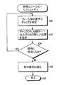
本発明の代替実施形態では、干渉のない受信に対して実際の時間スロットを与える必要がないことに注意されたい。その代わりに、所望の受信のための単純な時間枠をローカル・ノードに通知することが可能である。図14はこれを示す。前と同様に、バースト内の第1のパケットが、Probeパケットと呼ばれる。ノードAは、ノードBに通知するための最適な通知時間を決定する。これは、少なくとも1フレームの間隔をリスンし、(ノードBから送信された)アクティビティが低調な期間を識別することによって達成される。アクティビティが低調な間、ノードAが受信を行う最適な時間はProbeマップに封入される。この場合、一番最適な時間は、Probeが送信された後のTrである。ノードBがProbeを正常に受信すると、ノードBは、Probeパケットの受信を開始してからちょうどTr後にCTS(受信準備完了(Clear−to−Send))を送信することによって応答する。ノードBはさらに、ノードAの新しい干渉プロファイルを入力することによって、その表を更新する。このCTSメッセージは、データ・パケットをノードBに送信する最適時間(この場合はオフセットTcorrが一番最適な時間)を識別する別のマップと、Probeメッセージのために用いられる電力を増大させるかどうかを送信機に示す電力制御状態とを含む。これらのデータ・パケットは一定間隔Tfで送信される。さらに、CTSメッセージを受信した後のノードAは、その表にある、ノードBの干渉プロファイルを更新し、その電力制御情報を用いてデータ・メッセージを送信する。 Note that in alternative embodiments of the present invention, it is not necessary to provide actual time slots for interference free reception. Instead, it is possible to inform the local node of a simple time frame for the desired reception. FIG. 14 illustrates this. As before, the first packet in the burst is called the Probe packet. Node A determines the optimal notification time for notifying Node B. This is accomplished by listening for at least one frame interval and identifying periods of low activity (sent from Node B). While activity is low, the optimal time for node A to receive is enclosed in the Probe map. In this case, the most optimal time is Tr after the probe is transmitted. If Node B successfully receives the Probe, Node B responds by sending a CTS (Clear-to-Send) just Tr after starting to receive the Probe packet. Node B further updates its table by entering Node A's new interference profile. This CTS message increases the power used for the Probe message with another map identifying the optimal time to transmit a data packet to Node B (in this case the offset T corr is the most optimal time) Power control status indicating whether or not to the transmitter. These data packets are transmitted at regular intervals Tf. Further, node A after receiving the CTS message updates the interference profile of node B in the table, and transmits a data message using the power control information.
このプロトコルはさらに、ノードAおよびBが必要に応じてデュプレックス接続をセットアップすることを可能にし、さらに、その2つのノードによって観測されるチャネルの変化を補償する。このプロトコルは、SAMAの特徴である準周期的特性には違反しない。それは、そのデータ転送フェーズが基本的エチケットの場合と同等のままで、そのチャネルを用いる通信機器の集合体の全体性能を向上させるからである。 This protocol further allows nodes A and B to set up duplex connections as needed, and further compensates for channel changes observed by the two nodes. This protocol does not violate the quasi-periodic characteristics that are characteristic of SAMA. This is because the data transfer phase remains the same as in the case of basic etiquette, and the overall performance of the aggregate of communication devices using the channel is improved.
図15は、図14で示された通信システムの動作を示すフロー図である。前述のように、通信システム内の各ユニット/ノードは、同じ周波数帯で動作する。1つのノードから別のノードへの通信は、所定の時間の間に送信を行い、その後、所定の時間をおいて定期的に送信を続けることによって行われる。この論理フローは工程1501から始まる。工程1501では、ノードが干渉状態を監視し、その周波数帯で、干渉がほとんどあるいはまったくない状態で通信を受信できる時間帯を特定する。これは、受信機102からのRSSI 112を監視するプロセッサ130によって行われることが好ましい。具体的には、その周波数帯を監視して、その周波数帯内でアクティビティがほとんどあるいはまったく発生していない時間帯を特定する。工程1503で、ノードの干渉状態の表がプロセ
ッサ130によって作成され、RAM 131に格納され、その後、すべてのローカル・ノードに通知される。前述のように、この表は、干渉が発生する使用可能なスロットおよび/または干渉が発生しない使用可能なスロットの表を含むことが可能か、単に、受信に最適な時間帯および/または準最適な時間帯を識別することが可能である。
FIG. 15 is a flowchart showing the operation of the communication system shown in FIG. As described above, each unit / node in the communication system operates in the same frequency band. Communication from one node to another node is performed by performing transmission for a predetermined time, and then continuing transmission periodically after a predetermined time. This logic flow begins at
次に、工程1505で、ノードが(無線通信により)すべての近接ノードから、それらの干渉状態を示す表を受信する。前述のように、この干渉状態は、干渉が発生する使用可能なスロットおよび/または干渉が発生しない使用可能なスロットを含む表を含むことが可能か、受信に最適な時間帯および/または準最適な時間帯を含む表を含むことが可能である。また、近接ノードは、あらゆるタイプの通信機器(基地局、加入者ユニット、その他の通信用受信機または送信機など)を意味することが可能であることに注意されたい。工程1507で、ノードは、いずれかの近接ノードとの通信が必要かどうかを決定し、不要であれば、論理フローは単純に工程1507に戻る。一方、通信が必要であれば、論理フローは工程1509に進む。工程1509では、ノードが、その特定の近接ノードについて格納されている表にアクセスし、そのノードへの送信に最適な時間を決定する。この決定は、その近接ノードから受信した表を利用し、その近接ノードが受信を行う最適時間を決定することによって達成される。最後に、工程1511で、最適時間帯の間にProbeが近接ノードに送信され、アクセス手続きが前述のように行われ、情報が近接ノードに送信される。
Next, at step 1505, the node receives (by wireless communication) a table indicating their interference status from all neighboring nodes. As described above, this interference condition can include a table containing available slots where interference occurs and / or available slots where interference does not occur, or the optimal time zone and / or sub-optimal for reception It is possible to include a table containing various time zones. It should also be noted that a proximity node can mean any type of communication equipment (such as a base station, a subscriber unit, other communication receiver or transmitter). At
本発明を特定の実施形態に関して具体的に図示および説明してきたが、当業者であれば、本発明の趣旨および範囲を逸脱することなく、この実施形態の形状および細部を様々に変更することが可能であることを理解されよう。そのような変更は、添付の特許請求の範囲に含まれるものとする。 While the invention has been particularly shown and described with respect to a particular embodiment, those skilled in the art can make various changes in the shape and details of this embodiment without departing from the spirit and scope of the invention. It will be understood that it is possible. Such modifications are intended to fall within the scope of the appended claims.
Claims (10)
ノードが該周波数帯で干渉がほとんどあるいはまったくない状態で通信を受信することが可能な時間帯を含む干渉状態を決定するために、干渉を監視する工程と、
該ノードの干渉状態の表を作成する工程と、
該ノードの干渉状態を該通信システム内の近接ノードに通知する工程と、を含む方法。 A method for transmitting information in a communication system including a plurality of nodes that perform communication in the same frequency band,
Monitoring interference to determine an interference condition including a time period in which a node can receive communications with little or no interference in the frequency band;
Creating a table of interference states of the node;
And notifying neighboring nodes in the communication system of the interference state of the node.
該近接ノードへの送信を行う最適時間を該表から決定する工程と、
該決定された時間帯の間に情報を該近接ノードに送信する工程と、をさらに含む、請求項1に記載の方法。 Receiving from the neighboring node a second table that includes the interference state of the neighboring node;
Determining from the table an optimal time for transmission to the neighboring node;
The method of claim 1, further comprising transmitting information to the neighboring nodes during the determined time period.
前記周波数帯を監視して、前記周波数帯内でアクティビティがほとんどあるいはまったく発生していない時間帯を特定する工程、を含む請求項1に記載の方法。 Said step of monitoring interference comprises:
The method of claim 1, comprising monitoring the frequency band to identify a time period in which little or no activity occurs in the frequency band.
干渉が発生する使用可能なスロットおよび/または干渉が発生しない使用可能なスロットを含む表を作成する工程、を含む請求項1に記載の方法。 The step of creating the table includes:
The method of claim 1, comprising creating a table including available slots where interference occurs and / or available slots where interference does not occur.
受信に最適な時間帯および/または準最適な時間帯を含む表を作成する工程、を含む請求項1に記載の方法。 The step of creating the table includes:
The method according to claim 1, further comprising the step of creating a table including a time zone optimal for reception and / or a sub-optimal time zone.
該表を格納するメモリと、
通信システム内の近接ノードに該表を送信する送信機と、を含む装置。 A processor for monitoring interference in the frequency band and outputting a table including the interference state;
A memory for storing the table;
A transmitter that transmits the table to neighboring nodes in the communication system.
Applications Claiming Priority (2)
| Application Number | Priority Date | Filing Date | Title |
|---|---|---|---|
| US10/366,860 US7269152B2 (en) | 2003-02-14 | 2003-02-14 | Method and apparatus for transmitting information within a communication system |
| PCT/US2004/003407 WO2004075418A2 (en) | 2003-02-14 | 2004-02-05 | Method and apparatus for transmitting information within a communication system |
Publications (1)
| Publication Number | Publication Date |
|---|---|
| JP2006515497A true JP2006515497A (en) | 2006-05-25 |
Family
ID=32849828
Family Applications (1)
| Application Number | Title | Priority Date | Filing Date |
|---|---|---|---|
| JP2005518873A Pending JP2006515497A (en) | 2003-02-14 | 2004-02-05 | Method and apparatus for transmitting information in a communication system |
Country Status (7)
| Country | Link |
|---|---|
| US (1) | US7269152B2 (en) |
| EP (1) | EP1597603B1 (en) |
| JP (1) | JP2006515497A (en) |
| KR (1) | KR100772351B1 (en) |
| CN (1) | CN100527638C (en) |
| AT (1) | ATE536727T1 (en) |
| WO (1) | WO2004075418A2 (en) |
Cited By (6)
| Publication number | Priority date | Publication date | Assignee | Title |
|---|---|---|---|---|
| JP2009516418A (en) * | 2005-11-11 | 2009-04-16 | テレフオンアクチーボラゲット エル エム エリクソン(パブル) | Method and apparatus for limiting peer-to-peer communication interference |
| JP2009206933A (en) * | 2008-02-28 | 2009-09-10 | National Institute Of Information & Communication Technology | Cognitive radio communication network system and cognitive communication method |
| JP2010532622A (en) * | 2007-06-29 | 2010-10-07 | テレフオンアクチーボラゲット エル エム エリクソン(パブル) | Method for determining the relationship of subsequent time intervals with respect to a service request message from a user equipment |
| KR20180132720A (en) * | 2016-03-24 | 2018-12-12 | 프라운호퍼 게젤샤프트 쭈르 푀르데룽 데어 안겐반텐 포르슝 에. 베. | Telegram split transmission method for bi-directional network |
| JP2020532229A (en) * | 2017-08-29 | 2020-11-05 | テレフオンアクチーボラゲット エルエム エリクソン(パブル) | Co-scheduling of terminal devices |
| US10966244B2 (en) | 2015-11-12 | 2021-03-30 | Fujitsu Limited | Terminal device, base station device, wireless communication system, and wireless communication method |
Families Citing this family (53)
| Publication number | Priority date | Publication date | Assignee | Title |
|---|---|---|---|---|
| US20040171034A1 (en) * | 2002-05-03 | 2004-09-02 | Brian Agnew | Compositions and methods for detection and isolation of phosphorylated molecules |
| US7065144B2 (en) | 2003-08-27 | 2006-06-20 | Qualcomm Incorporated | Frequency-independent spatial processing for wideband MISO and MIMO systems |
| US7529247B2 (en) * | 2003-09-17 | 2009-05-05 | Rivulet Communications, Inc. | Empirical scheduling of network packets |
| US7468948B2 (en) | 2003-09-17 | 2008-12-23 | Steven A Rogers | Empirical scheduling of network packets using coarse and fine testing periods |
| US8284752B2 (en) | 2003-10-15 | 2012-10-09 | Qualcomm Incorporated | Method, apparatus, and system for medium access control |
| US8472473B2 (en) | 2003-10-15 | 2013-06-25 | Qualcomm Incorporated | Wireless LAN protocol stack |
| US9226308B2 (en) | 2003-10-15 | 2015-12-29 | Qualcomm Incorporated | Method, apparatus, and system for medium access control |
| US8483105B2 (en) | 2003-10-15 | 2013-07-09 | Qualcomm Incorporated | High speed media access control |
| US8462817B2 (en) | 2003-10-15 | 2013-06-11 | Qualcomm Incorporated | Method, apparatus, and system for multiplexing protocol data units |
| US8233462B2 (en) | 2003-10-15 | 2012-07-31 | Qualcomm Incorporated | High speed media access control and direct link protocol |
| US8842657B2 (en) | 2003-10-15 | 2014-09-23 | Qualcomm Incorporated | High speed media access control with legacy system interoperability |
| US7339923B2 (en) * | 2003-10-31 | 2008-03-04 | Rivulet Communications, Inc. | Endpoint packet scheduling system |
| US7508813B2 (en) * | 2003-11-25 | 2009-03-24 | Rivulet Communications | Local area network contention avoidance |
| US7818018B2 (en) * | 2004-01-29 | 2010-10-19 | Qualcomm Incorporated | Distributed hierarchical scheduling in an AD hoc network |
| US8903440B2 (en) | 2004-01-29 | 2014-12-02 | Qualcomm Incorporated | Distributed hierarchical scheduling in an ad hoc network |
| US8315271B2 (en) | 2004-03-26 | 2012-11-20 | Qualcomm Incorporated | Method and apparatus for an ad-hoc wireless communications system |
| US7564814B2 (en) | 2004-05-07 | 2009-07-21 | Qualcomm, Incorporated | Transmission mode and rate selection for a wireless communication system |
| US8401018B2 (en) | 2004-06-02 | 2013-03-19 | Qualcomm Incorporated | Method and apparatus for scheduling in a wireless network |
| US7453885B2 (en) * | 2004-10-13 | 2008-11-18 | Rivulet Communications, Inc. | Network connection device |
| US8848574B2 (en) | 2005-03-15 | 2014-09-30 | Qualcomm Incorporated | Interference control in a wireless communication system |
| US8942639B2 (en) * | 2005-03-15 | 2015-01-27 | Qualcomm Incorporated | Interference control in a wireless communication system |
| JP4728036B2 (en) * | 2005-04-26 | 2011-07-20 | 株式会社日立製作所 | Wireless communication system |
| JP4569374B2 (en) * | 2005-05-10 | 2010-10-27 | 富士通株式会社 | Wireless communication apparatus and wireless communication method |
| US8600336B2 (en) | 2005-09-12 | 2013-12-03 | Qualcomm Incorporated | Scheduling with reverse direction grant in wireless communication systems |
| US8667116B2 (en) * | 2005-09-30 | 2014-03-04 | Robert Bosch Gmbh | Method and system for providing reliable communication with redundancy for energy constrained wireless systems |
| US7613146B2 (en) * | 2005-09-30 | 2009-11-03 | Robert Bosch Gmbh | Method and system for reliable data transmission in wireless networks |
| WO2007051140A2 (en) * | 2005-10-26 | 2007-05-03 | Qualcomm Incorporated | Flexible medium access control (mac) method for ad hoc wireless networks |
| JP5430938B2 (en) | 2005-10-27 | 2014-03-05 | クゥアルコム・インコーポレイテッド | Method and apparatus for estimating reverse link loading in a wireless communication system |
| US8345647B2 (en) * | 2005-11-04 | 2013-01-01 | Nokia Corporation | Flexible multicast and/or broadcast listening intervals |
| US7730382B2 (en) * | 2005-12-02 | 2010-06-01 | Beceem Communications Inc. | Method and system for managing memory in a communication system using hybrid automatic repeat request (HARQ) |
| US9232537B2 (en) * | 2006-02-07 | 2016-01-05 | Qualcomm Incorporated | Apparatus and method for fast access in a wireless communication system |
| US9674869B2 (en) * | 2006-03-20 | 2017-06-06 | Qualcomm Incorporated | Apparatus and method for fast access in a wireless communication system |
| US20080117849A1 (en) * | 2006-09-08 | 2008-05-22 | Qualcomm Incorporated | Method and apparatus for interaction of fast other sector interference (osi) with slow osi |
| US8670777B2 (en) | 2006-09-08 | 2014-03-11 | Qualcomm Incorporated | Method and apparatus for fast other sector interference (OSI) adjustment |
| US8031795B2 (en) * | 2006-12-12 | 2011-10-04 | Hong Kong Applied Science And Technology Research Institute Co., Ltd. | Pre-processing systems and methods for MIMO antenna systems |
| US8295216B2 (en) * | 2006-12-21 | 2012-10-23 | Nokia Corporation | Broadcast and multicast transmission techniques for powersave devices in wireless networks |
| US20080186842A1 (en) * | 2007-01-31 | 2008-08-07 | Ntt Docomo. Inc. | Detect-and-multiplex technique for spectrum sharing |
| US8169957B2 (en) * | 2007-02-05 | 2012-05-01 | Qualcomm Incorporated | Flexible DTX and DRX in a wireless communication system |
| JP5147869B2 (en) * | 2007-03-22 | 2013-02-20 | テレフオンアクチーボラゲット エル エム エリクソン(パブル) | Method and apparatus in communication system |
| TWI398178B (en) | 2008-09-25 | 2013-06-01 | Skyphy Networks Ltd | Multi-hop wireless systems having noise reduction and bandwidth expansion capabilities and the methods of the same |
| CN101828419A (en) * | 2008-09-25 | 2010-09-08 | 智格网信息科技(成都)有限公司 | Method and system for resisting interference and enlarging network capability in wireless multi-hop networks |
| CN101729224A (en) * | 2008-10-20 | 2010-06-09 | 富士通株式会社 | Transmission data generating device and receiving machine |
| US8693336B2 (en) * | 2008-11-10 | 2014-04-08 | Qualcomm Incorporated | Communications decision methods and apparatus |
| US8520524B2 (en) * | 2008-11-10 | 2013-08-27 | Qualcomm Incorporated | Methods and apparatus for making transmitter and/or receiver communications decisions |
| EP2401884B1 (en) * | 2009-02-24 | 2017-07-19 | Nokia Technologies Oy | Time-hopping for near-far interference mitigation in device-to-device communications |
| US8073014B2 (en) * | 2009-03-02 | 2011-12-06 | Motorola Mobility, Inc. | Method and apparatus for synchronizing nodes |
| JP5304496B2 (en) * | 2009-07-09 | 2013-10-02 | 株式会社デンソー | Communication node |
| US8781400B2 (en) * | 2011-06-30 | 2014-07-15 | Telefonaktiebolaget L M Ericsson (Publ) | Method and apparatus for reducing co-channel interference |
| US20140118222A1 (en) * | 2012-10-30 | 2014-05-01 | Cloudcar, Inc. | Projection of content to external display devices |
| US10898076B2 (en) | 2013-09-30 | 2021-01-26 | The Research Foundation For The State University Of New York | Transmission and medium access control techniques for ultrasonic communications in the body |
| US9591509B2 (en) * | 2014-04-10 | 2017-03-07 | Qualcomm Incorporated | Congestion control scheme |
| DE102016205054A1 (en) * | 2016-03-24 | 2017-09-28 | Fraunhofer-Gesellschaft zur Förderung der angewandten Forschung e.V. | TELEGRAM MESSAGE TRANSMISSION PROCEDURE FOR BIDIRECTIONAL NETWORKS |
| US10114741B1 (en) | 2016-11-23 | 2018-10-30 | Levyx, Inc. | Data traffic reservation systems and methods |
Family Cites Families (22)
| Publication number | Priority date | Publication date | Assignee | Title |
|---|---|---|---|---|
| US3911432A (en) * | 1974-04-17 | 1975-10-07 | Us Navy | Technique for eliminating mutual interference between adjacent asynchronous radar systems |
| JPH02312492A (en) * | 1989-05-29 | 1990-12-27 | Nec Corp | Channel assignment method in mobile communication system and learning system for base station arrangement information |
| US5355522A (en) * | 1992-06-26 | 1994-10-11 | Motorola, Inc. | Frequency selection method and apparatus |
| US5471650A (en) * | 1993-01-07 | 1995-11-28 | Northern Telecom Limited | Radio link parameter control in wireless personal communications system |
| DE4325190A1 (en) * | 1993-07-27 | 1995-02-02 | Siemens Ag | Radio system with frequency optimization |
| US5412658A (en) * | 1993-10-22 | 1995-05-02 | Bell Communications Research, Inc. | Beacon detection method and apparatus for sharing spectrum between wireless communications systems and fixed microwave systems |
| US6088590A (en) * | 1993-11-01 | 2000-07-11 | Omnipoint Corporation | Method and system for mobile controlled handoff and link maintenance in spread spectrum communication |
| CN1141102A (en) * | 1994-12-19 | 1997-01-22 | 摩托罗拉公司 | Method and apparatus for mitigating interference in a communication system |
| US6496700B1 (en) * | 1996-04-04 | 2002-12-17 | At&T Wireless Services, Inc. | Method for determining organization parameters in a wireless communication system |
| US5987018A (en) | 1996-05-02 | 1999-11-16 | Motorola, Inc | Radio unit, method of communicating between radio units over a communications channel and method of preparing a sequence of data cells for transmission over a radio channel |
| US6128327A (en) * | 1998-01-29 | 2000-10-03 | Ericsson Inc. | Frequency hopping |
| US6895245B2 (en) * | 1998-03-06 | 2005-05-17 | Telefonaktiebolaget Lm Ericssion(Publ) | Telecommunications interexchange measurement transfer |
| US6480721B1 (en) * | 1998-07-10 | 2002-11-12 | Siemens Information And Communication Mobile Llc | Method and system for avoiding bad frequency subsets in a frequency hopping cordless telephone system |
| JP3397328B2 (en) * | 1998-09-30 | 2003-04-14 | 三菱電機株式会社 | TDMA wireless communication system, base station apparatus and subscriber station apparatus performing wireless communication |
| US6272353B1 (en) * | 1999-08-20 | 2001-08-07 | Siemens Information And Communication Mobile Llc. | Method and system for mobile communications |
| JP3621310B2 (en) * | 1999-10-07 | 2005-02-16 | 松下電器産業株式会社 | Wireless communication apparatus and transmission power control method |
| US7006453B1 (en) * | 2000-03-14 | 2006-02-28 | Lucent Technologies Inc. | Location based routing for mobile ad-hoc networks |
| US6639541B1 (en) * | 2000-08-29 | 2003-10-28 | The United States Of America As Represented By The Secretary Of The Navy | Device and method for detecting, measuring, and reporting low-level interference at a receiver |
| US6888805B2 (en) * | 2001-03-23 | 2005-05-03 | Qualcomm Incorporated | Time multiplexed transmission scheme for a spread spectrum communication system |
| US7079812B2 (en) * | 2002-05-16 | 2006-07-18 | Cognio, Inc. | Systems and methods for interference mitigation with respect to periodic interferers in short-range wireless applications |
| US6941110B2 (en) * | 2003-01-14 | 2005-09-06 | Cognio, Inc. | Mitigating interference with frequency hopping signals by deriving future hop frequencies |
| US8149707B2 (en) * | 2003-02-12 | 2012-04-03 | Rockstar Bidco, LP | Minimization of radio resource usage in multi-hop networks with multiple routings |
-
2003
- 2003-02-14 US US10/366,860 patent/US7269152B2/en not_active Expired - Lifetime
-
2004
- 2004-02-05 KR KR1020057014924A patent/KR100772351B1/en not_active IP Right Cessation
- 2004-02-05 JP JP2005518873A patent/JP2006515497A/en active Pending
- 2004-02-05 WO PCT/US2004/003407 patent/WO2004075418A2/en active Application Filing
- 2004-02-05 AT AT04708633T patent/ATE536727T1/en active
- 2004-02-05 EP EP04708633A patent/EP1597603B1/en not_active Expired - Lifetime
- 2004-02-05 CN CNB200480004255XA patent/CN100527638C/en not_active Expired - Lifetime
Cited By (11)
| Publication number | Priority date | Publication date | Assignee | Title |
|---|---|---|---|---|
| JP2009516418A (en) * | 2005-11-11 | 2009-04-16 | テレフオンアクチーボラゲット エル エム エリクソン(パブル) | Method and apparatus for limiting peer-to-peer communication interference |
| JP4933558B2 (en) * | 2005-11-11 | 2012-05-16 | テレフオンアクチーボラゲット エル エム エリクソン(パブル) | Method and apparatus for limiting peer-to-peer communication interference |
| JP2010532622A (en) * | 2007-06-29 | 2010-10-07 | テレフオンアクチーボラゲット エル エム エリクソン(パブル) | Method for determining the relationship of subsequent time intervals with respect to a service request message from a user equipment |
| US8428631B2 (en) | 2007-06-29 | 2013-04-23 | Telefonaktiebolaget Lm Ericsson (Publ) | Method for determining a subsequent time interval relationship, for service request messages, from a user equipment |
| JP2009206933A (en) * | 2008-02-28 | 2009-09-10 | National Institute Of Information & Communication Technology | Cognitive radio communication network system and cognitive communication method |
| US10966244B2 (en) | 2015-11-12 | 2021-03-30 | Fujitsu Limited | Terminal device, base station device, wireless communication system, and wireless communication method |
| US11856601B2 (en) | 2015-11-12 | 2023-12-26 | Fujitsu Limited | Terminal device, base station device, wireless communication system, and wireless communication method for allocating random access resources in an unlicensed band |
| KR20180132720A (en) * | 2016-03-24 | 2018-12-12 | 프라운호퍼 게젤샤프트 쭈르 푀르데룽 데어 안겐반텐 포르슝 에. 베. | Telegram split transmission method for bi-directional network |
| JP2019514253A (en) * | 2016-03-24 | 2019-05-30 | フラウンホファー ゲセルシャフト ツール フェールデルンク ダー アンゲヴァンテン フォルシュンク エー.ファオ. | Method of telegram division transmission by bidirectional network |
| KR102244593B1 (en) | 2016-03-24 | 2021-04-27 | 프라운호퍼 게젤샤프트 쭈르 푀르데룽 데어 안겐반텐 포르슝 에. 베. | Telegram segmentation transmission method for bidirectional networks |
| JP2020532229A (en) * | 2017-08-29 | 2020-11-05 | テレフオンアクチーボラゲット エルエム エリクソン(パブル) | Co-scheduling of terminal devices |
Also Published As
| Publication number | Publication date |
|---|---|
| WO2004075418A3 (en) | 2005-02-24 |
| KR100772351B1 (en) | 2007-11-02 |
| US7269152B2 (en) | 2007-09-11 |
| KR20050100398A (en) | 2005-10-18 |
| CN1751243A (en) | 2006-03-22 |
| EP1597603A4 (en) | 2009-06-03 |
| CN100527638C (en) | 2009-08-12 |
| US20040160916A1 (en) | 2004-08-19 |
| EP1597603A2 (en) | 2005-11-23 |
| EP1597603B1 (en) | 2011-12-07 |
| ATE536727T1 (en) | 2011-12-15 |
| WO2004075418A2 (en) | 2004-09-02 |
Similar Documents
| Publication | Publication Date | Title |
|---|---|---|
| JP2006515497A (en) | Method and apparatus for transmitting information in a communication system | |
| US5987018A (en) | Radio unit, method of communicating between radio units over a communications channel and method of preparing a sequence of data cells for transmission over a radio channel | |
| JP3464453B2 (en) | Data transmission method | |
| EP2375655B1 (en) | Adaptive use of a transmit opportunity | |
| JP4095618B2 (en) | Packet format | |
| US6744766B2 (en) | Hybrid ARQ for a wireless Ad-Hoc network and a method for using the same | |
| US6996100B1 (en) | Method and system for medium access on a radio channel | |
| US20070064668A1 (en) | Method and apparatus for improving transmission delay of status report in a wireless communications system | |
| CN103580773A (en) | Method and device for transmitting data frame | |
| US6553032B1 (en) | Packeting timeout spoofing in a wireless data communications network | |
| KR100970543B1 (en) | Arq mac for ad-hoc communication networks and a method for using the same | |
| US8630168B2 (en) | Adaptive use of a transmit opportunity | |
| WO2006048969A1 (en) | Transmitter apparatus | |
| JP3476985B2 (en) | Packet communication system and packet communication control method | |
| US20050066255A1 (en) | Status report missing detection in a communication system | |
| US20070195813A1 (en) | Multicast packet transmitting method of wireless network | |
| Villalon et al. | ARSM: a cross-layer auto rate selection multicast mechanism for multi-rate wireless LANs | |
| KR100660055B1 (en) | Method for transmitting packet in wireless telecommunication terminal | |
| JP4163643B2 (en) | Wireless communication system, wireless base station, wireless terminal, and wireless communication method | |
| Zorzi et al. | The role of error correlations in the design of protocols for packet switched services | |
| Borgonovo et al. | MAC for WATM air interface: impact of error control schemes on protocol design | |
| Li et al. | Performance of the radio link protocol of hiperlan/2 | |
| KR101376460B1 (en) | Apparatus and method for transmitting packet in a communication system | |
| Tykhomyrov et al. | Analysis and performance evaluation of the IEEE 802.16 ARQ mechanism | |
| JP2005529518A (en) | Hybrid ARQ for wireless ad hoc networks and its usage |
Legal Events
| Date | Code | Title | Description |
|---|---|---|---|
| A977 | Report on retrieval |
Free format text: JAPANESE INTERMEDIATE CODE: A971007 Effective date: 20080227 |
|
| A131 | Notification of reasons for refusal |
Free format text: JAPANESE INTERMEDIATE CODE: A131 Effective date: 20080624 |
|
| A601 | Written request for extension of time |
Free format text: JAPANESE INTERMEDIATE CODE: A601 Effective date: 20080924 |
|
| A602 | Written permission of extension of time |
Free format text: JAPANESE INTERMEDIATE CODE: A602 Effective date: 20081001 |
|
| A521 | Request for written amendment filed |
Free format text: JAPANESE INTERMEDIATE CODE: A523 Effective date: 20081020 |
|
| A02 | Decision of refusal |
Free format text: JAPANESE INTERMEDIATE CODE: A02 Effective date: 20081224 |