JP2006509609A - Computer-aided hip replacement surgery - Google Patents
Computer-aided hip replacement surgery Download PDFInfo
- Publication number
- JP2006509609A JP2006509609A JP2005500011A JP2005500011A JP2006509609A JP 2006509609 A JP2006509609 A JP 2006509609A JP 2005500011 A JP2005500011 A JP 2005500011A JP 2005500011 A JP2005500011 A JP 2005500011A JP 2006509609 A JP2006509609 A JP 2006509609A
- Authority
- JP
- Japan
- Prior art keywords
- implant
- femur
- orientation
- femoral
- tracking
- Prior art date
- Legal status (The legal status is an assumption and is not a legal conclusion. Google has not performed a legal analysis and makes no representation as to the accuracy of the status listed.)
- Pending
Links
Images


Classifications
-
- A—HUMAN NECESSITIES
- A61—MEDICAL OR VETERINARY SCIENCE; HYGIENE
- A61B—DIAGNOSIS; SURGERY; IDENTIFICATION
- A61B34/00—Computer-aided surgery; Manipulators or robots specially adapted for use in surgery
- A61B34/10—Computer-aided planning, simulation or modelling of surgical operations
-
- A—HUMAN NECESSITIES
- A61—MEDICAL OR VETERINARY SCIENCE; HYGIENE
- A61B—DIAGNOSIS; SURGERY; IDENTIFICATION
- A61B17/00—Surgical instruments, devices or methods, e.g. tourniquets
- A61B17/14—Surgical saws ; Accessories therefor
- A61B17/15—Guides therefor
-
- A—HUMAN NECESSITIES
- A61—MEDICAL OR VETERINARY SCIENCE; HYGIENE
- A61B—DIAGNOSIS; SURGERY; IDENTIFICATION
- A61B17/00—Surgical instruments, devices or methods, e.g. tourniquets
- A61B17/16—Bone cutting, breaking or removal means other than saws, e.g. Osteoclasts; Drills or chisels for bones; Trepans
- A61B17/1662—Bone cutting, breaking or removal means other than saws, e.g. Osteoclasts; Drills or chisels for bones; Trepans for particular parts of the body
- A61B17/1664—Bone cutting, breaking or removal means other than saws, e.g. Osteoclasts; Drills or chisels for bones; Trepans for particular parts of the body for the hip
- A61B17/1666—Bone cutting, breaking or removal means other than saws, e.g. Osteoclasts; Drills or chisels for bones; Trepans for particular parts of the body for the hip for the acetabulum
-
- A—HUMAN NECESSITIES
- A61—MEDICAL OR VETERINARY SCIENCE; HYGIENE
- A61B—DIAGNOSIS; SURGERY; IDENTIFICATION
- A61B17/00—Surgical instruments, devices or methods, e.g. tourniquets
- A61B17/16—Bone cutting, breaking or removal means other than saws, e.g. Osteoclasts; Drills or chisels for bones; Trepans
- A61B17/17—Guides or aligning means for drills, mills, pins or wires
- A61B17/1703—Guides or aligning means for drills, mills, pins or wires using imaging means, e.g. by X-rays
-
- A—HUMAN NECESSITIES
- A61—MEDICAL OR VETERINARY SCIENCE; HYGIENE
- A61B—DIAGNOSIS; SURGERY; IDENTIFICATION
- A61B17/00—Surgical instruments, devices or methods, e.g. tourniquets
- A61B17/16—Bone cutting, breaking or removal means other than saws, e.g. Osteoclasts; Drills or chisels for bones; Trepans
- A61B17/17—Guides or aligning means for drills, mills, pins or wires
- A61B17/1717—Guides or aligning means for drills, mills, pins or wires for applying intramedullary nails or pins
-
- A—HUMAN NECESSITIES
- A61—MEDICAL OR VETERINARY SCIENCE; HYGIENE
- A61B—DIAGNOSIS; SURGERY; IDENTIFICATION
- A61B17/00—Surgical instruments, devices or methods, e.g. tourniquets
- A61B17/16—Bone cutting, breaking or removal means other than saws, e.g. Osteoclasts; Drills or chisels for bones; Trepans
- A61B17/17—Guides or aligning means for drills, mills, pins or wires
- A61B17/1739—Guides or aligning means for drills, mills, pins or wires specially adapted for particular parts of the body
- A61B17/1742—Guides or aligning means for drills, mills, pins or wires specially adapted for particular parts of the body for the hip
- A61B17/1746—Guides or aligning means for drills, mills, pins or wires specially adapted for particular parts of the body for the hip for the acetabulum
-
- A—HUMAN NECESSITIES
- A61—MEDICAL OR VETERINARY SCIENCE; HYGIENE
- A61B—DIAGNOSIS; SURGERY; IDENTIFICATION
- A61B17/00—Surgical instruments, devices or methods, e.g. tourniquets
- A61B17/16—Bone cutting, breaking or removal means other than saws, e.g. Osteoclasts; Drills or chisels for bones; Trepans
- A61B17/17—Guides or aligning means for drills, mills, pins or wires
- A61B17/1739—Guides or aligning means for drills, mills, pins or wires specially adapted for particular parts of the body
- A61B17/1742—Guides or aligning means for drills, mills, pins or wires specially adapted for particular parts of the body for the hip
- A61B17/175—Guides or aligning means for drills, mills, pins or wires specially adapted for particular parts of the body for the hip for preparing the femur for hip prosthesis insertion
-
- A—HUMAN NECESSITIES
- A61—MEDICAL OR VETERINARY SCIENCE; HYGIENE
- A61B—DIAGNOSIS; SURGERY; IDENTIFICATION
- A61B34/00—Computer-aided surgery; Manipulators or robots specially adapted for use in surgery
- A61B34/20—Surgical navigation systems; Devices for tracking or guiding surgical instruments, e.g. for frameless stereotaxis
-
- A—HUMAN NECESSITIES
- A61—MEDICAL OR VETERINARY SCIENCE; HYGIENE
- A61B—DIAGNOSIS; SURGERY; IDENTIFICATION
- A61B5/00—Measuring for diagnostic purposes; Identification of persons
- A61B5/06—Devices, other than using radiation, for detecting or locating foreign bodies ; determining position of probes within or on the body of the patient
- A61B5/061—Determining position of a probe within the body employing means separate from the probe, e.g. sensing internal probe position employing impedance electrodes on the surface of the body
- A61B5/064—Determining position of a probe within the body employing means separate from the probe, e.g. sensing internal probe position employing impedance electrodes on the surface of the body using markers
-
- A—HUMAN NECESSITIES
- A61—MEDICAL OR VETERINARY SCIENCE; HYGIENE
- A61B—DIAGNOSIS; SURGERY; IDENTIFICATION
- A61B5/00—Measuring for diagnostic purposes; Identification of persons
- A61B5/103—Detecting, measuring or recording devices for testing the shape, pattern, colour, size or movement of the body or parts thereof, for diagnostic purposes
-
- A—HUMAN NECESSITIES
- A61—MEDICAL OR VETERINARY SCIENCE; HYGIENE
- A61B—DIAGNOSIS; SURGERY; IDENTIFICATION
- A61B90/00—Instruments, implements or accessories specially adapted for surgery or diagnosis and not covered by any of the groups A61B1/00 - A61B50/00, e.g. for luxation treatment or for protecting wound edges
- A61B90/36—Image-producing devices or illumination devices not otherwise provided for
-
- A—HUMAN NECESSITIES
- A61—MEDICAL OR VETERINARY SCIENCE; HYGIENE
- A61F—FILTERS IMPLANTABLE INTO BLOOD VESSELS; PROSTHESES; DEVICES PROVIDING PATENCY TO, OR PREVENTING COLLAPSING OF, TUBULAR STRUCTURES OF THE BODY, e.g. STENTS; ORTHOPAEDIC, NURSING OR CONTRACEPTIVE DEVICES; FOMENTATION; TREATMENT OR PROTECTION OF EYES OR EARS; BANDAGES, DRESSINGS OR ABSORBENT PADS; FIRST-AID KITS
- A61F2/00—Filters implantable into blood vessels; Prostheses, i.e. artificial substitutes or replacements for parts of the body; Appliances for connecting them with the body; Devices providing patency to, or preventing collapsing of, tubular structures of the body, e.g. stents
- A61F2/02—Prostheses implantable into the body
- A61F2/30—Joints
- A61F2/32—Joints for the hip
-
- A—HUMAN NECESSITIES
- A61—MEDICAL OR VETERINARY SCIENCE; HYGIENE
- A61F—FILTERS IMPLANTABLE INTO BLOOD VESSELS; PROSTHESES; DEVICES PROVIDING PATENCY TO, OR PREVENTING COLLAPSING OF, TUBULAR STRUCTURES OF THE BODY, e.g. STENTS; ORTHOPAEDIC, NURSING OR CONTRACEPTIVE DEVICES; FOMENTATION; TREATMENT OR PROTECTION OF EYES OR EARS; BANDAGES, DRESSINGS OR ABSORBENT PADS; FIRST-AID KITS
- A61F2/00—Filters implantable into blood vessels; Prostheses, i.e. artificial substitutes or replacements for parts of the body; Appliances for connecting them with the body; Devices providing patency to, or preventing collapsing of, tubular structures of the body, e.g. stents
- A61F2/02—Prostheses implantable into the body
- A61F2/30—Joints
- A61F2/46—Special tools or methods for implanting or extracting artificial joints, accessories, bone grafts or substitutes, or particular adaptations therefor
- A61F2/4657—Measuring instruments used for implanting artificial joints
-
- G—PHYSICS
- G09—EDUCATION; CRYPTOGRAPHY; DISPLAY; ADVERTISING; SEALS
- G09B—EDUCATIONAL OR DEMONSTRATION APPLIANCES; APPLIANCES FOR TEACHING, OR COMMUNICATING WITH, THE BLIND, DEAF OR MUTE; MODELS; PLANETARIA; GLOBES; MAPS; DIAGRAMS
- G09B23/00—Models for scientific, medical, or mathematical purposes, e.g. full-sized devices for demonstration purposes
- G09B23/28—Models for scientific, medical, or mathematical purposes, e.g. full-sized devices for demonstration purposes for medicine
- G09B23/30—Anatomical models
-
- A—HUMAN NECESSITIES
- A61—MEDICAL OR VETERINARY SCIENCE; HYGIENE
- A61B—DIAGNOSIS; SURGERY; IDENTIFICATION
- A61B17/00—Surgical instruments, devices or methods, e.g. tourniquets
- A61B17/16—Bone cutting, breaking or removal means other than saws, e.g. Osteoclasts; Drills or chisels for bones; Trepans
- A61B17/17—Guides or aligning means for drills, mills, pins or wires
- A61B17/1735—Guides or aligning means for drills, mills, pins or wires for rasps or chisels
-
- A—HUMAN NECESSITIES
- A61—MEDICAL OR VETERINARY SCIENCE; HYGIENE
- A61B—DIAGNOSIS; SURGERY; IDENTIFICATION
- A61B34/00—Computer-aided surgery; Manipulators or robots specially adapted for use in surgery
- A61B34/10—Computer-aided planning, simulation or modelling of surgical operations
- A61B2034/101—Computer-aided simulation of surgical operations
- A61B2034/102—Modelling of surgical devices, implants or prosthesis
- A61B2034/104—Modelling the effect of the tool, e.g. the effect of an implanted prosthesis or for predicting the effect of ablation or burring
-
- A—HUMAN NECESSITIES
- A61—MEDICAL OR VETERINARY SCIENCE; HYGIENE
- A61B—DIAGNOSIS; SURGERY; IDENTIFICATION
- A61B34/00—Computer-aided surgery; Manipulators or robots specially adapted for use in surgery
- A61B34/10—Computer-aided planning, simulation or modelling of surgical operations
- A61B2034/101—Computer-aided simulation of surgical operations
- A61B2034/105—Modelling of the patient, e.g. for ligaments or bones
-
- A—HUMAN NECESSITIES
- A61—MEDICAL OR VETERINARY SCIENCE; HYGIENE
- A61B—DIAGNOSIS; SURGERY; IDENTIFICATION
- A61B34/00—Computer-aided surgery; Manipulators or robots specially adapted for use in surgery
- A61B34/10—Computer-aided planning, simulation or modelling of surgical operations
- A61B2034/107—Visualisation of planned trajectories or target regions
-
- A—HUMAN NECESSITIES
- A61—MEDICAL OR VETERINARY SCIENCE; HYGIENE
- A61B—DIAGNOSIS; SURGERY; IDENTIFICATION
- A61B34/00—Computer-aided surgery; Manipulators or robots specially adapted for use in surgery
- A61B34/10—Computer-aided planning, simulation or modelling of surgical operations
- A61B2034/108—Computer aided selection or customisation of medical implants or cutting guides
-
- A—HUMAN NECESSITIES
- A61—MEDICAL OR VETERINARY SCIENCE; HYGIENE
- A61B—DIAGNOSIS; SURGERY; IDENTIFICATION
- A61B34/00—Computer-aided surgery; Manipulators or robots specially adapted for use in surgery
- A61B34/20—Surgical navigation systems; Devices for tracking or guiding surgical instruments, e.g. for frameless stereotaxis
- A61B2034/2046—Tracking techniques
- A61B2034/2055—Optical tracking systems
-
- A—HUMAN NECESSITIES
- A61—MEDICAL OR VETERINARY SCIENCE; HYGIENE
- A61B—DIAGNOSIS; SURGERY; IDENTIFICATION
- A61B34/00—Computer-aided surgery; Manipulators or robots specially adapted for use in surgery
- A61B34/20—Surgical navigation systems; Devices for tracking or guiding surgical instruments, e.g. for frameless stereotaxis
- A61B2034/2068—Surgical navigation systems; Devices for tracking or guiding surgical instruments, e.g. for frameless stereotaxis using pointers, e.g. pointers having reference marks for determining coordinates of body points
-
- A—HUMAN NECESSITIES
- A61—MEDICAL OR VETERINARY SCIENCE; HYGIENE
- A61B—DIAGNOSIS; SURGERY; IDENTIFICATION
- A61B34/00—Computer-aided surgery; Manipulators or robots specially adapted for use in surgery
- A61B34/20—Surgical navigation systems; Devices for tracking or guiding surgical instruments, e.g. for frameless stereotaxis
- A61B2034/2072—Reference field transducer attached to an instrument or patient
-
- A—HUMAN NECESSITIES
- A61—MEDICAL OR VETERINARY SCIENCE; HYGIENE
- A61B—DIAGNOSIS; SURGERY; IDENTIFICATION
- A61B34/00—Computer-aided surgery; Manipulators or robots specially adapted for use in surgery
- A61B34/25—User interfaces for surgical systems
- A61B2034/252—User interfaces for surgical systems indicating steps of a surgical procedure
-
- A—HUMAN NECESSITIES
- A61—MEDICAL OR VETERINARY SCIENCE; HYGIENE
- A61B—DIAGNOSIS; SURGERY; IDENTIFICATION
- A61B34/00—Computer-aided surgery; Manipulators or robots specially adapted for use in surgery
- A61B34/25—User interfaces for surgical systems
- A61B2034/256—User interfaces for surgical systems having a database of accessory information, e.g. including context sensitive help or scientific articles
-
- A—HUMAN NECESSITIES
- A61—MEDICAL OR VETERINARY SCIENCE; HYGIENE
- A61B—DIAGNOSIS; SURGERY; IDENTIFICATION
- A61B90/00—Instruments, implements or accessories specially adapted for surgery or diagnosis and not covered by any of the groups A61B1/00 - A61B50/00, e.g. for luxation treatment or for protecting wound edges
- A61B90/06—Measuring instruments not otherwise provided for
- A61B2090/062—Measuring instruments not otherwise provided for penetration depth
-
- A—HUMAN NECESSITIES
- A61—MEDICAL OR VETERINARY SCIENCE; HYGIENE
- A61B—DIAGNOSIS; SURGERY; IDENTIFICATION
- A61B90/00—Instruments, implements or accessories specially adapted for surgery or diagnosis and not covered by any of the groups A61B1/00 - A61B50/00, e.g. for luxation treatment or for protecting wound edges
- A61B90/36—Image-producing devices or illumination devices not otherwise provided for
- A61B2090/363—Use of fiducial points
-
- A—HUMAN NECESSITIES
- A61—MEDICAL OR VETERINARY SCIENCE; HYGIENE
- A61B—DIAGNOSIS; SURGERY; IDENTIFICATION
- A61B90/00—Instruments, implements or accessories specially adapted for surgery or diagnosis and not covered by any of the groups A61B1/00 - A61B50/00, e.g. for luxation treatment or for protecting wound edges
- A61B90/39—Markers, e.g. radio-opaque or breast lesions markers
- A61B2090/3983—Reference marker arrangements for use with image guided surgery
-
- A—HUMAN NECESSITIES
- A61—MEDICAL OR VETERINARY SCIENCE; HYGIENE
- A61B—DIAGNOSIS; SURGERY; IDENTIFICATION
- A61B34/00—Computer-aided surgery; Manipulators or robots specially adapted for use in surgery
- A61B34/25—User interfaces for surgical systems
-
- A—HUMAN NECESSITIES
- A61—MEDICAL OR VETERINARY SCIENCE; HYGIENE
- A61B—DIAGNOSIS; SURGERY; IDENTIFICATION
- A61B34/00—Computer-aided surgery; Manipulators or robots specially adapted for use in surgery
- A61B34/70—Manipulators specially adapted for use in surgery
-
- A—HUMAN NECESSITIES
- A61—MEDICAL OR VETERINARY SCIENCE; HYGIENE
- A61B—DIAGNOSIS; SURGERY; IDENTIFICATION
- A61B5/00—Measuring for diagnostic purposes; Identification of persons
- A61B5/45—For evaluating or diagnosing the musculoskeletal system or teeth
- A61B5/4528—Joints
-
- A—HUMAN NECESSITIES
- A61—MEDICAL OR VETERINARY SCIENCE; HYGIENE
- A61B—DIAGNOSIS; SURGERY; IDENTIFICATION
- A61B5/00—Measuring for diagnostic purposes; Identification of persons
- A61B5/68—Arrangements of detecting, measuring or recording means, e.g. sensors, in relation to patient
- A61B5/6846—Arrangements of detecting, measuring or recording means, e.g. sensors, in relation to patient specially adapted to be brought in contact with an internal body part, i.e. invasive
- A61B5/6867—Arrangements of detecting, measuring or recording means, e.g. sensors, in relation to patient specially adapted to be brought in contact with an internal body part, i.e. invasive specially adapted to be attached or implanted in a specific body part
- A61B5/6878—Bone
-
- A—HUMAN NECESSITIES
- A61—MEDICAL OR VETERINARY SCIENCE; HYGIENE
- A61F—FILTERS IMPLANTABLE INTO BLOOD VESSELS; PROSTHESES; DEVICES PROVIDING PATENCY TO, OR PREVENTING COLLAPSING OF, TUBULAR STRUCTURES OF THE BODY, e.g. STENTS; ORTHOPAEDIC, NURSING OR CONTRACEPTIVE DEVICES; FOMENTATION; TREATMENT OR PROTECTION OF EYES OR EARS; BANDAGES, DRESSINGS OR ABSORBENT PADS; FIRST-AID KITS
- A61F2/00—Filters implantable into blood vessels; Prostheses, i.e. artificial substitutes or replacements for parts of the body; Appliances for connecting them with the body; Devices providing patency to, or preventing collapsing of, tubular structures of the body, e.g. stents
- A61F2/02—Prostheses implantable into the body
- A61F2/30—Joints
- A61F2/32—Joints for the hip
- A61F2/34—Acetabular cups
-
- A—HUMAN NECESSITIES
- A61—MEDICAL OR VETERINARY SCIENCE; HYGIENE
- A61F—FILTERS IMPLANTABLE INTO BLOOD VESSELS; PROSTHESES; DEVICES PROVIDING PATENCY TO, OR PREVENTING COLLAPSING OF, TUBULAR STRUCTURES OF THE BODY, e.g. STENTS; ORTHOPAEDIC, NURSING OR CONTRACEPTIVE DEVICES; FOMENTATION; TREATMENT OR PROTECTION OF EYES OR EARS; BANDAGES, DRESSINGS OR ABSORBENT PADS; FIRST-AID KITS
- A61F2/00—Filters implantable into blood vessels; Prostheses, i.e. artificial substitutes or replacements for parts of the body; Appliances for connecting them with the body; Devices providing patency to, or preventing collapsing of, tubular structures of the body, e.g. stents
- A61F2/02—Prostheses implantable into the body
- A61F2/30—Joints
- A61F2/46—Special tools or methods for implanting or extracting artificial joints, accessories, bone grafts or substitutes, or particular adaptations therefor
- A61F2/4603—Special tools or methods for implanting or extracting artificial joints, accessories, bone grafts or substitutes, or particular adaptations therefor for insertion or extraction of endoprosthetic joints or of accessories thereof
- A61F2/4607—Special tools or methods for implanting or extracting artificial joints, accessories, bone grafts or substitutes, or particular adaptations therefor for insertion or extraction of endoprosthetic joints or of accessories thereof of hip femoral endoprostheses
-
- A—HUMAN NECESSITIES
- A61—MEDICAL OR VETERINARY SCIENCE; HYGIENE
- A61F—FILTERS IMPLANTABLE INTO BLOOD VESSELS; PROSTHESES; DEVICES PROVIDING PATENCY TO, OR PREVENTING COLLAPSING OF, TUBULAR STRUCTURES OF THE BODY, e.g. STENTS; ORTHOPAEDIC, NURSING OR CONTRACEPTIVE DEVICES; FOMENTATION; TREATMENT OR PROTECTION OF EYES OR EARS; BANDAGES, DRESSINGS OR ABSORBENT PADS; FIRST-AID KITS
- A61F2/00—Filters implantable into blood vessels; Prostheses, i.e. artificial substitutes or replacements for parts of the body; Appliances for connecting them with the body; Devices providing patency to, or preventing collapsing of, tubular structures of the body, e.g. stents
- A61F2/02—Prostheses implantable into the body
- A61F2/30—Joints
- A61F2/46—Special tools or methods for implanting or extracting artificial joints, accessories, bone grafts or substitutes, or particular adaptations therefor
- A61F2/4603—Special tools or methods for implanting or extracting artificial joints, accessories, bone grafts or substitutes, or particular adaptations therefor for insertion or extraction of endoprosthetic joints or of accessories thereof
- A61F2/4609—Special tools or methods for implanting or extracting artificial joints, accessories, bone grafts or substitutes, or particular adaptations therefor for insertion or extraction of endoprosthetic joints or of accessories thereof of acetabular cups
-
- A—HUMAN NECESSITIES
- A61—MEDICAL OR VETERINARY SCIENCE; HYGIENE
- A61F—FILTERS IMPLANTABLE INTO BLOOD VESSELS; PROSTHESES; DEVICES PROVIDING PATENCY TO, OR PREVENTING COLLAPSING OF, TUBULAR STRUCTURES OF THE BODY, e.g. STENTS; ORTHOPAEDIC, NURSING OR CONTRACEPTIVE DEVICES; FOMENTATION; TREATMENT OR PROTECTION OF EYES OR EARS; BANDAGES, DRESSINGS OR ABSORBENT PADS; FIRST-AID KITS
- A61F2/00—Filters implantable into blood vessels; Prostheses, i.e. artificial substitutes or replacements for parts of the body; Appliances for connecting them with the body; Devices providing patency to, or preventing collapsing of, tubular structures of the body, e.g. stents
- A61F2/02—Prostheses implantable into the body
- A61F2/30—Joints
- A61F2/3094—Designing or manufacturing processes
- A61F2/30942—Designing or manufacturing processes for designing or making customized prostheses, e.g. using templates, CT or NMR scans, finite-element analysis or CAD-CAM techniques
- A61F2002/30952—Designing or manufacturing processes for designing or making customized prostheses, e.g. using templates, CT or NMR scans, finite-element analysis or CAD-CAM techniques using CAD-CAM techniques or NC-techniques
-
- A—HUMAN NECESSITIES
- A61—MEDICAL OR VETERINARY SCIENCE; HYGIENE
- A61F—FILTERS IMPLANTABLE INTO BLOOD VESSELS; PROSTHESES; DEVICES PROVIDING PATENCY TO, OR PREVENTING COLLAPSING OF, TUBULAR STRUCTURES OF THE BODY, e.g. STENTS; ORTHOPAEDIC, NURSING OR CONTRACEPTIVE DEVICES; FOMENTATION; TREATMENT OR PROTECTION OF EYES OR EARS; BANDAGES, DRESSINGS OR ABSORBENT PADS; FIRST-AID KITS
- A61F2/00—Filters implantable into blood vessels; Prostheses, i.e. artificial substitutes or replacements for parts of the body; Appliances for connecting them with the body; Devices providing patency to, or preventing collapsing of, tubular structures of the body, e.g. stents
- A61F2/02—Prostheses implantable into the body
- A61F2/30—Joints
- A61F2/32—Joints for the hip
- A61F2/36—Femoral heads ; Femoral endoprostheses
- A61F2/3609—Femoral heads or necks; Connections of endoprosthetic heads or necks to endoprosthetic femoral shafts
- A61F2002/3611—Heads or epiphyseal parts of femur
-
- A—HUMAN NECESSITIES
- A61—MEDICAL OR VETERINARY SCIENCE; HYGIENE
- A61F—FILTERS IMPLANTABLE INTO BLOOD VESSELS; PROSTHESES; DEVICES PROVIDING PATENCY TO, OR PREVENTING COLLAPSING OF, TUBULAR STRUCTURES OF THE BODY, e.g. STENTS; ORTHOPAEDIC, NURSING OR CONTRACEPTIVE DEVICES; FOMENTATION; TREATMENT OR PROTECTION OF EYES OR EARS; BANDAGES, DRESSINGS OR ABSORBENT PADS; FIRST-AID KITS
- A61F2/00—Filters implantable into blood vessels; Prostheses, i.e. artificial substitutes or replacements for parts of the body; Appliances for connecting them with the body; Devices providing patency to, or preventing collapsing of, tubular structures of the body, e.g. stents
- A61F2/02—Prostheses implantable into the body
- A61F2/30—Joints
- A61F2/46—Special tools or methods for implanting or extracting artificial joints, accessories, bone grafts or substitutes, or particular adaptations therefor
- A61F2002/4632—Special tools or methods for implanting or extracting artificial joints, accessories, bone grafts or substitutes, or particular adaptations therefor using computer-controlled surgery, e.g. robotic surgery
-
- A—HUMAN NECESSITIES
- A61—MEDICAL OR VETERINARY SCIENCE; HYGIENE
- A61F—FILTERS IMPLANTABLE INTO BLOOD VESSELS; PROSTHESES; DEVICES PROVIDING PATENCY TO, OR PREVENTING COLLAPSING OF, TUBULAR STRUCTURES OF THE BODY, e.g. STENTS; ORTHOPAEDIC, NURSING OR CONTRACEPTIVE DEVICES; FOMENTATION; TREATMENT OR PROTECTION OF EYES OR EARS; BANDAGES, DRESSINGS OR ABSORBENT PADS; FIRST-AID KITS
- A61F2/00—Filters implantable into blood vessels; Prostheses, i.e. artificial substitutes or replacements for parts of the body; Appliances for connecting them with the body; Devices providing patency to, or preventing collapsing of, tubular structures of the body, e.g. stents
- A61F2/02—Prostheses implantable into the body
- A61F2/30—Joints
- A61F2/46—Special tools or methods for implanting or extracting artificial joints, accessories, bone grafts or substitutes, or particular adaptations therefor
- A61F2/4657—Measuring instruments used for implanting artificial joints
- A61F2002/4658—Measuring instruments used for implanting artificial joints for measuring dimensions, e.g. length
-
- A—HUMAN NECESSITIES
- A61—MEDICAL OR VETERINARY SCIENCE; HYGIENE
- A61F—FILTERS IMPLANTABLE INTO BLOOD VESSELS; PROSTHESES; DEVICES PROVIDING PATENCY TO, OR PREVENTING COLLAPSING OF, TUBULAR STRUCTURES OF THE BODY, e.g. STENTS; ORTHOPAEDIC, NURSING OR CONTRACEPTIVE DEVICES; FOMENTATION; TREATMENT OR PROTECTION OF EYES OR EARS; BANDAGES, DRESSINGS OR ABSORBENT PADS; FIRST-AID KITS
- A61F2/00—Filters implantable into blood vessels; Prostheses, i.e. artificial substitutes or replacements for parts of the body; Appliances for connecting them with the body; Devices providing patency to, or preventing collapsing of, tubular structures of the body, e.g. stents
- A61F2/02—Prostheses implantable into the body
- A61F2/30—Joints
- A61F2/46—Special tools or methods for implanting or extracting artificial joints, accessories, bone grafts or substitutes, or particular adaptations therefor
- A61F2/4657—Measuring instruments used for implanting artificial joints
- A61F2002/4668—Measuring instruments used for implanting artificial joints for measuring angles
-
- A—HUMAN NECESSITIES
- A61—MEDICAL OR VETERINARY SCIENCE; HYGIENE
- A61F—FILTERS IMPLANTABLE INTO BLOOD VESSELS; PROSTHESES; DEVICES PROVIDING PATENCY TO, OR PREVENTING COLLAPSING OF, TUBULAR STRUCTURES OF THE BODY, e.g. STENTS; ORTHOPAEDIC, NURSING OR CONTRACEPTIVE DEVICES; FOMENTATION; TREATMENT OR PROTECTION OF EYES OR EARS; BANDAGES, DRESSINGS OR ABSORBENT PADS; FIRST-AID KITS
- A61F2/00—Filters implantable into blood vessels; Prostheses, i.e. artificial substitutes or replacements for parts of the body; Appliances for connecting them with the body; Devices providing patency to, or preventing collapsing of, tubular structures of the body, e.g. stents
- A61F2/02—Prostheses implantable into the body
- A61F2/30—Joints
- A61F2/46—Special tools or methods for implanting or extracting artificial joints, accessories, bone grafts or substitutes, or particular adaptations therefor
- A61F2002/4681—Special tools or methods for implanting or extracting artificial joints, accessories, bone grafts or substitutes, or particular adaptations therefor by applying mechanical shocks, e.g. by hammering
-
- A—HUMAN NECESSITIES
- A61—MEDICAL OR VETERINARY SCIENCE; HYGIENE
- A61F—FILTERS IMPLANTABLE INTO BLOOD VESSELS; PROSTHESES; DEVICES PROVIDING PATENCY TO, OR PREVENTING COLLAPSING OF, TUBULAR STRUCTURES OF THE BODY, e.g. STENTS; ORTHOPAEDIC, NURSING OR CONTRACEPTIVE DEVICES; FOMENTATION; TREATMENT OR PROTECTION OF EYES OR EARS; BANDAGES, DRESSINGS OR ABSORBENT PADS; FIRST-AID KITS
- A61F2/00—Filters implantable into blood vessels; Prostheses, i.e. artificial substitutes or replacements for parts of the body; Appliances for connecting them with the body; Devices providing patency to, or preventing collapsing of, tubular structures of the body, e.g. stents
- A61F2/02—Prostheses implantable into the body
- A61F2/30—Joints
- A61F2/46—Special tools or methods for implanting or extracting artificial joints, accessories, bone grafts or substitutes, or particular adaptations therefor
- A61F2002/4688—Special tools or methods for implanting or extracting artificial joints, accessories, bone grafts or substitutes, or particular adaptations therefor having operating or control means
- A61F2002/4696—Special tools or methods for implanting or extracting artificial joints, accessories, bone grafts or substitutes, or particular adaptations therefor having operating or control means optical
Landscapes
- Health & Medical Sciences (AREA)
- Life Sciences & Earth Sciences (AREA)
- Engineering & Computer Science (AREA)
- Surgery (AREA)
- General Health & Medical Sciences (AREA)
- Medical Informatics (AREA)
- Biomedical Technology (AREA)
- Heart & Thoracic Surgery (AREA)
- Animal Behavior & Ethology (AREA)
- Public Health (AREA)
- Veterinary Medicine (AREA)
- Molecular Biology (AREA)
- Nuclear Medicine, Radiotherapy & Molecular Imaging (AREA)
- Oral & Maxillofacial Surgery (AREA)
- Orthopedic Medicine & Surgery (AREA)
- Dentistry (AREA)
- Physics & Mathematics (AREA)
- Pathology (AREA)
- General Physics & Mathematics (AREA)
- Biophysics (AREA)
- Transplantation (AREA)
- Algebra (AREA)
- Pure & Applied Mathematics (AREA)
- Computational Mathematics (AREA)
- Chemical & Material Sciences (AREA)
- Mathematical Analysis (AREA)
- Mathematical Optimization (AREA)
- Mathematical Physics (AREA)
- Medicinal Chemistry (AREA)
- Business, Economics & Management (AREA)
- Educational Administration (AREA)
- Educational Technology (AREA)
- Theoretical Computer Science (AREA)
- Robotics (AREA)
- Cardiology (AREA)
- Vascular Medicine (AREA)
- Radiology & Medical Imaging (AREA)
- Human Computer Interaction (AREA)
- Physical Education & Sports Medicine (AREA)
- Prostheses (AREA)
Abstract
Description
本発明は、一般に、コンピュータ支援の人工股関節置換手術に関し、より具体的には、最小の術前処置を伴う人工股関節置換手術に関するものである。 The present invention relates generally to computer-aided hip replacement surgery, and more particularly to hip replacement surgery with minimal preoperative procedures.
本出願は、その主題が参照のために取り込まれる、本出願人による、2002年10月4日出願の米国特許出願番号60/425、809の優先権を主張する。また、本出願は、その主題が参照のために取り込まれる、本出願人による、2003年4月28日出願の米国特許出願番号60/465、805の優先権を主張する。 This application claims the priority of US Patent Application No. 60 / 425,809, filed Oct. 4, 2002, by the Applicant, the subject matter of which is incorporated by reference. This application also claims the priority of US Patent Application No. 60 / 465,805, filed Apr. 28, 2003, by the Applicant, whose subject matter is incorporated by reference.
股関節置換手術は、人口股関節を患者に導入することを含んでいる。かかる人口股関節は、通常、骨盤インプラントおよび大腿骨インプラントから構成される。骨盤インプラントは、臼蓋窩に受け入れられるカップである。大腿骨インプラントは、縦長のインプラント部の端部において受け入れられる球状部から構成されている。大腿骨頭の従前の位置に対してほぼ中央に位置する球状部を有する。かかる縦長のインプラント部は、切除された大腿骨の脊髄管内に導入される。したがって、前記大腿骨頭(すなわち、大腿骨インプラントの球状部)および、前記カップ(すなわち、骨盤インプラント)は、人口股関節を構成するよう協働する。 Hip replacement surgery involves introducing an artificial hip joint to a patient. Such artificial hip joints are typically composed of pelvic and femoral implants. A pelvic implant is a cup that is received in the acetabulum. The femoral implant consists of a spherical portion that is received at the end of the longitudinal implant portion. It has a spherical portion located approximately in the center with respect to the previous position of the femoral head. Such a longitudinal implant is introduced into the spinal canal of the resected femur. Thus, the femoral head (ie, the spherical portion of the femoral implant) and the cup (ie, pelvic implant) cooperate to form an artificial hip joint.
股関節置換手術においては、異なる出力値が問題である。自然および/または改良された歩行(natural and/or improved gait)ならびに患者の行動範囲を元に戻すため、手術中は、インプラントの位置および方向、大腿骨のずれ、ならびに、脚の長さを考慮しなければならない。股関節置換手術中の執刀医の仕事は、これらの結果(output values)に直接影響を及ぼす。 Different output values are a problem in hip replacement surgery. Consider the position and orientation of the implant, femoral displacement, and leg length during surgery to restore natural and / or improved gait and the patient's range of action Must. The surgeon's work during hip replacement surgery directly affects these output values.
既知のコンピュータが支援する股関節置換手術に関する技術は、現在、患者の骨格構造に関するデータの読み込みを可能にする術前のコンピュータ断層撮影(CT)ステップを含んでいる。このデータは、例えば、インプラントのサイズを決定し、上述の出力値を理想なものにするため、手術中に執刀医を導くため用いられる。 Known computer-assisted techniques for hip replacement surgery currently include pre-operative computed tomography (CT) steps that allow reading of data relating to the patient's skeletal structure. This data is used, for example, to guide the surgeon during the operation in order to determine the size of the implant and to make the output values mentioned above ideal.
しかし、CTのユーザーにはさまざまな不都合がある。まず、術前のステップを最小にすることが所望される。このことは論理的に好まれるであろうが、股関節置換手術は、術前のステップが不要であることが理想的である。関節置換手術においてステップを簡易化することには、コスト削減の問題が含まれる。また、CTは、健康に悪影響を及ぼすX線を用いる。 However, there are various inconveniences for CT users. First, it is desirable to minimize pre-operative steps. While this would be logically preferred, hip replacement surgery ideally requires no pre-operative steps. Simplifying the steps in joint replacement surgery involves the problem of cost reduction. CT uses X-rays that adversely affect health.
したがって、術前のステップを最小にしたコンピュータ支援の股関節置換手術についての技術は、執刀医ならびに保健所(health institutions)の管理者に強くアピールすることができると信じられる。 Therefore, it is believed that techniques for computer-aided hip replacement surgery with minimal pre-operative steps can appeal to surgeons and health institutions managers.
本発明の目的は、コンピュータが支援する股関節置換手術において、インプラントを挿入することについてオペレーターを導くための、新しい方法を提供することにある。 It is an object of the present invention to provide a new method for guiding an operator to insert an implant in a computer assisted hip replacement procedure.
また、本発明の他の目的は、最小の術前ステップで股関節置換手術を実行する方法を提供することにある。 Another object of the present invention is to provide a method for performing hip replacement surgery with minimal pre-operative steps.
さらに、本発明の他の目的は、インプラントを挿入することについてオペレーターを導く、コンピュータ支援の手術システムを提供することにある。 It is yet another object of the present invention to provide a computer assisted surgical system that guides an operator to insert an implant.
本発明の他の目的は、骨管の中心をデジタル化する装置を提供することにある。 Another object of the present invention is to provide an apparatus for digitizing the center of the bone canal.
したがって、本発明によると、脚の長さ(limb length)および大腿骨インプラントの方向に応じ、人工股関節インプラントの大腿骨インプラントを大腿骨へ挿入することについて、オペレーターを導くため、コンピュータ支援手術における位置追跡システムを用いて外科治療を実行する方法であって、
空間で位置及び方向を追跡可能な、大腿骨の基準フレームを取得するステップ、
大腿骨インプラントのデジタルモデルを提供するステップ、
前記脚の長さに応じて、前記大腿骨の基準フレームに対する前記大腿骨インプラントの所望のインプラント位置を演算するステップ、および
前記所望のインプラント位置に対する現在のインプラントの位置および方向に関する情報を提供することにより、前記大腿骨インプラントの大腿骨への次回の挿入のため、前記大腿骨を変更することについてオペレーターを導くステップであって、前記現在のインプラントの位置および方向は、前記大腿骨インプラントのデジタルモデル、および、前記大腿骨インプラントを受け入れるために前記大腿骨を変更させる少なくとも一の手術器具の位置及び方向に関するリアルタイムの追跡結果に応じて演算されるもの、を備えたことを特徴とするものが提供される。
Therefore, according to the present invention, depending on the limb length and the orientation of the femoral implant, the position in the computer assisted surgery to guide the operator about inserting the femoral implant of the hip implant into the femur A method for performing a surgical treatment using a tracking system comprising:
Obtaining a femoral reference frame capable of tracking position and orientation in space;
Providing a digital model of the femoral implant;
Calculating a desired implant position of the femoral implant relative to a reference frame of the femur as a function of the length of the leg, and providing information regarding the current implant position and orientation relative to the desired implant position Guiding the operator about changing the femur for the next insertion of the femoral implant into the femur, wherein the position and orientation of the current implant is a digital model of the femoral implant And calculated according to real-time tracking results regarding the position and orientation of at least one surgical instrument that alters the femur to accept the femoral implant. Is done.
また、本発明によると、骨盤に対する骨盤インプラントの位置および方向に応じ、人工股関節インプラントの骨盤インプラントを骨盤の臼蓋窩へ挿入することについて、オペレーターを導くため、コンピュータ支援手術において外科治療を実行する方法であって、
前記骨盤の点を登録することにより、空間において位置および方向を追跡可能な、骨盤の基準フレームを作り出すステップ、
前記基準フレームに応じて、臼蓋窩の表面上の点を登録することにより、前記骨盤の露出した臼蓋窩の表面のデジタルモデルを作り出すステップ、
前記骨盤インプラントのデジタルモデルを提供するステップ、
前記臼蓋窩の表面の前記デジタルモデルに応じて、当初の回転中心を演算するステップ、および
前記臼蓋窩の前記当初の回転中心および前記基準フレームに対する現在のインプラントの位置および方向に関する情報を提供することにより、前記骨盤インプラントの骨盤への次回の挿入のため、前記臼蓋窩を変更することについてオペレーターを導くステップであって、前記現在のインプラントの位置および方向は、前記骨盤インプラントのデジタルモデル、および、前記骨盤インプラントを受け入れるために前記臼蓋窩を変更させる少なくとも一の手術器具の位置及び方向に関するリアルタイムの追跡結果に応じて演算されるもの、を備えたことを特徴とするものが提供される。
Also, according to the present invention, depending on the position and orientation of the pelvic implant relative to the pelvis, a surgical treatment is performed in a computer assisted surgery to guide the operator about inserting the pelvic implant of the hip implant into the acetabular fossa of the pelvis A method,
Creating a reference frame for the pelvis that can be tracked in space by registering the pelvic points;
Creating a digital model of the exposed acetabular surface of the pelvis by registering points on the surface of the acetabulum according to the reference frame;
Providing a digital model of the pelvic implant;
Calculating an initial center of rotation according to the digital model of the surface of the acetabulum, and providing information on the position and orientation of the current implant relative to the initial center of rotation of the acetabulum and the reference frame Guiding the operator about changing the acetabular fossa for the next insertion of the pelvic implant into the pelvis, wherein the current implant position and orientation is a digital model of the pelvic implant And calculated according to real-time tracking results regarding the position and orientation of at least one surgical instrument that changes the acetabular fossa to receive the pelvic implant Is done.
さらに、本発明によると、コンピュータ支援手術において、骨の脊髄管軸をデジタル化する方法であって、
前記骨の脊髄管を露出させるため、骨の切断を実行するステップ、
空間において、位置および方向を追跡可能な器具であって、当該器具は、前記脊髄管の表面に対して所定の方向で位置させることができる自身の先端を有するもの、ならびに、前記骨上に基準フレームを提供するステップ、および
前記器具の前記先端を一定の深さで前記脊髄管に挿入し、前記所定の方で位置する前記先端を有する器具の位置および方向に応じて、前記一定の深さのそれぞれについて前記脊髄管の基準点を演算することによって、前記脊髄管における基準点を演算し、関連づけることで前記基準フレームに対する前記脊髄管の前記軸を得るステップ、を実行することにより行われることを特徴とするものが提供される。
Furthermore, according to the present invention, in a computer assisted surgery, a method for digitizing a spinal canal axis of a bone, comprising:
Performing a bone cut to expose the spinal canal of the bone;
An instrument capable of tracking position and orientation in space, the instrument having its own tip that can be positioned in a predetermined direction relative to the surface of the spinal canal, and a reference on the bone Providing a frame; and inserting the tip of the instrument into the spinal canal at a certain depth and depending on the position and orientation of the instrument having the tip located at the predetermined direction, the constant depth Calculating a reference point in the spinal canal by calculating a reference point of the spinal canal, and obtaining the axis of the spinal canal with respect to the reference frame by calculating a reference point of the spinal canal for each of the Is provided.
また、本発明によると、露出された脊髄管の軸を得る装置であって、
コンピュータ支援手術において、位置追跡システムを用いて露出した骨の脊髄管の軸を得る装置であって、
空間において、位置および方向を追跡可能な検出装置、
位置および方向を追跡するよう前記検出装置に固定されるステム部であって、当該ステム部は、前記骨における開口を通じて前記骨の脊髄管内に挿入可能な先端を有し、自身の後端により操作されるよう構成されるもの、および
前記ステム部の前記先端におけるチップ部であって、当該チップ部は、前記検出装置の位置および方向に応じて前記脊髄管に対する基準点が演算可能となるよう、前記脊髄管の表面に対して所定の方向で位置させることができ位置することができ、前記基準点は、前記脊髄管の軸の定義するために関連づけられるもの、を備えたことを特徴とするものが提供される。
According to the present invention, there is also provided an apparatus for obtaining an exposed spinal canal axis,
In computer-assisted surgery, an apparatus for obtaining an axis of an exposed bone spinal canal using a position tracking system,
Detection device capable of tracking position and direction in space,
A stem portion fixed to the detection device to track position and orientation, the stem portion having a tip that can be inserted into the spinal canal of the bone through an opening in the bone and operated by its own rear end And a tip portion at the tip of the stem portion, wherein the tip portion can calculate a reference point for the spinal canal according to the position and direction of the detection device, The spine can be positioned in a predetermined direction relative to the surface of the spinal canal, and the reference point can be associated to define an axis of the spinal canal Things are provided.
さらに、本発明によると、大腿骨に対する脚の長さおよび大腿骨インプラントの方向に応じ、人工股関節インプラントの大腿骨インプラントを大腿骨へ挿入することについて、オペレーターを導くコンピュータ支援手術システムであって、
前記大腿骨に固定され、空間において、位置および方向を追跡可能な基準器具、
空間において位置および方向を追跡可能であり、表面情報を登録するため、前記オペレーターにより操作される登録器具、
空間において位置および方向を追跡可能な骨変更器具、
いずれかの前記器具の位置および方向を追跡するセンサ装置、
前記センサ装置に接続されるコントローラーであって、当該コントローラーは、
i) 前記センサ装置により提供された前記登録器具の位置および方向に応じて、前記登録器具により提供された少なくとも一の演算した表面情報によって、前記大腿骨の基準フレームを登録し、前記大腿骨のモデルをデータベースに取り込み、
ii) 前記脚の長さに応じて、前記基準フレームに対する所望のインプラント位置を演算し、および
iii) 前記センサ装置により与えられる前記骨変更器具の位置および方向、ならびに、前記データベースにより提供される大腿骨インプラントのデジタルモデルの位置および方向に応じて、前記骨変更器具を用いて前記大腿骨において実行される変更に対する所望インプラントの位置との関係で現在のインプラント位置および方向を演算するものを備え、さらに、
前記データベースは、前記コントローラーの動作に関する情報を記憶し、取り込むため、前記コントローラーに接続されることを特徴とするものが提供される。
Furthermore, according to the present invention, there is provided a computer assisted surgical system for guiding an operator to insert a femoral implant of an artificial hip joint implant into the femur according to the length of the leg relative to the femur and the orientation of the femoral implant,
A reference instrument fixed to the femur and capable of tracking position and orientation in space;
A registration instrument that is capable of tracking position and direction in space and is operated by the operator to register surface information;
A bone modification device that can track position and orientation in space,
A sensor device that tracks the position and orientation of any of the instruments;
A controller connected to the sensor device, the controller being
i) registering a reference frame of the femur according to at least one calculated surface information provided by the registration instrument according to the position and orientation of the registration instrument provided by the sensor device; Import the model into the database,
ii) calculating a desired implant position relative to the reference frame according to the length of the leg; and
iii) depending on the position and orientation of the bone modification device provided by the sensor device and the position and orientation of the digital model of the femoral implant provided by the database, in the femur using the bone modification device Calculating a current implant position and orientation relative to the position of the desired implant for the change to be performed, and
A database is provided that is connected to the controller for storing and retrieving information relating to the operation of the controller.
また、本発明によると、骨盤に対する骨盤インプラントの方向に応じ、人工股関節インプラントの前記骨盤インプラントを臼蓋窩へ挿入することについて、オペレーターを導くコンピュータ支援手術システムであって、
前記大腿骨に固定され、空間において、位置および方向を追跡可能な基準器具、
空間において位置および方向が追跡可能であり、表面情報を登録するため、前記オペレーターにより操作される登録器具、
空間において位置および方向を追跡可能な骨変更器具、
いずれかの前記器具の位置および方向を追跡するセンサ装置、
前記センサ装置に接続されるコントローラーであって、当該コントローラーは、
i) 前記センサ装置により提供された前記登録器具の位置及び方向に応じて前記登録器具によって提供された表面情報を演算することにより、前記骨盤の基準フレームを登録し、
ii) 前記センサ装置により提供された前記登録器具の位置および方向に応じ、前記登録器具により提供された表面情報を演算することにより、前記基準フレームに対する前記骨盤の露出した臼蓋窩表面のデジタルモデルを登録し、
iii) 前記デジタルモデルに応じて、前記臼蓋窩の当初の回転中心を演算し、および
iv) 前記センサ装置により与えられる前記骨変更器具の位置および方向、ならびに、前記データベースにより提供される前記臼蓋窩インプラントのデジタルモデルの位置および方向に応じて、前記骨変更器具を用いて前記臼蓋窩において実行された変更に対する、前記臼蓋窩の当初の回転中心および前記基準フレームとの関係から現在のインプラントの位置および方向を演算するもの、を備え、さらに、
前記データベースは、前記コントローラーの動作に関する情報を記憶し、取り込むため、前記コントローラーに接続されることを特徴とするものが提供される。
Further, according to the present invention, there is provided a computer-aided surgical system that guides an operator to insert the pelvic implant of an artificial hip joint implant into the acetabulum according to the direction of the pelvic implant relative to the pelvis,
A reference instrument fixed to the femur and capable of tracking position and orientation in space;
A registration instrument that can be tracked in space and registered by the operator to register surface information,
A bone modification device that can track position and orientation in space,
A sensor device that tracks the position and orientation of any of the instruments;
A controller connected to the sensor device, the controller being
i) registering the reference frame of the pelvis by calculating the surface information provided by the registration instrument according to the position and orientation of the registration instrument provided by the sensor device;
ii) A digital model of the exposed acetabular surface of the pelvis relative to the reference frame by calculating surface information provided by the registration instrument according to the position and orientation of the registration instrument provided by the sensor device. And register
iii) calculating an initial center of rotation of the acetabulum according to the digital model; and
iv) depending on the position and orientation of the bone modification tool provided by the sensor device and the position and orientation of the digital model of the acetabular implant provided by the database, Calculating the position and orientation of the current implant from the relationship with the original center of rotation of the acetabulum and the reference frame for changes performed in the fossa; and
A database is provided that is connected to the controller for storing and retrieving information about the operation of the controller.
本発明の他の特徴、側面およびその効果は、説明ならびに添付した図面を参照することによって、理解がより深まる。 Other features, aspects and advantages of the present invention will be better understood with reference to the description and accompanying drawings.
図に基づき、より具体的には図1に基づくと、本発明の人工股関節置換手術に必要な脚の骨は、そのほとんどが図1に示されている。図1は、ここで説明される人工股関節置換手術法の参考として提供されている。これらの骨は、骨盤10、大腿骨20、脛骨30、ならびに、腓骨40である。以下、これらの骨のそれぞれの部分は、同じ符号によって表される。たとえば、骨盤の一部(例えば、臼蓋窩(acetabulum)11)は、11から19の間の参照符号で表される。
Based on the figures, and more specifically on the basis of FIG. 1, most of the leg bones necessary for the hip replacement surgery of the present invention are shown in FIG. FIG. 1 is provided as a reference for the hip replacement surgery described herein. These bones are
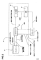
図2を参照すると、コンピュータ支援手術システム(以下、CASシステムという)が50で表され、一般に、センサー装置54に接続されたCASコントローラー52により構成される。かかるセンサー装置54は、本発明の人工股関節置換手術の説明で詳述される、器具56の位置および方向を追跡する。前記コントローラー52は、通常、それにより情報を受け取ったり・送ったりし、かかる情報により人工股関節置換手術中、執刀医が導かれる、ユーザーインターフェースを有するPCユニットである。例えば、モニター、キーボードマウス、および足踏みペダルが、コントローラー52とともに提供可能な、ユーザーコントローラー例である。コントローラー52のデータベースは、データベース58として別個に示されており、通常は、コントローラー52のハードデイスクである。方法100の説明に続いて、好ましいシステム構成についての説明が行われる。
Referring to FIG. 2, a computer-assisted surgical system (hereinafter referred to as a CAS system) is represented by 50, and generally includes a
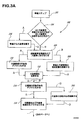
図3を参照すると、本発明に基づく人工股関節置換手術方法の全体が100で示されている。かかる方法100は、単一の方法として示されているが、執刀医には、自身の好みに基づき、以下で説明する様々な選択の余地がある。執刀医の判断に基づき、方法100から複数の方法を派生させることができる。
Referring to FIG. 3, the entire hip replacement surgery method according to the present invention is shown at 100. Although such a
ステップ102において、手術の準備ステップが行われる。すなわち、患者のカルテ情報を作成するため、一般的な患者情報をCASシステム50(図2)に入力することができる。 例えば、名前、誕生日、識別番号、性別等、だけでなく、必要であれば、脚の長さの相違(長い方の脚の識別とともに)等の手術に関するより詳しいデータから構成された、一般的な患者の履歴を入力することができる。例えば、脚の長さの相違は、股関節のX線を用いて測定される。より具体的には、脚の長さの相違は、小転子(lesser trochanters)間の縦の比較から測定される。通常、これらのX線写真は、手術に先立って行われる診断段階中に撮影されるので、これらは、普通、股関節手術に利用可能である。また使用される様々な手術器具の調節も済んでいる。例えば、Jutras等による国際公開番号WO 01/67979 A1により示された調節ベースならびに方法を、調節に用いることもできる。また、ステップ102に含まれる更なる調節ステップにおいて、器具の追跡56とCASコントローラー間の対応を認証することが可能である。
In
一般的な患者情報は、術前に入力可能であることが指摘される。また、一般的な患者情報を入力は、執刀医が関わる必要がないような容易な作業である。しかし、術前の処理を最小化するため、手術の初期段階であって、実際の手術に先立つ短い時間中に、方法100の全てのステップを実施するようにしてもよい。
It is pointed out that general patient information can be entered before surgery. Also, inputting general patient information is an easy task that does not require the surgeon to be involved. However, to minimize pre-operative processing, all steps of the
ステップ102と次の判断104の間に、執刀医が股関節を露出させることにより、手術が開始される。ここでは、コンピュータによる支援は、不要である。
Between
判断104において、執刀医は、骨盤から大腿骨を離す処置(A)、あるいは、大腿骨から大腿骨頭を切除する処置(B)のいずれを行うかの選択を与えられる。以下で説明するように、(A)および(B)のいずれもが、大腿骨および骨盤の両方の基準フレームを取得させるが、(A)と(B)は互いに他を上回る利点がある。参考例として、図3の方法100においては、執刀医の選択に基づき、フローチャートの線が、(A)又は(B)に分けられている。
In
骨盤から大腿骨を離す処置(A)が好ましい場合、臼蓋窩11および大腿骨頭21(図1)の回転の中心は、互いに独立してデジタル化される。(B)において、大腿骨頭21を臼蓋窩11から除去するため、大腿骨20から大腿骨頭21を切除しても、大腿骨頭21は、切断が完了するまで臼蓋窩11から露出せず、これにより、大腿骨20の残りに対する、その回転の中心をデジタル化することができない。したがって、仮定に基づく演算は、回転中心の理論上の計算を可能にする。
When the procedure (A) of separating the femur from the pelvis is preferred, the centers of rotation of the
他方、大腿骨20を離す処置(A)は、ある程度の困難性を示し、大腿骨20が破損(ネック22において)し、靱帯ならびに筋肉に損傷(例えば、過伸展(hyperextension))を与えてしまうというリスクを伴う。処置の安全性から、執刀医によっては(B)の大腿骨頭21の切除の方が好まれる。
On the other hand, the procedure (A) of releasing the
まず処置(A)を詳述し、その次に、処置(B)を説明する。図1(骨パーツの参照のための)および図3を参照すると、(A)の選択に続き、ステップ106において、骨盤10から大腿骨20を離し、臼蓋窩11から大腿骨頭21を除去する。したがって、臼蓋窩11および大腿骨頭21の両方が露出する。
First, the procedure (A) will be described in detail, and then the procedure (B) will be described. Referring to FIGS. 1 (for bone part reference) and FIG. 3, following the selection of (A), in
ステップ108において、追跡基準(器具56に含まれる)が、骨盤10および大腿骨20に固定される。したがって、骨盤10および大腿骨20の両方について、図2のCASシステム50によるそれぞれの追跡基準に応じて、空間における位置と方向を同時に追跡することができる。かかる追跡基準は、手術のコンピュータが支援するステップ中、それぞれの骨に固定されたままである。大腿骨20の除去により、追跡基準が干渉されないことが好ましいが、処理(A)のステップ106の前に、ステップ108を実行してもよいことが指摘される。したがって、CASシステム50は、少なくとも2の追跡基準を同時にリアルタイムで追跡するよう構成される。
In
追跡基準は、骨エレメントのいずれかにマークを施したポイントの形式を採用してもよいことが指摘される。大腿骨20は、ポイントにより完全にマークされている(例えば、物理的あるいは、視覚的なマーカー)が、例えば、骨エレメントにネジ止めされるタイプの追跡基準は、位置と方向が追跡される骨盤10に固定することができる。大腿骨20上のマーク済みポイントを骨盤10上の追跡基準と関連づけるため、骨盤10および大腿骨20が既知かつ再現可能な姿勢である場合には、マーク済みポイントが登録される。その後、手術中の大腿骨20に関する位置ならびに方向の情報を更新するため、既知かつ再現可能な姿勢が再現され、マーク済みポイントが、登録ポインターによってデジタル化される。
It is pointed out that the tracking criteria may adopt the form of points marked on any of the bone elements. While the
また、再現可能な方法で位置させることが可能なポータブル追跡基準を、骨エレメント上に提供することが考えられる。例えば、マーク済みポイントを一つだけ有する代わりに、その上にポータブル追跡基準を位置させるために用いられる3つの非連続なポイントを大腿骨20にマークするようにしてもよい。このようなポータブル追跡基準を用いることにより、3つの非連続なポイントに対しポータブル追跡基準を位置させることによって、大腿骨20に関する位置ならびに方向の情報を得ることができる。ポータブル追跡基準は、骨エレメントにねじ穴を開けることがない点で有益である。
It is also conceivable to provide a portable tracking reference on the bone element that can be located in a reproducible manner. For example, instead of having only one marked point, the
本発明の好ましい実施形態に基づく大腿骨20に固定された追跡基準を用いる方法100を説明する。大腿骨20に固定された追跡基準に代えて、上述の代替方法が使用可能であることも理解される。
A
図1から図3を参照すると、ステップ110において、大腿骨頭21の中心のデジタル化が実行される。例えば、空間で追跡される、自身のチップを有する登録ポインター(器具56から)が、大腿骨頭21の表面上にポインタを登録するために用いられる。したがって、前記チップおよびある表面間の接触ポイントを、追跡基準に応じて登録することができる(ステップ108)。ステップ108において、追跡基準が、大腿骨20および骨盤10に固定されると、大腿骨頭21の表面上のポイントは、大腿骨20の各追跡基準の追跡結果に応じて認識される。CASコントローラー52は、集めたポイントから球形(すなわち、大腿骨頭21)の中心を演算することを可能にするソフトウエアを備えている。また、中心を演算するソフトウエアは、標準および最大偏差(standarad and maximum deviations)を用いて、中心の演算を確認を実行するためにも適用される。例えば、ステップ102におけるパラメーターの設定中の、中心の演算確認に関する排除基準を記録することができる。
With reference to FIGS. 1-3, in
上述のステップ110は、そこから大腿骨の回転中心が演算される、三次元モデルを入手するためには好ましいが、大腿骨の回転中心を得るため他の同様の方法も想定される。例えば、三次元モデルを迅速に作成するため、写真測定スキャンを用いることができ、あるいは、そこから、大腿骨頭の形状を構築することが可能な、術前のコンピュータ断層撮影画像を収集することもできる。 Step 110 described above is preferred for obtaining a three-dimensional model from which the rotational center of the femur is calculated, but other similar methods are envisioned for obtaining the rotational center of the femur. For example, photometric scans can be used to quickly create 3D models, or pre-operative computed tomography images can be collected from which femoral head shapes can be constructed. it can.
この情報が、大腿骨インプラントの選択段階において執刀医を導くことが可能であるため、球形(すなわち、大腿骨頭21)の直径を表示することができる。CASコントローラー52上の表示を修正するため、大腿骨の回転中心および大腿骨頭21の直径を用いることが可能である。CASコントローラー52のデイスプレイユニット上にCT画像を表示させることができるが、前記方法100は、CT画像を用いないことが好ましい。したがって、骨盤10および大腿骨20の全体の視覚画像は、一般的な参照のために表示可能であるが、これらの画像は、処置(A)における大腿骨20に関するステップ110において演算され、骨盤10に関するステップ114において演算される、回転中心および直径に応じて測定される。
Since this information can guide the surgeon in the selection phase of the femoral implant, the diameter of the sphere (ie, the femoral head 21) can be displayed. In order to correct the display on the
ステップ112において、処置(A)で識別された大腿骨頭21の中心を追跡基準(ステップ108)に応じて用いることにより、大腿骨頭21の切除が実行される。
In
図1から図3を参照すると、ステップ114においては、臼蓋窩11の表面上の基準点をとるとともに、臼蓋窩の回転の中心を見つけるため、ステップ110で述べたCASコントローラー52の中心演算ソフトウエアを用いることにより、寛骨臼(acetabular)の回転中心のデジタル化が行われる。したがって、臼蓋窩の回転の中心は、骨盤10上の追跡基準に応じて認識される。処置(A)において、寛骨臼(acetabular)の回転中心のデジタル化(ステップ114)は、大腿骨頭21の回転中心のデジタル化(ステップ110)とは独立して行われることに注意すべきである。
Referring to FIGS. 1 to 3, in
ステップ116は、臼蓋窩および大腿骨座標系(femoral coordinare system)、すなわち、基準の臼蓋窩および大腿骨フレームをデジタル化したものから構成される。 Step 116 is comprised of a digitized acetabular and femoral coordinate system, ie, a reference acetabular and femoral frame.
臼蓋窩座標系(acetabular coordinate system)は、登録ポインタを用いてデジタル化される。本発明の好ましい実施形態において、臼蓋窩座標系を作り出すため、骨盤10上の3つのポイントが取られる。図1を参照すると、手術側の腸骨稜(iliac crest)12上に1つのポイント、逆側面の腸骨稜13上に1つのポイント、ならびに、骨盤10の2の一般節(public tubercles)14のいずれかの上に1つのポイントがある。おおまかに位置あわせを行うため、腸骨稜12、13の最外部の前方のポイントにおいては、腸骨稜12、13上にデジタル化されたポイントが取られる。その上では軟組織が比較的薄いので、腸骨稜12、13上にデジタル化されたポイントは、骨盤を覆う軟組織上で直接取られることが好ましい。一般節14上のポイントにより、第一面である前額面が完成する。第二面である側面は、前額面に対して垂直であり、腸骨稜上のポイントを含んでいる。第二面である矢状面は、前額面および側面に対して垂直である。
The acetabular coordinate system is digitized using a registration pointer. In the preferred embodiment of the present invention, three points on the
前額面に関する補足情報は、患者の様々な姿勢について入手することができる。例えば、座る、立つ、および歩く、姿勢に関する情報を収集するため、追跡可能基準を用いることができる。これらの姿勢が、手術中に患者がその姿勢にある通常の寝ている姿勢からは得られない情報を提供することができるので、この情報は、前額面の方向を調節するために用いることができる。また、この情報は、インプラントの前傾位置決め(anteversion positoning)に影響を及ぼすことができる。 Supplemental information regarding the front face value is available for various patient postures. For example, trackable criteria can be used to gather information about sitting, standing, and walking, posture. Since these postures can provide information that cannot be obtained from a normal sleeping posture in which the patient is in that posture during surgery, this information can be used to adjust the orientation of the frontal face. it can. This information can also affect the anteversion positoning of the implant.
後に、手術において、基準(例えば、比較ベース)として用いられる、患者の臼蓋窩の前傾および/又は傾斜値を入手することができる。これを行うため、ポイントは、臼蓋窩11のほぼ円形の端部上でデジタル化され(器具56から登録ポインターを用いて)、これらのポイントから、ある平面が定義される。この平面に対する法線は、寛骨臼の前額面と側面との交角を有する前傾角度を与えるため寛骨臼側面(ステップ116において定義された)上に突出している。この平明面に対する法線は、寛骨臼の矢状面上に頭方−尾方軸(cranial-caudal)(y)を有する傾斜角度を与えるため、寛骨臼の矢状面(ステップ116において定義された)上に突出している。 Later, the patient's acetabular anteversion and / or inclination values can be obtained that are used as a reference (eg, a comparison base) in surgery. To do this, the points are digitized on the generally circular end of the acetabulum 11 (using a registration pointer from the instrument 56), from which a plane is defined. The normal to this plane protrudes on the acetabular lateral surface (defined in step 116) to provide an anteversion angle having the angle of intersection of the acetabular frontal plane and side. The normal to this plain surface gives an angle of inclination with a cranial-caudal axis (y) on the sagittal plane of the acetabulum (defined in step 116). Protruding).
本発明の好ましい実施形態においては、脚上の5つの基準ポイントを、大腿骨座標系を作成するソフトウエアを備える、CASコントローラー52に提供することにより、ステップ116において大腿骨座標系 がデジタル化される。図1を参照すると、最初のポイントは、大腿骨20の大きい方の転節(greater trochanter)23のチップ上で取られ、大腿骨20の軸の構造上の始点として定義される。次に、大腿骨20の大腿骨内側および外側上顆24、25上で、それぞれポイントが取られる。それとの取り付けにおける内側上顆と外側上顆間の中間点が、大腿骨の構造上の終点として定義される。膝で脚が曲げられた状態において、四番目および五番目のポイントが、脛骨30のくるぶし(malleolus)31および腓骨40の脛骨果41上で取られる。脚を膝で曲げることにより、脛骨30は、大腿骨20の後顆(posterior condyles)26上に立つことになる。したがって、外果窩ポイント(malleoli points)の内側および外側の配列された中間点が、構造上の軸を有する平面(すなわち、矢状面)を定義し、当該矢状面に対する膝の軸が法線となるものと推測される。前額面は、その中に伸びる構造上の軸を有する、前記矢状面に対して垂直である。側面は、矢状面および前額面に対して垂直であり、どのような高さに位置することが可能である。構造上の軸およびデジタル化された外果窩領域の中間点を用いることにより、大腿骨座標系、すなわち、基準大腿骨フレーム、が完成する。外果窩領域の中間点を得るため、二つのポイントを測定する必要がないことに注意すべきである。前記矢状面に、この後者のポイントが存在するので、外果窩領域の中間点でポイントを取ることのみが要求され、オペレーターによって、おおよその位置に置くようにしてもよい。
In a preferred embodiment of the invention, the femoral coordinate system is digitized at
ここで説明された突出値(例えば、傾斜、前傾等)は、臼蓋窩および大腿骨座標系に基づくことが指摘される。ステップ116の好ましい方法に加え、寛骨臼および大腿骨座標系をデジタル化する別の方法を用いることが予想されるので、前記突出値は、他の臼蓋窩および大腿骨座標系と関連する。
It is pointed out that the protrusion values described here (eg tilt, anteversion etc.) are based on the acetabular and femoral coordinate systems. In addition to the preferred method of
ここでは、処置(A)が説明されたので、移動なしで大腿骨20の切除を伴う処理(B)について説明する。図3を見るとすぐに判るように、処理(A)において説明されたいくつかのステップは、処置(B)においても実行されることが理解される。したがって、特に述べない限り、対応するステップは、同じ特徴を有しており、ステップ(B)においてその詳細を説明することはない。図1および図3に示すように、切除(B)を続行する判断に続く手術の最初のステップは、追跡基準が骨盤10および大腿骨20に固定される、ステップ108である。
Here, since the treatment (A) has been described, the processing (B) involving excision of the
図1および図3を参照すると、ステップ200は、それぞれの追跡基準に応じて追跡骨盤10と大腿骨20間の相対位置の登録を構成する。脚は、単にまっすぐな部分として残され、それぞれ対応する骨に固定された追跡基準間の相対位置が取り込まれる。
Referring to FIGS. 1 and 3,
処理(B)において、大腿骨から大腿骨頭21を切除するステップ112は、ステップ200に続いて行われる。したがって、骨盤10の臼蓋窩11が露出し、寛骨臼の回転中心のデジタル化が行われるステップ114が、それに続く。前述のように、寛骨臼の回転中心のデジタル化は、骨盤10に固定された追跡基準に応じて行われる。
In the process (B), the
ステップ202は、大腿骨の回転中心の演算を含んでいる。この演算において、処理(B)の前のステップ114において演算された寛骨臼の回転中心は、大腿骨の回転中心と一致するという仮定がなされる。しかし、骨盤10および大腿骨20は、ステップ112の大腿骨頭21の切除のために分離されているので、大腿骨の回転中心の位置は、ステップ200において得られる骨盤10および大腿骨20間の相対位置に応じて演算される。
Step 202 includes computing the center of rotation of the femur. In this calculation, it is assumed that the rotation center of the acetabulum calculated in
ステップ116は、臼蓋窩および大腿骨座標系、すなわち、基準の臼蓋窩および大腿骨フレーム、のデジタル化から構成される。 Step 116 consists of digitizing the acetabular and femoral coordinate system, ie, the reference acetabular and femoral frame.
したがって、ここで、処置(A)および(B)は、同じデータを収集している。この時点で、まず骨盤へインプラントを挿入する(C)か、あるいは、大腿骨インプラントを挿入するため大腿骨の準備をする(D)か、について執刀医に選択肢を与える判断150に続く。
Thus, here, treatments (A) and (B) are collecting the same data. At this point, the
再度述べるが、処置(C)および(D)は、それぞれの利点を有する。処置(C)は、好ましい実施形態であり、ステップ数が少なくとも一つ少ない可能性が高い。自身の大腿骨頭21を除去するために切除されたばかりの大腿骨への作業を伴うので、一部の執刀医は、処置(D)を好むであろう。 Again, treatments (C) and (D) have their advantages. Treatment (C) is a preferred embodiment and is likely to have at least one fewer steps. Some surgeons will prefer procedure (D) because it involves working on a femur that has just been resected to remove its own femoral head 21.
まず処置(C)について説明し、続いて処置(D)につい手説明を行う。 First, the procedure (C) will be described, and then the procedure (D) will be described.
ステップ152は、処置(C)の最初のステップであり、骨盤へインプラントを挿入するための臼蓋窩の準備を構成する。通常、臼蓋窩の準備は、(CASシステム50の器具56中の)リーマー(reamer)により実行される。前の臼蓋窩の回転中心は、それが前のステップ114において入手されていたので、骨盤10に固定された追跡基準に応じて認識されている。前記リーマーは、リーマーの上のカップ器具の作動軸がCASコントローラー52上に表示されるよう、その位置ならびに方向について追跡することが好ましい。
Step 152 is the first step in procedure (C) and constitutes preparation of the acetabulum for insertion of the implant into the pelvis. Typically, acetabular preparation is performed by a reamer (in
ステップ152において、デジタル化された寛骨臼の回転中心と比較した新たな寛骨臼の回転中心の位置を表示するため、執刀医により選ばれた骨盤用インプラントの直径が用いられる(ステップ114)。例えば、回転中心間の距離は、前のステップ116においてデジタル化された臼蓋窩座標系に応じて、数字で表示させる(例えば、mmで)ことも可能である。また、リーミングにおいて執刀医を導くため、リーマーの作動軸の前傾および勾配を、臼蓋窩座標系に応じて数字で示すことができる。より正確には、前記の前傾は、寛骨臼の前額面および側面と寛骨臼の側面上のリーマーの突起の軸との間の角度として演算され、前記傾斜は、リーマー軸と、臼蓋窩座標系の矢状面上の頭方−尾方軸(y)の角度である(ステップ116)。
In
ステップ154は、骨盤インプラントの臼蓋窩11への挿入から構成される。(器具56中の)追跡された衝撃部材(tracked impactor)を用いることが好ましい。骨盤インプラントのサイズが選択されると、当該骨盤インプラントの前傾ならびに傾斜を求めるため、衝撃部材を追跡するためにその直径および衝撃部材と骨盤インプラント間の既知の関係が用いられる。また、現在およびデジタル化された回転中心間の距離を表示することも可能である。したがって、執刀医は、衝撃部材の使用中、骨盤インプラントが、その回転中心の一定箇所であって、[前傾および傾斜に対する(ステップ152)]脚の動きならびに安定性が最大になるような方向に位置するよう導かれる。
Step 154 consists of inserting a pelvic implant into the
骨盤インプラントは、このような点において骨盤に固定されるが、骨盤インプラントの位置および方向を調節することも可能である。まず、追跡された衝撃部材を有する骨盤インプラントを操作するためのレバーとして機能させるため追跡された衝撃部材を、骨盤インプラントに再接続するようにしてもよく、衝撃部材を追跡することにより、位置および方向情報(例えば、前傾および傾斜)を演算することが可能になる。これに代え、骨盤インプラントの円形端部上のポイントは、ある平面を定義するためデジタル化してもよく、前に示唆したように、寛骨臼についての情報を得るため、この面に対する法線が、前傾および傾斜を演算するために用いられる。この代替アプローチは、更なる固定ためのねじ穴であって、それを通じて、インプラントが位置及び方向を変更可能なものを有する骨盤インプラントに非常に適している。 The pelvic implant is fixed to the pelvis in this respect, but the position and orientation of the pelvic implant can be adjusted. First, the tracked impact member may be reconnected to the pelvic implant to function as a lever for manipulating the pelvic implant having the tracked impact member, and by tracking the impact member, the position and Direction information (eg, forward tilt and tilt) can be calculated. Alternatively, the points on the circular end of the pelvic implant may be digitized to define a plane and, as suggested earlier, the normal to this plane is used to obtain information about the acetabulum. Used to calculate forward tilt and tilt. This alternative approach is very suitable for pelvic implants with screw holes for further fixation through which the implant can change position and orientation.
ステップ156は、大腿骨ターゲットの高さを作り出すステップから構成される。かかるターゲット高さは、大腿骨の回転中心に関する所望の位置であり、以下のようにして演算される:
(target height)=(ΔPELVIC COR)- (initial ΔLL)
ここで、(ΔPELVIC COR)は、頭方−尾方(y)方向(正の値を有する頭方の変位)における、デジタル化された寛骨臼の回転中心(すなわち、ステップ114)に対する、インプラントの回転中心の変位(すなわち、ステップ154)であり、(initial ΔLL)は、当初取得された脚の長さ(initially acquired limb length)の相違(ステップ102)である。
Step 156 consists of creating a femoral target height. Such a target height is a desired position with respect to the rotational center of the femur and is calculated as follows:
(target height) = (Δ PELVIC COR )-(initial Δ LL )
Where (Δ PELVIC COR ) is the implant for the digitized center of rotation of the acetabulum (ie, step 114) in the cranial-caudal (y) direction (cranial displacement with a positive value). (Initial Δ LL ) is the difference in the initially acquired limb length (step 102).
図1および図3を参照すると、ステップ158は、大腿骨インプラントを挿入するための大腿骨20の準備から構成される。より正確には、髄内管(intramedullary canal)27の軸が、前記管における関連するポイントにより、大腿骨20に固定された追跡基準に応じてデジタル化される。前記髄内管27は、ステップ112において実行された大腿骨頭21の切除により露出する。本発明のある実施形態において、管27の複数のポイントは、(器具56中の)ポインターを様々な深さに挿入し、追跡することによりデジタル化される。空間において位置と方向を追跡可能であり、かかる追跡に関する軸が既知となる、千枚通し(awl)のような器具を用いることも想定できる。髄内管の内径が、千枚通しとほぼ等しい深さで、髄内管内に前記千枚通しを挿入することができる。かかる深さにおいて、千枚通しは、髄内管のほぼ中心に位置するので、千枚通しの仮想軸を、髄内管の仮想軸として登録することができる。
Referring to FIGS. 1 and 3,
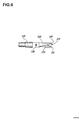
図4を参照すると、本発明の好ましい実施形態に基づく管デジタイザー(canal digitizer)が、300で示される。かかる管デジタイザー300は、そのチップを、髄内管27の中心に正確に位置させるため用いることができ、これにより、管27の中央に位置する仮想軸をデジタル化することが可能となる。管デジタイザー300の詳細については、以下で説明する。
Referring to FIG. 4, a tube digitizer according to a preferred embodiment of the present invention is shown at 300. Such a
また、ステップ158は、その中に大腿骨インプラントを挿入することを考慮した上で、髄内管27に石目やすりをかけること(rasping)を含んでいる。石目やすり(rasp)は、CASシステム50器具56の一部であるので、その位置ならびに方向が追跡される。髄内管27に変更を加える前記石目やすりの器具部分および大腿骨インプラントの両方は、所定形状を有している。石目やすりは、それぞれが、大腿骨インプラントの骨係合部分とほぼ同じ形状の工具端を有することが好ましい。また、前記やすりは、当該やすりの各サイズごとに同様の大腿骨インプラントを有した、異なるサイズに設けてもよい。したがって、管の変更中の、大腿骨座標系に対する前記やすりの位置および方向の追跡結果が、大腿骨インプラントの現在の位置および方向の演算に用いられる。大腿骨インプラントの現在の位置および方向を数字で表すため、複数のガイドパラメーターが、執刀医に表示され、その下に記載される。
Step 158 also includes rasping the
追跡されたやすりから演算された大腿骨インプラントの前傾は、ステップ116で演算された大腿骨座標系に基づいて、数値的に(例えば、角度で)表示される。かかる前傾は、前額面および側面の交点と、前記側面上(ステップ116)にある首の仮想軸の突起(大腿骨インプラントに関して予想されたもの)との間の角度によって表される。
The anteversion of the femoral implant calculated from the tracked file is displayed numerically (eg, in an angle) based on the femoral coordinate system calculated in
執刀医に提供される他のガイドパラメーターは、追跡されたやすりの内反/外反角度と等しい、大腿骨インプラントの内反/外反角度である。かかる角度は、髄内管の仮想軸の突起と、前記側面上(ステップ116)にあるヤスリの長手方向の仮想軸の突起との間で測定され、執刀医に対し、角度で表示される。 Another guide parameter provided to the surgeon is the varus / valgus angle of the femoral implant, which is equal to the varus / valgus angle of the tracked file. Such an angle is measured between the virtual axis projection of the intramedullary canal and the file's longitudinal virtual axis projection on the side (step 116) and displayed to the surgeon in angle.
また、執刀医に提供される他のガイドパラメーターは、大腿骨の回転中心[すなわち、ステップ106において、分離処置(A)のためにデジタル化され、あるいは、ステップ202において、切除処置(B)のために演算された]と、大腿骨の現在の回転中心との間の距離である。大腿骨の現在の回転中心は、大腿骨インプラントの形状(たとえば、球頭のサイズ)およびヤスリの追跡結果に応じて演算される。かかる距離は、大腿骨座標系(ステップ116)に基づいてX、Y、およびZ値で(例えば、mm)で表すことが可能である。
Also, other guide parameters provided to the surgeon may be digitized for the separation center (ie, at
さらに、執刀医に提供される他のガイドパラメーターは、現在の脚の長さの相違である。現在の脚の長さの相違(current ΔLL)は、以下のように演算される:(current ΔLL)=(initialΔ LL)−(ΔPELVIC COR)+(ΔFEMUR COR)
ここで、(ΔFEMUR COR)は、上記ステップ158で演算されたYの値であり、(ΔPELVIC COR)および(initialΔ LL)は、ステップ156で演算されている。現在の脚の長さの相違は、脚全体の長さ、あるいは、値が0の場合に脚の長さが等しいことを表すよう脚の長さの相対値としてCASシステム50により表示可能である。
In addition, another guide parameter provided to the surgeon is the difference in current leg length. The difference in current leg length (current Δ LL ) is calculated as follows: (current Δ LL ) = (initial Δ LL ) − (Δ PELVIC COR ) + (Δ FEMUR COR )
Here, (Δ FEMUR COR ) is the value of Y calculated in
執刀医に提供される他のガイドパラメーターは、大腿骨インプラントのオフセットである。かかるオフセットは、寛骨臼の回転中心と、側面上のインプラントの仮想軸(すなわち、以前定義した大腿骨の構造的な仮想軸)間の距離である。上述の方法100に用いられることが想定される大腿骨インプラントのタイプは、様々なサイズで提供されても良く、大腿骨インプラントのサイズは、インプラントのネックに沿って回転する、様々な大腿骨の回転中心を有しても良いことが指摘される。ただし、オフセットおよび脚の長さ(limb length)の両方に影響を及ぼすので、大腿骨インプラントのサイズについて正しい識別番号が与えられなくてはならない。
Another guide parameter provided to the surgeon is the femoral implant offset. Such an offset is the distance between the center of rotation of the acetabulum and the virtual axis of the implant on the side (ie, the previously defined structural virtual axis of the femur). The types of femoral implants envisioned for use in the
また、測定された大腿骨と寛骨臼の距離の合計がX軸に表示されることも望ましい。 It is also desirable that the total distance between the measured femur and acetabulum is displayed on the X axis.
処置(C)において、執刀医が、やすりがけされた髄内管27に満足すると、大腿骨インプラントが挿入される。ステップ160は、髄内管27に大腿骨インプラントを挿入するステップから構成される。大腿骨インプラントは、髄内管を変更した器具56の追跡結果から演算された位置および方向に存在することが予想される。しかし、位置および方向を求めるため、大腿骨インプラントの追跡結果に応じ、CASコントローラー52により演算されたインプラントの回転中心を用いて大腿骨インプラントを追跡することも推測される。かかるステップは、インプラントが正確な位置に存することを促進する。CASコントローラー52は、大腿骨インプラントが挿入されると大腿骨20について、あるいは、骨盤インプラントが挿入されると骨盤10について、自身の表示を変更することが可能である(ステップ154)。
In procedure (C), when the surgeon is satisfied with the filed
ステップ162は、股関節の動作範囲を分析するステップから構成される。かかる動作範囲は、以下のパラメーターにより算定することができる:内転(aduction)/外転(abduction)の屈曲/伸長、および、脚の内部回転/外部回転の角度。これらの角度は、ステップ116においてデジタル化された両方の座標系に基づいて測定され、最小および最大角度の値を、患者の履歴とともに記録することができる。
Step 162 comprises the step of analyzing the motion range of the hip joint. Such range of motion can be calculated by the following parameters: flexion / extension of aduction / abduction, and angle of internal / external rotation of the leg. These angles are measured based on both digitized coordinate systems in
ステップ164は、人工股関節置換手術について、コンピュータの支援が終了することを合図する。 Step 164 signals the end of computer support for the hip replacement surgery.
このようにして、処置(C)の詳細を説明したが、ここでは、骨盤インプラントを挿入する前に、大腿骨の準備を行う処置(D)を説明する。処置(D)において、ステップ250は、判断150に続き、ステップ158と同じ動作によって構成される。すなわち、骨盤インプラントを挿入するため、大腿骨の準備が行われる。しかし、実際の骨盤インプラントの回転中心は、デジタル化された臼蓋窩の回転中心(ステップ114)と同じであると仮定される。したがって、かかるデジタル化された臼蓋窩の回転中心は、執刀医に対し、様々なガイドパラメーターを提供するのに用いられる。
Thus, the details of the treatment (C) have been described. Here, the treatment (D) for preparing the femur before inserting the pelvic implant will be described. In the procedure (D),
ステップ250に続き、処置(D)は、処置(C)において実行されるステップ152、154ならびに156を備えている。ステップ154においては、実際の骨盤インプラントの回転中心が得られることが指摘される。
Following
252の判断においては、実際の骨盤インプラントの回転中心と、ステップ250において大腿骨の準備に用いられたデジタル化された臼蓋窩の回転中心との間で比較がなされる。これらの値の間に相違がある場合、ステップ158で示すように、大腿骨の補正が必要となる。相違がない場合、骨盤インプラントを骨盤に挿入することができる。
In the determination at 252, a comparison is made between the actual center of rotation of the pelvic implant and the digitized acetabular center of rotation used to prepare the femur in
その後、ステップ162および164が続き、処置(D)が終了する。 Thereafter, steps 162 and 164 continue, and the procedure (D) is completed.
方法100の詳細が説明されたが、ここでは、本発明の好ましい実施形態に基づくCASシステム50を説明する。
Having described the details of the
図2を参照すると、オペレーター(例えば、執刀医)は、Sで示され、CASシステム50により手術を行うよう導かれる。より具体的には、オペレーターSは、コントローラー52のインターフェース(例えば、マウス、デイスプレイユニット、キーボード、音声発生装置)を用いてCASシステム50のコントローラー52と通信する。図2に示すように、コントローラー52は、方法100において、オペレーターSに対してCASを介してガイド情報を提供する。ガイド情報は、例えば、データベース58からコントローラー52により取り込まれ、オペレーターSが器具56を操作するよう導く。
Referring to FIG. 2, an operator (eg, a surgeon) is indicated by S and is guided by the
各器具56は、与えられたそのコンポーネントの位置および/又は方向を演算するよう、センサ装置54により、空間において位置および方向を追跡可能である。骨の基準となるフレームを生成するため、器具56は、骨に固定可能で追跡可能な器具等の基準器具を含むことが、一般的で基本的な条件である。必要とされる他の器具56の一つに、骨についての表面情報(ステップ110、114、116等)を収集することを可能にする登録器具がある。前述のように、かかる登録器具は、登録ポインター、追跡された写真測定センサー等であってもよい。最後に、必要な器具56には、ステップ152および158で、その使用についてそれぞれ説明がなされた、リーマーおよびやすり等の骨変更器具が含まれる。また、器具56は、挿入中に、オペレーターを導くため、位置および方向を追跡可能な骨盤(衝撃部材)および大腿骨インプラントを含んでいる。器具に関する情報(例えば、形状、チップの位置)は、コントローラー52によって知られ(又は、データベース58から取り込み可能であり)、あるいは、様々な校正を用いて決定可能であることが指摘される。
Each
センサ装置54は、コントローラー52に接続され、位置および方向の追跡結果をコントローラー52に転送する。かかる位置および方向の追跡結果は、CASに関するパラメーターを演算するためコントローラー52によって用いられる。より正確には、基準器具および登録器具の位置および方向の追跡結果は、ステップ110、114ならびに116で説明したように、骨盤および大腿骨の基準フレームを作り出すために用いられる。図2に示すように、基準情報のフレームは、例えば、コントローラー52のデイスプレイユニットを用いてオペレーターSに提供される。
The
骨盤インプラントについては、ステップ114で説明したように、基準フレームに基づいて最初の回転中心が演算される。寛骨臼の回転中心は、その中へ骨盤インプラントを挿入することを考慮して、臼蓋窩を変更することの基準としての基準骨盤フレームと共に用いられる。骨盤インプラントが所望される位置は、ステップ156に基づいてコントローラー52によって演算され、その中へ大腿骨インプラントを挿入することを考慮して、髄内管を変更する基準として用いられる。データベース58は、演算を行うため、コントローラー52により取り込まれた情報を記憶する。
For the pelvic implant, the first center of rotation is calculated based on the reference frame, as described in
現在の骨盤および大腿骨インプラントの位置ならびに方向は、骨変更器具の位置および方向の追跡結果、ならびに、各インプラントの位置及び方向の追跡結果に応じて演算される。これは、方法100のステップ154および158/252に基づいて実行される。コントローラー252は、オペレーターSを導くために表示される演算を行うため、センサー装置54の出力およびデータベース58に記憶された情報を再び用いる。
The current position and orientation of the pelvic and femoral implants are calculated according to the results of tracking the position and orientation of the bone change instrument and the results of tracking the position and orientation of each implant. This is performed based on
CASシステム50は、動的あるいは静的な追跡のいずれによっても動作可能である。本発明の好ましい実施形態において、センサー装置54は、コントローラー52内に適切なソフトウエアを有する、NDI社のポラリス(商標)光学追跡装置である。ポラリス(商標)光学追跡装置を用いることにより、従来の反射式球体等の静的な検出装置が、位置及び方向を求めるために空間で追跡されるパターンにおいて用いられる。追跡されることが要求される各器具56が、固有の検出パターンを有する。
The
CASシステム50は、方法100を通じて執刀医を導かなければならず、執刀医が正しいステップに従って処置を行う事を促進するため、関連情報が表示される。例えば、脚の長さの相違値が与えられた場合、入手した測定値(the reading obtained)を説明するために、頭方−尾方の約束事(crania-caudal convention)を表示することができる。執刀医を導くため、例えば、様々な骨の上で、与えられた順序、あるいは、正しい位置において基準点を取る等のアニメーションを自動的に開始するようにしてもよい。
The
図4、図5Aおよび5Bを参照すると、伸長シャフト302、ハンドル部304、ピストン306、検出装置ベース308、ならびに、センタリング機構309、を有する管デジタイザー300が示されている。
Referring to FIGS. 4, 5A and 5B, a
前記シャフト302は、中空であり、外表面310および自由解放端312を有している。前記シャフト302は、デジタイザー300が管内に挿入される際、器具ハンドラーがデジタイザー300の挿入深さの表示を有するよう、目盛りが付けられている。図5Aに示すように、自由解放端312にスプリッター314が設けられ、一対の拡張部の間に保持されている。
The
ハンドル部304は、一対のラジアルフランジ320を有している。検出装置ベース308は、ラジアルフランジ320の一の端部から外側に突出している。かかる隣接フランジ320は、ピストン306に近接し、ピストン306を内側に押すため、器具ハンドラーによってレバレッジとして用いられる。裾広がりのチップ322がフランジ320に隣接し、伸長シャフト302が管内に完全に挿入された場合に、管の壁に対して接すると、デジタイザー300が中心に位置することを可能とする。また、以下で説明する目的のため、ハンドル部304は、隣接フランジ320に近接するガイドチャネル325を有する、内部孔324を定義する。
The
図4に示すよう、裾広がりのアダプター323は、選択的に、シャフト302上にスライド係合するよう設けることが可能である。かかる裾広がりのアダプター323は、ハンドル部304の裾広がりのチップ322と同じ役割を果たすが、シャフト302を、様々な深さで管内に挿入できるよう、シャフト302から取り除くことが可能である。
As shown in FIG. 4, a flared
センタリング機構309は、シャフト302内に同心的に配置された細いロッド326を有している。かかるロッド326は、その端部においてピストン306に接続され、図6において最もよく示されているように、その端部においてそれに対して旋回可能に設けられた一対のフィンガー328および330を有している。 図5Aおよび5Bに戻って、バネ332は、ロッド326の近接部分を取り囲み、ロッド326が近接する方向に付勢される、すなわち、ピストン306が、ハンドル部304から離れて保持されるよう、ハンドル部304の内部孔324の表面と接触する。したがって、器具を操作するものによってピストン304が押されると、ロッド326は、端の方向へ移動するが、ピストン306を離すと端部に復帰する。バネ332は、その近接端部において、例えば、その間に溶接することによりピストン306に固定される。
The centering
ピストン306は、その近接端部においてピン327を有する。かかるピン327は、ハンドル部304の孔324のガイドチャネル325と協力して係合する。したがって、ピン327がガイドチャネル325から外れるまで、後者を前者へとガイドすることにより、ピストン306/センタリング機構309のアセンブリを、シャフト302/ハンドル部304のアセンブリから迅速に取り外すことができる。かかるガイドチャネル325は、ピン327が孔324内の肘部325’を通り過ぎると、ピストン306/センタリング機構309のアセンブリが捕らえられ、直線部分325’’における移動は自由となるような、ハンドル部304に対して固定された肘部325’(図5B)および直線部325’’を有している。このアセンブリは、内部キャビテイー324およびシャフト302内部の殺菌を促進することが好ましい。
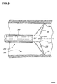
図6から図8を参照すると、ロッド326の端部におけるフィンガー328および330は、フィンガーから突出するストッパー334により互いに分離された、それぞれのチップ329および331を保持する。これにより、フィンガー328および330は、スロット336を定義する。かかるフィンガー328および330は、ピボット338により保持される。前記チップ329および331の双方は、旋回ポイント338から同じ距離にある。
Referring to FIGS. 6-8,
ピストン306が内側に押されると、ロッド326は、スプリッター314がスロット336に係合するよう、シャフト302の自由解放端312に向かって移動する。図8で最もよく表されているように、その際、フィンガー328および330は、互いに離れるよう導かれる。デジタイザー300が、図8で340として示された管内に存在する場合、フィンガー328および330が、デジタイザー300を管内の中央に位置させる。また、他の構成を採ることも可能である。例えば、フィンガー328および330が、固く屈曲する共通の素材から突出する2のブレードであって、スプリッター314と係合すると、ブレードが離れるよな構成の場合、旋回ポインを設けない解決策も考えられる。髄内管中で膨張することにより、自らセンタリングを行う膨張可能な端部を有する伸長シャフト302を備えることも考えられる。
When the
ロッド326は、ピストン306/センタリング機構309(ロッド326を含む)のアセンブリが、シャフト302/ハンドル部304にねじ込み挿入された場合に、その端において、フィンガー328および330がスプリッターの邪魔をしないよう、一定の長さに設けられている。かかる妨害は、ピン327が、内部孔324において、ガイドチャネル325の肘部325’を通り過ぎることを阻止する。他の可能な構成としては、ピストン306とロッド326との間に軸の回転自由度(axial rotational degree of freedom)を設けることである。したがって、フィンガー328および330と、スプリッター314の係合が、内部孔324のガイドチャネル325におけるピストン306のピン327の係合を邪魔することがない。これは、ロッド326の端部に環状の溝を設け、溝339とピストン306間に対応する係合ピン341を設けることにより達成される。
The
デジタイザー300は、CASシステム50(図2)等の追跡システムと共に用いられる。CASシステム50が、光学追跡システムを備えているのが好ましいので、デジタイザー50は、検出装置の支柱から構成される検出装置ベース308を有するよう表されている。より正確には、前記検出装置ベース308は、その自由端において、支持プレート344を伴うアーム342を有している。スナップ式フィンガー(snap-fit fingers)346は、自身とのスナップ止め係合を行う検出装置を受けるために設けられる。例えば、前記検出装置は、その一つが、図4において、フィンガー346の1つにスナップ止めされる、ふちの上に348として示されている、従来の反射式球体であってもよい。追跡装置が、そのために構成されている場合、デジタイザー300が、動的な検出装置を備えるようにしてもよいことは明らかである。
The
デジタイザー300とともに用いられる追跡システムは、ベース308上の検出装置とシャフト302のチップ間の関係を認識していなければならない。かかる関係は、校正ベース(図2の器具56に関して前に説明したように)を用いて、校正段階において決定することができる。したがって、管内でデジタイザー300が安定すると、検出装置の位置および方向を登録することができ、その後、シャフト302のチップが位置する、管の中心点を演算することが可能となる。
The tracking system used with the
Claims (20)
空間で位置及び方向を追跡可能な、大腿骨の基準フレームを取得するステップ、
大腿骨インプラントのデジタルモデルを提供するステップ、
前記脚の長さに応じて、前記大腿骨の基準フレームに対する前記大腿骨インプラントの所望のインプラント位置を演算するステップ、および
前記所望のインプラント位置に対する現在のインプラントの位置および方向に関する情報を提供することにより、前記大腿骨インプラントの大腿骨への次回の挿入のため、前記大腿骨を変更することについてオペレーターを導くステップであって、前記現在のインプラントの位置および方向は、前記大腿骨インプラントのデジタルモデル、および、前記大腿骨インプラントを受け入れるために前記大腿骨を変更させる少なくとも一の手術器具の位置及び方向に関するリアルタイムの追跡結果、に応じて演算されるもの、を備えたこと、
を特徴とするもの。 Surgical treatment using a position tracking system in computer assisted surgery to guide the operator about inserting the femoral implant into the femur, depending on the limb length and orientation of the femoral implant Is a method of performing
Obtaining a femoral reference frame capable of tracking position and orientation in space;
Providing a digital model of the femoral implant;
Calculating a desired implant position of the femoral implant relative to a reference frame of the femur as a function of the length of the leg, and providing information regarding the current implant position and orientation relative to the desired implant position Guiding the operator about changing the femur for the next insertion of the femoral implant into the femur, wherein the position and orientation of the current implant is a digital model of the femoral implant And a real-time tracking result regarding the position and orientation of at least one surgical instrument that changes the femur to receive the femoral implant.
It is characterized by.
を特徴とするもの。 The method according to claim 1, wherein the information regarding the current implant position and orientation includes: varus / valgus angle of the femoral implant, anteversion of the femoral implant, and Including at least one of the femoral implant offsets;
It is characterized by.
を特徴とするもの。 The method according to claim 1, wherein the step of guiding the operator about changing the femur is repeated following the change in the desired implant position caused by a change in the center of rotation of the acetabular.
It is characterized by.
を特徴とするもの。 The method according to claim 1, further comprising guiding the operator to insert the femoral implant into an intramedullary canal by tracking the position and orientation of the femoral implant during the insertion. Having,
It is characterized by.
を特徴とするもの。 The method according to claim 1, wherein the reference frame of the femur is obtained during surgery.
It is characterized by.
空間において位置および方向を追跡可能な基準システムを、前記大腿骨上に位置させるステップ、
前記骨盤から前記大腿骨の位置をずらすステップ、
前記基準システムに応じて、前記大腿骨頭の表面のデジタルモデルを作り出すステップ、および
前記大腿骨頭の表面の前記デジタルモデルに応じて前記大腿骨頭の中心を演算するステップ、を実行することにより行われること、
を特徴とするもの。 6. The method according to claim 5, wherein the reference frame of the femur includes a femoral head center, and obtaining the femoral head center comprises:
Positioning a reference system on the femur that can track position and orientation in space;
Shifting the position of the femur from the pelvis,
Generating a digital model of the surface of the femoral head according to the reference system and calculating a center of the femoral head according to the digital model of the surface of the femoral head. ,
It is characterized by.
前記大腿骨の解剖学上の軸、上顆の中間点および前記大腿骨に対応する脛骨の中間点、前記矢状面における踝(malleolilying)の解剖学上の軸および中間点、をデジタル化することにより、前記基準システムに対する矢状面を登録するステップ、
前記基準システムに対する前額面であって、当該前額面は、前記矢状面と垂直であり、前記解剖学上の軸を伴うもの、を登録するステップ、および
前記基準システムに対する側面であって、当該側面は、前記矢状面および前記前額面と垂直であるもの、を登録するステップ、を実行することにより行われること、
を特徴とするもの。 The method according to claim 6, wherein the reference frame further includes a sagittal, frontal plane and transverse plane of the femur, and obtaining the plane comprises:
Digitize the anatomical axis of the femur, the midpoint of the epicondyle and the midpoint of the tibia corresponding to the femur, the anatomical axis and midpoint of the malleolying in the sagittal plane Registering a sagittal plane for the reference system,
A frontal plane for the reference system, the frontal plane being perpendicular to the sagittal plane and accompanied by the anatomical axis, and a side face for the reference system, A side surface is performed by performing the step of registering the sagittal plane and the one that is perpendicular to the frontal plane;
It is characterized by.
空間において位置および方向を追跡可能な基準システムを、前記大腿骨上および対応する骨盤上に位置させるステップ、
前記基準システム間の相対位置および方向を登録するステップ、
前記骨盤の臼蓋窩(acetabulum)を露出させるために、前記大腿骨を前記骨盤から分離させるステップ、
前記基準システムに応じて、前記臼蓋窩の前記表面のデジタルモデルを作り出すステップ、
前記臼蓋窩の前記表面の前記デジタルモデルに応じて、前記臼蓋窩の回転中心を演算するステップ、および
前記基準システム間の前記相対位置および方向に応じて、前記大腿骨頭の回転中心を演算するステップ、を実行することにより行われ、
前記臼蓋窩の前記回転中心は、前記大腿骨頭の前記回転中心と同じであると仮定されること、
を特徴とするもの。 6. The method according to claim 5, wherein the reference frame of the femur includes a center of the femoral head, and obtaining the center of the femoral head comprises:
Positioning a reference system capable of tracking position and direction in space on the femur and corresponding pelvis;
Registering relative positions and directions between the reference systems;
Separating the femur from the pelvis to expose the acetabulum of the pelvis;
Creating a digital model of the surface of the acetabulum according to the reference system;
Calculating the rotation center of the acetabulum according to the digital model of the surface of the acetabulum, and calculating the rotation center of the femoral head according to the relative position and direction between the reference systems Is performed by executing
The rotation center of the acetabulum is assumed to be the same as the rotation center of the femoral head;
It is characterized by.
前記大腿骨の解剖学上の軸、上顆の中間点および前記大腿骨に対応する脛骨の中間点、前記矢状面における踝の解剖学上の軸および中間点、をデジタル化することにより、前記基準システムに対する矢状面を登録するステップ、
前記基準システムに対する前額面であって、当該前額面は、前記矢状面と垂直であり、前記解剖学上の軸を伴うもの、を登録するステップ、および
前記基準システムに対する側面であって、当該側面は、前記矢状面および前記前額面と垂直であるもの、を登録するステップ、を実行することにより行われること、
を特徴とするもの。 9. The method according to claim 8, wherein the reference frame further includes a sagittal surface, a frontal surface and a side surface of the femur, and obtaining the surface comprises:
By digitizing the anatomical axis of the femur, the midpoint of the epicondyle and the midpoint of the tibia corresponding to the femur, the anatomical axis and midpoint of the heel in the sagittal plane, Registering a sagittal plane for the reference system;
A frontal plane for the reference system, the frontal plane being perpendicular to the sagittal plane and accompanied by the anatomical axis, and a side face for the reference system, A side surface is performed by performing the step of registering the sagittal plane and the one that is perpendicular to the frontal plane;
It is characterized by.
前記大腿骨の切開(opening)を実行するステップ、
空間において位置および方向を追跡可能な器具であって、当該器具は、前記脊髄管の表面に対して所定の方向(predetermined way)で位置させることができる自身の先端を有するもの、を提供するステップ、および
前記器具の前記先端を一定の深さで前記脊髄管に挿入し、前記所定の方で位置する前記先端を有する器具の位置および方向に応じて、前記一定の深さのそれぞれについて前記脊髄管の基準点を演算することによって、前記脊髄管における基準点を演算し、関連づけることで前記基準フレームに対する前記脊髄管の前記軸を得るステップ、を実行することにより行われること、
を特徴とするもの。 3. The method according to claim 2, wherein the varus / valgus angle of the femoral implant is calculated according to the axis of the spinal canal relative to the axis of the femoral implant relative to the reference frame, Obtaining the axis comprises:
Performing the opening of the femur;
Providing a device capable of tracking position and orientation in space, the device having its own tip that can be positioned in a predetermined way relative to the surface of the spinal canal And inserting the tip of the instrument into the spinal canal at a certain depth, and depending on the position and direction of the instrument having the tip located at the predetermined direction, the spinal cord for each of the constant depths. Calculating a reference point in the spinal canal by calculating a reference point of the canal and obtaining the axis of the spinal canal relative to the reference frame by calculating a reference point of the canal;
It is characterized by.
を特徴とするもの。 11. The method according to any of claims 1 to 10, wherein the method is performed on an anatomical bone model or on a cadaver;
It is characterized by.
前記骨盤の点を登録することにより、空間において位置および方向を追跡可能な、骨盤の基準フレームを作り出すステップ、
前記基準フレームに応じて、臼蓋窩の表面上の点を登録することにより、前記骨盤の露出した臼蓋窩の表面のデジタルモデルを作り出すステップ、
前記骨盤インプラントのデジタルモデルを提供するステップ、
前記臼蓋窩の表面の前記デジタルモデルに応じて、当初の回転中心を演算するステップ、および
前記臼蓋窩の前記当初の回転中心および前記基準フレームに対する現在のインプラントの位置および方向に関する情報を提供することにより、前記骨盤インプラントの骨盤への次回の挿入のため、前記臼蓋窩を変更することについてオペレーターを導くステップであって、前記現在のインプラントの位置および方向は、前記骨盤インプラントのデジタルモデル、および、前記骨盤インプラントを受け入れるために前記臼蓋窩を変更させる少なくとも一の手術器具の位置及び方向に関するリアルタイムの追跡結果に応じて演算されるもの、を備えたこと、
を特徴とするもの。 A method of performing a surgical treatment in a computer-assisted surgery to guide an operator about inserting a pelvic implant of a hip implant into a acetabular fossa of the hip, depending on the position and orientation of the pelvic implant relative to the pelvis,
Creating a reference frame for the pelvis that can be tracked in space by registering the pelvic points;
Creating a digital model of the exposed acetabular surface of the pelvis by registering points on the surface of the acetabulum according to the reference frame;
Providing a digital model of the pelvic implant;
Calculating an initial center of rotation according to the digital model of the surface of the acetabulum, and providing information on the position and orientation of the current implant relative to the initial center of rotation of the acetabulum and the reference frame Guiding the operator about changing the acetabular fossa for the next insertion of the pelvic implant into the pelvis, wherein the current implant position and orientation is a digital model of the pelvic implant And calculated according to real-time tracking results regarding the position and orientation of at least one surgical instrument that changes the acetabular fossa to receive the pelvic implant,
It is characterized by.
を特徴とするもの。 13. The method according to claim 12, wherein the information regarding the current implant position and orientation includes at least one of a forward tilt of the pelvic implant and a tilt of the pelvic implant.
It is characterized by.
を特徴とするもの。 The method according to claim 12, further comprising guiding the operator to insert the pelvic implant into the acetabular cavity by tracking the position and orientation of the pelvic implant during surgery.
It is characterized by.
を特徴とするもの。 13. The method according to claim 12, wherein, prior to surgery, performing the step of tracking the patient's posture includes the step of tracking the patient's posture in the step of creating the reference frame of the pelvis in the correct direction. To be used selectively by the operator to place,
It is characterized by.
を特徴とするもの。 13. The method according to claim 12, wherein the points registered in the step of creating a reference frame for the pelvis include a point on the anterior iliac crest and a point on the pubis tubercle, The point is in the frontal plane of the reference frame, the side surface is perpendicular to the frontal plane and has the point on the anterior iliac, the sagittal plane includes the frontal plane and the frontal plane Be perpendicular to the sides,
It is characterized by.
を特徴とするもの。 The method according to claim 12, further comprising the step of calculating at least one of anteversion and inclination of the acetabulum with respect to the reference frame,
It is characterized by.
を特徴とするもの。 18. A method according to any of claims 12 to 17, wherein the method is performed on an anatomical bone model or on a cadaver;
It is characterized by.
前記骨の脊髄管を露出させるため、骨の切断を実行するステップ、
空間において位置および方向を追跡可能な器具であって、当該器具は、前記脊髄管の表面に対して所定の方向で位置させることができる自身の先端を有するもの、ならびに、前記骨上に基準フレームを提供するステップ、および
前記器具の前記先端を一定の深さで前記脊髄管に挿入し、前記所定の方で位置する前記先端を有する器具の位置および方向に応じて、前記一定の深さのそれぞれについて前記脊髄管の基準点を演算することによって、前記脊髄管における基準点を演算し、関連づけることで前記基準フレームに対する前記脊髄管の前記軸を得るステップ、を備えたこと、
を特徴とするもの。 In computer-assisted surgery, a method of digitizing the intralaryal canal axis of bone,
Performing a bone cut to expose the spinal canal of the bone;
An instrument capable of tracking position and orientation in space, the instrument having its own tip that can be positioned in a predetermined direction relative to the surface of the spinal canal, and a reference frame on the bone And inserting the tip of the instrument into the spinal canal at a certain depth, and depending on the position and orientation of the instrument having the tip located at the predetermined direction, the constant depth Calculating a reference point in the spinal canal by calculating a reference point of the spinal canal for each, and obtaining the axis of the spinal canal relative to the reference frame by calculating, and
It is characterized by.
を特徴とするもの。 20. The method according to claim 19, wherein the method is performed on an anatomical bone model or on a cadaver.
It is characterized by.
Applications Claiming Priority (3)
| Application Number | Priority Date | Filing Date | Title |
|---|---|---|---|
| US41580902P | 2002-10-04 | 2002-10-04 | |
| US46580503P | 2003-04-28 | 2003-04-28 | |
| PCT/CA2003/001529 WO2004030556A2 (en) | 2002-10-04 | 2003-10-02 | Computer-assisted hip replacement surgery |
Publications (1)
| Publication Number | Publication Date |
|---|---|
| JP2006509609A true JP2006509609A (en) | 2006-03-23 |
Family
ID=32738083
Family Applications (2)
| Application Number | Title | Priority Date | Filing Date |
|---|---|---|---|
| JP2005500011A Pending JP2006509609A (en) | 2002-10-04 | 2003-10-02 | Computer-aided hip replacement surgery |
| JP2005500013A Pending JP2006501972A (en) | 2002-10-04 | 2003-10-06 | Method for providing pelvic placement information in computer-assisted surgery |
Family Applications After (1)
| Application Number | Title | Priority Date | Filing Date |
|---|---|---|---|
| JP2005500013A Pending JP2006501972A (en) | 2002-10-04 | 2003-10-06 | Method for providing pelvic placement information in computer-assisted surgery |
Country Status (7)
| Country | Link |
|---|---|
| US (5) | US20050021043A1 (en) |
| EP (4) | EP1545368B1 (en) |
| JP (2) | JP2006509609A (en) |
| AT (4) | ATE424776T1 (en) |
| AU (2) | AU2003273680A1 (en) |
| DE (2) | DE60326608D1 (en) |
| WO (2) | WO2004030556A2 (en) |
Cited By (3)
| Publication number | Priority date | Publication date | Assignee | Title |
|---|---|---|---|---|
| JP2010500062A (en) * | 2006-08-08 | 2010-01-07 | アエスキュラップ アーゲー | Method and apparatus for positioning an artificial bone with a position measurement system |
| JP2022059591A (en) * | 2020-10-01 | 2022-04-13 | グローバス メディカル インコーポレイティッド | Systems and methods for fixing navigation array |
| US11864857B2 (en) | 2019-09-27 | 2024-01-09 | Globus Medical, Inc. | Surgical robot with passive end effector |
Families Citing this family (204)
| Publication number | Priority date | Publication date | Assignee | Title |
|---|---|---|---|---|
| KR20030082942A (en) * | 2001-02-27 | 2003-10-23 | 스미스 앤드 네퓨, 인크. | Total knee arthroplasty systems and processes |
| US7547307B2 (en) * | 2001-02-27 | 2009-06-16 | Smith & Nephew, Inc. | Computer assisted knee arthroplasty instrumentation, systems, and processes |
| US20050113846A1 (en) * | 2001-02-27 | 2005-05-26 | Carson Christopher P. | Surgical navigation systems and processes for unicompartmental knee arthroplasty |
| CA2509342A1 (en) * | 2001-12-11 | 2003-07-03 | Ecole De Technologie Superieure | Method of calibration for the representation of knee kinematics and harness for use therewith |
| EP1474054A1 (en) * | 2002-02-11 | 2004-11-10 | Smith & Nephew, Inc. | Image-guided fracture reduction |
| AU2003268066A1 (en) * | 2002-08-09 | 2004-02-25 | Kinamed, Inc. | Non-imaging tracking tools and method for hip replacement surgery |
| EP1545368B1 (en) * | 2002-10-04 | 2009-03-11 | Orthosoft Inc. | Computer-assisted hip replacement surgery |
| WO2004069040A2 (en) * | 2003-02-04 | 2004-08-19 | Z-Kat, Inc. | Method and apparatus for computer assistance with intramedullary nail procedure |
| WO2004069036A2 (en) * | 2003-02-04 | 2004-08-19 | Z-Kat, Inc. | Computer-assisted knee replacement apparatus and method |
| US20050021037A1 (en) * | 2003-05-29 | 2005-01-27 | Mccombs Daniel L. | Image-guided navigated precision reamers |
| CA2439850A1 (en) | 2003-09-04 | 2005-03-04 | Orthosoft Inc. | Universal method for determining acetabular and femoral implant positions during navigation |
| US7862570B2 (en) | 2003-10-03 | 2011-01-04 | Smith & Nephew, Inc. | Surgical positioners |
| WO2005039430A2 (en) * | 2003-10-06 | 2005-05-06 | Smith & Nephew, Inc. | Modular navigated portal |
| US7764985B2 (en) * | 2003-10-20 | 2010-07-27 | Smith & Nephew, Inc. | Surgical navigation system component fault interfaces and related processes |
| US20050085822A1 (en) * | 2003-10-20 | 2005-04-21 | Thornberry Robert C. | Surgical navigation system component fault interfaces and related processes |
| US7794467B2 (en) | 2003-11-14 | 2010-09-14 | Smith & Nephew, Inc. | Adjustable surgical cutting systems |
| US20050113659A1 (en) * | 2003-11-26 | 2005-05-26 | Albert Pothier | Device for data input for surgical navigation system |
| CA2553368A1 (en) * | 2004-01-16 | 2005-08-11 | Smith & Nephew, Inc. | Computer-assisted ligament balancing in total knee arthroplasty |
| US20050159759A1 (en) * | 2004-01-20 | 2005-07-21 | Mark Harbaugh | Systems and methods for performing minimally invasive incisions |
| JP2007518540A (en) * | 2004-01-22 | 2007-07-12 | スミス アンド ネフュー インコーポレーテッド | Method, system and apparatus for providing a surgical navigation sensor attached to a patient |
| US20050267353A1 (en) * | 2004-02-04 | 2005-12-01 | Joel Marquart | Computer-assisted knee replacement apparatus and method |
| FR2865928B1 (en) * | 2004-02-10 | 2006-03-17 | Tornier Sa | SURGICAL DEVICE FOR IMPLANTATION OF A TOTAL HIP PROSTHESIS |
| JP4712791B2 (en) * | 2004-03-05 | 2011-06-29 | デピュー インターナショナル リミテッド | Pelvic alignment method and apparatus |
| US20070073306A1 (en) * | 2004-03-08 | 2007-03-29 | Ryan Lakin | Cutting block for surgical navigation |
| US20050234466A1 (en) * | 2004-03-31 | 2005-10-20 | Jody Stallings | TLS adjustable block |
| CA2561493A1 (en) * | 2004-03-31 | 2005-10-20 | Smith & Nephew, Inc. | Methods and apparatuses for providing a reference array input device |
| US20050234465A1 (en) * | 2004-03-31 | 2005-10-20 | Mccombs Daniel L | Guided saw with pins |
| US20050228404A1 (en) * | 2004-04-12 | 2005-10-13 | Dirk Vandevelde | Surgical navigation system component automated imaging navigation and related processes |
| US20070287910A1 (en) * | 2004-04-15 | 2007-12-13 | Jody Stallings | Quick Disconnect and Repositionable Reference Frame for Computer Assisted Surgery |
| EP1737375B1 (en) | 2004-04-21 | 2021-08-11 | Smith & Nephew, Inc | Computer-aided navigation systems for shoulder arthroplasty |
| US20050279368A1 (en) * | 2004-06-16 | 2005-12-22 | Mccombs Daniel L | Computer assisted surgery input/output systems and processes |
| US20060004284A1 (en) * | 2004-06-30 | 2006-01-05 | Frank Grunschlager | Method and system for generating three-dimensional model of part of a body from fluoroscopy image data and specific landmarks |
| US8290570B2 (en) | 2004-09-10 | 2012-10-16 | Stryker Leibinger Gmbh & Co., Kg | System for ad hoc tracking of an object |
| CA2588739A1 (en) * | 2004-12-02 | 2006-06-08 | Smith & Nephew, Inc. | Systems for providing a reference plane for mounting an acetabular cup |
| EP1816973A1 (en) * | 2004-12-02 | 2007-08-15 | Smith and Nephew, Inc. | Systems, methods, and apparatus for automatic software flow using instrument detection during computer-aided surgery |
| DE102005003318A1 (en) * | 2005-01-17 | 2006-07-27 | Aesculap Ag & Co. Kg | Displaying method for the position of a medical instrument in which planes and an intersection line are defined and determined for the femur and inserted instrument |
| DE102005003317A1 (en) * | 2005-01-17 | 2006-07-27 | Aesculap Ag & Co. Kg | Method for determining the neutral position of a femur relative to a pelvic bone and apparatus for carrying out this method |
| US20060161051A1 (en) * | 2005-01-18 | 2006-07-20 | Lauralan Terrill-Grisoni | Method of computer-assisted ligament balancing and component placement in total knee arthroplasty |
| WO2006079211A1 (en) * | 2005-01-26 | 2006-08-03 | Orthosoft Inc. | Computer-assisted hip joint resurfacing method and system |
| AU2006216653B2 (en) | 2005-02-22 | 2012-03-15 | Smith & Nephew, Inc. | In-line milling system |
| US20070021644A1 (en) * | 2005-03-02 | 2007-01-25 | Woolson Steven T | Noninvasive methods, apparatus, kits, and systems for intraoperative position and length determination |
| GB0507243D0 (en) * | 2005-04-09 | 2005-05-18 | Depuy Int Ltd | Acetabular cup positioning |
| CA2607036C (en) * | 2005-06-02 | 2013-07-23 | Orthosoft Inc. | Leg alignment for surgical parameter measurement in hip replacement surgery |
| DE102005028831A1 (en) | 2005-06-15 | 2006-12-28 | Aesculap Ag & Co. Kg | Method and surgical navigation system for producing a receiving cavity for an acetabular cup |
| US20070016008A1 (en) * | 2005-06-23 | 2007-01-18 | Ryan Schoenefeld | Selective gesturing input to a surgical navigation system |
| US7840256B2 (en) | 2005-06-27 | 2010-11-23 | Biomet Manufacturing Corporation | Image guided tracking array and method |
| US7458989B2 (en) | 2005-06-30 | 2008-12-02 | University Of Florida Rearch Foundation, Inc. | Intraoperative joint force measuring device, system and method |
| US20070038059A1 (en) * | 2005-07-07 | 2007-02-15 | Garrett Sheffer | Implant and instrument morphing |
| WO2007010330A1 (en) * | 2005-07-15 | 2007-01-25 | Gulhivair Holding Sa | Device and method for a computer-assisted internal bone digitising for orthopaedic surgery and traumatology |
| US7407075B2 (en) * | 2005-08-15 | 2008-08-05 | Tyco Healthcare Group Lp | Staple cartridge having multiple staple sizes for a surgical stapling instrument |
| US7643862B2 (en) * | 2005-09-15 | 2010-01-05 | Biomet Manufacturing Corporation | Virtual mouse for use in surgical navigation |
| US20070073133A1 (en) * | 2005-09-15 | 2007-03-29 | Schoenefeld Ryan J | Virtual mouse for use in surgical navigation |
| US7835784B2 (en) | 2005-09-21 | 2010-11-16 | Medtronic Navigation, Inc. | Method and apparatus for positioning a reference frame |
| US20070118055A1 (en) * | 2005-11-04 | 2007-05-24 | Smith & Nephew, Inc. | Systems and methods for facilitating surgical procedures involving custom medical implants |
| WO2007087351A2 (en) * | 2006-01-24 | 2007-08-02 | Carnegie Mellon University | Method, apparatus, and system for computer-aided tracking, navigation, and motion teaching |
| US9173661B2 (en) | 2006-02-27 | 2015-11-03 | Biomet Manufacturing, Llc | Patient specific alignment guide with cutting surface and laser indicator |
| US9907659B2 (en) | 2007-04-17 | 2018-03-06 | Biomet Manufacturing, Llc | Method and apparatus for manufacturing an implant |
| US8337426B2 (en) * | 2009-03-24 | 2012-12-25 | Biomet Manufacturing Corp. | Method and apparatus for aligning and securing an implant relative to a patient |
| US9289253B2 (en) | 2006-02-27 | 2016-03-22 | Biomet Manufacturing, Llc | Patient-specific shoulder guide |
| US8407067B2 (en) | 2007-04-17 | 2013-03-26 | Biomet Manufacturing Corp. | Method and apparatus for manufacturing an implant |
| US9918740B2 (en) | 2006-02-27 | 2018-03-20 | Biomet Manufacturing, Llc | Backup surgical instrument system and method |
| US8603180B2 (en) | 2006-02-27 | 2013-12-10 | Biomet Manufacturing, Llc | Patient-specific acetabular alignment guides |
| US9345548B2 (en) | 2006-02-27 | 2016-05-24 | Biomet Manufacturing, Llc | Patient-specific pre-operative planning |
| US9339278B2 (en) | 2006-02-27 | 2016-05-17 | Biomet Manufacturing, Llc | Patient-specific acetabular guides and associated instruments |
| US8167823B2 (en) | 2009-03-24 | 2012-05-01 | Biomet Manufacturing Corp. | Method and apparatus for aligning and securing an implant relative to a patient |
| US20150335438A1 (en) | 2006-02-27 | 2015-11-26 | Biomet Manufacturing, Llc. | Patient-specific augments |
| US8591516B2 (en) | 2006-02-27 | 2013-11-26 | Biomet Manufacturing, Llc | Patient-specific orthopedic instruments |
| JP5407014B2 (en) | 2006-03-17 | 2014-02-05 | ジンマー,インコーポレイティド | A method for determining the contour of the surface of the bone to be excised and evaluating the fit of the prosthesis to the bone |
| US8165659B2 (en) | 2006-03-22 | 2012-04-24 | Garrett Sheffer | Modeling method and apparatus for use in surgical navigation |
| WO2007107006A1 (en) * | 2006-03-23 | 2007-09-27 | Orthosoft Inc. | Method and system for tracking tools in computer-assisted surgery |
| US9795399B2 (en) | 2006-06-09 | 2017-10-24 | Biomet Manufacturing, Llc | Patient-specific knee alignment guide and associated method |
| EP2046209A4 (en) * | 2006-07-21 | 2015-07-01 | Orthosoft Inc | Non-invasive tracking of bones for surgery |
| EP1882457B1 (en) * | 2006-07-25 | 2012-03-28 | BrainLAB AG | Method and device for representing the orientation of an object to ball joints |
| AU2007281000A1 (en) | 2006-08-03 | 2008-02-07 | Orthosoft Inc. | Computer-assisted surgery tools and system |
| US7594933B2 (en) * | 2006-08-08 | 2009-09-29 | Aesculap Ag | Method and apparatus for positioning a bone prosthesis using a localization system |
| US8400312B2 (en) * | 2006-10-10 | 2013-03-19 | Saga University | Operation assisting system |
| US20080146969A1 (en) * | 2006-12-15 | 2008-06-19 | Kurtz William B | Total joint replacement component positioning as predetermined distance from center of rotation of the joint using pinless navigation |
| EP1952779B1 (en) * | 2007-02-01 | 2012-04-04 | BrainLAB AG | Method and system for Identification of medical instruments |
| EP2114264B1 (en) | 2007-02-28 | 2019-07-03 | Smith & Nephew, Inc. | Instrumented orthopaedic implant for identifying a landmark |
| US8784425B2 (en) | 2007-02-28 | 2014-07-22 | Smith & Nephew, Inc. | Systems and methods for identifying landmarks on orthopedic implants |
| US8934961B2 (en) | 2007-05-18 | 2015-01-13 | Biomet Manufacturing, Llc | Trackable diagnostic scope apparatus and methods of use |
| WO2008153964A1 (en) | 2007-06-07 | 2008-12-18 | Sam Hakki | Apparatus and method of determining acetabular center axis |
| US20080319491A1 (en) | 2007-06-19 | 2008-12-25 | Ryan Schoenefeld | Patient-matched surgical component and methods of use |
| US8382765B2 (en) * | 2007-08-07 | 2013-02-26 | Stryker Leibinger Gmbh & Co. Kg. | Method of and system for planning a surgery |
| US9179983B2 (en) | 2007-08-14 | 2015-11-10 | Zimmer, Inc. | Method of determining a contour of an anatomical structure and selecting an orthopaedic implant to replicate the anatomical structure |
| DE102007049671A1 (en) | 2007-10-17 | 2009-04-30 | Aesculap Ag | Method and device for determining the frontal plane of the pelvic bone |
| DE102007049668B3 (en) | 2007-10-17 | 2009-04-16 | Aesculap Ag | Method and device for determining the angular position of an acetabular cup in a pelvic bone |
| US8986309B1 (en) | 2007-11-01 | 2015-03-24 | Stephen B. Murphy | Acetabular template component and method of using same during hip arthrosplasty |
| US10335236B1 (en) | 2007-11-01 | 2019-07-02 | Stephen B. Murphy | Surgical system using a registration device |
| US8267938B2 (en) | 2007-11-01 | 2012-09-18 | Murphy Stephen B | Method and apparatus for determining acetabular component positioning |
| AU2008323521B2 (en) * | 2007-11-14 | 2014-05-22 | Orthosoft Ulc | Leg alignment and length measurement in hip replacement surgery |
| US9017335B2 (en) * | 2007-11-19 | 2015-04-28 | Blue Ortho | Hip implant registration in computer assisted surgery |
| US8617171B2 (en) * | 2007-12-18 | 2013-12-31 | Otismed Corporation | Preoperatively planning an arthroplasty procedure and generating a corresponding patient specific arthroplasty resection guide |
| EP2173269B1 (en) | 2008-01-09 | 2012-11-07 | Stryker Leibinger GmbH & Co. KG | Stereotactic computer assisted surgery based on three-dimensional visualization |
| US8571637B2 (en) * | 2008-01-21 | 2013-10-29 | Biomet Manufacturing, Llc | Patella tracking method and apparatus for use in surgical navigation |
| GB0803625D0 (en) * | 2008-02-28 | 2008-04-02 | Depuy Int Ltd | Acetabular alignment guide |
| US9220514B2 (en) | 2008-02-28 | 2015-12-29 | Smith & Nephew, Inc. | System and method for identifying a landmark |
| GB0803725D0 (en) | 2008-02-29 | 2008-04-09 | Depuy Int Ltd | Surgical apparatus and procedure |
| US8494825B2 (en) * | 2008-03-13 | 2013-07-23 | Robert L. Thornberry | Computer-guided system for orienting the acetabular cup in the pelvis during total hip replacement surgery |
| FR2932677B1 (en) * | 2008-06-20 | 2010-06-25 | Univ Bretagne Occidentale | SYSTEM FOR ASSISTING THE IMPLANTATION OF A HIP PROSTHESIS ON AN INDIVIDUAL. |
| US9125678B2 (en) | 2008-09-17 | 2015-09-08 | Inertial Orthopaedic Navigation Solutions Pty Ltd | Surgical orientation system and associated method |
| US8078440B2 (en) | 2008-09-19 | 2011-12-13 | Smith & Nephew, Inc. | Operatively tuning implants for increased performance |
| GB0820219D0 (en) | 2008-11-05 | 2008-12-10 | Imp Innovations Ltd | Hip resurfacing |
| US8588892B2 (en) | 2008-12-02 | 2013-11-19 | Avenir Medical Inc. | Method and system for aligning a prosthesis during surgery using active sensors |
| EP2216728B1 (en) * | 2009-02-04 | 2012-04-04 | BrainLAB AG | Method and device for determining a characteristic of an anatomical structure |
| US8945147B2 (en) | 2009-04-27 | 2015-02-03 | Smith & Nephew, Inc. | System and method for identifying a landmark |
| US9031637B2 (en) | 2009-04-27 | 2015-05-12 | Smith & Nephew, Inc. | Targeting an orthopaedic implant landmark |
| GB0907650D0 (en) | 2009-05-05 | 2009-07-22 | Depuy Int Ltd | Alignment guide |
| WO2010128409A2 (en) | 2009-05-06 | 2010-11-11 | Blue Ortho | Reduced invasivity fixation system for trackers in computer assisted surgery |
| EP2448514B1 (en) * | 2009-06-30 | 2015-06-24 | Blue Ortho | Adjustable guide in computer assisted orthopaedic surgery |
| US10588647B2 (en) * | 2010-03-01 | 2020-03-17 | Stryker European Holdings I, Llc | Computer assisted surgery system |
| JP2013523415A (en) * | 2010-04-14 | 2013-06-17 | スミス アンド ネフュー インコーポレーテッド | System and method for patient-assisted computer-assisted surgical procedure |
| US8842893B2 (en) | 2010-04-30 | 2014-09-23 | Medtronic Navigation, Inc. | Method and apparatus for image-based navigation |
| US20120330319A1 (en) | 2010-05-04 | 2012-12-27 | Depuy International Limited | Alignment guide with spirit level |
| US9358130B2 (en) | 2012-03-29 | 2016-06-07 | DePuy Synthes Products, Inc. | Surgical instrument and method of positioning an acetabular prosthetic component |
| US9295566B2 (en) | 2010-05-04 | 2016-03-29 | Depuy International Limited | Alignment guide |
| WO2011153468A2 (en) | 2010-06-03 | 2011-12-08 | Smith & Nephew, Inc. | Orthopaedic implants |
| EP2582328B1 (en) * | 2010-06-18 | 2017-09-13 | Howmedica Osteonics Corp. | Patient-specific total hip arthroplasty |
| CN103002819B (en) | 2010-07-16 | 2015-05-13 | 史塞克创伤有限责任公司 | Surgical targeting system and method |
| WO2012021895A2 (en) * | 2010-08-13 | 2012-02-16 | Smith & Nephew, Inc. | Systems and methods for optimizing parameters of orthopaedic procedures |
| EP2611379B1 (en) * | 2010-08-31 | 2017-12-27 | Orthosoft Inc. | Tool for digital acquisition of a tibial mechanical axis |
| US8551108B2 (en) | 2010-08-31 | 2013-10-08 | Orthosoft Inc. | Tool and method for digital acquisition of a tibial mechanical axis |
| US20120330191A1 (en) * | 2010-09-08 | 2012-12-27 | Urs Hulliger | Intramedullary Rod Tracking |
| US9968376B2 (en) | 2010-11-29 | 2018-05-15 | Biomet Manufacturing, Llc | Patient-specific orthopedic instruments |
| KR20130129246A (en) | 2010-12-17 | 2013-11-27 | 아브니르 메디컬 아이엔씨. | Method and system for aligning a prosthesis during surgery |
| EP2665434B1 (en) * | 2011-01-20 | 2017-08-02 | Brainlab AG | Method for planning the positioning of a ball joint prosthesis |
| WO2012097833A1 (en) * | 2011-01-20 | 2012-07-26 | Carl Zeiss Smt Gmbh | Method of operating a projection exposure tool |
| US8890511B2 (en) | 2011-01-25 | 2014-11-18 | Smith & Nephew, Inc. | Targeting operation sites |
| WO2012109361A2 (en) * | 2011-02-08 | 2012-08-16 | The General Hospital Corporation | Patient positioning systems and methods |
| US20120209419A1 (en) | 2011-02-14 | 2012-08-16 | Mako Surgical Corporation | System and Method for Surgical Planning |
| JP6109816B2 (en) | 2011-05-06 | 2017-04-05 | スミス アンド ネフュー インコーポレイテッド | Orthopedic device landmark targeting |
| AU2012270983B2 (en) | 2011-06-16 | 2016-09-22 | Smith & Nephew, Inc. | Surgical alignment using references |
| US9572682B2 (en) | 2011-09-29 | 2017-02-21 | Arthromeda, Inc. | System and method for precise prosthesis positioning in hip arthroplasty |
| US8992230B2 (en) * | 2012-01-23 | 2015-03-31 | Virtamed Ag | Medical training systems and methods |
| US9424761B2 (en) | 2012-01-23 | 2016-08-23 | Virtamed Ag | Medical simulation system and method with configurable anatomy model manufacturing |
| EP2819610B1 (en) * | 2012-02-29 | 2023-04-12 | Smith & Nephew, Inc. | Determining anatomical orientations |
| US9539112B2 (en) | 2012-03-28 | 2017-01-10 | Robert L. Thornberry | Computer-guided system for orienting a prosthetic acetabular cup in the acetabulum during total hip replacement surgery |
| US9314188B2 (en) * | 2012-04-12 | 2016-04-19 | Intellijoint Surgical Inc. | Computer-assisted joint replacement surgery and navigation systems |
| DE102012208389A1 (en) * | 2012-05-18 | 2013-11-21 | Fiagon Gmbh | Registration method and apparatus for a position detection system |
| RU2493774C1 (en) * | 2012-06-05 | 2013-09-27 | Федеральное государственное бюджетное учреждение "Новосибирский научно-исследовательский институт травматологии и ортопедии" Министерства здравоохранения и социального развития Российской Федерации (ФГБУ "ННИИТО" Минздравсоцразвития России) | Method of estimating position of proximal part of femur |
| CA2910261C (en) | 2012-07-03 | 2020-09-15 | 7D Surgical Inc. | Attachments for tracking handheld implements |
| US10092218B2 (en) | 2012-07-30 | 2018-10-09 | Orthosoft, Inc. | Pelvic digitizer device with inertial sensor unit and method |
| US9320603B2 (en) | 2012-09-20 | 2016-04-26 | Depuy (Ireland) | Surgical instrument system with multiple lengths of broaches sharing a common geometry |
| EP2900156B1 (en) | 2012-09-27 | 2017-07-12 | Stryker European Holdings I, LLC | Rotational position determination |
| DE102013203647A1 (en) * | 2013-03-04 | 2014-09-04 | Siemens Aktiengesellschaft | cabling method |
| EP2996611B1 (en) | 2013-03-13 | 2019-06-26 | Stryker Corporation | Systems and software for establishing virtual constraint boundaries |
| US9585768B2 (en) | 2013-03-15 | 2017-03-07 | DePuy Synthes Products, Inc. | Acetabular cup prosthesis alignment system and method |
| US9597096B2 (en) | 2013-03-15 | 2017-03-21 | Arthromeda, Inc. | Systems and methods for providing alignment in total knee arthroplasty |
| US9247998B2 (en) | 2013-03-15 | 2016-02-02 | Intellijoint Surgical Inc. | System and method for intra-operative leg position measurement |
| WO2014161574A1 (en) | 2013-04-03 | 2014-10-09 | Brainlab Ag | Method and device for determining the orientation of a co-ordinate system of an anatomical object in a global co-ordinate system |
| DE102013207463A1 (en) * | 2013-04-24 | 2014-10-30 | Siemens Aktiengesellschaft | Control for positioning an endoprosthesis |
| WO2015003727A1 (en) | 2013-07-08 | 2015-01-15 | Brainlab Ag | Single-marker navigation |
| FR3010628B1 (en) | 2013-09-18 | 2015-10-16 | Medicrea International | METHOD FOR REALIZING THE IDEAL CURVATURE OF A ROD OF A VERTEBRAL OSTEOSYNTHESIS EQUIPMENT FOR STRENGTHENING THE VERTEBRAL COLUMN OF A PATIENT |
| US9248002B2 (en) | 2013-09-26 | 2016-02-02 | Howmedica Osteonics Corp. | Method for aligning an acetabular cup |
| FR3012030B1 (en) | 2013-10-18 | 2015-12-25 | Medicrea International | METHOD FOR REALIZING THE IDEAL CURVATURE OF A ROD OF A VERTEBRAL OSTEOSYNTHESIS EQUIPMENT FOR STRENGTHENING THE VERTEBRAL COLUMN OF A PATIENT |
| DE102013222230A1 (en) | 2013-10-31 | 2015-04-30 | Fiagon Gmbh | Surgical instrument |
| US20150142372A1 (en) * | 2013-11-19 | 2015-05-21 | Polaris Surgical, LLC | Prosthetic placement tool and associated methods |
| CA2939934A1 (en) * | 2014-04-30 | 2015-11-05 | Zimmer, Inc. | Acetabular cup impacting using patient-specific instrumentation |
| WO2016061148A1 (en) * | 2014-10-16 | 2016-04-21 | Additive Innovations, Llc | Additive manufactured titanium bone device |
| CA2964015C (en) * | 2014-11-06 | 2022-12-20 | Orthosoft Inc. | Instrument navigation in computer-assisted hip surgery |
| FR3036516B1 (en) * | 2015-05-20 | 2017-05-19 | Beguec Pierre Le | IMPLANTATION SIMULATION METHOD |
| CA2991632A1 (en) * | 2015-07-13 | 2017-01-19 | Mako Surgical Corp. | Lower extremities leg length calculation method |
| EP3370657B1 (en) | 2015-11-04 | 2023-12-27 | Medicrea International | Apparatus for spinal reconstructive surgery and measuring spinal length |
| US10321961B2 (en) | 2015-11-05 | 2019-06-18 | Howmedica Osteonics Corp. | Patient specific implantation method for range of motion hip impingement |
| US10198968B2 (en) | 2015-12-07 | 2019-02-05 | Hospital For Special Surgery | Method for creating a computer model of a joint for treatment planning |
| US10943362B2 (en) | 2015-12-18 | 2021-03-09 | Koninklijke Philips N.V. | Image processing for improved marker positioning on a line-shaped image feature |
| KR20180099702A (en) | 2015-12-31 | 2018-09-05 | 스트리커 코포레이션 | System and method for performing surgery on a patient at a target site defined by a virtual object |
| CA3030831A1 (en) | 2016-07-15 | 2018-01-18 | Mako Surgical Corp. | Systems for a robotic-assisted revision procedure |
| WO2018081795A1 (en) | 2016-10-31 | 2018-05-03 | Zipline Medical, Inc. | Systems and methods for monitoring physical therapy of the knee and other joints |
| WO2018109556A1 (en) | 2016-12-12 | 2018-06-21 | Medicrea International | Systems and methods for patient-specific spinal implants |
| US10722310B2 (en) | 2017-03-13 | 2020-07-28 | Zimmer Biomet CMF and Thoracic, LLC | Virtual surgery planning system and method |
| WO2018185729A1 (en) | 2017-04-07 | 2018-10-11 | Orthosoft Inc. | Non-invasive system and method for tracking bones |
| AU2018255892A1 (en) | 2017-04-21 | 2019-11-07 | Medicrea International | A system for providing intraoperative tracking to assist spinal surgery |
| US10881530B2 (en) * | 2017-04-28 | 2021-01-05 | Warsaw Orthopedic, Inc. | Surgical instrument and method |
| RU2688438C2 (en) * | 2017-06-14 | 2019-05-21 | Олег Анатольевич Каплунов | Method for cotyloid bottom treatment in hip replacement surgery |
| US10806529B2 (en) | 2017-07-20 | 2020-10-20 | Mako Surgical Corp. | System and method for robotically assisting a surgical procedure |
| WO2019032828A2 (en) * | 2017-08-11 | 2019-02-14 | Think Surgical, Inc. | System and method for implant verification |
| US11737893B2 (en) * | 2017-10-06 | 2023-08-29 | Intellijoint Surgical Inc. | System and method for preoperative planning for total hip arthroplasty |
| US10918422B2 (en) | 2017-12-01 | 2021-02-16 | Medicrea International | Method and apparatus for inhibiting proximal junctional failure |
| US10925598B2 (en) | 2018-07-16 | 2021-02-23 | Ethicon Llc | Robotically-assisted surgical suturing systems |
| GB2574074B (en) | 2018-07-27 | 2020-05-20 | Mclaren Applied Tech Ltd | Time synchronisation |
| US11684426B2 (en) | 2018-08-31 | 2023-06-27 | Orthosoft Ulc | System and method for tracking bones |
| CN109124763B (en) * | 2018-09-20 | 2020-09-08 | 创辉医疗器械江苏有限公司 | Personalized spinal column orthopedic rod and manufacturing method thereof |
| US11534315B2 (en) | 2018-10-05 | 2022-12-27 | Orthosensor Inc. | Ball and socket joint system and method therefor |
| US11925417B2 (en) | 2019-04-02 | 2024-03-12 | Medicrea International | Systems, methods, and devices for developing patient-specific spinal implants, treatments, operations, and/or procedures |
| US11877801B2 (en) | 2019-04-02 | 2024-01-23 | Medicrea International | Systems, methods, and devices for developing patient-specific spinal implants, treatments, operations, and/or procedures |
| EP3719749A1 (en) | 2019-04-03 | 2020-10-07 | Fiagon AG Medical Technologies | Registration method and setup |
| KR20210012819A (en) | 2019-07-26 | 2021-02-03 | 경상대학교산학협력단 | Bearing for an artificial hip joint |
| US11426178B2 (en) * | 2019-09-27 | 2022-08-30 | Globus Medical Inc. | Systems and methods for navigating a pin guide driver |
| GB2588236B (en) | 2019-10-18 | 2024-03-20 | Mclaren Applied Ltd | Gyroscope bias estimation |
| CN112472292B (en) * | 2019-11-06 | 2022-01-18 | 中国人民解放军总医院第四医学中心 | Construction method and system for orthopedic surgery analysis model |
| US11769251B2 (en) | 2019-12-26 | 2023-09-26 | Medicrea International | Systems and methods for medical image analysis |
| US11648060B2 (en) | 2019-12-30 | 2023-05-16 | Cilag Gmbh International | Surgical system for overlaying surgical instrument data onto a virtual three dimensional construct of an organ |
| US11759283B2 (en) | 2019-12-30 | 2023-09-19 | Cilag Gmbh International | Surgical systems for generating three dimensional constructs of anatomical organs and coupling identified anatomical structures thereto |
| US11896442B2 (en) | 2019-12-30 | 2024-02-13 | Cilag Gmbh International | Surgical systems for proposing and corroborating organ portion removals |
| US11832996B2 (en) | 2019-12-30 | 2023-12-05 | Cilag Gmbh International | Analyzing surgical trends by a surgical system |
| US11284963B2 (en) | 2019-12-30 | 2022-03-29 | Cilag Gmbh International | Method of using imaging devices in surgery |
| US11744667B2 (en) | 2019-12-30 | 2023-09-05 | Cilag Gmbh International | Adaptive visualization by a surgical system |
| US11776144B2 (en) | 2019-12-30 | 2023-10-03 | Cilag Gmbh International | System and method for determining, adjusting, and managing resection margin about a subject tissue |
| US11219501B2 (en) | 2019-12-30 | 2022-01-11 | Cilag Gmbh International | Visualization systems using structured light |
| US11696839B2 (en) | 2020-04-22 | 2023-07-11 | Warsaw Orthopedic, Inc. | Surgical instrument and method |
| TWI793767B (en) * | 2020-10-23 | 2023-02-21 | 聯合骨科器材股份有限公司 | Implant guide system for hip replacement surgery |
| CN112402075B (en) * | 2020-11-19 | 2021-08-20 | 北京积水潭医院 | Method for predicting pelvis sagittal balance state after hip replacement |
| CN117462204B (en) * | 2023-12-22 | 2024-04-30 | 北京爱康宜诚医疗器材有限公司 | Acetabular file |
Family Cites Families (69)
| Publication number | Priority date | Publication date | Assignee | Title |
|---|---|---|---|---|
| US2703080A (en) * | 1951-01-29 | 1955-03-01 | Helen E Sanders | Table with posture correction apparatus |
| US4519100A (en) * | 1982-09-30 | 1985-05-28 | Orthopedic Equipment Co. Inc. | Distal locking intramedullary nail |
| US5007936A (en) * | 1988-02-18 | 1991-04-16 | Cemax, Inc. | Surgical method for hip joint replacement |
| US5037424A (en) * | 1989-12-21 | 1991-08-06 | Aboczsky Robert I | Instrument for orienting, inserting and impacting an acetabular cup prosthesis |
| US5269785A (en) * | 1990-06-28 | 1993-12-14 | Bonutti Peter M | Apparatus and method for tissue removal |
| US6405072B1 (en) * | 1991-01-28 | 2002-06-11 | Sherwood Services Ag | Apparatus and method for determining a location of an anatomical target with reference to a medical apparatus |
| US5171248A (en) * | 1991-02-27 | 1992-12-15 | Intermedics Orthopedics, Inc. | Medullary caliper |
| SE510358C2 (en) * | 1992-02-20 | 1999-05-17 | Goesta Ullmark | Device for use in transplanting bone tissue material into a bone cavity |
| DE4432890B4 (en) * | 1994-09-15 | 2004-02-19 | Brainlab Ag | Device for detecting the position of irradiation target points |
| DE4432891C2 (en) * | 1994-09-15 | 2003-11-06 | Brainlab Ag | Device and mask part set for non-invasive stereotactic immobilization in a reproducible position |
| DE4434519A1 (en) | 1994-09-27 | 1996-03-28 | Brainlab Med Computersyst Gmbh | Fixing pin for fixing reference system in bone structure, esp. for head ring for neurosurgery |
| DE19508228B4 (en) | 1995-03-08 | 2005-12-29 | Brainlab Ag | Method for irradiating a target point located in a target object |
| US5806518A (en) * | 1995-09-11 | 1998-09-15 | Integrated Surgical Systems | Method and system for positioning surgical robot |
| US5769861A (en) * | 1995-09-28 | 1998-06-23 | Brainlab Med. Computersysteme Gmbh | Method and devices for localizing an instrument |
| US6351659B1 (en) | 1995-09-28 | 2002-02-26 | Brainlab Med. Computersysteme Gmbh | Neuro-navigation system |
| DE19639615C5 (en) | 1996-09-26 | 2008-11-06 | Brainlab Ag | Reflector referencing system for surgical and medical instruments |
| DE19536180C2 (en) | 1995-09-28 | 2003-05-08 | Brainlab Ag | Methods and devices for locating an instrument |
| DE19639861A1 (en) | 1995-09-28 | 1997-04-10 | Brainlab Med Computersyst Gmbh | Laminar collimator for use in radiation treatment |
| US5858020A (en) * | 1995-12-05 | 1999-01-12 | Metagen, Llc | Modular prosthesis |
| US5682886A (en) * | 1995-12-26 | 1997-11-04 | Musculographics Inc | Computer-assisted surgical system |
| DE19640283C2 (en) | 1996-09-30 | 2001-06-28 | Brainlab Med Computersyst Gmbh | Tube collimator manufacturing tool and method |
| US7302288B1 (en) * | 1996-11-25 | 2007-11-27 | Z-Kat, Inc. | Tool position indicator |
| US6146385A (en) * | 1997-02-11 | 2000-11-14 | Smith & Nephew, Inc. | Repairing cartilage |
| US5880976A (en) * | 1997-02-21 | 1999-03-09 | Carnegie Mellon University | Apparatus and method for facilitating the implantation of artificial components in joints |
| US6205411B1 (en) * | 1997-02-21 | 2001-03-20 | Carnegie Mellon University | Computer-assisted surgery planner and intra-operative guidance system |
| DE19751761B4 (en) | 1997-04-11 | 2006-06-22 | Brainlab Ag | System and method for currently accurate detection of treatment targets |
| DE19715202B4 (en) | 1997-04-11 | 2006-02-02 | Brainlab Ag | Referencing device with a mouthpiece |
| US6214014B1 (en) * | 1998-05-19 | 2001-04-10 | Mcgann William A. | Acetabular total hip component alignment system for accurate intraoperative positioning in inclination |
| CA2333393C (en) * | 1998-05-28 | 2007-08-07 | Orthosoft Inc. | Interactive computer-assisted surgical system and method thereof |
| DE19829224B4 (en) | 1998-06-30 | 2005-12-15 | Brainlab Ag | Method for localizing treatment goals in the area of soft body parts |
| DE19829230A1 (en) | 1998-06-30 | 2000-03-23 | Brainlab Med Computersyst Gmbh | Method for detecting external contour of objects being treated; prepares flat image for section of area being treated while specifying external contour spots in image surface of section |
| DE19848765C2 (en) | 1998-10-22 | 2000-12-21 | Brainlab Med Computersyst Gmbh | Position verification in camera images |
| DE19917867B4 (en) | 1999-04-20 | 2005-04-21 | Brainlab Ag | Method and device for image support in the treatment of treatment objectives with integration of X-ray detection and navigation system |
| DE19944516B4 (en) | 1999-09-16 | 2006-08-17 | Brainlab Ag | Three-dimensional shape detection with camera images |
| DE19953177A1 (en) | 1999-11-04 | 2001-06-21 | Brainlab Ag | Method to position patient exactly for radiation therapy or surgery; involves comparing positions in landmarks in X-ray image and reconstructed image date, to determine positioning errors |
| DE19956814B4 (en) | 1999-11-25 | 2004-07-15 | Brainlab Ag | Shape detection of treatment devices |
| US6611700B1 (en) | 1999-12-30 | 2003-08-26 | Brainlab Ag | Method and apparatus for positioning a body for radiation using a position sensor |
| DE10000937B4 (en) | 2000-01-12 | 2006-02-23 | Brainlab Ag | Intraoperative navigation update |
| DE10003269A1 (en) | 2000-01-26 | 2001-08-09 | Brainlab Ag | Device and method for positioning treatment devices or treatment support devices |
| JP2003534035A (en) | 2000-03-15 | 2003-11-18 | オーソソフト インコーポレイテッド | Automatic calibration system for computer assisted surgical instruments |
| ATE221344T1 (en) | 2000-04-05 | 2002-08-15 | Brainlab Ag | REFERENCEING A PATIENT IN A MEDICAL NAVIGATION SYSTEM USING RADIATED LIGHT POINTS |
| EP1153572B1 (en) | 2000-05-09 | 2002-08-07 | BrainLAB AG | Method of registering of patient data of an imaging method for navigation supported surgical operations by means of X-ray image correspondance |
| JP2004507288A (en) * | 2000-07-06 | 2004-03-11 | ジンテーズ アクチエンゲゼルシャフト クール | Collision detection method and collision detection device |
| DE10033063A1 (en) | 2000-07-07 | 2002-01-24 | Brainlab Ag | Respiration compensated radiation treatment tracks target volume using markers and switches beam |
| ATE221686T1 (en) | 2000-09-01 | 2002-08-15 | Brainlab Ag | STEP-FREE REPRESENTATION OF TWO- OR THREE-DIMENSIONAL DATA SETS THROUGH SHIFT OF PIXEL VALUES TO MINIMIZE CURVATION |
| US20020032375A1 (en) | 2000-09-11 | 2002-03-14 | Brainlab Ag | Method and system for visualizing a body volume and computer program product |
| DE20016635U1 (en) * | 2000-09-26 | 2001-02-22 | Brainlab Ag | System for navigation-based alignment of elements |
| EP1190676B1 (en) | 2000-09-26 | 2003-08-13 | BrainLAB AG | Device for determining the position of a cutting guide |
| ES2216789T3 (en) | 2000-09-26 | 2004-11-01 | Brainlab Ag | SYSTEM FOR ORIENTATION ASSISTED BY NAVIGATION OF ELEMENTS ON A BODY. |
| DE10051370A1 (en) | 2000-10-17 | 2002-05-02 | Brainlab Ag | Method and appliance for exact positioning of patient for radiation therapy and radio surgery with which only one camera is used to determine and compensate for positional error |
| US6514219B1 (en) | 2000-11-17 | 2003-02-04 | Biotonix Inc. | System and method for automated biomechanical analysis and the detection and correction of postural deviations |
| US6917827B2 (en) * | 2000-11-17 | 2005-07-12 | Ge Medical Systems Global Technology Company, Llc | Enhanced graphic features for computer assisted surgery system |
| ATE233517T1 (en) | 2000-11-22 | 2003-03-15 | Brainlab Ag | METHOD FOR DETERMINING LUNG FILLING |
| ATE243005T1 (en) | 2000-11-24 | 2003-07-15 | Brainlab Ag | DEVICE AND METHOD FOR NAVIGATION |
| EP1219260B1 (en) | 2000-12-19 | 2003-06-25 | BrainLAB AG | Method and device for dental treatment assisted by a navigation system |
| EP1216651A1 (en) | 2000-12-21 | 2002-06-26 | BrainLAB AG | Wireless medical acquisition and treatment system |
| US6514259B2 (en) * | 2001-02-02 | 2003-02-04 | Carnegie Mellon University | Probe and associated system and method for facilitating planar osteotomy during arthoplasty |
| CA2334495A1 (en) | 2001-02-06 | 2002-08-06 | Surgical Navigation Specialists, Inc. | Computer-aided positioning method and system |
| US20040181149A1 (en) * | 2001-02-07 | 2004-09-16 | Ulrich Langlotz | Device and method for intraoperative navigation |
| BR0116855B1 (en) * | 2001-02-07 | 2012-06-12 | process for establishing a virtual three-dimensional representation of a bone or bone fragment from x-ray images. | |
| KR20030082942A (en) * | 2001-02-27 | 2003-10-23 | 스미스 앤드 네퓨, 인크. | Total knee arthroplasty systems and processes |
| US6620162B2 (en) * | 2001-07-20 | 2003-09-16 | Spineology, Inc. | Device for inserting fill material particles into body cavities |
| US6711431B2 (en) * | 2002-02-13 | 2004-03-23 | Kinamed, Inc. | Non-imaging, computer assisted navigation system for hip replacement surgery |
| DE10221273A1 (en) * | 2002-05-14 | 2003-12-04 | Peter Brehm | Intra-medullar guide for aligning resection instruments comprises shaft with distal and proximal end and splayed-out arms |
| JP2005525868A (en) | 2002-05-21 | 2005-09-02 | プルス エンドプロシェティク アーゲー | Device for determining geometric parameters for functional determination of spinal joints |
| EP1550024A2 (en) * | 2002-06-21 | 2005-07-06 | Cedara Software Corp. | Computer assisted system and method for minimal invasive hip, uni knee and total knee replacement |
| DE50200938D1 (en) * | 2002-09-24 | 2004-10-07 | Brainlab Ag | Device and method for determining the opening angle of a joint |
| EP1545368B1 (en) * | 2002-10-04 | 2009-03-11 | Orthosoft Inc. | Computer-assisted hip replacement surgery |
| US20050065617A1 (en) * | 2003-09-05 | 2005-03-24 | Moctezuma De La Barrera Jose Luis | System and method of performing ball and socket joint arthroscopy |
-
2003
- 2003-10-02 EP EP03757587A patent/EP1545368B1/en not_active Expired - Lifetime
- 2003-10-02 WO PCT/CA2003/001529 patent/WO2004030556A2/en active Application Filing
- 2003-10-02 DE DE60326608T patent/DE60326608D1/en not_active Expired - Lifetime
- 2003-10-02 AT AT03757587T patent/ATE424776T1/en not_active IP Right Cessation
- 2003-10-02 AT AT07118433T patent/ATE452591T1/en not_active IP Right Cessation
- 2003-10-02 AU AU2003273680A patent/AU2003273680A1/en not_active Abandoned
- 2003-10-02 EP EP07118433A patent/EP1870053B1/en not_active Expired - Lifetime
- 2003-10-02 JP JP2005500011A patent/JP2006509609A/en active Pending
- 2003-10-02 DE DE60330719T patent/DE60330719D1/en not_active Expired - Lifetime
- 2003-10-03 US US10/677,321 patent/US20050021043A1/en not_active Abandoned
- 2003-10-03 US US10/677,432 patent/US9339277B2/en active Active
- 2003-10-06 WO PCT/CA2003/001542 patent/WO2004030559A1/en active Application Filing
- 2003-10-06 EP EP03757599A patent/EP1545369B1/en not_active Expired - Lifetime
- 2003-10-06 EP EP09180163A patent/EP2168526B1/en not_active Expired - Lifetime
- 2003-10-06 US US10/530,192 patent/US7877131B2/en active Active
- 2003-10-06 JP JP2005500013A patent/JP2006501972A/en active Pending
- 2003-10-06 AT AT03757599T patent/ATE513526T1/en not_active IP Right Cessation
- 2003-10-06 AU AU2003273692A patent/AU2003273692A1/en not_active Abandoned
- 2003-10-06 AT AT09180163T patent/ATE523159T1/en not_active IP Right Cessation
-
2016
- 2016-04-18 US US15/131,552 patent/US10219865B2/en active Active
-
2019
- 2019-01-16 US US16/249,333 patent/US11311339B2/en not_active Expired - Lifetime
Cited By (3)
| Publication number | Priority date | Publication date | Assignee | Title |
|---|---|---|---|---|
| JP2010500062A (en) * | 2006-08-08 | 2010-01-07 | アエスキュラップ アーゲー | Method and apparatus for positioning an artificial bone with a position measurement system |
| US11864857B2 (en) | 2019-09-27 | 2024-01-09 | Globus Medical, Inc. | Surgical robot with passive end effector |
| JP2022059591A (en) * | 2020-10-01 | 2022-04-13 | グローバス メディカル インコーポレイティッド | Systems and methods for fixing navigation array |
Also Published As
| Publication number | Publication date |
|---|---|
| EP2168526B1 (en) | 2011-09-07 |
| US20190307509A1 (en) | 2019-10-10 |
| US20050021043A1 (en) | 2005-01-27 |
| EP1545369A1 (en) | 2005-06-29 |
| EP1545369B1 (en) | 2011-06-22 |
| ATE513526T1 (en) | 2011-07-15 |
| US9339277B2 (en) | 2016-05-17 |
| WO2004030559A1 (en) | 2004-04-15 |
| US20040230199A1 (en) | 2004-11-18 |
| US20160228192A1 (en) | 2016-08-11 |
| ATE452591T1 (en) | 2010-01-15 |
| US7877131B2 (en) | 2011-01-25 |
| AU2003273680A1 (en) | 2004-04-23 |
| WO2004030556A2 (en) | 2004-04-15 |
| US10219865B2 (en) | 2019-03-05 |
| WO2004030556A3 (en) | 2004-07-29 |
| ATE523159T1 (en) | 2011-09-15 |
| US11311339B2 (en) | 2022-04-26 |
| DE60326608D1 (en) | 2009-04-23 |
| EP1870053B1 (en) | 2009-12-23 |
| ATE424776T1 (en) | 2009-03-15 |
| US20060100504A1 (en) | 2006-05-11 |
| DE60330719D1 (en) | 2010-02-04 |
| EP1545368A2 (en) | 2005-06-29 |
| JP2006501972A (en) | 2006-01-19 |
| EP1870053A2 (en) | 2007-12-26 |
| EP1870053A3 (en) | 2008-05-21 |
| EP2168526A1 (en) | 2010-03-31 |
| AU2003273692A1 (en) | 2004-04-23 |
| EP1545368B1 (en) | 2009-03-11 |
Similar Documents
| Publication | Publication Date | Title |
|---|---|---|
| US11311339B2 (en) | Computer-assisted hip replacement surgery | |
| US10383638B2 (en) | System and method for bone preparation for an implant | |
| US8257360B2 (en) | Determining femoral cuts in knee surgery | |
| JP4754215B2 (en) | Instruments, systems and methods for computer assisted knee arthroplasty | |
| CA2607036C (en) | Leg alignment for surgical parameter measurement in hip replacement surgery | |
| US8323290B2 (en) | Tensor for use in surgical navigation | |
| CA2594994C (en) | Computer-assisted hip joint resurfacing method and system | |
| JP2008539885A (en) | System and method for determining tibial rotation | |
| US11478362B2 (en) | Robotic surgery system for augmented hip arthroplasty procedures | |
| US20080033571A1 (en) | Method and system | |
| US9179983B2 (en) | Method of determining a contour of an anatomical structure and selecting an orthopaedic implant to replicate the anatomical structure | |
| Konermann et al. | CT-free navigation including soft-tissue balancing: LCS-TKA and VectorVision systems | |
| Stockheim et al. | 11 Hip Cup Implantation Using the SurgiGATE System | |
| CA2482851A1 (en) | Determining femoral cuts in knee surgery |