JP2006508362A - Biological growth plate scanner - Google Patents
Biological growth plate scanner Download PDFInfo
- Publication number
- JP2006508362A JP2006508362A JP2004557257A JP2004557257A JP2006508362A JP 2006508362 A JP2006508362 A JP 2006508362A JP 2004557257 A JP2004557257 A JP 2004557257A JP 2004557257 A JP2004557257 A JP 2004557257A JP 2006508362 A JP2006508362 A JP 2006508362A
- Authority
- JP
- Japan
- Prior art keywords
- illumination
- biological growth
- growth plate
- light
- diffusing element
- Prior art date
- Legal status (The legal status is an assumption and is not a legal conclusion. Google has not performed a legal analysis and makes no representation as to the accuracy of the status listed.)
- Pending
Links
- 210000004349 growth plate Anatomy 0.000 title claims abstract description 281
- 238000005286 illumination Methods 0.000 claims abstract description 266
- 239000003086 colorant Substances 0.000 claims abstract description 46
- 239000002131 composite material Substances 0.000 claims abstract description 27
- 238000000034 method Methods 0.000 claims description 49
- 239000010408 film Substances 0.000 claims description 30
- 239000000463 material Substances 0.000 claims description 19
- 239000003124 biologic agent Substances 0.000 claims description 17
- 238000009792 diffusion process Methods 0.000 claims description 16
- 241000588724 Escherichia coli Species 0.000 claims description 7
- 241000589876 Campylobacter Species 0.000 claims description 4
- 241000588921 Enterobacteriaceae Species 0.000 claims description 4
- 241000233866 Fungi Species 0.000 claims description 4
- 241000186779 Listeria monocytogenes Species 0.000 claims description 4
- 240000004808 Saccharomyces cerevisiae Species 0.000 claims description 4
- 241000191967 Staphylococcus aureus Species 0.000 claims description 4
- 241001148470 aerobic bacillus Species 0.000 claims description 4
- 239000010409 thin film Substances 0.000 claims description 3
- 230000032258 transport Effects 0.000 claims 1
- 238000004458 analytical method Methods 0.000 abstract description 23
- 230000003287 optical effect Effects 0.000 description 27
- 238000012545 processing Methods 0.000 description 24
- 230000001580 bacterial effect Effects 0.000 description 13
- 238000010586 diagram Methods 0.000 description 12
- 230000008569 process Effects 0.000 description 12
- 238000003384 imaging method Methods 0.000 description 10
- 238000012360 testing method Methods 0.000 description 10
- 241000894006 Bacteria Species 0.000 description 9
- 238000001514 detection method Methods 0.000 description 8
- 239000001963 growth medium Substances 0.000 description 8
- 230000008901 benefit Effects 0.000 description 6
- 238000005259 measurement Methods 0.000 description 6
- 239000006101 laboratory sample Substances 0.000 description 5
- 230000003678 scratch resistant effect Effects 0.000 description 5
- NIXOWILDQLNWCW-UHFFFAOYSA-N acrylic acid group Chemical group C(C=C)(=O)O NIXOWILDQLNWCW-UHFFFAOYSA-N 0.000 description 3
- 239000011521 glass Substances 0.000 description 3
- 239000002609 medium Substances 0.000 description 3
- 230000004044 response Effects 0.000 description 3
- 230000004043 responsiveness Effects 0.000 description 3
- 238000001228 spectrum Methods 0.000 description 3
- 230000005540 biological transmission Effects 0.000 description 2
- 238000004891 communication Methods 0.000 description 2
- 239000000356 contaminant Substances 0.000 description 2
- 238000009429 electrical wiring Methods 0.000 description 2
- 238000005516 engineering process Methods 0.000 description 2
- 230000007613 environmental effect Effects 0.000 description 2
- 238000010191 image analysis Methods 0.000 description 2
- 239000003550 marker Substances 0.000 description 2
- 238000002360 preparation method Methods 0.000 description 2
- 239000000523 sample Substances 0.000 description 2
- 230000009471 action Effects 0.000 description 1
- 230000003213 activating effect Effects 0.000 description 1
- 239000000853 adhesive Substances 0.000 description 1
- 230000001070 adhesive effect Effects 0.000 description 1
- 230000003321 amplification Effects 0.000 description 1
- 238000013459 approach Methods 0.000 description 1
- 238000003491 array Methods 0.000 description 1
- 239000012472 biological sample Substances 0.000 description 1
- 239000008280 blood Substances 0.000 description 1
- 210000004369 blood Anatomy 0.000 description 1
- 238000011109 contamination Methods 0.000 description 1
- 238000013500 data storage Methods 0.000 description 1
- 238000003745 diagnosis Methods 0.000 description 1
- 238000007599 discharging Methods 0.000 description 1
- 239000003344 environmental pollutant Substances 0.000 description 1
- 230000006870 function Effects 0.000 description 1
- 239000007952 growth promoter Substances 0.000 description 1
- 230000036541 health Effects 0.000 description 1
- 238000011534 incubation Methods 0.000 description 1
- 239000007788 liquid Substances 0.000 description 1
- 230000007246 mechanism Effects 0.000 description 1
- 239000012528 membrane Substances 0.000 description 1
- 238000003199 nucleic acid amplification method Methods 0.000 description 1
- 239000004033 plastic Substances 0.000 description 1
- 229920003023 plastic Polymers 0.000 description 1
- 229920003229 poly(methyl methacrylate) Polymers 0.000 description 1
- 239000004926 polymethyl methacrylate Substances 0.000 description 1
- 230000009467 reduction Effects 0.000 description 1
- 230000035945 sensitivity Effects 0.000 description 1
- 239000000126 substance Substances 0.000 description 1
Images


Classifications
-
- G—PHYSICS
- G01—MEASURING; TESTING
- G01N—INVESTIGATING OR ANALYSING MATERIALS BY DETERMINING THEIR CHEMICAL OR PHYSICAL PROPERTIES
- G01N15/00—Investigating characteristics of particles; Investigating permeability, pore-volume or surface-area of porous materials
- G01N15/10—Investigating individual particles
- G01N15/14—Optical investigation techniques, e.g. flow cytometry
- G01N15/1429—Signal processing
- G01N15/1433—Signal processing using image recognition
-
- C—CHEMISTRY; METALLURGY
- C12—BIOCHEMISTRY; BEER; SPIRITS; WINE; VINEGAR; MICROBIOLOGY; ENZYMOLOGY; MUTATION OR GENETIC ENGINEERING
- C12M—APPARATUS FOR ENZYMOLOGY OR MICROBIOLOGY; APPARATUS FOR CULTURING MICROORGANISMS FOR PRODUCING BIOMASS, FOR GROWING CELLS OR FOR OBTAINING FERMENTATION OR METABOLIC PRODUCTS, i.e. BIOREACTORS OR FERMENTERS
- C12M23/00—Constructional details, e.g. recesses, hinges
- C12M23/02—Form or structure of the vessel
- C12M23/10—Petri dish
-
- C—CHEMISTRY; METALLURGY
- C12—BIOCHEMISTRY; BEER; SPIRITS; WINE; VINEGAR; MICROBIOLOGY; ENZYMOLOGY; MUTATION OR GENETIC ENGINEERING
- C12M—APPARATUS FOR ENZYMOLOGY OR MICROBIOLOGY; APPARATUS FOR CULTURING MICROORGANISMS FOR PRODUCING BIOMASS, FOR GROWING CELLS OR FOR OBTAINING FERMENTATION OR METABOLIC PRODUCTS, i.e. BIOREACTORS OR FERMENTERS
- C12M41/00—Means for regulation, monitoring, measurement or control, e.g. flow regulation
- C12M41/30—Means for regulation, monitoring, measurement or control, e.g. flow regulation of concentration
- C12M41/36—Means for regulation, monitoring, measurement or control, e.g. flow regulation of concentration of biomass, e.g. colony counters or by turbidity measurements
-
- G—PHYSICS
- G01—MEASURING; TESTING
- G01N—INVESTIGATING OR ANALYSING MATERIALS BY DETERMINING THEIR CHEMICAL OR PHYSICAL PROPERTIES
- G01N15/00—Investigating characteristics of particles; Investigating permeability, pore-volume or surface-area of porous materials
- G01N15/10—Investigating individual particles
- G01N15/14—Optical investigation techniques, e.g. flow cytometry
- G01N15/1468—Optical investigation techniques, e.g. flow cytometry with spatial resolution of the texture or inner structure of the particle
- G01N2015/1472—Optical investigation techniques, e.g. flow cytometry with spatial resolution of the texture or inner structure of the particle with colour
Landscapes
- Chemical & Material Sciences (AREA)
- Health & Medical Sciences (AREA)
- Life Sciences & Earth Sciences (AREA)
- Engineering & Computer Science (AREA)
- Bioinformatics & Cheminformatics (AREA)
- Organic Chemistry (AREA)
- Zoology (AREA)
- Wood Science & Technology (AREA)
- Biochemistry (AREA)
- General Health & Medical Sciences (AREA)
- Analytical Chemistry (AREA)
- Physics & Mathematics (AREA)
- Pathology (AREA)
- Immunology (AREA)
- General Physics & Mathematics (AREA)
- Biomedical Technology (AREA)
- Biotechnology (AREA)
- Microbiology (AREA)
- Sustainable Development (AREA)
- Dispersion Chemistry (AREA)
- Genetics & Genomics (AREA)
- General Engineering & Computer Science (AREA)
- Signal Processing (AREA)
- Clinical Laboratory Science (AREA)
- Apparatus Associated With Microorganisms And Enzymes (AREA)
- Investigating Or Analysing Materials By Optical Means (AREA)
- Measuring Or Testing Involving Enzymes Or Micro-Organisms (AREA)
- Investigating, Analyzing Materials By Fluorescence Or Luminescence (AREA)
- Investigating Or Analysing Materials By The Use Of Chemical Reactions (AREA)
- Investigating Materials By The Use Of Optical Means Adapted For Particular Applications (AREA)
Abstract
生物成長プレートスキャナは生物成長プレートを異なる照明色で照明する多色照明システムを含む。単色画像取込装置は各照明色での成長プレートの照明中に生物成長プレートの画像を取り込む。プロセッサは画像を合成して合成多色画像および/または合成画像の個々の成分を形成するとともに、その合成画像を分析してコロニー数または有無の結果などの分析結果を生成する。生物成長プレートスキャナは前面および背面照明部品の両方を含み得る。背面照明部品は生物成長プレートの下に配置された拡散要素を含み得る。拡散要素は1つ以上の横方向に配置された照明源からの光を受け取るとともに、その光を分散して生物成長プレートの背面側を照明する。前面および背面照明部品内の照明源はプロセッサにより独立制御可能な数組の発光ダイオード(LED)の形状を取り得る。The biological growth plate scanner includes a multicolor illumination system that illuminates the biological growth plate with different illumination colors. The monochromatic image capture device captures an image of the biological growth plate during illumination of the growth plate with each illumination color. The processor combines the images to form a composite multicolor image and / or individual components of the composite image, and analyzes the composite image to generate an analysis result, such as a colony count or presence result. The biological growth plate scanner may include both front and back lighting components. The backlighting component may include a diffusing element disposed below the biological growth plate. The diffusing element receives light from one or more laterally arranged illumination sources and disperses the light to illuminate the back side of the biological growth plate. The illumination sources in the front and back lighting components may take the form of several sets of light emitting diodes (LEDs) that can be independently controlled by the processor.
Description
技術分野
本発明は、食品試料、実験用試料等内の細菌または他の生物剤を分析する生物成長培地の分析のためのスキャナに関する。
TECHNICAL FIELD The present invention relates to a scanner for analysis of biological growth media that analyzes bacteria or other biological agents in food samples, laboratory samples, and the like.
背景技術
生物学的安全性は近代社会における重大な関心事である。食品または他の材料内の生物汚染の試験は、食品の開発者および販売者にとって重要且つ時には義務要件になってきている。また生物試験を利用して医療患者から採取した血液試料などの実験用試料、実験目的に開発された実験用試料、および他のタイプの生物試料内の細菌または他の物質を識別する。様々な技術および装置を利用して生物試験を改善するとともに、生物試験プロセスを簡素化および標準化することができる。
Background Art Biological safety is a major concern in modern society. Testing for biocontamination in food or other materials has become an important and sometimes mandatory requirement for food developers and distributors. Biological tests are also used to identify laboratory samples such as blood samples taken from medical patients, laboratory samples developed for experimental purposes, and bacteria or other substances in other types of biological samples. Various techniques and devices can be utilized to improve biological testing and simplify and standardize biological testing processes.
具体的には多様な生物成長培地が開発されてきた。一例として成長プレートの形状の生物成長培地がミネソタ州セントポールのスリーエム・カンパニー(3M Company(St.Paul,Minnesota))(以下「スリーエム(3M)」)により開発された。生物成長プレートは商品名ペトリフィルム(PETRIFILM)プレートでスリーエム(3M)により販売されている。生物成長プレートを利用することにより、例えば好気性細菌、大腸菌(E.coli)、大腸菌型、腸内細菌科、酵母菌、糸状菌、黄色ブドウ球菌、リステリア菌、カンピロバクター菌等を始めとする、通常食品汚染に関連する細菌または他の生物剤の迅速な成長ならびに検出および測定を容易にすることができる。ペトリフィルム(PERTIFILM)プレートまたは他の成長培地を利用することにより、食品試料の細菌試験を単純化することができる。 Specifically, various biological growth media have been developed. As an example, a growth medium in the form of a growth plate was developed by the 3M Company (St. Paul, Minnesota) (hereinafter “3M (3M)”), St. Paul, Minnesota. Biological growth plates are sold by 3M (3M) under the trade name Petrifilm plate. By using a biological growth plate, for example, aerobic bacteria, E. coli, E. coli type, Enterobacteriaceae, yeast, filamentous fungi, Staphylococcus aureus, Listeria monocytogenes, Campylobacter, etc. Rapid growth and detection and measurement of bacteria or other biological agents normally associated with food contamination can be facilitated. By utilizing PetriFilm plates or other growth media, bacterial testing of food samples can be simplified.
生物成長培地を用いて細菌の存在を識別することができるため、補正措置を行う(食品試験の場合)かまたは適正な診断を行う(医療用途の場合)ことができる。他の用途においては生物成長培地を用いて例えば実験目的用の実験用試料内の細菌または生物剤を迅速に成長し得る。 Because the growth medium can be used to identify the presence of bacteria, corrective action can be taken (for food testing) or a proper diagnosis can be made (for medical use). In other applications, biological growth media can be used to rapidly grow bacteria or biological agents, for example, in laboratory samples for experimental purposes.
生物成長プレートスキャナとは生物成長プレート上の細菌コロニーまたは特定の生物剤の量を読み取るまたは計数するために用いる装置を指す。例えば食品試料または実験用試料を生物成長プレート上に置いて、その後そのプレートを培養室内に挿入することができる。培養後、生物成長プレートを生物成長プレートスキャナ内に配置して細菌成長を自動検出および測定することができる。換言すれば生物成長プレートスキャナは生物成長プレート上の細菌または他の生物剤の検出および測定を自動化することにより、人為ミスを低減することによって生物試験プロセスを改善する。 A biological growth plate scanner refers to an apparatus used to read or count the amount of bacterial colonies or specific biological agents on a biological growth plate. For example, food samples or laboratory samples can be placed on a biological growth plate and then the plate can be inserted into the culture chamber. After incubation, the biological growth plate can be placed in a biological growth plate scanner to automatically detect and measure bacterial growth. In other words, the biological growth plate scanner improves the biological testing process by reducing human error by automating the detection and measurement of bacteria or other biological agents on the biological growth plate.
発明の概要
本発明は概して生物成長プレートスキャナに関する。この生物成長プレートスキャナは生物成長プレートを異なる照明色で照明する多色照明システムを含み得る。単色画像取込装置は、各照明色での成長プレートの照明中に生物成長プレートの画像を取り込む。プロセッサは画像を合成して合成多色画像を形成するとともに、その合成画像を分析してコロニー数などの分析結果を生成する。
SUMMARY OF THE INVENTION The present invention generally relates to a biological growth plate scanner. The biological growth plate scanner may include a multicolor illumination system that illuminates the biological growth plate with different illumination colors. The monochromatic image capture device captures an image of the biological growth plate during illumination of the growth plate with each illumination color. The processor combines the images to form a combined multicolor image, and analyzes the combined image to generate an analysis result such as the number of colonies.
生物成長プレートスキャナは前面および背面照明部品の両方を含み得る。前面照明部品は、生物成長プレートのスキャナで走査される前面側に対して照明を提供する。背面照明部品は生物成長プレートの背面側に対して照明を提供する。背面照明部品は生物成長プレートの背後、例えば成長プレートの主面が水平に配向されたときに生物成長プレートの下に配置された光拡散要素を含み得る。拡散要素は1つ以上の横方向に配置された照明源からの光を受け取るとともに、その光を分散して生物成長プレートの背面側を照明する。前面および背面照明部品内の照明源はプロセッサにより制御可能な発光ダイオード(LED)の形状を取り得る。 The biological growth plate scanner may include both front and back lighting components. The front illumination component provides illumination to the front side scanned by the biological growth plate scanner. The back lighting component provides illumination to the back side of the biological growth plate. The back lighting component may include a light diffusing element disposed behind the biological growth plate, eg, below the biological growth plate when the major surface of the growth plate is oriented horizontally. The diffusing element receives light from one or more laterally arranged illumination sources and disperses the light to illuminate the back side of the biological growth plate. The illumination sources in the front and back lighting components may take the form of light emitting diodes (LEDs) that can be controlled by the processor.
一実施形態において本発明は、生物成長プレートを走査する装置を提供する。この装置は生物成長プレートを異なる照明色で選択的に照明する多色照明システムと、生物成長プレートの画像を取り込むように配向された単色カメラと、異なる照明色の各々で照明中に生物成長プレートの画像を取り込むようにカメラを制御するプロセッサと、を含む。 In one embodiment, the present invention provides an apparatus for scanning a biological growth plate. The device includes a multi-color illumination system that selectively illuminates the biological growth plate with different illumination colors, a monochromatic camera oriented to capture an image of the biological growth plate, and a biological growth plate during illumination with each of the different illumination colors And a processor that controls the camera to capture
他の実施形態において本発明は、生物成長プレートを走査する方法を提供する。この方法は生物成長プレートを異なる照明色で選択的に照明するステップと、異なる照明色の各々で照明中に単色カメラを用いて生物成長プレートの画像を取り込むステップと、を含む。 In another embodiment, the present invention provides a method for scanning a biological growth plate. The method includes selectively illuminating the biological growth plate with different illumination colors and capturing an image of the biological growth plate using a monochromatic camera during illumination with each of the different illumination colors.
さらなる実施形態において本発明は、生物成長プレートを走査するシステムを提供する。このシステムは生物成長プレートを異なる照明色で選択的に照明する手段と、異なる照明色の各々で照明中に単色カメラを用いて生物成長プレートの画像を取り込む手段と、を含む。 In a further embodiment, the present invention provides a system for scanning a biological growth plate. The system includes means for selectively illuminating the biological growth plate with different illumination colors and means for capturing an image of the biological growth plate using a monochromatic camera during illumination with each of the different illumination colors.
さらなる実施形態において本発明は、生物成長プレートを走査する装置を提供する。この装置は生物成長プレートを1つ以上の異なる照明色で選択的に照明する多色照明システムと、生物成長プレートの画像を取り込むように配向されたカメラと、プロセッサと、を含む。プロセッサは異なる照明色の各々で照明中に生物成長プレートの1つ以上の画像を取り込むようにカメラを制御するとともに、所望の照明強度および照明継続時間を生成するように照明システムを制御する。 In a further embodiment, the present invention provides an apparatus for scanning a biological growth plate. The apparatus includes a multicolor illumination system that selectively illuminates the biological growth plate with one or more different illumination colors, a camera oriented to capture an image of the biological growth plate, and a processor. The processor controls the camera to capture one or more images of the biological growth plate during illumination with each of the different illumination colors and controls the illumination system to produce the desired illumination intensity and illumination duration.
一実施形態において本発明は、光拡散要素と、光を光拡散要素内に向けるように配向された照明源と、を含み、光拡散要素が光を生物成長プレートの一側に向ける装置を提供する。 In one embodiment, the present invention provides an apparatus that includes a light diffusing element and an illumination source oriented to direct light into the light diffusing element, wherein the light diffusing element directs light to one side of the biological growth plate. To do.
他の実施形態において本発明は、光を光拡散要素内に向けて生物成長プレートの一側を照明する方法を提供する。 In another embodiment, the present invention provides a method of directing light into a light diffusing element to illuminate one side of a biological growth plate.
更なる実施形態において本発明は、光拡散要素と、光を光拡散要素内に向けるように配向された第1の照明源であって、光拡散要素が光を生物成長プレートの第1の側に向ける第1の照明源と、光を生物成長プレートの第2の側に向けるように配向された第2の照明源と、光拡散要素と第2の照明源とにより第1および第2の側の照明中に、生物成長プレートの第2の側を走査する手段と、を含む装置を提供する。 In a further embodiment, the present invention is a light diffusing element and a first illumination source oriented to direct light into the light diffusing element, the light diffusing element directing light to the first side of the biological growth plate. First and second illumination sources, a second illumination source oriented to direct light to the second side of the biological growth plate, a light diffusing element and a second illumination source. Means for scanning a second side of the biological growth plate during side illumination.
本発明は多数の利点を提供できる。例えば単色カメラを用いることが解像度便益およびコスト削減をもたらす。具体的には単色カメラは多色カメラに比べて高い空間分解能とその結果単位解像度当たりのコスト削減とをもたらす。単色カメラは1つの多色画像を得るのではなく、多数の例えば赤色、緑色および青色の高解像度画像を取り込んだ後、それらを合成して高解像度の多色画像を生成する。 The present invention can provide a number of advantages. For example, using a monochrome camera provides resolution benefits and cost savings. Specifically, a monochromatic camera provides a higher spatial resolution and consequently a cost reduction per unit resolution than a multicolor camera. A monochromatic camera does not obtain a single multicolor image, but captures a number of high resolution images, such as red, green and blue, and then combines them to produce a high resolution multicolor image.
異なる照明色を用いることは独立した数組のカラーLED、例えば赤色、緑色および青色LEDにより達成することができる。LEDはランプと比べて寿命が長く、本来的にばらつきのない出力スペクトルおよび安定した光出力を提供する。プロセッサはLEDを制御して異なる照明色で生物成長プレートの連続照明を行うことができる。 Using different illumination colors can be achieved with several independent sets of color LEDs, such as red, green and blue LEDs. LEDs have a longer lifetime than lamps and provide an inherently consistent output spectrum and stable light output. The processor can control the LEDs to provide continuous illumination of the biological growth plate with different illumination colors.
さらにカラーLEDを独立的に制御して異なる出力強度および露光継続時間を提供することができる。LEDが異なる輝度特性を示し、LEDに関連する反射板ハードウェアまたは他の光学部品が非均一性を提示する場合があるためこの特徴は有利である。 In addition, the color LEDs can be controlled independently to provide different output intensities and exposure durations. This feature is advantageous because the LEDs may exhibit different luminance characteristics and reflector hardware or other optical components associated with the LEDs may present non-uniformity.
またカメラおよび付随のレンズ、または異なるタイプの培養フィルムは照明色に対して異なる応答を示す場合がある。例えばカメラは赤色、緑色および青色に対する感応程度が異なり、さらなる非均一性を示す場合がある。しかしながらこのような非均一性を補償するようにLEDを独立制御することができる。 Also, cameras and associated lenses, or different types of culture films, may show different responses to illumination colors. For example, the cameras have different degrees of sensitivity to red, green and blue, and may exhibit further non-uniformity. However, the LEDs can be independently controlled to compensate for such non-uniformities.
本明細書に記載したような背面照明部品は、スキャナ内の空間を維持しつつ良好な均一性で生物成長プレートの背面側を効果的に照明するための好都合な構造を提供する。例えば背面照明部品は生物成長プレートを支持するとともに横方向に配置された照明源から拡散要素内に注入された光を分散する拡散要素を提供し得る。さらに背面照明部品は使用中に移動する必要のない1組の固定照明源を搭載しているため、電気配線に対する労苦を軽減するとともに環境汚染物に対して曝されることも少なくなる。 Backlighting components as described herein provide a convenient structure for effectively illuminating the backside of the biological growth plate with good uniformity while maintaining space within the scanner. For example, the backlight component may provide a diffusing element that supports the biological growth plate and disperses light injected into the diffusing element from a laterally disposed illumination source. Furthermore, the back lighting component is equipped with a set of fixed illumination sources that do not need to move during use, thus reducing labor for electrical wiring and reducing exposure to environmental contaminants.
これらのおよび他の実施形態の更なる詳細は添付の図面と以下の説明とに記載されている。他の特徴と目的と利点とは明細書および図面からならびに請求の範囲から明らかになろう。 Further details of these and other embodiments are set forth in the accompanying drawings and the description below. Other features, objects, and advantages will be apparent from the description and drawings, and from the claims.
発明の詳細な説明
本発明は生物成長プレート用生物成長プレートスキャナに関する。生物成長プレートを生物成長プレートスキャナに提示すると、スキャナはプレートの画像を生成するとともに画像の分析を行って生物成長を検出する。例えばスキャナは多数の細菌コロニーなど、画像に現れる生物剤の量を計数あるいは定量し得る。このように生物成長プレートスキャナは生物成長プレートの分析を自動化する。
The present invention relates to a biological growth plate scanner for biological growth plates. When the biological growth plate is presented to the biological growth plate scanner, the scanner generates an image of the plate and analyzes the image to detect biological growth. For example, a scanner can count or quantify the amount of biological agent that appears in an image, such as a large number of bacterial colonies. The biological growth plate scanner thus automates the analysis of the biological growth plate.
本発明による生物成長プレートスキャナは、生物成長プレートを異なる照明色で照明する多色照明システムを含み得る。単色画像取込装置は成長プレートを各照明色で照明する間に生物成長プレートの画像を取り込む。プロセッサは画像を合成して合成多色画像を形成し、合成画像および/または合成画像の個々の成分を分析してコロニー数および/または有無の結果などの分析結果を生成する。 The biological growth plate scanner according to the present invention may include a multicolor illumination system that illuminates the biological growth plate with different illumination colors. The monochromatic image capture device captures an image of the biological growth plate while illuminating the growth plate with each illumination color. The processor combines the images to form a composite multicolor image and analyzes the composite image and / or individual components of the composite image to generate an analysis result, such as a colony count and / or presence / absence result.
さらに、生物成長プレートスキャナは前面および背面照明部品の両方を含み得る。背面照明部品は生物成長プレートの下に配置された拡散要素を含み得る。光拡散要素は1つ以上の横方向に配置された照明源からの光を受けて、その光を分散して生物成長プレートの背面側を照明する。前後の照明部品の照明源は、プロセッサにより制御することができる発光ダイオード(LED)の形状を取り得る。生物成長スキャナの様々な実施形態を説明する。 In addition, the biological growth plate scanner can include both front and back lighting components. The backlighting component may include a diffusing element disposed below the biological growth plate. The light diffusing element receives light from one or more laterally arranged illumination sources and disperses the light to illuminate the back side of the biological growth plate. The illumination sources of the front and back lighting components can take the form of light emitting diodes (LEDs) that can be controlled by the processor. Various embodiments of a biological growth scanner are described.
本発明は様々な生物成長プレートに有用であり得る。例えば本発明は薄膜培養プレート装置、ペトリ皿培養プレート装置等など、生物剤の検出および/または測定を可能にし得る生物剤を成長させるための異なるプレート状装置に有用である。そのため用語「生物成長プレート」を本明細書では広義に用いて、スキャナによる生物剤の検出および測定を可能にする生物剤の成長に適した培地を指す。いくつかの実施形態において、例えばグラエスル(Graessle)らに付与された米国特許第5,573,950号明細書に記載されているように、生物成長プレートを複数のプレートを支持する容器に収容することができる。 The present invention may be useful for a variety of biological growth plates. For example, the present invention is useful for different plate-like devices for growing biological agents that can enable detection and / or measurement of biological agents, such as thin film culture plate devices, petri dish culture plate devices, and the like. As such, the term “biological growth plate” is used herein in a broad sense to refer to a medium suitable for growth of a biological agent that allows the detection and measurement of the biological agent by a scanner. In some embodiments, the biological growth plate is contained in a container that supports a plurality of plates, as described, for example, in US Pat. No. 5,573,950 to Graessle et al. be able to.
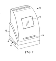
図1は例示的生物成長プレートスキャナ10の斜視図である。図1に示すように、生物成長プレートスキャナ10は生物成長プレート(図1には図示せず)を受け取る引出し14を有するスキャナユニット12を含んでいる。引出し14は生物成長プレートを走査・分析のために生物成長プレートスキャナ10内に移動させる。
FIG. 1 is a perspective view of an exemplary biological
また生物成長プレートスキャナ10は表示画面16を含み、生物成長プレートの分析の進行または結果をユーザに表示し得る。代替的または追加的に、表示画面16は生物成長プレートスキャナ10により走査された成長プレートの画像をユーザに提示し得る。表示された画像は光学的に拡大またはデジタルに拡大し得る。
The biological
載置台18は生物成長プレートスキャナ10による分析後、成長プレートを排出することができる排出スロット20を画定している。従って生物成長プレートスキャナ10はスキャナユニット12が載置台18に載置されている2部構成を有し得る。2部構成は例示目的で図1に図示されているが、本明細書に記載された発明に必要としたりまた発明の限定を意図するものではない。
The mounting table 18 defines a
スキャナユニット12は生物成長プレートを走査して画像を生成するための撮像装置を収容している。撮像装置は単色ラインスキャナまたはエリアスキャナの形状を取り、生物成長プレートの前面および/または背面照明を提供する多色照明システムと組み合わせて設けてもよい。さらにスキャナユニット12は例えば成長プレート内の生物剤の数または量を判定するために、走査画像の分析を行う処理ハードウェアを収容し得る。例えば引出し14を介して生物成長プレートが提示されると、プレートを走査用光学プラテンに隣接して配置し得る。
The
その後引出し14が開放されると、成長プレートは載置台18内に下降して排出スロット20を介して排出し得る。そのため載置台18は成長プレートを排出スロット20を介して生物成長プレートスキャナ10から排出するコンベヤーを収容し得る。生物成長プレートが引出し14内に挿入され、スキャナユニット12内に移動され、走査された後、生物成長プレートは載置台18内に下降し、そこで移動ベルトなどの水平コンベヤーがスロット20を介してプレートを排出する。
Thereafter, when the
図2は生物成長プレートスキャナ10の他の斜視図である。図2に示すように引出し14は生物成長プレートスキャナ10から外側に延出して生物成長プレート22を受け取る。図示のように生物成長プレート22を引出し14内に設けられた台24上に配置し得る。いくつかの実施形態において台24はカムレバーなどの位置決め作動装置を含み、台を上昇させて成長プレート22を生物成長プレートスキャナ10内に正確に位置決めし得る。生物成長プレート22を台24上に配置すると、引出し14はスキャナユニット12内に後退して生物成長プレートを走査位置、すなわち生物成長プレートが光学的に走査される位置に配置する。
FIG. 2 is another perspective view of the biological
図3および4は例示的生物成長プレート22の正面図である。一例として適当な成長プレート22は、商品名ペトリフィルム(PETRIFILM)プレートでスリーエム(3M)により販売されている生物成長プレートを含み得る。代替的には生物成長プレート22は、特定の細菌または他の生物剤を成長させる他の生物成長培地を含み得る。いくつかの実施形態において生物成長プレート22は、成長プレートに関連する生物培地のタイプの自動識別を容易にするプレートタイプ標識28を担持している。
3 and 4 are front views of an exemplary
プレートタイプ標識28は機械可読である符号化パターンを提示する。図3および4の例において、プレートタイプ標識28は光学的読取可能パターンの形状を取る。具体的には図3および4は、生物成長プレート22の角部余白に形成された明暗四分の一区分の4つの正方形パターンを示す。換言すればプレートタイプ標識28は、符号化パターンを形成する白黒間で変化させたセルの二次元格子を画定する。
The
文字、バーコード、二次元バーコード、光学格子、ホログラム等などの多様な光学パターンが考えられる。さらにいくつかの実施形態において、プレートタイプ標識28は磁気的または無線技術により読取可能なパターンの形状を取り得る。代替的にはプレートタイプ標識28は、光学的または機械的技術により読取可能なアパーチャ、スロット、表面輪郭等の形状を取り得る。いずれの場合もプレートタイプ標識28は生物成長プレートスキャナ10による生物成長プレート22のタイプの自動識別を可能にする十分な情報を担持している。
Various optical patterns such as characters, barcodes, two-dimensional barcodes, optical gratings, holograms, and the like are conceivable. Further, in some embodiments, the
生物成長プレートは例えば好気性細菌、大腸菌、大腸菌型、腸内細菌科、酵母菌、糸状菌、黄色ブドウ球菌、リステリア菌、およびカンピロバクター菌等を始めとする細菌または他の生物剤の迅速な成長ならびに検出および測定を容易にし得る。ペトリフィルム(PETRIFILM)プレートまたは他の成長培地を利用することにより食品試料の細菌試験を単純化することができる。また生物成長プレートスキャナ10は、自動プレートタイプ検出および検出されたプレートタイプに基づいた画像処理プロファイルの自動選択を提供し、生物成長プレート22を例えばプレートの画像上の細菌コロニーを計数して分析することにより、このような試験をさらに単純化することができる。
Biological growth plates are for rapid growth of bacteria or other biological agents, including aerobic bacteria, E. coli, coliforms, Enterobacteriaceae, yeasts, filamentous fungi, Staphylococcus aureus, Listeria monocytogenes, and Campylobacter As well as detection and measurement. Utilizing a Petrifilm plate or other growth media can simplify the bacterial testing of food samples. The biological
図3に示すように生物成長プレート22は成長エリア26を画定している。細菌コロニー数に関して、プレート22内で試験されている所与の試料が許容可能か否かの判定は単位面積当たりの細菌コロニーの数による。従ってスキャナ10はプレート22上の単位面積あたりの細菌コロニーの量を定量し得るとともに、その量すなわち「数」を閾値と比較し得る。生物成長プレート22の表面は、1つ以上のタイプの細菌または他の生物剤の迅速な成長を容易にするように構成された1つ以上の成長促進剤を含み得る。
As shown in FIG. 3, the
成長エリア26内の生物成長プレート22の表面上に、概して液状の被験材料の試料を配置した後、プレート22を培養室(図示せず)に挿入することができる。培養室において、図4の生物成長プレート22に示すように成長プレート22により成長する細菌コロニーまたは他の生物剤が出現する。図4の生物成長プレート22上の様々なドット30で表されるコロニーはプレート22上に異なる色で出現し、スキャナ10による細菌コロニーの自動検出および測定を容易にする。
After placing a generally liquid sample of the test material on the surface of the
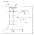
図5は生物成長プレートスキャナ10の内部動作を図示するブロック図である。図5に図示するように、生物成長プレート22は生物成長プレートスキャナ10の内部で台(図5では図示せず)上に配置される。台は生物成長プレート22を撮像装置32の所望の焦点面に配置する。本発明によれば撮像装置32は成長プレート22の前面および背面照明用の多色照明システム、および成長プレート22の表面の画像を取り込む単色ラインまたはエリアスキャナを含み得る。いくつかの実施形態において例えば撮像装置32は二次元単色カメラの形状を取り得る。
FIG. 5 is a block diagram illustrating the internal operation of the biological
一般に撮像装置32は、生物成長プレートを1色以上の異なる照明色で照明中に生物成長プレート22または少なくとも生物成長プレート内の成長領域の画像を取り込む。いくつかの実施形態において、異なる生物成長プレートの要件に従って照明継続時間および照明強度を制御し得る。さらに異なる生物成長プレートの要件に従って生物成長プレートの第1および第2の側の選択的照明を制御し得る。
In general, the
プロセッサ34は撮像装置32の動作を制御する。動作中、プロセッサ34は撮像装置32を制御して生物成長プレート22を異なる照明色で照明するとともに、生物成長プレート22の画像を取り込む。プロセッサ34は各異なる照明色で照明中に撮像装置32から走査画像を表わす画像データを受け取るとともに、画像を合成して多色合成画像を形成する。プロセッサ34は生物成長プレート22の合成画像を分析するとともに、画像を分析してコロニー数または有無の結果などの分析結果を生成する。
The
実施形態によってはプロセッサ34は画像の一部分を抽出または分離してプレートタイプ標識28を隔離し得る。プロセッサ34は例えばマシンビジョン技術を利用してプレートタイプ標識28を分析し、生物成長プレート22に関連するプレートタイプを識別する。そしてプロセッサ34は画像処理プロファイルメモリ36から画像処理プロファイルを検索する。画像処理プロファイルは検出されたプレートタイプに対応しており、画像取込条件および画像分析条件を特定し得る。プロセッサ34はマイクロプロセッサ、デジタル信号プロセッサ、アプリケーション特定用途向け集積回路(ASIC)、フィールド・プログラマブル・ゲート・アレイ(FPGA)または本明細書に記載されているような機能性を提供するようにプログラムまたは構成された他の集積または個別論理回路の形状を取り得る。
In some embodiments, the
プロセッサ34は画像処理プロファイルを利用して適正な画像処理パラメータを読み込むとともに生物成長プレート22の走査画像を処理するように進行する。このようにプロセッサ34は生物成長プレート22から得られた画像データを処理するという意味で画像処理装置をなす。画像処理パラメータは画像処理プロファイルおよび検出されたプレートタイプとともに変化して、走査画像の分析に対して色、サイズ、形状および近接基準などのパラメータを始めとする特定の撮像装置分析条件を指定し得る。基準は被分析プレート22のタイプにより異なるとともに、生物成長プレートスキャナ10により生成されるコロニー数または他の分析結果に大きく影響し得る。また画像処理プロファイルは、特定の生物成長プレートのタイプに適した照明色、強度、継続時間などの画像取込条件を指定し得る。
The
適切な画像処理パラメータを選択すると、プロセッサ34は走査画像を処理するとともに、ディスプレイ16を介してユーザに提示されるコロニー数または有無の結果などの分析結果を生成する。またプロセッサ34は後にスキャナ10から検策するために、分析結果をカウントデータメモリ38などのメモリに記憶する。カウントデータメモリ38に記憶されたデータは例えば通信ポート40、例えばユニバーサルシリアルバス(USB)ポートを介して生物成長プレートスキャナ10と通信しているホストコンピュータによって検索し得る。ホストコンピュータは、分析のために生物成長プレートスキャナ10に提示される一連の生物成長プレート22に対する分析結果をコンパイルし得る。
Upon selection of the appropriate image processing parameters, the
生物成長プレートスキャナ10内の画像処理プロファイルの自動選択は、適当な画像処理プロファイルを選択するための便利で精度の高い技術を提供することができる。画像処理プロファイルの自動選択は細菌コロニー計数および他の分析手順の精度を向上させることができる。特に自動画像処理プロファイル選択により技術者がプレートタイプを目視で識別して手動で入力する必要性をなくすことができる。このようにして人間の介入に関連する場合もあるプレート識別エラーをなくすことができる。その結果、スキャナ10とプレートタイプ標識28を担持する生物成長プレート22とを組み合わせると、効率および実験技術者の作業フローを向上させることができる一方、分析精度、そして最終的には食品安全性および人間の健康を高めることができる。
Automatic selection of an image processing profile within the biological
図6は図5の生物成長プレートスキャナ10をより詳細に図示するブロック図である。生物成長プレートスキャナ10の撮像装置32(図5)は図6に示すようにカメラ42と、前面照明部品44と背面照明部品46と、を含み得る。本発明によれば前面および背面照明システム44、46は選択的に異なる照明強度、色および継続時間を生じ得る。具体的にはプロセッサ34は前面および背面照明システム44、46を制御して生物成長プレート22を異なる照明色、強度および継続時間で露光する。さらにプロセッサ34はカメラ42を制御して異なる色での照明中に生物成長プレート22の画像を取り込む。
FIG. 6 is a block diagram illustrating the biological
例えばプロセッサ34は照明システム44、46およびカメラ42を協調制御して生物成長プレート22の多数の画像を取り込む。プロセッサ34はその後その多数の画像を合成して多色合成画像を形成する。プロセッサ34はその多色合成画像および/または合成画像の個々の成分を用いて生物成長プレート22を分析して、検出またはコロニー数などの分析結果を生成する。一実施形態において、前面および背面照明システム44、46はプロセッサ34の制御下で生物成長プレート22を選択的に赤色、緑色、および/または青色の照明色に露光する。この例においてカメラ42は生物成長プレート22の赤色、緑色、および青色の画像を取り込む。そしてプロセッサ34は赤色、緑色、および青色の画像を合成して分析用の多色合成画像を形成する。
For example, the
例証として、プロセッサ34はまず前面および背面照明部品44、46内の赤色照明源を作動させて、生物成長プレート22を赤色照明に露光する。具体的にはプロセッサ34は赤色照明源の強度および継続時間を制御し得る。赤色照明露光と同期してカメラ42が生物成長プレート22の赤色画像を取り込んでその取込画像をスキャナ10内の画像メモリ47に記憶する。
Illustratively, the
そしてプロセッサ34は前面および背面照明部品44、46内の緑色照明源を作動させて、生物成長プレート22を緑色照明に露光し、その後カメラ42が緑色画像を取り込む。同様にプロセッサは前面および背面照明部品44、46内の青色照明源を作動させて、生物成長プレート22を青色照明に露光し、その後カメラ42が青色画像を取り込む。
The
カメラ42は赤色、緑色および青色照明露光の各々に対して単色化像を取り込むとともに、その画像を別個のファイルに記憶し得る。プロセッサ34はそのファイルを用いて取込画像を合成し、分析用の合成画像を形成する。生物成長プレート22が多数の照明色に露光される順序は変更可能である。そのため赤色、緑色および青色照明源への順次露光は本発明を制限するものとは考えるべきものではない。
カメラ42によって取り込まれた個々の画像は光学強度または光学濃度に関して表される。換言すればカメラ42は、各露光チャネル、例えば赤色、緑色および青色に対する生物成長プレート22の反射出力を定量化するのに用いることが可能な階調データを取り込む。個々の画像を取り込むために単色カメラ42を用いることは画像解像度便益およびコスト削減に繋がる。特に安価な単色カメラ42は、同時に赤色、緑色および青色スペクトルを取り込む多色カメラに比べて高い空間分解能を提供し得る。従ってカメラ42は低コストで生物成長プレート22を効果的に分析するのに必要な高解像度画像を得ることができる。単色カメラ42は1つの多色画像を得るのではなく、多数の高解像度画像、例えば赤色、緑色および青色を取り込み、プロセッサ34はそれらを合成して高解像度の多色画像を生成する。
Individual images captured by the
前面および背面照明システム44、46内の異なる照明源はLEDの形状を取り得る。具体的には異なる照明色は独立した各組のカラーLED、例えば赤色、緑色および青色LEDにより達成できる。利点としてはLEDはランプなどの他の照明源と比べて寿命が長い。またLEDは本来的に出力ばらつきのないスペクトルを提供するとともに光出力を安定化し得る。
Different illumination sources in the front and
またプロセッサ34はLEDの出力強度および露光継続時間を容易に制御して、適当なレベルの照明で生物成長プレート22の連続照明を行うことができる。プロセッサ34を異なる組のカラーLEDを独立して制御するようにプログラムすることにより、生物成長プレート22に照射される各照明色に対して異なる出力強度および露光継続時間を提供することができる。
In addition, the
LEDが異なる輝度特性を示すとともに、LEDに関連する反射板ハードウェアまたは他の光学部品が非均一性を提示する場合があるため、プロセッサ34を介してLEDを独立して制御する能力は有利である。さらにカメラ42および1つ以上の付随カメラレンズは照明色に対して異なる応答を示す場合がある。例えばカメラ42は赤色、緑色および青色に対する感応程度が異なり、所与の照明チャネルに対する色応答でさらに非均一性を示す場合がある。
The ability to independently control the LEDs via the
しかしながらプロセッサ34はLEDを独立制御してこのような非均一性を補償することができる。例えばスキャナ10は工場または現場でカメラ42の応答性を異なる照明源に対して特徴付けるように較正し、その後プロセッサ34が適用する適正な駆動値を記憶することによりその応答性を補償し得る。そのためプロセッサ34は、異なる照明色および強度レベルに対して異なる駆動値をLEDに適用し、カメラ42によって取り込まれた画像の所望程度の均一性を生じ得る。
However,
実施形態によってはスキャナ10は異なる画像処理プロファイルに従って異なる生物成長プレート22の画像を処理し得る。画像処理プロファイルは、ユーザ入力またはスキャナ10に提示される生物成長プレート22のタイプの識別に基づいてプロセッサ34により選択し得る。画像処理プロファイルは、特定のプレートタイプの画像を取り込むための照明強度、露光継続時間、および色などの特定の画像取込条件を指定し得る。こうしてスキャナは、異なる生物成長プレート22の画像を処理する際に異なる照明条件を始めとする異なる画像取込条件を適用し得る。
In some embodiments, the
例証として生物成長プレート22のタイプによっては特定の色、強度および継続時間の照明を必要とする場合がある。さらに生物成長プレート22によっては両方ではなく前面または背面照明しか必要としない場合がある。例えば好気性細菌数プレートは前面照明且つ赤色などの単一色のみによる照明しか必要としない。また大腸菌/大腸菌型プレートは背面照明且つ赤色と青色照明の組み合わせしか必要としない。同様に特定の強度レベルおよび継続時間が適正であり得る。これらの理由でプロセッサ34は画像処理プロファイルにより指定された画像取込条件に応じて照明を制御し得る。
Illustratively, certain types of
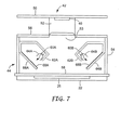
図7は生物成長プレートスキャナ10用の前面照明部品44を図示する側面図である。図7に示すように前面照明部品44はカメラ42と一体化し得る。例えばカメラ42はカメラ本体を含み、CMOSまたはCCDカメラチップ48が、カメラチップ48を駆動するとともにプロセッサ34用の画像データを受け取る回路を担持し得るプリント回路基板などのカメラ背面50に搭載されている。カメラレンズ52は、前面照明部品44により画定される筐体内のアパーチャ53を介して生物成長プレート22の画像を取り込むように配向し得る。図7の例では前面照明部品44は側壁54と、前面壁56と、光学プラテン58と、を含む。光学プラテン58は単に、照明光の透過およびカメラ42による生物成長プレート22の画像の取込を可能にするガラスまたはプラスチックの透明なシートであり得る。実施形態によっては光学プラテン58をなくして、プレート22の成長エリア26が成長エリア26と発光との間に構造物を挟まずに照明されるようにすることができる。生物成長プレート22を持ち上げて光学プラテン58と接触または近接させることによりカメラ42が画像を取り込むことができるようにし得る。
FIG. 7 is a side view illustrating the
多数の部品を前面照明部品44内に収容し得る。例えば前面照明部品44は、生物成長プレート22の成長エリア26の周囲に直線配列で好適に配置した1つ以上の照明源60A、60Bを含み得る。具体的には赤色、緑色および青色照明源60A、60Bの直線配列は生物成長プレート22の4つの縁部の各々に沿って、例えば正方形パターンで延在し得る。他の実施形態では照明源を代替パターン、例えば円形パターンで配置し得る。また照明源60A、60BはLEDの形状を取り得るとともに、1個の赤色、1個の緑色および1個の青色LEDの群で配置し得る。
A number of components may be housed within the
照明源60A、60Bは照明室62A、62B内に載置し得る。反射カウル64A、64Bが照明源60A、60Bの周囲に載置されて、室62A、62Bの内部に延在する壁66A、66Bに向かって照明源による発光を反射して集光する役目を果たす。反射材を反射カウル64A、64Bの内面に塗布、堆積または接着剤で貼り付け得る。反射カウル64A、64Bに適した反射材の例は、ミネソタ州セントポールのスリーエム・カンパニー(3M Company(St.Paul,Minnesota))から市販されている、スリーエム・ラジアント・ミラー・リフレクタ(3M Radiant Mirror Reflector)VM2000である。
The
壁66A、66Bは照明源60A、60Bから受け取った光を拡散する役割を果たす光拡散膜68A、68Bなどの拡散材を担持し得る。拡散光は前面照明部品44の内部室内に透過して生物成長プレート22の成長領域26を照明する。拡散膜68A、68Bに適した拡散材の例は、ニューヨーク州ニューヨークのミツイアンドカンパニー・インコーポレーション(Mitsui&Co.,Inc.(New York,New York))から市販されているミツイ(Mitsui)WS−180A拡散白色膜である。拡散膜68A、68Bは壁66A、66Bの内面に塗布または接着剤で添付し得る。
The
図8は前面照明部品44をさらに詳細に図示する正面図である。図8に示すように、前面照明部品44は生物成長プレート22の周囲に配置された4つの照明室62A、62B、62C、62Dを含み得る。各照明室62は2組の照明源60を含み得る。例えば室62Aは照明源60A、60Cを含み、室62Bは照明源60B、60Dを含み、室62Cは照明源60E、60Fを含み、室62Dは照明源60G、60Hを含み得る。さらに室62A、62B、62C、62Dは拡散膜を担持するそれぞれの壁66A、66B、66C、66Dを含み得る。他の実施形態では各室62は任意の数の照明源60を含み、その数は他の室の照明源の数と同じでも同じでなくてもよい。
FIG. 8 is a front view illustrating the
照明源60は例えば3個ずつの群にグループ化された一連の照明要素を含み得る。具体的には各照明源60は赤色LED、緑色LEDおよび青色LEDを含み、これらは別々に作動して生物成長プレート22を照明することができる。個々のLEDが作動されると、前面照明部品44により画定される内部室は拡散光で満たされて生物成長プレート22に前面照明を提供する。カメラ42は各異なる照明色での連続露光周期中に生物成長プレート22の画像を取り込む。
The illumination source 60 may include a series of illumination elements grouped, for example, in groups of three. Specifically, each illumination source 60 includes a red LED, a green LED, and a blue LED, which can operate separately to illuminate the
図9は装填位置、すなわち生物成長プレート22が最初にスキャナに装填される位置の生物成長プレートスキャナ10用の背面照明部品46を図示する側面図である。実施形態によっては生物成長プレート22を図2に示すように引出し14を介してスキャナに装填し得る。具体的には引出し14は生物成長プレート22用の台としての役目を果たす拡散要素74を担持している。引出し14は生物成長プレート22をスキャナ10の内部に後退させ、生物成長プレートを走査位置に上昇させることができるように構成し得る。
FIG. 9 is a side view illustrating the
一旦装填すると、生物成長プレート22を光拡散要素74により支持または代替的には光拡散要素に近接した透明な台により支持することができる。光拡散要素74は拡散要素に横方向に注入された光を拡散してその光を上方に放射することにより生物成長プレート22の背面照明を提供する役目を果たす。背面照明部品46はスキャナ10内の空間を維持しつつ良好な均一性で生物成長プレート22の背面を効果的に照明する。
Once loaded, the
さらに背面照明部品46は使用中に移動する必要のない1組の固定照明源76A、76Bを搭載することにより、電気配線に対する労苦を軽減するとともに環境汚染物に対して曝されることも少なくなる。より正確に言えば生物成長プレート22および拡散要素74を固定照明源76A、76Bと一直線になる位置に上昇させる。つまり背面照明部品46は、生物成長プレート22の表面にわたる良好な照明均一性、平坦な照明表面、照明源76A、76Bの固定配置、および空間維持のための効率的なサイズおよび容積をもたらす。
Furthermore, the
照明源76A、76Bは、拡散要素が上昇した走査位置にあるとき拡散要素74の横方向縁部に隣接して配置される。各照明源76A、76Bは反射カウル78A、78Bを含み、照明源により発光された光を拡散要素74のそれぞれの縁部に向かって反射して集光し得る。このようにして照明源76A、76Bは光拡散要素74に光を注入する。反射材を反射カウル78A、78Bの内面に塗布、堆積または接着剤で貼り付け得る。反射カウル78A、78Bに適した反射材の例は、ミネソタ州セントポールのスリーエム・カンパニー(3M Company(St.Paul,Minnesota))から市販されている、スリーエム・ラジアント・ミラー・リフレクタ(3M Radiant Mirror Reflector)VM2000である。
The illumination sources 76A, 76B are positioned adjacent to the lateral edges of the diffusing
プラテン支持部80A、80Bを設けて光学プラテン58(図7)を支持するとともに、背面照明部品46を前面照明部品44と係合するインターフェースを提供し得る。図9にさらに示すように、支持ブラケット82A、82Bは光拡散要素74用の載置台を提供する。さらに照明源76A、76Bは照明源を駆動するのに必要な回路の一部を担持する背面84A、84Bに載置されている。しかし背面84A、84Bおよび照明源76A、76Bは通常固定されているため照明源の移動ならびに配線および他の電気部品に関連する労苦は必然的ではなく、さらに環境汚染物に対して曝されることが少なくなる。
Platen supports 80A, 80B may be provided to support the optical platen 58 (FIG. 7) and provide an interface for engaging the
拡散要素74の背面側は照明源76A、76Bから受け取った光の内部反射、すなわち拡散要素により画定される内部室内への光の反射を促進する反射膜88により画定し得る。このように光は拡散要素74の背面領域を出射せずに生物成長プレート22に向かって内側および上側に反射される。反射膜88は拡散要素74により画定される壁に塗布、堆積または接着剤で貼り付け得る。代替的には反射膜88は独立しており拡散要素74の背面壁を画定し得る。反射膜88に適した材料の例は、ミネソタ州セントポールのスリーエム・カンパニー(3M Company(St.Paul,Minnesota))から市販されている、スリーエム・ラジアント・ミラー・フィルム(3M Radiant Mirror Film)2000F1A6である。
The back side of the diffusing
生物成長プレート22に隣接する拡散要素74の前面側は光学導光・拡散膜86などの光拡散材を担持し得る。拡散要素74は反射膜88と、光学導光・拡散膜86と、照明源76A、76Bに隣接した側壁をなすそれぞれの光透過層89A、89Bとの間に内部室を画定し得る。以下に説明するように照明源76A、76Bに隣接していない光拡散要素74の対向側壁は反射層により形成されて、拡散要素内に注入された光の内部反射を促進し得る。
The front side of the
光拡散要素74により画定される内部室は単に空であり空気で満たされている。光学導光・拡散膜86は拡散要素74から射出された光を生物成長プレート22に向かって拡散する役目を果たす。好適な光拡散膜の例は、30%の被覆面積を有する拡散白色ドット(diffuse white dots)のパターンで印刷されている、スリーエム・オプティカル・ライティング・フィルム(3M Optical Lighting Film)であり、プリズム配向が拡散要素に向かって下方に向いている。具体的には光学導光・拡散膜86のプリズムが拡散要素74内に向いているとともに、プリズムの配向が概して照明源76A、76Bに垂直である。スリーエム・オプティカル・ライティング・フィルム(3M Optical Lighting Film)がミネソタ州セントポールのスリーエム・カンパニー(3M Company(St.Paul,Minnesota))から市販されている。
The interior chamber defined by the
さらに拡散要素74は光学導光・拡散膜86上に耐傷性光透過層87を含み得る。生物成長プレート22を耐傷層87と接して配置し得る。さらなる耐傷性光透過層89A、89Bを拡散要素74の横縁部に隣接して配置し得る。具体的には層89A、89Bを照明源76A、76Bと拡散要素74との間に配置し得る。
Further, the diffusing
耐傷性光透過層89A、89Bは拡散要素74と反対側の光入射スロット上に配置されて照明源76A、76Bの光を拡散要素を透過させるとともに、拡散要素の上方および下方への摺動用の耐久面を提供する。層87、89A、89Bのいずれかに用いるのに適した耐傷性光透過材の例は、アクリルガラスまたはアクリルプレートと称されることもあるアクリル製ガラス状材料に属する。代替的には層87、89A、89Bはガラスで形成し得る。
The scratch-resistant light-transmitting
層87としてのアクリルまたはガラスプレートを用いて生物成長プレート用の安定した清浄化可能な台を提供するとともに、拡散要素74を損傷から保護することができる。およそ1mmの間隙を層87と光学導光・拡散膜86との間に設けることにより拡散膜の光学性能を保持することができ、空気以外の材料との接触に変更することもできる。
An acrylic or glass plate as
図10は走査位置にある図9の背面照明部品46を図示する側面図である。具体的には図10において拡散要素74が図9に図示した位置に対して上昇されている。拡散要素74をカム、リードスクリューまたは滑車装置などの様々な上昇機構によって上昇し得る。拡散要素74を走査位置に上昇させると、生物成長プレート22は光学プラテン58(図7)に近接または接触する。
FIG. 10 is a side view illustrating the
走査位置に上昇すると、照明源76A、76Bは拡散要素74に光を注入し、拡散要素74はその光を拡散するとともに上方に向けることにより生物成長プレート22に対して背面照明を提供する。以下に説明するように照明源76A、76Bは異なる着色照明部品を搭載し、これらの部品が選択的に作動されることによりカメラ42が各色、例えば赤色、緑色および青色に対して単色画像を分離し得る。
When raised to the scanning position, the
図11は図9および図10の背面照明部品46を図示する底面図である。図11に示すように、多数の照明源76A〜76Hを拡散要素74の対向側に直線配列で配置し得る。図11は生物成長プレート22の反対側からの背面照明部品の透視図を提供するため、反射層88を示す。各照明源76は3つの照明要素、例えば赤色(R)要素、緑色(G)要素、および青色(B)要素を含み得る。赤色、緑色および青色要素は赤色、緑色および青色LEDであり得る。背面照明部品46は赤色要素がすべて同時に作動されて生物成長プレート22の背面側を赤色光で照明することによりカメラ42で赤色の画像を取り込めるように構成し得る。緑色要素および青色要素もそれぞれ同様に同時に作動し得る。
FIG. 11 is a bottom view illustrating the
図11にさらに示すように反射層93A、93Bは照明源76に隣接しない側に拡散要素74の対向側壁を形成する。反射層93A、93Bは反射層88と同様な材料で形成するとともに、内部またはそれぞれの側壁に貼り付けるか、またはそれ自体で独立壁を形成し得る。一般には反射層88、93A、93Bは照明源76から注入された光を拡散要素74により画定される内部室内に反射する役目を果たし、光が拡散要素の背面または側壁から逃げないようにする。むしろ光を内部におよび拡散材86に向かって反射する。このように光を集光してその後拡散材86によって拡散して透過させることにより生物成長プレート22の背面側を照明する。
As further shown in FIG. 11, the reflective layers 93 </ b> A and 93 </ b> B form opposing side walls of the diffusing
図12は生物成長プレートスキャナ10に対する前面および背面照明部品44、46ならびにカメラ42の組み合わせを図示する側面図である。図12に示すように光学プラテン58は前面照明部品44と背面照明部品46との間のインターフェースとしての役目を果たす。動作中、生物成長プレート22は上昇されて光学プラテン58に近接してまたは接触する。そして前面および背面照明部品44、46は生物成長プレート22を選択的に異なる照明色で露光することにより、カメラ42は生物成長プレートの画像を取り込むことができる。例えば前面および背面照明部品44、46は赤色、緑色および青色LEDを順に選択的に作動して生物成長プレート22の赤色、緑色および青色画像を形成し得る。
FIG. 12 is a side view illustrating the combination of front and
図13は照明システム用の制御回路90を図示する回路図である。制御回路90を用いて前面および背面照明部品44、46内の照明源を制御し得る。図7〜12の例では前面および背面照明部品44、46は各々8個の別々の照明源60、76を含んでいる。各照明源60、76は赤色、緑色および青色照明要素、例えば赤色、緑色および青色LEDを含んでいる。従って図13は8個の異なるLEDを選択的に同時に駆動するように搭載された例示的制御回路90を図示している。このように制御回路90はすべての赤色LEDを選択的に作動して生物成長プレート22を赤色光で照明し得る。同様に制御回路90はそれぞれすべての緑色および青色照明用緑色または青色LEDを選択的に作動し得る。図13は、8個のLEDを同時に制御しているため前面照明部品44または背面照明部品46のいずれかを制御している制御回路90を示す。しかしプロセッサ34により制御される出力回路は基本的に二重にし得るため、16個のLED、従って前面照明部品44および背面照明部品46を同時に制御することができる。
FIG. 13 is a circuit diagram illustrating a
図13に示すようにプロセッサ34はデジタル出力値を生成して1組のLEDを駆動する。デジタル−アナログ変換機(DAC)91A〜91Hはデジタル出力値をアナログ駆動信号に変換する。バッファ増幅器92A〜92HはDAC91A〜91Hによって生成されたアナログ信号を増幅し、その増幅したアナログ駆動信号をLED94A〜94H、96A〜96H、98A〜98Hの各アレイに印加する。DAC91A〜91Hおよび増幅器92A〜92Hはプログラム可能なコントローラとして機能してLED94A〜94H、96A〜96H、98A〜98Hの照明継続時間および照明強度を選択的に制御する。プロセッサ34は、スキャナ10により処理される異なる生物成長プレート22の要件に従って、コントローラすなわちDAC91A〜91Hおよび増幅器92A〜92Hを駆動する。
As shown in FIG. 13, the
プロセッサ34は特定の組のデジタル出力値にアクセスして、LED94A〜94H、96A〜96H、98A〜98Hに対する所望の出力強度を生じるため有利である。例えばデジタル出力値は、様々なLED94A〜94H、96A〜96H、98A〜98Hにより提供される照明の均一性を向上させるようにスキャナ10の工場または現場較正時に決定することができる。また赤色、緑色および青色LEDを異なる出力強度および応答性により特徴付け得るとともに、関連する反射板および光学ハードウェアが非均一性を提示して、プロセッサ34による独立制御をいくつかの用途において望ましいものにし得る。
The
またデジタル出力値を異なる生物成長プレート22の要件に基づいて、すなわち成長プレートに照射する照明の強度および継続時間を制御するように決定し得る。従ってプロセッサ34はスキャナ10に提示される生物成長プレート22の特定のタイプに基づいて、異なる継続時間に対して異なる出力値を選択的に生成し、異なる組のLED94A〜94H、96A〜96H、98A〜98Hを有効にし、さらに前面照明、背面照明、またはその両方のいずれかを選択的に有効にし得る。
The digital output value can also be determined based on the requirements of different
すべてのLED94A〜94H、96A〜96H、98A〜98Hのアノードは、選択されたLEDを同時に作動させるための駆動増幅器92A〜92Hのそれぞれの出力に結合されている。特定の照明色用のLEDの選択的作動を可能にするため、LED94A〜94H(赤色)のカソードはスイッチ、例えばエミッタが接地電位に結合されたバイポラー接合トランジスタ100Aのコレクタに共通結合されている。同様にLED96A〜96H(緑色)のカソードはバイポラー接合トランジスタ100Bのコレクタに共通結合されており、LED98A〜98H(青色)のカソードはバイポラー接合トランジスタ100Cのコレクタに共通結合されている。
The anodes of all
プロセッサ34は赤色イネーブル、緑色イネーブルまたは青色イネーブル信号で各バイポラートランジスタ100A〜100Cのベースを駆動する。動作中、生物成長プレートを赤色照明に露光するためにプロセッサ34は赤色LED94A〜94Hに対するデジタル値を選択するとともにそのデジタル値を、バッファ増幅器92A〜92Hによって増幅用のアナログ駆動信号を生成するDAC91A〜91Hに印加する。赤色LED94A〜94Hに対するデジタル値の印加と同期して、プロセッサ34は赤色イネーブル線を作動させてトランジスタ100Aにバイアスをかけて「オン」にすることにより赤色LED94A〜94Hのアノードを接地させる。
The
プロセッサ34はイネーブル線を用いて赤色LED94A〜94Hを選択的に作動することにより生物成長プレート22を赤色照明に露光させることができる。同時にプロセッサ34はカメラ42を制御して生物成長プレート22の赤色画像を取り込む。緑色および青色画像を取り込むために、プロセッサ34は適当なデジタル駆動値を生成してそれぞれ緑色イネーブルおよび青色イネーブル線を作動させる。利点としてはイネーブル線を用いることにより照明色の露光継続時間を独立して制御することができる。例えば生物成長プレート22を異なる継続時間の赤色、緑色および青色照明に露光することが望ましい。
The
図14はプレートカウントを生じるための合成画像準備用の多色画像の取り込みを図示する機能ブロック図である。図14に示すように、単色カメラ42は生物成長プレート22から赤色画像102A、緑色画像102Bおよび青色画像102Cを取り込む。そしてプロセッサ34は赤色、緑色および青色画像102を処理して合成画像104を生成する。さらにプロセッサ34は合成画像を処理してコロニー数106などの分析結果を生成する。赤色、緑色および青色画像を合成した合成画像が準備されると、プロセッサ34は従来の画像分析技術を適用してコロニー数を生成する。
FIG. 14 is a functional block diagram illustrating the capture of a multi-color image for preparing a composite image to produce a plate count. As shown in FIG. 14, the
図15はプレートカウントを生じるための合成画像準備用の多色画像を取り込む技術を図示するフロー図である。図15に示すようにこの技術は生物成長プレート22を異なる照明色で選択的に照明するステップ(108)と、各照明色への露光中にプレート画像を取り込むステップ(110)と、を含んでいる。この技術は照明色毎の個別取込画像に基づいて合成画像を形成するステップ(112)と、合成画像を処理(114)してコロニー数などの分析結果を生成するステップ(116)と、をさらに含んでいる。コロニー数はユーザに表示されるとともにデータファイルに記録される。前述したようにいくつかの画像を取り込む技術は、スキャナ10により処理される特定の生物成長プレート22の要件によって1つ、2つまたはそれ以上の照明色、さらに前面側照明、背面側照明またはその両方での照明を含み得る。
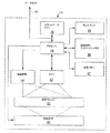
FIG. 15 is a flow diagram illustrating a technique for capturing a multicolor image for preparing a composite image for generating a plate count. As shown in FIG. 15, the technique includes selectively illuminating the
図16は図15の技術をより詳細に図示するフロー図である。図16に示すように動作中、プロセッサ34はまずデジタル値を出力して赤色照明LED94A〜94H(図13)を駆動する(118)とともに、赤色イネーブル線で前面および背面赤色照明LEDを作動して(120)生物成長プレート22を照明する。そして赤色LED94A〜94Hによる照明中にカメラ42が生物成長プレート22の画像を取り込む(122)。
FIG. 16 is a flow diagram illustrating the technique of FIG. 15 in more detail. During operation as shown in FIG. 16, the
次にプロセッサ34はデジタル値を出力して緑色照明LED96A〜96Hを駆動する(124)とともに、緑色イネーブル線で前面および背面緑色照明LEDを作動して(126)生物成長プレート22を照明する。そして緑色照明LED96A〜96Hによる照明中にカメラ42が生物成長プレート22の画像を取り込む(128)。その後プロセッサ34はデジタル値を出力して青色照明LED98A〜98Hを駆動する(130)とともに、青色イネーブル線で青色照明LEDを作動する(132)。
The
青色画像がカメラ42で取り込まれた(134)後、プロセッサ34は赤色、緑色および青色画像を合成して合成赤色−緑色−青色画像を形成する(136)。そしてプロセッサ34は合成赤色−緑色−青色画像を処理して(138)および/または合成画像の個々の成分を処理してコロニー数を生成する(140)。また実施形態によってはプロセッサ34は赤色、緑色および青色画像を合成して合成画像を形成する前に、個々の赤色−緑色−青色画像を処理し得る。また照明および取込の赤色−緑色−青色順は本明細書において例示目的で記載している。従って生物成長プレート22は異なる順で照明および走査し得る。
After the blue image is captured by the camera 42 (134), the
動作中、プロセッサ34はコンピュータ読取可能媒体に記憶され得る命令を実行して、本明細書に記載されたプロセスを行う。コンピュータ読取可能媒体は、同時性ダイナミックランダムアクセスメモリ(SDRAM)などのランダムアクセスメモリ(RAM)、読み出し専用メモリ(ROM)、不揮発性ランダムアクセスメモリ(NVRAM)、電気的消去可能プログラム可能読み出し専用メモリ(EEPROM)、フラッシュ(FLASH)メモリ、磁気または光学データ記憶媒体等を含み得る。
In operation,
本発明の精神と範囲とから逸脱することなく様々な変更を行うことができる。例えば本明細書に記載の特徴および原理のいくつかはラインスキャナおよびエリアスキャナに適用可能であると考えられる。これらおよび他の実施形態は請求の範囲の範囲内にあるものである。 Various changes can be made without departing from the spirit and scope of the invention. For example, some of the features and principles described herein are considered applicable to line and area scanners. These and other embodiments are within the scope of the claims.
Claims (48)
光を前記光拡散要素内に向けるように配向された照明源と、を含み、
前記光拡散要素が前記光を生物成長プレートの一側に向ける装置。 A light diffusing element;
An illumination source oriented to direct light into the light diffusing element;
An apparatus in which the light diffusing element directs the light to one side of a biological growth plate.
前記生物成長プレートの画像を取り込むように配向されたカメラと、
前記異なる照明色の各々で照明中に前記生物成長プレートの1つ以上の画像を取り込むように前記カメラを制御するプロセッサと、をさらに含む、請求項1に記載の装置。 The illumination source selectively generates one or more different illumination colors;
A camera oriented to capture an image of the biological growth plate;
The apparatus of claim 1, further comprising a processor that controls the camera to capture one or more images of the biological growth plate during illumination with each of the different illumination colors.
生物成長プレートを1つ以上の異なる照明色で選択的に照明する多色照明源と、
前記生物成長プレートの画像を取り込むように配向されたカメラと、
前記異なる照明色の各々で照明中に前記生物成長プレートの1つ以上の画像を取り込むように前記カメラを制御するプロセッサと、を含む装置。 An apparatus for scanning a biological growth plate,
A multicolor illumination source for selectively illuminating the biological growth plate with one or more different illumination colors;
A camera oriented to capture an image of the biological growth plate;
A processor that controls the camera to capture one or more images of the biological growth plate during illumination with each of the different illumination colors.
赤色照明を生成する1組の赤色発光ダイオードと、
緑色照明を生成する1組の緑色発光ダイオードと、
青色照明を生成する1組の青色発光ダイオードと、を含む、請求項8または9に記載の装置。 The illumination source is
A set of red light emitting diodes that produce red illumination;
A set of green light emitting diodes for generating green illumination;
10. A device according to claim 8 or 9, comprising a set of blue light emitting diodes producing blue illumination.
前記生物成長プレートの前記第1の側に対して緑色照明を生成する第1の組の緑色発光ダイオードと、
前記生物成長プレートの前記第1の側に対して青色照明を生成する第1の組の青色発光ダイオードと、
前記生物成長プレートの第2の側に対して赤色照明を生成するように配向された第2の組の赤色発光ダイオードと、
前記生物成長プレートの前記第2の側に対して緑色照明を生成する第2の組の緑色発光ダイオードと、
前記生物成長プレートの前記第2の側に対して青色照明を生成する第2の組の青色発光ダイオードと、をさらに含む、請求項8または9に記載の装置。 A first set of red light emitting diodes oriented to produce red illumination relative to the first side of the biological growth plate;
A first set of green light emitting diodes for generating green illumination for the first side of the biological growth plate;
A first set of blue light emitting diodes for generating blue illumination for the first side of the biological growth plate;
A second set of red light emitting diodes oriented to produce red illumination against a second side of the biological growth plate;
A second set of green light emitting diodes for generating green illumination for the second side of the biological growth plate;
10. The apparatus of claim 8 or 9, further comprising a second set of blue light emitting diodes that generate blue illumination for the second side of the biological growth plate.
前記異なる照明色の各々で照明中にカメラで前記生物成長プレートの1つ以上の画像を取り込むステップと、をさらに含む、請求項25に記載の方法。 Selectively illuminating the one side of the biological growth plate with one or more different illumination colors via the light diffusing element;
26. The method of claim 25, further comprising capturing one or more images of the biological growth plate with a camera during illumination with each of the different illumination colors.
前記異なる照明色の各々で照明中にカメラを用いて前記生物成長プレートの1つ以上の画像を取り込むステップと、を含む、生物成長プレートを走査する方法。 Selectively illuminating the biological growth plate with one or more different illumination colors;
Capturing one or more images of the biological growth plate using a camera during illumination with each of the different illumination colors.
緑色照明を生成する1組の緑色発光ダイオードと、
青色照明を生成する1組の青色発光ダイオードと、
により前記照明色を生成するステップをさらに含む、請求項31または32に記載の方法。 A set of red light emitting diodes that produce red illumination;
A set of green light emitting diodes for generating green illumination;
A set of blue light emitting diodes for generating blue illumination;
33. The method according to claim 31 or 32, further comprising the step of generating the illumination color by:
光を前記光拡散要素内に向けるように配向された第1の照明源であって、前記光拡散要素が前記光を生物成長プレートの第1の側に向ける、第1の照明源と、
光を前記生物成長プレートの第2の側に向けるように配向された第2の照明源と、
前記光拡散要素と前記第2の照明源とによる前記第1および第2の側の照明中に、前記生物成長プレートの前記第2の側を走査する手段と、を含む装置。 A light diffusing element;
A first illumination source oriented to direct light into the light diffusing element, the light diffusing element directing the light to a first side of a biological growth plate;
A second illumination source oriented to direct light to a second side of the biological growth plate;
Means for scanning the second side of the biological growth plate during illumination of the first and second sides by the light diffusing element and the second illumination source.
The light diffusing element defines a first major surface, a second major surface, and four side surfaces, and the illumination source diffuses the light through at least two of the side surfaces. The apparatus of claim 1, comprising a plurality of illumination sources oriented to be directed into the element, the apparatus further comprising a reflector formed adjacent to at least one of the side surfaces.
Applications Claiming Priority (3)
| Application Number | Priority Date | Filing Date | Title |
|---|---|---|---|
| US10/306,663 US20040101954A1 (en) | 2002-11-27 | 2002-11-27 | Back side plate illumination for biological growth plate scanner |
| US10/305,722 US20040102903A1 (en) | 2002-11-27 | 2002-11-27 | Biological growth plate scanner |
| PCT/US2003/037385 WO2004051283A2 (en) | 2002-11-27 | 2003-11-21 | Biological growth plate scanner |
Publications (2)
| Publication Number | Publication Date |
|---|---|
| JP2006508362A true JP2006508362A (en) | 2006-03-09 |
| JP2006508362A5 JP2006508362A5 (en) | 2006-11-24 |
Family
ID=32474113
Family Applications (1)
| Application Number | Title | Priority Date | Filing Date |
|---|---|---|---|
| JP2004557257A Pending JP2006508362A (en) | 2002-11-27 | 2003-11-21 | Biological growth plate scanner |
Country Status (8)
| Country | Link |
|---|---|
| EP (2) | EP2998724B1 (en) |
| JP (1) | JP2006508362A (en) |
| KR (1) | KR100966399B1 (en) |
| AU (1) | AU2003295803A1 (en) |
| BR (2) | BR0316471A (en) |
| CA (1) | CA2505967A1 (en) |
| MX (1) | MXPA05005489A (en) |
| WO (1) | WO2004051283A2 (en) |
Cited By (10)
| Publication number | Priority date | Publication date | Assignee | Title |
|---|---|---|---|---|
| WO2008035502A1 (en) * | 2006-09-23 | 2008-03-27 | Mikio Kuzuu | Method of producing processed food |
| JP2013513122A (en) * | 2009-12-08 | 2013-04-18 | スリーエム イノベイティブ プロパティズ カンパニー | Irradiation apparatus and method for biological growth plate scanner |
| JP2013158335A (en) * | 2012-02-09 | 2013-08-19 | Okayama Univ | Identification instrument for cytodiagnosis, cytodiagnosis method using the same, and cytodiagnosis kit |
| JP2014506798A (en) * | 2011-03-04 | 2014-03-20 | エルビーティー イノベーションズ リミテッド | Image capture and illumination device |
| JP2014514580A (en) * | 2011-05-06 | 2014-06-19 | ビオメリュー | Bioimaging method and system |
| JP2015510394A (en) * | 2012-01-27 | 2015-04-09 | アドヴァンシスAdvencis | Devices for early detection of microorganisms |
| JP2015536140A (en) * | 2012-11-07 | 2015-12-21 | バイオメリュー | Bioimaging method |
| JP2016510211A (en) * | 2012-12-20 | 2016-04-07 | スリーエム イノベイティブ プロパティズ カンパニー | Method for detecting colonies of gas-producing microorganisms |
| JP2016518836A (en) * | 2013-04-26 | 2016-06-30 | コパン イタリア エス.ピー.エー | Apparatus and method for automatic processing of microbiological sample culture plates |
| JP2020501138A (en) * | 2016-11-30 | 2020-01-16 | バイエル、アクチエンゲゼルシャフトBayer Aktiengesellschaft | Apparatus for demonstrating the effect of active ingredients on nematodes and other organisms in aqueous tests |
Families Citing this family (4)
| Publication number | Priority date | Publication date | Assignee | Title |
|---|---|---|---|---|
| BR0316471A (en) * | 2002-11-27 | 2005-10-11 | 3M Innovative Properies Compan | Device and method for scanning organic cultivation plates |
| US7433026B2 (en) * | 2005-12-20 | 2008-10-07 | Cytyc Corporation | Microscope with LED illumination source |
| WO2012060163A1 (en) * | 2010-11-01 | 2012-05-10 | 財団法人神奈川科学技術アカデミー | Cell analyzer |
| ES2867811T3 (en) * | 2014-01-30 | 2021-10-20 | Bd Kiestra Bv | System and method for obtaining images of biological samples arranged in culture media |
Citations (7)
| Publication number | Priority date | Publication date | Assignee | Title |
|---|---|---|---|---|
| JPH0698220A (en) * | 1992-05-29 | 1994-04-08 | Hooya Shiyotsuto Kk | Video camera |
| JPH06109545A (en) * | 1992-09-30 | 1994-04-19 | Idemitsu Petrochem Co Ltd | Color tone inspecting method |
| JPH07275200A (en) * | 1994-04-15 | 1995-10-24 | Asahi Optical Co Ltd | Illuminator for endoscope |
| JP2000270840A (en) * | 1999-03-29 | 2000-10-03 | Elmex Ltd | Colony counting system and usage thereof |
| WO2001009371A1 (en) * | 1999-07-30 | 2001-02-08 | Akzo Nobel N.V. | Apparatus and method for detecting, quantifying and characterizing microorganisms |
| JP2001525162A (en) * | 1997-12-02 | 2001-12-11 | フランシスコ ソリア メルグイソ エスアー | System for analyzing images generated by bacterial reactions |
| JP2002510387A (en) * | 1997-05-23 | 2002-04-02 | ベクトン・ディキンソン・アンド・カンパニー | Automated microbiological testing device and method |
Family Cites Families (16)
| Publication number | Priority date | Publication date | Assignee | Title |
|---|---|---|---|---|
| US3962040A (en) * | 1974-03-14 | 1976-06-08 | The United States Of America As Represented By The Department Of Health, Education And Welfare | Method and apparatus for plating and counting aerobic bacteria |
| US4160601A (en) * | 1978-02-24 | 1979-07-10 | Nasa | Biocontamination and particulate detection system |
| DK366778A (en) * | 1978-08-18 | 1980-02-19 | Foss Electric As | METHOD OF COUNTING BACTERIES |
| CA1137786A (en) * | 1979-10-05 | 1982-12-21 | Richard K. Wertz | Automatic scanning apparatus for performing optical density tests on liquid samples, method for testing for antibiotic susceptibility, and method for identifying microorganisms |
| GB2249829A (en) * | 1990-11-13 | 1992-05-20 | Powergen Public Limited Compan | Measurement of carbon in ash |
| US5366873A (en) | 1992-06-03 | 1994-11-22 | Gideon Eden | Device and method for use in detecting microorganisms in a sample |
| US5573950A (en) | 1994-05-11 | 1996-11-12 | Minnesota Mining And Manufacturing Company | Cassette for disposable microorganism culturing media and automated scanning system |
| DE19629141A1 (en) * | 1996-07-19 | 1998-04-16 | Bayer Ag | Method and device for screening molecules for their individual binding behavior to at least one predetermined ligand |
| US6381353B1 (en) * | 1996-08-30 | 2002-04-30 | Marvin Weiss | System for counting colonies of micro-organisms in petri dishes and other culture media |
| US6002789A (en) * | 1997-06-24 | 1999-12-14 | Pilot Industries, Inc. | Bacteria colony counter and classifier |
| JP3926911B2 (en) * | 1997-12-26 | 2007-06-06 | 小糸工業株式会社 | Seedling storage equipment |
| US6472163B1 (en) * | 1998-04-20 | 2002-10-29 | Kairos Scientific, Inc. | Solid phase enzyme kinetics screening in microcolonies |
| US6271042B1 (en) * | 1998-08-26 | 2001-08-07 | Alpha Innotech Corporation | Biochip detection system |
| US20030048933A1 (en) | 2001-08-08 | 2003-03-13 | Brown Carl S. | Time-delay integration imaging of biological specimen |
| KR20030037314A (en) * | 2001-11-01 | 2003-05-14 | (주)다이아칩 | Apparatus for analyzing fluorescence image of biochip |
| BR0316471A (en) * | 2002-11-27 | 2005-10-11 | 3M Innovative Properies Compan | Device and method for scanning organic cultivation plates |
-
2003
- 2003-11-21 BR BR0316471-3A patent/BR0316471A/en not_active IP Right Cessation
- 2003-11-21 WO PCT/US2003/037385 patent/WO2004051283A2/en active Application Filing
- 2003-11-21 JP JP2004557257A patent/JP2006508362A/en active Pending
- 2003-11-21 EP EP15192808.2A patent/EP2998724B1/en not_active Expired - Lifetime
- 2003-11-21 EP EP03787012.8A patent/EP1565723B1/en not_active Expired - Lifetime
- 2003-11-21 MX MXPA05005489A patent/MXPA05005489A/en not_active Application Discontinuation
- 2003-11-21 BR BRPI0316471-3A patent/BRPI0316471B1/en unknown
- 2003-11-21 CA CA002505967A patent/CA2505967A1/en not_active Abandoned
- 2003-11-21 KR KR1020057009473A patent/KR100966399B1/en not_active IP Right Cessation
- 2003-11-21 AU AU2003295803A patent/AU2003295803A1/en not_active Abandoned
Patent Citations (7)
| Publication number | Priority date | Publication date | Assignee | Title |
|---|---|---|---|---|
| JPH0698220A (en) * | 1992-05-29 | 1994-04-08 | Hooya Shiyotsuto Kk | Video camera |
| JPH06109545A (en) * | 1992-09-30 | 1994-04-19 | Idemitsu Petrochem Co Ltd | Color tone inspecting method |
| JPH07275200A (en) * | 1994-04-15 | 1995-10-24 | Asahi Optical Co Ltd | Illuminator for endoscope |
| JP2002510387A (en) * | 1997-05-23 | 2002-04-02 | ベクトン・ディキンソン・アンド・カンパニー | Automated microbiological testing device and method |
| JP2001525162A (en) * | 1997-12-02 | 2001-12-11 | フランシスコ ソリア メルグイソ エスアー | System for analyzing images generated by bacterial reactions |
| JP2000270840A (en) * | 1999-03-29 | 2000-10-03 | Elmex Ltd | Colony counting system and usage thereof |
| WO2001009371A1 (en) * | 1999-07-30 | 2001-02-08 | Akzo Nobel N.V. | Apparatus and method for detecting, quantifying and characterizing microorganisms |
Cited By (17)
| Publication number | Priority date | Publication date | Assignee | Title |
|---|---|---|---|---|
| WO2008035502A1 (en) * | 2006-09-23 | 2008-03-27 | Mikio Kuzuu | Method of producing processed food |
| JP2015111132A (en) * | 2009-12-08 | 2015-06-18 | スリーエム イノベイティブ プロパティズ カンパニー | Illumination apparatus and methods for biological growth plate scanner |
| JP2013513122A (en) * | 2009-12-08 | 2013-04-18 | スリーエム イノベイティブ プロパティズ カンパニー | Irradiation apparatus and method for biological growth plate scanner |
| US8840840B2 (en) | 2009-12-08 | 2014-09-23 | 3M Innovative Properties Company | Illumination apparatus and methods for a biological growth plate scanner |
| JP2014506798A (en) * | 2011-03-04 | 2014-03-20 | エルビーティー イノベーションズ リミテッド | Image capture and illumination device |
| US9470624B2 (en) | 2011-03-04 | 2016-10-18 | Lbt Innovations Limited | Image capture and lighting apparatus |
| JP2017018126A (en) * | 2011-05-06 | 2017-01-26 | ビオメリューBiomerieux | Bio-imaging method |
| JP2014514580A (en) * | 2011-05-06 | 2014-06-19 | ビオメリュー | Bioimaging method and system |
| JP2015510394A (en) * | 2012-01-27 | 2015-04-09 | アドヴァンシスAdvencis | Devices for early detection of microorganisms |
| JP2013158335A (en) * | 2012-02-09 | 2013-08-19 | Okayama Univ | Identification instrument for cytodiagnosis, cytodiagnosis method using the same, and cytodiagnosis kit |
| JP2015536140A (en) * | 2012-11-07 | 2015-12-21 | バイオメリュー | Bioimaging method |
| JP2016510211A (en) * | 2012-12-20 | 2016-04-07 | スリーエム イノベイティブ プロパティズ カンパニー | Method for detecting colonies of gas-producing microorganisms |
| JP2016518836A (en) * | 2013-04-26 | 2016-06-30 | コパン イタリア エス.ピー.エー | Apparatus and method for automatic processing of microbiological sample culture plates |
| US10550362B2 (en) | 2013-04-26 | 2020-02-04 | Copan Italia S.P.A. | Device and method for automatic processing of culture plates for microbiological samples |
| US10913926B2 (en) | 2013-04-26 | 2021-02-09 | Copan Italia S.P.A. | Device and method for automatic processing of culture plates for microbiological samples |
| US11891597B2 (en) | 2013-04-26 | 2024-02-06 | Copan Italia S.P.A. | Device and method for automatic processing of culture plates for microbiological samples |
| JP2020501138A (en) * | 2016-11-30 | 2020-01-16 | バイエル、アクチエンゲゼルシャフトBayer Aktiengesellschaft | Apparatus for demonstrating the effect of active ingredients on nematodes and other organisms in aqueous tests |
Also Published As
| Publication number | Publication date |
|---|---|
| WO2004051283A3 (en) | 2005-02-17 |
| EP1565723A2 (en) | 2005-08-24 |
| EP2998724A1 (en) | 2016-03-23 |
| EP1565723B1 (en) | 2016-01-06 |
| AU2003295803A1 (en) | 2004-06-23 |
| BRPI0316471B1 (en) | 2017-06-20 |
| CA2505967A1 (en) | 2004-06-17 |
| WO2004051283A2 (en) | 2004-06-17 |
| MXPA05005489A (en) | 2005-08-16 |
| EP2998724B1 (en) | 2018-07-25 |
| KR100966399B1 (en) | 2010-06-28 |
| BR0316471A (en) | 2005-10-11 |
| KR20050086849A (en) | 2005-08-30 |
Similar Documents
| Publication | Publication Date | Title |
|---|---|---|
| US8094916B2 (en) | Biological growth plate scanner | |
| US8759080B2 (en) | Back side plate illumination for biological growth plate scanner | |
| KR100966399B1 (en) | Biological growth plate scanner | |
| US6606171B1 (en) | Digitizing scanner | |
| US7525699B2 (en) | Back-light module for image scanning device and method for calibrating illumination with back-light module | |
| US6646678B1 (en) | Photographing system | |
| JP5898239B2 (en) | Image capture and illumination device | |
| US10768113B2 (en) | Device for reading an IVD assay | |
| JP2006507837A (en) | Biological growth plate scanner with automatic image processing profile selection | |
| US5817475A (en) | Automatic microbiological testing apparatus and method | |
| JP2009175150A (en) | Inspection device for inspection object | |
| US11009446B1 (en) | Plate reader observation methods and operation | |
| US6696269B2 (en) | Microbiological testing method and related apparatus with diffuse-white light emitting diodes | |
| US8840840B2 (en) | Illumination apparatus and methods for a biological growth plate scanner | |
| JP2009156872A6 (en) | Inspection device for inspection object | |
| JP2006507836A (en) | Loading and discharging system for biological growth plate scanner | |
| JPH0759556A (en) | Counter for number of colonies |
Legal Events
| Date | Code | Title | Description |
|---|---|---|---|
| A521 | Request for written amendment filed |
Free format text: JAPANESE INTERMEDIATE CODE: A523 Effective date: 20061004 |
|
| A621 | Written request for application examination |
Free format text: JAPANESE INTERMEDIATE CODE: A621 Effective date: 20061004 |
|
| RD02 | Notification of acceptance of power of attorney |
Free format text: JAPANESE INTERMEDIATE CODE: A7422 Effective date: 20061004 |
|
| A977 | Report on retrieval |
Free format text: JAPANESE INTERMEDIATE CODE: A971007 Effective date: 20091119 |
|
| A131 | Notification of reasons for refusal |
Free format text: JAPANESE INTERMEDIATE CODE: A131 Effective date: 20091208 |
|
| A601 | Written request for extension of time |
Free format text: JAPANESE INTERMEDIATE CODE: A601 Effective date: 20100308 |
|
| A602 | Written permission of extension of time |
Free format text: JAPANESE INTERMEDIATE CODE: A602 Effective date: 20100315 |
|
| A521 | Request for written amendment filed |
Free format text: JAPANESE INTERMEDIATE CODE: A523 Effective date: 20100406 |
|
| A131 | Notification of reasons for refusal |
Free format text: JAPANESE INTERMEDIATE CODE: A131 Effective date: 20100914 |
|
| A601 | Written request for extension of time |
Free format text: JAPANESE INTERMEDIATE CODE: A601 Effective date: 20101214 |
|
| A602 | Written permission of extension of time |
Free format text: JAPANESE INTERMEDIATE CODE: A602 Effective date: 20101221 |
|
| A02 | Decision of refusal |
Free format text: JAPANESE INTERMEDIATE CODE: A02 Effective date: 20110308 |