JP2006507196A - Products with RFID tags for providing information to product consumers - Google Patents
Products with RFID tags for providing information to product consumers Download PDFInfo
- Publication number
- JP2006507196A JP2006507196A JP2004555724A JP2004555724A JP2006507196A JP 2006507196 A JP2006507196 A JP 2006507196A JP 2004555724 A JP2004555724 A JP 2004555724A JP 2004555724 A JP2004555724 A JP 2004555724A JP 2006507196 A JP2006507196 A JP 2006507196A
- Authority
- JP
- Japan
- Prior art keywords
- container
- rfid tag
- product
- reader
- base
- Prior art date
- Legal status (The legal status is an assumption and is not a legal conclusion. Google has not performed a legal analysis and makes no representation as to the accuracy of the status listed.)
- Pending
Links
Images


Classifications
-
- G—PHYSICS
- G01—MEASURING; TESTING
- G01F—MEASURING VOLUME, VOLUME FLOW, MASS FLOW OR LIQUID LEVEL; METERING BY VOLUME
- G01F15/00—Details of, or accessories for, apparatus of groups G01F1/00 - G01F13/00 insofar as such details or appliances are not adapted to particular types of such apparatus
- G01F15/06—Indicating or recording devices
- G01F15/061—Indicating or recording devices for remote indication
- G01F15/063—Indicating or recording devices for remote indication using electrical means
-
- G—PHYSICS
- G01—MEASURING; TESTING
- G01F—MEASURING VOLUME, VOLUME FLOW, MASS FLOW OR LIQUID LEVEL; METERING BY VOLUME
- G01F23/00—Indicating or measuring liquid level or level of fluent solid material, e.g. indicating in terms of volume or indicating by means of an alarm
- G01F23/22—Indicating or measuring liquid level or level of fluent solid material, e.g. indicating in terms of volume or indicating by means of an alarm by measuring physical variables, other than linear dimensions, pressure or weight, dependent on the level to be measured, e.g. by difference of heat transfer of steam or water
- G01F23/24—Indicating or measuring liquid level or level of fluent solid material, e.g. indicating in terms of volume or indicating by means of an alarm by measuring physical variables, other than linear dimensions, pressure or weight, dependent on the level to be measured, e.g. by difference of heat transfer of steam or water by measuring variations of resistance of resistors due to contact with conductor fluid
- G01F23/241—Indicating or measuring liquid level or level of fluent solid material, e.g. indicating in terms of volume or indicating by means of an alarm by measuring physical variables, other than linear dimensions, pressure or weight, dependent on the level to be measured, e.g. by difference of heat transfer of steam or water by measuring variations of resistance of resistors due to contact with conductor fluid for discrete levels
-
- G—PHYSICS
- G01—MEASURING; TESTING
- G01F—MEASURING VOLUME, VOLUME FLOW, MASS FLOW OR LIQUID LEVEL; METERING BY VOLUME
- G01F23/00—Indicating or measuring liquid level or level of fluent solid material, e.g. indicating in terms of volume or indicating by means of an alarm
- G01F23/80—Arrangements for signal processing
- G01F23/802—Particular electronic circuits for digital processing equipment
- G01F23/804—Particular electronic circuits for digital processing equipment containing circuits handling parameters other than liquid level
Abstract
Description
本出願は、2002年11月21日出願の米国仮特許出願番号第60/437,934号、2002年12月2日出願の第60/430,101号、2002年12月2日出願の第60/430,102号、及び第60/482,867号に基づいている。 No. 60 / 437,934 filed Nov. 21, 2002, No. 60 / 430,101 filed Dec. 2, 2002, No. 60 / 430,101 filed Dec. 2, 2002. Based on 60 / 430,102 and 60 / 482,867.
消費者は、家庭内の多くの製品に関する情報を知りたいと望むことが多いが、多数の消費財のため、すべての製品の状況を追跡続けることは実行不可能である。消費者が知りたいとよく思う製品の状況は、古さ及び交換が必要になるまでの時間を含む。今のところ、消費者は、製品の古さを追跡し続けるために製品に日付を記入するか、又は交換までの時間を予測するために残りの量を継続的に点検することが、しばしば必要である。 Consumers often want to know information about many products in the home, but because of the large number of consumer goods, keeping track of the status of all products is impractical. The status of products that consumers often want to know includes age and the time before replacement is required. For now, consumers often need to date the product to keep track of the product's age, or continually check the remaining volume to predict the time to replacement. It is.
薬剤を放散するために設計された多くの装置(ディスペンサとも呼ばれる)は、詰め替え可能なカートリッジを使用する。このような装置は、空気芳香剤ディスペンサを含む。このようなディスペンサが遭遇する1つの問題は、カートリッジが比較的長持ちし、製品が最終的に使い果たされた時に、消費者がカートリッジを交換する準備をしていなかったり、又は忘れたりすることである。他の製品は、消費者の目の届かないところで使用される。これらの装置は、虫の餌及びトラップを含む。消費者は、それらを隠れた場所に置き、虫を抑制する上で効果的であるかを気付かないかも知れない。 Many devices (also called dispensers) designed to dissipate medication use refillable cartridges. Such a device includes an air fragrance dispenser. One problem encountered with such dispensers is that the cartridge is relatively long-lasting and when the product is eventually used up, the consumer is not prepared or forgotten to replace the cartridge. It is. Other products are used outside the reach of consumers. These devices include insect food and traps. Consumers may put them in a hidden place and may not realize they are effective in controlling insects.
消費者は、製品の古さを知るために、製品に日付を記入できる。多くの冷凍用バッグには、バッグの中身を記録するための領域が設けられている。この情報を取り出すために、ユーザは、バッグをフリーザから取り出し、バッグに刷り込まれた情報を読み、バッグに記録された日付から古さを算出する必要がある。 The consumer can date the product to know how old the product is. Many freezing bags are provided with an area for recording the contents of the bag. In order to retrieve this information, the user needs to remove the bag from the freezer, read the information printed on the bag, and calculate the age from the date recorded on the bag.
先行技術においては、家庭内のすべての製品を追跡するとともに、古さ及び交換までの時間を含む、製品の状況に関する情報を提供することができる、単一のシステムに対する必要性がある。 In the prior art, there is a need for a single system that can track all products in the home and provide information about the status of the product, including age and time to replacement.
製品の状況を記録し及び通信することができる消費財(consumer items)を提供することが、本発明の1つの目的である。 It is an object of the present invention to provide consumer items that can record and communicate product status.
製品に関する情報を記憶するためのRFIDタグ及び読取機並びにこの情報を消費者に通信するための読取機を備える製品を提供することが、本発明の他の目的である。 It is another object of the present invention to provide an RFID tag and reader for storing information about the product and a product comprising a reader for communicating this information to consumers.
多数のアイテム(item)の状況を記録及び通信するためのシステムを提供することが、本発明の他の目的である。 It is another object of the present invention to provide a system for recording and communicating the status of multiple items.
読取機をアイテムの近くに置くことによってユーザに情報を表示することが、本発明のさらに他の目的である。 It is yet another object of the present invention to display information to the user by placing a reader near the item.
再充電器に命令を提供するために製品にRFIDタグを使用することが、本発明の他の目的である。 It is another object of the present invention to use an RFID tag in the product to provide instructions to the recharger.
家庭内の製品に関する情報を消費者に提供することが、本発明の他の目的である。 It is another object of the present invention to provide consumers with information about products in the home.
本発明のこれら及び他の目的は、本発明の開示を検討すると、当業者には自明になるであろう。 These and other objects of the present invention will become apparent to those skilled in the art upon review of the present disclosure.
製品に取り付けられたRFIDタグは、製品に関する情報を含み、この情報を読取機に通信する。この情報は、その製品の古さ、製品の残量、並びにその製品についての準備及び取扱表示を含んでいてもよい。製品の古さを記録するために、RFIDタグが読取機によって認識されると、RFID読取機内のタイマーが始動される。その後、RFIDタグが読取機の近くを通過するたびに、タイマー上の経過時間が、読取機によって読み出し及び表示可能である。他の製品については、RFIDタグは、製品の残りのレベルを監視する接触子を有していてもよい。接触子が製品の量が少ないことを感知すると、この情報は、読取機によって送信され、通信され得る。準備及び取扱い表示は、タグの種類(読取専用又読取−書込)に応じて、タグに又は読取機内に予め記録されている。命令は、製品とヒーター等のベースとの間で通信されてもよい。 The RFID tag attached to the product contains information about the product and communicates this information to the reader. This information may include the age of the product, the remaining amount of the product, and the preparation and handling indications for the product. To record the age of the product, a timer in the RFID reader is started when the RFID tag is recognized by the reader. Thereafter, each time the RFID tag passes near the reader, the elapsed time on the timer can be read and displayed by the reader. For other products, the RFID tag may have contacts that monitor the remaining level of the product. When the contact senses that the amount of product is low, this information can be transmitted and communicated by the reader. The preparation and handling indications are pre-recorded on the tag or in the reader, depending on the tag type (read only or read-write). The instructions may be communicated between the product and a base such as a heater.
カートリッジがほぼ空であるか、又は虫の餌/トラップ等の装置が有害生物を抑制する上で効果的である時に、監視システムは、消費者に警告する。カートリッジがほぼ空であるか又はトラップが使用されている時に、消費者に報知するために、自動化されたトリガー及び信号装置が、ディスペンサ又は餌/トラップに適用される。単純な電気的又は電気機械的機構が信号装置を起動し、手持ち式PDA又は他の能力のある装置を通じて、消費者にその状態を通信する。指定された再充填期間が既知である場合は、再充填が設定された時にカウントダウンが開始されてもよく、自動的にほぼ空の状態が、所定時間後に報知可能である。 The monitoring system alerts the consumer when the cartridge is nearly empty or a device such as an insect bait / trap is effective in controlling pests. An automated trigger and signaling device is applied to the dispenser or bait / trap to alert the consumer when the cartridge is nearly empty or the trap is in use. A simple electrical or electromechanical mechanism activates the signaling device and communicates its status to the consumer through a handheld PDA or other capable device. If the specified refill period is known, a countdown may be initiated when refill is set, and a nearly empty state can be automatically notified after a predetermined time.
RFIDタグについての他の使用は、RFIDタグを有するアイテムが読取機の近くに置かれた時に、読取機内の命令を始動するためである。たとえば、加熱又は再充電を必要とするアイテムは、RFIDタグを有する。そのアイテムがヒーター又は再充電器内に置かれた時に、ヒーター又は充電器上の読取機はRFIDタグが近くにあることを感知し、RFIDタグによって始動され得る、適切な再加熱又は再充填サイクルを始動できる。逆に、RFIDタグには、読取機に通信すると共に一連の命令すなわち指令を始動できる情報を含んでいてもよい。そのタグは、製造プロセス中に特定の命令が予めプログラムされてあってもよく、プログラム可能であってもよい。この場合には、命令若しくはデータがタグに書き込まれているか又は以前の命令が未書込のところでは、読取−書込RFIDタグが使用されてもよい。 Another use for RFID tags is to initiate instructions in the reader when an item with the RFID tag is placed near the reader. For example, items that require heating or recharging have RFID tags. When the item is placed in the heater or recharger, the reader on the heater or charger senses that the RFID tag is nearby and can be triggered by the RFID tag to properly reheat or refill cycles Can be started. Conversely, an RFID tag may contain information that can be communicated to a reader and that a series of commands or commands can be initiated. The tag may be preprogrammed with specific instructions during the manufacturing process or may be programmable. In this case, a read-write RFID tag may be used where instructions or data have been written to the tag or where previous instructions have not been written.
RFIDは、光信号の代わりに無線周波を使用していること以外、バーコード技術に類似の種類の自動識別技術である。読取機(又は読取機/書込機)は、一般に125kHz又は13.56MHzの低レベルの無線周波の磁場を生成する。用途に応じて他の周波数が使用可能であることに留意すべきである。この磁場は、一般にコイル形状の送信アンテナによって、読取機(又は読取機/書込機)から生ずる。その一方、一般にアンテナ及び一体化された表面を含むRFIDタグは、いずれの製品に設置されていてもよい。 RFID is a type of automatic identification technology that is similar to barcode technology, except that it uses radio frequency instead of optical signals. The reader (or reader / writer) generates a low level radio frequency magnetic field, typically 125 kHz or 13.56 MHz. It should be noted that other frequencies can be used depending on the application. This magnetic field is generated from the reader (or reader / writer) by a generally coil-shaped transmit antenna. On the other hand, an RFID tag that generally includes an antenna and an integrated surface may be installed in any product.
RFIDシステムは、読取専用又は読取/書込のどちらであってもよい。読取専用システムは、名前が示唆するように、タグからの情報を受信できるようにするが、逆もまた同じというわけではない。他方、読取/書込システムは、タグと読取機/書込機との間の双方向通信ができるようにする。これらの構成要素の各々は、一般に、他のコンポーネントから受信された情報を記憶するための電子メモリを含む。 The RFID system can be either read-only or read / write. Read-only systems allow information from tags to be received, as the name suggests, but not vice versa. On the other hand, the read / write system allows bi-directional communication between the tag and the reader / writer. Each of these components typically includes an electronic memory for storing information received from other components.
図1aは、ほぼ空の(ほとんど空であることを表示する:near-empty)インジケータを有するトリガースプレー容器10を表す。ほぼ空のインジケータは、容器の内側に取り付けられたRFID(無線周波識別)タグ12から成る。RFIDタグ12は、タグから下方に延びる一対の接触子14を有する。容器の中身が接触子14の端部より下のレベルに達した時に、電気回路が切られ、RFIDタグによって、信号を監視ユニット20に送信する。読取機に報知するためのRFIDタグ用の電力は、印刷電池によって供給される。監視ユニット20は一連のLEDライトを有し、各LEDライトは監視中の特定の製品を表す。製品がすぐに交換される必要があることをユーザ又は消費者に示すために、RFIDタグ12からの信号に応じて、LEDライトが点灯する。信号は、音声であってもよい。
FIG. 1a represents a
図1bは、他のほぼ空のインジケータを表す。トリガースプレー容器10は、容器内を下方に延びる一対の接触子を含み、容器に取り付けられた可撓性のプリント回路基板16を有する。図1aに示される実施の形態に類似した方法で、製品のレベルが接触子18の端部より下まで減ると、プリント回路基板16に、容器に取り付けられた電子ペーパー等のディスプレイ上にメッセージを表示するようにさせる。プリント回路基板及びディスプレイ用の電源は、容器外側に付着された印刷電池25によって供給される。
FIG. 1b represents another nearly empty indicator. The
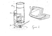
図2は、エアロゾール缶に内蔵された、ほぼ空のインジケータを表す。機能性ラベル32が、缶に付着されている。機能性ラベル32は、詰替品センサ34を含む。容器の中身があるレベルより下に下がると、詰替品センサ34が、基地モニタ38に信号を送る。基地モニタ38は、極近い将来に製品を交換する必要性を示す印刷メッセージを、ユーザに表示できる。詰替品センサは、ラベル内に内蔵された印刷可能な電池36によって、電力を供給される。
FIG. 2 represents the nearly empty indicator built into the aerosol can. A
図3は、単一の中央基地局と相互作用するための複数の容器についての性能を表す。トリガースプレー容器10は、RFIDタグ12を有する。この例では、接触子114は、容器内に鋳込まれている。スプレー缶30は、缶の製造中に内側に取り付けられた、ほぼ空のインジケータを有している。これらの容器は両方共、それぞれの容器のいずれかの中に残る製品のレベルがある所定の低いレベルに達したことを消費者に警告するために、基地のモニタと通信する。
FIG. 3 represents the performance for multiple containers for interacting with a single central base station. The
図4aは、芳香剤、殺虫剤、又は同様の薬剤を放散させるための、プラグイン装置を示す。薬剤は、プラグイン装置40によって収容されると共にRFIDタグ44を有する詰替え可能なカートリッジ42内に含まれている。RFIDタグからの接触子はタグから下方に延び、製品があるレベルより下に下がった時に、詰替品内に含まれる液体又はジェルの量が減少することによって、電気回路を切る。RFIDタグから送られた信号は、この状況を消費者に警告する。この例では、RFIDタグは、プラグイン装置の最上部のインジケータ・ライト45を点灯させる。プラグイン装置は、RFIDタグからの信号に対応する、音声メッセージを有していてもよい。他の実施の形態では、RFIDタグ信号が、ヒーター40内のタイマーをスタートさせてもよい。タイマーが設定されたタイムリミットに達した時に、詰替品がほぼ空であることを示す信号が起動される。
FIG. 4a shows a plug-in device for releasing fragrances, insecticides or similar agents. The medication is contained in a
図4bは、製品があるレベル以下に下がった時に電気回路を切る、容器内を下方に延びる接触子を有するRFIDタグ49を内蔵する、異なる種類のカートリッジ48を有する、同様のプラグイン装置46を示す。同様に、このような事象が生じた後に、RFIDタグは、インジケータ・ライト45を点灯させる。他の実施の形態では、ヒーター46内のタイマーがスタートするように、RFIDタグに報知させてもよい。タイマーが設定されたタイムリミットに達した時に、詰替品がほぼ空であることを示す信号が起動される。
FIG. 4b shows a similar plug-in
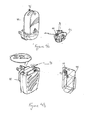
いくつかの薬剤及び他の製品は、コンセントに直接差し込まれているわけではなく、ベース・ユニット又は充電装置によって加熱される。図5は、磁場を生成するためのコイル50と、磁場を選択的に生成するためのコイルを制御するための回路基板等の制御装置52と、磁場を生成するために充電装置を手動で起動させるためのスイッチ53と、加熱可能な素子51と、読取機/書込機等の検出装置58と、を含む、充電装置を示す。蓄熱ユニット(heat storage unit)は、蓄熱ユニットについての情報を記憶するための無線周波識別装置59を有する。充電装置の検出装置は、RFIDタグによって、蓄熱ユニットの記憶情報を読み取る。蓄熱ユニットが充電装置の近くに置かれた時には、充電装置は、磁場を生成するために、自動的に起動される。蓄熱ユニット及び充電装置では、タグと読取機との間が0.1〜6インチの距離であることが好ましい。
Some medications and other products are not plugged directly into the outlet, but are heated by the base unit or charging device. FIG. 5 shows a
RFID読取機/書込機58は、制御装置52に接続されている。蓄熱ユニットは、アンテナを含むRFIDタグ59を有する。好ましくは、RFIDタグが蓄熱ユニットの外側に取り付けられているか、又は蓄熱ユニットと一体的に形成されている。適切な蓄熱ユニットが充電装置の近くに置かれると、タグは、読取機/書込機58に報知し、制御装置52がコイル50を起動させる。加熱可能な素子51は、生成された磁場の存在下で、熱を生成する。RFIDタグを有さないいずれの装置も、充電装置を起動させない。
The RFID reader /
充電器を起動させるために、容器が近くにあることを報知する以外に、より進んだ実施の形態において、RFIDタグ59は、特定の蓄熱ユニットについての好ましい加熱状況に関し、情報を読取機/書込機58に送信できる。この情報は、加熱時間及びピーク温度の両方を含んでいてもよい。さらに、RFIDタグは、充電器素子内に置かれた製品に関し、情報を読取機/書込機58に送信するために使用できる。読取機は、タグの独特の特徴(signature)を認識し、その特徴に対応する記憶された方法(regimen)をアクセスする。あるいは、タグは、加熱法を記憶し、この情報を読取機に送信してもよい。このようにして、単一の再充電器は、各々が異なる加熱法を有する、異なる芳香剤、殺虫材、清浄薬、臭気中和剤、液体洗浄剤、シェービング・クリーム、ローション、又は放散装置等の種々の製品に使用できる。
In addition to signaling that the container is nearby to activate the charger, in a more advanced embodiment, the
選択的に、RFIDタグは、書込可能な電子メモリを有していてもよい。電子メモリは、蓄熱ユニットの加熱履歴を含む、読取機/書込機58からの送信によって更新されてもよい記憶された情報を含む。充電装置が電源を入れ直すたびに充填装置がピーク温度を上げるように、ボトルの加熱履歴は、充電器に送信されてもよい。これにより、起こり得る感覚の鈍りに関する問題を克服するために、芳香剤の蒸発速度を徐々に増加させる。ボトルの履歴を送信することで、ボトルの中身の既知の持続時間に基づいて、ボトルを新しいものと取り替えるように、信号がユーザに送られてもよい。
Optionally, the RFID tag may have a writable electronic memory. The electronic memory includes stored information that may be updated by transmission from the reader /
制御回路に接続されたリアルタイム・クロックは、特定の蓄熱ユニットがどのくらい長く及びどのくらい最近加熱されたかを追跡続けることができる。それゆえ、本制御回路は、蓄熱ユニットが最近加熱された及び再び充電装置内にプラグインされた時等の場合における蓄熱ユニットの過熱を防止する。RFIDタグは、過熱を防止するために、蓄熱温度を検出する温度センサを有していてもよい。 A real time clock connected to the control circuit can keep track of how long and how recently a particular heat storage unit has been heated. Therefore, this control circuit prevents overheating of the heat storage unit, such as when the heat storage unit has recently been heated and plugged into the charging device again. The RFID tag may have a temperature sensor that detects a heat storage temperature in order to prevent overheating.
加熱揮発物質に加え、流動性の製品を含むボトルが充電装置内に置かれていてもよい。ボトル上のRFIDタグは、ボトルが近くに置かれたという情報を充電ユニットに送信し、選択的に、特定の流動性の製品の加熱法に関する情報を送信する。流動性の消費財を加熱するための充電器及び容器を、図5aに示す。図5のシステムと同様に、充電器は、制御装置52と、検出装置と、読取機/書込機58と、磁場生成器50と、を有する。充電器は、さらに、手動スイッチ53と、インジケータ・ライト54と、を有している。
In addition to the heated volatiles, a bottle containing a flowable product may be placed in the charging device. The RFID tag on the bottle sends information to the charging unit that the bottle has been placed nearby, and optionally information about how to heat a particular fluid product. A charger and container for heating fluid consumer goods is shown in FIG. 5a. Similar to the system of FIG. 5, the charger includes a
充電器と結合する(mating)容器は、バルブ・ステム134を有する加圧容器130を収容するハウジング140を有する。バルブ・ステムは、リザーバ120の入口116につながっている。リザーバは、アクチュエータ136によって加圧容器により放散される、1〜5ダースの流動性の製品を保持する大きさである。リザーバは、生成された磁場及び熱保持体180の存在下で熱を生成する加熱可能な素子151によって囲まれている。RFIDタグ59は、加熱素子の加熱を制御する。図5の実施の形態と同様に、充電器内に記憶された方法をアクセスするか、又はその方法を充電器に送信することによって、磁場発生器を始動させるか、又は特定の加熱法を始動させるために、タグは、適切な容器の存在を報知してもよい。図5及び5aに示される充電器の両方に当てはまるように、抵抗加熱等のいずれの種類の従来の加熱法が、磁場加熱の代わりに使用され得る。
The container mating with the charger has a housing 140 that houses a
図6は、コントローラによって起動された芳香剤ディスペンサ60を表す。コントローラは、ディスペンサに報知するための、プリント回路基板及びRFIDチップを有する、キーフォブ(key fob)62であってもよい。ユーザがディスペンサ内の芳香剤を放散できるように、信号は、ボタンによってユーザにより制御可能である。
FIG. 6 represents the
図7は、特定の芳香剤を放散するための制御に対応する、マルチ芳香剤ディスペンサ70を開示する。各芳香剤は、対応する特定のRFIDタグを有する。特定の信号に対応して放散されるべき芳香剤は、RFIDチップによってプログラムされている。芳香剤の放散に加え、コントローラは、RFIDチップに、LED等の種々の着色灯を点灯させる。ディスペンサは、単独で又は組み合わせて点灯する、種々の色のいくつかのLEDを有する。このようにして、嗅覚的刺激を伴うために、視覚的刺激が提供される。視覚的信号に加えて又はその代わりに、特定の音声信号が、特定の芳香剤の放散と共に生成可能である。 FIG. 7 discloses a multi fragrance dispenser 70 that corresponds to a control to dissipate a particular fragrance. Each fragrance has a corresponding specific RFID tag. The fragrance to be dissipated in response to a specific signal is programmed by the RFID chip. In addition to the release of the fragrance, the controller causes the RFID chip to light various colored lamps such as LEDs. The dispenser has several LEDs of different colors that can be lit alone or in combination. In this way, visual stimuli are provided to accompany olfactory stimuli. In addition to or instead of visual signals, specific audio signals can be generated with specific fragrance emissions.
図8は、古さ及び時間等の、RFIDタグから送信された情報を視覚的に表示するためのディスプレイ62を有する、読取機60を表す。さらに、読取機には、可聴可能に情報を送信するためのスピーカが設けられていてもよい。ディスプレイは、RFIDタグからの情報を受信するための、読取機内に収容された回路基板上のアンテナの位置を示す、目標領域64を有する。読取機が冷蔵庫のドア又は他の同様の装置から垂れ下がるように、フック66が読取機に設けられていてもよい。フックの代わりに、磁石等の他の取付装置、接着剤、又はベルクロ(VELCRO(R))が使用されていてもよい。読取機は、必要に応じて、RFIDタグに関するタイマーを初期化させタイマーをリセットするために使用される、開始ボタン68を有する。
FIG. 8 represents a
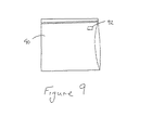
RFIDタグは、バッグ等の、剛性の又は可撓性の容器に取り付け可能である。図9は、RFIDタグ92を有するバッグ90を表す。RFIDタグ92は、読取機60上の開始ボタン68を押し下げることによって、初期化される。一旦、特定のRFIDタグによって初期化されると、タイミング・シーケンスが、初期化からの経過時間を記録し始める。単一の読取機により、再封止可能なバッグ又は他の種類の容器の上の複数のRFIDタグが監視可能である。タグは、製造業者によって取り付けられてもよく、消費者が取り付けるために別個に販売されてもよい。消費者によって取り付けられる場合には、RFIDタグは、使い捨てか又は限られた数の使用で再使用可能であってもよく、複数のバッグ又は容器に取り付けられていてもよい。この場合には、RFIDタグがある容器から他の容器に付け替えられる時には、初期化からの経過時間をさらに監視するために、読取機によって再初期化される。再使用可能な種類のタグを取り付け及び取り外しするために、種々のアタッチメント手段が使用可能である。図10に見られるように、バッグ等の容器に加え、RFIDタグ92が、バッグを再閉止するために使用されるクリップ93に取り付け可能である。最初にバッグを開けた後に、初期化されたRFIDタグでバッグを再閉止又は再密封するために、クリップ93が使用される。これにより、バッグが開けられてからの経過時間に関する情報を、消費者に与える。再使用可能なクリップは、最初にバッグに取り付けられるたびにリセットされるRFIDタグを有する。タグが使い捨てか又は使用回数が制限されている場合には、クリップは、ポケット又は窪み(recess) 内にタグを収める (nest)ための設備を有していてもよい。
The RFID tag can be attached to a rigid or flexible container, such as a bag. FIG. 9 represents a bag 90 having an
経過時間を監視するためのRFIDタグの使用は、多くの用途に使用できる。ルーチン保守を必要とするいずれの装置も、最後の保全周期からの経過時間を記録するためのRFIDタグを有していてもよい。ルーチンの定期的な保守を必要とする一般的な装置は、HVACシステム、園芸用品、及び自動車に関する種々のアイテムを含む。 The use of RFID tags to monitor elapsed time can be used for many applications. Any device that requires routine maintenance may have an RFID tag for recording the elapsed time since the last maintenance cycle. Typical equipment that requires routine periodic maintenance includes various items related to HVAC systems, garden supplies, and automobiles.
図11は、虫の存在を調べるRFIDタグ95を有する虫のトラップ94を表す。虫の活動によりRFIDタグを起動させ、信号をモニタ96に送る。トラップが虫の存在によって起動されたことを消費者に警告するために、モニタは、インジケータ・ライト97又はLCD表示(readout)98を有していてもよい。リセットボタン99は、トラップの有効性の判断において、モニタの有効性を増加させる。虫は、装置に報知するために、低出力の電気的トリガーを起動することができる。あるいは、虫の存在を発動させるために、フェロモンセンサが使用できる。
FIG. 11 shows an insect trap 94 with an RFID tag 95 that checks for the presence of the insect. The RFID tag is activated by the insect activity and a signal is sent to the
経過時間の他に、タグが取り付けられるアイテムに適した事前記録された情報が、RFIDタグ上に記録(place on)できる。たとえば、このような用途が衣類である。衣類には、取扱い表示を有するタグが設けられていてもよい。ドライクリーニングが必要か、汚れを除去するための最良の方法、及び洗濯目的のために同種の衣類に洗濯物の仕分けができるようにするための洗濯サイクルの種類が、RFIDタグの上に記録できる。教材として、タグには、衣類を子供が合わせられるようにさせる情報が提供されていてもよい。タグが製造業者によって取り付けられる場合には、タグは、くじ(sweepstake)又は他の宣伝活動に関する情報を記憶するために使用できる。また、タグは、家庭内の食料の在庫を追跡するための簡単な手段として使用出来る。 In addition to elapsed time, pre-recorded information suitable for the item to which the tag is attached can be placed on the RFID tag. For example, such a use is clothing. The clothing may be provided with a tag having a handling indication. The best way to remove dirt, whether dry cleaning is needed, and the type of wash cycle to allow laundry to be sorted into the same type of garment for laundry purposes can be recorded on the RFID tag . As a teaching material, the tag may be provided with information that allows children to wear clothes. If the tag is attached by the manufacturer, the tag can be used to store information about a sweepstake or other promotional activity. Tags can also be used as a simple means to keep track of food stock in the home.
RFIDタグに記憶させてもよい他の種類の情報は、調理説明書である。食料品の梱包は、調理説明書を有するRFIDタグを含んでいてもよい。パッケージを読取機の近くに置くと、RFIDタグは、調理の説明を提供する音声メッセージ又はスクリーン上の画像表示を開始出来る。 Another type of information that may be stored in the RFID tag is a cooking instruction. The food packaging may include an RFID tag having cooking instructions. When the package is placed close to the reader, the RFID tag can initiate a voice message or an on-screen display providing cooking instructions.
読取機は、RFIDタグが近くにあることを感知するから、タグは、鍵、ペットの首輪、又は紛失しやすい他のいかなるアイテムに内蔵されてもよい。携帯型読取機を使用すると、読取機がRFIDタグに近づくと必ず、ユーザは、音声又は視覚信号を受信できる。目下のところ、2メートルの近さが想定されている。しかしながら、所要電力によって、より大きな読取距離が実現可能である。それ自体の電源を有する能動的なタグ(active tag)を使用すると、より大きな距離が可能になる。しかしながら、当業者ならば、特定の用途に適した近接要求事項を調節できる。 Since the reader senses that the RFID tag is nearby, the tag may be embedded in a key, pet collar, or any other item that is easily lost. Using a portable reader, the user can receive audio or visual signals whenever the reader approaches the RFID tag. Currently, it is assumed to be close to 2 meters. However, a larger reading distance can be realized depending on the required power. Using an active tag with its own power supply allows for greater distances. However, one skilled in the art can adjust the proximity requirements appropriate for a particular application.
タグが餌に加えられげっ歯動物類(rodent)又は他の動物に摂取される程RFIDタグを小さくしてもよい。一旦摂取されると、タグの接近を示すために、読取機を使用することによって、タグは追跡されてもよい。 The RFID tag may be so small that the tag is added to the bait and consumed by rodents or other animals. Once ingested, the tag may be tracked by using a reader to indicate the approach of the tag.
いくつかの好適な実施の形態を参照して、特定の構成要素、材料、構造、配置等を示し説明したが、本発明はこれらの特定の実施の形態に限定されない。当業者であるならば、添付の特許請求の範囲によってのみ限定されるように意図されている、本発明の精神及び範囲内で種々の修正及び変形が可能であることを認識するであろう。 Although specific components, materials, structures, arrangements, etc. have been shown and described with reference to certain preferred embodiments, the invention is not limited to these specific embodiments. Those skilled in the art will recognize that various modifications and variations are possible within the spirit and scope of the invention, which is intended to be limited only by the scope of the appended claims.
Claims (21)
容器の一部に取り付けられたセンサを有する容器と、
前記センサから下方に延びる接触子と、
前記容器内の製品のレベルが前記接触子より下になった時に切れる電気回路と、
製品のレベルが低いことをユーザーに警告するために、前記電気回路が切れた時に前記センサからの信号を生成するための装置と、
前記ユーザーに警告するために、前記信号を通信するための、前記容器から分離した遠隔受信機と、
を備える、システム。 A system for informing the level of a product in a container,
A container having a sensor attached to a portion of the container;
A contact extending downward from the sensor;
An electrical circuit that cuts when the level of the product in the container falls below the contact;
A device for generating a signal from the sensor when the electrical circuit is disconnected to warn a user that the level of the product is low;
A remote receiver separated from the container for communicating the signal to alert the user;
A system comprising:
前記ベース内に嵌まる、RFIDタグを有する容器と、
を含むユニットにおいて、
前記容器が前記ベースの近くに置かれた時に、前記RFIDタグが、前記容器の存在を前記ベースに報知する、
ユニット。 Base and
A container having an RFID tag that fits within the base;
In units containing
When the container is placed near the base, the RFID tag informs the base of the presence of the container;
unit.
前記ベースが、マイクロプロセッサ・ベースの制御回路と動作可能に接続している無線周波識別読取機/書込機を有し、
前記読取機/書込機が、前記RFIDタグと関連した、電子メモリ内に記憶するための更新情報を送信する、
請求項5のユニット。 The RFID tag is attached to the container;
The base has a radio frequency identification reader / writer operatively connected to a microprocessor based control circuit;
The reader / writer sends update information associated with the RFID tag for storage in electronic memory;
The unit of claim 5.
揮発物質を有する少なくとも1つの容器と、
前記少なくとも1つの容器を保持するホルダーと、
前記揮発物質の放散を制御するRFIDタグと、を含む、
システム。 A volatile emission system,
At least one container having a volatile substance;
A holder for holding the at least one container;
An RFID tag for controlling the emission of the volatile material,
system.
請求項13のシステム。 The at least one container is a plurality of containers each having an RFID tag, and further includes a control device that controls which of the plurality of containers is diffused.
The system of claim 13.
前記アイテムに関連したRFIDタグと、
前記RFIDタグが前記読取機の近くにある時に、タイマーを初期化すると共に、開始からの経過時間を表示する、タイマーを有する読取機と、を含む、
システム。 A system for monitoring the age of an item,
An RFID tag associated with the item;
A reader with a timer that initializes a timer and displays an elapsed time from the start when the RFID tag is near the reader;
system.
Applications Claiming Priority (2)
| Application Number | Priority Date | Filing Date | Title |
|---|---|---|---|
| US42793402P | 2002-11-21 | 2002-11-21 | |
| PCT/US2003/037662 WO2004049237A2 (en) | 2002-11-21 | 2003-11-21 | Products having rfid tags for wireless interrogation |
Publications (1)
| Publication Number | Publication Date |
|---|---|
| JP2006507196A true JP2006507196A (en) | 2006-03-02 |
Family
ID=32393331
Family Applications (1)
| Application Number | Title | Priority Date | Filing Date |
|---|---|---|---|
| JP2004555724A Pending JP2006507196A (en) | 2002-11-21 | 2003-11-21 | Products with RFID tags for providing information to product consumers |
Country Status (7)
| Country | Link |
|---|---|
| EP (1) | EP1579181B1 (en) |
| JP (1) | JP2006507196A (en) |
| AT (1) | ATE352026T1 (en) |
| AU (1) | AU2003293041A1 (en) |
| CA (1) | CA2506886C (en) |
| DE (1) | DE60311312T2 (en) |
| WO (1) | WO2004049237A2 (en) |
Cited By (4)
| Publication number | Priority date | Publication date | Assignee | Title |
|---|---|---|---|---|
| JP2011127940A (en) * | 2009-12-16 | 2011-06-30 | St Corp | Method of detecting remaining amount and remaining amount detector |
| JP2017529650A (en) * | 2014-07-25 | 2017-10-05 | アルプス・サウス・ユーロプ・スポレチノスト・ス・ルチェニーム・オメゼニームAlps South Europe S.R.O. | Induction heaters for shaving and cosmetic products |
| JP2019524566A (en) * | 2016-08-11 | 2019-09-05 | 京東方科技集團股▲ふん▼有限公司Boe Technology Group Co.,Ltd. | Smart clip, packaging bag, and article storage management method |
| JP2021506360A (en) * | 2017-12-21 | 2021-02-22 | エス.シー. ジョンソン アンド サン、インコーポレイテッド | Piezoelectric active discharge device with improved airflow output |
Families Citing this family (23)
| Publication number | Priority date | Publication date | Assignee | Title |
|---|---|---|---|---|
| US7107836B2 (en) | 2003-12-19 | 2006-09-19 | Neopost Industrie Sa | Radio frequency tagging for indicia printing and product information |
| KR100793448B1 (en) | 2004-10-25 | 2008-01-14 | 교세라 가부시키가이샤 | Container device and device for providing information |
| JP4508824B2 (en) * | 2004-10-26 | 2010-07-21 | 京セラ株式会社 | apparatus |
| EP1912543A1 (en) * | 2005-08-13 | 2008-04-23 | Aquis Wasser-Luft-Systeme GmbH, Lindau | Sensor device provided with an oscillation circuit locating system and an encoded information transmission |
| US7164849B1 (en) * | 2005-09-13 | 2007-01-16 | The Dial Corporation | Vapor-emitting device with an active end of use indicator |
| WO2007091283A1 (en) * | 2006-02-09 | 2007-08-16 | Alenia Aeronautica S.P.A. | A method for tracking the manufacturing of a complex product by means of rfid technology |
| DE102006023192A1 (en) * | 2006-05-17 | 2007-11-22 | Vodafone Holding Gmbh | Packing device has data medium unit for calling up and/or playing back instructive information, with at least one electric data medium module in which at least two pieces of instructive information are stored |
| WO2007136795A1 (en) * | 2006-05-19 | 2007-11-29 | Porex Corporation | Vapor dispenser with indicator |
| DE102007007745B3 (en) * | 2007-02-16 | 2008-07-17 | Jerichow, Ulrich, Dr. | Device e.g. for delivering fragrances, has housing with electronic data-processing unit and in housing is discharge unit for supply of gas or aerosol fragrances |
| EP2237701A1 (en) * | 2008-01-28 | 2010-10-13 | Paolo Stefanelli | Container for fluid products, in particular perfumes, deodorants, creams and similar |
| EP2346554B1 (en) * | 2008-09-26 | 2015-09-16 | Oriel Therapeutics, Inc. | Inhaler mechanisms with radially biased piercers and related methods |
| US9402544B2 (en) | 2009-02-03 | 2016-08-02 | Abbott Diabetes Care Inc. | Analyte sensor and apparatus for insertion of the sensor |
| US9051163B2 (en) | 2009-10-06 | 2015-06-09 | Ecolab Inc. | Automatic calibration of chemical product dispense systems |
| FR2952432B1 (en) | 2009-11-10 | 2012-06-01 | Air Liquide | METHOD AND DEVICE FOR MONITORING THE CONTENT OF A FLUID MOBILE TANK |
| CA3134869C (en) | 2010-03-24 | 2024-03-05 | Abbott Diabetes Care Inc. | Medical device inserters and processes of inserting and using medical devices |
| CN102759390B (en) * | 2012-07-17 | 2015-02-25 | 成都九洲电子信息系统股份有限公司 | Water level monitoring method by radio frequency communication method |
| CN102768055B (en) * | 2012-07-17 | 2014-07-09 | 成都九洲电子信息系统股份有限公司 | Water level monitoring system using radio frequency communication method |
| US9631913B2 (en) | 2013-08-29 | 2017-04-25 | Mitutoyo Corporation | Calibration control device for metrology tools |
| GB2538501A (en) * | 2015-05-18 | 2016-11-23 | Rosemount Measurement Ltd | Improvements in or relating to level switches |
| CN110366441B (en) | 2017-03-06 | 2022-06-28 | 康明斯滤清系统知识产权公司 | Genuine filter identification with filter monitoring system |
| US10970773B2 (en) | 2017-07-25 | 2021-04-06 | Dollar Shave Club, Inc. | Smart cap and/or handle |
| US10909611B2 (en) | 2017-07-25 | 2021-02-02 | Dollar Shave Club, Inc. | Smart cap product reordering |
| US10813384B2 (en) | 2017-12-29 | 2020-10-27 | Altria Client Services Llc | Electronic vaping device having formulation level indicator |
Family Cites Families (9)
| Publication number | Priority date | Publication date | Assignee | Title |
|---|---|---|---|---|
| US5547616A (en) * | 1995-05-08 | 1996-08-20 | S. C. Johnson & Son, Inc. | Device for dispensing a volatile active ingredient |
| US5675516A (en) * | 1995-09-27 | 1997-10-07 | Inex Vision Systems, Inc. | System and method for determining pushup of a molded glass container |
| CA2231231A1 (en) * | 1998-03-05 | 1998-04-05 | Kenneth E. Smelquist | Remote flow sensor |
| US6024142A (en) * | 1998-06-25 | 2000-02-15 | Micron Communications, Inc. | Communications system and method, fleet management system and method, and method of impeding theft of fuel |
| AU5732600A (en) * | 1999-06-11 | 2001-01-02 | Creative Golf Designs, Inc. | Inventory control system |
| US6483473B1 (en) * | 2000-07-18 | 2002-11-19 | Marconi Communications Inc. | Wireless communication device and method |
| US6600418B2 (en) * | 2000-12-12 | 2003-07-29 | 3M Innovative Properties Company | Object tracking and management system and method using radio-frequency identification tags |
| WO2002100728A2 (en) * | 2001-06-13 | 2002-12-19 | Advanced Technology Materials, Inc. | Liquid handling system with electronic information storage |
| US7224273B2 (en) * | 2002-05-23 | 2007-05-29 | Forster Ian J | Device and method for identifying a container |
-
2003
- 2003-11-21 EP EP03790032A patent/EP1579181B1/en not_active Expired - Lifetime
- 2003-11-21 CA CA002506886A patent/CA2506886C/en not_active Expired - Fee Related
- 2003-11-21 DE DE60311312T patent/DE60311312T2/en not_active Expired - Lifetime
- 2003-11-21 JP JP2004555724A patent/JP2006507196A/en active Pending
- 2003-11-21 AT AT03790032T patent/ATE352026T1/en not_active IP Right Cessation
- 2003-11-21 AU AU2003293041A patent/AU2003293041A1/en not_active Abandoned
- 2003-11-21 WO PCT/US2003/037662 patent/WO2004049237A2/en active IP Right Grant
Cited By (5)
| Publication number | Priority date | Publication date | Assignee | Title |
|---|---|---|---|---|
| JP2011127940A (en) * | 2009-12-16 | 2011-06-30 | St Corp | Method of detecting remaining amount and remaining amount detector |
| JP2017529650A (en) * | 2014-07-25 | 2017-10-05 | アルプス・サウス・ユーロプ・スポレチノスト・ス・ルチェニーム・オメゼニームAlps South Europe S.R.O. | Induction heaters for shaving and cosmetic products |
| JP2019524566A (en) * | 2016-08-11 | 2019-09-05 | 京東方科技集團股▲ふん▼有限公司Boe Technology Group Co.,Ltd. | Smart clip, packaging bag, and article storage management method |
| JP2021506360A (en) * | 2017-12-21 | 2021-02-22 | エス.シー. ジョンソン アンド サン、インコーポレイテッド | Piezoelectric active discharge device with improved airflow output |
| US11517642B2 (en) | 2017-12-21 | 2022-12-06 | S. C. Johnson & Son, Inc. | Piezoelectric active emitting device with improved air flow output |
Also Published As
| Publication number | Publication date |
|---|---|
| AU2003293041A1 (en) | 2004-06-18 |
| DE60311312D1 (en) | 2007-03-08 |
| AU2003293041A8 (en) | 2004-06-18 |
| DE60311312T2 (en) | 2007-04-26 |
| EP1579181A2 (en) | 2005-09-28 |
| CA2506886A1 (en) | 2004-06-10 |
| ATE352026T1 (en) | 2007-02-15 |
| WO2004049237A2 (en) | 2004-06-10 |
| CA2506886C (en) | 2008-09-23 |
| WO2004049237A3 (en) | 2005-07-28 |
| EP1579181B1 (en) | 2007-01-17 |
Similar Documents
| Publication | Publication Date | Title |
|---|---|---|
| US7009519B2 (en) | Product dispensing controlled by RFID tags | |
| JP2006507196A (en) | Products with RFID tags for providing information to product consumers | |
| US7680691B2 (en) | Inventory management system using RFID | |
| ES2654046T3 (en) | Low-cost RFID radio frequency identification dispensing systems | |
| CN101801810B (en) | Spraying device and method of using same | |
| ES2959407T3 (en) | Beverage dispensing valve controlled by wireless technology | |
| EP0757654B1 (en) | Dispenser for an aerosol can | |
| US7336183B2 (en) | Decommissioning an electronic data tag | |
| US10940226B2 (en) | Dispenser | |
| EP2800502B1 (en) | Keyed dispensing system | |
| US20090236440A1 (en) | Dispenser comprising electromagnetic locking with a magnet and reed switch | |
| JP2010526735A (en) | Actuator cap of spray device | |
| JP2015511909A5 (en) | ||
| WO2001081178A1 (en) | Container and process for monitoring and recordal of production information | |
| US11938251B2 (en) | Automated modular environment modification device | |
| US20060219732A1 (en) | Capsule dispensing apparatus with refrigeration | |
| US8807390B2 (en) | Indication sequence for energy efficient volatile material dispensers | |
| US20240144182A1 (en) | Apparatus, system, and method of providing auto-replenishment for a bulk consumables container | |
| WO2021198970A1 (en) | Optimized container for a consumer product |
Legal Events
| Date | Code | Title | Description |
|---|---|---|---|
| A621 | Written request for application examination |
Free format text: JAPANESE INTERMEDIATE CODE: A621 Effective date: 20061020 |
|
| A977 | Report on retrieval |
Free format text: JAPANESE INTERMEDIATE CODE: A971007 Effective date: 20090108 |
|
| A131 | Notification of reasons for refusal |
Free format text: JAPANESE INTERMEDIATE CODE: A131 Effective date: 20090113 |
|
| A02 | Decision of refusal |
Free format text: JAPANESE INTERMEDIATE CODE: A02 Effective date: 20090908 |