JP2006500513A - Method and apparatus for operating multiple fuel engines - Google Patents
Method and apparatus for operating multiple fuel engines Download PDFInfo
- Publication number
- JP2006500513A JP2006500513A JP2004540174A JP2004540174A JP2006500513A JP 2006500513 A JP2006500513 A JP 2006500513A JP 2004540174 A JP2004540174 A JP 2004540174A JP 2004540174 A JP2004540174 A JP 2004540174A JP 2006500513 A JP2006500513 A JP 2006500513A
- Authority
- JP
- Japan
- Prior art keywords
- fuel
- engine
- operating characteristics
- electronic control
- pressure
- Prior art date
- Legal status (The legal status is an assumption and is not a legal conclusion. Google has not performed a legal analysis and makes no representation as to the accuracy of the status listed.)
- Pending
Links
- 239000000446 fuel Substances 0.000 title claims abstract description 214
- 238000000034 method Methods 0.000 title claims abstract description 48
- VNWKTOKETHGBQD-UHFFFAOYSA-N methane Chemical compound C VNWKTOKETHGBQD-UHFFFAOYSA-N 0.000 claims abstract description 74
- 239000003345 natural gas Substances 0.000 claims abstract description 37
- 239000002737 fuel gas Substances 0.000 claims abstract description 27
- 239000002826 coolant Substances 0.000 claims abstract description 20
- 239000007789 gas Substances 0.000 claims description 42
- 239000003502 gasoline Substances 0.000 claims description 6
- 239000007788 liquid Substances 0.000 claims description 6
- 230000007613 environmental effect Effects 0.000 claims description 5
- 239000002828 fuel tank Substances 0.000 claims description 5
- 230000009969 flowable effect Effects 0.000 claims description 3
- 241000269627 Amphiuma means Species 0.000 claims 4
- ATUOYWHBWRKTHZ-UHFFFAOYSA-N Propane Chemical compound CCC ATUOYWHBWRKTHZ-UHFFFAOYSA-N 0.000 claims 4
- 239000001294 propane Substances 0.000 claims 2
- 230000009977 dual effect Effects 0.000 abstract description 21
- 239000002283 diesel fuel Substances 0.000 description 35
- 238000002485 combustion reaction Methods 0.000 description 11
- 238000010586 diagram Methods 0.000 description 11
- 230000006870 function Effects 0.000 description 11
- 239000003570 air Substances 0.000 description 8
- 238000006243 chemical reaction Methods 0.000 description 7
- 230000001276 controlling effect Effects 0.000 description 6
- 238000013507 mapping Methods 0.000 description 6
- 230000008569 process Effects 0.000 description 5
- 238000004891 communication Methods 0.000 description 4
- 238000002347 injection Methods 0.000 description 4
- 239000007924 injection Substances 0.000 description 4
- 239000003344 environmental pollutant Substances 0.000 description 3
- 230000004048 modification Effects 0.000 description 3
- 238000012986 modification Methods 0.000 description 3
- 231100000719 pollutant Toxicity 0.000 description 3
- 230000001360 synchronised effect Effects 0.000 description 3
- 238000004364 calculation method Methods 0.000 description 2
- 230000007423 decrease Effects 0.000 description 2
- 230000000694 effects Effects 0.000 description 2
- 239000003208 petroleum Substances 0.000 description 2
- 238000003915 air pollution Methods 0.000 description 1
- 239000012080 ambient air Substances 0.000 description 1
- 230000008901 benefit Effects 0.000 description 1
- 230000033228 biological regulation Effects 0.000 description 1
- 230000005540 biological transmission Effects 0.000 description 1
- 230000000903 blocking effect Effects 0.000 description 1
- 230000008859 change Effects 0.000 description 1
- 238000001816 cooling Methods 0.000 description 1
- 239000002803 fossil fuel Substances 0.000 description 1
- 238000005259 measurement Methods 0.000 description 1
- 230000001473 noxious effect Effects 0.000 description 1
- 230000001105 regulatory effect Effects 0.000 description 1
- 239000004071 soot Substances 0.000 description 1
- 238000013024 troubleshooting Methods 0.000 description 1
Images


Classifications
-
- F—MECHANICAL ENGINEERING; LIGHTING; HEATING; WEAPONS; BLASTING
- F02—COMBUSTION ENGINES; HOT-GAS OR COMBUSTION-PRODUCT ENGINE PLANTS
- F02D—CONTROLLING COMBUSTION ENGINES
- F02D41/00—Electrical control of supply of combustible mixture or its constituents
- F02D41/0025—Controlling engines characterised by use of non-liquid fuels, pluralities of fuels, or non-fuel substances added to the combustible mixtures
- F02D41/0027—Controlling engines characterised by use of non-liquid fuels, pluralities of fuels, or non-fuel substances added to the combustible mixtures the fuel being gaseous
-
- F—MECHANICAL ENGINEERING; LIGHTING; HEATING; WEAPONS; BLASTING
- F02—COMBUSTION ENGINES; HOT-GAS OR COMBUSTION-PRODUCT ENGINE PLANTS
- F02D—CONTROLLING COMBUSTION ENGINES
- F02D19/00—Controlling engines characterised by their use of non-liquid fuels, pluralities of fuels, or non-fuel substances added to the combustible mixtures
- F02D19/02—Controlling engines characterised by their use of non-liquid fuels, pluralities of fuels, or non-fuel substances added to the combustible mixtures peculiar to engines working with gaseous fuels
- F02D19/026—Measuring or estimating parameters related to the fuel supply system
- F02D19/027—Determining the fuel pressure, temperature or volume flow, the fuel tank fill level or a valve position
-
- F—MECHANICAL ENGINEERING; LIGHTING; HEATING; WEAPONS; BLASTING
- F02—COMBUSTION ENGINES; HOT-GAS OR COMBUSTION-PRODUCT ENGINE PLANTS
- F02D—CONTROLLING COMBUSTION ENGINES
- F02D19/00—Controlling engines characterised by their use of non-liquid fuels, pluralities of fuels, or non-fuel substances added to the combustible mixtures
- F02D19/06—Controlling engines characterised by their use of non-liquid fuels, pluralities of fuels, or non-fuel substances added to the combustible mixtures peculiar to engines working with pluralities of fuels, e.g. alternatively with light and heavy fuel oil, other than engines indifferent to the fuel consumed
- F02D19/0602—Control of components of the fuel supply system
- F02D19/0607—Control of components of the fuel supply system to adjust the fuel mass or volume flow
- F02D19/061—Control of components of the fuel supply system to adjust the fuel mass or volume flow by controlling fuel injectors
-
- F—MECHANICAL ENGINEERING; LIGHTING; HEATING; WEAPONS; BLASTING
- F02—COMBUSTION ENGINES; HOT-GAS OR COMBUSTION-PRODUCT ENGINE PLANTS
- F02D—CONTROLLING COMBUSTION ENGINES
- F02D19/00—Controlling engines characterised by their use of non-liquid fuels, pluralities of fuels, or non-fuel substances added to the combustible mixtures
- F02D19/06—Controlling engines characterised by their use of non-liquid fuels, pluralities of fuels, or non-fuel substances added to the combustible mixtures peculiar to engines working with pluralities of fuels, e.g. alternatively with light and heavy fuel oil, other than engines indifferent to the fuel consumed
- F02D19/0623—Failure diagnosis or prevention; Safety measures; Testing
-
- F—MECHANICAL ENGINEERING; LIGHTING; HEATING; WEAPONS; BLASTING
- F02—COMBUSTION ENGINES; HOT-GAS OR COMBUSTION-PRODUCT ENGINE PLANTS
- F02D—CONTROLLING COMBUSTION ENGINES
- F02D19/00—Controlling engines characterised by their use of non-liquid fuels, pluralities of fuels, or non-fuel substances added to the combustible mixtures
- F02D19/06—Controlling engines characterised by their use of non-liquid fuels, pluralities of fuels, or non-fuel substances added to the combustible mixtures peculiar to engines working with pluralities of fuels, e.g. alternatively with light and heavy fuel oil, other than engines indifferent to the fuel consumed
- F02D19/0626—Measuring or estimating parameters related to the fuel supply system
- F02D19/0628—Determining the fuel pressure, temperature or flow, the fuel tank fill level or a valve position
- F02D19/0631—Determining the fuel pressure, temperature or flow, the fuel tank fill level or a valve position by estimation, i.e. without using direct measurements of a corresponding sensor
-
- F—MECHANICAL ENGINEERING; LIGHTING; HEATING; WEAPONS; BLASTING
- F02—COMBUSTION ENGINES; HOT-GAS OR COMBUSTION-PRODUCT ENGINE PLANTS
- F02D—CONTROLLING COMBUSTION ENGINES
- F02D19/00—Controlling engines characterised by their use of non-liquid fuels, pluralities of fuels, or non-fuel substances added to the combustible mixtures
- F02D19/06—Controlling engines characterised by their use of non-liquid fuels, pluralities of fuels, or non-fuel substances added to the combustible mixtures peculiar to engines working with pluralities of fuels, e.g. alternatively with light and heavy fuel oil, other than engines indifferent to the fuel consumed
- F02D19/0639—Controlling engines characterised by their use of non-liquid fuels, pluralities of fuels, or non-fuel substances added to the combustible mixtures peculiar to engines working with pluralities of fuels, e.g. alternatively with light and heavy fuel oil, other than engines indifferent to the fuel consumed characterised by the type of fuels
- F02D19/0642—Controlling engines characterised by their use of non-liquid fuels, pluralities of fuels, or non-fuel substances added to the combustible mixtures peculiar to engines working with pluralities of fuels, e.g. alternatively with light and heavy fuel oil, other than engines indifferent to the fuel consumed characterised by the type of fuels at least one fuel being gaseous, the other fuels being gaseous or liquid at standard conditions
- F02D19/0647—Controlling engines characterised by their use of non-liquid fuels, pluralities of fuels, or non-fuel substances added to the combustible mixtures peculiar to engines working with pluralities of fuels, e.g. alternatively with light and heavy fuel oil, other than engines indifferent to the fuel consumed characterised by the type of fuels at least one fuel being gaseous, the other fuels being gaseous or liquid at standard conditions the gaseous fuel being liquefied petroleum gas [LPG], liquefied natural gas [LNG], compressed natural gas [CNG] or dimethyl ether [DME]
-
- F—MECHANICAL ENGINEERING; LIGHTING; HEATING; WEAPONS; BLASTING
- F02—COMBUSTION ENGINES; HOT-GAS OR COMBUSTION-PRODUCT ENGINE PLANTS
- F02D—CONTROLLING COMBUSTION ENGINES
- F02D19/00—Controlling engines characterised by their use of non-liquid fuels, pluralities of fuels, or non-fuel substances added to the combustible mixtures
- F02D19/06—Controlling engines characterised by their use of non-liquid fuels, pluralities of fuels, or non-fuel substances added to the combustible mixtures peculiar to engines working with pluralities of fuels, e.g. alternatively with light and heavy fuel oil, other than engines indifferent to the fuel consumed
- F02D19/066—Retrofit of secondary fuel supply systems; Conversion of engines to operate on multiple fuels
-
- F—MECHANICAL ENGINEERING; LIGHTING; HEATING; WEAPONS; BLASTING
- F02—COMBUSTION ENGINES; HOT-GAS OR COMBUSTION-PRODUCT ENGINE PLANTS
- F02D—CONTROLLING COMBUSTION ENGINES
- F02D19/00—Controlling engines characterised by their use of non-liquid fuels, pluralities of fuels, or non-fuel substances added to the combustible mixtures
- F02D19/06—Controlling engines characterised by their use of non-liquid fuels, pluralities of fuels, or non-fuel substances added to the combustible mixtures peculiar to engines working with pluralities of fuels, e.g. alternatively with light and heavy fuel oil, other than engines indifferent to the fuel consumed
- F02D19/0663—Details on the fuel supply system, e.g. tanks, valves, pipes, pumps, rails, injectors or mixers
-
- F—MECHANICAL ENGINEERING; LIGHTING; HEATING; WEAPONS; BLASTING
- F02—COMBUSTION ENGINES; HOT-GAS OR COMBUSTION-PRODUCT ENGINE PLANTS
- F02D—CONTROLLING COMBUSTION ENGINES
- F02D19/00—Controlling engines characterised by their use of non-liquid fuels, pluralities of fuels, or non-fuel substances added to the combustible mixtures
- F02D19/06—Controlling engines characterised by their use of non-liquid fuels, pluralities of fuels, or non-fuel substances added to the combustible mixtures peculiar to engines working with pluralities of fuels, e.g. alternatively with light and heavy fuel oil, other than engines indifferent to the fuel consumed
- F02D19/08—Controlling engines characterised by their use of non-liquid fuels, pluralities of fuels, or non-fuel substances added to the combustible mixtures peculiar to engines working with pluralities of fuels, e.g. alternatively with light and heavy fuel oil, other than engines indifferent to the fuel consumed simultaneously using pluralities of fuels
- F02D19/10—Controlling engines characterised by their use of non-liquid fuels, pluralities of fuels, or non-fuel substances added to the combustible mixtures peculiar to engines working with pluralities of fuels, e.g. alternatively with light and heavy fuel oil, other than engines indifferent to the fuel consumed simultaneously using pluralities of fuels peculiar to compression-ignition engines in which the main fuel is gaseous
- F02D19/105—Controlling engines characterised by their use of non-liquid fuels, pluralities of fuels, or non-fuel substances added to the combustible mixtures peculiar to engines working with pluralities of fuels, e.g. alternatively with light and heavy fuel oil, other than engines indifferent to the fuel consumed simultaneously using pluralities of fuels peculiar to compression-ignition engines in which the main fuel is gaseous operating in a special mode, e.g. in a liquid fuel only mode for starting
-
- F—MECHANICAL ENGINEERING; LIGHTING; HEATING; WEAPONS; BLASTING
- F02—COMBUSTION ENGINES; HOT-GAS OR COMBUSTION-PRODUCT ENGINE PLANTS
- F02D—CONTROLLING COMBUSTION ENGINES
- F02D2200/00—Input parameters for engine control
- F02D2200/02—Input parameters for engine control the parameters being related to the engine
- F02D2200/04—Engine intake system parameters
- F02D2200/0406—Intake manifold pressure
-
- F—MECHANICAL ENGINEERING; LIGHTING; HEATING; WEAPONS; BLASTING
- F02—COMBUSTION ENGINES; HOT-GAS OR COMBUSTION-PRODUCT ENGINE PLANTS
- F02D—CONTROLLING COMBUSTION ENGINES
- F02D2200/00—Input parameters for engine control
- F02D2200/02—Input parameters for engine control the parameters being related to the engine
- F02D2200/06—Fuel or fuel supply system parameters
- F02D2200/0602—Fuel pressure
-
- F—MECHANICAL ENGINEERING; LIGHTING; HEATING; WEAPONS; BLASTING
- F02—COMBUSTION ENGINES; HOT-GAS OR COMBUSTION-PRODUCT ENGINE PLANTS
- F02D—CONTROLLING COMBUSTION ENGINES
- F02D2200/00—Input parameters for engine control
- F02D2200/02—Input parameters for engine control the parameters being related to the engine
- F02D2200/06—Fuel or fuel supply system parameters
- F02D2200/0606—Fuel temperature
-
- F—MECHANICAL ENGINEERING; LIGHTING; HEATING; WEAPONS; BLASTING
- F02—COMBUSTION ENGINES; HOT-GAS OR COMBUSTION-PRODUCT ENGINE PLANTS
- F02D—CONTROLLING COMBUSTION ENGINES
- F02D41/00—Electrical control of supply of combustible mixture or its constituents
- F02D41/0025—Controlling engines characterised by use of non-liquid fuels, pluralities of fuels, or non-fuel substances added to the combustible mixtures
-
- Y—GENERAL TAGGING OF NEW TECHNOLOGICAL DEVELOPMENTS; GENERAL TAGGING OF CROSS-SECTIONAL TECHNOLOGIES SPANNING OVER SEVERAL SECTIONS OF THE IPC; TECHNICAL SUBJECTS COVERED BY FORMER USPC CROSS-REFERENCE ART COLLECTIONS [XRACs] AND DIGESTS
- Y02—TECHNOLOGIES OR APPLICATIONS FOR MITIGATION OR ADAPTATION AGAINST CLIMATE CHANGE
- Y02T—CLIMATE CHANGE MITIGATION TECHNOLOGIES RELATED TO TRANSPORTATION
- Y02T10/00—Road transport of goods or passengers
- Y02T10/10—Internal combustion engine [ICE] based vehicles
- Y02T10/30—Use of alternative fuels, e.g. biofuels
Landscapes
- Engineering & Computer Science (AREA)
- Chemical & Material Sciences (AREA)
- Combustion & Propulsion (AREA)
- Mechanical Engineering (AREA)
- General Engineering & Computer Science (AREA)
- Oil, Petroleum & Natural Gas (AREA)
- Health & Medical Sciences (AREA)
- Biomedical Technology (AREA)
- Output Control And Ontrol Of Special Type Engine (AREA)
- Electrical Control Of Air Or Fuel Supplied To Internal-Combustion Engine (AREA)
Abstract
2又はそれ以上の燃料の組合せで動く複数燃料機関を作動させる方法及び装置が開示される。電子制御装置(ECU)は、複数燃料機関の作動を制御するために、エンジンシステムの既存部品へ連結される。エンジンシステムは、機械式に支配又は電子的に制御される。ECUは、エンジンシステムの作動特性を入力し、作動特性に基づいて、複数燃料の制御を支配するための特性を決定し、支配するための特性に基づいて、複数燃料機関への第一燃料及び第二燃料の供給量を制御する。望ましい実施例において、二重燃料エンジンは、ディーゼルを第一燃料、天然ガスを第二燃料として使いながら作動する。
作動特性として、エンジン速度、スロットル位置、エンジン排気温度、第二燃料のガス圧力、第二燃料の温度、吸気マニホルドのブースト圧力又はエンジン冷却剤温度を挙げることができる。A method and apparatus for operating a multiple fuel engine running on a combination of two or more fuels is disclosed. An electronic control unit (ECU) is coupled to the existing parts of the engine system to control the operation of the multiple fuel engine. The engine system is mechanically controlled or electronically controlled. The ECU inputs an operating characteristic of the engine system, determines a characteristic for controlling the control of the plurality of fuels based on the operating characteristic, and determines the first fuel to the multi-fuel engine based on the characteristic for controlling The supply amount of the second fuel is controlled. In the preferred embodiment, the dual fuel engine operates using diesel as the first fuel and natural gas as the second fuel.
The operating characteristics may include engine speed, throttle position, engine exhaust temperature, second fuel gas pressure, second fuel temperature, intake manifold boost pressure or engine coolant temperature.
Description
この出願は2002年9月24日提出の米国仮特許出願第60/413,269号の利益を要求する。 This application claims the benefit of US Provisional Patent Application No. 60 / 413,269, filed September 24, 2002.
本発明は電子制御装置(ECU)を使った複数燃料機関を作動するための方法および装置に関するものである。この複数燃料システムは機械式および電子制御式のエンジンの双方に応用できるであろう。一実施例として、内燃機関は、二つの燃料を組み合わせて作動する燃料機関システムに改変できる。具体的にはディーゼルを第一燃料に利用し天然ガスを第二燃料に利用するものである。 The present invention relates to a method and apparatus for operating a multiple fuel engine using an electronic control unit (ECU). This multiple fuel system could be applied to both mechanical and electronically controlled engines. As an example, the internal combustion engine can be modified to a fuel engine system that operates in combination with two fuels. Specifically, diesel is used as the first fuel and natural gas is used as the second fuel.
ガソリンを燃料とする内燃機関とディーゼルオイルを燃料とする内燃機関の運転に特有な大気汚染問題は、周知のことである。このため様々な排ガス制御装置が現在使われており、そして内燃機関による大気への汚染物質放出量を減らすことが連邦規則によって要求されるだろう。しかしながら、これらの排ガス制御装置は汚染物質の一部を取り除くだけであって、時間の経過とともに性能を低下することは免れない。またしばしばエンジンを最高の効率で運転することの妨げにもなっている。 Air pollution problems unique to the operation of internal combustion engines fueled by gasoline and diesel oil are well known. For this reason, various exhaust emission control devices are currently in use and federal regulations will require reducing the amount of pollutant emissions to the atmosphere by internal combustion engines. However, these exhaust gas control devices only remove some of the pollutants, and it is inevitable that the performance deteriorates over time. It also often prevents the engine from operating at maximum efficiency.
天然ガスも又内燃機関の燃料として使われる。天然ガスは燃焼汚染物質の発生を少なくし、複雑な排気制御装置なしでエンジン運転コストを抑え、その利用により世界の化石燃料消費率を減じることができる。 Natural gas is also used as a fuel for internal combustion engines. Natural gas reduces the generation of combustion pollutants, reduces engine operating costs without complex exhaust control devices, and can reduce the global fossil fuel consumption rate.
現在の輸送基幹施設(インフラ)は、広い地域に展開した十分な数の車用天然ガス小売店を備えていないので、天然ガスのような気体燃料だけを燃料とする車を作るのは走行距離の限界を考えれば実用的でない。車にガソリンやディーゼル燃料のような液体燃料を供給することと、補助的に天然ガスのような気体燃料を供給することの両方を具えることが、より実用的である。これを効率的に実行するためには、現存する燃料取り込みのシステムや形状への改良を最小限に抑えることが望ましい。 The current transportation infrastructure (infrastructure) does not have a sufficient number of natural gas retailers for cars deployed in a wide area, so it is the mileage to make a car that uses only gaseous fuel such as natural gas as fuel. It is not practical considering the limits of It is more practical to provide both a liquid fuel such as gasoline and diesel fuel to the car and a supplementary gaseous fuel such as natural gas. In order to do this efficiently, it is desirable to minimize improvements to existing fuel intake systems and shapes.
気体燃料と液体燃料を混合するために、様々なシステムが開発されてきた。例えば気体燃料を、ガス計量弁を通して、ディーゼルエンジンの空気吸引口多岐管へ供給される空気中へ浮遊させて運ぶシステムが設計された。その後この空気と燃料の組み合わせたものは、燃焼前にディーゼル燃料と混ぜ合わされる。この形式のシステムの一例が米国特許第4463734号に示されている。これらのシステムは、エンジンに入る空気の量で気体燃料の流入を制御するため、直接且つ一定値の気体燃料対ディーゼル燃料比が存在する。しかしながら様々なエンジンスピードによって、異なった負荷条件が起こることがあるために、このタイプのシステムは必ずしも最大限の効率をあげる混合率を提供するとは限らない。 Various systems have been developed for mixing gaseous and liquid fuels. For example, a system has been designed in which gaseous fuel is suspended and carried through a gas metering valve into the air supplied to the air intake manifold of the diesel engine. This combination of air and fuel is then mixed with diesel fuel before combustion. An example of this type of system is shown in U.S. Pat. No. 4,463,734. Since these systems control the inflow of gaseous fuel with the amount of air entering the engine, there is a direct and constant value of gaseous fuel to diesel fuel ratio. However, this type of system does not always provide the highest possible mixing rate, since different engine speeds can cause different load conditions.
引用をもって本願の一部とする米国特許第5370097号は、効率と出力を上げるために、内燃機関に入る気体燃料と液体燃料とを制御するシステムを開示している。 US Pat. No. 5,537,0097, which is incorporated herein by reference, discloses a system for controlling gaseous and liquid fuel entering an internal combustion engine to increase efficiency and power.
<発明の要旨>
本発明の実施例では、ひとつのエンジンシステムが、2またはそれ以上の数の燃料を組み合わせた燃焼によって作動する複数燃料機関へと改変される。又別の実施例として複数燃料機関は、様々なタイプの乗り物に関して独自の装備として利用される。複数燃料機関は、機械式エンジン又電子式エンジンのいずれにも適用できる。望ましい具体例では、複数燃料機関は、ディーゼルを第一燃料とし、天然ガスを第二燃料として作動する。
<Summary of the invention>
In an embodiment of the invention, an engine system is modified into a multiple fuel engine that operates by combustion combining two or more fuels. In another embodiment, the multiple fuel engine is utilized as a unique equipment for various types of vehicles. The multiple fuel engine can be applied to either a mechanical engine or an electronic engine. In a preferred embodiment, the multiple fuel engine operates with diesel as the first fuel and natural gas as the second fuel.
本発明の特徴は、複数燃料機関に電子式制御ユニット(ECU)を具えることである。ECUは、エンジンシステムの作動特性を入力すること、それから一つ以上の作動特性に基づきエンジンシステムへの第一及び第二燃料の放出の総量を制御することを可能にする。作動特性には、第二燃料のガス圧力、第二燃料のガス温度、吸気マニホルドのブースト圧力及び/又はエンジン冷却剤温度が含まれる。 A feature of the present invention is that a multiple fuel engine includes an electronic control unit (ECU). The ECU makes it possible to input operating characteristics of the engine system and then control the total amount of first and second fuel discharges into the engine system based on one or more operating characteristics. The operating characteristics include second fuel gas pressure, second fuel gas temperature, intake manifold boost pressure, and / or engine coolant temperature.
本発明のもう一つの特徴は、複数燃料機関への燃料供給量を制御する方法を提供することである。この方法は、ECUを供給し、エンジンシステムの作動特性を入力し、一つ以上の作動特性に基づきエンジンシステムへの第一及び第二燃料の供給量を制御することを含んでいる。 Another feature of the present invention is to provide a method for controlling the amount of fuel supplied to a multiple fuel engine. The method includes supplying an ECU, inputting operating characteristics of the engine system, and controlling supply amounts of first and second fuels to the engine system based on the one or more operating characteristics.
本発明はさらに、複数燃料機関に対するECUを較正する方法を提供する。この方法は、エンジンシステムの作動特性をECUに入力すること、作動特性に基づいて、複数燃料の燃焼を制御するための特性を決定すること、そしてその制御するための特性に基づいてエンジンへの第一及び第二燃料の供給量を制御することが含まれる。 The present invention further provides a method for calibrating an ECU for a multiple fuel engine. The method inputs engine system operating characteristics to an ECU, determines characteristics for controlling the combustion of multiple fuels based on the operating characteristics, and supplies the engine to the engine based on the controlling characteristics. Controlling the supply of the first and second fuels is included.
本発明は次に車のエンジンシステムを複数燃料機関に改変させる方法を提供する。この方法とはECUを装備することを意味する。一実施例として、この方法はさらに第二燃料用貯蔵タンクを搭載し、その第二燃料用貯蔵タンクとエンジンの間に、流通可能に第二燃料ラインを装備することを含む。 The present invention then provides a method for modifying a vehicle engine system to a multiple fuel engine. This method means installing an ECU. In one embodiment, the method further includes mounting a second fuel storage tank and equipping the second fuel storage tank with the second fuel line in a flowable manner.
この発明はさらに、エンジン、第一燃料用貯蔵タンク、第一燃料用貯蔵タンクとエンジンの間を流通可能に連結する第一燃料ライン、第二燃料用貯蔵タンク、第二燃料用貯蔵タンクとエンジンの間を流通可能に連結する第二燃料ライン、そしてECUを含む、複数燃料機関を提供する。 The present invention further includes an engine, a first fuel storage tank, a first fuel line that connects the first fuel storage tank and the engine in a flowable manner, a second fuel storage tank, a second fuel storage tank, and an engine. A multiple fuel engine is provided, including a second fuel line communicatively coupled between the ECU and an ECU.
この発明はさらに、複数燃料機関を作動させるためのコントロールソフトウェア又は、ランダムアクセスメモリーなど、その他のタイプのコンピュータ読み取りメディアを含む。 The present invention further includes other types of computer readable media, such as control software for operating multiple fuel engines or random access memory.
これらの、又は他の本発明の特徴は、次の説明から一層明らかとなるであろう。 These and other features of the present invention will become more apparent from the following description.
本発明の実施例は、エンジンシステムを二つ又はそれ以上の燃料の組み合わせで作動する複数燃料機関に改変する方法と装置を提供する。例えば二重燃料機関は「第一燃料」と「第二燃料」を使って作動することが可能になる。二重燃料モードでは、エンジンは第一と第二の燃料を組み合わせて動き、その他の場合には、エンジンは第一燃料だけを使って単式燃料モードで動く。好具体例として、二重燃料機関はディーゼルを第一燃料とし、天然ガスを第二燃料として使いながら作動する。好ましい実施例としては、第1燃料としてディーゼル、第2燃料として天然ガスを用いる二重燃料エンジンがある。ここで示されている好ましい具体例は、ディーゼルと天然ガスの使用に焦点を当てているが、適当な、どのような気体燃料または液体燃料でも、例えば石油系であろうと非石油系であろうと、それらも含めて、いずれか一方の燃料として利用できる。 Embodiments of the present invention provide a method and apparatus for modifying an engine system to a multiple fuel engine operating with a combination of two or more fuels. For example, a dual fuel engine can be operated using "first fuel" and "second fuel". In dual fuel mode, the engine operates in combination with the first and second fuels, otherwise the engine operates in single fuel mode using only the first fuel. As a good example, a dual fuel engine operates using diesel as the first fuel and natural gas as the second fuel. A preferred embodiment is a dual fuel engine using diesel as the first fuel and natural gas as the second fuel. The preferred embodiment shown here focuses on the use of diesel and natural gas, but any suitable gaseous or liquid fuel, for example petroleum-based or non-petroleum-based , Including them, can be used as either fuel.
ここで述べられている具体例は、既存のシステムを複数燃料機関に改変するために電子制御ユニット(ECU)を利用することに焦点を当てている。「エンジンシステム」は、ポンプ、燃料タンク、計測器、バルブ、その他複数燃料機関を造るために必要とされ、又ECUの一部としては含まれていない部品など、存在する全てのエンジン部品を含む。電子制御エンジン用に、エンジンシステムは、下請製造者(OEM)制御器も含んでいる。 The example described here focuses on using an electronic control unit (ECU) to modify an existing system to a multiple fuel engine. "Engine system" includes all existing engine components, such as pumps, fuel tanks, instruments, valves, and other parts that are required to build multiple fuel engines and are not included as part of the ECU . For electronically controlled engines, the engine system also includes a subcontract manufacturer (OEM) controller.
一般的には、改変処理は実質的には同じ動力とトルク性能を維持し、既存のエンジンを変更しない。その代わりECUが既存のエンジンシステムに連結されて、広い範囲の作動条件に対して、信頼性のある出力のために燃料供給を管理し、排気制御を行う。例えば、エンジンは、スイッチによって複数燃料モードの必要が示されるまでは100パーセントディーゼル(第一燃料)で動くようになっている。スイッチが入ると、ECUが作動して、燃焼を起こすのに必要な最小限の量のディーゼル燃料(つまり天然ガスのパイロット点火に必要な最低量)を使い、エンジンを動かすのに十分な天然ガス(第二燃料)を供給する。エンジンに供給されるディーゼルと天然ガスの量を調整する際、ECUは性能を最大限にしつつ、その一方で排気を最小限に抑えようとする。 In general, the modification process maintains substantially the same power and torque performance and does not change the existing engine. Instead, an ECU is connected to an existing engine system to manage fuel supply and perform exhaust control for reliable output over a wide range of operating conditions. For example, the engine is running on 100 percent diesel (first fuel) until a switch indicates the need for multiple fuel modes. When switched on, the ECU is activated and uses the minimum amount of diesel fuel necessary to cause combustion (i.e., the minimum amount required for pilot ignition of natural gas) and sufficient natural gas to run the engine. (Second fuel) is supplied. When adjusting the amount of diesel and natural gas supplied to the engine, the ECU attempts to maximize performance while minimizing emissions.
既存のエンジンシステムは機械式に支配され、または電子式に制御されている。機械式のエンジンでは、ECUはエンジンシステムの『作動特性』を記録する複数センサーを含む。その作動特性は、エンジンスピード(r.p.m.)、エンジン(又は排気)温度、スロットル位置、第二燃料のガス圧力、ディーゼルインジェクターの吸気マニホルドのブースト圧力及び/又はエンジン冷却剤温度が含まれる。電子式エンジンに関しては、ECUは、このような作動特性のための入力信号を受け取っている。しかしながら、少なくとも作動特性の入力のいくつかは、特定のセンサーのかわりに、既存のOEMコントローラーから直接入る。これらの作動特性に基づいて、ECUは、「マッピング」として知られているプロセスにおいて、複数燃料機関の「制御特性」を決定することにより、それ自身を較正(calibrate)してもよい。制御特性は、複数燃料システムの動き規定し、各々記録された作動特性に対応するエンジンパラメーターである。そこでエンジンスピードのような所定の作動特性について、ECUは、二重燃料作動を規定するエンジンスピードのための制御特性をマップする。ECUは、それから、それぞれの燃料の供給の調節をいつ、どれくらいの量でするかを決定する制御特性を用いる。目標とするべき最大限のロードとトルクの比は、例えば、80%の天然ガスと20%ディーゼルである。この目標の比率あたりで、有害ガスが顕著に減少され、目に見える煤煙は事実上除去される。 Existing engine systems are either mechanically controlled or electronically controlled. In a mechanical engine, the ECU includes multiple sensors that record the “operating characteristics” of the engine system. The operating characteristics include engine speed (r.p.m.), engine (or exhaust) temperature, throttle position, second fuel gas pressure, diesel injector intake manifold boost pressure and / or engine coolant temperature. For electronic engines, the ECU receives input signals for such operating characteristics. However, at least some of the operating characteristic inputs come directly from existing OEM controllers instead of specific sensors. Based on these operating characteristics, the ECU may calibrate itself by determining the “control characteristics” of the multiple fuel engines in a process known as “mapping”. The control characteristics are engine parameters that define the movement of the multiple fuel system and each correspond to a recorded operating characteristic. Thus, for a given operating characteristic, such as engine speed, the ECU maps the control characteristic for engine speed that defines dual fuel operation. The ECU then uses control characteristics that determine when and how much to adjust each fuel supply. The maximum load to torque ratio to be targeted is, for example, 80% natural gas and 20% diesel. Around this target ratio, noxious gases are significantly reduced and visible soot is virtually eliminated.
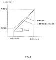
ECUは既存の機械調整器を取り除くことなくインストールできる。結果として、スピード調整特性は、スピードを操作する機械調整器に非常に、それよりも高度ではないが、近いものになっている。言い換えればECUは、複数燃料運転中、図1に示されているように機械調整器のr.p.m.を超えることはないが非常に近いr.p.m.で、エンジンスピードを制御することが望ましい。これは複数燃料運転中、機械調整器がキックイン(駄目になる)し、第一燃料、例えばディーゼルの供給を遮断すること、すなわちエンジンサージとして知られている状態に陥るのを避ける。 The ECU can be installed without removing the existing machine regulator. As a result, the speed adjustment characteristics are very close to, but not as advanced as, the mechanical regulator that operates the speed. In other words, it is desirable for the ECU to control the engine speed at a very close r.p.m., which does not exceed the r.p.m. of the mechanical regulator, as shown in FIG. This avoids the machine regulator kicking in during multiple fuel operation and shutting off the supply of the first fuel, eg diesel, that is, a condition known as engine surge.
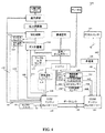
図2は機械式に調整されたエンジンから改変された二重燃料エンジンシステムの概略図である。図に示されているように、二重燃料システム10は、第一燃料(例えばディーゼル燃料)を単独で、又は第二燃料(例えば圧縮天然ガス)と組み合わせて、燃料噴射装置12を具えているエンジン11に供給する。燃料噴射装置12はエンジンのシリンダー中へ直接に燃料を注入する。図2に於いて、第一燃料は第二燃料が圧縮天然ガス(CNG)である間はディーゼルである。しかしながら、適切であればどのような燃料でも、第一燃料又は第二燃料として利用できる。
FIG. 2 is a schematic diagram of a dual fuel engine system modified from a mechanically tuned engine. As shown, the
システム10は、高圧ガス貯蔵タンク15を含んでおり、これは天然ガスを、エンジン11の吸気口へ流れる気流中へ引き込むために搭載されている空気/ガスミキサー17へ、コンジット16を通じてCNGを供給するものである。空気/ガスミキサー17は、ジョージア州リバーデイルのコンバションラブス社製SP4Dモデルのような、従来の任意のミキサーでよい。高圧遮断バルブ19、圧力調節器20、低圧遮断バルブ21及び燃料計量アクチュエーターが、天然ガスの流れを制御するために、タンク15とミキサー17の間のコンジット16へ直列に連結されている。圧力調節器20は、システム10と共に使われているエンジンのサイズや形式に応じた適切な圧力まで、天然ガスの圧力を低下させる。燃料計量アクチュエーター22は、イリノイ州ラブズパークのバーバーコールマン社製DYNK10322-800型のような、適切であれば任意のアクチュエーターでよい。濾過された外界空気が、コンジット24を経てミキサー17へ供給される。
The
システム10は又、燃料ポンプ28に連結されたディーゼル燃料貯蔵タンク27を含んでおり、該燃料ポンプは、コンジット29を通して、エンジン燃料インジェクター12へディーゼル燃料を供給している。燃料ポンプ28は一般的にエンジンによって運転されていて、その出力はエンジンのスピードと相関している。燃料ポンプ28は従来型の機械調整器(図示せず)、遮断レバー31及びスロットル32を具えている。遮断レバー31は、スロットル32が行なっているように、ポンプ28によって送り出されるディーゼル燃料の流れを制限するために使われる。二つのスロットルの効果的な使い方は、エンジンが作動していない時には、ディーゼル燃料がエンジンに入るのを防ぐ場合である。スロットル32は可動ケーブル34によってアクセルペダル33に連結されている。アクセルセンサー37は足動式アクセルペダル33のポジションを感知するために使われており、そしてそれによって、スロットル32を制御する。タンク27、ポンプ28、コンジット29、スロットル32、遮断レバー31、アクセルペダル33そしてケーブル34は、ディーゼルエンジン搭載の自動車には標準の装備であろう。
The
既存の部品がECU45の使用によって二重燃料機関へと改変される。エンジン冷却剤温度センサー38、エンジンスピードすなわちr.p.m.センサー39、そして排気温度センサー40は、エンジン11及びECU45に、各々信号回線41、42、43によって連結される。ガス圧力センサー46とガス温度センサー47は、ガス供給16とECU45に、各々信号回線48、49によって連結される。ブースト圧力センサー50は吸気マニホルドインジェクター12とECU45に信号回線51によって連結される。
Existing parts are converted to dual fuel engines by use of the
ECU45は、ディーゼル燃料制御アクチュエーター52へ信号出力ライン53とフィードバックライン54によって連結される。ディーゼル燃料制御アクチュエーター52は機械的に順次遮断レバー31へとケーブル55によって連結される。信号ライン57によってECU45へ繋がっている2位置燃料セレクター56が配備されている。ECU45は又、遮断バルブ19と21の両方へ制御ライン57によって、燃料計量アクチュエーター22へ制御ライン58とフィードバックライン59によって、そして最後にアクセルセンサー37とライン60によって連結されている。
The
最初にシステムを較正するために、セレクタースイッチ56は「オフ」の位置にあり、従ってエンジンはディーゼル燃料のみで作動する。それからエンジンは、エンジンが最高エンジン速度になるように、アクチュエーター52によって、スロットル32を全開にし、燃料ポンプ遮断レバー31を全開にする。次に、例えば通常の動力計のように負荷がエンジンに加えられ、エンジン速度を所定増分量、一般的には約200r.p.m.低下させる。次にエンジンのトルク、馬力、排気温度が動力計によって決定され、ECU45のメモリーの内部に蓄えられる。エンジン負荷によって作動停止するに至るまで、エンジンは設定増分量で段階的に減速する。エンジンスピードの各増分段階で、結果として生じる最大エンジントルク、馬力、排気温度がECU45メモリーに記録され蓄えられる。これらの作動特性に基づいて、ECU45は二重燃料運転の制御特性を決定する。この手法は、エンジンをマッピングすると呼ばれる。好ましい具体例では、ECU45はr.p.m.の範囲で256r.p.m.値まで記憶する。
To initially calibrate the system, the
次にセレクタースイッチ53がオンになり、エンジンはディーゼル燃料と天然ガスの両方で作動する。エンジンは遮断レバー31を完全に開けた状態で空転するようになる。それから、遮断レバーはゆっくりアクチュエーター52の活動により閉じられるが、その結果ディーゼル燃料の流動を制限し、同時にディーゼル燃料の減少を補うために、燃料計量アクチュエーター22の活動が天然ガスの流入を増加させる。このように、アクチュエーター22と52は、ディーゼル燃料の量が燃焼のための最小限以下になって、エンジンスピードが維持できなくなるまで作動する。このディーゼル燃料の最小限量は普通『パイロット燃料』と呼ばれる。アクチュエーター52とエンジンスピードのポジションは基準値としてECU45に蓄えられる。
The
遮断レバーはそれから全開位置に戻され、スロットル32はエンジンスピードを、予め設定された増分量で、予めマップされた次のエンジンスピードにまで増加させるポジションに動かされる。アクチュエーター22と52は再び作動して、上で述べたように、この特定のエンジンスピードのために、アクチュエーター52のパイロット燃料ポジションを決定して記憶する。この過程は、先に記憶されたエンジンスピードごとに、そのエンジンスピードの範囲でずっと繰り返され、そして対応する基準値は記録される。最小限では、パイロット燃料は全燃料の約5%になることが判明した。
The shut-off lever is then returned to the fully open position and the
各エンジンスピード毎のエンジントルクと馬力のマッピングで予めプログラムされたECU45を使って、ECU45はディーゼル燃料と天然ガスの流れを、エンジンを過剰駆動するマップされた状況を超えないような形で、規制する。言い換えれば二つの燃料の組み合わせは、ディーゼル燃料だけで従来作動しているエンジンによって産出される以上のエンジントルク或いは馬力を生んだりはしない。好具体例では、ECU45はガス温度、ガス圧力、吸気マニホルドブースト圧力を考慮し、変化する環境状況にしたがってディーゼル対ガス比率を調節する。エンジン排気と冷却温度もまた、エンジンが暖かいときにはガスが注入されることが望ましいという理由から、考慮される。エンジン11の点火装置が切られている状態で、天然ガス遮断バルブ19と21そしてディーゼルポンプ遮断レバー31は、天然ガスもディーゼル燃料もエンジンに入らないように閉じられる。
Using a
エンジン11をディーゼル燃料だけで作動させるためには、セレクター56がオフ位置にされなければならない。セレクターがこのポジションのとき、遮断バルブ19と21は、天然ガスがエンジンに入らないように閉じられたままである。エンジンの点火装置が発動すると、遮断レバー31が完全に開いて、その結果ディーゼルポンプ28がディーゼル燃料をコンジット29経由でエンジンのインジェクター(燃料噴射装置)12の中へ押し入れる。エンジンに供給されるディーゼル燃料の流動比率は、機械調整器とスロットル32のポジションによって決まる。ディーゼル燃料との組み合わせの中で使われる空気は、空気/ガスミキサー17を通してエンジンに入る。
In order to operate the engine 11 with only diesel fuel, the
燃料システム10を二重燃料方式にしてエンジン11を起動して作動させるために、セレクター56がオンに選択され、それによってECU45が発動する。エンジンを起動させる間は、天然ガスをエンジンに入れるとは、シリンダー中の圧力によってエンジンを「ロックアップ」させるので、望ましくない。それゆえにr.p.m.センサー39が、予め選ばれた最低速度以上でエンジンが運転していないことを示すと、ECU45は遮断バルブ19と21を閉じたままにするよう信号を送る。いったんエンジンが、予め選ばれた最低速度を超えて運転すると、ECU45がディーゼル燃料制御アクチュエーター52を作動させ、天然ガスを圧力調節器20と計量アクチュエータ22を通して入れるために、遮断バルブ19と21を開ける。
In order to start and operate the engine 11 by setting the
エンジンに供給される各燃料の量はECU45によって決定されるのだが、これは燃料計量アクチュエーター22を通る天然ガスの流動及びポンプ28からのディーゼル燃料の流動を規制することで、実行される。これはスロットル32と遮断レバー31のポジショニングの選択によって決定される。ECU45は、r.p.m.センサー39とアクセルセンサー37によって与えられる情報に従って流動を規制することができる。
The amount of each fuel supplied to the engine is determined by the
図3は、機械式エンジンを二重燃料機関システムへ改変するための一般的なECU70の概略図である。示されているように、天然ガスは吸気マニホルドに噴射するインジェクター71−76を6個まで使って制御されている。それに替わって、天然ガスを制御するには、プロポーショナルバルブを使ってもよい。ECU70は、要求されているエンジン制御パラメーターの迅速な計算のために、32ビットマイクロコントローラーのような適切な制御器を内蔵している。ECU70は又、ランダムアクセスメモリーのような適切なメモリーも内蔵している。プログラムはフラッシュメモリーに全部収められ、要求があればフィールドへの置き換えも、アップグレードも可能である。EEPROMメモリーが、較正(キャリブレーション)、データやマップや障害コードなどを収めるのに使われる。1つのサーボモーターアウトプット80は、ディーゼルパイロットポジショナーの制御に用いられている。アナログ入力は、スロットルポジションセンサー81、エンジンスピードセンサー82、ガス圧力センサー83、マニホルドブースト圧力センサー84、排気温度センサー85、冷却剤温度センサー86などのシステムセンサーの読み取りに使われている。デジタル入力もまた、r.p.m.、スピード、タイミング、バイナリーセンサーやその他、システム形態に応じたロジック信号などを読み取るために含まれてもよい。加えてECUは、システムエネイブルスイッチ87とパワーテイクオフ(PTO)エネイブルスイッチ88を含んでもよい。図3は、ガスバルブ89とシステムオンライト90に関するシステムを示している。
FIG. 3 is a schematic diagram of a
RS422の完全複式ポート(図には示されていない)が、ラップトップコンピュータで起動するプログラミングと分析ソフトウェアとの連絡に提供されてもよい。制御ソフトウェアは、特別な用途での必要にあわせて、般用ソフトウェアからプログラムしたりカスタマイズしたりできる。機械式エンジンのために使われる一般的ソフトウェアは、空転(アイドル)制御、トルクマッピング、エンジンr.p.m.マッピング、ディーゼルパイロットマッピング、ガス圧力補償、マニホルド圧力補償、そしてPTO制御を含む。このソフトウェアは、各センサーの分析の役割を果たす。センサーに障害が生じた場合はシステムが不能になり、フォールトコードが記録される。そのフォールトコードは、システムトラブルシューティングの間に復旧される。 A full duplex port of RS422 (not shown) may be provided for communication with the programming and analysis software running on the laptop computer. The control software can be programmed or customized from general software to meet the needs of special applications. Common software used for mechanical engines includes idle (idle) control, torque mapping, engine r.p.m. mapping, diesel pilot mapping, gas pressure compensation, manifold pressure compensation, and PTO control. This software serves to analyze each sensor. If a sensor fails, the system is disabled and a fault code is recorded. The fault code is recovered during system troubleshooting.
較正ソフトウェアは、プログラムと分析モニター(PDM)として知られている。このソフトウェアは、一般的ラップトップコンピュータのウィンドウズ(登録商標)のもとで使える。全部のセンサー、使われたガス、ディーゼルパイロットアクチュエーターポジションや様々なステータスフラッグがディスプレイされている。較正データは、スクリーンから又はファイルからECUに直接アップロードできるし、もし必要があれば、再びダウンロードしてファイルに入れておける。 The calibration software is known as a program and analysis monitor (PDM). This software can be used under the Windows of a general laptop computer. All sensors, gas used, diesel pilot actuator position and various status flags are displayed. The calibration data can be uploaded directly to the ECU from the screen or from a file, and can be downloaded again into the file if necessary.
機械式エンジンに比べて、電子式エンジンは所定の作動特性を測るために、既存のセンサーを含み、又はインターフェイスで連結もできるOEM制御器を通常は内蔵する。このようにして、本発明のECUはOEM制御器と調和して機能し、OEM制御器が感知し記録した作動特性を受け取るためにデータリンク信号経由でOEM制御器と連絡する。OEM制御器が感知せず記録しない作動特性については、ECUは、それ自身のセンサー、例えばガス圧力、ガス温度、ブースト圧力センサーを具えることもできる。機械式エンジンのように、電子式エンジンの作動特性は、エンジンスピード(r.p.m.)、エンジン(又は排気)温度、スロットルポジション、第2燃料のガス圧力、第2燃料のガス温度、インジェクター吸気マニホルドのブースト圧力、及び/又はエンジン冷却剤温度などを含むことができる。 Compared to a mechanical engine, an electronic engine typically includes an OEM controller that can include existing sensors or can be interfaced to measure predetermined operating characteristics. In this way, the ECU of the present invention functions in concert with the OEM controller and communicates with the OEM controller via the data link signal to receive operating characteristics sensed and recorded by the OEM controller. For operating characteristics that are not sensed and not recorded by the OEM controller, the ECU may also have its own sensors, such as gas pressure, gas temperature, boost pressure sensors. Like a mechanical engine, the operating characteristics of an electronic engine are: engine speed (rpm), engine (or exhaust) temperature, throttle position, second fuel gas pressure, second fuel gas temperature, injector intake manifold boost. Pressure, and / or engine coolant temperature, and the like.
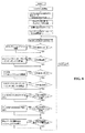
図4は電子制御エンジンから改変された二重燃料エンジンシステム100の概略図である。いくつかの部品は、図2で機械制御システム用に描かれた部品と一致する。異なっている部品は、下に描かれている。
FIG. 4 is a schematic diagram of a dual
図4で示されているように既存のOEM制御器101は、エンジンスピードセンサー102、冷却剤温度センサー103、アクセルセンサー104、マニホルド圧力センサー123、マニホルド温度センサー124、環境圧力センサー125、環境温度センサー126、車スピードセンサー130から、夫々信号回線105、106、107、140、141、142を通じて作動特性を受け取ることができる。
As shown in FIG. 4, the existing
既存の部品は、ECU110の使用によって、二重燃料機関へと改変される。ガス圧力センサー111、ガス温度センサー112、ブースト圧力センサー113、そしてエンジン排気温度センサー114と、それぞれ信号回線115、116、117、118を通して連結することができる。ECU110は又、ガス計測器119と信号回線120によって連結され、又信号回線121を通してエンジンへのガスの流れを規制することができる。加えて、ECU110はOEM制御器とデータリンク145によって連結することができる。実施例としては、SAEJ1939データリンクが使われていることが望ましい。ECU110はエンジンスピード、冷却剤温度、アクセルポジション、環境温度、環境圧力、マニホルド温度、マニホルド圧力、車の速度の測定値を、データリンク145から受け取ることができる。加えて、ECU110は、トルク制御、r.p.m.制御、パワーテイクオフ(PTO)制御、そして車の速度制御に関するOEM制御器101の作動についての情報を、障害分析情報やエンジン構成情報と共に受け取る。
Existing parts are converted into dual fuel engines by use of the
一旦ECU110が作動特性を受け取ると、つぎにシステムを較正し二重燃料運転のための制御特性を発生させる。ECU110は、OEM制御器101に信号を送ることによって、ディーゼル燃料の流れを調節するために、又ガス計測器119へ信号を送ることによって、天然ガスの流れを調節するために、制御特性を使う。
Once
図5は、電子式エンジンを二重燃料機関システムへ改変するための一般的なECU150の概略図である。示されているように、天然ガスは、吸気マニホルドに噴射する6個までのインジェクター151−156を使って制御されている。替わって、天然ガスを制御するのにプロポーショナルバルブを使うこともできる。吸引マニホルドへの天然ガス噴射ポートを使うこともできる。ECU150は、要求されているエンジン制御パラメーターの迅速な計算のために、32ビットマイクロコントローラーのような適切な制御器を内蔵している。ECU150は又適切なメモリーも内蔵している。プログラムはフラッシュメモリーに全部収められ、要求があればフィールドへの置き換えやアップグレードも可能である。EEPROMメモリーは、較正データやマップやフォールトコードなどを記憶するのに使われる。アナログ入力は、ガス圧力センサー160、マニホルドブースト圧力センサー161、ガス温度センサー162、排気温度センサー163などのシステムセンサーの読み取りに使われている。エンジンスピード、冷却剤温度、スロットルポジションは、OEM制御器165のデータリンク接続から読み取ることができる。ECU150はまたデータリンク165との連絡のためにCANポート166を搭載している。加えて、このECUは、システムエネイブルスイッチ167とPTOエネイブルスイッチ168を含む。図5はガスバルブ169とライト170に関するシステムも示している。
FIG. 5 is a schematic diagram of a
RS422完全二重ポート(図には示されていない)は、ラップトップコンピュータで作動するプログラミングと分析ソフトウェアとの伝達に供給される。電子式エンジンでは、制御ソフトウェアは、いくつかの作動特性はECU専用センサーからではなく、データリンクから得られるという点を除いて、機械式エンジン用ソフトウェアと同じような構造になる。 An RS422 full duplex port (not shown) is provided for communication between the programming and analysis software running on the laptop computer. In electronic engines, the control software is structured similarly to software for mechanical engines, except that some operating characteristics are obtained from the data link rather than from the ECU dedicated sensor.
機械式と電子式のエンジンのECUハードウェアは本質的には同じである。図6は、一般的ECUのハードウェア構造を示す概略図を示している。両方のシステムのソフトウェアは、次の情報に説明されているように異なっている。 The ECU hardware for mechanical and electronic engines is essentially the same. FIG. 6 is a schematic diagram showing a hardware structure of a general ECU. The software for both systems is different as described in the following information.
図7a、7b、7cは機械式エンジンの一般的なECUソフトウェアのマクロ構造の図解説明である。図7aに示されているように、プログラムは、パワーがオンになっている時は、システムが正常作動の準備に必要な機能を果たす初期化エグゼクティブへと移行される。初期化が完了したらすぐに、バックグランドエグゼクティブが入れられる。このアルゴリズムは非同期式であり、時間が優先されることなく、プロセス処理する時間がある場合に実行される。ひとつのインターラプトドリブンエグゼクティブは、同期式で、図7bで示されているように2ミリ秒毎に動く。この同期式制御エグゼクティブの間、ソフトウェアは電子式制御エンジンのOEM制御器と連絡する。残りのインターラプトドリブンエグゼクティブは非同時式であり、図7で示されているように様々な内部、外部の事に役立つ。 7a, 7b, and 7c are illustrations of a macro structure of general ECU software of a mechanical engine. As shown in FIG. 7a, when the power is on, the program is transferred to an initialization executive that performs the functions necessary for the system to prepare for normal operation. As soon as initialization is complete, a background executive is added. This algorithm is asynchronous and is executed when there is time to process without time being prioritized. One interrupt driven executive is synchronous and moves every 2 milliseconds as shown in Figure 7b. During this synchronous control executive, the software communicates with the electronic control engine's OEM controller. The remaining interrupt driven executives are asynchronous and serve various internal and external things as shown in FIG.
図8はバックグランドエグゼクティブの一般的な流れのダイアグラムである。ひとつの具体例として、この機能は、まず最初に、EEPROMメモリーから較正データを読み取り、ウォッチドッグタイマーをスタートさせるというようなワンタイムタスクをまず実行し、そしてその後、非同期性ループが入れられる。非同期式機能は、r.p.m.対スロットルポジションの較正、ディーゼル燃料対r.p.m.の較正、分析データの分析モニターへの伝送を初期化すること、そしてウォッチドッグタイマーのストロービング等を含む。 FIG. 8 is a general flow diagram of the background executive. As one specific example, this function first performs a one-time task such as reading calibration data from EEPROM memory and starting a watchdog timer, and then an asynchronous loop is entered. Asynchronous functions include r.p.m. vs. throttle position calibration, diesel fuel vs. r.p.m. calibration, initializing the transmission of analysis data to an analysis monitor, and strobing a watchdog timer.
本発明の実施例にしたがって、図9は同時式制御エグゼクティブの流れのダイアグラムである。制御エグゼクティブは、ディーゼル及びガス燃料に関するすべての仕事を実行する。スロットルポジション、排気温度、ガス圧力、ガス温度、r.p.m.、そして車の速度といった様々なエンジンパラメーターが読みとられる。これらの読みとりに基づいて、必要なディーゼルとガスの供給がインジェクターパルス幅とディーゼルパイロットアクチュエーターポジションを使って計算することができる In accordance with an embodiment of the present invention, FIG. 9 is a flow diagram of a concurrent control executive. The control executive performs all work related to diesel and gas fuel. Various engine parameters such as throttle position, exhaust temperature, gas pressure, gas temperature, r.p.m., and car speed are read. Based on these readings, the required diesel and gas supply can be calculated using the injector pulse width and diesel pilot actuator position.
図10は一般的なアナログ/デジタル(A/D)変換の流れのダイアグラムである。アナログ入力の変換は、スキャンモードで動いているA/Dコンバーターを使って実行する。変換は一度に4つの入力について実行される。 FIG. 10 is a general analog / digital (A / D) conversion flow diagram. Analog input conversion is performed using an A / D converter operating in scan mode. Conversion is performed on four inputs at a time.
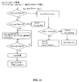
本発明のもう一つの実施例にしたがって、図11は機械式エンジンのエンジンスピード変換プロセスを示した流れのダイアグラムである。(電子式エンジンスピードはデータリンクから直接に読み取られる。この実施例においては、エンジンスピードはバッファーのキャプチャーモードで16ビットのフリーランニングカウンターを使って計測される。外部パルスはカウンターの最新値を検索し、それをキャプチャーレジスターに記憶する。前にキャプチャーレジスターに残っているバリュー(値)はバッファーレジスターに移される。キャプチャーイベントが発生したことを示すフラグが現れる。get rpm( )(図11に示されている)機能は、バッファーレジスターの前のキャプチャー値、キャプチャーレジスターの新しいキャプチャー値、カウンター周波数、そしてフライフィールの歯を使って、r.p.m.を計算するアルゴリズムを含んでいる。この機能は、2ミリ秒毎に、同期式制御エグゼクティブの中から呼び出される。 In accordance with another embodiment of the present invention, FIG. 11 is a flow diagram illustrating an engine speed conversion process for a mechanical engine. (The electronic engine speed is read directly from the data link. In this example, the engine speed is measured using a 16-bit free-running counter in buffer capture mode. External pulses retrieve the latest value of the counter. And store it in the capture register, the value previously left in the capture register is moved to the buffer register, and a flag appears indicating that a capture event has occurred. The rpm () function (shown in FIG. 11) includes an algorithm that calculates the rpm using the previous capture value in the buffer register, the new capture value in the capture register, the counter frequency, and the fly feel teeth. Yes. This function is called from within the synchronous control executive every 2 milliseconds.
エンジン変換アルゴリズムは又、入力信号の周波数が低くなりすぎてカウンターがループしてしまう時間が生じる場合に備えて、障害のある結果に対する保護機能もある。Rpm cap flag(図11参照)は、キャプチャーイベントが見つかったときに現れるキャプチャーフラッグである。機能が実行され、キャプチャーが見付からないときは、「acm」値は増分される。もしキャプチャーが『acm max』タイム中に見つからない場合は、rpmはゼロと見なされる。フライフィールの120歯と、とacm max値が4に設定された場合、最小測定可能rpmは約60である。 The engine conversion algorithm also provides protection against faulty results in case the frequency of the input signal becomes too low causing the counter to loop. Rpm cap The flag (see FIG. 11) is a capture flag that appears when a capture event is found. When the function is executed and no capture is found, the “acm” value is incremented. If the capture is acm If not found during the “max” time, rpm is considered zero. 120 teeth of fly feel and acm If the max value is set to 4, the minimum measurable rpm is about 60.
また他の実施例にしたがって、図12は、ガス制御機能の流れの典型的なダイアグラムを表している。システムが、既存の機械式調整器を取り除くことなくインストールされているため、二重燃料機関のスピード制御特性は、機械式調整器によるものより高くはないが、近い形でプログラムされるのが望ましい。機械式制御特性は、システムが較正されるとき、tps map と呼ばれるECUマップの中に記憶される。マップはr.p.m.の範囲を通じて複数のバリューを有する。安定性の理由から、オフセットが、図12に示されている様に、特性に適用される。適用されるオフセットは、通常20から200r.p.m.である。別個のアルゴリズムが、低いアイドル(空転)のとき、エンジンを制御する。その機能によって使われるr.p.m.リファレンスは図12に示されているように設定されるであろう。 In accordance with yet another embodiment, FIG. 12 depicts a typical diagram of the flow of gas control functions. Because the system is installed without removing the existing mechanical regulator, the speed control characteristics of the dual fuel engine are not higher than those with the mechanical regulator, but should be programmed closely. . Mechanical control characteristics are tps when the system is calibrated It is stored in an ECU map called map. The map has multiple values throughout the rpm range. For reasons of stability, an offset is applied to the characteristic as shown in FIG. The applied offset is usually 20 to 200 rpm. A separate algorithm controls the engine when it is low idle. The rpm reference used by that function will be set as shown in FIG.
異なったPID設定が安定性の理由からPTOモードで使われるであろう。ガス燃料制限はエンジンが燃料超過になるのを防ぐために適用される。燃料制限カーブは32r.p.m.毎につき1ポイントでEEPROMメモリーに記憶される。バリュー(値)の範囲は普通、インジェクターパルスの0から90%の範囲に対応して、0から27000になる。或るr.p.m.では、プログラムは2つの隣り合う燃料カーブポイントを読みとり、直線内挿のインターポレイションを使って燃料制限を計算する。燃料制限はさらに、ブースト、ガス圧力、ガス温度を考慮に入れて再計算される。最終的には、PID速度制御に加えて、燃料制御特性を規定して、燃料制限はスロットルポジションのパーセンテージを掛け算される。 Different PID settings will be used in PTO mode for stability reasons. Gas fuel limits are applied to prevent the engine from becoming overfueled. The fuel limit curve is stored in the EEPROM memory at one point for every 32 r.p.m. The value range is usually from 0 to 27000, corresponding to a range of 0 to 90% of the injector pulse. At some r.p.m., the program reads two adjacent fuel curve points and calculates the fuel limit using linear interpolation. The fuel limit is further recalculated taking into account boost, gas pressure, and gas temperature. Ultimately, in addition to PID speed control, fuel control characteristics are defined, and the fuel limit is multiplied by the percentage of throttle position.
計算されたバリュー(値)は、一度に1インジェクターの割合で、インジェクターに指定される。もしマニホルドインジェクターが使われるならば、インジェクターは、図13に示されているように順番に作動する。使用される最大インジェクターパルス幅は90%である。 The calculated value is assigned to the injector at a rate of one injector at a time. If a manifold injector is used, the injectors operate in sequence as shown in FIG. The maximum injector pulse width used is 90%.
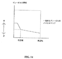
図14は、機械式エンジン用の一般的なディーゼルパイロットマップである。このマップは、ポンプ上のディーゼルパイロットレバーの位置が、エンジンに負荷がない時は低い空転(アイドル)で、エンジンに負荷がある時は高い空転であることを表す。示されているように、ディーゼルの供給は、低い空転ではエンジンストールを避けるために増加し、高い空転では減少する。ディーゼルパイロット制御機能(図9)は、ディーゼル燃料供給は較正の間、EEPROMメモリーの中に記録されているディーゼル燃料マップに従うことを確実にする。ある特別な実施例では、燃料マップは128ポイントを持つ。 FIG. 14 is a typical diesel pilot map for a mechanical engine. This map indicates that the position of the diesel pilot lever on the pump is low idling when the engine is not loaded and is idling when the engine is loaded. As shown, the diesel supply increases to avoid engine stall at low idle and decreases at high idle. The diesel pilot control function (FIG. 9) ensures that the diesel fuel supply follows the diesel fuel map recorded in the EEPROM memory during calibration. In one particular embodiment, the fuel map has 128 points.
図15は電子式エンジン用ECUソフトウェアの構造を示す。これらのシステムでは、ECUは、SAEJ1939データリンク経由でOEMコントローラーに接続され、既存のセンサーを利用し、OEMコントローラーを通してディーゼル燃料供給への制御を実行している。 FIG. 15 shows the structure of the electronic engine ECU software. In these systems, the ECU is connected to the OEM controller via the SAEJ 1939 data link and utilizes existing sensors to control the diesel fuel supply through the OEM controller.
電子式システム用のECUソフトウェアは機械式ソフトウェア同じ様な構造をしている。しかしながら、車の速度、エンジンスピード、冷却剤温度、環境温度と圧力の如き、いくつかの重要なエンジンパラメーター、そしてマニホルド温度と圧力は、ECU専用センサーから読み取ることなくデータリンクから得ることができる。ECUは必要なディーゼル燃料のパーセンテージを決定し、このレベルにディーゼル燃料を制限するよう要求する。 ECU software for electronic systems has the same structure as mechanical software. However, some important engine parameters, such as vehicle speed, engine speed, coolant temperature, ambient temperature and pressure, and manifold temperature and pressure can be obtained from the data link without reading from ECU dedicated sensors. The ECU determines the percentage of diesel fuel required and requests that the diesel fuel be limited to this level.
ECUの中のCANモジュールは、通信にメールボックスを使う。メールボックスは、次の表に示されているように、様々なJ1939のパラメーター群を受信したり伝送するために、ECU初期化の間に形成される。ほかのパラメーターもまた、有用性に応じて、受信されている。

複数燃料機関への改変は完成するのに約一日かかる。それはとりわけ、軽量級、中級、重量級のディーゼルとガソリンエンジンであって、オンロードとオフロードの両方に対する改変、市場後の機械式及び電気式エンジンの旧式への適用、または直接噴射のディーゼル又はガソリンエンジンであって、ターボチャージ及び自然噴射の両方に対する改変に、使用されてもよい。 The modification to a multiple fuel engine takes about a day to complete. Among other things, lightweight, intermediate and heavy duty diesel and gasoline engines, both on-road and off-road modifications, post-market mechanical and electric engine old-fashioned applications, or direct injection diesel or A gasoline engine may be used to modify both turbocharge and natural injection.
この発明の特別な実施例が図示のため上に述べられているが、技術知識のある人には、本発明の細かい部分の数多くの変更は、添付の請求の範囲に定められているこの発明から外れることなく、作り得ることが明らかであろう。 While specific embodiments of the invention have been described above by way of illustration, to those skilled in the art, many changes in the details of the invention may be found in the appended claims. It will be clear that it can be made without deviating from the above.
Claims (45)
a.エンジンシステムの作動特性を電子制御装置に入力する手段であって、少なくとも1つの作動特性は、第二燃料のガス圧力、第二燃料のガス温度、吸気マニホルドのブースト圧力又はエンジン冷却剤温度を有しており、及び
b.作動特性に基づいて、複数燃料機関への第一燃料及び第二燃料の供給量を制御する手段、
を含んでいる、電子制御装置。 An electronic control unit for a multiple fuel engine using a first fuel and a second fuel, the electronic control unit comprising:
a. Means for inputting engine system operating characteristics to an electronic control unit, wherein at least one operating characteristic includes second fuel gas pressure, second fuel gas temperature, intake manifold boost pressure, or engine coolant temperature. And b. Means for controlling the supply amounts of the first fuel and the second fuel to the plurality of fuel engines based on the operating characteristics;
Including an electronic control unit.
b.支配するための特性に基づいて、複数燃料機関への第一燃料及び第二燃料の供給量を制御する手段、
をさらに含んでいる、請求項1に記載の電子制御装置。 a. Means for determining characteristics to govern control of multiple fuels based on operating characteristics of the engine system; and b. Means for controlling the supply amounts of the first fuel and the second fuel to the plurality of fuel engines based on the characteristic to control;
The electronic control device according to claim 1, further comprising:
a.電子制御装置を提供すること、
b.エンジンシステムの作動特性を電子制御装置に入力することであって、少なくとも1つの作動特性には、第二燃料のガス圧力、第二燃料のガス温度、吸気マニホルドのブースト圧力又はエンジン冷却剤温度が含まれること、及び
c.作動特性に基づいて、複数燃料機関への第一燃料及び第二燃料の供給量を制御すること、
を含んでいる、複数燃料機関への燃料供給量を制御する方法。 A method for controlling a fuel supply amount to a multiple fuel engine using a first fuel and a second fuel, the method comprising:
a. Providing an electronic control unit,
b. Inputting an operating characteristic of the engine system to the electronic controller, wherein at least one of the operating characteristics includes a second fuel gas pressure, a second fuel gas temperature, an intake manifold boost pressure or an engine coolant temperature. Inclusion, and c. Controlling the supply amount of the first fuel and the second fuel to the multiple fuel engine based on the operating characteristics;
A method for controlling a fuel supply amount to a multiple fuel engine.
b.作動特性に基づいて、複数燃料機関への第一燃料及び第二燃料の供給量を制御すること、
をさらに含んでいる請求項21に記載の方法。 a. Determining characteristics to govern control of multiple fuels based on operating characteristics of the engine system; and b. Controlling the supply amount of the first fuel and the second fuel to the multiple fuel engine based on the operating characteristics;
The method of claim 21, further comprising:
a.エンジンシステムの作動特性を電子制御装置に入力すること、
b.エンジンシステムの作動特性に基づいて、複数燃料の制御を支配するための特性を決定する手段、及び
c.作動特性に基づいて、複数燃料機関への第一燃料及び第二燃料の供給量を制御すること、
を含んでいる方法。 A method of calibrating an electronic controller for a multiple fuel engine using a first fuel and a second fuel, the method comprising:
a. Inputting the operating characteristics of the engine system into the electronic control unit;
b. Means for determining characteristics to govern control of multiple fuels based on operating characteristics of the engine system; and c. Controlling the supply amount of the first fuel and the second fuel to the multiple fuel engine based on the operating characteristics;
Including methods.
a.エンジンシステムの作動特性を電子制御装置に入力する手段であって、少なくとも1つの作動特性には、第二燃料のガス圧力、第二燃料のガス温度、吸気マニホルドのブースト圧力又はエンジン冷却剤温度が含まれる手段、及び
b.作動特性に基づいて、複数燃料機関への第一燃料及び第二燃料の供給量を制御する手段、を含んでいる、
複数燃料機関に改変させる方法。 A method of modifying a vehicle engine system to a multiple fuel engine using a first fuel and a second fuel, the method comprising mounting an electronic control device on the vehicle, the electronic control device comprising:
a. Means for inputting engine system operating characteristics to an electronic controller, wherein at least one operating characteristic includes a second fuel gas pressure, a second fuel gas temperature, an intake manifold boost pressure or an engine coolant temperature; Means included; and b. Means for controlling a supply amount of the first fuel and the second fuel to the plurality of fuel engines based on the operating characteristics,
A method of modifying a multiple fuel engine.
a.作動特性を電子制御装置に入力する手段であって、少なくとも1つの作動特性には、第二燃料のガス圧力、第二燃料のガス温度、吸気マニホルドのブースト圧力又はエンジン冷却剤温度が含まれる、及び
b.少なくとも1つの作動特性に基づいて、複数燃料機関への第一燃料及び第二燃料の供給量を制御する手段、
を含んでいる、複数燃料エンジンシステム。 A multi-fuel engine system using a first fuel and a second fuel, wherein the multi-fuel engine system can be distributed between the engine, a first fuel storage tank, a first fuel tank and the engine. A first fuel tank, a second fuel storage tank, a second fuel tank that can be circulated between the second fuel tank and the engine, and an electronic control device, the electronic control device comprising:
a. Means for inputting operating characteristics to the electronic control unit, wherein the at least one operating characteristic includes a gas pressure of the second fuel, a gas temperature of the second fuel, a boost pressure of the intake manifold, or an engine coolant temperature; And b. Means for controlling a supply amount of the first fuel and the second fuel to the multiple fuel engine based on at least one operating characteristic;
Including a multiple fuel engine system.
b.作動特性に基づいて、複数燃料の制御のための作動特性を決定すること、及び
c.作動特性に基づいて、エンジンへの第一燃料及び第二燃料の供給量を制御すること、を含んでいる、
指示を含むコンピュータ読取可能メディア。 A computer readable medium containing instructions for performing a method of operating a multi-fuel engine that uses a first fuel and a second fuel when executed by a processor, the method comprising:
b. Determining operating characteristics for control of multiple fuels based on the operating characteristics; and c. Controlling a supply amount of the first fuel and the second fuel to the engine based on the operating characteristics,
A computer readable medium containing instructions.
45. The computer readable medium of claim 44, wherein at least one of the operating characteristics includes a second fuel gas pressure, a second fuel gas temperature, an intake manifold boost pressure, or an engine coolant temperature.
Applications Claiming Priority (2)
| Application Number | Priority Date | Filing Date | Title |
|---|---|---|---|
| US41326902P | 2002-09-24 | 2002-09-24 | |
| PCT/US2003/029914 WO2004029438A1 (en) | 2002-09-24 | 2003-09-23 | Methods and apparatus for operation of multiple fuel engines |
Publications (1)
| Publication Number | Publication Date |
|---|---|
| JP2006500513A true JP2006500513A (en) | 2006-01-05 |
Family
ID=32043226
Family Applications (1)
| Application Number | Title | Priority Date | Filing Date |
|---|---|---|---|
| JP2004540174A Pending JP2006500513A (en) | 2002-09-24 | 2003-09-23 | Method and apparatus for operating multiple fuel engines |
Country Status (13)
| Country | Link |
|---|---|
| US (2) | US7222015B2 (en) |
| EP (1) | EP1546532B1 (en) |
| JP (1) | JP2006500513A (en) |
| CN (1) | CN100414082C (en) |
| AT (1) | ATE448397T1 (en) |
| AU (1) | AU2003275148A1 (en) |
| BR (1) | BR0314685A (en) |
| CA (1) | CA2499936A1 (en) |
| CO (1) | CO5721028A2 (en) |
| DE (1) | DE60330032D1 (en) |
| EC (1) | ECSP055744A (en) |
| MX (1) | MXPA05003204A (en) |
| WO (1) | WO2004029438A1 (en) |
Cited By (2)
| Publication number | Priority date | Publication date | Assignee | Title |
|---|---|---|---|---|
| JP2013079652A (en) * | 2007-09-18 | 2013-05-02 | T Baden Hardstaff Ltd | Dual fuel engine control unit |
| CN104271926A (en) * | 2012-05-11 | 2015-01-07 | 瓦锡兰芬兰有限公司 | Method for operating a dual fuel engine |
Families Citing this family (139)
| Publication number | Priority date | Publication date | Assignee | Title |
|---|---|---|---|---|
| WO2005064144A1 (en) * | 2003-12-30 | 2005-07-14 | Kruger Ventures Pty Ltd | Compression ignition engine improvements |
| US7101312B2 (en) * | 2004-04-23 | 2006-09-05 | General Motors Corporation | Vehicular power take-off control |
| FR2870294B1 (en) * | 2004-05-12 | 2008-04-18 | Peugeot Citroen Automobiles Sa | SYSTEM FOR MONITORING THE OPERATION OF A MOTOR VEHICLE THERMAL MOTOR |
| US7206720B2 (en) * | 2005-02-24 | 2007-04-17 | Lapant Todd | Computer-controlled auxiliary fuel tank system with multi-function monitoring system and user calibration capabilities |
| WO2007006069A1 (en) * | 2005-07-14 | 2007-01-18 | Dga (Ip) Pty Ltd | Apparatus and method for diesel engine fumigation |
| KR100747210B1 (en) * | 2005-08-30 | 2007-08-07 | 현대자동차주식회사 | LPI engine system |
| JP3976057B2 (en) * | 2005-10-28 | 2007-09-12 | いすゞ自動車株式会社 | Engine control device |
| CA2538980C (en) * | 2006-03-10 | 2008-09-23 | Westport Research Inc. | Method and apparatus for operating a dual fuel internal combustion engine |
| EP2013461A1 (en) * | 2006-04-12 | 2009-01-14 | Clean Air Power Limited | Gas and diesel powered compression ignition engine |
| US7953530B1 (en) * | 2006-06-08 | 2011-05-31 | Pederson Neal R | Vehicle diagnostic tool |
| DE102007009546B4 (en) * | 2007-02-27 | 2008-12-04 | Continental Automotive Gmbh | Method and device for controlling an internal combustion engine of a motor vehicle which can be switched to operation with CNG gas |
| DE102007022230A1 (en) | 2007-05-09 | 2008-11-13 | Ecomotec Gmbh | Self igniting-internal combustion engine operating method for use in motor vehicle i.e. truck, involves selecting partial desired value and amount of fuel in such manner that amount of fuel is supplied to engine is larger |
| US20090076705A1 (en) * | 2007-09-13 | 2009-03-19 | Colesworthy Robert L | Power modulated, dual fuel, small displacement engine control system |
| CN103122800B (en) * | 2007-10-27 | 2016-01-20 | 沃尔布罗发动机使用有限责任公司 | Engine fuel delivery systems, equipment and method |
| US7703528B2 (en) | 2008-01-15 | 2010-04-27 | Halliburton Energy Services, Inc. | Reducing CO2 emissions from oilfield diesel engines |
| US7950370B2 (en) * | 2008-03-13 | 2011-05-31 | Cummins Inc. | High pressure common rail fuel system with gas injection |
| DE102008019225B4 (en) * | 2008-04-17 | 2017-10-05 | Audi Ag | Method for cold start operation of an internal combustion engine |
| US20090272096A1 (en) * | 2008-05-05 | 2009-11-05 | General Electric Company | Single Manifold Dual Gas Turbine Fuel System |
| JP4624448B2 (en) * | 2008-07-30 | 2011-02-02 | 株式会社オートネットワーク技術研究所 | Control device, control system, and computer program |
| WO2010059081A1 (en) * | 2008-11-20 | 2010-05-27 | Volvo Lastvagnar Ab | Method and apparatus for operation of a multiple fuel engine |
| GB0901903D0 (en) * | 2009-02-05 | 2009-03-11 | T Baden Hardstaff Ltd | A fuel injection system |
| JP2012520418A (en) * | 2009-03-13 | 2012-09-06 | ティー. バーデン ハードスタッフ リミテッド | Method and control device for controlling an engine |
| CN102549251B (en) * | 2009-04-20 | 2016-02-03 | 工业私人有限公司 | For the double fuel supply system of diesel motor indirect injection system |
| GB0907614D0 (en) | 2009-05-01 | 2009-06-10 | Intelligent Diesel Systems Ltd | Apparatus and method for controlling a multi-fuel engine |
| US8275538B2 (en) * | 2009-06-12 | 2012-09-25 | Ford Global Technologies, Llc | Multi-fuel engine starting control system and method |
| US8413643B2 (en) * | 2009-06-12 | 2013-04-09 | Ford Global Tehnologies, LLC | Multi-fuel engine control system and method |
| US7913673B2 (en) * | 2009-06-30 | 2011-03-29 | Clean Air Power, Inc. | Method and apparatus for controlling liquid fuel delivery during transition between modes in a multimode engine |
| HUP0900736A2 (en) | 2009-11-27 | 2011-08-29 | Ferenc Molnar | Equipment and process for electronically controlled injection of liquified or compressed gas into diesel engines |
| US20120004824A1 (en) * | 2009-11-30 | 2012-01-05 | Trevor Robert Milton | Natural gas and diesel fuel blending system |
| US9065300B2 (en) * | 2009-12-04 | 2015-06-23 | Kevin R. Williams | Dual fuel system and method of supplying power to loads of a drilling rig |
| US20110166769A1 (en) * | 2010-01-07 | 2011-07-07 | Jeffrey Douglas Buechler | Supplemental Vapor Fuel Injection System for Internal Combustion Engines |
| AT11331U3 (en) * | 2010-01-14 | 2011-01-15 | Avl List Gmbh | METHOD AND DEVICE FOR CALIBRATING A TORQUE MEASUREMENT DEVICE |
| JP5401352B2 (en) * | 2010-02-05 | 2014-01-29 | 株式会社ケーヒン | Fuel switching control device and method |
| WO2011130791A1 (en) * | 2010-04-20 | 2011-10-27 | Dgc Industries Pty Ltd | A dual fuel supply system for a direct-injection system of a diesel engine with on-board mixing |
| WO2012051122A2 (en) * | 2010-10-10 | 2012-04-19 | Bex America, Llc | Method and apparatus for converting diesel engines to blended gaseous and diesel fuel engines |
| AU2010352515A1 (en) * | 2010-10-29 | 2012-05-24 | Gastech Engine & Equipment Pty. Ltd. | Cooling Systems for Gas Fuel Engines |
| GB2488814A (en) * | 2011-03-09 | 2012-09-12 | Mobilizer Ltd | Engine Performance Modification or Tuning Kit |
| US20120239279A1 (en) * | 2011-03-15 | 2012-09-20 | Aaron Stuart | Fuel control module mapping system, method and apparatus for bi-fuel and dual fuel vehicles |
| US9104443B2 (en) * | 2011-03-31 | 2015-08-11 | GM Global Technology Operations LLC | Control software with programmable arrays that are configurable for vehicles having different propulsion system configurations |
| US20120266846A1 (en) * | 2011-04-25 | 2012-10-25 | Michael Kilbourne | Dual fuel diesel engine system |
| CN102269062B (en) * | 2011-05-10 | 2014-08-06 | 崔万秀 | Multi-fuel diesel oil combustion system of heavy equipment and device thereof |
| WO2013003888A1 (en) * | 2011-07-04 | 2013-01-10 | Orbital Australia Pty Ltd | Gaseous metering control for dual fluid injector |
| US8794212B2 (en) * | 2011-07-29 | 2014-08-05 | General Electric Company | Engine and method of operating engine |
| US9169789B2 (en) * | 2011-08-15 | 2015-10-27 | GM Global Technology Operations LLC | System and method for adjusting fuel mass for minimum fuel injector pulse widths in multiple fuel system engines |
| US9097224B2 (en) | 2011-08-15 | 2015-08-04 | GM Global Technology Operations LLC | Multi-fuel vehicle fuel control systems and methods |
| CN102392740B (en) * | 2011-08-24 | 2014-12-24 | 中国南方航空工业(集团)有限公司 | Oil feeding device and oil feeding method |
| DE102011088497A1 (en) * | 2011-12-14 | 2013-06-20 | Robert Bosch Gmbh | Method for operating a multi-fuel internal combustion engine by means of two control units and operating according to the inventive method multi-fuel internal combustion engine |
| US20160222895A1 (en) * | 2011-12-16 | 2016-08-04 | General Electric Company | Multi-fuel system and method |
| US9309819B2 (en) | 2012-11-14 | 2016-04-12 | General Electric Company | Multi-fuel system and method |
| US20160153375A1 (en) * | 2012-05-31 | 2016-06-02 | General Electric Company | Method for operating an engine |
| US8682512B2 (en) * | 2011-12-16 | 2014-03-25 | General Electric Company | Fuel optimizing system for a mobile asset, and a related method thereof |
| US9157385B2 (en) * | 2011-12-16 | 2015-10-13 | General Electric Company | Fuel selection method and related system for a mobile asset |
| US11643986B2 (en) * | 2011-12-16 | 2023-05-09 | Transportation Ip Holdings, Llc | Multi-fuel system and method |
| US10344687B2 (en) * | 2011-12-16 | 2019-07-09 | Ge Global Sourcing Llc | Fuel selection method and related system for a mobile asset |
| US11905897B2 (en) * | 2011-12-16 | 2024-02-20 | Transportation Ip Holdings, Llc | Fuel selection method and related system for a mobile asset |
| US9422900B2 (en) * | 2012-03-27 | 2016-08-23 | Ford Global Technologies, Llc | System and method for closing a tank valve |
| CA2773651C (en) | 2012-04-05 | 2013-04-09 | Westport Power Inc. | Method and apparatus for controlling fuel pressure in a gaseous fuelled internal combustion engine |
| US9234452B2 (en) | 2012-05-17 | 2016-01-12 | Caterpillar Inc. | Direct injection gas engine and method |
| US11578684B2 (en) | 2012-05-31 | 2023-02-14 | Transportation Ip Holdings, Llc | Method for operating an engine |
| WO2013182316A1 (en) * | 2012-06-08 | 2013-12-12 | Globo Hydro Power Gmbh | Internal combustion engine |
| CN102787921A (en) * | 2012-07-25 | 2012-11-21 | 周继光 | Mixed combustion engine electric control system and control method thereof |
| US9115664B2 (en) | 2012-08-22 | 2015-08-25 | Cummins Inc. | Engine control systems and methods |
| US9228510B2 (en) | 2012-08-22 | 2016-01-05 | Cummins Inc. | Engine control systems and methods |
| US20140060492A1 (en) * | 2012-08-28 | 2014-03-06 | Walter Albert Woolvett | Method for modifying a vehicle to receive and utilize a secondary fuel |
| EP2917543B1 (en) * | 2012-11-09 | 2016-09-14 | Volvo Truck Corporation | A method of conditioning a particle filter |
| US9488114B2 (en) | 2012-11-15 | 2016-11-08 | Caterpillar Inc. | Control strategy for dual gaseous and liquid fuel internal combustion engine |
| US9188069B2 (en) | 2012-12-27 | 2015-11-17 | Caterpillar Inc. | Gaseous fuel system, direct injection gas engine system, and method |
| EP3409915B1 (en) * | 2013-01-09 | 2020-12-23 | Mac Donald, John, Joseph | System and method for improving performance of combustion engines employing primary and secondary fuels |
| WO2014133819A1 (en) * | 2013-02-26 | 2014-09-04 | Cummins Ip, Inc. | System and method for dual fuel engines |
| DE102013213349B4 (en) * | 2013-03-28 | 2017-10-05 | Mtu Friedrichshafen Gmbh | Method for operating a dual-fuel internal combustion engine, control for a dual-fuel internal combustion engine and dual-fuel internal combustion engine |
| DE112013007111B4 (en) * | 2013-05-24 | 2022-12-01 | International Engine Intellectual Property Company, Llc | EGR system for hydrogen-rich exhaust gas and method |
| DE102013009147B4 (en) * | 2013-05-31 | 2015-11-05 | Mtu Friedrichshafen Gmbh | Method for regulating a pressure and arrangement for regulating a pressure |
| US9371789B2 (en) | 2013-06-20 | 2016-06-21 | Cummins Inc. | System and method for a self-adjusting dual fuel gas control |
| US20150000630A1 (en) * | 2013-06-26 | 2015-01-01 | Caterpillar Inc. | Rapid LNG Engine Warm-Up Utilizing Engine Compression Brakes |
| CA2819721C (en) * | 2013-06-27 | 2014-07-08 | Westport Power Inc. | Engine control apparatus |
| DE102014211323B4 (en) * | 2013-07-17 | 2019-03-21 | Ford Global Technologies, Llc | Method for operating an internal combustion engine, internal combustion engine and motor vehicle with improved tractive power at low speeds |
| US20150027406A1 (en) * | 2013-07-25 | 2015-01-29 | Douglas A. Cooper | Adjustable fuel trim module for diesel engine |
| WO2015054657A1 (en) | 2013-10-10 | 2015-04-16 | Cummins Inc. | Fuel control for dual fuel engines |
| CN103498732B (en) * | 2013-10-23 | 2016-02-24 | 深圳市国炬天然气汽车技术有限公司 | Diesel/natural gas dual-fuel internal-combustion engine control oil system |
| CN105683548B (en) | 2013-11-01 | 2019-05-31 | 卡明斯公司 | For realizing the engine control system and method for torque value |
| CN105765203B (en) * | 2013-11-22 | 2019-07-02 | 西港电力公司 | Control system for flexible fuel internal combustion engine |
| BR112016013644A2 (en) * | 2013-12-12 | 2017-08-08 | Mosaic Tech Development Pty Ltd | VEHICLE FUEL SYSTEM |
| RU2578770C1 (en) * | 2014-03-25 | 2016-03-27 | Федеральное государственное бюджетное образовательное учреждение высшего профессионального образования "Владимирский государственный университет имени Александра Григорьевича и Николая Григорьевича Столетовых" (ВлГУ) | Fuel supply system to the combustor gas diesel |
| CN104033256B (en) * | 2014-05-06 | 2016-06-01 | 南京盖驰动力科技有限公司 | The Controlling System of the oil gas dual-fuel engine of mechanical pump fuel feeding and control method thereof |
| US9599040B2 (en) | 2014-05-28 | 2017-03-21 | Caterpillar Motoren Gmbh & Co. Kg | Fuel apportionment for multi fuel engine system |
| WO2015181436A1 (en) * | 2014-05-30 | 2015-12-03 | Wärtsilä Finland Oy | A fuel tank arrangement of a marine vessel and method of operating a tank container of a marine vessel |
| US9689333B2 (en) * | 2014-07-28 | 2017-06-27 | Cummins Inc. | Dual-fuel engine with enhanced cold start capability |
| US9970363B2 (en) * | 2014-08-05 | 2018-05-15 | Jahangir Ahmadi Ardebili poor | After-market gaseous fuel and petrol engine conversion system |
| DE102014216874B4 (en) * | 2014-08-25 | 2018-02-22 | Mtu Friedrichshafen Gmbh | Method for operating an internal combustion engine and internal combustion engine |
| WO2016073588A1 (en) | 2014-11-04 | 2016-05-12 | Cummins Inc. | Systems, methods, and apparatus for operation of dual fuel engines |
| BR102014031629A2 (en) * | 2014-12-17 | 2016-07-26 | Bosch Do Brasil | control process of a combustion engine and engine control unit |
| US20160201627A1 (en) * | 2015-01-09 | 2016-07-14 | Caterpillar Inc. | Gas Fuel System Sizing for Dual Fuel Engines |
| US10287943B1 (en) * | 2015-12-23 | 2019-05-14 | Clean Power Technologies, LLC | System comprising duel-fuel and after treatment for heavy-heavy duty diesel (HHDD) engines |
| CN105697161B (en) * | 2016-02-03 | 2018-06-15 | 福州大学 | A kind of LNG/ Diesel Dual-Fuel Engines control system |
| EP3282111B1 (en) * | 2016-08-11 | 2020-07-01 | Caterpillar Motoren GmbH & Co. KG | Method for starting a gaseous fuel combustion engine |
| WO2018085464A2 (en) * | 2016-11-01 | 2018-05-11 | Yaw Obeng | System and method for operating an engine with reduced nox emissions |
| US9752515B1 (en) | 2017-04-03 | 2017-09-05 | James A. Stroup | System, method, and apparatus for injecting a gas in a diesel engine |
| US11624326B2 (en) | 2017-05-21 | 2023-04-11 | Bj Energy Solutions, Llc | Methods and systems for supplying fuel to gas turbine engines |
| US20190024616A1 (en) * | 2017-07-18 | 2019-01-24 | Svmtech, Llc | Alternative fuel retrofit kit for a combustion engine |
| US10641755B2 (en) * | 2017-12-01 | 2020-05-05 | Toyota Motor Engineering & Manufacturing North America, Inc. | Fuel sending unit for fuel-type detection |
| US11098663B2 (en) | 2018-03-19 | 2021-08-24 | Hydrolyze, LLC | Systems and methods for delivering fuel to an internal combustion engine |
| US11560845B2 (en) | 2019-05-15 | 2023-01-24 | Bj Energy Solutions, Llc | Mobile gas turbine inlet air conditioning system and associated methods |
| US10763882B1 (en) | 2019-05-21 | 2020-09-01 | Volvo Truck Corporation | Switch interface adapter |
| US10989180B2 (en) | 2019-09-13 | 2021-04-27 | Bj Energy Solutions, Llc | Power sources and transmission networks for auxiliary equipment onboard hydraulic fracturing units and associated methods |
| CA3092829C (en) | 2019-09-13 | 2023-08-15 | Bj Energy Solutions, Llc | Methods and systems for supplying fuel to gas turbine engines |
| US10895202B1 (en) | 2019-09-13 | 2021-01-19 | Bj Energy Solutions, Llc | Direct drive unit removal system and associated methods |
| US11002189B2 (en) | 2019-09-13 | 2021-05-11 | Bj Energy Solutions, Llc | Mobile gas turbine inlet air conditioning system and associated methods |
| US11015536B2 (en) | 2019-09-13 | 2021-05-25 | Bj Energy Solutions, Llc | Methods and systems for supplying fuel to gas turbine engines |
| CA3092868A1 (en) | 2019-09-13 | 2021-03-13 | Bj Energy Solutions, Llc | Turbine engine exhaust duct system and methods for noise dampening and attenuation |
| US11015594B2 (en) | 2019-09-13 | 2021-05-25 | Bj Energy Solutions, Llc | Systems and method for use of single mass flywheel alongside torsional vibration damper assembly for single acting reciprocating pump |
| CA3092865C (en) | 2019-09-13 | 2023-07-04 | Bj Energy Solutions, Llc | Power sources and transmission networks for auxiliary equipment onboard hydraulic fracturing units and associated methods |
| CA3197583A1 (en) | 2019-09-13 | 2021-03-13 | Bj Energy Solutions, Llc | Fuel, communications, and power connection systems and related methods |
| US10815764B1 (en) | 2019-09-13 | 2020-10-27 | Bj Energy Solutions, Llc | Methods and systems for operating a fleet of pumps |
| US11604113B2 (en) | 2019-09-13 | 2023-03-14 | Bj Energy Solutions, Llc | Fuel, communications, and power connection systems and related methods |
| RU199244U1 (en) * | 2020-01-31 | 2020-08-24 | федеральное государственное бюджетное образовательное учреждение высшего образования "Ульяновский государственный университет" | Gas-diesel engine power supply unit with component preparation system |
| US11708829B2 (en) | 2020-05-12 | 2023-07-25 | Bj Energy Solutions, Llc | Cover for fluid systems and related methods |
| US10968837B1 (en) | 2020-05-14 | 2021-04-06 | Bj Energy Solutions, Llc | Systems and methods utilizing turbine compressor discharge for hydrostatic manifold purge |
| US11428165B2 (en) | 2020-05-15 | 2022-08-30 | Bj Energy Solutions, Llc | Onboard heater of auxiliary systems using exhaust gases and associated methods |
| CN111577472B (en) * | 2020-05-28 | 2022-04-19 | 广西玉柴机器股份有限公司 | Fuel control method and system of gas engine |
| US11208880B2 (en) | 2020-05-28 | 2021-12-28 | Bj Energy Solutions, Llc | Bi-fuel reciprocating engine to power direct drive turbine fracturing pumps onboard auxiliary systems and related methods |
| US10961908B1 (en) | 2020-06-05 | 2021-03-30 | Bj Energy Solutions, Llc | Systems and methods to enhance intake air flow to a gas turbine engine of a hydraulic fracturing unit |
| US11208953B1 (en) | 2020-06-05 | 2021-12-28 | Bj Energy Solutions, Llc | Systems and methods to enhance intake air flow to a gas turbine engine of a hydraulic fracturing unit |
| US11109508B1 (en) | 2020-06-05 | 2021-08-31 | Bj Energy Solutions, Llc | Enclosure assembly for enhanced cooling of direct drive unit and related methods |
| US11022526B1 (en) | 2020-06-09 | 2021-06-01 | Bj Energy Solutions, Llc | Systems and methods for monitoring a condition of a fracturing component section of a hydraulic fracturing unit |
| US11111768B1 (en) | 2020-06-09 | 2021-09-07 | Bj Energy Solutions, Llc | Drive equipment and methods for mobile fracturing transportation platforms |
| US11066915B1 (en) | 2020-06-09 | 2021-07-20 | Bj Energy Solutions, Llc | Methods for detection and mitigation of well screen out |
| US10954770B1 (en) | 2020-06-09 | 2021-03-23 | Bj Energy Solutions, Llc | Systems and methods for exchanging fracturing components of a hydraulic fracturing unit |
| US11933153B2 (en) | 2020-06-22 | 2024-03-19 | Bj Energy Solutions, Llc | Systems and methods to operate hydraulic fracturing units using automatic flow rate and/or pressure control |
| US11125066B1 (en) | 2020-06-22 | 2021-09-21 | Bj Energy Solutions, Llc | Systems and methods to operate a dual-shaft gas turbine engine for hydraulic fracturing |
| US11028677B1 (en) | 2020-06-22 | 2021-06-08 | Bj Energy Solutions, Llc | Stage profiles for operations of hydraulic systems and associated methods |
| US11939853B2 (en) | 2020-06-22 | 2024-03-26 | Bj Energy Solutions, Llc | Systems and methods providing a configurable staged rate increase function to operate hydraulic fracturing units |
| US11466680B2 (en) | 2020-06-23 | 2022-10-11 | Bj Energy Solutions, Llc | Systems and methods of utilization of a hydraulic fracturing unit profile to operate hydraulic fracturing units |
| US11473413B2 (en) | 2020-06-23 | 2022-10-18 | Bj Energy Solutions, Llc | Systems and methods to autonomously operate hydraulic fracturing units |
| US11220895B1 (en) | 2020-06-24 | 2022-01-11 | Bj Energy Solutions, Llc | Automated diagnostics of electronic instrumentation in a system for fracturing a well and associated methods |
| US11149533B1 (en) | 2020-06-24 | 2021-10-19 | Bj Energy Solutions, Llc | Systems to monitor, detect, and/or intervene relative to cavitation and pulsation events during a hydraulic fracturing operation |
| US11193360B1 (en) | 2020-07-17 | 2021-12-07 | Bj Energy Solutions, Llc | Methods, systems, and devices to enhance fracturing fluid delivery to subsurface formations during high-pressure fracturing operations |
| US11639654B2 (en) | 2021-05-24 | 2023-05-02 | Bj Energy Solutions, Llc | Hydraulic fracturing pumps to enhance flow of fracturing fluid into wellheads and related methods |
| US11988175B2 (en) | 2021-09-01 | 2024-05-21 | American CNG, LLC | Supplemental fuel system for compression-ignition engine |
| CN113606050B (en) * | 2021-10-08 | 2022-02-15 | 潍坊力创电子科技有限公司 | Implementation method of marine dual-fuel oil gas multi-point fuel gas injection control system |
Citations (8)
| Publication number | Priority date | Publication date | Assignee | Title |
|---|---|---|---|---|
| JPH0185436U (en) * | 1987-11-30 | 1989-06-06 | ||
| JPH0544526A (en) * | 1991-08-16 | 1993-02-23 | Mazda Motor Corp | Fuel control device for engine |
| US5370097A (en) * | 1993-03-22 | 1994-12-06 | Davis Family Trust | Combined diesel and natural gas engine fuel control system and method of using such |
| JPH0734914A (en) * | 1993-07-19 | 1995-02-03 | Nissan Motor Co Ltd | Fuel supply control device for internal combustion engine |
| JPH11148382A (en) * | 1997-11-14 | 1999-06-02 | Hiraoka Toshihiko | Duplex fuel diesel engine |
| JPH11166432A (en) * | 1997-12-02 | 1999-06-22 | Denso Corp | Two-kind fuel switching controller for internal combustion engine |
| US5937800A (en) * | 1998-03-06 | 1999-08-17 | Caterpillar Inc. | Method for enabling a substantially constant total fuel energy rate within a dual fuel engine |
| JPH11324749A (en) * | 1998-05-08 | 1999-11-26 | Aisan Ind Co Ltd | Fuel supply control system for engine |
Family Cites Families (16)
| Publication number | Priority date | Publication date | Assignee | Title |
|---|---|---|---|---|
| US4603674A (en) * | 1981-06-19 | 1986-08-05 | Yanmar Diesel Engine Co., Ltd. | Gas-diesel dual fuel engine |
| US4463734A (en) * | 1982-05-14 | 1984-08-07 | Akeroyd Richard T | Dual fuel diesel engine |
| NL8203169A (en) * | 1982-08-12 | 1984-03-01 | Tno | SYSTEM FOR USING GAS AS A SECOND FUEL IN DIESEL ENGINES. |
| US5224457A (en) | 1992-02-28 | 1993-07-06 | Deere & Company | Dual fuel electronic control system |
| US5450829A (en) | 1994-05-03 | 1995-09-19 | Servojet Products International | Electronically controlled pilot fuel injection of compression ignition engines |
| US5526786A (en) | 1995-01-23 | 1996-06-18 | Servojet Products International | Dual fuel engine having governor controlled pilot fuel injection system |
| US6230683B1 (en) * | 1997-08-22 | 2001-05-15 | Cummins Engine Company, Inc. | Premixed charge compression ignition engine with optimal combustion control |
| US5999888A (en) | 1997-06-09 | 1999-12-07 | Alternate Energy Corporation | Automated control system for managing multiple energy sources |
| CA2213939C (en) | 1997-08-25 | 2001-12-18 | Alternative Fuel Systems Inc. | Conversion system with electronic controller for utilization of gaseous fuels in spark ignition engines |
| US6073592A (en) | 1998-03-06 | 2000-06-13 | Caterpillar Inc. | Apparatus for an engine control system |
| US6092504A (en) * | 1998-08-04 | 2000-07-25 | Caterpillar Inc. | Device for controlling engine speed using dual governors |
| EP1105634A4 (en) | 1998-08-21 | 2007-05-02 | Orbital Eng Pty | Fuel injection system control method |
| US6543395B2 (en) | 1998-10-13 | 2003-04-08 | Gas Technologies, Inc. | Bi-fuel control system and retrofit assembly for diesel engines |
| US6234149B1 (en) * | 1999-02-25 | 2001-05-22 | Cummins Engine Company, Inc. | Engine control system for minimizing turbocharger lag including altitude and intake manifold air temperature compensation |
| CN2499594Y (en) * | 2002-03-01 | 2002-07-10 | 天津大学 | Gas supply device for diesel and natural gas double fuel engine |
| US6694242B2 (en) * | 2002-03-20 | 2004-02-17 | Clean Air Power, Inc. | Dual fuel engine having multiple dedicated controllers connected by a broadband communications link |
-
2003
- 2003-09-23 AU AU2003275148A patent/AU2003275148A1/en not_active Abandoned
- 2003-09-23 JP JP2004540174A patent/JP2006500513A/en active Pending
- 2003-09-23 US US10/668,589 patent/US7222015B2/en not_active Expired - Lifetime
- 2003-09-23 CA CA002499936A patent/CA2499936A1/en not_active Abandoned
- 2003-09-23 CN CNB038247143A patent/CN100414082C/en not_active Expired - Fee Related
- 2003-09-23 AT AT03759416T patent/ATE448397T1/en not_active IP Right Cessation
- 2003-09-23 WO PCT/US2003/029914 patent/WO2004029438A1/en active Application Filing
- 2003-09-23 EP EP03759416A patent/EP1546532B1/en not_active Expired - Lifetime
- 2003-09-23 MX MXPA05003204A patent/MXPA05003204A/en active IP Right Grant
- 2003-09-23 BR BR0314685-5A patent/BR0314685A/en not_active IP Right Cessation
- 2003-09-23 DE DE60330032T patent/DE60330032D1/en not_active Expired - Lifetime
-
2005
- 2005-03-28 CO CO05026958A patent/CO5721028A2/en not_active Application Discontinuation
- 2005-04-22 EC EC2005005744A patent/ECSP055744A/en unknown
-
2007
- 2007-05-21 US US11/751,192 patent/US7509209B2/en not_active Expired - Lifetime
Patent Citations (8)
| Publication number | Priority date | Publication date | Assignee | Title |
|---|---|---|---|---|
| JPH0185436U (en) * | 1987-11-30 | 1989-06-06 | ||
| JPH0544526A (en) * | 1991-08-16 | 1993-02-23 | Mazda Motor Corp | Fuel control device for engine |
| US5370097A (en) * | 1993-03-22 | 1994-12-06 | Davis Family Trust | Combined diesel and natural gas engine fuel control system and method of using such |
| JPH0734914A (en) * | 1993-07-19 | 1995-02-03 | Nissan Motor Co Ltd | Fuel supply control device for internal combustion engine |
| JPH11148382A (en) * | 1997-11-14 | 1999-06-02 | Hiraoka Toshihiko | Duplex fuel diesel engine |
| JPH11166432A (en) * | 1997-12-02 | 1999-06-22 | Denso Corp | Two-kind fuel switching controller for internal combustion engine |
| US5937800A (en) * | 1998-03-06 | 1999-08-17 | Caterpillar Inc. | Method for enabling a substantially constant total fuel energy rate within a dual fuel engine |
| JPH11324749A (en) * | 1998-05-08 | 1999-11-26 | Aisan Ind Co Ltd | Fuel supply control system for engine |
Cited By (2)
| Publication number | Priority date | Publication date | Assignee | Title |
|---|---|---|---|---|
| JP2013079652A (en) * | 2007-09-18 | 2013-05-02 | T Baden Hardstaff Ltd | Dual fuel engine control unit |
| CN104271926A (en) * | 2012-05-11 | 2015-01-07 | 瓦锡兰芬兰有限公司 | Method for operating a dual fuel engine |
Also Published As
| Publication number | Publication date |
|---|---|
| CO5721028A2 (en) | 2007-01-31 |
| CN1701169A (en) | 2005-11-23 |
| CN100414082C (en) | 2008-08-27 |
| AU2003275148A1 (en) | 2004-04-19 |
| MXPA05003204A (en) | 2005-09-12 |
| CA2499936A1 (en) | 2004-04-08 |
| US7509209B2 (en) | 2009-03-24 |
| ATE448397T1 (en) | 2009-11-15 |
| DE60330032D1 (en) | 2009-12-24 |
| EP1546532A1 (en) | 2005-06-29 |
| ECSP055744A (en) | 2005-08-11 |
| US7222015B2 (en) | 2007-05-22 |
| WO2004029438A1 (en) | 2004-04-08 |
| US20040111210A1 (en) | 2004-06-10 |
| US20070295316A1 (en) | 2007-12-27 |
| BR0314685A (en) | 2005-08-09 |
| EP1546532B1 (en) | 2009-11-11 |
Similar Documents
| Publication | Publication Date | Title |
|---|---|---|
| JP2006500513A (en) | Method and apparatus for operating multiple fuel engines | |
| EP0690957B1 (en) | Combined diesel and natural gas engine fuel control system and method of using such | |
| US7369934B2 (en) | Predictive engine combustion management | |
| EP1170493B1 (en) | Method and system for engine control | |
| EP1548255B1 (en) | Control device for internal combustion engine | |
| KR101251369B1 (en) | Method for controlling a fuel delivering device of an internal combustion engine | |
| EP1936154B1 (en) | Method of operating an internal combustion engine and control system for operation of an internal combustion engine | |
| US20120109499A1 (en) | Method for regulating a gas engine | |
| US20100095929A1 (en) | Method and device for controlling an internal combustion engine | |
| CN101142390B (en) | Control apparatus for internal combustion engine | |
| US7765983B2 (en) | Method and device for controlling an internal combustion engine | |
| CN103573447A (en) | System and method for diagnosing a fault in an oxygen sensor based on engine speed | |
| DE102008063331A1 (en) | A system and method for determining unsampled vehicle operating parameters | |
| US20150027406A1 (en) | Adjustable fuel trim module for diesel engine | |
| US6050243A (en) | Internal combustion engine control | |
| US20180148005A1 (en) | System and Method for Use With a Combustion Engine | |
| Nwagboso | Integrated sensors and control system for engines using gaseous fuels | |
| CN101294520A (en) | System for controlling fuel injectors | |
| Casacci et al. | 5 th Generation Electronic Gas Injection Control System | |
| JP2000511990A (en) | Method of controlling injection of dual fuel diesel gas engine injection system and related injection system | |
| Davis | Development of an e85 engine for the ecocar challenge hybrid vehicle competition | |
| ITRE20060071A1 (en) | APPARATUS AND METHOD FOR MONITORING THE OPERATION OF AN INTERNAL COMBUSTION ENGINE CONTROLLED BY AN ELECTRONIC CONTROL UNIT |
Legal Events
| Date | Code | Title | Description |
|---|---|---|---|
| A621 | Written request for application examination |
Free format text: JAPANESE INTERMEDIATE CODE: A621 Effective date: 20060718 |
|
| A131 | Notification of reasons for refusal |
Free format text: JAPANESE INTERMEDIATE CODE: A131 Effective date: 20080715 |
|
| A601 | Written request for extension of time |
Free format text: JAPANESE INTERMEDIATE CODE: A601 Effective date: 20080929 |
|
| A602 | Written permission of extension of time |
Free format text: JAPANESE INTERMEDIATE CODE: A602 Effective date: 20081006 |
|
| A521 | Request for written amendment filed |
Free format text: JAPANESE INTERMEDIATE CODE: A523 Effective date: 20090115 |
|
| A131 | Notification of reasons for refusal |
Free format text: JAPANESE INTERMEDIATE CODE: A131 Effective date: 20090721 |
|
| A02 | Decision of refusal |
Free format text: JAPANESE INTERMEDIATE CODE: A02 Effective date: 20091215 |