JP2006345338A - Image pickup device and imaging method - Google Patents
Image pickup device and imaging method Download PDFInfo
- Publication number
- JP2006345338A JP2006345338A JP2005170460A JP2005170460A JP2006345338A JP 2006345338 A JP2006345338 A JP 2006345338A JP 2005170460 A JP2005170460 A JP 2005170460A JP 2005170460 A JP2005170460 A JP 2005170460A JP 2006345338 A JP2006345338 A JP 2006345338A
- Authority
- JP
- Japan
- Prior art keywords
- still image
- image data
- imaging
- captured
- exposure time
- Prior art date
- Legal status (The legal status is an assumption and is not a legal conclusion. Google has not performed a legal analysis and makes no representation as to the accuracy of the status listed.)
- Withdrawn
Links
Images


Classifications
-
- H—ELECTRICITY
- H04—ELECTRIC COMMUNICATION TECHNIQUE
- H04N—PICTORIAL COMMUNICATION, e.g. TELEVISION
- H04N5/00—Details of television systems
- H04N5/76—Television signal recording
- H04N5/765—Interface circuits between an apparatus for recording and another apparatus
- H04N5/77—Interface circuits between an apparatus for recording and another apparatus between a recording apparatus and a television camera
- H04N5/772—Interface circuits between an apparatus for recording and another apparatus between a recording apparatus and a television camera the recording apparatus and the television camera being placed in the same enclosure
-
- H—ELECTRICITY
- H04—ELECTRIC COMMUNICATION TECHNIQUE
- H04N—PICTORIAL COMMUNICATION, e.g. TELEVISION
- H04N1/00—Scanning, transmission or reproduction of documents or the like, e.g. facsimile transmission; Details thereof
- H04N1/32—Circuits or arrangements for control or supervision between transmitter and receiver or between image input and image output device, e.g. between a still-image camera and its memory or between a still-image camera and a printer device
- H04N1/32101—Display, printing, storage or transmission of additional information, e.g. ID code, date and time or title
- H04N1/32106—Display, printing, storage or transmission of additional information, e.g. ID code, date and time or title separate from the image data, e.g. in a different computer file
- H04N1/32112—Display, printing, storage or transmission of additional information, e.g. ID code, date and time or title separate from the image data, e.g. in a different computer file in a separate computer file, document page or paper sheet, e.g. a fax cover sheet
-
- H—ELECTRICITY
- H04—ELECTRIC COMMUNICATION TECHNIQUE
- H04N—PICTORIAL COMMUNICATION, e.g. TELEVISION
- H04N23/00—Cameras or camera modules comprising electronic image sensors; Control thereof
- H04N23/60—Control of cameras or camera modules
- H04N23/68—Control of cameras or camera modules for stable pick-up of the scene, e.g. compensating for camera body vibrations
- H04N23/681—Motion detection
- H04N23/6812—Motion detection based on additional sensors, e.g. acceleration sensors
-
- H—ELECTRICITY
- H04—ELECTRIC COMMUNICATION TECHNIQUE
- H04N—PICTORIAL COMMUNICATION, e.g. TELEVISION
- H04N23/00—Cameras or camera modules comprising electronic image sensors; Control thereof
- H04N23/60—Control of cameras or camera modules
- H04N23/68—Control of cameras or camera modules for stable pick-up of the scene, e.g. compensating for camera body vibrations
- H04N23/682—Vibration or motion blur correction
- H04N23/683—Vibration or motion blur correction performed by a processor, e.g. controlling the readout of an image memory
-
- H—ELECTRICITY
- H04—ELECTRIC COMMUNICATION TECHNIQUE
- H04N—PICTORIAL COMMUNICATION, e.g. TELEVISION
- H04N2101/00—Still video cameras
-
- H—ELECTRICITY
- H04—ELECTRIC COMMUNICATION TECHNIQUE
- H04N—PICTORIAL COMMUNICATION, e.g. TELEVISION
- H04N2201/00—Indexing scheme relating to scanning, transmission or reproduction of documents or the like, and to details thereof
- H04N2201/0077—Types of the still picture apparatus
- H04N2201/0084—Digital still camera
-
- H—ELECTRICITY
- H04—ELECTRIC COMMUNICATION TECHNIQUE
- H04N—PICTORIAL COMMUNICATION, e.g. TELEVISION
- H04N2201/00—Indexing scheme relating to scanning, transmission or reproduction of documents or the like, and to details thereof
- H04N2201/32—Circuits or arrangements for control or supervision between transmitter and receiver or between image input and image output device, e.g. between a still-image camera and its memory or between a still-image camera and a printer device
- H04N2201/3201—Display, printing, storage or transmission of additional information, e.g. ID code, date and time or title
- H04N2201/3225—Display, printing, storage or transmission of additional information, e.g. ID code, date and time or title of data relating to an image, a page or a document
- H04N2201/3253—Position information, e.g. geographical position at time of capture, GPS data
-
- H—ELECTRICITY
- H04—ELECTRIC COMMUNICATION TECHNIQUE
- H04N—PICTORIAL COMMUNICATION, e.g. TELEVISION
- H04N5/00—Details of television systems
- H04N5/76—Television signal recording
- H04N5/78—Television signal recording using magnetic recording
- H04N5/781—Television signal recording using magnetic recording on disks or drums
-
- H—ELECTRICITY
- H04—ELECTRIC COMMUNICATION TECHNIQUE
- H04N—PICTORIAL COMMUNICATION, e.g. TELEVISION
- H04N5/00—Details of television systems
- H04N5/76—Television signal recording
- H04N5/907—Television signal recording using static stores, e.g. storage tubes or semiconductor memories
-
- H—ELECTRICITY
- H04—ELECTRIC COMMUNICATION TECHNIQUE
- H04N—PICTORIAL COMMUNICATION, e.g. TELEVISION
- H04N9/00—Details of colour television systems
- H04N9/79—Processing of colour television signals in connection with recording
- H04N9/80—Transformation of the television signal for recording, e.g. modulation, frequency changing; Inverse transformation for playback
- H04N9/82—Transformation of the television signal for recording, e.g. modulation, frequency changing; Inverse transformation for playback the individual colour picture signal components being recorded simultaneously only
- H04N9/8205—Transformation of the television signal for recording, e.g. modulation, frequency changing; Inverse transformation for playback the individual colour picture signal components being recorded simultaneously only involving the multiplexing of an additional signal and the colour video signal
Landscapes
- Engineering & Computer Science (AREA)
- Multimedia (AREA)
- Signal Processing (AREA)
- General Engineering & Computer Science (AREA)
- Studio Devices (AREA)
- Exposure Control For Cameras (AREA)
- Adjustment Of Camera Lenses (AREA)
Abstract
Description
本発明は、撮像装置および撮像方法に関する。 The present invention relates to an imaging apparatus and an imaging method.
特許文献1は、電子カメラを開示する。この電子カメラは、カメラ本体の振動を検出する振動検出手段と、カメラのシャッタースピードを検出するシャッタースピード検出手段と、振動検出手段の出力に応じて、手ブレの警告を発する警告出力手段と、を備える。そして、撮像中に手ブレが発生した場合、再撮影を促す警告を出力する。
しかしながら、特許文献1の電子カメラは、撮像中の手ブレの影響を減らすことはできない。
However, the electronic camera disclosed in
本発明は、手ブレの影響を受け難い静止画の撮像装置および撮像方法を得ることを目的とする。 It is an object of the present invention to obtain a still image imaging apparatus and an imaging method that are not easily affected by camera shake.
本発明に係る撮像装置は、適正露出時間より短い露出時間で撮像した2つ以上の静止画の撮像静止画データを出力する撮像手段と、2つ以上の撮像静止画データを記憶する記憶手段と、記憶手段に記憶される2つ以上の撮像静止画データに基づいて、適正露出時間にて撮像した静止画としての補正静止画データを生成する補正静止画データ生成手段と、を有するものである。 An imaging apparatus according to the present invention includes an imaging unit that outputs captured still image data of two or more still images captured with an exposure time shorter than an appropriate exposure time, and a storage unit that stores two or more captured still image data. And corrected still image data generating means for generating corrected still image data as a still image captured at an appropriate exposure time based on two or more captured still image data stored in the storage means. .
この構成を採用すれば、適正露出時間より短い露出時間で2つ以上の静止画を撮像し、その2つ以上の静止画に基づいて、適正露出時間にて撮像した静止画を得ることができる。したがって、撮像手段により適正露出時間にて静止画を撮像した場合のように、手ブレの影響を受け難くなる。 By adopting this configuration, it is possible to capture two or more still images with an exposure time shorter than the appropriate exposure time, and obtain a still image captured with the appropriate exposure time based on the two or more still images. . Therefore, unlike the case where a still image is captured with an appropriate exposure time by the imaging means, it is difficult to be affected by camera shake.
本発明に係る撮像装置は、上述した発明の構成に加えて、撮像手段が、撮像する2つ以上の静止画の露出時間の合計時間が適正露出時間より短くなるように、2つ以上の撮像静止画データを撮像するものである。 In addition to the configuration of the above-described invention, the imaging apparatus according to the present invention is configured to capture two or more images so that the total time of the exposure times of the two or more still images captured by the imaging unit is shorter than the appropriate exposure time. It captures still image data.
この構成を採用すれば、手ブレの影響をより受け難くすることができる。 By adopting this configuration, it is possible to make it less susceptible to camera shake.
本発明に係る撮像装置は、上述した発明の各構成に加えて、撮像手段の動きを検出する動き検出手段を有し、補正静止画データ生成手段が、2つ以上の撮像静止画データの静止画を、動き検出手段により検出される動き量を相殺するように重ねた場合に得られる当該2つ以上の静止画の対応関係に基づいて、適正露出時間にて撮像した静止画としての補正静止画データを生成するものである。 The imaging apparatus according to the present invention includes a motion detection unit that detects the motion of the imaging unit in addition to the components of the above-described invention, and the corrected still image data generation unit stops still images of two or more captured still image data. Based on the correspondence between the two or more still images obtained when the images are overlapped so as to cancel the amount of motion detected by the motion detection means, the corrected still image is captured as a still image captured at an appropriate exposure time. It generates image data.
この構成を採用すれば、撮像手段の動きを相殺するように、2つ以上の撮像静止画データの静止画を対応付ける。したがって、2つ以上の静止画を撮像する期間に手ブレが発生し、これらの静止画の撮像範囲がずれたとしても、2つ以上の静止画において停止して写っている被写体については、それらが重なるように2つ以上の静止画を対応付けることができる。また、2つ以上の静止画において移動して写っている被写体については、その移動によるブレを含めて2つ以上の静止画を対応付けることができる。2つ以上の静止画を、被写体の動きの有無に応じて適切に対応付けることができる。 If this configuration is adopted, two or more still images of captured still image data are associated with each other so as to cancel the movement of the imaging means. Therefore, even if camera shake occurs during the period when two or more still images are captured and the imaging range of these still images deviates, those subjects that are still captured in two or more still images Two or more still images can be associated with each other so that they overlap. In addition, with respect to a subject that has been moved and photographed in two or more still images, two or more still images can be associated with each other including a blur caused by the movement. Two or more still images can be appropriately associated according to the presence or absence of movement of the subject.
本発明に係る撮像装置は、上述した発明の各構成に加えて、補正静止画データ生成手段が、補正静止画データの静止画の各ピクセルの情報を、2つ以上の撮像静止画データの静止画を動き検出手段により検出される動き量を相殺するように重ねた場合に重なり合う複数のピクセルの情報から生成するものである。 In the imaging apparatus according to the present invention, in addition to each configuration of the above-described invention, the corrected still image data generating unit converts the information of each pixel of the still image of the corrected still image data to the still image of two or more captured still image data. When images are overlapped so as to cancel out the amount of motion detected by the motion detection means, they are generated from information of a plurality of overlapping pixels.
この構成を採用すれば、補正静止画データの静止画の各ピクセルの情報は、2つ以上の撮像静止画データの静止画において重なり合うピクセルの情報から得ることができる。したがって、補正静止画データの静止画の各ピクセルの情報は、それに対応して互いに重なり合うピクセルの情報から生成され、周囲のピクセルの情報の影響を受けなくなる。その結果、たとえば静止した被写体は、その静止したままの輪郭により補正静止画に組み込まれることになる。また、動く被写体は、その動きによるブレを含んだ輪郭にて補正静止画に組み込まれることになる。 If this configuration is adopted, the information of each pixel of the still image of the corrected still image data can be obtained from the information of the overlapping pixels in the still images of two or more captured still image data. Therefore, the information of each pixel of the still image of the corrected still image data is generated from the information of the pixels overlapping each other correspondingly, and is not affected by the information of surrounding pixels. As a result, for example, a stationary subject is incorporated in the corrected still image by its still outline. In addition, the moving subject is incorporated in the corrected still image with a contour including blur due to the movement.
本発明に係る撮像装置は、上述した発明の各構成に加えて、撮像手段が、撮像する2つ以上の撮像静止画データの中の少なくとも1つの撮像静止画データを、その他の撮像静止画データとは異なる露出時間で撮像し、補正静止画データ生成手段が、2つ以上の撮像静止画データの静止画において重なり合う複数のピクセルの情報と、補正静止画データの静止画のピクセルの情報とが線形関係にあるとして、ピクセル毎の情報を生成するものである。 In addition to each configuration of the above-described invention, the imaging apparatus according to the present invention is configured to capture at least one captured still image data among two or more captured still image data captured by the imaging unit, and other captured still image data. The corrected still image data generating means captures information of a plurality of pixels that overlap in a still image of two or more captured still image data and information of the pixels of the still image of the corrected still image data. Assuming that there is a linear relationship, information for each pixel is generated.
この構成を採用すれば、補正静止画データ生成手段は、2つ以上の撮像静止画データの静止画のピクセルの情報を用いた線形演算により、ピクセル毎の情報を簡単に生成することができる。 If this configuration is adopted, the corrected still image data generation unit can easily generate information for each pixel by linear calculation using the pixel information of still images of two or more captured still image data.
本発明に係る撮像装置は、上述した発明の各構成に加えて、撮像手段の動きを検出する動き検出手段を有し、撮像手段が、静止画の撮像中に動き検出手段により手ブレが検出された場合には、静止画を撮像し直すものである。 The image pickup apparatus according to the present invention includes a motion detection unit that detects the movement of the image pickup unit in addition to the components of the above-described invention, and the image pickup unit detects a camera shake by the movement detection unit during the still image pickup. If it is, the still image is re-captured.
この構成を採用すれば、撮像手段は、手ブレが検出されない静止画の撮像静止画データを撮像することができる。 If this configuration is adopted, the imaging unit can capture still image data of still images in which camera shake is not detected.
本発明に係る撮像装置は、上述した発明の各構成に加えて、記憶手段が、動き検出手段が検出した動きデータを蓄積して記憶し、補正静止画データ生成手段が、記憶手段に蓄積された動きデータを用いて、撮像手段から出力される2つ以上の撮像静止画データの静止画のずれ量を演算し、そのずれ量を相殺するように重ねた場合の対応関係に基づいて、適正露出時間にて撮像した静止画としての補正静止画データを生成するものである。 In the image pickup apparatus according to the present invention, in addition to the components of the above-described invention, the storage unit stores and stores the motion data detected by the motion detection unit, and the corrected still image data generation unit is stored in the storage unit. The motion data is used to calculate the still image shift amount of two or more captured still image data output from the image pickup means, and based on the correspondence relationship when the shift amounts are offset so as to cancel each other. The corrected still image data is generated as a still image captured at the exposure time.
この構成を採用すれば、撮像手段が静止画を撮像し直したとしても、その撮像の後に、補正静止画データ生成手段は、記憶手段に記憶される2つ以上の撮像静止画データの静止画をずれ量を相殺するように対応付けることかできる。 If this configuration is adopted, even if the imaging unit re-captures a still image, the corrected still image data generation unit after the imaging captures still images of two or more captured still image data stored in the storage unit Can be associated with each other so as to cancel out the shift amount.
本発明に係る撮像装置は、上述した発明の各構成に加えて、記憶手段が、動き検出手段が検出した動きデータに、撮像手段が静止画を撮像する基準タイミングを示すデータと、撮像手段が静止画を撮像し直したか否かを示すデータとを対応付けて蓄積し、補正静止画データ生成手段が、撮像手段が静止画を撮像し直していない静止画の基準タイミングにおいて、記憶手段に記憶される2つ以上の撮像静止画データのそれぞれが撮像されたものとして重ねるものである。 In addition to the components of the above-described invention, the imaging device according to the present invention includes a storage unit that includes motion data detected by the motion detection unit, data indicating a reference timing at which the imaging unit captures a still image, and an imaging unit Data indicating whether or not a still image has been re-captured is stored in association with each other, and the corrected still image data generating unit stores the data in the storage unit at the reference timing of the still image in which the image capturing unit has not re-captured the still image. Each of the two or more captured still image data is superimposed as captured.
この構成を採用すれば、撮像手段が静止画を撮像し直したとしても、その撮像の後に、補正静止画データ生成手段は、記憶手段に記憶される2つ以上の撮像静止画データの静止画を、適切に対応付けることかできる。 If this configuration is adopted, even if the imaging unit re-captures a still image, the corrected still image data generation unit after the imaging captures still images of two or more captured still image data stored in the storage unit Can be appropriately associated.
本発明に係る撮像装置は、上述した発明の各構成に加えて、撮像手段が撮像した静止画に基づいて、適正露出時間を生成する適正露出時間生成手段と、撮像ボタンと、撮像ボタンが操作されたら、適正露出時間生成手段に適正露出時間を生成させ、撮像手段に2つ以上の撮像静止画データを撮像させ、補正静止画データ生成手段に補正静止画データを生成させるシーケンス制御手段と、を有するものである。 In addition to the components of the above-described invention, the imaging apparatus according to the present invention is operated by an appropriate exposure time generating unit that generates an appropriate exposure time based on a still image captured by the imaging unit, an imaging button, and an imaging button. A sequence control unit that causes the appropriate exposure time generation unit to generate an appropriate exposure time, causes the imaging unit to capture two or more captured still image data, and causes the corrected still image data generation unit to generate corrected still image data; It is what has.
この構成を採用すれば、ユーザにより撮像ボタンが一度操作されることで、撮像手段に2つ以上の撮像静止画データを撮像させ、それに基づく補正静止画データを生成することかできる。 If this configuration is adopted, the user can operate the imaging button once to cause the imaging unit to capture two or more captured still image data and generate corrected still image data based on the captured still image data.
本発明に係る撮像方法は、適正露出時間より短い時間で第一の静止画を撮像するステップと、第一の静止画の後に、適正露出時間より短い時間で第二の静止画を撮像するステップと、第一の静止画および第二の静止画を用いて、適正露出時間にて撮像した静止画としての静止画を生成するステップと、を有するものである。 The imaging method according to the present invention includes a step of imaging the first still image in a time shorter than the appropriate exposure time, and a step of imaging the second still image in a time shorter than the appropriate exposure time after the first still image. And a step of generating a still image as a still image captured at an appropriate exposure time using the first still image and the second still image.
この方法を採用すれば、適正露出時間より短い時間で2つ以上の静止画を撮像し、その2つ以上の撮像静止画を用いて、適正露出時間にて撮像した静止画を得ることができる。したがって、適正露出時間にて静止画を撮像した静止画のように、手ブレの影響を受け難くなる。 If this method is adopted, two or more still images can be captured in a time shorter than the appropriate exposure time, and a still image captured with the appropriate exposure time can be obtained using the two or more captured still images. . Therefore, unlike a still image obtained by capturing a still image with an appropriate exposure time, it is less susceptible to camera shake.
以下、本発明の実施の形態に係る撮像装置および撮像方法を、図面に基づいて説明する。 Hereinafter, an imaging device and an imaging method according to embodiments of the present invention will be described with reference to the drawings.
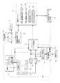
図1は、本発明の実施の形態に係る撮像装置の構成を示すブロック図である。図2は、図1の撮像装置において、撮像モード時に実現される機能を示すブロック図である。図3は、図1の撮像装置において、再生モード時に実現される機能を示すブロック図である。 FIG. 1 is a block diagram showing a configuration of an imaging apparatus according to an embodiment of the present invention. FIG. 2 is a block diagram illustrating functions realized in the imaging mode in the imaging apparatus of FIG. FIG. 3 is a block diagram illustrating functions realized in the reproduction mode in the imaging apparatus of FIG.
撮像装置は、たとえば、カメラ付き携帯電話機、ビデオカメラなどといった携帯可能な撮像装置である。撮像装置は、カメラユニット部1と、操作部2と、コントローラ部3と、を有する。撮像装置は、撮像モードにおいて、静止画を撮像し、再生モードにおいて、撮像した静止画を表示する。
The imaging device is a portable imaging device such as a camera-equipped mobile phone or a video camera. The imaging device includes a
カメラユニット部1は、撮像デバイス11と、撮像手段としての撮像コントローラ12と、動き検出手段の一部としての2つのジャイロセンサ13,14と、動き検出手段の一部としての2つのA/D(Analog to Digital)変換器15,16と、を有する。カメラユニット部1は、撮像装置の図示外の筐体内に固定される。
The
撮像デバイス11は、CCD(Charge−Coupled Device)、CMOS(Complementary Metal−Oxide Semiconductor)となどといった受光デバイスであり、複数の受光素子を有する。
The
複数の受光素子は、撮像デバイス11の光軸Xに対して垂直な面上に二次元的に配列される。図1では、この複数の受光素子の二次元的な配列方向を、Y軸およびZ軸として示す。撮像デバイス11には、X軸方向において図示外の光学系ユニットが重ねて配設される。光学系ユニットは、レンズなどで構成され、入射する光による被写体の像を、撮像デバイス11に投影する。
The plurality of light receiving elements are two-dimensionally arranged on a plane perpendicular to the optical axis X of the
各受光素子は、受光光量に応じたレベル信号を出力する。受光素子が出力するレベル信号は、リセット信号が入力されると、初期状態のレベルとなる。受光素子が出力するレベル信号は、リセット信号が入力された後に受光する光量の増加に応じて変化する。 Each light receiving element outputs a level signal corresponding to the amount of received light. When the reset signal is input, the level signal output from the light receiving element becomes the initial level. The level signal output from the light receiving element changes according to the increase in the amount of light received after the reset signal is input.
撮像デバイス11には、撮像コントローラ12が接続される。撮像コントローラ12は、VSYNC(Vertical Synchronizing signal:垂直同期信号)信号発生器17を有し、撮像デバイス11を制御する。VSYNC信号発生器17は、所定の周期毎に、たとえば30分の1秒毎にVSYNC信号を出力する。
An
撮像コントローラ12は、このVSYNC信号を基準タイミングとして、撮像デバイス11に静止画を撮像させる。撮像コントローラ12は、撮像デバイス11からの受光素子毎のレベル信号に基づいて、1フレームの画像を構成するフレーム画像データを生成する。
The
具体的にはたとえば、撮像コントローラ12は、VSYNC信号を検出すると、複数の受光素子をその二次元的な配列に基づく所定のライン数毎に1つのグループとし、その複数のグループに対して時間をずらして順番にリセット信号を出力する。リセット信号を出力してから所定の露光時間の後に、撮像コントローラ12は、そのリセット信号を出力したグループの複数の受光素子のレベル信号を読み取る。撮像コントローラ12は、読み取ったすべての受光素子のレベル信号に基づいて、フレーム画像データを生成する。
Specifically, for example, when the
撮像コントローラ12が生成するフレーム画像データは、たとえば受光素子と同数のピクセル数を有する。複数のピクセルは、複数の受光素子と同様に二次元的に配列される。また、各ピクセルは、たとえばR(Red),G(Green),B(Blue)の3色の色データなどの情報を有する。なお、各ピクセルの色データは、YCCデータであってもよい。
The frame image data generated by the
カメラユニット部1に設けられる2つのジャイロセンサ13,14は、たとえば所定の一方向での角速度を検出し、検出した角速度の大きさに応じたレベル信号を出力するものであればよい。このようなジャイロセンサとしては、「XV−3500CB」などがある。一例としてのこの振動ジャイロセンサ「XV−3500CB」の外形寸法は、5.0[mm]×3.2[mm]×1.3[mm]であり、その質量は66[mg]である。このような小型・薄型の振動ジャイロセンサを使用することで、筐体内の空間が狭い撮像装置でも充分に、ジャイロセンサを設置することが可能となる。
The two
2つのジャイロセンサ13,14の中の一方のジャイロセンサ13は、図1のY軸周りの周回方向の動きによる角速度を検出する。他方のジャイロセンサ14は、図1のZ軸周りの周回方向の動きによる角速度を検出する。したがって、2つのジャイロセンサ13,14は、撮像デバイス11のY軸方向の動きとZ軸方向の動きとを検出する。
One
2つのA/D変換器15,16の中の一方のA/D変換器15は、一方のジャイロセンサ13に接続される。他方のA/D変換器16は、他方のジャイロセンサ14に接続される。これらのA/D変換器15,16は、ジャイロセンサ13,14から出力されるレベル信号をサンプリングするものであればよい。A/D変換器15,16は、VSYNC信号のたとえば32分の1の周期にて、レベル信号をサンプリングすればよい。また、A/D変換器15,16は、レベル信号をサンプリングすることにより得るサンプリング値を、ジャイロデータとして出力する。なお、A/D変換器15,16のサンプリング周期は、コントローラ部3により適宜設定可能としてもよい。
One A /
操作部2は、たとえば撮像ボタン21、再生ボタン22などを有する。操作部2は、ユーザのボタン操作に基づいて入力データを出力する。操作部2は、たとえば、撮像ボタン21が操作されると、撮像モードの開始を指示する入力データを出力する。操作部2は、たとえば、再生ボタン22が操作されると、再生モードの開始を指示する入力データを出力する。
The
コントローラ部3は、中央処理装置(CPU:Central Processing Unit)31と、RAM(Random Access Memory)32と、記憶手段としての記憶デバイス33と、入出力ポート34と、LCD(Liquid Crystal Display:液晶モニタ37)コントローラ35と、これらが接続されるシステムバス36と、を有する。
The
入出力ポート34には、カメラユニット部1の撮像コントローラ12および2つのA/D変換器15,16と、操作部2と、が接続される。撮像コントローラ12は、入出力ポート34へフレーム画像データを出力する。2つのA/D変換器15,16は、入出力ポート34へジャイロデータを出力する。操作部2は、入出力ポート34へ、操作キーに応じた入力データを出力する。
The input /
LCDコントローラ35には、液晶モニタ37と、VRAM(Video Random Access Memory)38と、が接続される。LCDコントローラ35は、システムバス36からフレーム画像データが供給されると、そのフレーム画像データをVRAM38に記憶させる。LCDコントローラ35は、VRAM38からフレーム画像データを所定の周期で読込み、読み込んだデータに基づく画像を液晶モニタ37に表示させる。LCDコントローラ35は、フレーム画像データの読出し要求があった場合、VRAM38からフレーム画像データを読込み、システムバス36へ供給する。
A liquid crystal monitor 37 and a VRAM (Video Random Access Memory) 38 are connected to the
なお、LCDコントローラ35は、これらの処理を適宜実行する。たとえば、システムバス36からのフレーム画像データの書き込み処理と、表示処理とのタイミングが重なった場合、LCDコントローラ35は、たとえばこれらの処理を、処理発生順にて処理する。LCDコントローラ35により、VRAM38へのアクセスは、排他的に管理される。
The
記憶デバイス33は、静止画撮像表示プログラム41、撮像静止画データとしての第一撮像静止画データ42、撮像静止画データとしての第二撮像静止画データ43、補正静止画データ44、ジャイロログデータ45などを記憶する。記憶デバイス33は、たとえばフラッシュメモリなどの各種の半導体メモリや、HDD(Hard Disk Drive)などで構成することができる。
The
中央処理装置31は、記憶デバイス33に記憶される静止画撮像表示プログラム41を読み込んで実行する。これにより、コントローラ部3には、図2中の撮像静止画データ保存部51と、手ブレ検出部52と、ジャイロログデータ保存部53と、補正静止画データ生成手段としての補正静止画データ生成部54と、適正露出時間生成手段およびシーケンス制御手段としての静止画撮像シーケンス制御部55と、図3中の表示処理部61と、が実現される。
The
なお、静止画撮像表示プログラム41は、撮像装置の出荷前に記憶デバイス33に記憶されても、撮像装置の出荷後に記憶デバイス33に記憶されてもよい。撮像装置の出荷後に記憶デバイス33に静止画撮像表示プログラム41を記憶する場合、この静止画撮像表示プログラム41は、たとえばCD−ROM(Compact Disc Read Only Memory)などの記録媒体に記憶されているものをインストールしたり、インターネット、電話回線などの通信媒体を介してサーバなどからダウンロードしたものをインストールしたりすることで、記憶デバイス33に記憶されればよい。
The still image
図2中の撮像静止画データ保存部51は、LCDコントローラ35からフレーム画像データを取得し、記憶デバイス33に記憶させる。撮像静止画データ保存部51は、取得したフレーム画像データを、記憶デバイス33に、第一撮像静止画データ42あるいは第二撮像静止画データ43として記憶させる。
A captured still image
なお、第一撮像静止画データ42は、後述する第一の露出時間の下で撮像コントローラ12により生成されるフレーム画像データである。第二撮像静止画データ43は、第一の露出時間とは異なる、後述する第二の露出時間の下で撮像コントローラ12により生成されるフレーム画像データである。
The first captured still
手ブレ検出部52は、露出期間内に、手ブレが発生しているか否かを判断する。露出期間内に所定の許容手ブレ量(たとえば5ピクセル幅)以上の手ブレが発生している場合、手ブレ検出部52は、手ブレ有りと判断する。露出期間内に所定の許容手ブレ量より小さい手ブレしか発生していない場合、手ブレ検出部52は、手ブレ無しと判断する。
The camera
ジャイロログデータ保存部53は、入出力ポート34に入力されるデータを記憶デバイス33に記憶させる。これにより、記憶デバイス33にジャイロログデータ45が記憶される。
The gyro log
図4は、図1中の記憶デバイス33に保存されるジャイロログデータ45のデータ構造の一例を示す説明図である。図4において、各行は、1つのレコードに相当する。各レコードは、サンプル番号71と、Y軸のジャイロデータ72と、Z軸のジャイロデータ73と、VSYNCマークデータ74と、手ブレマークデータ75と、で構成される。ジャイロログデータ保存部53は、入出力ポート34に新たなジャイロデータが入力されると、1レコード分のデータを記憶デバイス33に記憶させる。
FIG. 4 is an explanatory diagram showing an example of the data structure of the
サンプル番号71は、各レコードに固有の番号である。図4において、サンプル番号71は、上から下に向かって1ずつ増加する番号となっている。ジャイロログデータ保存部53は、生成したレコードを、ジャイロログデータ45の最後尾に(図4で言えば表の一番下に)追加する。したがって、ジャイロログデータ45において、複数のレコードは、ジャイロログデータ保存部53により取得された順番にて、図4の上から下に向かって並んでいる。
The
Y軸のジャイロデータ72は、一方のA/D変換器15が入出力ポート34へ入力するジャイロデータである。Z軸のジャイロデータ73は、他方のA/D変換器16が入出力ポート34へ入力するジャイロデータである。
Y-
VSYNCマークデータ74は、VSYNC信号の有無に応じた値を有するデータである。VSYNCマークデータ74は、ジャイロログデータ保存部53がジャイロデータを取得する時にVSYNC信号がある場合、たとえば「1」となり、VSYNC信号が無い場合、たとえば「0」となる。
The
手ブレマークデータ75は、手ブレ検出部52の判断結果に応じた値を有するデータである。ジャイロログデータ保存部53がジャイロデータを取得する時に手ブレ検出部52が手ブレ無しと判断した結果を出力している場合、手ブレマークデータ75は、たとえば「OK」となる。また、ジャイロログデータ保存部53がジャイロデータを取得する時に手ブレ検出部52が手ブレ有りと判断した結果を出力している場合、「NG」となる。
The camera
説明を図2に戻す。補正静止画データ生成部54は、記憶デバイス33に記憶される第一撮像静止画データ42と、第二撮像静止画データ43とに基づいて、所定の演算処理により、新たなフレーム画像データを生成する。補正静止画データ生成部54は、生成したフレーム画像データを補正静止画データ44として、記憶デバイス33に記憶させる。
Returning to FIG. The corrected still image
静止画撮像シーケンス制御部55は、撮像モード時における撮像装置の動作を管理する。静止画撮像シーケンス制御部55は、撮像モード時に、たとえば、撮像コントローラ12、手ブレ検出部52、ジャイロログデータ保存部53、撮像静止画データ保存部51、補正静止画データ生成部54の動作を管理する。
The still image capturing
図3中の表示処理部61は、再生モード時に、記憶デバイス33に記憶される補正静止画データ44を読み込む。表示処理部61は、読み込んだ補正静止画データ44をフレーム画像データとしてLCDコントローラ35へ供給する。
The
次に、以上の構成を有する撮像装置の動作を説明する。以下の説明では、まず、撮像モードについて説明し、次に再生モードについて説明する。 Next, the operation of the imaging apparatus having the above configuration will be described. In the following description, first, the imaging mode will be described, and then the reproduction mode will be described.
撮像装置が起動されると、撮像コントローラ12のVSYNC信号発生器17は、VSYNC信号を所定の周期で出力する。撮像コントローラ12は、このVSYNC信号に同期して、撮像デバイス11に静止画を撮像させ、1フレームの画像を構成するフレーム画像データを生成する。撮像コントローラ12は、生成したフレーム画像データを、入出力ポート34を介して、LCDコントローラ35へ供給する。
When the imaging apparatus is activated, the
フレーム画像データが供給されると、LCDコントローラ35は、そのフレーム画像データをVRAM38に記憶させる。LCDコントローラ35は、VRAM38からフレーム画像データを所定の周期で読込み、読み込んだデータに基づく画像を液晶モニタ37に表示させる。これにより、液晶モニタ37には、撮像デバイス11により撮像された画像が表示される。液晶モニタ37に表示される画像は、VSYNC信号の周期に同期して更新される。
When the frame image data is supplied, the
また、撮像装置が起動されると、中央処理装置31は、記憶デバイス33からRAM32へ静止画撮像表示プログラム41を読み込んで、実行する。これにより、撮像装置には、図2に示す撮像静止画データ保存部51と、手ブレ検出部52と、ジャイロログデータ保存部53と、補正静止画データ生成部54と、静止画撮像シーケンス制御部55と、が実現され、さらに、図3に示す表示処理部61が実現される。
When the imaging apparatus is activated, the
ユーザが撮像ボタン21を操作すると、図2に示すように、操作部2は、撮像モードの開始を指示する入力データを静止画撮像シーケンス制御部55へ供給する。
When the user operates the
図5は、図2中の静止画撮像シーケンス制御部55が実行する静止画撮像シーケンスを示すフローチャートである。
FIG. 5 is a flowchart showing a still image capturing sequence executed by the still image capturing
静止画撮像シーケンス制御部55は、まず、静止画を撮像する適正露出時間を生成する(ステップST1)。具体的にはたとえば、静止画撮像シーケンス制御部55は、LCDコントローラ35へフレーム画像データの読出しを要求する。LCDコントローラ35は、VRAM38からフレーム画像データを読み出して、静止画撮像シーケンス制御部55へ供給する。静止画撮像シーケンス制御部55は、供給されたフレーム画像データによる画像の明るさを解析し、その明るさに応じた適正露出時間を生成する。適正露出時間は、フレーム画像データによる画像が明るいほど、短くなる傾向にある。なお、静止画撮像シーケンス制御部55は、図示外の照度計やCdSセルなどの受光素子により測定される明るさに基づいて、適正露出時間を生成してもよい。
The still image capturing
適正露出時間を生成した後、静止画撮像シーケンス制御部55は、ジャイロログデータ保存部53へジャイロデータの保存開始を指示する(ステップST2)。ジャイロログデータ保存部53は、保存処理を開始し、2つのA/D変換器15,16から入出力ポート34に新たな2つのジャイロデータが入力されると、VSYNC信号発生器17の出力および手ブレ検出部52の出力を入出力ポート34から取得する。ジャイロログデータ保存部53は、取得したそれらのデータおよび新たに生成したサンプル番号71を有するレコードを生成し、そのレコードを記憶デバイス33に追加記憶させる。
After generating the appropriate exposure time, the still image capturing
これにより、入出力ポート34に入力される2つのジャイロデータは、VSYNC信号の有無を示すVSYNCマークデータ74および手ブレの有無を示す手ブレマークデータ75とともに、記憶デバイス33に蓄積される。記憶デバイス33には、ジャイロログデータ45が保存される。
As a result, the two gyro data input to the input /
ジャイロデータの保存開始を指示した後、静止画撮像シーケンス制御部55は、撮像コントローラ12および手ブレ検出部52へ、第一静止画の撮像を指示する。静止画撮像シーケンス制御部55は、適正露出時間の四分の一の時間を露出時間に指定し、第一静止画の撮像を指示する。以下、この第一静止画の露出時間を第一露出時間とよぶ。また、静止画撮像シーケンス制御部55は、撮像静止画データ保存部51に、撮像された第一静止画の保存を指示する(ステップST3)。
After instructing to start storing the gyro data, the still image capturing
第一静止画の撮像が指示されると、撮像コントローラ12は、指定された第一露出時間にて静止画を撮像する。撮像コントローラ12は、受光素子の各グループに対して、リセット信号を出力した後、指定された第一露出時間が経過したら、そのグループの複数の受光素子のレベル信号を読み取る。撮像コントローラ12は、読み取ったすべての受光素子のレベル信号に基づいて、フレーム画像データを生成し、入出力ポート34を介して、LCDコントローラ35へ供給する。LCDコントローラ35は、供給されたフレーム画像データをVRAM38へ保存する。
When imaging of the first still image is instructed, the
第一静止画の保存が指示された撮像静止画データ保存部51は、LCDコントローラ35にフレーム画像データを要求する。LCDコントローラ35は、VRAM38に保存されているフレーム画像データを読み込んで、撮像静止画データ保存部51へ供給する。撮像静止画データ保存部51は、供給されたフレーム画像データを、第一撮像静止画データ42として記憶デバイス33に保存する。
The captured still image
また、撮像コントローラ12とともに第一静止画の撮像が指示された手ブレ検出部52は、第一露出期間内に所定の許容手ブレ量以上の手ブレが発生しているか否かを検出する。具体的には、手ブレ検出部52は、第一静止画の撮像が指示された後、VSYNC信号の入力から第一露出期間に相当する期間について、2つのA/D変換器15,16の出力を監視する。そして、その監視期間中に、たとえば5ピクセル以上などの所定の許容手ブレ量以上の手ブレが発生している場合、手ブレ検出部52は、手ブレ有りと判断する。露出期間内に所定の許容手ブレ量より小さい手ブレしか発生していない場合、手ブレ検出部52は、手ブレ無しと判断する。
In addition, the camera
手ブレ検出部52は、手ブレの判断結果を、静止画撮像シーケンス制御部55およびジャイロログデータ保存部53へ供給する。ジャイロログデータ保存部53は、この手ブレ検出部52の検出結果を、ジャイロデータとともにジャイロログデータ45として保存する。図2に示すように、静止画撮像期間におけるレコードと、次の静止画撮像期間におけるレコードとの間には、「NG」あるいは「OK」となる手ブレマークデータ75が必ず1つ含まれる。
The camera
撮像コントローラ12、手ブレ検出部52および撮像静止画データ保存部51へ指示をしてから第一露出期間が経過すると、静止画撮像シーケンス制御部55は、第一静止画に手ブレが発生しているか否かを判断する(ステップST4)。静止画撮像シーケンス制御部55は、手ブレ検出部52の検出結果に基づいて、手ブレが発生しているか否かを判断する。
When the first exposure period elapses after instructing the
手ブレ検出部52が手ブレを検出している場合、静止画撮像シーケンス制御部55は、記憶デバイス33に記憶されている第一撮像静止画データ42を削除し(ステップST5)、再び第一露出時間により、撮像コントローラ12、手ブレ検出部52および撮像静止画データ保存部51に第一静止画の撮像および保存を指示する(ステップST3)。
When the camera
その結果、撮像コントローラ12は、第一露出時間にて静止画を撮像し、撮像静止画データ保存部51は、その静止画のフレーム画像データを第一撮像静止画データ42として記憶デバイス33に保存する。手ブレ検出部52は、第一露出期間における手ブレの有無を検出し、ジャイロログデータ保存部53は、その手ブレ検出部52の検出結果を含むレコードを、ジャイロログデータ45として記憶デバイス33に保存する。これにより、記憶デバイス33には、新たに撮像された第一撮像静止画データ42と、その撮像期間までのジャイロログデータ45が保存される。
As a result, the
また、静止画撮像シーケンス制御部55は、第一露出時間経過後に再び、手ブレ検出部52の検出結果に基づいて、手ブレが発生しているか否かを判断する(ステップST4)。
The still image capturing
手ブレ検出部52が手ブレを検出していない場合、静止画撮像シーケンス制御部55は、第二静止画の撮像処理を開始する。具体的には、静止画撮像シーケンス制御部55は、適正露出時間の二分の一の時間を第二露出時間として指定し、撮像コントローラ12、手ブレ検出部52および撮像静止画データ保存部51に、第二静止画の撮像および保存を指示する(ステップST6)。
When the camera
第二静止画の撮像が指示されると、撮像コントローラ12は、指定された第二露出時間にて静止画を撮像する。撮像静止画データ保存部51は、その静止画のフレーム画像データを第二撮像静止画データ43として記憶デバイス33に保存する。手ブレ検出部52は、第二露出期間における手ブレの有無を検出する。ジャイロログデータ保存部53は、その手ブレ検出部52の検出結果を含むレコードを、ジャイロログデータ45として記憶デバイス33に保存する。
When imaging of the second still image is instructed, the
撮像コントローラ12、手ブレ検出部52および撮像静止画データ保存部51へ指示をしてから第二露出期間が経過すると、静止画撮像シーケンス制御部55は、第二静止画に手ブレが発生しているか否かを判断する(ステップST7)。静止画撮像シーケンス制御部55は、手ブレ検出部52の第二露出期間における検出結果に基づいて、手ブレが発生しているか否かを判断する。
When the second exposure period elapses after instructing the
手ブレ検出部52が手ブレを検出している場合、静止画撮像シーケンス制御部55は、記憶デバイス33に記憶されている第二撮像静止画データ43を削除し(ステップST8)、再び第二露出時間により、撮像コントローラ12、手ブレ検出部52および撮像静止画データ保存部51に第二静止画の撮像および保存を指示する(ステップST6)。
When the camera
撮像コントローラ12は、第二露出時間にて静止画を撮像し、撮像静止画データ保存部51は、その静止画のフレーム画像データを第二撮像静止画データ43として記憶デバイス33に保存する。手ブレ検出部52は、第二露出期間における手ブレの有無を検出し、ジャイロログデータ保存部53は、その手ブレ検出部52の検出結果を含むレコードを、ジャイロログデータ45として記憶デバイス33に保存する。これにより、記憶デバイス33には、新たに撮像された第二撮像静止画データ43と、その撮像期間におけるジャイロログデータ45が保存される。
The
また、静止画撮像シーケンス制御部55は、第二露出時間経過後に再び、手ブレ検出部52の検出結果に基づいて、手ブレが発生しているか否かを判断する(ステップST7)。
Further, the still image capturing
手ブレ検出部52が手ブレを検出していない場合、静止画撮像シーケンス制御部55は、ジャイロログデータ保存部53へジャイロデータの保存終了を指示する(ステップST9)。ジャイロログデータ保存部53は、保存処理を終了する。これにより、記憶デバイス33には、静止画撮像シーケンス制御部55がジャイロログデータ保存部53へジャイロデータの保存開始を指示してから、保存終了を指示するまでの期間に相当するジャイロログデータ45が保存される。
When the camera
静止画撮像シーケンス制御部55は、ジャイロログデータ保存部53へジャイロデータの保存終了を指示することで、撮像デバイス11による静止画の撮像処理を終了する。静止画撮像シーケンス制御部55は、補正静止画データ生成部54に、補正静止画の生成を指示する(ステップST10)。
The still image capturing
補正静止画データ生成部54は、補正静止画の生成を開始すると、まず、第一撮像静止画データ42の静止画と、第二撮像静止画データ43の静止画とのずれ量を演算する。
When the corrected still image
図6は、図2中の記憶デバイス33に記憶されるジャイロログデータ45の積分値の時間変化の一例を示す図である。ジャイロログデータ45の複数のレコードは、図4に示すように、時系列に並んでいる。各レコードには、Y軸のジャイロデータ72と、Z軸のジャイロデータ73とが含まれる。図6の縦軸は、たとえばZ軸のジャイロデータ73を、その時系列順にて積分した値である。図6の横軸は、ジャイロデータの保存を開始してからの経過時間である。図6に示すように、ジャイロデータの積分値は、その保存期間において変動する。
FIG. 6 is a diagram illustrating an example of a change over time in the integral value of the
補正静止画データ生成部54は、ジャイロログデータ45の複数のレコードの中から、手ブレマークデータ75が「OK(=手ブレ無し)」となっている2つのレコードを特定する。図4で言えば、サンプル番号「386」のレコードと、サンプル番号「426」のレコードと、が特定される。
The corrected still image
次に、補正静止画データ生成部54は、特定した手ブレ無しの各レコードの前にある、VSYNCマークデータ74が「1(=VSYNC信号有り)」となっているレコードを特定する。図4で言えば、サンプル番号「371」のレコードと、サンプル番号「411」のレコードと、が特定される。これらのレコードは、手ブレ無しと判断された静止画の撮像を開始したタイミングのレコードである。別な言い方をすれば、撮像コントローラ12が撮像し直していない静止画を撮像したときのVSYNC信号のタイミングのレコードである。以下、特定したVSYNC信号有りの2つのレコードの中の時系列順において前側(図4で言えば、サンプル番号「371」のレコード)を、第一レコードとよび、後側(図4で言えば、サンプル番号「411」のレコード)を、第二レコードと呼ぶ。
Next, the corrected still image
次に、補正静止画データ生成部54は、第一レコードから、第二レコードの1つ前のレコードまでのジャイロデータを積分し、その区間のずれ量を計算する。図4では、サンプル番号「371」のレコードのジャイロデータから、サンプル番号「410」のレコードのジャイロデータまでが積分される。このずれ量は、第一静止画の撮像を開始してから、第二静止画の撮像を開始するまでの期間におけるずれ量となる。つまり、第一撮像静止画データ42の静止画と、第二撮像静止画データ43の静止画とのずれ量となる。
Next, the corrected still image
なお、補正静止画データ生成部54は、第一レコードの次のレコード(図4で言えばサンプル番号「372」のレコード)から、第二レコード(図4で言えばサンプル番号「411」のレコード)までのジャイロデータを積分し、これを第一撮像静止画データ42の静止画と、第二撮像静止画データ43の静止画とのずれ量としてもよい。
The corrected still image
第一撮像静止画データ42の静止画と、第二撮像静止画データ43の静止画とのずれ量を計算した後、補正静止画データ生成部54は、このずれ量を相殺する補正量にて第一撮像静止画データ42の静止画と、第二撮像静止画データ43の静止画とを重ね、それら複数の静止画の重なり範囲を特定する。
After calculating the shift amount between the still image of the first captured still
図7は、図2中の第一撮像静止画データ42の静止画と、第二撮像静止画データ43の静止画とを、ずれ量を相殺する補正量にて重ね合わせときの静止画の重なりの対応関係を示す図である。図7において、一点鎖線枠は、第一撮像静止画データ42による静止画の輪郭を示す。二点鎖線枠は、第二撮像静止画データ43による静止画の輪郭を示す。実線枠は、第一撮像静止画データ42の静止画と第二撮像静止画データ43の静止画とが重なる画像範囲の輪郭を示す。なお、この実線枠が、補正静止画データ44による静止画の輪郭となる。
FIG. 7 illustrates the overlap of still images when the still image of the first captured still
第二撮像静止画データ43の静止画は、その輪郭が第一撮像静止画データ42の静止画の輪郭を基準として、補正量の分だけずれて状態で重ね合わされる。図7において、第一撮像静止画データ42の静止画の右下側と、第二撮像静止画データ43の静止画の左上側とが重なる。
The still image of the second imaged still
補正量により第一撮像静止画データ42の静止画と第二撮像静止画データ43の静止画との画像の重なり範囲を特定した後、補正静止画データ生成部54は、その画像の重なり範囲における各ピクセルについて、適正露出時間での色データを演算する。
After specifying the overlapping range of the still image of the first captured still
図8は、補正静止画データ生成部54によるピクセル毎の適正露出時間での色データの演算方法の説明図である。図8において、横軸は、適正露出時間を100%とする露出時間比率である。縦軸は、ピクセルの色データである。
FIG. 8 is an explanatory diagram of a method for calculating color data at an appropriate exposure time for each pixel by the corrected still image
第一撮像静止画データ42の静止画は、適正露出時間の四分の一の第一露出時間で撮像されている。第一露出時間は、適正露出時間を100%としたとき、25%の露出時間比率となる。第二撮像静止画データ43の静止画は、適正露出時間の二分の一の第二露出時間で撮像されている。第二露出時間は、適正露出時間の50%の露出時間比率となる。
The still image of the first captured still
図8に示すように、第一撮像静止画データ42の静止画のあるピクセルの色データがR1であり、第二撮像静止画データ43の静止画のあるピクセルの色データがR2である場合、補正静止画データ生成部54は、それらの色データを直線で結ぶ線分を特定し、その線分において露出時間が100%となるときの色データを、下記式1に基づいて、適正露出時間の色データRoとして演算する。
As shown in FIG. 8, when the color data of a pixel with a still image of the first captured still
Ro =3×R2−2×R1 =(R2−R1)×(1−0.25)/(0.5−0.25)+R1 ・・・式1
Ro = 3 * R2-2 * R1 = (R2-R1) * (1-0.25) / (0.5-0.25) +
補正静止画データ生成部54は、画像の重なり範囲内のすべてのピクセルについて、ピクセル毎に、この演算方式により色データを演算する。
The corrected still image
すべてのピクセルの適正露出時間における色データを演算すると、補正静止画データ生成部54は、補正静止画データ44を生成する。補正静止画データ44の静止画は、第一撮像静止画データ42の静止画と第二撮像静止画データ43の静止画との画像の重なり範囲をその画像範囲とし、且つ、その画像内の各ピクセルの色データとして適正露出時間における色データを有するものである。補正静止画データ生成部54は、生成した補正静止画データ44を、記憶デバイス33に保存する。
When the color data at the appropriate exposure time of all pixels is calculated, the corrected still image
次に、再生モードについて説明する。ユーザが再生ボタン22を操作すると、図3に示すように、操作部2は、再生モードの開始を指示する入力データを表示処理部61へ供給する。
Next, the playback mode will be described. When the user operates the
再生モードの開始指示が入力されると、表示処理部61は、記憶デバイス33から、補正静止画データ44を読み込み、LCDコントローラ35へ供給する。LCDコントローラ35は、供給された補正静止画データ44をVRAM38に書き込む。LCDコントローラ35は、また、VRAM38に記憶されているフレーム画像データを所定の周期で読込み、読み込んだデータに基づく画像を液晶モニタ37に表示させる。これにより、液晶モニタ37には、補正静止画データ44の静止画が表示される。図7で言えば、実線枠内の画像が表示される。
When a playback mode start instruction is input, the
以上のように、この実施の形態では、撮像コントローラ12は、適正露出時間より短い第一露出時間で撮像した第一撮像静止画データ42と、適正露出時間より短い第二露出時間で撮像した第二撮像静止画データ43とを出力する。補正静止画データ44生成は、記憶デバイス33に記憶されているこれらの撮像静止画データに基づいて、適正露出時間にて撮像した静止画としての補正静止画データ44を生成する。
As described above, in this embodiment, the
したがって、適正露出時間より短い露出時間で2つ以上の静止画を撮像し、その2つ以上の静止画に基づいて、適正露出時間にて撮像した静止画を得ることができる。撮像コントローラ12が、適正露出時間にて静止画を撮像する場合に比べて、手ブレの影響を受け難くなる。
Therefore, two or more still images can be captured with an exposure time shorter than the appropriate exposure time, and a still image captured with an appropriate exposure time can be obtained based on the two or more still images. Compared to the case where the
この実施の形態では、第一露出時間を、適正露出時間の四分の一の時間とし、第二露出時間を、適正露出時間の二分の一の時間としている。これらの合計露出時間は、適正露出時間の四分の三となる。したがって、手ブレの影響をより受け難くなる。たとえば、適正露出時間を複数の露出期間に分割し、その分割した露出期間により撮像した複数の静止画を重ね合わせて最終的な静止画を得る場合と比べても、手ブレの影響を受け難くなる。また、撮像ボタン21が操作された直後に手ブレが発生し易いため、その直後の第一露出時間を四分の一とし、第二露出時間を二分の一とすることで、手ブレの影響を少なくすることができる。
In this embodiment, the first exposure time is a quarter of the proper exposure time, and the second exposure time is a half of the proper exposure time. These total exposure times are three quarters of the proper exposure time. Therefore, it is less susceptible to camera shake. For example, compared to the case where the appropriate exposure time is divided into a plurality of exposure periods and a plurality of still images captured by the divided exposure periods are superimposed to obtain a final still image, it is less susceptible to camera shake. Become. Moreover, since camera shake is likely to occur immediately after the
この実施の形態では、補正静止画データ生成部54は、第一撮像静止画データ42と第二撮像静止画データ43とを撮像する期間のジャイロデータを用いて、これらの撮像期間において発生したずれ量を相殺するようにこれらの静止画を重ね合わせた静止画の対応関係に基づいて、補正静止画データ44による静止画を生成している。つまり、撮像コントローラ12のずれ量を相殺するように、2つの撮像静止画データの静止画を対応付けている。
In this embodiment, the corrected still image
したがって、2つの静止画を撮像する期間に手ブレが発生し、これらの静止画の撮像範囲がずれていたとしても、2つの静止画において停止して写っている被写体については、それらが重なるように2つ以上の静止画を対応付けることができる。また、2つの静止画において移動して写っている被写体については、その移動によるブレを含めて2つの静止画を対応付けることができる。2つの静止画を、被写体の動きの有無に応じて適切に対応付けることができる。 Therefore, even if camera shake occurs during the period of capturing two still images and the imaging range of these still images deviates, the subjects appearing to stop in the two still images appear to overlap. Two or more still images can be associated with each other. In addition, with respect to a subject that is moved and photographed in two still images, two still images can be associated with each other including a blur caused by the movement. Two still images can be appropriately associated according to the presence or absence of movement of the subject.
なお、画像処理により各静止画中の特徴点を抽出し、その特徴点の対応関係に基づいて複数の静止画を対応付ける場合には、その特徴点が移動する被写体に基づく特徴点であるときには、複数の静止画を上手く対応付けることができない可能性がある。 When extracting feature points in each still image by image processing and associating a plurality of still images based on the correspondence between the feature points, when the feature points are feature points based on the moving subject, There is a possibility that a plurality of still images cannot be associated well.
この実施の形態では、補正静止画データ44の静止画の各ピクセルの色データは、先の静止画の対応関係において互いに重なり合う複数のピクセルの色データから生成される。したがって、補正静止画データ44の静止画の各ピクセルの情報は、それに対応して互いに重なり合うピクセルの情報から生成され、周囲のピクセルの情報の影響を受けなくなる。その結果、たとえば静止した被写体は、その静止したままの輪郭により補正静止画に組み込まれることになる。動く被写体は、その動きによるブレを含んだ輪郭にて補正静止画に組み込まれることになる。補正静止画データの静止画として、適正露出時間で撮像した静止画と遜色ない画質の静止画を得ることができる。
In this embodiment, the color data of each pixel of the still image of the corrected still
この実施の形態では、第一撮像静止画データ42の各ピクセルの色データと、第二撮像静止画データ43の各ピクセルの色データと、補正撮像静止画データの各ピクセルの色データとが互いに線形関係にあるとして、ピクセル毎の情報を生成している。したがって、補正静止画データ生成部54は、簡単な線形演算により、ピクセル毎の情報を生成することができる。
In this embodiment, the color data of each pixel of the first captured still
この実施の形態では、撮像コントローラ12は、静止画の撮像中に手ブレ検出部52により手ブレが検出された場合には、静止画を撮像し直す。したがって、撮像コントローラ12は、手ブレが検出されない良好な画質の静止画を撮像することができる。
In this embodiment, the
この実施の形態では、補正静止画データ生成部54は、記憶デバイス33に蓄積されたジャイロデータを用いて、撮像コントローラ12から出力される2つの撮像静止画データの静止画のずれ量を演算し、そのずれ量を相殺するように重ねた場合の静止画の対応関係に基づいて、適正露出時間にて撮像した静止画としての補正静止画データ44を生成している。したがって、撮像コントローラ12が静止画を撮像し直したとしても、すべての静止画の撮像の後に、補正静止画データ生成部54は、記憶デバイス33に記憶される2つの撮像静止画データの静止画をずれ量を相殺するように対応付けることかできる。
In this embodiment, the corrected still image
この実施の形態では、補正静止画データ生成部54は、ジャイロログデータ45の手ブレマークデータ75が「OK」であるときのVSYNCマークデータ74「1」のタイミングにおいて各撮像静止画データが撮像されたものとして、静止画を対応付けている。したがって、撮像コントローラ12が静止画を撮像し、その結果としてジャイロログデータ45中に、補正静止画の生成に使用する撮像静止画データの数(ここでは2つ)より多いVSYNCマークデータ74「1」が存在している場合であっても、補正静止画データ生成部54は、補正静止画の生成に使用する複数の撮像静止画データ42,43の静止画を、適切に対応付けることかできる。
In this embodiment, the corrected still image
この実施の形態では、静止画撮像シーケンス制御部55は、撮像ボタン21が操作されたら、適正露出時間を生成し、撮像コントローラ12に2つの撮像静止画データを撮像させ、補正静止画データ生成部54に補正静止画データ44を生成させる。したがって、ユーザにより撮像ボタン21が一度操作されることで、撮像コントローラ12に2つの撮像静止画データを撮像させ、それに基づく補正静止画データ44を生成することかできる。ユーザからすれば、一般的なカメラにおいて静止画を撮像する場合と同様に、撮像ボタン21を1度操作することで、静止画を撮像することができる。
In this embodiment, the still image capturing
以上の実施の形態は、本発明の好適な実施の形態の例であるが、本発明は、これに限定されるものではなく、発明の要旨を逸脱しない範囲において、種々の変形、変更が可能である。 The above embodiment is an example of a preferred embodiment of the present invention, but the present invention is not limited to this, and various modifications and changes can be made without departing from the scope of the invention. It is.
上記実施の形態では、静止画撮像シーケンス制御部55は、適正露出時間を判断した後に、ジャイロログデータ45の蓄積および静止画の撮像を開始している。この他にもたとえば、静止画撮像シーケンス制御部55は、ジャイロログデータ45の蓄積および静止画の撮像を開始した後に、たとえば最初に固定露出時間にて静止画を撮像し、その最初の静止画により適正露出時間を生成し、その後に補正静止画の生成に使用する静止画を撮像するようにしてもよい。さらに他にもたとえば、そのジャイロログデータ45の蓄積および静止画の撮像を開始した後に、最初に撮像した静止画により適正露出時間を生成し、この適正露出時間に基づく露出時間で2つ目以降の静止画を撮像するようにしてもよい。
In the above embodiment, the still image capturing
上記実施の形態では、第一露出時間は、適正露出時間の四分の一であり、第二露出時間は、適正露出時間の二分の一である。この他にもたとえば、第一露出時間を適正露出時間の三分の一とし、第二露出時間を適正露出時間の三分の二としてもよい。また、第一露出時間を適正露出時間の五分の一とし、第二露出時間を適正露出時間の五分の四としてもよい。また、第一露出時間と第二露出時間との和の時間は、1であっても、1より小さくてもよい。但し、合計の露出時間が1より小さい場合、適正露出時間にて画像を撮像する場合に比べて、手ブレの影響をより受け難くなる。 In the above embodiment, the first exposure time is a quarter of the proper exposure time, and the second exposure time is a half of the proper exposure time. In addition, for example, the first exposure time may be set to one third of the proper exposure time, and the second exposure time may be set to two thirds of the proper exposure time. Further, the first exposure time may be set to one fifth of the proper exposure time, and the second exposure time may be set to four fifths of the proper exposure time. Further, the sum of the first exposure time and the second exposure time may be 1 or less than 1. However, when the total exposure time is less than 1, it is less susceptible to camera shake than when an image is captured with an appropriate exposure time.
上記実施の形態では、撮像コントローラ12は、静止画撮像シーケンス制御部55により指定された第一露出時間および第二露出時間にて、静止画を撮像している。この他にもたとえば、撮像コントローラ12は、予め設定された所定の固定値の第一露出時間および第二露出時間にて、静止画を撮像するようにしてもよい。
In the above embodiment, the
上記実施の形態では、第一撮像静止画データ42の静止画と、第二撮像静止画データ43の静止画との2つの静止画を撮像し、その2つの静止画に基づいて補正静止画データ44の静止画を生成している。この他にもたとえば、3つ以上の静止画を撮像し、その3つ以上の静止画から、補正静止画を生成するようにしてもよい。
In the above embodiment, two still images of the still image of the first captured still
上記実施の形態では、補正静止画データ生成部54は、第一撮像静止画データ42の静止画と、第二撮像静止画データ43の静止画とが重なる範囲を画像とする補正静止画を生成している。この他にもたとえば、補正静止画データ生成部54は、第一撮像静止画データ42と同じ範囲を画像とする補正静止画を生成しても、第二撮像静止画データ43と同じ範囲を画像とする補正静止画を生成してもよい。この場合において、他方の画像が重ならない範囲のピクセルの色データについては、たとえば、重なる範囲内のピクセルの適正露出時間の色データと、補正の元にする画像の当該ピクセルの色データとの比を演算し、その比率で色データを増減するようにすればよい。
In the above embodiment, the corrected still image
上記実施の形態では、補正静止画データ生成部54は、補正静止画の各ピクセルの色データを、第一撮像静止画データ42における当該ピクセルの色データと、第二撮像静止画データ43における当該ピクセルの色データと、適正露出時間における当該ピクセルの色データとが互いに線形の関係にあるものとして、演算により得ている。この他にもたとえば、補正静止画データ生成部54は、たとえば第一撮像静止画データ42におけるピクセルの色データと、第二撮像静止画データ43におけるピクセルの色データと、適正露出時間におけるピクセルの値との対応関係を示す色データ対応テーブルなどを用いて、補正静止画の各ピクセルの色データを得るようにしてもよい。色データ対応テーブルを使用することで、たとえば上述した3つの色データが非線形の関係にあるものとして、補正静止画の各ピクセルの色データを得ることが可能となる。
In the above embodiment, the corrected still image
上記実施の形態では、撮像静止画データ保存部51は、LCDコントローラ35から、撮像デバイス11により撮像されたフレーム画像データを得ている。この他にもたとえば、撮像静止画データ保存部51は、撮像コントローラ12や撮像デバイス11から直接に、フレーム画像データを得るようにしてもよい。
In the above embodiment, the captured still image
上記実施の形態では、ジャイロログデータ保存部53は、保存開始指示から保存終了指示までの期間のジャイロデータを、記憶デバイス33に蓄積している。この他にもたとえば、ジャイロログデータ保存部53は、手ブレ検出部52がOKと判断した第一撮像静止画の撮像開始タイミングから、手ブレ検出部52がOKと判断した第二撮像静止画の撮像終了タイミングまでのジャイロデータを、記憶デバイス33に蓄積するようにしてもよい。
In the above embodiment, the gyro log
上記実施の形態では、静止画撮像シーケンス制御部55は、手ブレ有りの場合に、記憶デバイス33から撮像静止画データを削除し、再度同一の露出期間で静止画を撮像させている。この他にもたとえば、静止画撮像シーケンス制御部55は、再度静止画を撮像させる場合には、その露出時間を段階的に増減するようにしてもよい。
In the above embodiment, the still image capturing
更に、この他にもたとえば、静止画撮像シーケンス制御部55は、手ブレ有りの場合であっても、その手ブレ有りのままシーケンスを進め、撮像デバイス11による静止画の撮像が完了してから、その手ブレ有りの画像の手ブレ補正処理を実行し、その後に補正静止画の生成を指示するようにしてもよい。
In addition to this, for example, even when there is a camera shake, the still image capturing
なお、このように手ブレ有りの静止画を補正する場合、静止画撮像シーケンス制御部55は、手ブレ補正処理を実行する手ブレ補正処理部にその処理を指示すればよい。手ブレ補正処理部は、たとえば、その手ブレ有りの静止画を、その静止画の撮像期間中のジャイロデータの個数で分割し、その分割した画像部分毎に、ずれ量に応じた強度にて画像のエッジを強調する処理を実行すればよい。
When correcting a still image with camera shake as described above, the still image capturing
上記実施の形態では、撮像デバイス11は、その複数の受光素子が撮像コントローラ12により複数のグループに分けられ、そのグループ毎に順番に複数の受光素子のレベル信号が読み出されている。この他にもたとえば、撮像デバイス11は、機械式に開閉するシャッタ機構を有するものであってもよい。この場合、撮像コントローラ12は、シャッタが閉じている状態で複数の受光素子をまとめてリセットし、シャッタを所定の露出時間だけ開き、その後に、複数の受光素子のレベル信号をまとめて読み込むようにすればよい。
In the above embodiment, in the
本発明は、カメラ付き携帯電話端末などの撮像装置に利用することができる。 The present invention can be used for an imaging apparatus such as a mobile phone terminal with a camera.
12 撮像コントローラ(撮像手段)、13,14 ジャイロセンサ(動き検出手段の一部)、15,16 A/D変換器(動き検出手段の一部)、21 撮像ボタン、33 記憶デバイス(記憶手段)、42 第一撮像静止画データ(撮像静止画データ)、43 第二撮像静止画データ(撮像静止画データ)、44 補正静止画データ、54 補正静止画データ生成部(補正静止画データ生成手段)、55 静止画撮像シーケンス制御部(適正露出時間生成手段、シーケンス制御手段)、72 Y軸のジャイロデータ(動きデータ)、73 Z軸のジャイロデータ(動きデータ)、74 VSYNCマークデータ(基準タイミングを示すデータ)、75 手ブレマークデータ(静止画を撮像し直したか否かを示すデータ)
12 imaging controller (imaging means), 13, 14 gyro sensor (part of motion detection means), 15, 16 A / D converter (part of motion detection means), 21 imaging button, 33 storage device (storage means) 42 First captured still image data (captured still image data) 43 Second captured still image data (captured still image data) 44 Corrected still image
Claims (10)
上記2つ以上の撮像静止画データを記憶する記憶手段と、
上記記憶手段に記憶される上記2つ以上の撮像静止画データに基づいて、上記適正露出時間にて撮像した静止画としての補正静止画データを生成する補正静止画データ生成手段と、
を有することを特徴とする撮像装置。 Imaging means for outputting imaging still image data of two or more still images captured with an exposure time shorter than the appropriate exposure time;
Storage means for storing the two or more captured still image data;
Corrected still image data generating means for generating corrected still image data as a still image captured at the appropriate exposure time based on the two or more captured still image data stored in the storage means;
An imaging device comprising:
前記補正静止画データ生成手段は、前記2つ以上の撮像静止画データの静止画を、上記動き検出手段により検出される動き量を相殺するように重ねた場合に得られる当該2つ以上の静止画の対応関係に基づいて、前記適正露出時間にて撮像した静止画としての補正静止画データを生成すること、
を特徴とする請求項1または2記載の撮像装置。 Motion detection means for detecting the movement of the imaging means;
The corrected still image data generation unit is configured to obtain the two or more still images obtained when the still images of the two or more captured still image data are overlapped so as to cancel the amount of motion detected by the motion detection unit. Generating corrected still image data as a still image captured at the appropriate exposure time based on the correspondence relationship between the images,
The imaging apparatus according to claim 1, wherein:
前記補正静止画データ生成手段は、前記2つ以上の撮像静止画データの静止画において重なり合う複数のピクセルの情報と、補正静止画データの静止画のピクセルの情報とが線形関係にあるとして、ピクセル毎の情報を生成すること、
を特徴とする請求項4記載の撮像装置。 The imaging means images at least one imaged still image data of the two or more imaged still image data to be imaged with an exposure time different from other imaged still image data,
The corrected still image data generating means is configured to assume that the information of a plurality of pixels overlapping in the still image of the two or more captured still image data and the pixel information of the still image of the corrected still image data are in a linear relationship. Generating information for each,
The imaging apparatus according to claim 4.
前記撮像手段は、静止画の撮像中に上記動き検出手段により手ブレが検出された場合には、静止画を撮像し直すこと、
を特徴とする請求項1または2記載の撮像装置。 Motion detection means for detecting the movement of the imaging means;
The imaging means re-captures a still image when a camera shake is detected by the motion detection means during imaging of the still image;
The imaging apparatus according to claim 1, wherein:
前記補正静止画データ生成手段は、前記記憶手段に蓄積された動きデータを用いて、前記撮像手段から出力される前記2つ以上の撮像静止画データの静止画のずれ量を演算し、そのずれ量を相殺するように重ねた場合の対応関係に基づいて、適正露出時間にて撮像した静止画としての補正静止画データを生成すること、
を特徴とする請求項6記載の撮像装置。 The storage means accumulates and stores motion data detected by the motion detection means,
The corrected still image data generation unit calculates a shift amount of a still image of the two or more captured still image data output from the imaging unit using the motion data stored in the storage unit, and the shift Generating corrected still image data as a still image captured at an appropriate exposure time based on the correspondence relationship when overlapping so as to cancel the amount;
The imaging device according to claim 6.
前記補正静止画データ生成手段は、上記撮像手段が静止画を撮像し直していない静止画の基準タイミングにおいて、前記記憶手段に記憶される前記2つ以上の撮像静止画データのそれぞれが撮像されたものとして重ねること、
を特徴とする請求項7記載の撮像装置。 The storage means includes, in the motion data detected by the motion detection means, data indicating a reference timing at which the imaging means captures a still image and data indicating whether the imaging means has recaptured a still image. Accumulate in association,
The corrected still image data generation means captures each of the two or more captured still image data stored in the storage means at a reference timing of a still image in which the imaging means has not recaptured a still image. To stack as a thing,
The imaging apparatus according to claim 7.
撮像ボタンと、
上記撮像ボタンが操作されたら、上記適正露出時間生成手段に適正露出時間を生成させ、前記撮像手段に前記2つ以上の撮像静止画データを撮像させ、前記補正静止画データ生成手段に補正静止画データを生成させるシーケンス制御手段と、
を有することを特徴とする請求項1から8の中のいずれか1項記載の撮像装置。 Appropriate exposure time generating means for generating an appropriate exposure time based on the still image captured by the imaging means;
An imaging button;
When the imaging button is operated, the appropriate exposure time generation unit generates the appropriate exposure time, the imaging unit captures the two or more captured still image data, and the corrected still image data generation unit causes the corrected still image data to be corrected. Sequence control means for generating data;
The imaging apparatus according to claim 1, wherein the imaging apparatus includes:
上記第一の静止画の後に、上記適正露出時間より短い時間で第二の静止画を撮像するステップと、
上記第一の静止画および上記第二の静止画を用いて、上記適正露出時間にて撮像した静止画としての静止画を生成するステップと、
を有することを特徴とする撮像方法。 Capturing the first still image in a time shorter than the appropriate exposure time;
After the first still image, capturing a second still image in a time shorter than the appropriate exposure time;
Using the first still image and the second still image to generate a still image as a still image captured at the appropriate exposure time;
An imaging method characterized by comprising:
Priority Applications (2)
| Application Number | Priority Date | Filing Date | Title |
|---|---|---|---|
| JP2005170460A JP2006345338A (en) | 2005-06-10 | 2005-06-10 | Image pickup device and imaging method |
| US11/448,729 US7627225B2 (en) | 2005-06-10 | 2006-06-08 | Image capturing device and image capturing method |
Applications Claiming Priority (1)
| Application Number | Priority Date | Filing Date | Title |
|---|---|---|---|
| JP2005170460A JP2006345338A (en) | 2005-06-10 | 2005-06-10 | Image pickup device and imaging method |
Publications (2)
| Publication Number | Publication Date |
|---|---|
| JP2006345338A true JP2006345338A (en) | 2006-12-21 |
| JP2006345338A5 JP2006345338A5 (en) | 2008-04-10 |
Family
ID=37524178
Family Applications (1)
| Application Number | Title | Priority Date | Filing Date |
|---|---|---|---|
| JP2005170460A Withdrawn JP2006345338A (en) | 2005-06-10 | 2005-06-10 | Image pickup device and imaging method |
Country Status (2)
| Country | Link |
|---|---|
| US (1) | US7627225B2 (en) |
| JP (1) | JP2006345338A (en) |
Cited By (1)
| Publication number | Priority date | Publication date | Assignee | Title |
|---|---|---|---|---|
| JP2010141657A (en) * | 2008-12-12 | 2010-06-24 | Sanyo Electric Co Ltd | Imaging apparatus and imaging method |
Families Citing this family (15)
| Publication number | Priority date | Publication date | Assignee | Title |
|---|---|---|---|---|
| US8300117B2 (en) * | 2008-03-28 | 2012-10-30 | Fuji Xerox Co., Ltd. | System and method for exposing video-taking heuristics at point of capture |
| US20090303332A1 (en) * | 2008-06-05 | 2009-12-10 | Kim Heuiwook | System and method for obtaining image of maximum clarity |
| US8957944B2 (en) | 2011-05-17 | 2015-02-17 | Apple Inc. | Positional sensor-assisted motion filtering for panoramic photography |
| US8600194B2 (en) | 2011-05-17 | 2013-12-03 | Apple Inc. | Positional sensor-assisted image registration for panoramic photography |
| US9762794B2 (en) | 2011-05-17 | 2017-09-12 | Apple Inc. | Positional sensor-assisted perspective correction for panoramic photography |
| US9088714B2 (en) | 2011-05-17 | 2015-07-21 | Apple Inc. | Intelligent image blending for panoramic photography |
| JP5780418B2 (en) * | 2011-05-30 | 2015-09-16 | ソニー株式会社 | Imaging apparatus and method, image reproducing apparatus and method, program, and recording medium |
| US9247133B2 (en) | 2011-06-01 | 2016-01-26 | Apple Inc. | Image registration using sliding registration windows |
| US8902335B2 (en) | 2012-06-06 | 2014-12-02 | Apple Inc. | Image blending operations |
| US9098922B2 (en) | 2012-06-06 | 2015-08-04 | Apple Inc. | Adaptive image blending operations |
| US10306140B2 (en) | 2012-06-06 | 2019-05-28 | Apple Inc. | Motion adaptive image slice selection |
| US9832378B2 (en) * | 2013-06-06 | 2017-11-28 | Apple Inc. | Exposure mapping and dynamic thresholding for blending of multiple images using floating exposure |
| KR102047703B1 (en) * | 2013-08-09 | 2019-11-22 | 엘지전자 주식회사 | Mobile terminal and controlling method thereof |
| JP6438190B2 (en) * | 2013-10-21 | 2018-12-12 | キヤノン株式会社 | Imaging apparatus, imaging method, and program |
| US9723218B2 (en) * | 2014-12-09 | 2017-08-01 | Xiaomi Inc. | Method and device for shooting a picture |
Family Cites Families (7)
| Publication number | Priority date | Publication date | Assignee | Title |
|---|---|---|---|---|
| JPH1188810A (en) | 1997-09-04 | 1999-03-30 | Hitachi Ltd | Electronic camera |
| US7176962B2 (en) * | 2001-03-01 | 2007-02-13 | Nikon Corporation | Digital camera and digital processing system for correcting motion blur using spatial frequency |
| WO2004017088A2 (en) * | 2002-08-15 | 2004-02-26 | Lc Technologies, Inc. | Motion clutter suppression for image-subtracting cameras |
| JP2005077886A (en) * | 2003-09-02 | 2005-03-24 | Canon Inc | Photographing equipment |
| JP3829843B2 (en) * | 2003-12-08 | 2006-10-04 | ソニー株式会社 | Image processing device |
| US7705908B2 (en) * | 2003-12-16 | 2010-04-27 | Eastman Kodak Company | Imaging method and system for determining camera operating parameter |
| US7382400B2 (en) * | 2004-02-19 | 2008-06-03 | Robert Bosch Gmbh | Image stabilization system and method for a video camera |
-
2005
- 2005-06-10 JP JP2005170460A patent/JP2006345338A/en not_active Withdrawn
-
2006
- 2006-06-08 US US11/448,729 patent/US7627225B2/en active Active
Cited By (1)
| Publication number | Priority date | Publication date | Assignee | Title |
|---|---|---|---|---|
| JP2010141657A (en) * | 2008-12-12 | 2010-06-24 | Sanyo Electric Co Ltd | Imaging apparatus and imaging method |
Also Published As
| Publication number | Publication date |
|---|---|
| US20060280429A1 (en) | 2006-12-14 |
| US7627225B2 (en) | 2009-12-01 |
Similar Documents
| Publication | Publication Date | Title |
|---|---|---|
| JP2006345338A (en) | Image pickup device and imaging method | |
| EP1845709B1 (en) | Image capturing apparatus, control method therefor, image processing apparatus, image processing method, and program | |
| JP4501994B2 (en) | Imaging device | |
| JP2009284394A (en) | Imaging apparatus and imaging method | |
| JP2007300595A (en) | Method of avoiding shaking during still image photographing | |
| JP2006033850A (en) | Handshake correction method and photographing apparatus using imaging device drive control and memory reading control | |
| JP2007281536A (en) | Object shake detector, photographing device, and method of controlling them, control program, and recording medium | |
| US7701621B2 (en) | Image correction system and correcting method | |
| TWI492618B (en) | Image pickup device and computer readable recording medium | |
| JP2009296561A (en) | Imaging apparatus and imaging method | |
| US20100272423A1 (en) | Shake correcting apparatus and imaging apparatus having the same | |
| JP2007336394A (en) | Imaging apparatus and image compositing method | |
| JP2007221711A (en) | Sensor unit, and electronic device | |
| JPWO2006022229A1 (en) | Imaging optical device, captured image processing system, and captured image processing program | |
| JP4834406B2 (en) | Imaging device | |
| JP6631589B2 (en) | Imaging device | |
| JP2008283477A (en) | Image processor, and image processing method | |
| JP6149615B2 (en) | Imaging device | |
| JP2007129491A (en) | Blurring detection system device, imaging apparatus, external recording medium, and its program | |
| JP2011155568A (en) | Image pickup device | |
| JP4853746B2 (en) | Imaging apparatus, image processing apparatus and method, recording medium, and program | |
| JP2011250235A (en) | Imaging apparatus | |
| KR20100099558A (en) | Apparatus and method for processing digital image | |
| JP2007208742A (en) | Imaging apparatus and method for controlling the same | |
| JP2005039339A (en) | Photographing apparatus |
Legal Events
| Date | Code | Title | Description |
|---|---|---|---|
| RD04 | Notification of resignation of power of attorney |
Free format text: JAPANESE INTERMEDIATE CODE: A7424 Effective date: 20070404 |
|
| A521 | Request for written amendment filed |
Free format text: JAPANESE INTERMEDIATE CODE: A523 Effective date: 20080226 |
|
| A621 | Written request for application examination |
Free format text: JAPANESE INTERMEDIATE CODE: A621 Effective date: 20080226 |
|
| A131 | Notification of reasons for refusal |
Free format text: JAPANESE INTERMEDIATE CODE: A131 Effective date: 20091124 |
|
| A761 | Written withdrawal of application |
Free format text: JAPANESE INTERMEDIATE CODE: A761 Effective date: 20100106 |