JP2006335193A - Rolling characteristic estimation device for vehicle, and rolling motion stabilization controller for vehicle using the same - Google Patents
Rolling characteristic estimation device for vehicle, and rolling motion stabilization controller for vehicle using the same Download PDFInfo
- Publication number
- JP2006335193A JP2006335193A JP2005161516A JP2005161516A JP2006335193A JP 2006335193 A JP2006335193 A JP 2006335193A JP 2005161516 A JP2005161516 A JP 2005161516A JP 2005161516 A JP2005161516 A JP 2005161516A JP 2006335193 A JP2006335193 A JP 2006335193A
- Authority
- JP
- Japan
- Prior art keywords
- vehicle
- roll
- rolling motion
- suspension
- control device
- Prior art date
- Legal status (The legal status is an assumption and is not a legal conclusion. Google has not performed a legal analysis and makes no representation as to the accuracy of the status listed.)
- Pending
Links
Images


Landscapes
- Control Of Driving Devices And Active Controlling Of Vehicle (AREA)
- Regulating Braking Force (AREA)
- Vehicle Body Suspensions (AREA)
Abstract
Description
本発明は、車両のロール特性推定装置、及び該装置を用いた車両のローリング運動安定化制御装置に関し、特に、サスペンション制御装置の作動状況に応じてロール増大傾向の現われ易さを表すロール指標を推定し得る車両のロール特性推定装置、及びサスペンション制御装置の制御状態を考慮して制動力及び駆動力の少なくとも一方の制御を行い車両のローリング運動を安定化する車両のローリング運動安定化制御装置に係る。 The present invention relates to a roll characteristic estimation device for a vehicle, and a rolling motion stabilization control device for a vehicle using the device, and in particular, a roll index representing the ease of occurrence of a roll increase tendency according to the operating state of a suspension control device. A rolling motion stabilization control device for a vehicle that can estimate a roll property of a vehicle and a vehicle rolling motion stabilization control device that stabilizes the rolling motion of the vehicle by controlling at least one of braking force and driving force in consideration of the control state of the suspension control device. Related.
車両のローリング運動の安定化制御に関し、特許文献1には、ブレーキシステムによって車両運動制御ブレーキの介在を行う方法として、「車両がその縦軸回りを傾斜する傾向を表す、少なくとも一つの車両運動の動的特性変数として、対応する傾斜防止しきい値が規定されている。特性変数の瞬時値は連続して取得され、傾斜防止しきい値と比較される。特性変数の瞬時値が傾斜防止しきい値を超えたときには直ちに、車両がその縦軸回りを傾斜するのを防止するため、コーナリング時に外側となる車輪が制動される」と記載されている。車両のローリング運動は、車両重心高などの車両諸元やサスペンションの特性に影響を受ける。従って、上記の特許文献1に示されるような装置においては、車両諸元やサスペンション特性に基づいて制御が行われることが望ましい。 Regarding stabilization control of rolling motion of a vehicle, Patent Document 1 describes as a method of intervening vehicle motion control braking by a brake system, “at least one vehicle motion representing a tendency of the vehicle to tilt around its vertical axis. The corresponding anti-tilt threshold is defined as a dynamic characteristic variable, the instantaneous value of the characteristic variable is continuously acquired and compared with the anti-tilt threshold. As soon as the threshold is exceeded, the outer wheels are braked during cornering to prevent the vehicle from tilting about its longitudinal axis. The rolling motion of the vehicle is affected by vehicle specifications such as the height of the center of gravity of the vehicle and the characteristics of the suspension. Therefore, in the apparatus as disclosed in Patent Document 1 described above, it is desirable that control is performed based on vehicle specifications and suspension characteristics.
一方、サスペンション制御に関し、特許文献2乃至4に示されるようなサスペンション特性を走行状態に応じて制御する装置が知られている。即ち、特許文献2には、エアスプリングと補助エアタンクを連通するエア配管の電磁弁を開閉制御し、エアスプリングのばね定数を切り換えるエアサスペンション用エア配管が記載されている。また、特許文献3には、ショックアブソーバの伸縮速度の低速域においてショックアブソーバの減衰力を可変可能としたアクチュエータにより、車両の旋回時における挙動状態に応じて内輪及び外輪におけるショックアブソーバの減衰力を個別に制御する減衰力制御装置が記載されている。そして、特許文献4には、横加速度センサからの信号に基づいて左右輪間に設けられたスタビライザの見掛け上のねじり剛性を変化させるスタビライザの効力制御装置が記載されている。 On the other hand, with respect to suspension control, there are known devices that control suspension characteristics as shown in Patent Documents 2 to 4 in accordance with a running state. That is, Patent Document 2 describes an air suspension air pipe that controls opening and closing of an electromagnetic valve of an air pipe that communicates an air spring and an auxiliary air tank, and switches a spring constant of the air spring. Further, in Patent Document 3, the damping force of the shock absorber in the inner ring and the outer ring is determined according to the behavior state when the vehicle turns by using an actuator that can change the damping force of the shock absorber in a low speed region of the shock absorber expansion and contraction speed. A damping force control device that individually controls is described. Patent Document 4 describes a stabilizer efficacy control device that changes the apparent torsional rigidity of a stabilizer provided between the left and right wheels based on a signal from a lateral acceleration sensor.
更に、特許文献5には、車両の重心高さの推定に関して、ロールを含む自由度を持つ力学モデルの操舵角に対するロールの伝達関数と、ロールレイトセンサを用いて実車より採取されるデータに基づき、AR法(自己回帰法)を用いて求められる操舵角に対するロールの伝達関数との、係数比較を行って重心高さを導出する装置が記載されている。このような車両重心高を求めるための力学モデルにもサスペンション特性(ロール剛性等)がパラメータとして含まれており、車両のローリング運動に関する特性を推定するためにもサスペンション制御装置の作動状況を把握しサスペンション特性を正確に求めることが必要になる。 Further, in Patent Document 5, the estimation of the height of the center of gravity of the vehicle is based on the transfer function of the roll with respect to the steering angle of the dynamic model having the degree of freedom including the roll and the data collected from the actual vehicle using the roll rate sensor. Describes an apparatus for deriving the height of the center of gravity by comparing coefficients with a transfer function of a roll with respect to a steering angle obtained using the AR method (autoregressive method). Suspension characteristics (roll rigidity, etc.) are also included as parameters in the dynamic model for determining the height of the center of gravity of the vehicle. In order to estimate the characteristics related to rolling motion of the vehicle, the operation status of the suspension control device is grasped. It is necessary to accurately determine the suspension characteristics.
先ず、図2を参照して、車両のローリング運動における状態量について説明する。運転者のステアリングホイール操作により各車輪にスリップ角αxx(ここで、添字xxは各車輪を意味し、frは右側前輪、flは左側前輪、rrは右側後輪、rlは左側後輪を示す)が生ずると共に、各車輪に横力SFxxが発生し、車両は旋回運動を行う。このとき、車輪の発生する横力と釣り合うように、慣性力(遠心力)Fyが車両重心に作用する。車両重心位置はローリング運動の回転中心(ロール中心)とは一致せず、車両重心とロール中心との間の距離(以下、ロールアーム長という)Hsが存在するため、ローリングモーメントMx(=Hs・Fy)が発生する。その結果、ローリングモーメントによって車両にローリング運動が惹起し、これが大きくなりすぎると車両のロール増大傾向が現われる。 First, with reference to FIG. 2, the state quantity in the rolling motion of the vehicle will be described. Slip angle αxx on each wheel by the driver's steering wheel operation (here, subscript xx means each wheel, fr is a right front wheel, fl is a left front wheel, rr is a right rear wheel, and rl is a left rear wheel) And a lateral force SFxx is generated on each wheel, and the vehicle performs a turning motion. At this time, an inertial force (centrifugal force) Fy acts on the center of gravity of the vehicle so as to balance the lateral force generated by the wheels. The position of the center of gravity of the vehicle does not coincide with the center of rotation of the rolling motion (roll center), and there is a distance Hs (hereinafter referred to as roll arm length) between the center of gravity of the vehicle and the center of the roll. Fy) occurs. As a result, a rolling motion is caused in the vehicle by the rolling moment, and if this becomes too large, a tendency of increasing the roll of the vehicle appears.
車両のロール増大傾向には、急激なローリング運動が生じて発生する場合(以下、動的ロール増大傾向という)と、比較的緩やかなローリング運動において発生する場合(以下、静的ロール増大傾向という)と、動的ロール増大傾向と静的ロール増大傾向との中間的ロール増大傾向(以下、中間的ロール増大傾向という)とが存在する。 The roll increase tendency of a vehicle occurs when a sudden rolling motion occurs (hereinafter referred to as a dynamic roll increase trend) and when it occurs in a relatively slow rolling motion (hereinafter referred to as a static roll increase trend). And an intermediate roll increase tendency (hereinafter referred to as an intermediate roll increase tendency) between a dynamic roll increase tendency and a static roll increase tendency.
動的ロール増大傾向は、運転者の急激な操舵操作や切り返し操舵などによってローリング運動が急増し、サスペンション部材が縮み側バウンドストッパに衝突し、その衝撃でサスペンション伸び側の車輪が持ち上げられようとすることによって発生する。サスペンション制御装置によって、ばね力や減衰力を高めることは、車両のローリング運動が急激には発生しない特性となる。従って、サスペンション制御装置は、乗り心地や操縦安定性を向上させる一方で、車両のロール姿勢を安定化し、車両のロール増大傾向を抑制する効果も有する。 The dynamic roll increase tendency is that the rolling motion suddenly increases due to the driver's sudden steering operation or turning back steering, the suspension member collides with the contraction side bound stopper, and the wheel on the suspension extension side tends to be lifted by the impact. Caused by that. Increasing the spring force and damping force by the suspension control device has a characteristic that the rolling motion of the vehicle does not occur abruptly. Therefore, the suspension control device has the effect of stabilizing the roll posture of the vehicle and suppressing the tendency of the vehicle to increase the roll while improving the ride comfort and the handling stability.
一方、静的ロール増大傾向は、ロール角速度が小さいにもかかわらず、ロール角が徐々に増大するような緩やかなローリング運動において発生する。これは、乗員の増加や積載条件の変化などによって車両重心位置が高くなっていることが主な原因である。これは、ロールアーム長Hsが大きい場合には、同一の慣性力Fyが作用しても、ローリングモーメントMxは大きくなり、ロール増大傾向が生じやすくなるためである。従って、車両のローリング運動特性に適応してロール増大傾向を判定しローリング運動安定化制御を行うためには、車両の重心高を含むロール増大傾向の現われ易さを表す特性(以下、ロール指標という)を求める必要がある。 On the other hand, the static roll increasing tendency occurs in a gradual rolling motion in which the roll angle gradually increases despite the small roll angular velocity. The main reason for this is that the position of the center of gravity of the vehicle is high due to an increase in occupants and changes in loading conditions. This is because when the roll arm length Hs is large, the rolling moment Mx is large even if the same inertial force Fy is applied, and a tendency to increase the roll tends to occur. Therefore, in order to determine the roll increase tendency in accordance with the rolling motion characteristic of the vehicle and perform the rolling motion stabilization control, a characteristic (hereinafter referred to as a roll index) representing the ease of appearance of the roll increase tendency including the height of the center of gravity of the vehicle. ).
そこで、本発明は、サスペンション特性を調整可能なサスペンション制御装置を具備する車両において、車両のローリング運動におけるロール増大傾向の現われ易さを表す指標を、サスペンション制御装置の作動状況を考慮して、精度よく推定し得る車両のロール特性推定装置を提供することを課題とする。 Therefore, the present invention provides an index representing the ease of appearance of a roll increasing tendency in a rolling motion of a vehicle in a vehicle having a suspension control device capable of adjusting suspension characteristics, taking into account the operation status of the suspension control device. It is an object of the present invention to provide a vehicle roll characteristic estimation apparatus that can be well estimated.
また、本発明は、サスペンション特性を調整可能なサスペンション制御装置を具備する車両において、サスペンション制御装置の作動状況を考慮して、車両のロール増大傾向を抑制し、ローリング運動安定化制御を行う車両のローリング運動安定化制御装置を提供することを別の課題とする。 In addition, the present invention provides a vehicle having a suspension control device capable of adjusting suspension characteristics, which suppresses the tendency of the vehicle to increase in rolls and performs rolling motion stabilization control in consideration of the operation status of the suspension control device. Another object is to provide a rolling motion stabilization control device.
上記の課題を達成するため、本発明は、請求項1に記載のように、サスペンション特性を調整可能なサスペンション制御装置を備えた車両に搭載し、該車両のロール特性を推定する車両のロール特性推定装置において、前記サスペンション特性を取得するサスペンション特性取得手段と、走行中の前記車両の実ローリング運動を検出するローリング運動検出手段と、前記車両の横加速度を検出する横加速度検出手段と、該横加速度検出手段が検出する横加速度及び前記サスペンション特性取得手段が取得するサスペンション特性に基づいて演算し前記車両のローリング運動を推定するローリング運動推定手段と、前記ローリング運動検出手段が検出する実ローリング運動と前記ローリング運動推定手段が演算する推定ローリング運動との比較結果に応じて、前記車両のロール増大傾向の現われ易さを示すロール指標を推定するロール指標推定手段とを備えることとしたものである。 In order to achieve the above object, according to the present invention, a roll characteristic of a vehicle that is mounted on a vehicle including a suspension control device capable of adjusting a suspension characteristic and estimates the roll characteristic of the vehicle is provided. In the estimation apparatus, a suspension characteristic acquisition unit that acquires the suspension characteristic, a rolling motion detection unit that detects an actual rolling motion of the vehicle during traveling, a lateral acceleration detection unit that detects a lateral acceleration of the vehicle, A rolling motion estimating means for estimating a rolling motion of the vehicle by calculating based on a lateral acceleration detected by the acceleration detecting means and a suspension characteristic acquired by the suspension characteristic acquiring means; and an actual rolling motion detected by the rolling motion detecting means; Comparison with the estimated rolling motion calculated by the rolling motion estimation means Depending on the fruit, it is obtained by a further comprising a roll index estimation means for estimating a roll indicator of roll increasing tendency of appearing ease of the vehicle.
そして、請求項2に記載のように、サスペンション特性を調整可能なサスペンション制御装置を備えた車両に搭載し、走行中の当該車両のローリング運動を安定化する車両のローリング運動安定化制御装置において、前記サスペンション特性を取得するサスペンション特性取得手段と、走行中の前記車両の実ローリング運動を検出するローリング運動検出手段と、前記車両の横加速度を検出する横加速度検出手段と、該横加速度検出手段が検出する横加速度及び前記サスペンション特性取得手段が取得するサスペンション特性に基づいて演算し前記車両のローリング運動を推定するローリング運動推定手段と、前記ローリング運動検出手段が検出する実ローリング運動と前記ローリング運動推定手段が演算する推定ローリング運動との比較結果に応じて、前記車両のロール増大傾向の現われ易さを示すロール指標を推定するロール指標推定手段と、該ロール指標推定手段が推定するロール指標に基づき、前記車両のロール増大傾向の判定基準を設定するロール増大傾向判定基準設定手段と、該ロール増大傾向判定基準設定手段が設定するロール増大傾向判定基準に基づき前記車両の制動力制御及び駆動力制御のうち少なくとも一方の制御を行なう制御手段とを備えた構成とするとよい。 And, as described in claim 2, in a rolling motion stabilization control device for a vehicle that is mounted on a vehicle equipped with a suspension control device capable of adjusting suspension characteristics and stabilizes the rolling motion of the vehicle during traveling. Suspension characteristic acquisition means for acquiring the suspension characteristic, rolling motion detection means for detecting the actual rolling motion of the vehicle while traveling, lateral acceleration detection means for detecting lateral acceleration of the vehicle, and the lateral acceleration detection means Rolling motion estimation means for estimating the rolling motion of the vehicle by calculating based on the lateral acceleration to be detected and the suspension characteristics acquired by the suspension characteristic acquisition means, the actual rolling motion and the rolling motion estimation detected by the rolling motion detection means Comparison with estimated rolling motion calculated by means And a roll index estimation means for estimating a roll index indicating the ease of occurrence of the roll increase tendency of the vehicle, and a criterion for determining the roll increase tendency of the vehicle based on the roll index estimated by the roll index estimation means. Roll increasing tendency determination criterion setting means to be set; and control means for performing at least one of braking force control and driving force control of the vehicle based on the roll increasing tendency determination criterion set by the roll increase tendency determination criterion setting means; It is good to have a configuration comprising
あるいは、請求項3に記載のように、サスペンション特性を調整可能なサスペンション制御装置を備えた車両に搭載し、走行中の当該車両のローリング運動を安定化する車両のローリング運動安定化制御装置において、前記サスペンション特性を取得するサスペンション特性取得手段と、走行中の前記車両の実ローリング運動を検出するローリング運動検出手段と、前記車両の横加速度を検出する横加速度検出手段と、該横加速度検出手段が検出する横加速度及び前記サスペンション特性取得手段が取得するサスペンション特性に基づいて演算し前記車両のローリング運動を推定するローリング運動推定手段と、前記ローリング運動検出手段が検出する実ローリング運動と前記ローリング運動推定手段が演算する推定ローリング運動との比較結果に応じて、前記車両のロール増大傾向の判定基準を設定するロール増大傾向判定基準設定手段と、該ロール増大傾向判定基準設定手段が設定するロール増大傾向判定基準に基づき前記車両の制動力制御及び駆動力制御のうち少なくとも一方の制御を行なう制御手段とを備えた構成としてもよい。 Alternatively, as described in claim 3, in a vehicle rolling motion stabilization control device that is mounted on a vehicle equipped with a suspension control device capable of adjusting suspension characteristics and stabilizes the rolling motion of the vehicle during traveling. Suspension characteristic acquisition means for acquiring the suspension characteristic, rolling motion detection means for detecting the actual rolling motion of the vehicle while traveling, lateral acceleration detection means for detecting lateral acceleration of the vehicle, and the lateral acceleration detection means Rolling motion estimation means for estimating the rolling motion of the vehicle by calculating based on the lateral acceleration to be detected and the suspension characteristics acquired by the suspension characteristic acquisition means, the actual rolling motion and the rolling motion estimation detected by the rolling motion detection means Comparison with estimated rolling motion calculated by means According to the result, a roll increase tendency determination criterion setting means for setting a determination criterion for the roll increase tendency of the vehicle, and a braking force control for the vehicle based on the roll increase tendency determination criterion set by the roll increase tendency determination criterion setting means And a control means for controlling at least one of the driving force controls.
更に、請求項4に記載のように、前記サスペンション制御装置の故障を判定する故障判定手段を備えたものとし、前記ロール増大傾向判定基準設定手段が、前記故障判定手段の判定結果に基づき前記車両のロール増大傾向の判定基準を変更して設定するように構成してもよい。 Furthermore, as defined in claim 4, it is assumed that a failure determination means for determining a failure of the suspension control device is provided, and the roll increase tendency determination criterion setting means is configured to determine the vehicle based on the determination result of the failure determination means. You may comprise so that the criteria of determination of the roll increase tendency may be changed and set.
本発明は上述のように構成されているので以下の効果を奏する。即ち、請求項1に記載の車両のロール特性推定装置においては、横加速度検出手段が検出する横加速度及びサスペンション特性取得手段が取得するサスペンション特性に基づいて車両のローリング運動を推定演算し、演算結果の推定ローリング運動と実ローリング運動との比較結果に応じて、ロール指標を推定するように構成されており、ロール指標にサスペンション制御装置の制御状態が反映されるので、ロール指標を精度よく推定することができる。 Since this invention is comprised as mentioned above, there exist the following effects. That is, in the vehicle roll characteristic estimation apparatus according to claim 1, the rolling motion of the vehicle is estimated and calculated based on the lateral acceleration detected by the lateral acceleration detection means and the suspension characteristics acquired by the suspension characteristic acquisition means, and the calculation result The roll index is estimated according to the comparison result between the estimated rolling motion and the actual rolling motion, and the control status of the suspension control device is reflected in the roll index, so the roll index is accurately estimated. be able to.
そして、請求項2及び3に記載の車両のローリング運動安定化制御装置によれば、車両のローリング運動の安定化に影響を及ぼすサスペンション特性に基づいてローリング運動安定化制御を行うことができるため、適切にロール増大傾向を抑制することができると共に、不必要な制御作動も抑制することができる。 According to the rolling motion stabilization control device for a vehicle according to claims 2 and 3, since the rolling motion stabilization control can be performed based on the suspension characteristics that affect the stabilization of the rolling motion of the vehicle, It is possible to appropriately suppress the roll increase tendency and to suppress unnecessary control operations.
更に、請求項4に記載の車両のローリング運動安定化制御装置によれば、ロール増大傾向判定基準設定手段が、故障判定手段の判定結果に基づき車両のロール増大傾向の判定基準を変更して設定するように構成されているので、万一サスペンション制御装置が故障した場合には早期にロール増大傾向を抑制するように制御することができる。 Furthermore, according to the rolling motion stabilization control device for a vehicle according to claim 4, the roll increase tendency determination criterion setting means changes and sets the determination criterion for the roll increase tendency of the vehicle based on the determination result of the failure determination means. Therefore, if the suspension control device breaks down, it can be controlled to suppress the roll increase tendency at an early stage.
以下、本発明の実施形態について図面を参照して説明する。図1は本発明の一実施形態に係る車両のロール特性推定装置、及び車両のローリング運動安定化制御装置の全体構成を示す。図1において、本実施形態の車両は、サスペンション特性を調整可能なサスペンション制御装置SCMを備えており、この車両に搭載されるロール特性推定装置は、サスペンション特性を取得するサスペンション特性取得手段M0を備えている。更に、走行中の車両の実ローリング運動を検出するローリング運動検出手段M1と、車両の横加速度を検出する横加速度検出手段M2と、この横加速度検出手段M2が検出する横加速度及びサスペンション特性取得手段M0が取得するサスペンション特性に基づいて演算し車両のローリング運動を推定するローリング運動推定手段M3と、ローリング運動検出手段M1が検出する実ローリング運動とローリング運動推定手段M3が演算する推定ローリング運動との比較結果に応じて、車両のロール増大傾向の現われ易さを示すロール指標を推定するロール指標推定手段M4を備えたものである。例えば、ロール指標の推定に供する伝達関数のパラメータにサスペンション特性を含め、サスペンション制御装置SCMの制御状態を反映することにより、ロール指標の推定精度が向上する。 Embodiments of the present invention will be described below with reference to the drawings. FIG. 1 shows the overall configuration of a vehicle roll characteristic estimation device and a vehicle rolling motion stabilization control device according to an embodiment of the present invention. In FIG. 1, the vehicle of this embodiment includes a suspension control device SCM capable of adjusting suspension characteristics, and the roll property estimation device mounted on the vehicle includes suspension property acquisition means M0 for acquiring suspension properties. ing. Further, a rolling motion detection means M1 for detecting the actual rolling motion of the running vehicle, a lateral acceleration detection means M2 for detecting the lateral acceleration of the vehicle, and a lateral acceleration and suspension characteristic acquisition means detected by the lateral acceleration detection means M2. The rolling motion estimation means M3 that calculates based on the suspension characteristics acquired by M0 and estimates the rolling motion of the vehicle, the actual rolling motion detected by the rolling motion detection means M1, and the estimated rolling motion calculated by the rolling motion estimation means M3 According to the comparison result, there is provided a roll index estimation means M4 for estimating a roll index indicating the ease of appearance of the roll increase tendency of the vehicle. For example, the estimation accuracy of the roll index is improved by including the suspension characteristic in the parameter of the transfer function used for estimating the roll index and reflecting the control state of the suspension control device SCM.
そして、車両のローリング運動安定化制御装置は、サスペンション制御装置SCMを備えた車両に搭載され、上記のロール特性推定装置を備えると共に、破線で示すように、ロール指標推定手段M4が推定するロール指標に基づき、車両のロール増大傾向の判定基準を設定するロール増大傾向判定基準設定手段M5と、このロール増大傾向判定基準設定手段M5が設定するロール増大傾向判定基準に基づき車両の制動力制御及び駆動力制御のうち少なくとも一方の制御を行なう制御手段M6を備えた構成とすることができる。 The rolling motion stabilization control device for a vehicle is mounted on a vehicle equipped with a suspension control device SCM, includes the roll characteristic estimation device described above, and, as indicated by a broken line, the roll index estimated by the roll index estimation means M4. Based on the roll increase tendency determination criterion setting means M5 for setting a determination criterion for the roll increase tendency of the vehicle, and the braking force control and driving of the vehicle based on the roll increase tendency determination criterion set by the roll increase tendency determination criterion setting means M5. A control means M6 that performs at least one of the force controls can be provided.
また、車両のローリング運動安定化制御装置としては、ロール指標推定手段M4を設けることなく、図1に破線矢印で示すように、ローリング運動検出手段M1が検出する実ローリング運動とローリング運動推定手段M3が演算する推定ローリング運動との比較結果に応じて、ロール増大傾向判定基準設定手段M5において車両のロール増大傾向の判定基準を設定するように構成することとしてもよい。 Further, as a rolling motion stabilization control device for a vehicle, an actual rolling motion and rolling motion estimation means M3 detected by the rolling motion detection means M1, as indicated by a broken line arrow in FIG. 1, without providing the roll index estimation means M4. The roll increase tendency determination criterion setting unit M5 may set the determination criterion for the roll increase tendency of the vehicle in accordance with the comparison result with the estimated rolling motion calculated by.
更に、図1に破線で示すように、サスペンション制御装置SCMの故障を判定する故障判定手段M7を備えたものとし、ロール増大傾向判定基準設定手段M5において、故障判定手段M7の判定結果に基づき車両のロール増大傾向の判定基準を変更して設定するように構成することとしてもよい。即ち、サスペンション制御装置SCMが故障した場合にはロール増大傾向が発生し易くなることも想定できるため、ロール増大傾向判定基準設定手段M5にて、例えば判定基準を小さい特性として、ローリング運動を安定化するための制動力制御及び駆動力制御を、より早期に実行するように設定することができる。 Further, as indicated by a broken line in FIG. 1, it is assumed that failure determination means M7 for determining a failure of the suspension control device SCM is provided, and the roll increase tendency determination criterion setting means M5 is based on the determination result of the failure determination means M7. It may be configured to change and set the criterion for determining the roll increase tendency. That is, it can be assumed that if the suspension control device SCM breaks down, the tendency to increase the roll is likely to occur, so the roll increase tendency determination criterion setting means M5 stabilizes the rolling motion, for example, with a small criterion. Therefore, it is possible to set the braking force control and the driving force control to be performed earlier.
上記のローリング運動検出手段M1及びローリング運動推定手段M3におけるローリング運動は、図3に示すように分類することができ、車両のローリング運動は状態量として表すことができる。図3において、車両のローリング運動を表すロール状態量は、ローリング運動の出力(結果)である出力状態量と、入力(原因)である入力状態量とに分類することができる。ここで、ローリング運動の出力に関する出力状態量としては、ロール角Ra、ロール角速度Rrがある。また、サスペンションの動きに着目すれば、サスペンションストロークSTxx、及びその速度dSTxxがロール出力状態量に該当する。そして、ローリング運動の入力を表す状態量(入力状態量)としては、ステアリングホイールSWの操舵角δsw及び操舵角速度dδsw、車輪スリップ角αxx及びその速度dαxx、車両スリップ角β及びその速度dβ、車輪の横力SFxx及びその時間変化dSFxx、車体慣性力Fy及びその時間変化dFy、更に、ローリング運動の直接の入力であるローリングモーメントMx、及びその時間変化dMxがある。 The rolling motion in the above-described rolling motion detection means M1 and rolling motion estimation means M3 can be classified as shown in FIG. 3, and the rolling motion of the vehicle can be expressed as a state quantity. In FIG. 3, the roll state quantity representing the rolling motion of the vehicle can be classified into an output state quantity that is an output (result) of the rolling motion and an input state quantity that is an input (cause). Here, the output state quantity relating to the output of the rolling motion includes a roll angle Ra and a roll angular velocity Rr. If attention is paid to the movement of the suspension, the suspension stroke STxx and the speed dSTxx correspond to the roll output state quantity. As the state quantity (input state quantity) representing the input of the rolling motion, the steering angle δsw and the steering angular speed dδsw of the steering wheel SW, the wheel slip angle αxx and the speed dαxx, the vehicle slip angle β and the speed dβ, There are a lateral force SFxx and its time change dSFxx, a vehicle body inertia force Fy and its time change dFy, a rolling moment Mx which is a direct input of the rolling motion, and its time change dMx.
また、慣性力(車輪の横力の総和)は車両の横加速度と対応しているため、後述する横加速度センサGYで検出される横加速度(検出横加速度)Gy及びその時間変化dGyも入力状態量ということができる。そして、車輪の横力がヨーイングモーメントを発生させ、その結果、車両はヨーイング運動を行うが、ヨーイングモーメントYm及びその時間変化dYm、ヨー角速度Yr及びその時間変化(ヨー角加速度)dYrもローリング運動の入力状態量とすることができる。 Further, since the inertial force (the sum of the lateral forces of the wheels) corresponds to the lateral acceleration of the vehicle, the lateral acceleration (detected lateral acceleration) Gy detected by a lateral acceleration sensor GY described later and its time change dGy are also input. It can be called quantity. The lateral force of the wheel generates a yawing moment. As a result, the vehicle performs a yawing motion. The yawing moment Ym and its time change dYm, the yaw angular velocity Yr and its time change (yaw angular acceleration) dYr are also affected by the rolling motion. It can be an input state quantity.
ここで、車両の横加速度Gyは、以下の各式で示すように、他の状態量を用いて表現することもできるため、これらを入力状態量とすることもできる。先ず、ヨー角速度Yrから求められる演算横加速度Gy1は以下のように演算される。
Gy1=V・Yr …(1)
ここで、Vは車両速度である。
Here, since the lateral acceleration Gy of the vehicle can also be expressed using other state quantities as shown by the following equations, these can also be used as input state quantities. First, the calculated lateral acceleration Gy1 obtained from the yaw angular velocity Yr is calculated as follows.
Gy1 = V · Yr (1)
Here, V is the vehicle speed.
同様に、演算横加速度Gy1の時間変化dGy1は以下のように演算される。
dGy1=V・dYr …(2)
ここで、dYrはヨー角速度Yrの時間変化(ヨー角加速度)である。
Similarly, the time change dGy1 of the calculated lateral acceleration Gy1 is calculated as follows.
dGy1 = V · dYr (2)
Here, dYr is a time change (yaw angular acceleration) of the yaw angular velocity Yr.
ステアリングホイールSWの操舵角δswから求められる演算横加速度Gy2は以下のように演算される。
Gy2={V2/〔L・(1+Kh・V2)〕}・(δsw/N) …(3)
ここで、Lはホイールベース、Khはスタビリティファクタ、Nはステアリングギアレシオである。
The calculated lateral acceleration Gy2 obtained from the steering angle δsw of the steering wheel SW is calculated as follows.
Gy2 = {V 2 / [L · (1 + Kh · V 2 )]} · (δsw / N) (3)
Here, L is a wheel base, Kh is a stability factor, and N is a steering gear ratio.
また、Kh=0(ニュートラルステア)として、下記(3’)式とすることもできる。
Gy2=(V2/L)・(δsw/N) …(3’)
Further, the following equation (3 ′) can also be obtained by setting Kh = 0 (neutral steer).
Gy2 = (V 2 / L) · (δsw / N) (3 ′)
同様に、演算横加速度Gy2の時間変化dGy2は以下のように演算される。
dGy2={V2/〔L・(1+Kh・V2)〕}・(dδsw/N) …(4)
ここで、dδswはステアリングホイールSWの操舵角速度である。
Similarly, the time change dGy2 of the calculated lateral acceleration Gy2 is calculated as follows.
dGy2 = {V 2 / [L · (1 + Kh · V 2 )]} · (dδsw / N) (4)
Here, dδsw is the steering angular velocity of the steering wheel SW.
また、Kh=0(ニュートラルステア)として、下記(4’)式とすることもできる。
dGy2=(V2/L)・(dδsw/N) …(4’)
In addition, the following equation (4 ′) can also be used as Kh = 0 (neutral steer).
dGy2 = (V 2 / L) · (dδsw / N) (4 ′)
以上のローリング運動を表すロール状態量(Rstで表す)をまとめると、下記の[表1]に示すようになる。ここでは、ローリング運動の大きさ及び速さを表すロール量Rmgとロール速度Rspに分類して示している。更に、ローリング運動の結果(出力)と原因(入力)とに着目すれば、ロール出力状態量(Rstr)とロール入力状態量(Rsti)とに分類することができる。ここで、ロール出力状態量Rstrはロール出力量Rmgr及びロール出力速度Rsprであり、ロール入力状態量Rstiはロール入力量Rmgi及びロール入力速度Rspiである。尚、下記の[表1]において、演算によって求められる状態量を括弧内に矢印で示す。

車両運動には右旋回と左旋回の場合があり、それらは一般的には正負の符号付きの値、例えば左旋回を正として、右旋回を負として取り扱われる。しかし、値の大小関係を説明する際に、正負の符号を考慮して説明すると、大小関係の表現が煩雑となるため、以下の説明においては、特に限定がない場合には絶対値についての大小関係を表すものとする。 There are cases of right turn and left turn in vehicle motion, and these are generally treated as positive and negative signed values, for example, left turn as positive and right turn as negative. However, when explaining the magnitude relationship of values, considering the sign of positive and negative, the representation of the magnitude relationship becomes complicated. Therefore, in the following explanation, the magnitude of the absolute value is not particularly limited. It represents a relationship.
次に、本発明の一実施形態に係る車両のローリング運動安定化制御装置を備えた車両の全体構成を図4に示している。ブレーキ系電子制御ユニットECU1、エンジン系電子制御ユニットECU2、及びインパネ系電子制御ユニットECU3が通信バスを介して接続されており、各システム間で互いのシステム情報を共有することができるように構成されている。更に、ステアリングホイールSWの操舵角(以下、単に操舵角という)δswを検出する操舵角センサSA、車両の前後加速度Gxを検出する前後加速度センサGX、車両の横加速度Gyを検出する横加速度センサGY、車両のヨー角速度Yrを検出するヨー角速度センサYR、及び車両のロール角速度Rrを検出するロール角速度センサRRが通信バスに接続され、各電子制御ユニットにセンサ情報を提供できるように構成されている。 Next, FIG. 4 shows an overall configuration of a vehicle including a rolling motion stabilization control device for a vehicle according to an embodiment of the present invention. The brake system electronic control unit ECU1, the engine system electronic control unit ECU2, and the instrument panel system electronic control unit ECU3 are connected via a communication bus so that each system can share system information. ing. Further, a steering angle sensor SA that detects a steering angle (hereinafter simply referred to as a steering angle) δsw of the steering wheel SW, a longitudinal acceleration sensor GX that detects a longitudinal acceleration Gx of the vehicle, and a lateral acceleration sensor GY that detects a lateral acceleration Gy of the vehicle. The yaw angular velocity sensor YR for detecting the yaw angular velocity Yr of the vehicle and the roll angular velocity sensor RR for detecting the roll angular velocity Rr of the vehicle are connected to the communication bus and configured to provide sensor information to each electronic control unit. .
ブレーキアクチュエータBRKは、運転者によるブレーキペダルBPの操作に応じて各車輪に制動力を発生させると共に、後述する車両ローリング運動の安定化制御が必要なときには、ブレーキ系電子制御ユニットECU1の信号に応じて、各車輪の制動力を独立して制御することができる。運転者のブレーキペダルBPの操作量を検出するために、ブレーキアクチュエータBRKには圧力センサPSが備えられ、その検出圧力Pmcがブレーキ系電子制御ユニットECU1に供給される。尚、ローリング運動安定化のための制動力制御は、運転者がブレーキペダルBPの操作を行っていない場合でも実行される。運転者のアクセルペダル(図示せず)の操作量Apは、エンジン系電子制御ユニットECU2に接続されるアクセルペダルセンサAPにより検出され、前述の通信バスを介してブレーキ系電子制御ユニットECU1に送られる。 The brake actuator BRK generates a braking force on each wheel in accordance with the operation of the brake pedal BP by the driver, and responds to a signal from the brake system electronic control unit ECU1 when the vehicle rolling motion stabilization control described later is required. Thus, the braking force of each wheel can be controlled independently. In order to detect the operation amount of the brake pedal BP of the driver, the brake actuator BRK is provided with a pressure sensor PS, and the detected pressure Pmc is supplied to the brake system electronic control unit ECU1. The braking force control for stabilizing the rolling motion is executed even when the driver is not operating the brake pedal BP. An operation amount Ap of a driver's accelerator pedal (not shown) is detected by an accelerator pedal sensor AP connected to the engine system electronic control unit ECU2, and sent to the brake system electronic control unit ECU1 via the communication bus. .
各車輪WHxxのサスペンションには、ばね定数を切換制御可能なエアサスペンションASxx(例えば、前掲の特許文献2に記載)、減衰力が制御可能な減衰力可変ショックアブソーバSAxx(例えば、前掲の特許文献3に記載)が備えられている。また、前輪及び後輪間には、ロール剛性を制御可能な制御スタビライザFT及びRT(例えば、前掲の特許文献4に記載)が備えられている。これらのサスペンション制御装置は、エアサスペンション系電子制御ユニットECU4、ショックアブソーバ系電子制御ユニットECU5、及びスタビライザ系電子制御ユニットECU6により制御される。これら電子制御ユニットは、通信バスに接続され、センサ信号情報及び電子制御ユニット内の演算処理情報を共有する。尚、車両サスペンションとしては、これら全てのサスペンション制御装置を具備するものである必要はなく、上記サスペンション制御装置のうちの少なくとも一つが備えられる。 The suspension of each wheel WHxx includes an air suspension ASxx (for example, described in Patent Document 2 described above) capable of switching and controlling a spring constant, and a damping force variable shock absorber SAxx (for example, Patent Document 3 described above) capable of controlling a damping force. Is provided). Further, between the front wheels and the rear wheels, control stabilizers FT and RT (for example, described in the above-mentioned Patent Document 4) capable of controlling roll rigidity are provided. These suspension control devices are controlled by an air suspension system electronic control unit ECU4, a shock absorber system electronic control unit ECU5, and a stabilizer system electronic control unit ECU6. These electronic control units are connected to a communication bus and share sensor signal information and calculation processing information in the electronic control unit. The vehicle suspension does not have to include all these suspension control devices, and includes at least one of the suspension control devices.
各車輪WHxxには、車輪速度センサWSxxが配設され、これらがブレーキ系電子制御ユニットECU1に接続されており、各車輪の回転速度、即ち車輪速度に比例するパルス数のパルス信号がブレーキ系電子制御ユニットECU1に入力されるように構成されている。そして、ブレーキ系制御ユニットECU1内において、車輪速度センサWSxxからの車輪速度信号Vwxxに基づいて、車両の前後方向速度(車両速度)Vが演算される。また、エアサスペンション制御用の電子制御ユニットECU4には、車高調節を行うために、各車輪WHxxのサスペンションストロークStxxを検出するストロークセンサSTxxが備えられている。 Each wheel WHxx is provided with a wheel speed sensor WSxx, which is connected to the brake system electronic control unit ECU1, and the rotation speed of each wheel, that is, a pulse signal having a pulse number proportional to the wheel speed is generated by the brake system electronic. It is configured to be input to the control unit ECU1. Then, in the brake system control unit ECU1, a longitudinal speed (vehicle speed) V of the vehicle is calculated based on the wheel speed signal Vwxx from the wheel speed sensor WSxx. Further, the electronic control unit ECU4 for air suspension control is provided with a stroke sensor STxx for detecting the suspension stroke Stxx of each wheel WHxx in order to adjust the vehicle height.
本実施形態のローリング運動安定化制御は、ブレーキ系電子制御ユニットECU1内において実行される。ローリング運動安定化制御が実行されると、車両のロール増大傾向を抑制するため、各車輪に作用する制動力が独立して制御される。更に、車輪に作用する駆動力を制御するために、通信バスを介して、エンジン系電子制御ユニットECU2に指令信号が送られ、スロットル開度、点火遅角、燃料噴射量が状況に応じて制御されてエンジントルクが低減され、車輪の駆動力が制御される。このとき、インパネ系電子制御ユニットECU3には、報知指令が通信バスを介して送られ、運転者に装置の作動状態を知らせるために、視覚的、聴覚的な報知手段(図示せず)が駆動される。 The rolling motion stabilization control of the present embodiment is executed in the brake system electronic control unit ECU1. When the rolling motion stabilization control is executed, the braking force acting on each wheel is independently controlled to suppress the tendency of the vehicle to increase in rolls. Further, in order to control the driving force acting on the wheels, a command signal is sent to the engine system electronic control unit ECU2 via the communication bus, and the throttle opening, ignition retard, and fuel injection amount are controlled according to the situation. Thus, the engine torque is reduced and the driving force of the wheels is controlled. At this time, a notification command is sent to the instrument panel electronic control unit ECU3 via a communication bus, and visual and audible notification means (not shown) are driven to notify the driver of the operating state of the device. Is done.
次に、図5及び図6を参照して、図1に示したサスペンション制御装置SCMの具体的態様の一例と、このサスペンション制御装置SCMによって制御されるサスペンション特性(ロール剛性Kx及びロール減衰Cx)について説明する。図5においては、ばね定数を可変とし得るエアサスペンション制御装置ASxxと減衰力を可変制御可能なショックアブソーバ制御装置SAxxを示している。 Next, referring to FIG. 5 and FIG. 6, an example of a specific aspect of the suspension control device SCM shown in FIG. 1 and suspension characteristics (roll rigidity Kx and roll damping Cx) controlled by the suspension control device SCM. Will be described. FIG. 5 shows an air suspension control device ASxx that can change the spring constant and a shock absorber control device SAxx that can variably control the damping force.
エアサスペンション制御装置ASxxは、主ばねを構成するメインエア室CMxxとサブばねを構成するサブエア室CSxxで構成され、これらメインエア室CMxx及びサブエア室CSxxの間の連通又は非連通状態を制御するバルブVSxxによってエアサスペンションのばね定数を可変としている。そして、バルブVSxxへの通電又は非通電情報に基づいて、エアサスペンション制御装置のばね定数特性(ロール剛性Kx)を演算することができる。また、エアサスペンション系電子制御ユニットECU4内で演算処理される目標ばね定数特性に基づいて、エアサスペンション制御装置のばね定数特性(ロール剛性Kx)を演算することもできる。 The air suspension control device ASxx includes a main air chamber CMxx that constitutes a main spring and a sub air chamber CSxx that constitutes a sub spring, and a valve that controls communication or non-communication between the main air chamber CMxx and the sub air chamber CSxx. The spring constant of the air suspension is made variable by VSxx. The spring constant characteristic (roll stiffness Kx) of the air suspension control device can be calculated based on the energization or non-energization information to the valve VSxx. The spring constant characteristic (roll rigidity Kx) of the air suspension control device can also be calculated based on the target spring constant characteristic that is calculated in the air suspension system electronic control unit ECU4.
一方、ショックアブソーバ制御装置SAxxでは、ショックアブソーバの上室と下室を連通するオリフィス面積を変更することによって減衰力制御が行われる。オリフィス面積の調整は、回転アクチュエータ、リニアソレノイドバルブ(図示せず)等のアクチュエータDAxxによって行われる。アクチュエータDAxxの駆動情報(回転角、電流等)に基づいて、ショックアブソーバ制御装置SAxxの減衰特性(ロール減衰Cx)を演算することができる。また、ショックアブソーバ系電子制御ユニットECU5内で演算処理される目標の減衰力特性に基づき、ショックアブソーバ制御装置SAxxの減衰特性(ロール減衰Cx)を演算することもできる。 On the other hand, in the shock absorber control device SAxx, damping force control is performed by changing the orifice area that communicates the upper chamber and the lower chamber of the shock absorber. The orifice area is adjusted by an actuator DAxx such as a rotary actuator or a linear solenoid valve (not shown). Based on the drive information (rotation angle, current, etc.) of the actuator DAxx, the damping characteristic (roll damping Cx) of the shock absorber controller SAxx can be calculated. Further, the damping characteristic (roll damping Cx) of the shock absorber control device SAxx can be calculated based on the target damping force characteristic that is calculated in the shock absorber system electronic control unit ECU5.
図6は、前輪又は後輪の間に設けられるスタビライザ制御装置FT又はRTである。スタビライザバーSBは二分割され、一方のスタビライザバーSBrが(減速機を介して)モータロータ側に、他方のスタビライザバーSBlがモータステータ側に接続されている。モータMに通電されると、モータMのロータとステータが相対的にねじられことによって、スタビライザ制御装置FT(又はRT)全体としてのねじりばね剛性が可変とされる。この装置においては、モータMを駆動する電流、又は二分割されたスタビライザバーSBの相対角変位に基づいて、スタビライザ制御装置FT(又はRT)のねじりばね特性(ロール剛性Kx)を演算することができる。また、スタビライザ系電子制御ユニットECU6内で演算処理される目標ねじればね特性に基づいて、スタビライザ制御装置FT(又はRT)のねじりばね特性(ロール剛性Kx)を演算することもできる。 FIG. 6 shows a stabilizer control device FT or RT provided between the front wheels or the rear wheels. The stabilizer bar SB is divided into two, and one stabilizer bar SBr is connected to the motor rotor side (via the reduction gear), and the other stabilizer bar SBl is connected to the motor stator side. When the motor M is energized, the rotor and the stator of the motor M are relatively twisted, whereby the torsion spring rigidity of the entire stabilizer control device FT (or RT) is made variable. In this device, the torsion spring characteristic (roll stiffness Kx) of the stabilizer control device FT (or RT) can be calculated based on the current driving the motor M or the relative angular displacement of the divided stabilizer bar SB. it can. Further, the torsion spring characteristic (roll stiffness Kx) of the stabilizer control device FT (or RT) can be calculated based on the target screw spring characteristic calculated in the stabilizer system electronic control unit ECU6.
図7は、本実施形態におけるローリング運動安定化制御の処理例を示すもので、ロール増大傾向判定基準及び制御基準について、車両の旋回方向に関し、添字1は左旋回、添字2は右旋回を表す。先ずステップ100において初期化され、ステップ101にてセンサ信号及び通信信号が読み込まれる。そして、これらの信号に基づき、ステップ102においてロール量Rmgが演算され、ステップ103においてロール速度Rspが演算される。ここで、ロール量Rmg及びロール速度Rspは上記[表1]に示す状態量である。
FIG. 7 shows a processing example of the rolling motion stabilization control in the present embodiment. Regarding the roll increase tendency determination criterion and the control criterion, the subscript 1 turns left and the subscript 2 turns right regarding the turning direction of the vehicle. To express. First, in
次に、ステップ104において、実際の車両のローリング運動状態を表すロール状態量がロール量Rmg及びロール速度Rspを用いて表される。そして、ステップ105において、図6及び図7に示すように、サスペンション制御装置の制御状態に基づいて車両のロール剛性及びロール減衰の特性が演算される。また、サスペンション制御装置の制御状態には、制御装置の故障情報も含まれ、サスペンション制御装置が正常に作動しているか否かの情報も取得される。尚、これらのサスペンション制御装置の制御情報は、通信バスを介して行われる。
Next, in
ステップ106においては、先ず、サスペンション制御装置が正常に作動しているか否かが判断される。サスペンション制御装置が故障している場合には、ステップ117に進み、後述するサスペンション制御装置が故障時の場合の制御が実行される。サスペンション制御装置が正常に作動している場合には、ステップ107に進み、サスペンション制御装置が正常の場合に車両のロール増大傾向を判定する基準(以下、単にロール増大傾向判定基準という)Ref1及びRef2が設定される。ステップ107においては、ステップ104にて演算されたロール状態量(Rmg,Rsp)が、ロール増大傾向判定基準Ref1及びRef2に対して、制御領域内にあるか否かが判定される。ここで、制御領域内とは、ローリング運動を安定化するために制動力制御及び駆動力制御を実行することが必要となる領域である。
In
ステップ108において、ロール状態量(Rmg,Rsp)がロール増大傾向判定基準Ref1及びRef2に対して制御領域内にはないと判定されると、制動力制御及び駆動力制御は実行されることなく、ステップ101に戻される。一方、制御領域内にあると判定されると、次にステップ109において、制動力制御及び駆動力制御を実行するための基準となる制御基準Trf1及びTrf2が設定される。そして、ステップ110にて、ロール状態量(Rmg,Rsp)と制御基準Trf1及びTrf2に基づき、ロール状態量の偏差(状態量偏差Dr)が演算される。
If it is determined in
而して、ステップ111に進み、状態量偏差Drに基づいて各車輪の目標制動力BFdxxが演算される。そして、ステップ112において、目標制動力BFdxxに応じて、ブレーキアクチュエータBRKが制御され、各車輪の制動力が制御される。尚、目標制動力の設定に際しては、運転者によるブレーキペダルBPの操作量(例えばマスタシリンダ圧力で、検出圧力Pmcとして入力)も考慮される。
Thus, the process proceeds to step 111, where the target braking force BFdxx of each wheel is calculated based on the state quantity deviation Dr. In
同様に、駆動力制御についても、ステップ113にて、状態量偏差Drに基づいて目標駆動力が演算され、エンジントルクの低減量が決定され、ステップ114にて、エンジン系のアクチュエータによりスロットル開度、点火遅角、燃料噴射量が制御される。尚、目標駆動力の設定に際しては、運転者のアクセルペダル操作量Apも考慮される。
Similarly, with respect to the driving force control, in
次に、図7のステップ107におけるロール増大傾向判定基準の設定について、図8を参照して説明する。ロール増大傾向判定基準は、X軸にローリング運動の大きさを表す状態量(ロール量Rmg)、Y軸にローリング運動の速さを表す状態量(ロール速度Rsp)とした二次元の関係(マップ)として設定される。ここで、ロール量Rmg及びロール速度Rspは前掲の[表1]に示す状態量である。このように、ロール増大傾向の判定を二次元マップとすることで、急操舵時に発生する動的ロール増大傾向、車両の高重心で発生しやすい静的ロール増大傾向、更にはそれらの中間的な性格のロール増大傾向に対しても適切に対応することが可能となる。
Next, the setting of the roll increase tendency determination criterion in
ところで、ステップ100の初期化において、ロール増大傾向判定基準はRef1o及びRef2oに初期設定される。この初期設定においては、サスペンション制御装置が低ロール剛性及び低ロール減衰にあることを設定して、ロール増大傾向が発生し易い場合を考慮して設定される。即ち、ロール増大傾向判定基準は小さい値の特性として設定される。そして、ステップ105において演算されるサスペンション制御装置のサスペンション特性を考慮して、ロール増大傾向判定基準は初期特性Ref1o及びRef2oから、実際の車両状態に適合したRef1及びRef2に変更される。サスペンション制御装置の制御状態に応じたロール増大傾向判定基準に変更されるため、不必要な制動力及び駆動力の制御作動が抑制され、運転者への違和感が減少される。
By the way, in the initialization of
更に、ロール増大傾向判定基準は、ロール量において下限値Rmg1、上限値Rmg2を有する特性として設定することができる。下限値Rmg1を設定することにより、低摩擦係数路面での不必要な制御作動を抑制することができる。また、上限値Rmg2を設定することにより、旋回状態が大きくなった場合に確実にロール増大傾向を抑制することが可能となる。 Furthermore, the roll increase tendency determination criterion can be set as a characteristic having a lower limit value Rmg1 and an upper limit value Rmg2 in the roll amount. By setting the lower limit value Rmg1, unnecessary control operations on the low friction coefficient road surface can be suppressed. In addition, by setting the upper limit value Rmg2, it is possible to reliably suppress the roll increase tendency when the turning state becomes large.
次に、図7のステップ108乃至110の演算処理について、図9を参照して説明する。図9においては、車両が先ず左旋回を開始し、その後に右旋回に切り返し、直進状態に戻る場面を表している。車両が直進状態で走行している場合には、車両のロール状態は原点0の状態にある。そして、運転者のステアリングホイール操作により車両は第1旋回を開始し(図9では左旋回)、ロール量Rmg及びロール速度Rspが増加する。車両のロール状態量(Rmg,Rsp)が、サスペンション特性に基づいて設定された左旋回時のロール増大傾向判定基準Ref1を増加方向に横切ったとき(図9中で示す点A)に、ステップ108では、制御領域内となったことが判定される。
Next, the arithmetic processing in
図7のステップ109では、制動力制御及び駆動力制御に供せられる制御基準Trf1及びTrf2が以下のように設定される。即ち、車両のロール状態量(Rmg,Rsp)が、ロール増大傾向判定基準Ref1を増加方向に横切ったときのロール量Rmgを、第1旋回方向(図9では左旋回)の制御基準Trf1として設定される。このとき、制御基準Trf1を原点0について対称に、第2旋回方向(図では右旋回)の制御基準Trf2が設定される。
In
図7のステップ110では、実際のロール量Rmgと制御基準Trf1との偏差が状態量偏差Drとして演算されるが、図9の点Bのロール状態のときは、点Bのロール量から制御基準Trf1への垂直距離が状態量偏差Drとして演算される。また、第2旋回での状態量偏差は、第2旋回の制御基準Trf2との偏差で求められる。図9の点Eでのロール状態では、点Eのロール量から制御基準Trf2への垂直距離が状態量偏差Drとして演算される。
In
第1旋回において制御領域内に入ったか否かの判定は、ロール状態量(Rmg,Rsp)とロール増大傾向判定基準との関係で行われる。しかし、一旦ロール状態量(Rmg,Rsp)が制御領域内となり、制御基準Trf1及びTrf2が設定されると、以降の演算処理において制御領域内判定は制御基準に基づいて行われる。即ち、第1旋回方向の制御領域内から脱することは、ロール状態量が制御基準Trf1を減少方向に横切ることで判定される(図9の点C)。このように、車両のロール増大傾向の判定が、ロール増大傾向判定基準Ref1及びRef2とは別個の特性として制御基準Trf1及びTrf2が設定されているため、ローリング運動が十分に小さくなった後に、制動力制御及び駆動力制御が終了し、制御効果を確実に発揮することができる。 The determination as to whether or not the vehicle has entered the control region in the first turn is made based on the relationship between the roll state quantity (Rmg, Rsp) and the roll increase tendency determination criterion. However, once the roll state quantities (Rmg, Rsp) are within the control region and the control references Trf1 and Trf2 are set, the determination within the control region is performed based on the control reference in the subsequent arithmetic processing. That is, the departure from the control region in the first turning direction is determined by the roll state quantity crossing the control reference Trf1 in the decreasing direction (point C in FIG. 9). As described above, since the control criteria Trf1 and Trf2 are set as characteristics different from the roll increase tendency determination criteria Ref1 and Ref2, the determination of the roll increase tendency of the vehicle is performed after the rolling motion becomes sufficiently small. The power control and the driving force control are finished, and the control effect can be surely exhibited.
また、第2旋回の制御領域内に入ったか否かは、ロール状態量(Rmg,Rsp)が制御基準Trf2を増加方向に越えたことで判定される(図9の点D)。第1旋回と同様に、第2旋回の制御領域外となるのは、ロール状態量が制御基準Trf2を減少方向に横切るときである(図9の点F)。尚、以上の説明では、車両の旋回が、先ず左旋回から開始される場合について説明したが、右旋回から始まる場合は、その手順が逆になる。 Whether or not the vehicle has entered the control region for the second turn is determined when the roll state quantity (Rmg, Rsp) exceeds the control reference Trf2 in the increasing direction (point D in FIG. 9). As in the first turn, the second turn is outside the control range when the roll state quantity crosses the control reference Trf2 in the decreasing direction (point F in FIG. 9). In the above description, the case where the turning of the vehicle is first started from the left turn is described. However, when the vehicle starts from the right turn, the procedure is reversed.
次に、図7のステップ111において演算される目標制動力BFdxxについて、図10を参照して説明する。各車輪の目標制動力BFdxxは、状態量偏差Drに基づき演算される。適切なヨーイングモーメントを維持しながら車両のロール増大傾向を抑制できるように、旋回外側前輪、旋回外側後輪、旋回内側後輪の目標制動力BFdxxが状態量偏差Drに基づいて演算される。制動力制御は状態量偏差に応じて実行されるため、車両のロール増大傾向が大きい場合には、強い制動力が付与され、それが抑制される。一方、状態量偏差が小さい場合には、ローリング運動の安定化に必要なだけの制動力が付与される。
Next, the target braking force BFdxx calculated in
また、車両のヨーイングモーメントを適正に制御しつつ、車両を速やかに減速させるために、単一又は複数の車輪を制動力制御の対象車輪とすることもできる。例えば、4輪の全て、旋回外側前輪の1輪、前2輪及び旋回内側後輪、又は前2輪及び旋回外側後輪に制動力を付与することも効果的である。 In addition, in order to quickly decelerate the vehicle while appropriately controlling the yawing moment of the vehicle, a single or a plurality of wheels can be set as the target wheels for the braking force control. For example, it is also effective to apply a braking force to all four wheels, one wheel on the outer front wheel, two front wheels and the inner rear wheel, or two front wheels and the outer rear wheel.
尚、図7に示す安定化制御においては、二次元マップを利用することとしているが、本発明はこれに限定されるものではなく、ロール増大傾向を判定又は制御するためには、前掲の[表1]のうちの何れかのロール状態量を用い、サスペンション制御装置によって制御されるサスペンション特性に基づいてロール増大傾向判定基準を設定し、車両のローリング運動を安定化する制動力制御及び駆動力制御を行うことができる。 In the stabilization control shown in FIG. 7, a two-dimensional map is used. However, the present invention is not limited to this, and in order to determine or control the roll increase tendency, the above-mentioned [ The braking force control and driving force for stabilizing the rolling motion of the vehicle by using any one of the roll state quantities in Table 1 and setting the criterion for determining the roll increase tendency based on the suspension characteristics controlled by the suspension control device. Control can be performed.
以上では、図7のステップ106においてサスペンション制御装置が正常であると判定される場合について説明した。これに対し、通信バスを介して得られるサスペンション制御装置の情報により、ステップ106においてサスペンション制御装置が故障中であると判断されると、ステップ117に進み、サスペンション制御装置が故障した場合のロール増大傾向判定基準(以下、故障時ロール増大傾向判定基準という)Ref1x及びRef2xが設定される。
The case has been described above where it is determined in
そして、故障時ロール増大傾向判定基準Ref1x及びRef2xに基づき、前述のサスペンション制御装置が正常である場合と同様の方法で、制御領域内の判定が行われ(ステップ118)、制動力制御及び駆動力制御に用いられる制御基準Trf1x及びTrf2xが設定され(ステップ119)、状態量偏差Drxが演算される(ステップ120)。而して、状態量偏差Drxに基づき、前述と同様の方法で、車両のローリング運動を安定化するための制動力制御及び駆動力制御が行われる。 Then, based on the roll increase tendency determination criteria at the time of failure Ref1x and Ref2x, the determination in the control region is performed in the same manner as in the case where the above-described suspension control device is normal (step 118), the braking force control and the driving force Control standards Trf1x and Trf2x used for control are set (step 119), and a state quantity deviation Drx is calculated (step 120). Thus, based on the state quantity deviation Drx, braking force control and driving force control for stabilizing the rolling motion of the vehicle are performed in the same manner as described above.
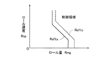
次に、図11及び図12を参照して、故障時ロール増大傾向判定基準の設定について説明する。以下においては左旋回を示す第1象限の特性のみを示すが、右旋回は原点0について対称の特性として設定される。図11に実線で示すように、サスペンション制御装置が故障したと判定されたときのロール増大傾向判定基準Ref1xは、ステップ100において設定されるロール増大傾向判定基準の初期特性Ref1oよりも、小さい値となる特性に変更される。この結果、ローリング運動を安定化するための制動力制御及び駆動力制御が、より小さいロール状態量においても実行されるようになるため、サスペンション制御装置が故障しても車両のロール増大傾向は抑制される。
Next, with reference to FIG. 11 and FIG. 12, the setting of the roll increasing tendency judgment criterion at the time of failure will be described. In the following, only the characteristics of the first quadrant showing the left turn are shown, but the right turn is set as a symmetrical characteristic with respect to the origin 0. As indicated by a solid line in FIG. 11, the roll increase tendency determination criterion Ref1x when it is determined that the suspension control device has failed is smaller than the initial characteristic Ref1o of the roll increase tendency determination criterion set in
また、サスペンション特性には、大別するとサスペンションストロークに依存して力を発生するばね要素(コイルばね、エアばね、スタビライザ等)とストローク速度に依存して力を発生する減衰要素(ショックアブソーバ等)とに分類される。そして、主として、ロール量Rmgはばね要素に、ロール速度Rspは減衰要素に、それぞれ対応して得られる状態量であるため、どちらの要素に該当するサスペンション制御装置が故障したかによって、ロール増大傾向判定基準の変更の方法も変えることができる。 The suspension characteristics can be broadly divided into spring elements (coil springs, air springs, stabilizers, etc.) that generate force depending on the suspension stroke, and damping elements (shock absorber, etc.) that generate force depending on the stroke speed. And classified. Since the roll amount Rmg is a state amount obtained corresponding to the spring element and the roll speed Rsp is respectively corresponding to the damping element, the roll increasing tendency depends on which element the suspension control device has failed. The method for changing the judgment criteria can also be changed.
例えば、図12に示すように、ばね要素が故障した場合にはロール量Rmgが小さいときでも制御領域となるように、サスペンション制御装置が正常時のロール増大傾向判定特性Ref1oは、ロール量方向(図12のX軸方向)に小さくしたRef1xsの特性(一点鎖線)に変更される。一方、減衰要素が故障した場合には、ロール増大傾向判定特性Ref1oが、ロール速度方向(図12のY軸方向)に小さくしたRef1xdの特性(実線)に変更される。而して、サスペンション制御装置の機能に応じて、故障時のロール増大傾向判定特性を変更することができる。 For example, as shown in FIG. 12, when the spring element fails, the roll increase tendency determination characteristic Ref1o when the suspension control device is normal is in the roll amount direction ( The characteristic is changed to the Ref1xs characteristic (dashed line) reduced in the X-axis direction in FIG. On the other hand, when the damping element fails, the roll increase tendency determination characteristic Ref1o is changed to the Ref1xd characteristic (solid line) that is reduced in the roll speed direction (Y-axis direction in FIG. 12). Thus, the roll increase tendency determination characteristic at the time of failure can be changed according to the function of the suspension control device.
上記図11及び図12では、故障時ロール増大傾向判定基準Ref1x及びRef2xを、ロール増大傾向判定基準の初期特性Ref1o及びRef2oとは異なる特性として設定することとしているが、ロール増大傾向判定基準の初期特性をサスペンション制御装置が故障した場合も見込んだ特性とし、故障時ロール増大傾向判定基準とロール増大傾向判定基準の初期特性とを同一の特性とすることもできる。この場合、サスペンション制御装置が正常と判定されているときには、ロール増大傾向判定基準は初期特性Ref1o及びRef2oから、実際の車両状態に適合した特性Ref1及びRef2に変更されるが、サスペンション制御装置が故障と判定されると、Ref1及びRef2から初期特性Ref1o及びRef2oに戻される。 In FIG. 11 and FIG. 12, the roll increase tendency determination criteria Ref1x and Ref2x at the time of failure are set as characteristics different from the initial characteristics Ref1o and Ref2o of the roll increase tendency determination criteria. It is also possible to set the characteristic to be a characteristic that is expected even when the suspension control device fails, and the initial characteristic of the roll increase tendency determination criterion and the roll increase tendency determination criterion at the time of failure can be the same characteristic. In this case, when it is determined that the suspension control device is normal, the roll increase tendency determination criterion is changed from the initial characteristics Ref1o and Ref2o to the characteristics Ref1 and Ref2 adapted to the actual vehicle state, but the suspension control apparatus fails. Is determined, the initial characteristics Ref1o and Ref2o are returned from Ref1 and Ref2.
前述のように、サスペンション制御装置を備えた車両においては、サスペンション制御装置の制御状態に応じてロール増大傾向判定基準が設定され、サスペンション特性に応じたローリング運動安定化制御が行われる。図2を参照して説明したように、乗員の増加や積載条件の変化などによって車両重心位置が変化し、車両のロール増大傾向の現われ易さを示す特性(ロール指標)が変化するが、サスペンション制御装置の制御状態に応じて、車両のロール増大傾向の現われ易さを、精度良く求めることができる。以下に説明するロール指標の推定は、図7に示すステップ107よりも前に処理され、その結果(ロール指標)がロール増大傾向判定基準の設定に反映される。
As described above, in a vehicle equipped with a suspension control device, a roll increase tendency determination criterion is set according to the control state of the suspension control device, and rolling motion stabilization control is performed according to suspension characteristics. As described with reference to FIG. 2, the position of the center of gravity of the vehicle changes due to an increase in occupants, changes in loading conditions, etc., and the characteristic (roll index) indicating the tendency of the vehicle to increase its roll changes. According to the control state of the control device, it is possible to accurately determine the ease of appearance of the vehicle roll increase tendency. The roll index estimation described below is processed before
先ず、車両のローリング運動は、下記の(5)式の運動方程式で表すことができる。
Ix・d2φ/dt2+Cx・dφ/dt+Kx・φ
= Ms・Hs・Gy+Ms・g・Hs・φ …(5)
ここで、φはロール角、Ixはロール慣性質量、Cxはロール減衰、Kxはロール剛性、Msは車両のばね上質量、Hsはロールアーム長(車両重心位置におけるロールセンタ軸から重心高までの距離)、Gyは横加速度、gは重力加速度である。
First, the rolling motion of the vehicle can be expressed by the following equation of motion (5).
Ix · d 2 φ / dt 2 + Cx · dφ / dt + Kx · φ
= Ms · Hs · Gy + Ms · g · Hs · φ (5)
Where φ is the roll angle, Ix is the roll inertia mass, Cx is the roll damping, Kx is the roll stiffness, Ms is the sprung mass of the vehicle, and Hs is the roll arm length (from the roll center axis to the center of gravity height at the vehicle center of gravity position). Distance), Gy is the lateral acceleration, and g is the gravitational acceleration.
上記(5)式において、車両のロール角φはそれ程には大きくならないため、右辺の第2項は無視することができる。そして、(5)式をラプラス変換して、ロール角φの伝達関数を求めると、下記の(6)式となる。
φ(s)/Gy(s) =(Ms・Hs)/(Ix・s2+Cx・s+Kx) …(6)
ここで、sはラプラス演算子である。
In the above formula (5), since the roll angle φ of the vehicle does not become so large, the second term on the right side can be ignored. Then, when Laplace transform is performed on the equation (5) to obtain the transfer function of the roll angle φ, the following equation (6) is obtained.
φ (s) / Gy (s) = (Ms · Hs) / (Ix · s 2 + Cx · s + Kx) (6)
Here, s is a Laplace operator.
更に、(6)式に基づきロール角速度Rrの伝達関数を求めると下記(7)式となる。
Rr(s)/Gy(s) =(Ms・Hs・s)/(Ix・s2+Cx・s+Kx)
…(7)
Further, when the transfer function of the roll angular velocity Rr is obtained based on the equation (6), the following equation (7) is obtained.
Rr (s) / Gy (s) = (Ms · Hs · s) / (Ix · s 2 + Cx · s + Kx)
... (7)
上記(6)式及び(7)式から明らかなように、横加速度に対する車両のローリング運動の伝達関数に基づいてロール角及びロール角速度を求めた結果と、車両運動の出力として検出されるロール角及びロール角速度とを比較することによって、係数(Ms・Hs)を求めることができる。そして、係数(Ms・Hs)は、重心位置の特性を含む値であるため、これをロール指標RIとすることができる。 As is apparent from the above equations (6) and (7), the roll angle and roll angular velocity obtained based on the transfer function of the rolling motion of the vehicle with respect to the lateral acceleration, and the roll angle detected as the output of the vehicle motion And the coefficient (Ms · Hs) can be obtained by comparing the roll angular velocity. Since the coefficient (Ms · Hs) is a value including the characteristics of the center of gravity, this can be used as the roll index RI.
また、車両のばね上質量Msは、車輪に作用する制動力と車両の減速度から推定することができる。そこで、車両の減速のたびに車両ばね上質量Msを推定し、ロールアーム長Hsを求め、これをロール指標RIとすることもできる。 The sprung mass Ms of the vehicle can be estimated from the braking force acting on the wheels and the deceleration of the vehicle. Therefore, each time the vehicle is decelerated, the vehicle sprung mass Ms is estimated to determine the roll arm length Hs, which can be used as the roll index RI.
図13は横加速度とロール角速度の伝達関数に基づいてロール指標を求める場合を示している。即ち、横加速度センサGYによって検出される横加速度Gyを用い上記の(7)式に基づいて推定ロール角速度Rreを演算する。そして、ロール角速度センサRRによって検出されるロール角速度Rrと、推定ロール角速度Rreとを比較することによってロール指標RIを演算することができる。この場合において、上記の(7)式におけるロール減衰Cx及びロール剛性Kxの値は、サスペンション制御装置の制御状態に基づいて決定される。 FIG. 13 shows a case where a roll index is obtained based on a transfer function of lateral acceleration and roll angular velocity. That is, the estimated roll angular velocity Rre is calculated based on the above equation (7) using the lateral acceleration Gy detected by the lateral acceleration sensor GY. Then, the roll index RI can be calculated by comparing the roll angular velocity Rr detected by the roll angular velocity sensor RR with the estimated roll angular velocity Rre. In this case, the roll damping Cx and the roll stiffness Kx in the above equation (7) are determined based on the control state of the suspension control device.
また、図14は横加速度とロール角の伝達関数に基づいてロール指標を求める場合を示している。即ち、横加速度センサGYによって検出される横加速度Gyを用い上記の(6)式に基づいて推定ロール角Raeを演算する。そして、サスペンションストロークセンサSTxxによって検出されるサスペンションストロークStxxから、左右サスペンションのストローク差を求め、ロール角Raを演算する。そして、これと推定ロール角Raeとを比較することによってロール指標RIを演算することができる。この場合において、上記の(6)式におけるロール減衰Cx及びロール剛性Kxの値は、サスペンション制御装置の制御状態に基づいて決定される。 FIG. 14 shows a case where the roll index is obtained based on the transfer function of the lateral acceleration and the roll angle. That is, the estimated roll angle Rae is calculated based on the above equation (6) using the lateral acceleration Gy detected by the lateral acceleration sensor GY. Then, from the suspension stroke Stxx detected by the suspension stroke sensor STxx, the stroke difference between the left and right suspensions is obtained, and the roll angle Ra is calculated. The roll index RI can be calculated by comparing this with the estimated roll angle Rae. In this case, the roll damping Cx and the roll stiffness Kx in the above equation (6) are determined based on the control state of the suspension control device.
上記図13及び図14においては、横加速度を用い、ローリング運動の伝達関数によって演算される推定ロール出力状態量と、車両のローリング運動の結果として検出されるロール出力状態量(以下、検出ロール出力状態量という)とを比較してロール指標を求めることとしている。この場合に、結果としてのローリング運動はロール角速度センサRRやサスペンションストロークセンサSTxx等から直接的に求めることができる。更に、ローリング運動の結果として生じる種々の検出状態量に基づいて演算することも可能である。例えば、サスペンションストローク速度によってロール角速度を、又は、ロール角速度からロール角を演算することも可能である。また、横加速度センサを車両の上下方向に所定の距離をおいて配置し、複数の横加速度センサによる検出横加速度の差から検出ロール出力状態量を求めることができる。更には、ローリング運動が発生すると、車載の横加速度センサはロール角のため重力加速度の成分も検出することになるが、この現象を利用して前述の(1)式で求まるヨー角速度による演算横加速度Gy1と、横加速度センサGYで検出される横加速度Gyとを比較して検出ロール出力状態量を求めることもできる。 13 and 14, the estimated roll output state quantity calculated by the transfer function of the rolling motion using the lateral acceleration and the roll output state quantity detected as a result of the rolling motion of the vehicle (hereinafter, detected roll output). (Referred to as state quantity) to obtain a role index. In this case, the resulting rolling motion can be obtained directly from the roll angular velocity sensor RR, the suspension stroke sensor STxx, and the like. Furthermore, it is also possible to perform calculations based on various detected state quantities generated as a result of the rolling motion. For example, the roll angular velocity can be calculated from the suspension stroke speed, or the roll angle can be calculated from the roll angular velocity. Further, the lateral acceleration sensor is arranged at a predetermined distance in the vertical direction of the vehicle, and the detected roll output state quantity can be obtained from the difference between the lateral accelerations detected by the plurality of lateral acceleration sensors. Furthermore, when a rolling motion occurs, the in-vehicle lateral acceleration sensor detects the gravitational acceleration component because of the roll angle, and this phenomenon is used to calculate the lateral velocity calculated by the above-mentioned equation (1). The detected roll output state quantity can also be obtained by comparing the acceleration Gy1 with the lateral acceleration Gy detected by the lateral acceleration sensor GY.
次に、ロール角速度を用いたロール指標RIの演算処理について、図15を参照して説明する。前述のステップ100の初期化処理において、ロール指標はその初期値RIoに設定される。ローリング運動を安定化するための制動力制御及び駆動力制御が行われ易いように、ロール指標の初期値RIoはロール増大傾向が現われ易い、より安定側の値として設定される。また、ロール指標RIは、所定のロール状態量以上のローリング運動が発生する旋回時に推定される。このように、ロール指標の推定を旋回毎に行うのではなく、所定のロール状態量以上の場合に行うこととしているので、ロール指標の推定誤差を小さく抑えることができる。
Next, the calculation process of the roll index RI using the roll angular velocity will be described with reference to FIG. In the initialization process of
図15において、ステップ150では、読み込まれたセンサ信号及び通信信号に基づき、前掲の[表1]に示す車両のロール状態量Rstが演算される。そして、ステップ151において、車両のローリング運動に関し、ロール指標の推定が可能な程度の大きさか否かを判定するために、ロール状態量Rstが所定値と比較される。ロール状態量Rstが所定値以上ではないと判定されると、ロール指標は推定されず、従ってロール指標の変更は行われず、従前の制御サイクルでのロール指標の値が維持される。
In FIG. 15, in
ステップ151において、ロール状態量が所定値以上であると判定されるとステップ152以降に進み、ロール指標の推定が行われる。ステップ152乃至154においては、図13に示した手段によってロール指標RIが演算される。そして、ステップ155に進み、ステップ154で演算されたロール指標RIに基づき、従前のロール指標からの変更が行われる。このように、車両のロール増大傾向の現われ易さを示すロール指標RIが、サスペンション制御装置の制御状態に応じて演算されるため、精度良くロール指標を求めることができる。
If it is determined in
ステップ155のロール指標RIの変更においては、演算された値に直ちに変更することなく、段階的に変更することもできる。ロール指標RIの推定演算には誤差が含まれる場合もあるため、旋回毎に演算されたロール指標に基づいて順次変更を行うことで、誤差の影響を緩和し、推定のロバスト性を向上することができる。
In changing the roll index RI in
次に、ロール指標の変更の一例について図16のタイムチャートを参照して説明すると、ロール指標の変更の幅に制限を設け、今回推定されたロール指標RI(n)と、前回制御サイクルのロール指標RIとの差が所定値Kri以上の場合には、ロール指標を所定値Kriだけ変更することとしている。図16においては、ロール指標の初期値RIoから段階的にロール指標の設定変更が行われる状態を時系列で示している。ここで、図15のステップ150及び151のロール状態量としてロール角速度を用い、その絶対値がRr1以上となった場合にロール指標の推定演算を行うこととしている。
Next, an example of the roll index change will be described with reference to the time chart of FIG. 16. The roll index change range is limited, and the roll index RI (n) estimated this time and the roll of the previous control cycle are set. When the difference from the index RI is equal to or greater than the predetermined value Kri, the roll index is changed by the predetermined value Kri. In FIG. 16, the state in which the setting of the roll index is changed stepwise from the initial value RIo of the roll index is shown in time series. Here, the roll angular velocity is used as the roll state quantity in
即ち、ロール指標は初期値RIoに設定され、最初の旋回が行われると、初回のロール指標の推定が行われる。このときロール指標がRIaとして推定された場合でも、ロール指標は直ちにRIoからRIaには変更されず、RIaに近づく(ロール指標が減少する)方向に、所定値Kriだけ減少される(t1時)。そして、第2回目のローリング運動において、ロール指標が再びRIaと推定されると、ロール指標は更にRIaに近づく方向に、所定値Kriだけ減少される(t2時)。このように、ロール指標は徐々にRIaに漸近するように変更される。 That is, the roll index is set to the initial value RIo, and when the first turn is performed, the first roll index is estimated. At this time, even if the roll index is estimated as RIa, the roll index is not immediately changed from RIo to RIa, but is decreased by a predetermined value Kri in a direction approaching RIa (the roll index decreases) (at time t1). . Then, in the second rolling motion, when the roll index is estimated again as RIa, the roll index is further decreased by a predetermined value Kri in a direction approaching RIa (at time t2). In this way, the roll index is changed so as to gradually approach RIa.
また、ロール指標の変更の他の例として、今回推定されたロール指標RI(n)と前回制御サイクルのロール指標RIとの差の所定割合Wriを以って、下記の(8)式に基づきロール指標を変更することもできる。
RI ← RI−Wri・{RI−RI(n)} …(8)
ここで、Wriは定数であって、1より小さい値である。
As another example of the change of the roll index, a predetermined ratio Wri of the difference between the roll index RI (n) estimated this time and the roll index RI of the previous control cycle is used, based on the following equation (8). The role index can also be changed.
RI ← RI-Wri · {RI-RI (n)} (8)
Here, Wri is a constant and a value smaller than 1.
このように、前回制御サイクルのロール指標と今回制御サイクルのロール指標の推定値とを比較して、その偏差の所定割合Wriを変更することにより、誤差による不適切な推定の影響を排除し、ロール指標をその真値に漸近させることができる。尚、図16では、車両のローリング運動としてロール角速度に着目したが、図14に示すようにロール角に基づいてロール指標RIを推定演算することもできる。ロール指標RIの推定は、横加速度に基づく推定ロール角又は推定ロール角速度と、車両のローリング運動の結果として得られるロール角又はロール角速度との比較において行われるため、変動要素である車輪と路面の摩擦条件が排除され、信頼性の高い推定を行うことができる。更に、推定されたロール指標には直ちに変更せず、変更幅の制限値又は変更比率を設けて、段階的に変更を行うこととしているため、ロバストな推定を行うことができる。 Thus, by comparing the roll index of the previous control cycle with the estimated value of the roll index of the current control cycle and changing the predetermined ratio Wri of the deviation, the influence of inappropriate estimation due to error is eliminated, The roll index can be asymptotic to its true value. In FIG. 16, the roll angular velocity is focused on as the rolling motion of the vehicle. However, as shown in FIG. 14, the roll index RI can be estimated and calculated based on the roll angle. Since the roll index RI is estimated by comparing the estimated roll angle or the estimated roll angular speed based on the lateral acceleration with the roll angle or the roll angular speed obtained as a result of the rolling motion of the vehicle, Friction conditions are eliminated and reliable estimation can be performed. Furthermore, since the estimated roll index is not changed immediately, but a change range limit value or change ratio is provided and changes are made in stages, robust estimation can be performed.
SCM サスペンション制御装置
M0 サスペンション特性取得手段
M1 ローリング運動検出手段
M2 横加速度検出手段
M3 ローリング運動推定手段
M4 ロール指標推定手段
M5 ロール増大傾向判定基準設定手段
M6 制御手段
M7 故障判定手段M7
ECU1 ブレーキ系電子制御ユニット
ECU2 エンジン系電子制御ユニット
ECU3 インパネ系電子制御ユニット
ECU4 エアサスペンション系電子制御ユニット
ECU5 ショックアブソーバ系電子制御ユニット
ECU6 スタビライザ系電子制御ユニット
SA 操舵角センサ
GX 前後加速度センサ
GY 横加速度センサ
YR ヨー角速度センサ
RR ロール角速度センサ
BRK ブレーキアクチュエータ
BP ブレーキペダル
AP アクセルペダルセンサ
SCM suspension control device M0 suspension characteristic acquisition means M1 rolling motion detection means M2 lateral acceleration detection means M3 rolling motion estimation means M4 roll index estimation means M5 roll increase tendency determination criterion setting means M6 control means M7 failure determination means M7
ECU 1 Brake system electronic control unit ECU 2 Engine system electronic control unit ECU 3 Instrument panel system electronic control unit ECU 4 Air suspension system electronic control unit ECU 5 Shock absorber system electronic control unit ECU 6 Stabilizer system electronic control unit SA Steering angle sensor GX Longitudinal acceleration sensor GY Lateral acceleration sensor YR Yaw angular velocity sensor RR Roll angular velocity sensor BRK Brake actuator BP Brake pedal AP Accelerator pedal sensor
Claims (4)
Failure determination means for determining failure of the suspension control device is provided, and the roll increase tendency determination criterion setting means changes and sets the determination criterion of the roll increase tendency of the vehicle based on the determination result of the failure determination means. The rolling motion stabilization control device for a vehicle according to claim 2 or 3.
Priority Applications (1)
| Application Number | Priority Date | Filing Date | Title |
|---|---|---|---|
| JP2005161516A JP2006335193A (en) | 2005-06-01 | 2005-06-01 | Rolling characteristic estimation device for vehicle, and rolling motion stabilization controller for vehicle using the same |
Applications Claiming Priority (1)
| Application Number | Priority Date | Filing Date | Title |
|---|---|---|---|
| JP2005161516A JP2006335193A (en) | 2005-06-01 | 2005-06-01 | Rolling characteristic estimation device for vehicle, and rolling motion stabilization controller for vehicle using the same |
Publications (1)
| Publication Number | Publication Date |
|---|---|
| JP2006335193A true JP2006335193A (en) | 2006-12-14 |
Family
ID=37556109
Family Applications (1)
| Application Number | Title | Priority Date | Filing Date |
|---|---|---|---|
| JP2005161516A Pending JP2006335193A (en) | 2005-06-01 | 2005-06-01 | Rolling characteristic estimation device for vehicle, and rolling motion stabilization controller for vehicle using the same |
Country Status (1)
| Country | Link |
|---|---|
| JP (1) | JP2006335193A (en) |
Cited By (14)
| Publication number | Priority date | Publication date | Assignee | Title |
|---|---|---|---|---|
| JP2009214742A (en) * | 2008-03-11 | 2009-09-24 | Nissan Motor Co Ltd | Lane deviation preventive device and its method |
| JP2010540329A (en) * | 2007-10-04 | 2010-12-24 | ダイムラー・アクチェンゲゼルシャフト | Gas spring system with multi-chamber gas spring |
| JP2011068177A (en) * | 2009-09-24 | 2011-04-07 | Advics Co Ltd | Motion control device for vehicle |
| CN102307739A (en) * | 2009-02-16 | 2012-01-04 | 丰田自动车株式会社 | Stabilizer control device for vehicle |
| JP2012011995A (en) * | 2010-02-16 | 2012-01-19 | Equos Research Co Ltd | Vehicle |
| JP2012012004A (en) * | 2010-02-16 | 2012-01-19 | Equos Research Co Ltd | Vehicle |
| JP2012148631A (en) * | 2011-01-18 | 2012-08-09 | Equos Research Co Ltd | Vehicle |
| JP2012153348A (en) * | 2011-01-28 | 2012-08-16 | Equos Research Co Ltd | Vehicle |
| JPWO2010134251A1 (en) * | 2009-05-21 | 2012-11-08 | アイシン精機株式会社 | Vehicle ground load control device |
| JP2013071549A (en) * | 2011-09-27 | 2013-04-22 | Honda Motor Co Ltd | Vehicle stability assist |
| WO2013100122A1 (en) * | 2011-12-28 | 2013-07-04 | 日産自動車株式会社 | Vehicle control device |
| WO2013111736A1 (en) * | 2012-01-25 | 2013-08-01 | 日産自動車株式会社 | Vehicle control system and vehicle control method |
| CN115158282A (en) * | 2022-06-28 | 2022-10-11 | 一汽奔腾轿车有限公司 | Active safety system for reducing risk of out-of-control yaw in high-speed running of vehicle |
| WO2023238598A1 (en) * | 2022-06-09 | 2023-12-14 | 株式会社アイシン | Vehicle control device |
Citations (7)
| Publication number | Priority date | Publication date | Assignee | Title |
|---|---|---|---|---|
| JPH08127333A (en) * | 1994-10-31 | 1996-05-21 | Nissan Motor Co Ltd | Antiskid control device for vehicle provided with yawing momentum control device |
| JPH08132839A (en) * | 1994-11-08 | 1996-05-28 | Toyota Motor Corp | Vehicle suspension control device |
| JP2000219146A (en) * | 1999-02-01 | 2000-08-08 | Toyota Motor Corp | Vehicle travel control device |
| JP2001050973A (en) * | 1999-08-04 | 2001-02-23 | Denso Corp | Method and device for estimating and for controlling behavior of vehicle |
| JP2004262410A (en) * | 2003-03-04 | 2004-09-24 | Denso Corp | Starting device of occupant protecting device |
| JP2005001522A (en) * | 2003-06-12 | 2005-01-06 | Nissan Motor Co Ltd | Sidelong falldown determining method of vehicle, and sidelong falldown determining device of vehicle |
| JP2005028918A (en) * | 2003-07-08 | 2005-02-03 | Toyota Motor Corp | Risk judging device for rollover of vehicle |
-
2005
- 2005-06-01 JP JP2005161516A patent/JP2006335193A/en active Pending
Patent Citations (7)
| Publication number | Priority date | Publication date | Assignee | Title |
|---|---|---|---|---|
| JPH08127333A (en) * | 1994-10-31 | 1996-05-21 | Nissan Motor Co Ltd | Antiskid control device for vehicle provided with yawing momentum control device |
| JPH08132839A (en) * | 1994-11-08 | 1996-05-28 | Toyota Motor Corp | Vehicle suspension control device |
| JP2000219146A (en) * | 1999-02-01 | 2000-08-08 | Toyota Motor Corp | Vehicle travel control device |
| JP2001050973A (en) * | 1999-08-04 | 2001-02-23 | Denso Corp | Method and device for estimating and for controlling behavior of vehicle |
| JP2004262410A (en) * | 2003-03-04 | 2004-09-24 | Denso Corp | Starting device of occupant protecting device |
| JP2005001522A (en) * | 2003-06-12 | 2005-01-06 | Nissan Motor Co Ltd | Sidelong falldown determining method of vehicle, and sidelong falldown determining device of vehicle |
| JP2005028918A (en) * | 2003-07-08 | 2005-02-03 | Toyota Motor Corp | Risk judging device for rollover of vehicle |
Cited By (21)
| Publication number | Priority date | Publication date | Assignee | Title |
|---|---|---|---|---|
| JP2010540329A (en) * | 2007-10-04 | 2010-12-24 | ダイムラー・アクチェンゲゼルシャフト | Gas spring system with multi-chamber gas spring |
| JP2009214742A (en) * | 2008-03-11 | 2009-09-24 | Nissan Motor Co Ltd | Lane deviation preventive device and its method |
| CN102307739A (en) * | 2009-02-16 | 2012-01-04 | 丰田自动车株式会社 | Stabilizer control device for vehicle |
| JPWO2010134251A1 (en) * | 2009-05-21 | 2012-11-08 | アイシン精機株式会社 | Vehicle ground load control device |
| JP2011068177A (en) * | 2009-09-24 | 2011-04-07 | Advics Co Ltd | Motion control device for vehicle |
| JP2012011996A (en) * | 2010-02-16 | 2012-01-19 | Equos Research Co Ltd | Vehicle |
| JP2012012004A (en) * | 2010-02-16 | 2012-01-19 | Equos Research Co Ltd | Vehicle |
| CN102770333A (en) * | 2010-02-16 | 2012-11-07 | 爱考斯研究株式会社 | Vehicle |
| JP2012011995A (en) * | 2010-02-16 | 2012-01-19 | Equos Research Co Ltd | Vehicle |
| JP2012148631A (en) * | 2011-01-18 | 2012-08-09 | Equos Research Co Ltd | Vehicle |
| JP2012153348A (en) * | 2011-01-28 | 2012-08-16 | Equos Research Co Ltd | Vehicle |
| JP2013071549A (en) * | 2011-09-27 | 2013-04-22 | Honda Motor Co Ltd | Vehicle stability assist |
| WO2013100122A1 (en) * | 2011-12-28 | 2013-07-04 | 日産自動車株式会社 | Vehicle control device |
| CN104024076A (en) * | 2011-12-28 | 2014-09-03 | 日产自动车株式会社 | Vehicle control device |
| JP5668873B2 (en) * | 2011-12-28 | 2015-02-12 | 日産自動車株式会社 | Vehicle control device |
| US9187080B2 (en) | 2011-12-28 | 2015-11-17 | Nissan Motor Co., Ltd. | Control apparatus for vehicle |
| WO2013111736A1 (en) * | 2012-01-25 | 2013-08-01 | 日産自動車株式会社 | Vehicle control system and vehicle control method |
| JPWO2013111736A1 (en) * | 2012-01-25 | 2015-05-11 | 日産自動車株式会社 | Vehicle control apparatus and vehicle control method |
| US9415657B2 (en) | 2012-01-25 | 2016-08-16 | Nissan Motor Co., Ltd. | Vehicle control device and vehicle control method |
| WO2023238598A1 (en) * | 2022-06-09 | 2023-12-14 | 株式会社アイシン | Vehicle control device |
| CN115158282A (en) * | 2022-06-28 | 2022-10-11 | 一汽奔腾轿车有限公司 | Active safety system for reducing risk of out-of-control yaw in high-speed running of vehicle |
Similar Documents
| Publication | Publication Date | Title |
|---|---|---|
| JP2006335193A (en) | Rolling characteristic estimation device for vehicle, and rolling motion stabilization controller for vehicle using the same | |
| US8718872B2 (en) | Vehicle attitude controller | |
| JP4631549B2 (en) | Vehicle motion stabilization control device | |
| JP5809474B2 (en) | Body posture control device | |
| US7715963B2 (en) | Stabilizer control apparatus | |
| US20080269974A1 (en) | Method for Controlling the Driving Dynamics of a Vehicle, Device for Implementing the Method and Use Thereof | |
| JP4639925B2 (en) | Rolling motion stabilization control device for vehicle | |
| KR102172306B1 (en) | Apparatus for controlling the behavior of vehicle | |
| KR101288749B1 (en) | Driving condition adapted to the steering engagement based on vehicle dynamic control | |
| AU2016201638B2 (en) | Vibration control device and vibration control system | |
| JP4721100B2 (en) | Rolling motion stabilization control device for vehicle | |
| JP4650080B2 (en) | Rolling motion stabilization control device for vehicle | |
| JP2006298209A (en) | Vehicle roll increase trend determination device and vehicle motion stabilization controller using the same | |
| KR102589031B1 (en) | Control unit of active suspension and control method of active suspension | |
| KR102463701B1 (en) | System and Method for calculating movement of vehicle | |
| JP5808615B2 (en) | Suspension control device | |
| JP4442092B2 (en) | Vehicle motion control device | |
| JP2006089005A (en) | Vehicle behavior control device | |
| JP2006335192A (en) | Rolling characteristic estimation device for vehicle, and rolling motion stabilization controller for vehicle using the same | |
| JP2008105472A (en) | Vibration control device for vehicle | |
| JP2022129649A (en) | Vehicle motion control device, vehicle motion control system and vehicle | |
| WO2023210533A1 (en) | Vehicle control device | |
| JP5157683B2 (en) | Suspension control device | |
| JPH07253367A (en) | Detector for frictional coefficient of road surface | |
| JP6003523B2 (en) | Vehicle behavior control apparatus and vehicle behavior control method |
Legal Events
| Date | Code | Title | Description |
|---|---|---|---|
| A621 | Written request for application examination |
Free format text: JAPANESE INTERMEDIATE CODE: A621 Effective date: 20071219 |
|
| A977 | Report on retrieval |
Free format text: JAPANESE INTERMEDIATE CODE: A971007 Effective date: 20090515 |
|
| A131 | Notification of reasons for refusal |
Free format text: JAPANESE INTERMEDIATE CODE: A131 Effective date: 20090526 |
|
| A521 | Written amendment |
Free format text: JAPANESE INTERMEDIATE CODE: A523 Effective date: 20090717 |
|
| A02 | Decision of refusal |
Free format text: JAPANESE INTERMEDIATE CODE: A02 Effective date: 20100323 |