JP2006326160A - Game machine - Google Patents

Game machine Download PDF

Info

Publication number
JP2006326160A
JP2006326160A JP2005157188A JP2005157188A JP2006326160A JP 2006326160 A JP2006326160 A JP 2006326160A JP 2005157188 A JP2005157188 A JP 2005157188A JP 2005157188 A JP2005157188 A JP 2005157188A JP 2006326160 A JP2006326160 A JP 2006326160A
Authority
JP
Japan
Prior art keywords
winning combination
value
symbol
stop
combination
Prior art date
Legal status (The legal status is an assumption and is not a legal conclusion. Google has not performed a legal analysis and makes no representation as to the accuracy of the status listed.)
Pending
Application number
JP2005157188A
Other languages
Japanese (ja)
Other versions
JP2006326160A5 (en
Inventor
Yoshinori Saito
芳典 齊藤
Takahiro Murakami
隆博 村上
Masahide Aoki
政英 青木
Yusuke Kondo
祐介 近藤
Takayuki Hara
隆之 原
Seiki Morishima
清貴 森島
Masaya Ando
真彌 安藤
Current Assignee (The listed assignees may be inaccurate. Google has not performed a legal analysis and makes no representation or warranty as to the accuracy of the list.)
Universal Entertainment Corp
Original Assignee
Aruze Corp
Priority date (The priority date is an assumption and is not a legal conclusion. Google has not performed a legal analysis and makes no representation as to the accuracy of the date listed.)
Filing date
Publication date
Application filed by Aruze Corp filed Critical Aruze Corp
Priority to JP2005157188A priority Critical patent/JP2006326160A/en
Publication of JP2006326160A publication Critical patent/JP2006326160A/en
Publication of JP2006326160A5 publication Critical patent/JP2006326160A5/ja
Pending legal-status Critical Current

Links

Images

Abstract

<P>PROBLEM TO BE SOLVED: To provide a game machine which can satisfy the requests both from players and game parlors by employing a new lottery system of winning combinations for creating novel fun as a break through of fixed concepts among players while enabling an effective step to be taken against the fraudulance. <P>SOLUTION: In a Pachislot machine 1, minor winning combinations of 'BB2' and 'cherry' and those of 'BB1' and 'water melon' partially overlap in a numerical range on an internal lottery table for the ordinary game state (Fig.9 (a)). In other words, when the number of slotted tokens is three, a numerical range from the lower limit value 0 to the upper limit value 599 is allotted to the winning number 1 corresponding to the minor winning combination of the 'cherry' and a numerical range from the lower limit value 579 to the upper limit value 661 partially overlapping the above range is allotted to the winning number 5 corresponding to that of 'BB2'. A numerical range from the lower limit value 1785 to the upper limit value 2184 is allotted to the winning number 3 corresponding to the minor winning combination of 'water melon' and a numerical range from the lower limit value 1730 to the upper limit value 1812 partially overlapping the above range is allotted to the winning number 6 corresponding to that of the 'BB1'. <P>COPYRIGHT: (C)2007,JPO&INPIT

Description

本発明は、遊技者による開始操作の検出に基づいて複数の当選役の中から抽選で当選役を決定する遊技機に関するものである。   The present invention relates to a gaming machine that determines a winning combination by lottery from a plurality of winning combinations based on detection of a start operation by a player.

従来、このような遊技機としては、リールの回転を遊技者の操作に応じて停止させるパチスロ機がある。一般的にパチスロ機では、遊技価値であるメダルがメダル投入口に投入されてスタートレバーが操作されると、抽選で当選役が決定されると共に複数のリールが回転を開始する。各リールの回転が一定速度に達した後に停止ボタンが操作されると、操作された停止ボタンに対応するリールが回転を停止する。全てのリールの回転が停止したときに抽選で決定された当選役に対応する図柄組合せが揃っていると、メダルが遊技価値として遊技者に付与される。   Conventionally, as such a gaming machine, there is a pachislot machine that stops the rotation of a reel in accordance with a player's operation. Generally, in a pachislot machine, when a medal as a game value is inserted into a medal slot and a start lever is operated, a winning combination is determined by lottery and a plurality of reels start rotating. When the stop button is operated after the rotation of each reel reaches a certain speed, the reel corresponding to the operated stop button stops rotating. If the combination of symbols corresponding to the winning combination determined by lottery when all reels stop rotating, medals are awarded to the player as a gaming value.

特許文献1に開示されるパチスロ機では、当選役を決定する抽選は、確率抽選テーブルを用いた乱数抽選により行われる。確率抽選テーブルには、所定の乱数範囲の中から各当選役毎に異なる数値範囲が順に割り当てられている。乱数抽選では、各当選役に順に割り当てられた数値範囲の上限値を抽出乱数値から減算し、減算結果が負になると、その数値範囲に割り当てられた当選役がその単位遊技における当選役として決定される。一方、減算結果が正の場合には、減算結果が負になるまで、次の判別対象となる当選役の数値範囲の上限値について、同様の処理が行われる。
特開2002−78857号公報(段落[0093]〜[0098]、図15,図16参照)
In the pachislot machine disclosed in Patent Document 1, lottery for determining the winning combination is performed by random lottery using a probability lottery table. In the probability lottery table, different numerical ranges for each winning combination are sequentially assigned from a predetermined random number range. In the random lottery, the upper limit of the numerical range assigned to each winning combination is subtracted from the extracted random number value, and when the subtraction result becomes negative, the winning combination assigned to the numerical range is determined as the winning combination in the unit game. Is done. On the other hand, when the subtraction result is positive, the same processing is performed on the upper limit value of the winning combination to be determined next until the subtraction result becomes negative.
JP 2002-78857 A (see paragraphs [0093] to [0098], FIG. 15 and FIG. 16)

しかしながら、特許文献1に開示される従来のパチスロ機では、上記のように、各当選役に順に割り当てられた数値範囲の上限値を抽出乱数値から減算する演算を、各数値範囲の上限値毎に順に実行し、演算の結果得られる値が負であると当選役の抽選が終了していたため、1の乱数値が抽出されたことにより決定される内部当選役は1種類に限定されていた。このことは、遊技者にとっても固定概念化されており、当選役の新たな抽選方式が待望されていた。   However, in the conventional pachislot machine disclosed in Patent Document 1, as described above, the calculation for subtracting the upper limit value of the numerical range assigned to each winning combination from the extracted random number value is performed for each upper limit value of each numerical range. When the value obtained as a result of the calculation is negative, the lottery of the winning combination has been completed, so the internal winning combination determined by extracting one random number value was limited to one type. . This has become a fixed concept for the player, and a new lottery system for winning the role has been awaited.

また、当選役の決定はパチスロ機を設置する遊技店の収支に直結するため、それに係るセキュリティの向上は遊技店にとって重大な関心事であるが、上記従来のパチスロ機では、抽出乱数値が数値範囲の上限値を下回ることのみに基づき当選役が決定されており、払い出しのある入賞に係る当選役に割り当てられる数値範囲が数値の若い方に偏っていた。このため、不正行為により一定のタイミングで開始操作が繰り返された場合、偏った数値範囲にある乱数値が抽出され続け、本来予定されている確率以上に入賞に係る当選役が決定され続けて、遊技者に多くの遊技価値が付与される事態が生じ、パチスロ機を設置する遊技店の経営を悪化させてしまうという問題があった。   In addition, since the determination of the winning role is directly linked to the income and expenditure of the game store where the pachislot machine is installed, the improvement of security related to it is a serious concern for the game store. The winning combination was determined based solely on falling below the upper limit of the range, and the numerical range allocated to the winning combination related to payouts with a payout was biased toward younger numbers. For this reason, if the start operation is repeated at a certain timing due to cheating, random numbers in the biased numerical range will continue to be extracted, and the winning combination related to winning will be determined more than the originally planned probability, There was a problem that a lot of game value was given to the player, and the management of the game store where the pachislot machine was installed was deteriorated.

そこで、本発明は、当選役の新たな抽選方式をもたらすことにより遊技者の固定概念を打破して新たな面白味を生じさせると共に、不正行為への有効な対策を講じることが可能で、遊技者および遊技店の双方の要請を満足させることができる遊技機を提供することを目的とする。   Therefore, the present invention can bring about a new interest by overcoming the fixed concept of the player by introducing a new lottery system for the winning role, and can take effective measures against fraud. It is an object of the present invention to provide a gaming machine that can satisfy both of the demands of the game store.

このために本発明は、複数の図柄を表示する図柄表示手段と、遊技者による開始操作の検出を行う開始操作検出手段と、この開始操作検出手段により行われる開始操作の検出に基づいて所定の乱数範囲の中から乱数を抽出する乱数抽出手段と、所定の乱数範囲に含まれる数値範囲の下限値および上限値を当選役に応じて規定する抽選値規定手段と、乱数抽出手段により抽出された乱数の値を下限値と上限値との双方と比較して乱数抽出手段により抽出された乱数が数値範囲に属するか否かを判別する乱数値判別手段と、この乱数値判別手段により乱数抽出手段により抽出された乱数が数値範囲に属すると判別された場合にはその数値範囲に応じた当選役を決定する当選役決定手段と、開始操作検出手段により行われる開始操作の検出に基づいて図柄表示手段により表示される図柄の変動を行う図柄変動手段と、遊技者による停止操作の検出を行う停止操作検出手段と、この停止操作検出手段により行われる停止操作の検出と当選役決定手段により決定される当選役とに基づき図柄変動手段により行われる図柄の変動の停止制御を行う停止制御手段と、この停止制御手段による停止制御の結果図柄表示手段により予め定められた図柄組合せが停止表示されると遊技価値を付与する遊技価値付与手段とを備え、
抽選値規定手段は、ある当選役に応じた数値範囲とある当選役とは異なる他の当選役に応じた数値範囲とを少なくとも一部において重複させていることを特徴とする遊技機を構成した。
To this end, the present invention provides a predetermined display based on symbol display means for displaying a plurality of symbols, start operation detection means for detecting a start operation by a player, and detection of the start operation performed by the start operation detection means. Random number extraction means for extracting random numbers from the random number range, lottery value specifying means for specifying the lower and upper limits of the numerical range included in the predetermined random number range according to the winning combination, and the random number extraction means Random value discriminating means for discriminating whether the random number extracted by the random number extracting means belongs to the numerical range by comparing the random value with both the lower limit value and the upper limit value; Based on the detection of the start operation performed by the winning combination determining means for determining the winning combination corresponding to the numerical range and the start operation detecting means when it is determined that the random number extracted by The symbol change means for changing the symbol displayed by the symbol display means, the stop operation detection means for detecting the stop operation by the player, the detection of the stop operation performed by the stop operation detection means and the winning combination determination means Based on the determined winning combination, a stop control means for performing stop control of the change of the symbol performed by the symbol change means, and a symbol combination determined in advance by the symbol display means as a result of the stop control by the stop control means is stopped and displayed A game value giving means for giving a game value,
The lottery value defining means constitutes a gaming machine characterized in that a numerical range corresponding to a winning combination and a numerical range corresponding to another winning combination different from a winning combination are at least partially overlapped. .

この構成によれば、ある当選役に応じた数値範囲とこの当選役とは異なる他の当選役に応じた数値範囲とが少なくとも一部において重複して規定されているので、乱数抽出手段により抽出された乱数がこの重複した数値範囲に属すると、各数値範囲に応じたある当選役と他の当選役との複数の当選役が決定される。このため、1つの乱数値および1つの抽選値規定手段のみを用いて、一度に複数の当選役を決定することが可能な新たな当選役の抽選方式を提供することができる。また、抽選値規定手段を複数設ける必要がないので、ハードウエア資源を増加させる必要もない。   According to this configuration, a numerical range corresponding to a winning combination and a numerical range corresponding to another winning combination different from the winning combination are defined at least partially in duplicate, and therefore extracted by random number extraction means. When the random numbers thus obtained belong to this overlapping numerical range, a plurality of winning combinations of a winning combination and other winning combinations corresponding to each numerical range are determined. Therefore, it is possible to provide a new winning combination lottery system capable of determining a plurality of winning combinations at a time using only one random value and one lottery value defining means. Further, since it is not necessary to provide a plurality of lottery value defining means, it is not necessary to increase hardware resources.

また、各当選役に割り当てられる数値範囲は、下限値および上限値をもって定められるため、必ずしも順に設ける必要がなく、各数値範囲を重複させたり分散させて不規則に設けることが可能となる。このため、不正行為により一定のタイミングで開始操作が繰り返されても、抽出乱数値が入賞に係る当選役に応じた数値範囲に入り続けることはなくなる。よって、本来予定されている確率以上に入賞に係る当選役が決定され続けるといったことはなくなり、遊技機を設置する遊技店の経営を悪化させてしまうことがなくなる。   In addition, the numerical range assigned to each winning combination is determined by the lower limit value and the upper limit value, and thus does not necessarily need to be provided in order, and can be provided irregularly by overlapping or distributing the numerical ranges. For this reason, even if the start operation is repeated at a certain timing due to fraud, the extracted random number value does not continue to be in the numerical value range corresponding to the winning combination related to winning. Therefore, the winning combination relating to the winning is not determined more than the originally scheduled probability, and the management of the game store where the gaming machine is installed is not deteriorated.

この結果、当選役の新たな抽選方式をもたらすことにより遊技者の固定概念を打破して新たな面白味を生じさせると共に、不正行為への有効な対策を講じることが可能で、遊技者および遊技店の双方の要請を満足させることができる遊技機を提供することが可能となる。   As a result, by introducing a new lottery system for winning roles, it is possible to break down the fixed concept of players and create new fun, and to take effective measures against fraudulent acts. It is possible to provide a gaming machine that can satisfy both requirements.

また、本発明は、当選役決定手段により当選役として決定されたある当選役および他の当選役に対応するいずれかの図柄組合せが図柄表示手段により停止表示されない場合には、停止表示されない当選役に対応する図柄組合せが図柄表示手段により停止表示されるまでその当選役に関する情報を持ち越す持越手段を備え、
停止制御手段は、持越手段により持ち越された当選役にも基づき、図柄表示手段による図柄の変動表示を停止制御することを特徴とする。
In addition, the present invention is a winning combination that is not stopped and displayed when any symbol combination corresponding to a winning combination and other winning combination determined by the winning combination determining means is not stopped and displayed by the symbol display means. A carry-over means for carrying over information on the winning combination until the symbol combination corresponding to is stopped and displayed by the symbol display means,
The stop control means is characterized in that, based on the winning combination carried over by the carryover means, the symbol display by the symbol display means is controlled to stop.

この構成によれば、当選役として決定されたある当選役または他の当選役が持越手段により持ち越された場合には、持ち越されたある当選役または他の当選役にも基づき、図柄の変動表示が停止制御される。このため、ある当選役および他の当選役が決定された場合に、一方の当選役に応じた図柄の変動表示の停止制御のみが行われて、遊技者が他方の当選役に応じた図柄の変動表示の停止制御を享受できなくなり、不利益を被る事態を防ぐことができる。   According to this configuration, when a winning combination or other winning combination determined as a winning combination is carried over by means of carryover, the change display of the symbol is also made based on the selected winning combination or other winning combination. Is controlled to stop. For this reason, when a winning combination and another winning combination are determined, only the control of changing the display of the symbols according to one winning combination is performed, and the player has the symbol corresponding to the other winning combination. It becomes impossible to enjoy the stop control of the variable display, and it is possible to prevent a disadvantage.

このような本発明によれば、上記のように、遊技者および遊技店の双方の要請を満足させることができる遊技機を提供することが可能となる。   According to the present invention as described above, it is possible to provide a gaming machine capable of satisfying the demands of both the player and the gaming store as described above.

次に、本発明の最良の形態によるパチスロ機1について説明する。   Next, a pachislot machine 1 according to the best mode of the present invention will be described.

図1は本発明の最良の形態によるパチスロ機1の外観を示す正面図である。   FIG. 1 is a front view showing an appearance of a pachislot machine 1 according to the best mode of the present invention.

パチスロ機1の本体中央部には、3個のリール2〜4が回転自在に設けられている。各リール2〜4の外周面には複数種類の図柄(以下、シンボルという)から成るシンボル列が描かれている。これらシンボルはパチスロ機1の正面の表示窓5〜7を通してそれぞれ3個ずつ観察される。この表示窓5〜7には、横3本と斜め2本の計5本の入賞ラインL1,L2A,L2B,L3A,L3Bが設けられている。また、表示窓5〜7の下方右側には、遊技価値であるメダルが投入されるメダル投入口8が設けられている。リール2〜4および表示窓5〜7は、複数のシンボルを表示する図柄表示手段を構成している。   Three reels 2 to 4 are rotatably provided in the central portion of the main body of the pachi-slot machine 1. On the outer peripheral surface of each of the reels 2 to 4, a symbol row composed of a plurality of types of symbols (hereinafter referred to as symbols) is drawn. Three of these symbols are observed through the display windows 5 to 7 in front of the pachislot machine 1. The display windows 5 to 7 are provided with a total of five pay lines L1, L2A, L2B, L3A, and L3B. Further, on the lower right side of the display windows 5 to 7, there is provided a medal slot 8 into which a medal as a game value is inserted. The reels 2 to 4 and the display windows 5 to 7 constitute symbol display means for displaying a plurality of symbols.

ゲーム開始に先立って、遊技者がメダル投入口8から1枚のメダルを投入したときは、中央の横1本の入賞ラインL1が有効化される。また、2枚投入したときは、これに上下の横2本の入賞ラインL2A,L2Bが加わって横3本の入賞ラインL1,L2A,L2Bが有効化される。また、3枚投入したときは、これに斜め2本の入賞ラインL3A,L3Bが加わって5本の入賞ラインL1,L2A,L2B,L3A,L3Bの全てが有効化される。なお、以降、有効化された入賞ラインを有効化入賞ラインという。   Prior to the start of the game, when the player inserts one medal from the medal insertion slot 8, the central one winning line L1 is activated. In addition, when two cards are inserted, two upper and lower horizontal winning lines L2A and L2B are added to the three horizontal winning lines L1, L2A and L2B. In addition, when three cards are inserted, two diagonal winning lines L3A and L3B are added thereto, and all five winning lines L1, L2A, L2B, L3A and L3B are activated. Hereinafter, the activated winning line is referred to as an activated winning line.

また、表示窓5〜7の左方には、遊技動作表示器9〜12、BETランプ13〜15、貯留枚数表示部16、およびスタートランプ17が設けられている。各表示器9〜12およびBETランプ13〜15は遊技状況に応じて点灯制御され、そのときの遊技状況が遊技者に知らされる。貯留枚数表示部16は、3桁の7セグメントLEDからなり、機械内部のメダルカウンタに現在クレジットされているメダル数を表示する。スタートランプ17は各リール2〜4が作動可能な時に点滅する。   Further, game operation indicators 9 to 12, BET lamps 13 to 15, a stored number display unit 16, and a start lamp 17 are provided on the left side of the display windows 5 to 7. The indicators 9 to 12 and the BET lamps 13 to 15 are controlled to be turned on according to the game situation, and the player is notified of the game situation at that time. The stored number display unit 16 is made up of a three-digit 7-segment LED, and displays the number of medals currently credited on a medal counter inside the machine. The start lamp 17 blinks when the reels 2 to 4 are operable.

また、表示窓5〜7の右方には、上部から、ボーナスカウント表示部18、WINランプ19、配当枚数表示部20、およびインサートランプ21が設けられている。ボーナスカウント表示部18は、3桁の7セグメントLEDからなり、ボーナスゲーム作動時に、RBゲームの残り入賞可能回数などをデジタル表示する。WINランプ19は有効化入賞ラインにボーナスの作動に対応するシンボルが揃った時などに点灯する。配当枚数表示部20は、3桁の7セグメントLEDからなり、入賞によるメダル払い出し枚数を表示する。インサートランプ21はメダル投入口8にメダルの投入が受付可能な時に点灯する。   Further, on the right side of the display windows 5 to 7, a bonus count display section 18, a WIN lamp 19, a payout number display section 20, and an insert lamp 21 are provided from the top. The bonus count display section 18 is made up of a three-digit 7-segment LED, and digitally displays the remaining number of RB games that can be won when the bonus game is activated. The WIN lamp 19 is turned on when symbols corresponding to the bonus operation are arranged on the activated pay line. The number-of-payout display unit 20 is composed of a three-digit 7-segment LED and displays the number of medals to be paid out by winning. The insert lamp 21 is lit when a medal can be accepted at the medal slot 8.

また、表示窓5〜7の直ぐ下方には、液晶表示装置22が設けられている。液晶表示装置22の左側には十字キー23、「○」ボタン24、「×」ボタン25、1貯留メダル投入ボタン26、2貯留メダル投入ボタン27、および3貯留メダル投入ボタン28が設けられている。十字キー23は、上下左右の4方向の操作を検出して、液晶表示装置22に表示される情報項目を選択する際に使用される。「○」ボタン24は十字キー23によって選択された情報項目を決定するボタンであり、「×」ボタン25は十字キー23によって選択された情報項目をキャンセルするボタンである。また、貯留メダル投入ボタン26〜28は、貯留枚数表示部16にメダル数が表示され、クレジットされている際に、メダル投入口8へのメダル投入に代えて1回のゲームに1〜3枚のメダルを賭ける際に使用される。   A liquid crystal display device 22 is provided immediately below the display windows 5 to 7. On the left side of the liquid crystal display device 22, a cross key 23, a “o” button 24, an “x” button 25, a 1 stored medal insertion button 26, a 2 stored medal insertion button 27, and a 3 stored medal insertion button 28 are provided. . The cross key 23 is used when detecting an operation in four directions, up, down, left, and right, and selecting an information item displayed on the liquid crystal display device 22. The “◯” button 24 is a button for determining the information item selected by the cross key 23, and the “X” button 25 is a button for canceling the information item selected by the cross key 23. The stored medal insertion buttons 26 to 28 display 1 to 3 coins per game instead of inserting medals into the medal insertion slot 8 when the number of medals is displayed on the stored number display unit 16 and credited. Used when betting medals.

また、液晶表示装置22の下方には、左側から、貯留メダル精算ボタン29、スタートレバー30および停止ボタン31〜33が設けられている。貯留メダル精算ボタン29は機械内部にクレジットされているメダルを精算する際に使用される。スタートレバー30が遊技者に操作されることにより各リール2〜4の回転が一斉に開始する。停止ボタン31〜33は、各リール2〜4に対応して配置されており、これら各リール2〜4の回転が一定速度に達したときに操作が有効化され、遊技者の操作に応じて各リール2〜4の回転を停止する。   Further, below the liquid crystal display device 22, a stored medal settlement button 29, a start lever 30, and stop buttons 31 to 33 are provided from the left side. The stored medal settlement button 29 is used when the medal credited in the machine is settled. When the start lever 30 is operated by the player, the rotation of the reels 2 to 4 starts all at once. The stop buttons 31 to 33 are arranged corresponding to the respective reels 2 to 4, and the operation is activated when the rotation of each of the reels 2 to 4 reaches a constant speed, and according to the player's operation The rotation of each reel 2 to 4 is stopped.

また、パチスロ機1の正面下部にはメダル受皿37が設けられている。このメダル受皿37はメダル払出口38から払い出されるメダルを貯めるものである。また、パチスロ機1の正面上部には、入賞に対してどれだけのメダルが払い出されるかを示す配当表示部39が設けられており、この配当表示部39の左右には一対のスピーカ96,96が設けられている。   In addition, a medal tray 37 is provided at the lower front portion of the pachi-slot machine 1. The medal tray 37 stores medals paid out from the medal payout opening 38. In addition, a payout display unit 39 indicating how many medals are paid out in response to a prize is provided at the upper front portion of the pachislot machine 1. A pair of speakers 96, 96 are provided on the left and right sides of the payout display unit 39. Is provided.

各リール2〜4は図2に示す回転リールユニットとして構成されており、フレーム41にブラケット42を介して取り付けられている。各リール2〜4はリールドラム43の外周にリール帯44が貼られて構成されている。リール帯44の外周面にはシンボル列が描かれている。また、各ブラケット42にはステッピングモータ45が設けられており、各リール2〜4はこれらステッピングモータ45が駆動されて回転する。   Each reel 2 to 4 is configured as a rotary reel unit shown in FIG. 2 and is attached to a frame 41 via a bracket 42. Each of the reels 2 to 4 has a reel band 44 attached to the outer periphery of the reel drum 43. A symbol row is drawn on the outer peripheral surface of the reel band 44. Each bracket 42 is provided with a stepping motor 45, and the reels 2 to 4 are rotated by driving the stepping motor 45.

各リール2〜4の構造は図3に示される。なお、同図において図2と同一部分には同一符号を付してその説明は省略する。同図(a)に示すように、リール帯44の背後のリールドラム43内部にはランプケース46が設けられており、このランプケース46の3個の各部屋にはそれぞれリールバックランプ47a〜47cが取り付けられている。これらバックランプ47a〜47cは、同図(b)に示すように、異なる複数の色を発光するLED47が基板48に取り付けられて構成されており、基板48はランプケース46の背面に取り付けられている。また、ブラケット42にはホトセンサ49が取り付けられている。このホトセンサ49は、リールドラム43に設けられた遮蔽板50がリールドラム43の回転に伴ってホトセンサ49を通過するのを検出する。   The structure of each reel 2-4 is shown in FIG. In the figure, the same parts as those in FIG. As shown in FIG. 5A, a lamp case 46 is provided inside the reel drum 43 behind the reel band 44. Reel back lamps 47a to 47c are provided in the three rooms of the lamp case 46, respectively. Is attached. These back lamps 47a to 47c are configured such that LEDs 47 that emit a plurality of different colors are attached to a substrate 48, as shown in FIG. 5B, and the substrate 48 is attached to the back surface of the lamp case 46. Yes. A photo sensor 49 is attached to the bracket 42. The photo sensor 49 detects that the shielding plate 50 provided on the reel drum 43 passes through the photo sensor 49 as the reel drum 43 rotates.

各バックランプ47a〜47cは後述するランプ駆動回路89(図6参照)によって点灯制御される。各バックランプ47a〜47cの点灯により、リール帯44に描かれたシンボルの内、各バックランプ47の前部に位置する3個のシンボルが背後から個別に照らし出され、各表示窓5〜7にそれぞれ3個ずつのシンボルが映し出される。   Each of the back lamps 47a to 47c is controlled to be lit by a lamp driving circuit 89 (see FIG. 6) described later. When the back lamps 47a to 47c are turned on, among the symbols drawn on the reel band 44, three symbols positioned at the front of each back lamp 47 are individually illuminated from behind, and the display windows 5 to 7 are illuminated. Three symbols are projected on each.

図4は、左,中,右の各リール2〜4の各リール帯44に表された複数種類のシンボルが、21個配列されたシンボル列を示している。各シンボルには“0”〜“20”のコードナンバーが付され、これらコードナンバーは、データテーブルとして後で説明するプログラムROM65(図5参照)に格納されている。各リール2〜4上には、“赤7”、“リプレイ”、“スイカ”、“ベル”、“チェリー”、“BAR”、および何も描かれていない「ブランク」のシンボルで構成されるシンボル列が表されている。各リール2〜4は、シンボル列が図の矢印方向に移動するように回転駆動される。   FIG. 4 shows a symbol row in which 21 types of symbols represented on the reel bands 44 of the left, middle, and right reels 2 to 4 are arranged. Each symbol is assigned a code number “0” to “20”, and these code numbers are stored in a program ROM 65 (see FIG. 5) described later as a data table. On each reel 2-4, it is composed of "red 7", "replay", "watermelon", "bell", "cherry", "BAR", and "blank" symbols with nothing drawn on them. A symbol column is represented. Each reel 2 to 4 is rotationally driven so that the symbol row moves in the direction of the arrow in the figure.

本実施形態によるパチスロ機1の遊技状態には、「一般遊技状態」、「BB(ビッグ・ボーナス)内部当選状態」および「RB遊技状態」がある。これら5種類の各遊技状態は、基本的に、内部当選する可能性のある役の種類、および、成立させることが可能なボーナスの種別により区別される。   The gaming state of the pachislot machine 1 according to the present embodiment includes “general gaming state”, “BB (big bonus) internal winning state”, and “RB gaming state”. Each of these five game states is basically distinguished by the type of winning combination that may be won internally and the type of bonus that can be established.

BB1またはBB2に対応するシンボルの組合せが有効化入賞ライン上に表示されたことを契機として発生し得る、「RB遊技状態」により構成される遊技状態を総称して、以下「BB遊技状態」という。「BB内部当選状態」は、ボーナスに内部当選していまだそのボーナスに対応するシンボルの組合せが有効化入賞ラインに表示されていない状態であり、以下「内部当選状態」という。「BB1」のボーナス当たり要求フラグ、または「BB2」の当たり要求フラグは、フラグが立てられた以降の遊技に持ち越され、「BB1」または「BB2」のシンボル組み合わせが有効化入賞ラインに停止表示されてボーナスが実際に成立すると、ボーナス当たり要求フラグはクリアされる。また、ボーナス当たり要求フラグ以外のフラグは、フラグが立てられた遊技においてのみ有効であり、その遊技終了時にはクリアされて次遊技以降には持ち越されない。なお、内部当選役を持ち越すとは、内部抽選処理(図20,S8)で決定された内部当選役としての機能を次以降の単位遊技において発揮できるようにすれば足り、種々の態様が適宜可能である。例えば、本実施の形態のように、所定内部当選役のフラグをクリアし、他のフラグを利用して、内部当選役の機能が発揮されるまで、持ち越すこともできる。   The gaming state composed of “RB gaming state” that can be triggered by the combination of symbols corresponding to BB1 or BB2 being displayed on the activated pay line is hereinafter collectively referred to as “BB gaming state”. . The “BB internal winning state” is a state in which a bonus combination is not yet displayed on the activated winning line, and the symbol combination corresponding to the bonus has not yet been displayed. The bonus request flag of “BB1” or the hit request flag of “BB2” is carried over to the game after the flag is set, and the symbol combination of “BB1” or “BB2” is stopped and displayed on the activated pay line. When the bonus is actually established, the bonus request flag is cleared. Flags other than the bonus requirement flag are valid only in the game in which the flag is set, and are cleared at the end of the game and are not carried over after the next game. To carry over the internal winning combination is sufficient as long as the function as the internal winning combination determined in the internal lottery process (FIG. 20, S8) can be exhibited in the following unit games, and various modes are possible as appropriate. It is. For example, as in the present embodiment, a predetermined internal winning combination flag can be cleared, and other flags can be used until the internal winning combination function is exhibited.

図5および図6は、上述したパチスロ機1の遊技処理動作を制御するメイン制御基板61およびサブ制御基板62に構成された回路構成を示している。   5 and 6 show circuit configurations configured on the main control board 61 and the sub control board 62 that control the game processing operation of the pachislot machine 1 described above.

図5に示すメイン制御基板61における制御部はマイクロコンピュータ(以下、マイコンという)63を主な構成要素とし、これに乱数サンプリングのための回路を加えて構成されている。マイコン63は、予め設定されたプログラムに従って制御動作を行うメインCPU(中央演算処理装置)64と、プログラム記憶手段であるプログラムROM(リード・オンリ・メモリ)65およびバックアップ機能付き制御RAM(ランダム・アクセス・メモリ)66とを含んで構成されている。   The control unit in the main control board 61 shown in FIG. 5 includes a microcomputer (hereinafter referred to as a microcomputer) 63 as a main component, and is added with a circuit for random number sampling. The microcomputer 63 includes a main CPU (central processing unit) 64 that performs a control operation according to a preset program, a program ROM (read only memory) 65 that is a program storage means, and a control RAM (random access) with a backup function. -Memory) 66.

メインCPU64には、基準クロックパルスを発生するクロックパルス発生回路67および分周器68と、一定範囲の乱数を発生する乱数発生器69および発生した乱数の1つを特定するサンプリング回路70とが接続されている。さらに、後述する周辺装置(アクチュエータ)との間で信号を授受するI/Oポート(入出力ポート)71が接続されている。   Connected to the main CPU 64 are a clock pulse generating circuit 67 and a frequency divider 68 for generating a reference clock pulse, a random number generator 69 for generating a random number in a certain range, and a sampling circuit 70 for specifying one of the generated random numbers. Has been. Further, an I / O port (input / output port) 71 for transmitting / receiving a signal to / from a peripheral device (actuator) described later is connected.

プログラムROM65は、各種テーブルやシーケンスプログラム等を格納するように記憶部が区分されている。また、プログラムROM65内には図示しない入賞シンボル組合せテーブルが格納されている。この入賞シンボル組合せテーブルには、配当表示部39に示される各入賞シンボル組合せのシンボルコードや、「リーチ目」を構成するシンボル組合せのシンボルコード、各入賞を表す入賞判定コード、入賞メダル配当枚数等が記憶されている。ここで、リーチ目とは、内部当選状態のときに、遊技者にボーナスの作動に係るシンボルの組合せを表示可能であることを示唆するシンボル組合せである。この入賞シンボル組合せテーブルは、リール2〜4の停止制御時、および全リール停止後の表示役検索を行うときに参照される。さらに、プログラムROM65内には、このパチスロ機1でゲームを実行するためのシーケンスプログラムが格納されている。   The program ROM 65 has a storage section that stores various tables, sequence programs, and the like. The program ROM 65 stores a winning symbol combination table (not shown). In this winning symbol combination table, the symbol code of each winning symbol combination displayed on the payout display unit 39, the symbol code of the symbol combination constituting the “reach eye”, the winning determination code representing each winning, the number of winning medal dividends, etc. Is remembered. Here, the reach eye is a symbol combination that suggests that a combination of symbols related to the operation of the bonus can be displayed to the player in the internal winning state. This winning symbol combination table is referred to during stop control of the reels 2 to 4 and when searching for a display combination after all reels are stopped. Further, in the program ROM 65, a sequence program for executing a game with the pachislot machine 1 is stored.

マイコン63からの制御信号により動作が制御される主要なアクチュエータとしては、各リール2〜4を回転駆動するステッピングモータ45、各種ランプ(BETランプ13〜15、スタートランプ17、WINランプ19、インサートランプ21)、各種表示部(遊技動作表示器9〜12、貯留枚数表示部16、ボーナスカウント表示部18、配当枚数表示部20)、およびメダルを収納するホッパー72がある。これらはそれぞれモータ駆動回路73、各ランプ駆動回路74、各表示部駆動回路75、およびホッパー駆動回路76によって駆動される。これら駆動回路73〜76は、マイコン63のI/Oポート71を介してメインCPU64に接続されている。   The main actuators whose operation is controlled by a control signal from the microcomputer 63 include a stepping motor 45 that rotationally drives the reels 2 to 4, various lamps (BET lamps 13 to 15, a start lamp 17, a WIN lamp 19, an insert lamp. 21), various display units (game operation indicators 9 to 12, stored number display unit 16, bonus count display unit 18, payout number display unit 20), and hopper 72 for storing medals. These are driven by a motor drive circuit 73, each lamp drive circuit 74, each display unit drive circuit 75, and a hopper drive circuit 76, respectively. These drive circuits 73 to 76 are connected to the main CPU 64 via the I / O port 71 of the microcomputer 63.

また、マイコン63が制御信号を生成するために必要な入力信号を発生する主な入力信号発生手段としては、メダル投入口8から投入されたメダルを検出する投入メダルセンサ8S、スタートレバー30の操作を検出するスタートスイッチ30S、貯留メダル投入ボタン26〜28の操作を検出する貯留メダル投入スイッチ26S〜28S、および貯留メダル精算ボタン29の操作を検出する貯留メダル精算スイッチ29Sがある。スタートスイッチ30Sは、遊技者によるスタートレバー30の開始操作の検出を行う開始操作検出手段を構成している。   As main input signal generating means for generating an input signal necessary for the microcomputer 63 to generate a control signal, the inserted medal sensor 8S for detecting a medal inserted from the medal slot 8 and the operation of the start lever 30 are used. There are a start switch 30S for detecting the stored medal, a stored medal insertion switch 26S-28S for detecting the operation of the stored medal insertion button 26-28, and a stored medal adjustment switch 29S for detecting the operation of the stored medal adjustment button 29. The start switch 30S constitutes start operation detection means for detecting the start operation of the start lever 30 by the player.

さらに、上記の入力信号発生手段としては、ホトセンサ49からの出力パルス信号を受けて各リール2〜4の回転位置を検出するリール位置検出回路77がある。ホトセンサ49は各リール2〜4の駆動機構に含まれており、同図では示されていない。   Further, as the input signal generating means, there is a reel position detection circuit 77 that receives the output pulse signal from the photosensor 49 and detects the rotational position of each reel 2-4. The photo sensor 49 is included in the driving mechanism of each reel 2 to 4 and is not shown in the figure.

リール位置検出回路77は、リール2〜4の回転が開始された後、ステッピングモータ45の各々に供給される駆動パルスの数を計数し、この計数値を制御RAM66の所定エリアに書き込む。従って、制御RAM66内には、各リール2〜4について、1回転の範囲内における回転位置に対応した計数値が格納されている。また、ホトセンサ49は各リール2〜4が1回転する毎にリセットパルスを発生する。このリセットパルスはリール位置検出回路77を介してメインCPU64に与えられ、制御RAM66で計数されている駆動パルスの計数値が“0”にクリアされる。このクリア処理により、各シンボルの移動表示と各ステッピングモータ45の回転との間に生じるずれが、1回転毎に解消されている。ステッピングモータ45、モータ駆動回路73、リール位置検出回路77、およびマイコン63は、開始操作検出手段により行われる開始操作の検出に基づいて図柄表示手段により表示されるシンボルの変動を行う図柄変動手段を構成している。   The reel position detection circuit 77 counts the number of drive pulses supplied to each of the stepping motors 45 after the rotation of the reels 2 to 4 is started, and writes this count value in a predetermined area of the control RAM 66. Accordingly, the control RAM 66 stores a count value corresponding to the rotation position within one rotation range for each of the reels 2 to 4. The photo sensor 49 generates a reset pulse every time the reels 2 to 4 make one rotation. This reset pulse is given to the main CPU 64 via the reel position detection circuit 77, and the count value of the drive pulse counted by the control RAM 66 is cleared to "0". By this clearing process, the deviation generated between the movement display of each symbol and the rotation of each stepping motor 45 is eliminated every rotation. The stepping motor 45, the motor drive circuit 73, the reel position detection circuit 77, and the microcomputer 63 have symbol variation means for varying the symbol displayed by the symbol display means based on the detection of the start operation performed by the start operation detection means. It is composed.

さらに、上記の入力信号発生手段としては、停止ボタン31〜33が押された時に対応するリール2〜4を停止させる信号を発生するリール停止信号回路78、ホッパー72から払い出されるメダル数を計数するメダル検出部72S、および図示しない払出完了信号発生回路がある。これらもI/Oポート71を介してメインCPU64に接続されている。払出完了信号発生回路は、メダル検出部72Sから入力した実際に払い出しのあったメダル計数値が、各表示部駆動回路75から入力した計数信号で表される配当枚数データに達した時に、メダル払い出しの完了を検知する信号を発生する。リール停止信号回路78は、遊技者による停止ボタン31〜33の停止操作の検出を行う停止操作検出手段を構成している。ステッピングモータ45、モータ駆動回路73、リール位置検出回路77、リール停止信号回路78、およびマイコン63は、停止操作検出手段により行われる停止操作の検出と、後述する当選役決定手段により決定される当選役とに基づき、図柄変動手段により行われるシンボルの変動の停止制御を行う停止制御手段を構成している。マイコン63、ホッパー72、メダル検出部72s、ホッパー駆動回路76、および払出完了信号発生回路は、停止制御手段による停止制御の結果、図柄表示手段により予め定められたシンボル組合せが停止表示されると遊技価値をメダルとして付与する遊技価値付与手段を構成している。   Further, as the input signal generating means, the reel stop signal circuit 78 for generating a signal for stopping the corresponding reels 2 to 4 when the stop buttons 31 to 33 are pressed, and the number of medals paid out from the hopper 72 are counted. There are a medal detection unit 72S and a payout completion signal generation circuit (not shown). These are also connected to the main CPU 64 via the I / O port 71. The payout completion signal generation circuit pays out medals when the actually paid out medal count value input from the medal detection unit 72S reaches the payout number data represented by the count signal input from each display unit drive circuit 75. Generates a signal to detect completion of The reel stop signal circuit 78 constitutes stop operation detecting means for detecting stop operation of the stop buttons 31 to 33 by the player. The stepping motor 45, the motor drive circuit 73, the reel position detection circuit 77, the reel stop signal circuit 78, and the microcomputer 63 detect the stop operation performed by the stop operation detecting means and the winning determined by the winning combination determining means described later. Based on the combination, stop control means is configured to perform stop control of symbol fluctuation performed by the symbol changing means. The microcomputer 63, the hopper 72, the medal detection unit 72s, the hopper driving circuit 76, and the payout completion signal generation circuit are played when a predetermined symbol combination is stopped and displayed by the symbol display means as a result of the stop control by the stop control means. It constitutes game value giving means for giving a value as a medal.

また、I/Oポート71にはサブ制御部通信ポート79が接続されており、マイコン63はこのサブ制御部通信ポート79を介してサブ制御基板62へ信号を送出する。図6に示すサブ制御基板62には、この信号を受信するメイン制御部通信ポート88が設けられている。サブ制御部通信ポート79およびメイン制御部通信ポート88間の通信は、サブ制御部通信ポート79からメイン制御部通信ポート88へ向かう一方向についてだけ行われる。本実施形態では、サブ制御部通信ポート79からメイン制御部通信ポート88へ送出される信号は、7ビット長でその制御種別が表されるコマンド種別と、最大24ビット長でそのコマンドの内容が表されるパラメータとで構成されている。   A sub-control unit communication port 79 is connected to the I / O port 71, and the microcomputer 63 sends a signal to the sub-control board 62 via the sub-control unit communication port 79. The sub control board 62 shown in FIG. 6 is provided with a main control unit communication port 88 for receiving this signal. Communication between the sub control unit communication port 79 and the main control unit communication port 88 is performed only in one direction from the sub control unit communication port 79 to the main control unit communication port 88. In the present embodiment, the signal sent from the sub-control unit communication port 79 to the main control unit communication port 88 is a 7-bit command type indicating the control type and a maximum 24-bit length command content. It is composed of the parameters represented.

サブ制御基板62は、メイン制御基板61からの制御信号に基づき所定の演出を行う。サブ制御基板62における制御部はマイコン81を主な構成要素として構成されている。マイコン81も、メイン制御基板61におけるマイコン63と同様、予め設定されたプログラムに従って制御動作を行うサブCPU82と、プログラム記憶手段であるプログラムROM83およびバックアップ機能付き制御RAM84とを含んで構成されている。サブCPU82にも、基準クロックパルスを発生するクロックパルス発生回路85および分周器86が接続されており、さらに、上記のメイン制御部通信ポート88や後述するアクチュエータとの間で信号を授受するI/Oポート87が接続されている。   The sub control board 62 performs a predetermined effect based on a control signal from the main control board 61. The control unit in the sub-control board 62 is configured with the microcomputer 81 as a main component. Similarly to the microcomputer 63 on the main control board 61, the microcomputer 81 includes a sub CPU 82 that performs a control operation according to a preset program, a program ROM 83 that is a program storage unit, and a control RAM 84 with a backup function. A clock pulse generation circuit 85 for generating a reference clock pulse and a frequency divider 86 are also connected to the sub CPU 82. Further, the sub CPU 82 further transmits / receives signals to / from the main control unit communication port 88 and an actuator described later. / O port 87 is connected.

また、マイコン81からの制御信号により動作が制御されるアクチュエータとして、各リール2〜4に内蔵されたリールバックランプ47a〜47cがある。これらバックランプ47a〜47cの点灯は、I/Oポート87に接続されたランプ駆動回路89からの駆動信号によって制御される。   As actuators whose operation is controlled by a control signal from the microcomputer 81, there are reel back lamps 47a to 47c built in the reels 2 to 4, respectively. Lighting of these back lamps 47 a to 47 c is controlled by a drive signal from a lamp drive circuit 89 connected to the I / O port 87.

また、マイコン81が制御信号を生成するために必要な入力信号を発生する入力信号発生手段として、前述した十字キー23、「○」ボタン24および「×」ボタン25がある。   Further, as the input signal generating means for generating an input signal necessary for the microcomputer 81 to generate a control signal, there are the above-described cross key 23, “◯” button 24 and “×” button 25.

また、I/Oポート87には画像制御ワークRAM98、VDP(ビデオ・ディスプレイ・プロセッサ)90および音源IC91が接続されている。VDP90には、キャラクタ・データが記憶されたキャラクタROM92およびカラーディスプレイ表示用バッファメモリであるビデオRAM93が接続されており、画像制御ワークRAM98も接続されている。VDP90は、マイコン81の制御の下、液晶表示装置22に画像表示を行う。   The I / O port 87 is connected to an image control work RAM 98, a VDP (video display processor) 90, and a sound source IC 91. The VDP 90 is connected to a character ROM 92 storing character data, a video RAM 93 which is a color display display buffer memory, and an image control work RAM 98 is also connected. The VDP 90 displays an image on the liquid crystal display device 22 under the control of the microcomputer 81.

また、音源IC91にはサウンド・データが記憶されたサウンドROM94が接続されており、音源IC91は、マイコン81の制御の下、パワーアンプ95を介してスピーカ96,96からサウンドを放音させる。マイコン81は、メイン制御部通信ポート88を介してメイン制御基板61から入力される指示に従い、音源IC91およびパワー・アンプ95を制御し、メダル投入音,スタートレバー操作音,停止ボタン操作音,ボーナスゲーム中の遊技音といった効果音をスピーカ96,96から出力させる。また、メイン制御基板61から取り込んだ遊技状態および当選フラグに基づいて選択した演出態様に基づく出音パターンで、スピーカ96,96から出音させる。   In addition, a sound ROM 94 storing sound data is connected to the sound source IC 91, and the sound source IC 91 emits sound from the speakers 96 and 96 through the power amplifier 95 under the control of the microcomputer 81. The microcomputer 81 controls the sound source IC 91 and the power amplifier 95 in accordance with instructions input from the main control board 61 via the main control unit communication port 88, and controls the medal insertion sound, start lever operation sound, stop button operation sound, bonus Sound effects such as game sounds during the game are output from the speakers 96 and 96. In addition, sound is output from the speakers 96, 96 in a sound output pattern based on the game state fetched from the main control board 61 and an effect mode selected based on the winning flag.

図7〜図14は、メイン制御基板61のプログラムROM65に記憶された各種テーブルを示す図である。   7 to 14 are diagrams showing various tables stored in the program ROM 65 of the main control board 61. FIG.

図7は、シンボル組合せテーブルを概念的に示す図である。   FIG. 7 conceptually shows the symbol combination table.

シンボル組合せテーブルは、後述するメインフローチャート(図20参照)のS15において、表示役およびメダル払出枚数を特定する際に用いられる。シンボル組合せテーブルは、左リール2,中リール3,右リール4について有効化入賞ライン上に表示されたシンボル組合せとメダル払出枚数(配当)と表示役との関係を記憶している。同図において各リール2〜4の欄に表されるシンボルの組合せが有効化入賞ライン上に表示されると、対応する払出枚数欄に表される枚数および表示役欄に表される表示役が、メダル払出枚数および表示役として特定される。   The symbol combination table is used to specify the display combination and the medal payout number in S15 of the main flowchart (see FIG. 20) described later. The symbol combination table stores the relationship among the symbol combination displayed on the activated pay line for the left reel 2, the middle reel 3, and the right reel 4, the medal payout number (payout), and the display combination. In the same figure, when the combination of symbols represented in each of the reels 2 to 4 columns is displayed on the activated pay line, the number displayed in the corresponding payout number column and the display combination represented in the display combination column are displayed. The medal payout number and the display combination are specified.

同図に示すように、“チェリー−ANY−ANY”が有効化入賞ラインに沿って並ぶと「チェリー」の小役が表示役として特定され、投入枚数が1枚および2枚の場合にはそれぞれ15枚、投入枚数が3枚の場合には4枚が払出枚数として特定される。なお、「ANY」はどのシンボルでもよいことを表す。また、投入枚数は単位遊技に賭けられているメダル枚数のことをいう。また、“ベル−ベル−ベル”が有効化入賞ラインに沿って並ぶと「ベル」の小役が表示役として特定され、投入枚数が1枚および2枚の場合にはそれぞれメダル15枚、投入枚数が3枚の場合には6枚が払出枚数として特定される。また、“スイカ−スイカ−スイカ”が有効化入賞ラインに沿って並ぶと「スイカ」の小役が表示役として特定され、投入枚数が1枚〜3枚の何れの場合にも、12枚が払出枚数として特定される。また、“リプレイ−リプレイ−リプレイ”が有効化入賞ラインに沿って並ぶと、「リプレイ」が表示役として特定され、払出枚数としてメダル0枚が特定されてその単位遊技で遊技に賭けられた枚数と同じ枚数のメダルが、次の単位遊技で自動投入される。また、“赤7−赤7−赤7”が有効化入賞ラインに沿って並ぶと「BB1」が表示役として特定され、投入枚数が1枚〜3枚の何れの場合にも、払出枚数としてメダル0枚が特定されて、BB遊技状態が作動する。また、“BAR−BAR−BAR”が有効化入賞ラインに沿って並ぶと「BB2」が表示役として特定され、投入枚数が1枚〜3枚の何れの場合にも、払出枚数としてメダル0枚が特定されて、BB遊技状態が作動する。   As shown in the figure, when “Cherry-ANY-ANY” is lined up along the activated pay line, the “Cherry” small role is specified as the display role, and when the number of throws is 1 and 2 respectively, When 15 sheets are inserted and 3 sheets are inserted, 4 sheets are specified as the number of sheets to be paid out. Note that “ANY” represents any symbol. The number of inserted coins refers to the number of medals bet on a unit game. In addition, when “Bell-Bell-Bell” is lined up along the activated pay line, the “Bell” small role is specified as the display role, and when the number of inserted coins is 1 or 2, 15 medals are inserted respectively. If the number is three, six is specified as the number of payouts. In addition, when “Watermelon-Watermelon-Watermelon” is lined up along the activated winning line, the small combination of “Watermelon” is specified as the display combination, and in any case where the number of inserted sheets is 1 to 3, It is specified as the number of payouts. In addition, when “Replay-Replay-Replay” is arranged along the activated pay line, “Replay” is specified as a display combination, 0 medals are specified as the number of payouts, and the number of bets placed on the game in the unit game The same number of medals will be automatically inserted in the next unit game. In addition, when “Red 7-Red 7-Red 7” are arranged along the activated pay line, “BB1” is specified as a display combination, and the number of payouts is 1 to 3 in any case The 0 medals are specified and the BB gaming state is activated. In addition, when “BAR-BAR-BAR” is arranged along the activated pay line, “BB2” is specified as a display combination, and in the case where the number of inserted coins is 1 to 3, 0 medals are paid out. Is identified and the BB gaming state is activated.

図8は、内部抽選テーブル決定テーブルを概念的に示す図である。この内部抽選テーブル決定テーブルは、後述する内部抽選処理(図20,S8)において、内部当選役を抽選する回数を決定する際に用いられる。このテーブルでは、一般遊技状態およびRB遊技状態の各遊技状態毎に、抽選回数、および抽選に用いる内部抽選テーブルの種別を表す数値データが割り当てられている。後述する内部抽選処理では、各遊技状態に対応する内部抽選テーブルを用いて、数値データが表す抽選回数だけ抽選が行われる。一般遊技状態には、抽選回数6回および一般遊技状態用内部抽選テーブルを表すデータが割り当てられており、一般遊技状態中の各単位遊技では、抽選回数として6回、内部抽選テーブルとして一般遊技状態用内部抽選テーブルが決定される。RB遊技状態には、抽選回数3回およびRB遊技状態用内部抽選テーブルを表すデータが割り当てられており、RB遊技状態中の各単位遊技では、抽選回数として3回、内部抽選処理に用いられる内部抽選テーブルとしてRB遊技状態用内部抽選テーブルが決定される。   FIG. 8 is a diagram conceptually showing the internal lottery table determination table. This internal lottery table determination table is used in determining the number of times to win the internal winning combination in the internal lottery process (FIG. 20, S8) described later. In this table, numerical data representing the number of lotteries and the type of the internal lottery table used for the lottery is assigned to each gaming state of the general gaming state and the RB gaming state. In an internal lottery process to be described later, lottery is performed for the number of lotteries represented by numerical data using an internal lottery table corresponding to each gaming state. Data representing the number of lottery times 6 and the internal lottery table for the general gaming state is assigned to the general gaming state. In each unit game in the general gaming state, the number of lottery times is six, and the general gaming state is the internal lottery table. An internal lottery table is determined. In the RB gaming state, data representing the number of times of lottery three times and the internal lottery table for the RB gaming state are allocated. In each unit game in the RB gaming state, the number of times of lottery is three times, and the internal lottery process is used. An RB gaming state internal lottery table is determined as the lottery table.

図9は、内部抽選テーブルを概念的に示す図である。   FIG. 9 is a diagram conceptually showing the internal lottery table.

内部抽選テーブルは、後述するメインフローチャートの内部抽選処理(図20,S8)において、内部当選役を抽選する際に用いられる。内部抽選テーブルは、乱数発生器69で発生してサンプリング回路70で抽出された0〜65535の所定範囲の乱数を、各当選番号1〜6に区分けする数値データを下限値および上限値として記憶している。各当選番号は各内部当選役に対応づけられており、数値データは各投入枚数毎に記憶されている。各当選番号1〜6には、0〜65535の数値データの中から各数値範囲を規定する上限値および下限値が対で各遊技状態毎に割り当てられており、抽出された乱数値が属する数値範囲に割り当てられた当選番号が選択される。   The internal lottery table is used when an internal winning combination is drawn in the internal lottery process (FIG. 20, S8) of the main flowchart described later. The internal lottery table stores numerical data that divides the random numbers in a predetermined range of 0 to 65535 generated by the random number generator 69 and extracted by the sampling circuit 70 into the respective winning numbers 1 to 6 as the lower limit value and the upper limit value. ing. Each winning number is associated with each internal winning combination, and numerical data is stored for each inserted number. Each winning number 1 to 6 is assigned a pair of an upper limit value and a lower limit value that define each numerical range among numerical data of 0 to 65535 for each gaming state, and a numerical value to which the extracted random number value belongs. The winning number assigned to the range is selected.

同図(a)に示す一般遊技状態用内部抽選テーブルでは、「チェリー」の小役に対応する当選番号1には、投入枚数が1枚および2枚の場合にはそれぞれ下限値0,上限値0、投入枚数が3枚の場合には下限値0,上限値599の数値範囲が割り当てられている。投入枚数が1枚および2枚の場合の当選確率は1/65536、投入枚数が3枚の場合の当選確率は600/65536である。また、「ベル」の小役に対応する当選番号2には、投入枚数が1枚の場合には下限値28,上限値2027、投入枚数が2枚の場合には下限値118,上限値3117、投入枚数が3枚の場合には下限値2184,上限値7883の数値範囲がそれぞれ割り当てられている。投入枚数が1枚の場合の当選確率は2000/65536、投入枚数が2枚の場合の当選確率は3000/65536、投入枚数が3枚の場合の当選確率は5700/65536である。また、「スイカ」の小役に対応する当選番号3には、投入枚数が1枚の場合には下限値28,上限値28、投入枚数が2枚の場合には下限値118,上限値118、投入枚数が3枚の場合には下限値1785,上限値2184の数値範囲がそれぞれ割り当てられている。投入枚数が1枚の場合の当選確率は1/65536、投入枚数が2枚の場合の当選確率は1/65536、投入枚数が3枚の場合の当選確率は400/65536である。また、「リプレイ」に対応する当選番号4には、投入枚数が1枚の場合には下限値2027,上限値11006、投入枚数が2枚の場合には下限値3117,上限値12096、投入枚数が3枚の場合には下限値7883,上限値16862の数値範囲がそれぞれ割り当てられている。投入枚数が1枚の場合の当選確率は8980/65536、投入枚数が2枚の場合の当選確率は8980/65536、投入枚数が3枚の場合の当選確率は8980/65536である。また、「BB2」に対応する当選番号5には、投入枚数が1枚の場合には下限値1,上限値10、投入枚数が2枚の場合には下限値1,上限値40、投入枚数が3枚の場合には下限値579,上限値661の数値範囲がそれぞれ割り当てられている。投入枚数が1枚の場合の当選確率は10/65536、投入枚数が2枚の場合の当選確率は40/65536、投入枚数が3枚の場合の当選確率は83/65536である。また、「BB1」に対応する当選番号6には、投入枚数が1枚の場合には下限値19,上限値28、投入枚数が2枚の場合には下限値79,上限値118、投入枚数が3枚の場合には下限値1730,上限値1812の数値範囲がそれぞれ割り当てられている。投入枚数が1枚の場合の当選確率は10/65536、投入枚数が2枚の場合の当選確率は40/65536、投入枚数が3枚の場合の当選確率は83/65536である。なお、サンプリング回路70で抽出された乱数が当選番号1〜当選番号6に割り当てられた数値範囲に含まれない場合には、「ハズレ」が内部当選役として決定される。   In the internal lottery table for the general gaming state shown in FIG. 5A, the winning number 1 corresponding to the small part of “Cherry” has a lower limit value of 0 and an upper limit value when the number of inserted sheets is 1 and 2, respectively. When the number of inserted sheets is 0, a numerical range of a lower limit value 0 and an upper limit value 599 is assigned. When the number of inserted sheets is 1 and 2, the winning probability is 1/65536, and when the number of inserted sheets is 3, the winning probability is 600/65536. The winning number 2 corresponding to the small part of “Bell” has a lower limit value 28 and an upper limit value 2027 when the inserted number is 1, and a lower limit value 118 and an upper limit value 3117 when the inserted number is 2. When the number of inserted sheets is 3, numerical ranges of a lower limit value 2184 and an upper limit value 7883 are respectively assigned. The winning probability when the inserted number is 1 is 2000/65536, the winning probability when the inserted number is 2 is 3000/65536, and the winning probability when the inserted number is 3 is 5700/65536. The winning number 3 corresponding to the small part of “watermelon” has a lower limit value 28 and an upper limit value 28 when the number of inserted sheets is 1, and a lower limit value 118 and an upper limit value 118 when the inserted number is 2. When the number of inserted sheets is 3, numerical ranges of a lower limit value 1785 and an upper limit value 2184 are assigned. The winning probability when the inserted number is 1 is 1/65536, the winning probability when the inserted number is 2 is 1/65536, and the winning probability when the inserted number is 3 is 400/65536. The winning number 4 corresponding to “Replay” includes a lower limit 2027 and an upper limit 11006 when the number of inserted sheets is 1, a lower limit 3117, an upper limit 12096 when the inserted number is 2, and an inserted number of sheets. When there are three sheets, numerical ranges of a lower limit value 7883 and an upper limit value 16862 are respectively assigned. When the number of inserted sheets is 1, the winning probability is 8980/65536, when the number of inserted sheets is 2, the winning probability is 8980/65536, and when the number of inserted sheets is 3, the winning probability is 8980/65536. The winning number 5 corresponding to “BB2” includes a lower limit 1 and an upper limit 10 when the number of inserted sheets is 1, a lower limit 1 and an upper limit 40 when the number of inserted sheets is 2, and the inserted number. When there are three sheets, numerical ranges of a lower limit value 579 and an upper limit value 661 are respectively assigned. The winning probability when the inserted number is 1 is 10/65536, the winning probability when the inserted number is 2 is 40/65536, and the winning probability when the inserted number is 3 is 83/65536. The winning number 6 corresponding to “BB1” has a lower limit of 19 and an upper limit of 28 when the number of inserted sheets is 1, a lower limit of 79 and an upper limit of 118 when the number of inserted sheets is 2, and the number of inserted sheets. In the case of three sheets, numerical ranges of a lower limit value 1730 and an upper limit value 1812 are respectively assigned. The winning probability when the inserted number is 1 is 10/65536, the winning probability when the inserted number is 2 is 40/65536, and the winning probability when the inserted number is 3 is 83/65536. When the random number extracted by the sampling circuit 70 is not included in the numerical range assigned to the winning numbers 1 to 6, “lost” is determined as the internal winning combination.

同図(b)に示すRB遊技状態用内部抽選テーブルでは、「チェリー」の小役に対応する当選番号1には、投入枚数が1枚の場合に下限値0,上限値0の数値範囲が割り当てられており、抽出された乱数値がこの数値範囲に属すると当選番号1が選択される。当選番号1の当選確率は1/65536である。また、「ベル」の小役に対応する当選番号2には、投入枚数が1枚の場合に下限値28,上限値65535の数値範囲が割り当てられており、当選確率は65508/65536である。また、「スイカ」の小役に対応する当選番号3には、投入枚数が1枚の場合に下限値28,上限値28の数値範囲が割り当てられており、当選確率は1/65536である。なお、サンプリング回路70で抽出された乱数がこれらの当選番号に割り当てられた数値範囲に含まれない場合には、「ハズレ」が内部当選役として決定される。また、「リプレイ」に対応する当選番号4、「BB2」に対応する当選番号5、「BB1」に対応する当選番号6には、数値範囲が割り当てられておらず、このRB遊技状態用内部抽選テーブルが用いられた場合には、「リプレイ」、「BB1」、および「BB2」が内部当選役として選択されることはない。   In the internal lottery table for RB gaming state shown in FIG. 5B, the winning number 1 corresponding to the small part of “Cherry” has a numerical range of the lower limit value 0 and the upper limit value 0 when the inserted number is one. If the assigned random number value belongs to this numerical range, the winning number 1 is selected. The winning probability of winning number 1 is 1/65536. In addition, the winning number 2 corresponding to the small part of “Bell” is assigned a numerical range of the lower limit value 28 and the upper limit value 65535 when the inserted number is 1, and the winning probability is 65508/65536. Further, the winning number 3 corresponding to the small part of “watermelon” is assigned a numerical range of a lower limit value 28 and an upper limit value 28 when the number of inserted sheets is 1, and the winning probability is 1/65536. If the random number extracted by the sampling circuit 70 is not included in the numerical range assigned to these winning numbers, “losing” is determined as the internal winning combination. Also, the winning number 4 corresponding to “Replay”, the winning number 5 corresponding to “BB2”, and the winning number 6 corresponding to “BB1” are not assigned a numerical range, and this RB gaming state internal lottery When a table is used, “Replay”, “BB1”, and “BB2” are not selected as internal winning combinations.

プログラムROM65に記憶された上記の内部抽選テーブルは、所定の乱数範囲(0〜65535)に含まれる数値範囲の下限値および上限値を当選役に応じて規定する抽選値規定手段を構成している。抽選値規定手段は、ある当選役(本実施形態では、当選番号1のチェリーの小役)に応じた数値範囲(0〜599)と、ある当選役とは異なる他の当選役(本実施形態では、当選番号5のBB2)に応じた数値範囲(579〜661)とを、少なくとも一部(579〜599)において重複させており、ある当選役(本実施形態では、当選番号3のスイカの小役)に応じた数値範囲(1785〜2184)と、ある当選役とは異なる他の当選役(本実施形態では、当選番号6のBB1)に応じた数値範囲(1730〜1812)とを、少なくとも一部(1785〜1812)において重複させている。   The internal lottery table stored in the program ROM 65 constitutes lottery value defining means for defining the lower limit value and upper limit value of the numerical value range included in the predetermined random number range (0 to 65535) according to the winning combination. . The lottery value defining means includes a numerical range (0 to 599) corresponding to a winning combination (in this embodiment, a cherry small combination with a winning number 1), and another winning combination different from a certain winning combination (this embodiment). Then, the numerical range (579 to 661) corresponding to the winning number 5 (BB2) is overlapped at least partially (579 to 599), and a winning combination (in this embodiment, the watermelon of the winning number 3) A numerical range (1785 to 2184) corresponding to a small combination) and a numerical range (1730 to 1812) corresponding to another winning combination different from a certain winning combination (BB1 of winning number 6 in the present embodiment) At least a part (1785 to 1812) overlaps.

サンプリング回路70は、開始操作検出手段により行われる開始操作の検出に基づいて、所定の乱数範囲の中から乱数を抽出する乱数抽出手段を構成している。メインCPU64は、乱数抽出手段により抽出された乱数の値を下限値と上限値との双方と比較して、乱数抽出手段により抽出された乱数が、数値範囲に属するか否かを判別する乱数値判別手段を構成している。また、メインCPU64は、乱数値判別手段により乱数抽出手段により抽出された乱数が数値範囲に属すると判別された場合には、その数値範囲に応じた当選役を決定する当選役決定手段を構成している。マイコン63は、当選役決定手段により当選役として決定されたある当選役(例えば、スイカ)および他の当選役(例えば、BB1)に対応するいずれかのシンボル組合せが図柄表示手段により停止表示されない場合には、停止表示されない当選役に対応するシンボル組合せが図柄表示手段により停止表示されるまで、その当選役に関する情報を持ち越す持越手段を構成している。停止制御手段は、持越手段により持ち越された当選役にも基づき、図柄表示手段によるシンボルの変動表示を停止制御する。   The sampling circuit 70 constitutes random number extraction means for extracting a random number from a predetermined random number range based on detection of the start operation performed by the start operation detection means. The main CPU 64 compares the value of the random number extracted by the random number extraction unit with both the lower limit value and the upper limit value, and determines whether the random number extracted by the random number extraction unit belongs to the numerical range. The discrimination means is configured. Further, the main CPU 64 constitutes a winning combination determining unit that determines a winning combination corresponding to the numerical range when the random number extracted by the random number extracting unit is determined to belong to the numerical range by the random number determining unit. ing. The microcomputer 63 does not stop and display any symbol combination corresponding to a winning combination (for example, watermelon) and other winning combination (for example, BB1) determined as the winning combination by the winning combination determining unit by the symbol display unit. Includes a carry-over means for carrying over information on the winning combination until the symbol combination corresponding to the winning combination that is not stopped and displayed is stopped and displayed by the symbol display means. The stop control means controls to stop the symbol change display by the symbol display means based on the winning combination carried over by the carry-over means.

図10は、内部当選役決定テーブルを概念的に示す図である。   FIG. 10 is a diagram conceptually showing the internal winning combination determination table.

内部当選役決定テーブルは、後述するメインフローチャートの内部抽選処理(図20,S8)において、内部当選役を決定する際に用いられる。内部当選役決定テーブルは、内部抽選テーブル(図9)を用いて決定される各当選番号0〜6と、内部当選役の当選フラグとを対応づける16ビット・データを記憶している。この内部当選役決定テーブルでは、当選番号0には、「ハズレ」に対応する内部当選役1および内部当選役2として“00000000”がそれぞれ対応づけられている。また、当選番号1には、「チェリー」の小役に対応する内部当選役1として“00000000”,内部当選役2として“00000001”が対応づけられている。また、当選番号2には、「ベル」に対応する内部当選役1として“00000000”,内部当選役2として“00000010”が対応づけられている。また、当選番号3には、「スイカ」に対応する内部当選役1として“00000000”,内部当選役2として“00000100”が対応づけられている。また、当選番号4には、「リプレイ」に対応する内部当選役1として“00000001”,内部当選役2として“00000000”が対応づけられている。また、当選番号5には、「BB2」に対応する内部当選役1として“00000010”,内部当選役2として“00000000”が対応づけられている。また、当選番号6には、「BB1」に対応する内部当選役1として“00000100”,内部当選役2として“00000000”が対応づけられている。   The internal winning combination determination table is used when determining an internal winning combination in an internal lottery process (S8 in FIG. 20) of the main flowchart described later. The internal winning combination determination table stores 16-bit data that associates each of the winning numbers 0 to 6 determined using the internal lottery table (FIG. 9) with the winning flag of the internal winning combination. In the internal winning combination determination table, “00000000” is associated with the winning number 0 as the internal winning combination 1 and the internal winning combination 2 corresponding to “losing”. The winning number 1 is associated with “00000000” as the internal winning combination 1 corresponding to the small portion of “Cherry” and “00000001” as the internal winning combination 2. The winning number 2 is associated with “00000000” as the internal winning combination 1 corresponding to “Bell” and “00000010” as the internal winning combination 2. The winning number 3 is associated with “00000000” as the internal winning combination 1 corresponding to “watermelon” and “00000100” as the internal winning combination 2. The winning number 4 is associated with “00000001” as the internal winning combination 1 corresponding to “Replay” and “00000000” as the internal winning combination 2. The winning number 5 is associated with “00000010” as the internal winning combination 1 corresponding to “BB2” and “00000000” as the internal winning combination 2. The winning number 6 is associated with “00000100” as the internal winning combination 1 corresponding to “BB1” and “00000000” as the internal winning combination 2.

図11は、停止テーブル決定テーブルを概念的に示す図である。   FIG. 11 is a diagram conceptually illustrating the stop table determination table.

停止テーブル決定テーブルは、リール停止初期設定処理(図20,S9)において、左,中,右の各リール2〜4の停止制御に用いる停止テーブルを決定する際に用いられる。停止テーブル決定テーブルは、各内部当選役と、ストップ用セレクトカウンタの値と、リール2〜4の停止制御に用いる停止テーブルとを対応づけるデータを記憶している。   The stop table determination table is used when determining a stop table used for stop control of each of the left, middle, and right reels 2 to 4 in the reel stop initial setting process (FIG. 20, S9). The stop table determination table stores data associating each internal winning combination, the value of the stop select counter, and the stop table used for stop control of the reels 2 to 4.

同図に示すように、内部当選役「ハズレ」には、ストップ用セレクトカウンタの値として“0”、停止テーブルとしてハズレ用停止テーブルが対応づけられている。ハズレ用停止テーブルは、「ハズレ」を停止表示させることができる停止テーブルである。また、内部当選役「チェリー」には、ストップ用セレクトカウンタの値として“1”、停止テーブルとしてチェリー用停止テーブルが対応づけられている。チェリー用停止テーブルは、「チェリー」の小役のシンボル組合せを停止表示させることができる停止テーブルである。また、内部当選役「ベル」には、ストップ用セレクトカウンタの値として“2”、停止テーブルとしてベル用停止テーブルが対応づけられている。ベル用停止テーブルは、「ベル」の小役のシンボル組合せを停止表示させることができる停止テーブルである。また、内部当選役「スイカ」には、ストップ用セレクトカウンタの値として“3”、停止テーブルとしてスイカ用停止テーブルが対応づけられている。スイカ用停止テーブルは、「スイカ」の小役のシンボル組合せを停止表示させることができる停止テーブルである。また、内部当選役「リプレイ」には、ストップ用セレクトカウンタの値として“4”、停止テーブルとしてリプレイ用停止テーブルが対応づけられている。リプレイ用停止テーブルは、「リプレイ」のシンボル組合せを停止表示させることができる停止テーブルである。また、内部当選役「BB2」には、ストップ用セレクトカウンタの値として“5”、停止テーブルとしてBB2用停止テーブルが対応づけられている。BB2用停止テーブルは、「BB2」のシンボル組合せを停止表示させることができる停止テーブルである。また、内部当選役「BB1」には、ストップ用セレクトカウンタの値として“6”、停止テーブルとしてBB1用停止テーブルが対応づけられている。BB1用停止テーブルは、「BB1」のシンボル組合せを停止表示させることができる停止テーブルである。   As shown in the figure, the internal winning combination “lost” is associated with “0” as the value of the stop select counter and the stop table for loss as the stop table. The losing stop table is a suspending table capable of stopping and displaying “losing”. Further, the internal winning combination “cherry” is associated with “1” as the value of the stop select counter and the cherry stop table as the stop table. The cherry stop table is a stop table that can stop display the symbol combination of the small part of “cherry”. The internal winning combination “bell” is associated with “2” as the value of the stop select counter and the bell stop table as the stop table. The bell stop table is a stop table capable of stopping and displaying the symbol combination of the small part of “Bell”. Further, the internal winning combination “watermelon” is associated with “3” as the value of the stop select counter and the watermelon stop table as the stop table. The stop table for watermelon is a stop table capable of stopping and displaying the symbol combination of the small part of “watermelon”. The internal winning combination “replay” is associated with a stop select counter value of “4” and a stop table for replay as a stop table. The replay stop table is a stop table capable of stopping and displaying the symbol combination of “replay”. Also, the internal winning combination “BB2” is associated with “5” as the value of the stop select counter and the stop table for BB2 as the stop table. The stop table for BB2 is a stop table that can stop-display the symbol combination “BB2”. Also, the internal winning combination “BB1” is associated with “6” as the value of the stop select counter and the stop table for BB1 as the stop table. The BB1 stop table is a stop table that can stop-display the symbol combination “BB1”.

図12は、引込優先順位テーブルを概念的に示す図である。   FIG. 12 is a diagram conceptually showing the pull-in priority table.

引込優先順位テーブルは、内部抽選処理(図20,S8)において内部当選役が複数決定された場合に、リール停止制御処理(図20,S14)において優先するシンボルを決定する際に用いられる。引込優先順位テーブルは、内部当選役の種別と、優先順位とを対応づけるデータを記憶している。同図に示すように、優先順位1には内部当選役「リプレイ」、優先順位2には内部当選役「BB1」および「BB2」、優先順位3には内部当選役「チェリー」および「ベル」、優先順位4には内部当選役「スイカ」が対応づけられている。このため、内部抽選処理(図12,S8)で内部当選役が複数決定されたときには、内部当選役「リプレイ」に対応するシンボル“リプレイ”、内部当選役「BB1」,「BB2」に対応するシンボル“赤7”,“BAR”、内部当選役「チェリー」,「ベル」に対応するシンボル“チェリー”,“ベル”、内部当選役「スイカ」に対応するシンボル“スイカ”の優先順位で、有効化入賞ライン上にシンボルが引き込まれる。   The pull-in priority table is used when determining a symbol to be prioritized in the reel stop control process (FIG. 20, S14) when a plurality of internal winning combinations are determined in the internal lottery process (FIG. 20, S8). The pull-in priority table stores data that associates the types of internal winning combinations with priorities. As shown in the figure, the internal winning combination “Replay” is assigned to priority 1, the internal winning roles “BB1” and “BB2” are assigned to priority 2, and the internal winning roles “Cherry” and “Bell” are assigned to priority 3. The priority ranking 4 is associated with the internal winning combination “watermelon”. Therefore, when a plurality of internal winning combinations are determined in the internal lottery process (FIG. 12, S8), it corresponds to the symbol “replay” corresponding to the internal winning combination “replay” and the internal winning combinations “BB1”, “BB2”. Symbol “Red 7”, “BAR”, internal winning combination “Cherry”, symbol “Cherry” corresponding to “Bell”, “Bell”, symbol “Watermelon” corresponding to internal winning combination “Watermelon” A symbol is drawn on the activated winning line.

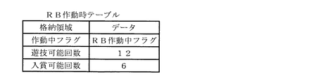
図13は、RB作動時テーブルを概念的に示す図である。   FIG. 13 is a diagram conceptually illustrating the RB operation time table.

このRB作動時テーブルは、後述するボーナス作動監視処理(図21)で用いられる。このテーブルは、データの格納領域と、この格納領域に格納されるデータとを対応づけて記憶している。同図に示すように、このテーブルでは、作動中フラグ格納領域には遊技状態を表すRB作動中フラグがデータとして対応づけられており、遊技可能回数格納領域にはRB遊技状態中に行える単位遊技数12回を表す数値、入賞可能回数格納領域にはRB遊技状態中に小役の入賞を成立させることができる回数6回を表す数値がデータとして対応づけられている。   This RB operation time table is used in bonus operation monitoring processing (FIG. 21) described later. This table stores a data storage area and data stored in the storage area in association with each other. As shown in the figure, in this table, an RB operating flag indicating a gaming state is associated with the operating flag storage area as data, and a unit game that can be performed in the RB gaming state is stored in the possible game count storage area. A numerical value representing several 12 times and a winning possible number storage area are associated with data as numerical values representing the number of times that a small role winning can be established during the RB gaming state.

図14は、BB作動時テーブルを概念的に示す図である。   FIG. 14 is a diagram conceptually illustrating the BB operation time table.

このBB作動時テーブルは、表示役がBB1またはBB2の場合に後述するボーナス作動チェック処理(図20,S21)で用いられる。このテーブルでも、データの格納領域と、この格納領域に格納されるデータとを対応づけて記憶している。同図に示すように、このテーブルでは、作動中フラグ格納領域には遊技状態を表すBB作動中フラグ、ボーナス終了枚数カウンタ格納領域にはBB遊技状態中に払い出される上限のメダル枚数350枚を表す数値がデータとして対応づけられている。   This BB operation time table is used in bonus operation check processing (FIG. 20, S21) described later when the display combination is BB1 or BB2. This table also stores the data storage area and the data stored in the storage area in association with each other. As shown in the figure, in this table, the operating flag storage area indicates the BB operating flag indicating the gaming state, and the bonus end number counter storage area indicates the upper limit of 350 medals to be paid out during the BB gaming state. Numerical values are associated as data.

次に、図15〜図19を参照して、メインCPU64が実行する遊技処理に用いられる制御RAM66の格納領域について説明する。   Next, the storage area of the control RAM 66 used for game processing executed by the main CPU 64 will be described with reference to FIGS.

図15,図16は、内部当選役1格納領域,内部当選役2格納領域を概念的に示す図である。   15 and 16 are diagrams conceptually showing the internal winning combination 1 storage area and the internal winning combination 2 storage area.

この内部当選役格納領域1,2には、図10に示す内部当選役決定テーブルを参照して内部抽選処理(図20,S8)で決定された内部当選役1,2の種別を表すデータが格納される。同図に示すように、各内部当選役格納領域1,2はビット0〜ビット7の8ビットで構成されており、各ビットにはデータ欄に示される数値がセットされる。   In the internal winning combination storage areas 1 and 2, data representing the types of the internal winning combinations 1 and 2 determined in the internal lottery process (FIG. 20, S8) with reference to the internal winning combination determination table shown in FIG. Stored. As shown in the figure, each of the internal winning combination storage areas 1 and 2 is composed of 8 bits from bit 0 to bit 7, and a numerical value shown in the data column is set to each bit.

図15に示す内部当選役1格納領域では、内部当選役1が「BB1」を表す“00000100”である場合、内部当選役1格納領域のビット0,ビット1,ビット3〜ビット7には数値“0”がセットされ、ビット2には数値“1”がセットされる。また、内部当選役1が「BB2」を表す“00000010”である場合、内部当選役1格納領域のビット0,ビット2〜ビット7には数値“0”がセットされ、ビット1には数値“1”がセットされる。また、内部当選役1が「リプレイ」を表す“00000001”である場合、内部当選役1格納領域のビット1〜ビット7には数値“0”がセットされ、ビット0には数値“1”がセットされる。   In the internal winning combination 1 storage area shown in FIG. 15, when the internal winning combination 1 is “00000100” representing “BB1”, bits 0, 1 and 1 to 3 in the internal winning combination 1 storage area are numerical values. “0” is set, and the numerical value “1” is set in bit 2. When the internal winning combination 1 is “00000010” representing “BB2”, a numerical value “0” is set in bits 0 and 2 to 7 of the internal winning combination 1 storage area, and a numerical value “0” is set in bit 1. 1 "is set. When the internal winning combination 1 is “00000001” indicating “replay”, the bit 1 to bit 7 of the internal winning combination 1 storage area is set to “0”, and the bit “0” is set to “1”. Set.

図16に示す内部当選役2格納領域では、内部当選役2が「スイカ」を表す“00000100”である場合、内部当選役2格納領域のビット0,ビット1,ビット3〜ビット7には数値“0”がセットされ、ビット2には数値“1”がセットされる。また、内部当選役1が「ベル」を表す“00000010”である場合、内部当選役2格納領域のビット0,ビット2〜ビット7には数値“0”がセットされ、ビット1には数値“1”がセットされる。また、内部当選役1が「チェリー」を表す“00000001”である場合、内部当選役2格納領域のビット1〜ビット7には数値“0”がセットされ、ビット0には数値“1”がセットされる。   In the internal winning combination 2 storage area shown in FIG. 16, when the internal winning combination 2 is “00000100” representing “watermelon”, bits 0, 1 and 1 to 3 in the internal winning combination 2 storage area are numerical values. “0” is set, and the numerical value “1” is set in bit 2. When the internal winning combination 1 is “00000010” representing “Bell”, a numerical value “0” is set in bits 0 and 2 to 7 in the internal winning combination 2 storage area, and a numerical value “0” is set in bit 1. 1 "is set. When the internal winning combination 1 is “00000001” representing “Cherry”, the numerical value “0” is set in bits 1 to 7 of the internal winning combination 2 storage area, and the numerical value “1” is set in bit 0. Set.

図17は、持越役格納領域を概念的に示す図である。   FIG. 17 is a diagram conceptually showing the carryover combination storage area.

この持越役格納領域には、内部抽選処理(図20,S8)で決定された持越役の種別を表す持越役フラグのデータが格納される。同図に示すように、持越役格納領域はビット0〜ビット7の8ビットで構成されており、各ビットにはデータ欄に示される数値がセットされる。   In this carryover combination storage area, data of a carryover combination flag representing the type of the carryover combination determined in the internal lottery process (FIG. 20, S8) is stored. As shown in the figure, the carryover combination storage area is composed of 8 bits from bit 0 to bit 7, and a numerical value shown in the data column is set in each bit.

同図に示すように、持越役フラグが「BB1」を表す“00000100”である場合、持越役格納領域のビット0,ビット1,ビット3〜ビット7には数値“0”がセットされ、ビット2には数値“1”がセットされる。また、持越役フラグが「BB2」を表す“00000010”である場合、持越役格納領域のビット0,ビット2〜ビット7には数値“0”がセットされ、ビット1には数値“1”がセットされる。また、持越役フラグがセットされていない場合には、持越役格納領域の全てのビット0〜ビット7には数値“0”がセットされる。   As shown in the figure, when the carryover combination flag is “00000100” representing “BB1”, a numerical value “0” is set in bits 0, 1 and 3 to 7 in the carryover combination storage area. The numerical value “1” is set to 2. When the carryover combination flag is “00000010” representing “BB2”, a numerical value “0” is set in bits 0 and 2 to 7 of the carryover combination storage area, and a numerical value “1” is set in bit 1. Set. When the carryover combination flag is not set, all bits 0 to 7 of the carryover combination storage area are set to a numerical value “0”.

図18は、ストップ用セレクトカウンタ格納領域を概念的に示す図である。   FIG. 18 conceptually shows the stop select counter storage area.

このストップ用セレクトカウンタ格納領域には、リール停止初期設定処理(図20,S9)において、主として内部抽選処理(図20,S8)で決定された当選番号を表すデータが、ストップ用セレクトカウンタの値として格納される。ストップ用セレクトカウンタの値が「ハズレ」に対応する当選番号0の場合、ストップ用セレクトカウンタ格納領域には数値“0”を表すデータがセットされる。ストップ用セレクトカウンタの値が「チェリー」に対応する当選番号1,「ベル」に対応する当選番号2,「スイカ」に対応する当選番号3,「リプレイ」に対応する当選番号4,「BB2」に対応する当選番号5,または「BB1」に対応する当選番号6の各場合、ストップ用セレクトカウンタ格納領域には、それぞれ数値“1”,数値“2”,数値“3”,数値“4”,数値“5”,または数値“6”を表すデータがセットされる。   In the stop select counter storage area, data representing the winning number determined mainly in the internal lottery process (FIG. 20, S8) in the reel stop initial setting process (FIG. 20, S9) is the value of the stop select counter. Stored as When the value of the stop select counter is the winning number 0 corresponding to “losing”, data representing the numerical value “0” is set in the stop select counter storage area. Winning number 1 corresponding to “Cherry”, winning number 2 corresponding to “Bell”, winning number 2 corresponding to “Watermelon”, winning number 4 corresponding to “Replay”, “BB2” In the case of each of the winning number 5 corresponding to “BB1” or the winning number 6 corresponding to “BB1”, the stop select counter storage area has a numerical value “1”, a numerical value “2”, a numerical value “3”, and a numerical value “4”, respectively. , Data “5” or data “6” is set.

また、内部抽選結果情報格納領域もこのストップ用セレクトカウンタ格納領域と同様の構成を有しているが、格納されるデータの内容は必ずしも一致しない。例えば、BB1やBB2が持ち越された場合には、内部抽選結果情報格納領域とストップ用セレクトカウンタ格納領域とでは、格納されるデータの内容がそれぞれ異なる。   The internal lottery result information storage area has the same configuration as the stop select counter storage area, but the contents of the stored data do not necessarily match. For example, when BB1 or BB2 is carried over, the contents of the stored data differ between the internal lottery result information storage area and the stop select counter storage area.

図19は、乱数値格納領域を概念的に示す図である。   FIG. 19 is a diagram conceptually illustrating a random value storage area.

この乱数値格納領域には、図20,S6の処理で抽出された乱数値が格納される。同図に示すように、乱数値格納領域には、サンプリング回路70でサンプリングされた0〜65535のうちの何れかの乱数値を表すデータがセットされる。   In this random value storage area, the random value extracted in the process of FIG. 20 and S6 is stored. As shown in the figure, in the random value storage area, data representing any random value from 0 to 65535 sampled by the sampling circuit 70 is set.

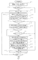
次に、図20に示すメインフローチャートを参照して、メイン制御基板61のメインCPU64の制御動作について説明する。   Next, the control operation of the main CPU 64 of the main control board 61 will be described with reference to the main flowchart shown in FIG.

初めに、メインCPU64は、遊技開始時の初期化処理を行う(図20,S1参照)。具体的には、制御RAM66の記憶内容の初期化、通信データの初期化等を行う。続いて1ゲーム終了時用初期化格納領域をセットする(S2)。   First, the main CPU 64 performs an initialization process at the start of the game (see S1, FIG. 20). Specifically, the contents stored in the control RAM 66 are initialized, the communication data is initialized, and the like. Subsequently, an initialization storage area for the end of one game is set (S2).

次に、メインCPU64は、前回のゲームに使用された制御RAM66における指定格納領域のクリア処理を行い(S3)、後述するボーナス作動監視処理を行い(S4)、後述するメダル受付・スタートチェック処理を行う(S5)。次に、メインCPU64は、乱数発生器69で発生した抽選用の乱数をサンプリング回路70によって抽出し、抽出した乱数値を乱数値格納領域(図19参照)に格納する(S6)。次に、メインCPU64は、後述する遊技状態監視処理を行い(S7)、続いて、後述する内部抽選処理を行う(S8)。   Next, the main CPU 64 clears the designated storage area in the control RAM 66 used in the previous game (S3), performs bonus operation monitoring processing described later (S4), and performs medal acceptance / start check processing described later. Perform (S5). Next, the main CPU 64 extracts the random number for lottery generated by the random number generator 69 by the sampling circuit 70, and stores the extracted random number value in the random value storage area (see FIG. 19) (S6). Next, the main CPU 64 performs a gaming state monitoring process which will be described later (S7), and subsequently performs an internal lottery process which will be described later (S8).

次に、メインCPU64は、S8の内部抽選処理での抽選結果に基づき、今回の単位遊技のリール停止制御処理(S14)で用いる停止テーブルの決定等をするリール停止初期設定処理を行う(S9)。続いて、メインCPU64は、スタートコマンドをサブ制御部通信ポート79を介してサブ制御基板62側へ送信する(S10)。「スタートコマンド」は、S7で識別した遊技状態、S8の内部抽選処理で抽選した当選役等の情報を含むコマンドである。   Next, the main CPU 64 performs a reel stop initial setting process for determining a stop table used in the reel stop control process (S14) of the current unit game based on the lottery result in the internal lottery process of S8 (S9). . Subsequently, the main CPU 64 transmits a start command to the sub control board 62 side via the sub control unit communication port 79 (S10). The “start command” is a command including information on the gaming state identified in S7, the winning combination selected in the internal lottery process in S8, and the like.

続いて、メインCPU64は、前回のリール回転開始から4.1秒が経過したか否かを判別する(S11)。この判別が“NO”のときは、4.1秒が経過するまで待ち時間消化処理(S12)が行われる。待ち時間消化処理では、遊技者のゲームを開始する操作に基づく入力を無効にする処理(ここでは、リール2〜4の回転の開始を待機させる処理)が行われる。   Subsequently, the main CPU 64 determines whether 4.1 seconds have elapsed since the start of the previous reel rotation (S11). When this determination is “NO”, waiting time digestion processing (S12) is performed until 4.1 seconds elapse. In the waiting time digestion process, a process of invalidating an input based on an operation of starting the game of the player (here, a process of waiting for the start of rotation of the reels 2 to 4) is performed.

前回のリール回転開始から4.1秒が経過すると、メインCPU64は、全リール2〜4の回転開始を要求し(S13)、全リール2〜4の回転を開始させ、続いて、後述するリール停止制御処理を行う(S14)。次に、メインCPU64は、後述する表示役検索処理を行う(S15)。   When 4.1 seconds have elapsed since the start of the previous reel rotation, the main CPU 64 requests the rotation start of all the reels 2 to 4 (S13), starts the rotation of all the reels 2 to 4, and subsequently, the reels described later. A stop control process is performed (S14). Next, the main CPU 64 performs a display combination search process described later (S15).

次に、メインCPU64は、「表示役コマンド」をサブ制御部通信ポート79を介してサブ制御基板62側へ送信する(S16)。「表示役コマンド」は、有効化入賞ライン上に実際に揃って表示されているシンボルの組合せの種類などを含んだコマンドである。次に、メインCPU64は、メダル払出処理を行う(S17)。この処理では、クレジットで遊技が行われている状態であれば、入賞によって獲得したメダル数分、貯留枚数表示部16に表示される貯留枚数が増加され、また、メダル投入口8へのメダル投入で遊技が行われている状態であれば、入賞によって獲得した枚数のメダルがメダル受皿37へ払い出される。   Next, the main CPU 64 transmits a “display combination command” to the sub control board 62 side via the sub control unit communication port 79 (S16). The “display combination command” is a command including the type of combination of symbols that are actually displayed on the activated pay line. Next, the main CPU 64 performs medal payout processing (S17). In this process, if a game is played with credit, the number of stored coins displayed on the stored coin number display unit 16 is increased by the number of medals acquired by winning, and the medal insertion into the medal insertion slot 8 is performed. If the game is being played, the number of medals won by winning is paid out to the medal tray 37.

S17の処理を行った後、メインCPU64は、メダルの払出枚数に基づいて、ボーナス終了枚数カウンタを更新する(S18)。つまり、ボーナス終了枚数カウンタが1以上であれば、メダルの払出枚数に応じて当該カウンタを減算する。次に、BB作動中フラグまたはRB作動中フラグが“オン”であるか否かを判別し(S19)、何れかのフラグが“オン”である場合には、後述するボーナス終了チェック処理を行い(S20)、何れのフラグも“オン”でない場合には、後述するボーナス作動チェック処理を行う(S21)。S20の処理の後、遊技処理はS2に戻って次の新たな単位遊技が開始される。   After performing the processing of S17, the main CPU 64 updates the bonus end number counter based on the number of medals paid out (S18). That is, if the bonus end number counter is 1 or more, the counter is subtracted according to the number of medals paid out. Next, it is determined whether or not the BB operating flag or the RB operating flag is “ON” (S19). If any of the flags is “ON”, a bonus end check process described later is performed. (S20) If none of the flags is "ON", a bonus operation check process described later is performed (S21). After the process of S20, the game process returns to S2 and the next new unit game is started.

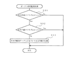
次に、図21を参照して、図20,S4で行われるボーナス作動監視処理について説明する。   Next, the bonus operation monitoring process performed in FIGS. 20 and S4 will be described with reference to FIG.

このボーナス作動監視処理では、まず、メインCPU64は、BB作動中フラグは“オン”であるか否かを判別する(図21,S31参照)。この判別が“YES”の場合、メインCPU64は、RB作動中フラグは“オン”であるか否かを判別する(S32)。この判別が“NO”の場合、メインCPU64は、RB作動時テーブルに基づいてRB作動時処理を行う(S33)。S31の判別が“NO”の場合、S32の判別が“YES”の場合、または、S33の処理を行った後、ボーナス作動監視処理は終了する。   In this bonus operation monitoring process, first, the main CPU 64 determines whether or not the BB operating flag is “ON” (see S31 in FIG. 21). If this determination is “YES”, the main CPU 64 determines whether or not the RB operating flag is “ON” (S32). If this determination is “NO”, the main CPU 64 performs RB operation processing based on the RB operation table (S33). If the determination in S31 is “NO”, the determination in S32 is “YES”, or after performing the process in S33, the bonus operation monitoring process ends.

次に、図22を参照して、図20,S5で行われるメダル受付・スタートチェック処理について説明する。   Next, with reference to FIG. 22, the medal acceptance / start check process performed in FIGS. 20 and S5 will be described.

このメダル受付・スタートチェック処理では、まず、メインCPU64は、自動投入カウンタの値は“0”であるか否か、つまり、前回の単位遊技において表示役が「リプレイ」でなく、メダルの自動投入が行われないか否かを判別する(図22,S41参照)。この判別が“YES”の場合、メインCPU64は、メダル投入口8からのメダル投入および貯留メダル投入ボタン26〜28の操作を許可するメダル投入許可処理を行う(S42)。一方、判別が“NO”の場合、メインCPU64は、自動投入カウンタに基づいて投入枚数を更新し(S43)、続いて、ベットコマンドをサブ制御部通信ポート79を介してサブ制御基板62側へ送信する(S44)。このベットコマンドは、自動投入されたメダル枚数の情報を含むコマンドである。S42またはS44の処理の後、メインCPU64は、メダル投入が許可されているか否か、つまり、メダル投入口8からのメダル投入、または、貯留メダル投入ボタン26〜28の操作が許可されているか否かを判別し(S45)、この判別が“YES”の場合、メインCPU64は、メダルセンサ8Sおよび貯留メダル投入スイッチ26S〜28Sのチェックを行う(S46)。続いて、メダルセンサ8Sでメダル投入を検出し、または、貯留メダル投入スイッチ26S〜28Sが貯留メダル投入ボタン26〜28の操作を検出したか否かを判別する(S47)。この判別が“YES”の場合、メインCPU64は、投入枚数カウンタの値に“1”を加算する(S48)。この処理において貯留メダル精算ボタン29の操作によってメダル投入口8からのメダル投入が禁止されている場合には、クレジットされているメダル枚数に検出された貯留メダル投入ボタン26〜28に応じたメダル枚数が加算される。続いて、ベットコマンドをサブ制御部通信ポート79を介してサブ制御基板62側へ送信する(S49)。このベットコマンドは、メダル投入口8からのメダル投入または貯留メダル投入ボタン26〜28の操作により単位遊技に賭けられたメダル枚数の情報を含むコマンドである。   In this medal acceptance / start check process, first, the main CPU 64 determines whether or not the value of the automatic insertion counter is “0”, that is, the display unit is not “Replay” in the previous unit game and the automatic insertion of medals. Whether or not is performed is determined (see S41 in FIG. 22). If this determination is “YES”, the main CPU 64 performs a medal insertion permission process for permitting the medal insertion from the medal insertion slot 8 and the operation of the stored medal insertion buttons 26 to 28 (S42). On the other hand, if the determination is “NO”, the main CPU 64 updates the inserted number based on the automatic insertion counter (S43), and then sends a bet command to the sub control board 62 side via the sub control unit communication port 79. Transmit (S44). This bet command is a command including information on the number of medals automatically inserted. After the processing of S42 or S44, the main CPU 64 determines whether or not the medal insertion is permitted, that is, whether or not the medal insertion from the medal insertion slot 8 or the operation of the stored medal insertion buttons 26 to 28 is permitted. (S45). If this determination is “YES”, the main CPU 64 checks the medal sensor 8S and the stored medal insertion switches 26S to 28S (S46). Subsequently, the medal insertion is detected by the medal sensor 8S, or it is determined whether or not the stored medal insertion switches 26S to 28S detect the operation of the stored medal insertion buttons 26 to 28 (S47). If this determination is “YES”, the main CPU 64 adds “1” to the value of the insertion number counter (S48). In this process, when the medal insertion from the medal insertion slot 8 is prohibited by the operation of the stored medal settlement button 29, the number of medals corresponding to the stored medal insertion buttons 26 to 28 detected in the number of credited medals. Is added. Subsequently, the bet command is transmitted to the sub control board 62 via the sub control unit communication port 79 (S49). This bet command is a command including information on the number of medals bet on a unit game by operating a medal insertion from the medal insertion slot 8 or a stored medal insertion button 26-28.

次に、メインCPU64は、RB作動中フラグはオンであるか否かを判別し(S50)、この判別が“NO”の場合には、投入枚数カウンタの値は“3”であるか否かを判別する(S51)。S50またはS51の判別が“YES”の場合、メインCPU64は、メダル投入禁止処理を行う(S52)。この処理では、投入枚数カウンタの更新が禁止されて、以降にメダルが投入された場合には、投入されたメダル枚数分だけクレジットメダル枚数が更新される。S45、S47、またはS51の判別が“NO”の場合、または、S52の処理を行った後、メインCPU64は、メダルの投入枚数、つまり、単位遊技に賭けられているメダル枚数は1枚以上であるか否かを判別し(S53)、この判別が“YES”の場合には、スタートスイッチはオンである否か、つまり、スタートレバー30の操作に基づくスタートスイッチ30Sからの入力があるか否かを判別する(S54)。S53またはS54の判別が“NO”のときは、処理はS45に戻り、上述の処理が繰り返される。一方、判別が“YES”になると、メダル受付・スタートチェック処理は終了する。   Next, the main CPU 64 determines whether or not the RB operating flag is on (S50). If this determination is “NO”, whether or not the value of the insertion number counter is “3”. Is discriminated (S51). When the determination in S50 or S51 is “YES”, the main CPU 64 performs medal insertion prohibition processing (S52). In this process, when the insertion number counter is prohibited from being updated, and medals are subsequently inserted, the number of credit medals is updated by the number of inserted medals. When the determination in S45, S47, or S51 is “NO”, or after performing the process of S52, the main CPU 64 determines that the number of medals inserted, that is, the number of medals bet on a unit game is one or more. Whether the start switch is on, that is, whether there is an input from the start switch 30S based on the operation of the start lever 30 is determined. Is determined (S54). If the determination in S53 or S54 is “NO”, the process returns to S45 and the above-described process is repeated. On the other hand, when the determination is “YES”, the medal acceptance / start check process ends.

次に、図23を参照して、図20,S7で行われる遊技状態監視処理について説明する。   Next, with reference to FIG. 23, the gaming state monitoring process performed in FIGS. 20 and S7 will be described.

この遊技状態監視処理では、まず、メインCPU64は、RB作動中フラグが“オン”であるか否かを判別する(図23,S61参照)。この判別が“YES”のとき、メインCPU64は、RB遊技状態の識別子を制御RAM64の所定領域にセットし(S62)、判別が“NO”のときは、一般遊技状態の識別子を制御RAM64の所定領域にセットする。S62またはS63の処理が行われると、遊技状態監視処理は終了する。   In this gaming state monitoring process, first, the main CPU 64 determines whether or not the RB operating flag is “ON” (see FIG. 23, S61). When this determination is “YES”, the main CPU 64 sets the identifier of the RB gaming state in a predetermined area of the control RAM 64 (S62), and when the determination is “NO”, the main CPU 64 sets the identifier of the general gaming state as a predetermined in the control RAM 64. Set to area. When the process of S62 or S63 is performed, the gaming state monitoring process ends.

次に、図24,図25を参照して、図20,S8で行われる内部抽選処理について説明する。   Next, the internal lottery process performed in FIGS. 20 and S8 will be described with reference to FIGS.

この内部抽選処理において、まず、メインCPU64は、内部抽選テーブル決定テーブル(図8)を参照して、上記のS7でセットした遊技状態に基づいて、内部抽選テーブルの種別と抽選回数を決定する(図24,S71参照)。続いて、メインCPU64は、持越役格納領域(図17)にセットされた値は“0”であるか否か、つまり、持越役がないか否かを判別し(S72)、判別が“NO”の場合には抽選回数を“4”に変更する(S73)。次に、メインCPU64は、抽選回数と同じ値を当選番号としてレジスタにセットする(S74)。従って、一般遊技状態時には“6”、RB遊技状態時には“3”、内部当選状態(持越状態)時には“4”がセットされることになる。次に、S71で決定した内部抽選テーブル(図9参照)を参照して、セットした当選番号と投入枚数カウンタの値に対応する下限値Lを取得する(S75)。続いて、制御RAM66における乱数値格納領域に格納されている乱数値Rから下限値Lを減算(R−L)する(S76)。   In this internal lottery process, first, the main CPU 64 refers to the internal lottery table determination table (FIG. 8), and determines the type of lottery table and the number of lotteries based on the gaming state set in S7 above ( (See FIG. 24, S71). Subsequently, the main CPU 64 determines whether or not the value set in the carryover combination storage area (FIG. 17) is “0”, that is, whether or not there is no carryover combination (S72). If "", the number of lotteries is changed to "4" (S73). Next, the main CPU 64 sets the same value as the number of lotteries in the register as a winning number (S74). Accordingly, “6” is set in the general gaming state, “3” is set in the RB gaming state, and “4” is set in the internal winning state (carry-over state). Next, referring to the internal lottery table determined in S71 (see FIG. 9), the lower limit L corresponding to the set winning number and the value of the inserted number counter is acquired (S75). Subsequently, the lower limit value L is subtracted (R−L) from the random number value R stored in the random number value storage area in the control RAM 66 (S76).

次に、メインCPU64は、減算の結果桁かりが行われたか否かを判別する(S77)。この判別が“NO”の場合には、下限値より乱数値の方が大きいかまたは下限値と乱数値が等しく(L≦R)、次に、S71で決定した内部抽選テーブル(図9参照)を参照して、当選番号と投入枚数カウンタに対応する上限値Uを取得する(S78)。続いて、乱数値格納領域に格納されている乱数値Rから上限値Uを減算(R−U)する(S79)。   Next, the main CPU 64 determines whether or not a digit has been obtained as a result of subtraction (S77). When this determination is “NO”, the random value is larger than the lower limit value or the lower limit value is equal to the random number value (L ≦ R), and then the internal lottery table determined in S71 (see FIG. 9). , The upper limit value U corresponding to the winning number and the inserted number counter is acquired (S78). Subsequently, the upper limit value U is subtracted (R-U) from the random value R stored in the random value storage area (S79).

次に、メインCPU64は、減算の結果得られた値が“0”であるか否かを判別する(S80)。この判別が“NO”の場合には、乱数値は上限値に等しくなく、次に、減算の結果桁かりが行われたか否かを判別する(S81)。乱数値が上限値に等しくて(R=U)S80の判別が“YES”の場合、または桁かりが行われて乱数値が上限値を下回って(R<U)S81の判別が“YES”の場合、下限値Lおよび上限値Uによって規定される数値範囲に抽出乱数値Rが属するため(L≦R≦U)、メインCPU64は、当選番号を制御RAM66の内部抽選結果情報格納領域に格納する(S82)。続いて、内部当選役決定テーブル(図10)を参照し、当選番号に基づいて内部当選役1と内部当選役2を決定する(S83)。次に、メインCPU64は、S83で決定された内部当選役2と内部当選役2格納領域(図16)との論理和を内部当選役2格納領域に格納し(S84)、内部当選役2格納領域に当選した小役の種類に応じたビットを立てる。続いて、S83で決定された内部当選役1とボーナスチェックデータ(00000110)の論理積をとり、これと持越役格納領域(図17)との論理和を持越役格納領域に格納する(S85)。これにより、決定されたBB1またはBB2が持越役格納領域に格納される。次に、メインCPU64は、内部当選役1と持越役格納領域の論理和を内部当選役1格納領域(図15)に格納し(S86)、内部当選役1格納領域に当選したボーナスまたはリプレイに応じたビットを立てる。   Next, the main CPU 64 determines whether or not the value obtained as a result of the subtraction is “0” (S80). When this determination is “NO”, the random number value is not equal to the upper limit value, and it is then determined whether or not a digit has been obtained as a result of subtraction (S81). If the random number value is equal to the upper limit value (R = U) and the determination in S80 is “YES”, or a digit is performed and the random value falls below the upper limit value (R <U), the determination in S81 is “YES”. In this case, since the extracted random number value R belongs to the numerical range defined by the lower limit value L and the upper limit value U (L ≦ R ≦ U), the main CPU 64 stores the winning number in the internal lottery result information storage area of the control RAM 66. (S82). Subsequently, with reference to the internal winning combination determination table (FIG. 10), the internal winning combination 1 and the internal winning combination 2 are determined based on the winning number (S83). Next, the main CPU 64 stores the logical sum of the internal winning combination 2 and the internal winning combination 2 storage area (FIG. 16) determined in S83 in the internal winning combination 2 storage area (S84), and stores the internal winning combination 2 storage. A bit is set according to the type of a small role won in the area. Subsequently, the logical product of the internal winning combination 1 determined in S83 and the bonus check data (00000110) is calculated, and the logical sum of this and the carryover combination storage area (FIG. 17) is stored in the carryover combination storage area (S85). . Thereby, the determined BB1 or BB2 is stored in the carryover combination storage area. Next, the main CPU 64 stores the logical sum of the internal winning combination 1 and the carryover combination storage area in the internal winning combination 1 storage area (FIG. 15) (S86), and the bonus or replay won in the internal winning combination 1 storage area. Set a bit according.

S77の判別が“YES”で乱数値Rが下限値Lを下回った場合(R<L)、S81の判別が“NO”で乱数値Rの方が上限値Uより大きい場合(U<R)、または、S86の処理の後、メインCPU64は、抽選回数を“1”減算した後(S87)、抽選回数は“0”であるか否かを判別する(S88)。この判別が“NO”の場合には、処理はS74に戻って、上述の処理が繰り返される。一方、S88の判別が“YES”で抽選回数分だけ乱数値Rと下限値L,上限値Uとの大きさが比較された場合には、メインCPU64は、内部当選役決定テーブルを参照し、当選番号“0”に基づいて内部当選役1と内部当選役2を決定する(図25,S89参照)。続いて、決定された内部当選役2と内部当選役2格納領域の論理和を内部当選役2格納領域に格納する(S90)。これにより、乱数値Rがいずれの数値範囲にも属さず、S82〜S86が行われなかった場合には、基本的に、内部当選役2格納領域にハズレがセットされる。次に、メインCPU64は、内部当選役1とボーナスチェックデータとの論理積をとり、これと持越役格納領域との論理和を持越役格納領域に格納して(S91)、ボーナスの持越役を持越役格納領域にセットする。次に、メインCPU64は、内部当選役1と持越役格納領域の論理和を内部当選役1格納領域(図15)に格納し(S92)、内部当選役1格納領域にハズレまたは持ち越されているボーナスをセットして、内部抽選処理を終了する。   If the determination in S77 is “YES” and the random number R is below the lower limit L (R <L), the determination in S81 is “NO” and the random value R is greater than the upper limit U (U <R). Alternatively, after the process of S86, the main CPU 64 subtracts “1” from the number of lotteries (S87), and determines whether the number of lotteries is “0” (S88). If this determination is “NO”, the process returns to S74 and the above-described process is repeated. On the other hand, when the determination in S88 is “YES” and the sizes of the random number R, the lower limit L, and the upper limit U are compared by the number of lotteries, the main CPU 64 refers to the internal winning combination determination table, Based on the winning number “0”, the internal winning combination 1 and the internal winning combination 2 are determined (see S89 in FIG. 25). Subsequently, the logical sum of the determined internal winning combination 2 and the internal winning combination 2 storage area is stored in the internal winning combination 2 storage area (S90). As a result, when the random number R does not belong to any numerical value range and S82 to S86 are not performed, basically, the loss is set in the internal winning combination 2 storage area. Next, the main CPU 64 calculates the logical product of the internal winning combination 1 and the bonus check data, stores the logical sum of this and the carryover combination storage area in the carryover combination storage area (S91), and determines the bonus carryover combination. Set in the carryover combination storage area. Next, the main CPU 64 stores the logical sum of the internal winning combination 1 and the carryover combination storage area in the internal winning combination 1 storage area (FIG. 15) (S92), and is lost or carried over to the internal winning combination 1 storage area. A bonus is set and the internal lottery process is terminated.

次に、図26を参照して、図20,S9で行われるリール停止初期設定処理について説明する。   Next, the reel stop initial setting process performed in FIGS. 20 and S9 will be described with reference to FIG.

このリール停止初期設定処理において、まず、メインCPU64は、内部抽選結果情報格納領域にセットされている値は“0”であるか、つまり、内部当選役がハズレであるか否かを判別する(図26,S101参照)。この判別が“YES”である場合には、次に、メインCPU64は、持越役格納領域(図17)にセットされている値は“0”であるか、つまり、持ち越されているボーナスがあるか否かを判別する(S102)。内部当選役がハズレでなくてS101の判別が“NO”の場合、または、内部当選役がハズレで持ち越されているボーナスがなくてS102の判別が“YES”の場合、メインCPU64は、確率抽選処理(図20,S8)で決定された当選番号をストップ用セレクトカウンタに格納する(S103)。内部当選役がハズレで持ち越されているボーナスがあってS102の判別が“NO”の場合、メインCPU64は、持越役格納領域のデータを番号化し、“3”を加算して、得られた値をストップ用セレクトカウンタに格納する(S104)。つまり、持越役格納領域のビット0がオンの場合には1、ビット1がオンの場合には2、ビット2がオンの場合には3と番号化し、番号化したこの値に3を加え、ビット0がオンの場合には4(リプレイ)、ビット1がオンの場合には5(BB2)、ビット3がオンの場合には6(BB1)と整数化した値をストップ用セレクトカウンタに格納する。S103またはS104の処理の後、メインCPU64は、停止テーブル決定テーブル(図11)を参照して、ストップ用セレクトカウンタに格納した当選番号に基づいて停止テーブルを決定し、決定した停止テーブルを制御RAM66の所定領域に格納し(S105)、リール停止初期設定処理を終了する。   In this reel stop initial setting process, first, the main CPU 64 determines whether or not the value set in the internal lottery result information storage area is “0”, that is, whether or not the internal winning combination is lost ( (See FIG. 26, S101). If this determination is “YES”, then the main CPU 64 determines whether the value set in the carryover combination storage area (FIG. 17) is “0”, that is, there is a bonus carried over. Is determined (S102). If the internal winning combination is not lost and the determination in S101 is “NO”, or if there is no bonus that the internal winning combination is lost and carried over and the determination in S102 is “YES”, the main CPU 64 determines the probability lottery. The winning number determined in the process (FIG. 20, S8) is stored in the stop select counter (S103). If there is a bonus that the internal winning combination is lost and carried over and the determination in S102 is “NO”, the main CPU 64 numbers the data in the carryover combination storage area, adds “3”, and the value obtained Is stored in the stop select counter (S104). That is, it is numbered 1 when bit 0 of the carryover combination storage area is on, 2 when bit 1 is on, 3 when bit 2 is on, and adds 3 to this numbered value. When bit 0 is on, 4 (replay), 5 (BB2) when bit 1 is on, and 6 (BB1) when bit 3 is on are stored in the stop select counter. To do. After the processing of S103 or S104, the main CPU 64 refers to the stop table determination table (FIG. 11), determines the stop table based on the winning number stored in the stop select counter, and determines the determined stop table in the control RAM 66. (S105), and the reel stop initial setting process is terminated.

次に、図27を参照して、図20,S14で行われるリール停止制御処理について説明する。   Next, the reel stop control process performed in FIGS. 20 and S14 will be described with reference to FIG.

このリール停止制御処理において、まず、メインCPU64は、リール2〜4の回転が定速になっていずれかの停止ボタン31〜33が押圧操作され、有効なストップスイッチが“オン”されたか否かを判別する(図27,S111参照)。この判別が“NO”である場合には、次に、メインCPU64は、停止ボタン31〜33が操作されずに自動停止タイマの値が“0”となったか否かを判別する(S112)。この判別が“NO”である場合には、処理はS111に戻り、上述の処理が繰り返される。一方、自動停止タイマの値が“0”になってS112の判別が“YES”である場合には、メインCPU64は、停止制御対象としてより左側のリール2〜4の情報を取得する(S113)。有効なストップスイッチが“オン”されてS111の判別が“YES”の場合、または、S113の処理を終えると、続いて、リール停止初期設定処理(図20,S9)で決定された停止テーブルと、内部抽選処理(図20,S8)で決定された内部当選役1,2と、引込優先順位テーブル(図12)に基づいて滑りコマ数を決定する(S114)。次に、メインCPU64は、S114で決定された滑りコマ数と現在のシンボル位置に基づいて、シンボルの停止予定位置を決定し(S115)、決定した停止予定位置にシンボルが移動してくるのを待つ停止予定位置待ち状態に処理を移行する(S116)。次に、メインCPU64は、リール停止コマンドをサブ制御部通信ポート79を介してサブ制御基板62側へ送信し(S117)、続いて、現在回転中のリール2〜4は有るか否かを判別し(S118)、この判別が“YES”のときには、処理はS111に戻って上述の処理が繰り返される。一方、判別が“NO”のときには、停止制御処理を終了する。   In this reel stop control process, first, the main CPU 64 determines whether or not any stop button 31 to 33 is pressed by rotating the reels 2 to 4 at a constant speed and an effective stop switch is turned “ON”. Is discriminated (see FIG. 27, S111). If this determination is “NO”, then the main CPU 64 determines whether or not the value of the automatic stop timer has become “0” without operating the stop buttons 31 to 33 (S112). If this determination is “NO”, the processing returns to S111 and the above-described processing is repeated. On the other hand, when the value of the automatic stop timer becomes “0” and the determination in S112 is “YES”, the main CPU 64 acquires information on the left reels 2 to 4 as a stop control target (S113). . When the effective stop switch is “ON” and the determination in S111 is “YES”, or when the processing of S113 is completed, the stop table determined in the reel stop initial setting processing (FIG. 20, S9) The number of sliding symbols is determined based on the internal winning combinations 1 and 2 determined in the internal lottery process (FIG. 20, S8) and the drawing priority table (FIG. 12) (S114). Next, the main CPU 64 determines the planned stop position of the symbol based on the number of sliding symbols determined in S114 and the current symbol position (S115), and the symbol moves to the determined planned stop position. The process shifts to a waiting stop position waiting state (S116). Next, the main CPU 64 transmits a reel stop command to the sub control board 62 side via the sub control unit communication port 79 (S117), and then determines whether or not there are any reels 2 to 4 that are currently rotating. (S118) If this determination is “YES”, the process returns to S111 and the above-described processes are repeated. On the other hand, when the determination is “NO”, the stop control process is terminated.

次に、図28を参照して、図20,S15で行われる表示役検索処理について説明する。   Next, with reference to FIG. 28, the display combination retrieval process performed in FIGS. 20 and S15 will be described.

この表示役検索処理において、まず、メインCPU64は、シンボル格納領域の先頭アドレスを取得する(図28,S121参照)。シンボル格納領域の各アドレスには、各入賞ラインL1,L2A,L2B,L3A,L3Bに揃えられているシンボル組合せがセットされている。続いて、メインCPU64は、有効ラインカウンタの値は“0”であるか否かを判別する(S122)。この判別が“NO”である場合には、当該アドレスに格納されているシンボルの組合せと、シンボル組合せテーブル(図7)に基づいて、表示役と払出枚数を特定する(S123)。続いて、有効ラインカウンタの値を“1”減算する(S124)と共に、シンボル格納領域の次のアドレスを取得する。その後、処理はS122に戻って上述の処理が繰り返され、有効化入賞ライン1本毎に表示役に対応するシンボル組合せが揃っているか否かが判別される。S122の判別が“YES”になると、全ての有効化入賞ラインについて表示役と払出枚数が特定されるので、表示役検索処理は終了する。また、表示役検索処理では、特定された表示役と内部当選役とが異なる場合、または、表示役が表示役判定データに含まれない場合には、配当枚数表示部20および液晶表示装置22にイリーガルエラーが表示される。   In this display combination retrieval process, first, the main CPU 64 obtains the leading address of the symbol storage area (see S121 in FIG. 28). At each address in the symbol storage area, a symbol combination aligned with each winning line L1, L2A, L2B, L3A, L3B is set. Subsequently, the main CPU 64 determines whether or not the value of the effective line counter is “0” (S122). If this determination is “NO”, the display combination and the number of payouts are specified based on the symbol combination stored in the address and the symbol combination table (FIG. 7) (S123). Subsequently, “1” is subtracted from the value of the effective line counter (S124), and the next address of the symbol storage area is acquired. Thereafter, the processing returns to S122 and the above-described processing is repeated, and it is determined whether or not there is a symbol combination corresponding to the display combination for each activated pay line. When the determination in S122 is “YES”, the display combination and the number of payouts are specified for all the activated pay lines, and thus the display combination search process ends. In the display combination search process, when the specified display combination is different from the internal winning combination, or when the display combination is not included in the display combination determination data, the payout number display unit 20 and the liquid crystal display device 22 are displayed. An illegal error is displayed.

次に、図29を参照して、図20,S20で行われるボーナス終了チェック処理について説明する。   Next, with reference to FIG. 29, the bonus end check process performed in FIG. 20 and S20 will be described.

このボーナス終了チェック処理において、まず、メインCPU64は、RB作動中フラグは“オン”であるか否かを判別する(図29,S131参照)。この判別が“NO”である場合には、メインCPU64は、BB遊技状態中に払出可能なメダル枚数350枚をカウントするボーナス終了枚数カウンタ(図14参照)の値は“0”であるか否かを判別する(S132)。S131の判別が“YES”の場合、メインCPU64は、小役の入賞が成立したか否か、つまり、図20,S15の表示役検索処理で表示役として小役が特定されたか否かを判別する(S133)。この判別が“YES”である場合には、メインCPU64は、上記のボーナス終了枚数カウンタの値は“0”であるか否かを判別し(S134)、この判別が“YES”である場合は、RB作動中フラグや入賞可能回数および遊技可能回数をクリアする等のRB終了時処理を行う(S135)。S132の判別が“YES”の場合、または、S135の処理を行った後、メインCPU64は、BB作動中フラグやボーナス終了枚数カウンタをクリアする等のBB終了時処理を行う(S136)。   In the bonus end check process, first, the main CPU 64 determines whether or not the RB operating flag is “ON” (see S131 in FIG. 29). When this determination is “NO”, the main CPU 64 determines whether the value of the bonus end number counter (see FIG. 14) for counting 350 medals that can be paid out during the BB gaming state is “0”. Is determined (S132). When the determination in S131 is “YES”, the main CPU 64 determines whether or not a small combination winning is established, that is, whether or not a small combination is specified as a display combination in the display combination search process of FIG. (S133). If this determination is “YES”, the main CPU 64 determines whether or not the value of the bonus end number counter is “0” (S134), and if this determination is “YES”. RB end processing such as clearing the RB operating flag, the number of possible winnings and the number of possible games is performed (S135). If the determination in S132 is “YES”, or after performing the process of S135, the main CPU 64 performs a BB end time process such as clearing the BB operating flag and the bonus end number counter (S136).

S134の判別が“NO”である場合、メインCPU64は、入賞可能回数を“1”減算し(S137)、続いて、入賞可能回数は“0”であるか否かを判別する(S138)。この判別が“NO”の場合、または、S133の判別が“NO”の場合、メインCPU64は、遊技可能回数を“1”減算し(S139)、続いて、遊技可能回数は“0”であるか否かを判別する(S140)。この判別またはS138の判別が“YES”の場合、メインCPU64は、上記のRB終了時処理を行う(S141)。S132またはS140の判別が“NO”の場合、または、S136もしくはS141の処理を行った後、ボーナス終了チェック処理を終了する。   When the determination in S134 is “NO”, the main CPU 64 subtracts “1” from the number of possible winnings (S137), and then determines whether or not the number of possible winnings is “0” (S138). If this determination is “NO”, or if the determination in S133 is “NO”, the main CPU 64 subtracts “1” from the possible number of games (S139), and then the possible number of games is “0”. Whether or not (S140). When this determination or the determination in S138 is “YES”, the main CPU 64 performs the above-described RB end process (S141). If the determination in S132 or S140 is “NO”, or after performing the process of S136 or S141, the bonus end check process is terminated.

次に、図30を参照して、図20,S21で行われるボーナス作動チェック処理について説明する。   Next, with reference to FIG. 30, the bonus operation check process performed in FIGS. 20 and S21 will be described.

このボーナス作動チェック処理では、まず、メインCPU64は、リール2〜4に実際に揃って表示されている表示役は「リプレイ」であるか否かを判別する(図30,S151参照)。この判別が“YES”である場合には、投入枚数を自動投入カウンタに複写する(S152)。つまり、その単位遊技に賭けられていた枚数と同数のメダルを表す数値データを自動投入カウンタの値にセットする。   In this bonus operation check process, first, the main CPU 64 determines whether or not the display combination actually displayed on the reels 2 to 4 is “replay” (see FIG. 30, S151). If this determination is “YES”, the number of inserted sheets is copied to the automatic loading counter (S152). That is, numerical data representing the same number of medals as the number bet on the unit game is set to the value of the automatic insertion counter.

S151の判別が“NO”の場合、メインCPU64は、表示役は「BB1」または「BB2」であるか否かを判別する(S153)。この判別が“YES”の場合、メインCPU64は、ボーナス作動時テーブルに基づいてBB作動時処理を行い(S154)、続いて、持越役をクリアする(S155)。BB作動時処理では、メインCPU64は、BB作動中フラグをセットすると共にボーナス終了枚数カウンタに350をセットする。S153の判別が“NO”である場合、または、S152若しくはS155の処理が行われた後、ボーナス作動チェック処理は終了する。   When the determination in S151 is “NO”, the main CPU 64 determines whether or not the display combination is “BB1” or “BB2” (S153). When this determination is “YES”, the main CPU 64 performs the BB operation process based on the bonus operation table (S154), and then clears the carryover combination (S155). In the BB operation process, the main CPU 64 sets a BB operation flag and sets 350 in the bonus end number counter. If the determination in S153 is “NO”, or after the processing in S152 or S155 is performed, the bonus operation check processing is terminated.

本実施形態によるパチスロ機1では、上述のように、図9(a)に示す一般遊技状態用内部抽選テーブルにおいて、「チェリー」の小役に対応する当選番号1には、投入枚数3枚の場合に下限値0,上限値599の数値範囲が割り当てられており、「BB2」に対応する当選番号5には、投入枚数3枚の場合には当選番号1の場合と一部重複する下限値579,上限値661の数値範囲が割り当てられている。また、「スイカ」の小役に対応する当選番号3には、投入枚数3枚の場合には下限値1785,上限値2184の数値範囲が割り当てられており、「BB1」に対応する当選番号6には、投入枚数3枚の場合には当選番号3の場合と一部重複する下限値1730,上限値1812の数値範囲が割り当てられている。   In the pachislot machine 1 according to the present embodiment, as described above, in the internal lottery table for the general gaming state shown in FIG. 9A, the winning number 1 corresponding to the small part of “Cherry” In this case, the numerical range of the lower limit value 0 and the upper limit value 599 is assigned, and the winning number 5 corresponding to “BB2” has a lower limit value that partially overlaps with the winning number 1 in the case of 3 sheets. A numerical value range of 579 and an upper limit value 661 is assigned. In addition, the winning number 3 corresponding to the small part of “watermelon” is assigned a numerical range of a lower limit value 1785 and an upper limit value 2184 in the case of 3 inserted sheets, and the winning number 6 corresponding to “BB1” is assigned. In the case of three inserted sheets, a numerical range of a lower limit value 1730 and an upper limit value 1812 that are partially overlapped with the case of the winning number 3 is assigned.

本実施形態によるパチスロ機1によれば、このように、ある当選役である「チェリー」または「スイカ」の小役に応じた数値範囲と、「チェリー」または「スイカ」の小役とは異なる他の当選役である「BB1」または「BB2」に応じた数値範囲とが、少なくとも一部において重複して規定されているので、乱数抽出手段により抽出された乱数がこの重複した数値範囲に属すると、各数値範囲に応じたある当選役と他の当選役との複数の当選役であるチェリーとBB2、またはスイカとBB1が同時に決定される。このため、1つの乱数値および1つの内部抽選テーブルのみを用いて、一度に複数の当選役を決定することが可能な新たな当選役の抽選方式を提供することができる。また、内部抽選テーブルを複数設ける必要がないので、プログラムROM65のメモリ容量を増やすようなハードウエア資源を増加させる必要もない。   According to the pachislot machine 1 according to the present embodiment, the numerical range corresponding to the small role of “Cherry” or “Watermelon” that is a winning combination is different from the small role of “Cherry” or “Watermelon” as described above. Since the numerical range corresponding to “BB1” or “BB2” which is another winning combination is defined at least in part, the random numbers extracted by the random number extraction means belong to this overlapping numerical range Then, cherry and BB2, or watermelon and BB1, which are a plurality of winning combinations of a winning combination and another winning combination corresponding to each numerical range, are determined simultaneously. Therefore, it is possible to provide a new winning combination lottery system capable of determining a plurality of winning combinations at a time using only one random value and one internal lottery table. In addition, since it is not necessary to provide a plurality of internal lottery tables, it is not necessary to increase hardware resources that increase the memory capacity of the program ROM 65.

また、各当選役に割り当てられる数値範囲は、図9に示すように下限値および上限値をもって定められるため、必ずしも順に設ける必要がなく、各数値範囲を重複させたり分散させて不規則に設けることが可能となる。このため、不正行為により一定のタイミングでスタートレバー30による開始操作が繰り返されても、抽出乱数値が入賞に係る当選役に応じた数値範囲に入り続けることはなくなる。よって、本来予定されている確率以上に入賞に係る当選役が決定され続けるといったことはなくなり、パチスロ機1を設置する遊技店の経営を悪化させてしまうことがなくなる。   In addition, the numerical range assigned to each winning combination is determined by a lower limit value and an upper limit value as shown in FIG. 9, so it is not always necessary to provide them in order. Is possible. For this reason, even if the start operation by the start lever 30 is repeated at a certain timing due to fraud, the extracted random number value does not continue to be in the numerical value range corresponding to the winning combination related to winning. Therefore, the winning combination relating to the winning is not determined more than the originally scheduled probability, and the management of the amusement shop in which the pachislot machine 1 is installed is not deteriorated.

この結果、当選役の新たな抽選方式をもたらすことにより遊技者の固定概念を打破して新たな面白味を生じさせると共に、不正行為への有効な対策を講じることが可能で、遊技者および遊技店の双方の要請を満足させることができるパチスロ機1を提供することが可能となる。   As a result, by introducing a new lottery system for winning roles, it is possible to break down the fixed concept of players and create new fun, and to take effective measures against fraudulent acts. It is possible to provide a pachislot machine 1 that can satisfy both of the requirements.

また、本実施形態によるパチスロ機1によれば、内部抽選処理(図20,S8)において、「チェリー」の小役と「BB2」、または、「スイカ」の小役と「BB1」が同時に内部当選役として決定されることがあるので、「チェリー」の小役または「スイカ」の小役の入賞が成立した場合には、その単位遊技において、「BB2」または「BB1」も内部当選役として決定されたのではないかという期待感を持たせることができる。   In addition, according to the pachislot machine 1 according to the present embodiment, in the internal lottery process (FIG. 20, S8), the small part of “Cherry” and “BB2” or the small part of “Watermelon” and “BB1” are simultaneously Since the winning combination of “Cherry” or “Watermelon” is established, “BB2” or “BB1” may be used as an internal winning combination in the unit game. It can give a sense of expectation that it has been decided.

また、本実施形態によるパチスロ機1によれば、当選役として決定された例えば「BB2」が持越手段により持ち越された場合には、持ち越された当選役にも基づき、シンボルの変動表示が停止制御される。このため、複数の当選役例えば「チェリー」および「BB2」が決定された場合に、一方の当選役「チェリー」に応じたシンボルの変動表示の停止制御のみが行われて、遊技者が他方の当選役「BB2」に応じたシンボルの変動表示の停止制御を享受できなくなり、不利益を被る事態を防ぐことができる。   Further, according to the pachislot machine 1 according to the present embodiment, when, for example, “BB2” determined as the winning combination is carried over by the carryover means, the symbol variable display is controlled to stop based on the carried-over winning combination. Is done. Therefore, when a plurality of winning combinations such as “Cherry” and “BB2” are determined, only the symbol variable display stop control according to one winning combination “Cherry” is performed, and the player It becomes impossible to enjoy the symbol variable display stop control according to the winning combination “BB2”, thereby preventing a disadvantage.

なお、上記実施形態の説明では、「チェリー」の小役と「BB2」、および、「スイカ」の小役と「BB1」とで、割り当てられた乱数範囲が一部重複する場合について説明した。しかし、割り当てられた乱数範囲が一部重複する役の種別は任意であり、適宜変更して差し支えない。   In the description of the above-described embodiment, the case where the assigned random number ranges partially overlap with the “Cherry” small role and “BB2”, and the “Watermelon” small role and “BB1” has been described. However, the types of the combinations in which the assigned random number ranges partially overlap are arbitrary and may be changed as appropriate.

また、上記実施の形態の説明では、内部抽選処理(図20,S8)において、乱数値Rが数値範囲の下限値Lまたは上限値Uと等しい(R=LまたはR=U)場合にもその数値範囲が割り当てられた当選役を内部当選役として決定した。しかし、乱数値Rが数値範囲の下限値Lを上回り(L<R)、かつ、上限値を下回った(R<U)場合にのみ、その数値範囲が割り当てられた当選役を内部当選役として決定し、乱数値Rが数値範囲の下限値または上限値と等しい(R=LまたはR=U)場合には、乱数値Rが数値範囲に属しないと判別して、その数値範囲が割り当てられた当選役が内部当選役として決定されない構成としてもよい。   In the description of the above embodiment, even when the random value R is equal to the lower limit value L or the upper limit value U of the numerical range (R = L or R = U) in the internal lottery process (FIG. 20, S8) The winning combination assigned with the numerical range is determined as the internal winning combination. However, only when the random value R exceeds the lower limit L of the numerical range (L <R) and falls below the upper limit (R <U), the winning combination to which the numerical range is assigned is determined as an internal winning combination. When the random number R is equal to the lower limit value or upper limit value of the numerical range (R = L or R = U), it is determined that the random value R does not belong to the numerical range, and the numerical range is assigned. The winning combination may not be determined as an internal winning combination.

上記実施形態においては、本発明による遊技機をパチスロ機1に適用した場合について説明したが、遊技者による開始操作の検出に基づいて複数の役の中から内部当選役を決定する他の遊技機に本発明を適用することも可能である。このような遊技機に本発明を適用した場合においても上記実施形態と同様な作用効果が奏される。   In the above embodiment, the case where the gaming machine according to the present invention is applied to the pachislot machine 1 has been described. However, other gaming machines that determine an internal winning combination from a plurality of combinations based on detection of a start operation by the player The present invention can also be applied to. Even when the present invention is applied to such a gaming machine, the same effects as the above-described embodiment can be obtained.

本発明の一実施形態によるパチスロ機の外観を示す正面図である。It is a front view which shows the external appearance of the pachislot machine by one Embodiment of this invention. 本発明の一実施形態によるパチスロ機を構成するリールユニットの外観を示す斜視図である。It is a perspective view showing the appearance of the reel unit which constitutes the pachi-slot machine by one embodiment of the present invention. 図2に示すリールユニットを構成する各リールの構成を示す分解斜視図である。It is a disassembled perspective view which shows the structure of each reel which comprises the reel unit shown in FIG. 図3に示すリールの外周部に描かれたシンボル列を示す図である。It is a figure which shows the symbol row drawn on the outer peripheral part of the reel shown in FIG. 本発明の一実施形態によるパチスロ機のメイン制御基板に構成された回路構成を示すブロック図である。It is a block diagram which shows the circuit structure comprised by the main control board of the pachislot machine by one Embodiment of this invention. 本発明の一実施形態によるパチスロ機のサブ制御基板に構成された回路構成を示すブロック図である。It is a block diagram which shows the circuit structure comprised by the sub control board of the pachislot machine by one Embodiment of this invention. 本発明の一実施形態に用いられるシンボル組合せテーブルを概念的に示す図である。It is a figure which shows notionally the symbol combination table used for one Embodiment of this invention. 本発明の一実施形態に用いられる内部抽選テーブル決定テーブルを概念的に示す図である。It is a figure which shows notionally the internal lottery table determination table used for one Embodiment of this invention. 本発明の一実施形態に用いられる内部抽選テーブルを概念的に示す図である。It is a figure which shows notionally the internal lottery table used for one Embodiment of this invention. 本発明の一実施形態に用いられる内部当選役決定テーブルを概念的に示す図である。It is a figure which shows notionally the internal winning combination determination table used for one Embodiment of this invention. 本発明の一実施形態に用いられる停止テーブル決定テーブルを概念的に示す図である。It is a figure which shows notionally the stop table determination table used for one Embodiment of this invention. 本発明の一実施形態に用いられる引込優先順位テーブルを概念的に示す図である。It is a figure which shows notionally the drawing priority order table used for one Embodiment of this invention. 本発明の一実施形態に用いられるRB作動時テーブルを概念的に示す図である。It is a figure which shows notionally the table at the time of RB operation | movement used for one Embodiment of this invention. 本発明の一実施形態に用いられるBB作動時テーブルを概念的に示す図である。It is a figure which shows notionally the table at the time of BB operation | movement used for one Embodiment of this invention. 本発明の一実施形態に用いられる内部当選役1格納領域を概念的に示す図である。It is a figure which shows notionally the internal winning combination 1 storage area used for one Embodiment of this invention. 本発明の一実施形態に用いられる内部当選役2格納領域を概念的に示す図である。It is a figure which shows notionally the internal winning combination 2 storage area | region used for one Embodiment of this invention. 本発明の一実施形態に用いられる持越役格納領域を概念的に示す図である。It is a figure which shows notionally the carryover combination storage area used for one Embodiment of this invention. 本発明の一実施形態に用いられるストップ用セレクトカウンタ格納領域を概念的に示す図である。It is a figure which shows notionally the select counter storage area for a stop used for one Embodiment of this invention. 本発明の一実施形態に用いられる乱数値格納領域を概念的に示す図である。It is a figure which shows notionally the random value storage area used for one Embodiment of this invention. 本発明の一実施形態によるパチスロ機のメインCPUによる遊技処理の概略を示すフローチャートである。It is a flowchart which shows the outline of the game processing by main CPU of the pachi-slot machine by one Embodiment of this invention. 図20に示すボーナス作動監視処理の概略を示すフローチャートである。It is a flowchart which shows the outline of the bonus operation | movement monitoring process shown in FIG. 図20に示すメダル受付・スタートチェック処理の概略を示すフローチャートである。21 is a flowchart showing an outline of medal acceptance / start check processing shown in FIG. 20. 図20に示す遊技状態監視処理の概略を示すフローチャートである。It is a flowchart which shows the outline of the gaming state monitoring process shown in FIG. 図20に示す内部抽選処理の概略を示す第1のフローチャートである。It is a 1st flowchart which shows the outline of the internal lottery process shown in FIG. 図20に示す内部抽選処理の概略を示す第2のフローチャートである。FIG. 21 is a second flowchart showing an outline of the internal lottery process shown in FIG. 20. FIG. 図20に示すリール停止初期設定処理の概略を示すフローチャートである。FIG. 21 is a flowchart showing an outline of a reel stop initial setting process shown in FIG. 20. FIG. 図20に示すリール停止制御処理の概略を示すフローチャートである。FIG. 21 is a flowchart showing an outline of a reel stop control process shown in FIG. 20. FIG. 図20に示す表示役検索処理の概略を示すフローチャートである。FIG. 21 is a flowchart showing an outline of a display combination search process shown in FIG. 20. FIG. 図20に示すボーナス終了チェック処理の概略を示すフローチャートである。FIG. 21 is a flowchart showing an outline of bonus end check processing shown in FIG. 20. FIG. 図20に示すボーナス作動チェック処理の概略を示すフローチャートである。It is a flowchart which shows the outline of the bonus action check process shown in FIG.

符号の説明Explanation of symbols

1…パチスロ機
2〜4…リール
8…メダル投入口
8S…投入メダルセンサ
22…液晶表示装置
29…貯留メダル精算ボタン
29S…貯留メダル精算スイッチ
30…スタートレバー
30S…スタートスイッチ
61…メイン制御基板
62…サブ制御基板
63,81…マイコン(マイクロコンピュータ)
64…メインCPU(中央演算処理装置)
82…サブCPU
65,83…プログラムROM(リード・オンリ・メモリ)
66,84…制御RAM(ランダム・アクセス・メモリ)
90…VDP(ビデオディスプレイプロセッサ)
DESCRIPTION OF SYMBOLS 1 ... Pachi slot machine 2-4 ... Reel 8 ... Medal insertion slot 8S ... Insertion medal sensor 22 ... Liquid crystal display device 29 ... Storage medal adjustment button 29S ... Storage medal adjustment switch 30 ... Start lever 30S ... Start switch 61 ... Main control board 62 ... Sub-control board 63, 81 ... Microcomputer
64 ... main CPU (central processing unit)
82 ... Sub CPU
65, 83 ... Program ROM (read-only memory)
66, 84 ... Control RAM (Random Access Memory)
90 ... VDP (Video Display Processor)

Claims (2)

複数の図柄を表示する図柄表示手段と、遊技者による開始操作の検出を行う開始操作検出手段と、この開始操作検出手段により行われる開始操作の検出に基づいて所定の乱数範囲の中から乱数を抽出する乱数抽出手段と、前記所定の乱数範囲に含まれる数値範囲の下限値および上限値を当選役に応じて規定する抽選値規定手段と、前記乱数抽出手段により抽出された乱数の値を前記下限値と前記上限値との双方と比較して前記乱数抽出手段により抽出された乱数が前記数値範囲に属するか否かを判別する乱数値判別手段と、この乱数値判別手段により前記乱数抽出手段により抽出された乱数が前記数値範囲に属すると判別された場合にはその数値範囲に応じた当選役を決定する当選役決定手段と、前記開始操作検出手段により行われる開始操作の検出に基づいて前記図柄表示手段により表示される図柄の変動を行う図柄変動手段と、遊技者による停止操作の検出を行う停止操作検出手段と、この停止操作検出手段により行われる停止操作の検出と前記当選役決定手段により決定される当選役とに基づき前記図柄変動手段により行われる図柄の変動の停止制御を行う停止制御手段と、この停止制御手段による停止制御の結果前記図柄表示手段により予め定められた図柄組合せが停止表示されると遊技価値を付与する遊技価値付与手段とを備え、
前記抽選値規定手段は、ある当選役に応じた前記数値範囲と前記ある当選役とは異なる他の当選役に応じた前記数値範囲とを少なくとも一部において重複させていることを特徴とする遊技機。
A symbol display means for displaying a plurality of symbols, a start operation detecting means for detecting a start operation by the player, and a random number from a predetermined random number range based on the detection of the start operation performed by the start operation detecting means. A random number extracting means for extracting; a lottery value defining means for defining a lower limit value and an upper limit value of a numerical value range included in the predetermined random number range according to a winning combination; and a random number value extracted by the random number extracting means Random value discriminating means for discriminating whether or not the random number extracted by the random number extracting means belongs to the numerical range in comparison with both the lower limit value and the upper limit value, and the random number extracting means by the random value discriminating means A winning combination determining means for determining a winning combination corresponding to the numerical range when it is determined that the random number extracted by the numerical value range belongs to the numerical value range; and a start operation performed by the start operation detecting means. The symbol change means for changing the symbol displayed by the symbol display means based on the detection of the game, the stop operation detection means for detecting the stop operation by the player, and the detection of the stop operation performed by the stop operation detection means And a winning control determined by the winning combination determining means, stop control means for performing stop control of symbol variation performed by the symbol varying means, and a result of stop control by the stop control means in advance by the symbol display means. A game value giving means for giving a game value when a predetermined symbol combination is stopped and displayed;
The lottery value defining means at least partially overlaps the numerical range according to a winning combination and the numerical range according to another winning combination different from the certain winning combination. Machine.
前記当選役決定手段により当選役として決定された前記ある当選役および前記他の当選役に対応するいずれかの図柄組合せが前記図柄表示手段により停止表示されない場合には、停止表示されない当選役に対応する図柄組合せが前記図柄表示手段により停止表示されるまでその当選役に関する情報を持ち越す持越手段を備え、
前記停止制御手段は、前記持越手段により持ち越された当選役にも基づき、前記図柄表示手段による図柄の変動表示を停止制御することを特徴とする請求項1に記載の遊技機。
Corresponds to a winning combination that is not stopped and displayed when any symbol combination corresponding to the one winning combination and the other winning combination determined by the winning combination determining means is not stopped by the symbol display means. A carry-over means for carrying over information on the winning combination until the symbol combination to be stopped and displayed by the symbol display means;
2. The gaming machine according to claim 1, wherein the stop control means controls to stop the display of the symbol change by the symbol display means based on the winning combination carried over by the carry-over means.
JP2005157188A 2005-05-30 2005-05-30 Game machine Pending JP2006326160A (en)

Priority Applications (1)

Application Number Priority Date Filing Date Title
JP2005157188A JP2006326160A (en) 2005-05-30 2005-05-30 Game machine

Applications Claiming Priority (1)

Application Number Priority Date Filing Date Title
JP2005157188A JP2006326160A (en) 2005-05-30 2005-05-30 Game machine

Publications (2)

Publication Number Publication Date
JP2006326160A true JP2006326160A (en) 2006-12-07
JP2006326160A5 JP2006326160A5 (en) 2009-01-29

Family

ID=37548482

Family Applications (1)

Application Number Title Priority Date Filing Date
JP2005157188A Pending JP2006326160A (en) 2005-05-30 2005-05-30 Game machine

Country Status (1)

Country Link
JP (1) JP2006326160A (en)

Cited By (3)

* Cited by examiner, † Cited by third party
Publication number Priority date Publication date Assignee Title
JP2008289688A (en) * 2007-05-25 2008-12-04 Daikoku Denki Co Ltd Slot machine
JP2008302026A (en) * 2007-06-07 2008-12-18 Aruze Corp Game machine
JP2008302032A (en) * 2007-06-07 2008-12-18 Aruze Corp Game machine

Similar Documents

Publication Publication Date Title
JP2006204627A (en) Game machine
JP2006204626A (en) Game machine
JP2007143939A (en) Game machine
JP2008006143A (en) Game machine
JP2006204624A (en) Game machine
JP2006204625A (en) Game machine
JP4535891B2 (en) Game machine
JP2007007133A (en) Game machine
JP2007117258A (en) Game machine
JP2006326160A (en) Game machine
JP2007117357A (en) Game machine
JP4606962B2 (en) Game machine
JPH11309242A (en) Game machine
JP2008006142A (en) Game machine
JP2006326164A (en) Game machine
JP4674691B2 (en) Game machine
JP2008029388A (en) Game machine
JP4955937B2 (en) Game machine
JP2007020678A (en) Game machine
JP5039952B2 (en) Game machine
JP2006326161A (en) Game machine
JP2007020677A (en) Game machine
JP2006326162A (en) Game machine
JP2006326163A (en) Game machine
JP2006320535A (en) Game machine

Legal Events

Date Code Title Description
A621 Written request for application examination

Free format text: JAPANESE INTERMEDIATE CODE: A621

Effective date: 20071210

A521 Written amendment

Free format text: JAPANESE INTERMEDIATE CODE: A523

Effective date: 20081204

A871 Explanation of circumstances concerning accelerated examination

Free format text: JAPANESE INTERMEDIATE CODE: A871

Effective date: 20081204

A975 Report on accelerated examination

Free format text: JAPANESE INTERMEDIATE CODE: A971005

Effective date: 20081216

A131 Notification of reasons for refusal

Free format text: JAPANESE INTERMEDIATE CODE: A131

Effective date: 20090120

A02 Decision of refusal

Free format text: JAPANESE INTERMEDIATE CODE: A02

Effective date: 20090526