JP2006314774A - Radiography apparatus with scout view function - Google Patents
Radiography apparatus with scout view function Download PDFInfo
- Publication number
- JP2006314774A JP2006314774A JP2006109230A JP2006109230A JP2006314774A JP 2006314774 A JP2006314774 A JP 2006314774A JP 2006109230 A JP2006109230 A JP 2006109230A JP 2006109230 A JP2006109230 A JP 2006109230A JP 2006314774 A JP2006314774 A JP 2006314774A
- Authority
- JP
- Japan
- Prior art keywords
- ray
- image
- imaging
- image sensor
- subject
- Prior art date
- Legal status (The legal status is an assumption and is not a legal conclusion. Google has not performed a legal analysis and makes no representation as to the accuracy of the status listed.)
- Pending
Links
- 238000002601 radiography Methods 0.000 title abstract description 5
- 238000003384 imaging method Methods 0.000 claims abstract description 278
- 238000013170 computed tomography imaging Methods 0.000 claims abstract description 20
- 230000005540 biological transmission Effects 0.000 claims description 43
- 238000001514 detection method Methods 0.000 claims description 42
- 238000003325 tomography Methods 0.000 abstract description 10
- 238000000034 method Methods 0.000 description 18
- 238000012545 processing Methods 0.000 description 15
- 230000003287 optical effect Effects 0.000 description 13
- 210000002455 dental arch Anatomy 0.000 description 11
- 238000010586 diagram Methods 0.000 description 10
- 210000003128 head Anatomy 0.000 description 8
- 239000002184 metal Substances 0.000 description 7
- 230000008569 process Effects 0.000 description 7
- 210000004513 dentition Anatomy 0.000 description 5
- 230000003028 elevating effect Effects 0.000 description 5
- 230000007246 mechanism Effects 0.000 description 5
- 230000036346 tooth eruption Effects 0.000 description 5
- 210000001847 jaw Anatomy 0.000 description 4
- 210000001738 temporomandibular joint Anatomy 0.000 description 3
- 239000003990 capacitor Substances 0.000 description 2
- 238000006243 chemical reaction Methods 0.000 description 2
- 238000003745 diagnosis Methods 0.000 description 2
- 238000006073 displacement reaction Methods 0.000 description 2
- 230000000694 effects Effects 0.000 description 2
- 230000006870 function Effects 0.000 description 2
- 230000001965 increasing effect Effects 0.000 description 2
- 230000004048 modification Effects 0.000 description 2
- 238000012986 modification Methods 0.000 description 2
- 239000004065 semiconductor Substances 0.000 description 2
- 210000001050 stape Anatomy 0.000 description 2
- 238000012546 transfer Methods 0.000 description 2
- 230000004308 accommodation Effects 0.000 description 1
- 230000008901 benefit Effects 0.000 description 1
- 230000037237 body shape Effects 0.000 description 1
- 238000004891 communication Methods 0.000 description 1
- 238000007796 conventional method Methods 0.000 description 1
- 230000003247 decreasing effect Effects 0.000 description 1
- 230000001419 dependent effect Effects 0.000 description 1
- 230000001066 destructive effect Effects 0.000 description 1
- 238000005516 engineering process Methods 0.000 description 1
- 230000006872 improvement Effects 0.000 description 1
- 238000007689 inspection Methods 0.000 description 1
- 239000012212 insulator Substances 0.000 description 1
- 230000001678 irradiating effect Effects 0.000 description 1
- 230000009467 reduction Effects 0.000 description 1
- 238000005070 sampling Methods 0.000 description 1
- 230000001360 synchronised effect Effects 0.000 description 1
- 239000002699 waste material Substances 0.000 description 1
Images


Landscapes
- Apparatus For Radiation Diagnosis (AREA)
Abstract
Description
本発明は、被写体に対して関心領域を設定し、その関心領域の断層面画像を撮影するX線撮影装置の改良に関するものである。 The present invention relates to an improvement in an X-ray imaging apparatus that sets a region of interest for a subject and captures a tomographic image of the region of interest.
近時、X線を計測してX線像を得るためのX線検知器として、正方形に近い短形の受光部を有する2次元型のイメージセンサと、より細長い受光部を備えたライン型のイメージセンサの2種類が利用可能である。 Recently, as an X-ray detector for measuring an X-ray to obtain an X-ray image, a two-dimensional image sensor having a short light receiving portion close to a square and a line type having a longer light receiving portion. Two types of image sensors are available.
前者の2次元型のイメージセンサを利用したデジタルX線撮影装置は、そのイメージセンサを従来のXフィルムの代替として利用する構成のものが多く、そのようなX線撮影装置では、既に公知となっている種々の透過画像、断層面画像の撮影原理を利用している。 Many of the former digital X-ray imaging apparatuses using a two-dimensional image sensor are configured to use the image sensor as an alternative to a conventional X film, and such X-ray imaging apparatuses are already known. The imaging principle of various transmitted images and tomographic plane images is used.
一方、後者のライン型のイメージセンサを利用したデジタルX線撮影装置は、所定の撮影軌道に従って、X線細隙ビームにより被写体を照射し、被写体を透過したX線をライン型のイメージセンサで追跡して短冊型の多数のX線像を撮影したあと、それらのX線像を時系列的に連結配置することにより、1枚のX線画像を得る仕組みとなっている。 On the other hand, a digital X-ray imaging apparatus using the latter line-type image sensor irradiates a subject with an X-ray slit beam according to a predetermined imaging trajectory, and tracks the X-rays transmitted through the subject with a line-type image sensor. Then, after taking a number of strip-shaped X-ray images, the X-ray images are connected and arranged in time series to obtain a single X-ray image.
以下の特許文献1、特許文献2には、ライン型のイメージセンサを利用してパノラマX線撮影を行うX線撮影装置が開示されている。
すなわち、特許文献1では、フィルムカセットを用いたパノラマX線撮影とデジタルセンサカセットを用いたパノラマX線撮影を自由に選択できるものが開示されており、デジタルセンサカセットには、ライン型のイメージセンサが利用されている。
That is,
特許文献2では、カセットのハウジング前面の中央に設けたX線受光部の内面に、ライン型のイメージセンサである電気的X線像検出器を配設し、旋回アームの旋回に対応した制御信号により電気的に制御し、X線を電気信号に変換してパノラマX線画像の生成に必要な画像信号をデジタル信号の形で出力できる構成としたものが開示されている。
In
特許文献3では、患者の頭部を保持固定する患者フレームを昇降変位自在にして、その周囲を旋回する旋回アームとの間での相対的な位置変位を可能として、所望の部位を撮影できるようにした医療用X線撮影装置が開示されている。また、X線イメージセンサとしては、MIS型も近時開発されている(特許文献4)。
ところで、上記2次元型のイメージセンサは、その形状から、従来のX線フィルムの代替として極めて容易に利用できるものの、その受光部のサイズに応じて、入手価格が飛躍的に上昇してしまうという問題があり、大判サイズな2次元型のイメージセンサの利用は、現実的には難しい。また、被写体を撮影し、その撮影された画像から断層面画像を生成する断層面撮影において、大判サイズの2次元イメージセンサを利用し、そのサイズに応じたX線コーンビームを被写体に照射してしまうと、被写体となる被験者に対する被爆の問題も発生する。 By the way, the two-dimensional type image sensor can be used very easily as a substitute for the conventional X-ray film because of its shape, but the acquisition price increases dramatically according to the size of the light receiving part. There is a problem and it is practically difficult to use a large size two-dimensional image sensor. Further, in tomographic imaging in which a subject is photographed and a tomographic image is generated from the photographed image, a large-size two-dimensional image sensor is used, and the subject is irradiated with an X-ray cone beam corresponding to the size. If this happens, there will also be a problem of exposure to the subject.
これに対して、特に多数の画像から断層面画像を生成する断層面画像撮影では、被写体の関心領域付近の小部分に限定して、不必要な他の部分は撮影対象としないように、比較的狭いX線コーンビームを用い、それに応じたサイズの2次元型のイメージセンサでX線像を得るようにする構成とすれば、コスト的にも、被爆の問題からも有利である。 On the other hand, especially in tomographic image capturing that generates tomographic images from a large number of images, comparison is made so that only unnecessary small parts near the region of interest of the subject are excluded from imaging. A configuration that uses a narrow X-ray cone beam and obtains an X-ray image with a two-dimensional image sensor having a size corresponding to the X-ray cone beam is advantageous in terms of cost and exposure.
本発明は、特にその被爆の問題に対処すべく、被写体の関心領域の位置を正確に特定してから、比較的狭いコーンビームを用いて断層面撮影を行う、新規な構成のX線撮影装置を提供することを目的としている。 The present invention is a novel X-ray imaging apparatus that performs tomographic imaging using a relatively narrow cone beam after accurately specifying the position of a region of interest of a subject, particularly in order to deal with the problem of exposure. The purpose is to provide.
上記課題を解決するため、第1の発明である請求項1のX線撮影装置は、X線細隙ビームとX線広域ビームとを選択的に切換えて発生可能としたX線発生器と、X線細隙ビームを受けて被写体の画像を撮像するため、縦長で幅の小さい第1のX線イメージセンサと、X線広域ビームを受けて、被写体の画像を撮像する第2のX線イメージセンサとを備えたX線撮影装置であって、上記X線細隙ビームと上記第1のX線イメージセンサとを用いて生成した被写体のスカウトビュー画像を表示させる表示部と、この表示部に表示させたスカウトビュー画像上で所望の関心領域を選択し、更にその関心領域について、予め準備した断層面画像の撮影種別を選択する撮影種別選択手段と、上記X線発生器と、上記第1、第2のX線イメージセンサのいずれかとを、上記撮影種別選択手段によって選択された撮影の種別に応じた撮影軌道に沿って同期的に移動させながら、X線撮影を実行するX線撮影制御手段とを備えている。
In order to solve the above-mentioned problems, the X-ray imaging apparatus according to
請求項2のX線撮影装置は、請求項1において、上記断層面画像撮影種別には、リニア断層面画像、パノラマ断層面画像、X線CT画像の少なくともいずれかを含んでいることを特徴とする。
The X-ray imaging apparatus according to
請求項3のX線撮影装置は、請求項1において、上記第2のX線イメージセンサとを用いて生成した被写体のスカウトビュー画像を表示させる表示部と、この表示部に表示させたスカウトビュー画像上で所望の関心領域を選択し、更にその関心領域について、予め準備した断層面画像の撮影種別を選択する撮影種別選択手段と、上記X線発生器と、上記第1のイメージセンサと第2のイメージセンサのいずれかとを、上記撮影種別選択手段によって選択された撮影種別に応じた撮影軌道に沿って同期的に移動させながら、X線撮影を実行するX線撮影制御手段とを備えている。 According to a third aspect of the present invention, there is provided an X-ray imaging apparatus according to the first aspect, in which a scout view image of a subject generated using the second X-ray image sensor is displayed, and a scout view displayed on the display unit. A desired region of interest is selected on the image, and an imaging type selection means for selecting an imaging type of a tomographic plane image prepared in advance for the region of interest, the X-ray generator, the first image sensor, and the first image sensor X-ray imaging control means for performing X-ray imaging while synchronously moving any one of the two image sensors along the imaging trajectory corresponding to the imaging type selected by the imaging type selection means. Yes.
第2の発明である請求項4のX線撮影装置は、X線細隙ビームまたはX線広域ビームのいずれかが発生できるX線発生器と、X線細隙ビームを受けて被写体を撮像し、かつ、X線広域ビームを受けて、被写体を撮像するX線イメージセンサとを備えた、X線撮影装置であって、上記X線細隙ビームあるいはX線広域ビームのいずれかと、上記X線イメージセンサとを用いて生成した被写体のスカウトビュー画像を表示させる表示部と、この表示部に表示させたスカウトビュー画像上で所望の関心領域を選択し、更にその関心領域について、予め準備した断層面画像の撮影種別を選択する撮影種別選択手段と、上記X線発生器と、上記X線イメージセンサとを、上記撮影種別選択手段によって選択された撮影種別に応じた撮影軌道に沿って同期的に移動させながら、X線撮影を実行するX線撮影制御手段とを備えている。 According to a fourth aspect of the present invention, there is provided an X-ray imaging apparatus which captures an object by receiving an X-ray slit beam and an X-ray generator capable of generating either an X-ray slit beam or an X-ray wide-area beam. An X-ray imaging apparatus comprising an X-ray image sensor that receives an X-ray wide-area beam and images a subject, wherein the X-ray slit beam or the X-ray wide-area beam and the X-ray A display unit for displaying a scout view image of a subject generated using an image sensor, a desired region of interest on the scout view image displayed on the display unit, and a tomography prepared in advance for the region of interest The imaging type selection means for selecting the imaging type of the plane image, the X-ray generator, and the X-ray image sensor are synchronized along the imaging trajectory corresponding to the imaging type selected by the imaging type selection means. While moving in, and an X-ray imaging control means for performing X-ray imaging.
請求項5のX線撮影装置は、請求項3、4のいずれかにおいて、上記スカウトビュー画像には、被写体のスキャン透過画像を含んでいることを特徴とする。 According to a fifth aspect of the present invention, in any one of the third and fourth aspects, the scout view image includes a scan transmission image of a subject.
請求項6のX線撮影装置は、請求項3〜5のいずれかにおいて、上記スカウトビュー画像には、パノラマ断層面画像または2方向単純撮影を含んでいることを特徴とする。 According to a sixth aspect of the present invention, in any one of the third to fifth aspects, the scout view image includes a panoramic tomographic plane image or two-way simple radiography.
請求項7のX線撮影装置は、請求項3〜6のいずれかにおいて、上記断層面画像種別には、リニア断層面画像、パノラマ断層面画像、X線CT画像の少なくともいずれかを含んでいることを特徴とする。 According to a seventh aspect of the present invention, in any one of the third to sixth aspects, the tomographic plane image type includes at least one of a linear tomographic plane image, a panoramic tomographic plane image, and an X-ray CT image. It is characterized by that.
第3の発明である請求項8のX線撮影装置は、支持部で互いに対向させて支持したX線発生器とX線検出部とを、保持手段で保持した被写体に対して相対的に旋回させる移動手段を備え、この移動手段を作動させて被写体のX線画像を撮影する医療用X線撮影装置において、照射野制御手段を有し、この照射野制御手段によってX線管が照射するX線コーンビームの形状を制御することで、X線細隙ビームとX線広域ビームとを選択的に切換えて発生可能としたX線発生器と、X線細隙ビームを受けて被写体のパノラマ断層面画像を撮像するため、縦長で幅の小さい第1のX線イメージセンサと、X線広域ビームを受けて、被写体のX線CT画像を撮影する第2のX線イメージセンサとを設けたX線検出器からなるX線検出部と、上記X線細隙ビームと上記第1のX線イメージセンサとを用いて生成した被写体のパノラマ断層面画像をスカウトビュー画像として表示させる表示部と、この表示部に表示させたスカウトビュー画像上で所望の関心領域を選択し、選択した関心領域のX線CT画像を、上記第2のX線イメージセンサによって取得するために、前記支持部および/または前記保持手段の位置制御を行う制御手段とを備えている。 The X-ray imaging apparatus according to claim 8, which is a third aspect of the invention, is configured to turn an X-ray generator and an X-ray detection unit supported by a support unit so as to face each other relative to a subject held by a holding unit. A medical X-ray imaging apparatus that includes a moving unit that operates and operates the moving unit to capture an X-ray image of a subject. The medical X-ray imaging apparatus includes an irradiation field control unit, and the X-ray tube is irradiated by the irradiation field control unit. An X-ray generator capable of selectively switching between an X-ray slit beam and an X-ray wide-area beam by controlling the shape of the line cone beam, and a panoramic tomography of the subject receiving the X-ray slit beam In order to capture a plane image, the first X-ray image sensor that is vertically long and small in width and the second X-ray image sensor that receives an X-ray wide-area beam and captures an X-ray CT image of the subject are provided. An X-ray detector comprising a X-ray detector; A display unit that displays a panoramic tomographic image of a subject generated using the beam and the first X-ray image sensor as a scout view image, and a desired region of interest on the scout view image displayed on the display unit In order to acquire an X-ray CT image of the selected region of interest selected by the second X-ray image sensor, a control unit that performs position control of the support unit and / or the holding unit is provided.
請求項9のX線撮影装置は、請求項8において、前記支持部および/または前記保持手段の位置制御が、前記X線発生器とX線検出部とを旋回させる軸と交叉する平面上に規定される2方向の2次元制御であることを特徴とする。 An X-ray imaging apparatus according to a ninth aspect of the present invention is the X-ray imaging apparatus according to the eighth aspect, wherein the position control of the support portion and / or the holding means is on a plane that intersects with an axis that rotates the X-ray generator and the X-ray detection portion. It is characterized by two-dimensional control in two specified directions.
請求項10のX線撮影装置は、請求項8において、前記支持部および/または前記保持手段の位置制御が、前記X線発生器とX線検出部とを旋回させる軸と交叉する平面上に規定される2方向と、この軸と平行な1方向の3次元制御であること特徴とする。 An X-ray imaging apparatus according to a tenth aspect is the X-ray imaging apparatus according to the eighth aspect, wherein the position control of the support part and / or the holding means is on a plane intersecting with an axis for turning the X-ray generator and the X-ray detection part. It is characterized by three-dimensional control in two directions defined and one direction parallel to this axis.
請求項11のX線撮影装置は、請求項8〜10のいずれかにおいて、前記第2のX線イメージセンサを前記X線検出部の旋回方向前方または後方にオフセットさせ、選択された関心領域を常に所定以上の割合で投影して、前記関心領域のX線CT撮影をすることを特徴とする。 An X-ray imaging apparatus according to an eleventh aspect is the X-ray imaging apparatus according to any one of the eighth to tenth aspects, wherein the second X-ray image sensor is offset forward or backward in the turning direction of the X-ray detection unit, and the selected region of interest is displayed. X-ray CT imaging of the region of interest is performed by always projecting at a predetermined ratio or more.
請求項12のX線撮影装置は、請求項1〜11のいずれかにおいて、上記X線イメージセンサは、X線イメージインテンシファイア、MОSセンサ、CMОSセンサ、TFTセンサ、CCDセンサ、MIS型センサ、X線固体撮像素子のいずれかで構成されていることを特徴とする。
The X-ray imaging apparatus according to
請求項1、2、3、12では、X線細隙ビームと、縦長で幅の小さい第1のX線イメージセンサとを用いて生成した被写体のスカウトビュー画像上で所望の関心領域を選択するようにしている。ここでいうスカウトビュー画像とは、被写体に対して1、2枚程度が撮影される予備的な画像撮影であるが、このスカウトビュー画像は走査型の撮影やパノラマ断層面画像撮影等、X線細隙ビームにより得られるものであり、被写体に対する被爆量が少なくなる。また、この第1のX線イメージセンサとして、比較的低価格なライン型のイメージセンサが利用でき、かつ、断層面画像の撮影では、関心領域周囲の狭い範囲だけを撮影できればよいので、第2のX線イメージセンサとして、受光部が小面積な2次元型のイメージセンサを利用できる。従って、コスト的にも有利である。
特に請求項3では、上記第2のX線イメージセンサとを用いて被写体のスカウトビュー画像を生成して表示させる構成であり、第2のイメージセンサを、さらにスカウトビュー画像取得用のセンサとして機能させることができるので、第2のイメージセンサの有効利用が可能である。
Particularly, in
請求項4、及びこれに従属する請求項5〜7、12は、X線広域ビームに対応した2次元型のイメージセンサを利用する構成であり、X線細隙ビームあるいはX線広域ビームのいずれかと、そのようなX線イメージセンサとを用いて生成した被写体のスカウトビュー画像上で所望の関心領域を選択するようにしている。従って、スカウトビュー画像を広いものとした場合には、請求項1〜3の構成に比べてコスト的に有利とはいえないが、関心領域の断層撮影では、X線広域ビームの照射幅を規制して狭くすることにより、被写体に対する被爆量を少なくできる。また、イメージセンサの検出面の幅または高さを関心領域の幅に限定すれば、被写体の関心領域以外の領域まで撮影可能な大判のイメージセンサは不要であり、またX線コーンビームの照射野もこのイメージセンサに対応する広さに限定できる。
A fourth aspect of the present invention and the subordinate claims 5 to 7, and 12 are configurations using a two-dimensional image sensor corresponding to an X-ray wide-area beam, and either an X-ray slit beam or an X-ray wide-area beam is used. In addition, a desired region of interest is selected on a scout view image of a subject generated using such an X-ray image sensor. Accordingly, when the scout view image is wide, it is not advantageous in terms of cost as compared with the configurations of
請求項8、及びこれに従属する請求項9〜12では、X線細隙ビームと、縦長で幅の小さい第1のX線イメージセンサとを用いて生成した被写体のスカウトビュー画像上で所望の関心領域を選択するようにしている。ここでいうスカウトビュー画像とは、被写体に対して1、2枚程度が撮影される予備的な画像撮影であるが、このスカウトビュー画像は走査型の撮影やパノラマ断層面画像撮影等、X線細隙ビームにより得られるものであり、被写体に対する被爆量が少なくなる。また、この第1のX線イメージセンサとして、比較的低価格なライン型のイメージセンサが利用でき、かつ、断層面画像の撮影では、関心領域周囲の狭い範囲だけを撮影できればよいので、第2のX線イメージセンサとして、受光部が小面積な2次元型のイメージセンサを利用できる。従って、コスト的にも有利である。 In claim 8 and claims 9 to 12 dependent thereon, a desired scout view image of an object generated using an X-ray slit beam and a first X-ray image sensor that is vertically long and small in width is desired. The region of interest is selected. The scout view image here is a preliminary image photographing in which about one or two images are photographed with respect to the subject, but this scout view image is an X-ray such as a scanning type photographing or a panoramic tomographic image photographing. This is obtained by the slit beam, and the amount of exposure to the subject is reduced. Further, as the first X-ray image sensor, a relatively low-price line-type image sensor can be used, and the tomographic plane image only needs to be captured in a narrow range around the region of interest. As the X-ray image sensor, a two-dimensional image sensor having a small light receiving portion can be used. Therefore, it is advantageous in terms of cost.
特に請求項9では、支持手段や被写体保持手段の位置制御が、旋回の軸と交叉する平面上の2次元制御なので、X−Yテーブル等の公知技術を利用でき、制御が容易になる。 In particular, since the position control of the support means and the subject holding means is two-dimensional control on the plane intersecting the turning axis, a known technique such as an XY table can be used, and the control becomes easy.
特に請求項10では、支持手段や被写体保持手段の位置制御が、旋回の軸と交叉する平面上の2方向と、この軸と平行な1方向の3次元制御なので、X−Yテーブル等の公知技術を利用でき、制御が容易になる。 In particular, since the position control of the support means and the subject holding means is three-dimensional control in two directions on the plane intersecting the turning axis and in one direction parallel to this axis, a known XY table or the like is known. Technology can be used and control becomes easy.
特に請求項11では、第2の撮像手段に関心領域を部分的に投影する構成なので、通常のX線CT撮影よりも大きな関心領域をX線CT撮影できる。 In particular, since the region of interest is partially projected on the second imaging means, X-ray CT imaging of a region of interest larger than normal X-ray CT imaging can be performed.
以下、本発明によるスカウトビュー機能を備えたX線撮影装置の例を図に従って説明する。 Hereinafter, an example of an X-ray imaging apparatus having a scout view function according to the present invention will be described with reference to the drawings.
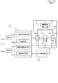
図1は、例となるX線撮影装置Mの概略構成を説明するブロック図である。
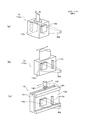
また、図2は、このX線撮影装置Mに用いられるX線発生器11の仕組みを説明する模式図、図3は、X線検出器12の基本構成の例を説明する外観図である。
FIG. 1 is a block diagram illustrating a schematic configuration of an example X-ray imaging apparatus M.
FIG. 2 is a schematic diagram for explaining the mechanism of the
X線撮影装置Mは、図1に示すように、被写体oを挟んで互いに対面するX線発生器11と、X線検出器12cを有したX線検出部12とを備えた移動手段13と、これらX線発生器11、X線検出部12、移動手段13を制御するX線撮影制御手段14とで構成されている。
As shown in FIG. 1, the X-ray imaging apparatus M includes an
X線発生器11は、X線撮影制御手段14によって制御された管電流や管電圧によりX線を発生させるX線管11a、X線管11aから放射されたX線を取り出すための図示しないコリメータ、X線の照射範囲を規制する1次スリット板11b、11b等からなる。ここに、X線管11aはX線源を構成し、コリメータや1次スリット板11b、11bは、照射野制御手段11Dを構成する。
The
図2(a)に示された1次スリット板11bは、X線遮蔽板に縦長(縦横比5:1〜100:1程度、好ましくは10:1〜50:1、さらに好ましくは15:1〜30:1程度)の細溝状空隙11cが形成されたもので、X線管11aで発生したX線は、細溝状空隙11cによって照射範囲が規制され、縦長で幅の狭いX線細隙ビームBとして、被写体oに向かって照射される。X線細隙ビームの進行方向に直行する照射野の形状は長方形でも楕円形でも四隅に丸みを持たせた長方形でも任意の形状でよく、これは細溝状空隙11cの形状を変更することで実現できる。
The
一方、図2(b)に示された1次スリット板11bは、X線遮蔽板により正方形に近い矩形状空隙11d(縦横比1:0.5〜1:1.5、好ましくは1:0.8〜1:1.2程度)が形成されたもので、X線管11aで発生したX線は、矩形状空隙11dによって照射範囲が規制され、所定の広がりを有したX線広域ビームBBとして、被写体oに向かって照射される。
On the other hand, the
X線広域ビームにはX線コーンビームを用いることができる。X線広域ビームの進行方向に直行する照射野の形状は円形でも楕円形でも方形でも八角形でも、任意の形状でよい。すなわち、X線広域ビームは円錐形、四角錐形、八角錐形等さまざまな形状がありうる。
これは矩形状空隙11dの形状を変更することで実現できる。
An X-ray cone beam can be used as the X-ray wide-area beam. The shape of the irradiation field perpendicular to the traveling direction of the X-ray wide-area beam may be any shape, such as a circle, an ellipse, a square, and an octagon. That is, the X-ray wide-area beam can have various shapes such as a cone, a quadrangular pyramid, and an octagonal pyramid.
This can be realized by changing the shape of the
従って、図2(a)、(b)に示された1次スリット板11bからなる照射野制御手段11Dを採用したX線発生器11では、X線撮影制御手段14によって照射野制御手段11Dを制御して、図2(a)、(b)で示した2つの1次スリット板11b、11bの一方を選択することにより、選択された空隙に対応したX線細隙ビームBか、X線広域ビームBBかを選択的に切換えて発生させることができる。
Therefore, in the
また、図2(c)に示された1次スリット板11bは、1枚のX線遮蔽板に上記の細溝状空隙11cと矩形状空隙11dとの両方が形成されたものである。このスリット板11bからなる照射野制御手段11Dを採用した構成のX線発生器11では、X線撮影制御手段14が照射野制御手段11Dの図示されないアクチュエータ等を駆動して、X線管11aの前方に配置された1次スリット板11bを左右にスライドさせることにより、X線細隙ビームBか、X線広域ビームBBかを選択的に切換えて発生させることができる。
In addition, the
X線検出部12は、X線検出器12cを組込んだ構成、又はX線検出器12cとしてのカセットを着脱自在に装着する構成であり、X線検出器12cは、X線イメージセンサとして、X線発生器11が照射するX線細隙ビームB、X線広域ビームBBにそれぞれ対応する、第1のイメージセンサ12aと、第2のイメージセンサ12bとを備える。第1のイメージセンサ12aはX線細隙ビームBに対応した縦長の受光部を有するCCDイメージセンサとし、第2のイメージセンサ12bはX線広域ビームBBに対応した矩形の受光部を有する2次元型のCMOSイメージセンサとするのが好ましい。しかしながら、これだけには限定されず、両者を共にCCDイメージセンサ、あるいはCMOSイメージセンサとしてもよい。
The
すなわち、本発明では、X線イメージセンサの構成を限定しておらず、第1、第2のイメージセンサ12a、12bは、CCDセンサ、あるいはMOSセンサ、CMОSセンサ、TFTセンサ、FTセンサ、X線固体撮像素子、XII(X線イメージインテンシファイア)、MIS型センサのいずれかによって構成される。なお、MIS型センサとは、特許文献4に記載されている金属、絶縁層、半導体層からなる構造を有したMetal Insulator Semiconductorセンサを意味している。
That is, in the present invention, the configuration of the X-ray image sensor is not limited, and the first and
また、上記にては、第2のイメージセンサとして矩形の受光部のセンサを掲げているが、これに限局されず、要はX線広域ビームBBに対応した広がりを持つ2次元型イメージセンサであればよく、円形、楕円形、八角形他様々に考えうる。 In the above description, a rectangular light receiving unit sensor is used as the second image sensor. However, the second image sensor is not limited to this, and is basically a two-dimensional image sensor having a spread corresponding to the X-ray wide-area beam BB. There may be various shapes such as a circle, an ellipse, and an octagon.
図3(a)に示したX線検出器12cでは、長方体の筐体の相対する2面のそれぞれに、第1のイメージセンサ12aと、第2のイメージセンサ12bとが設けられており、X線撮影制御手段14によって図示されないアクチュエータ等を駆動して、この筐体を水平に180度回転させることにより、第1のイメージセンサ12aと、第2のイメージセンサ12bとのいずれかを選択して、X線発生器11と対面させる。
In the
図3(b)に示したX線検出器12cでは、長方体の筐体の1側面に、第1のイメージセンサ12aと、第2のイメージセンサ12bとが共に設けられており、X線撮影制御手段14によって図示されないアクチュエータ等を駆動して、この筐体を水平にスライドさせることにより、第1のイメージセンサ12aと、第2のイメージセンサ12bとのいずれかを選択して、X線発生器11と対面させる。
In the
図3(c)はX線検出部12を、従来のフィルムカセットを装着するパノラマ撮影装置のカセットホルダと同様のカセットホルダ12iと、そのカセットホルダ12iに着脱自在のX線検出器12cで構成した例である。X線検出器12cの側面には、第1のイメージセンサ12aと、第2のイメージセンサ12bとが共に設けられており、カセットホルダ12iは、その上部長手方向に刻設した溝12hに回転軸12f1を接する後述の支持部12aに固定された送りモータ12fにより支持部12aに対してX線照射方向を横切る水平方向に変位可能である。この水平方向の変位は後述の第2のイメージセンサのオフセットに用いることができる。
In FIG. 3C, the
図25は第1のイメージセンサ12aの検出面S1、第2のイメージセンサ12bの検出面S2の形状の例を示している。図25(a)の例は、検出面S1、検出面S2が長方形、矩形の例であるが、例えば図25(b)のような方形の四隅に丸みがつけてある形状でもよく、任意である。
FIG. 25 shows an example of the shape of the detection surface S1 of the
ここで、検出面S1の縦の最大幅の寸法をW1f、検出面S2の縦の最大幅の寸法をW1gとし、検出面S1の横の最大幅の寸法をW2f、検出面S2の横の最大幅の寸法をW2gとすれば、W1f>W1g、W2f<W2gという関係にあるように設定できる。また、これら縦横の寸法は、比率から設定することもでき、W1f/W2f > W1g/W2gという関係になるように設定してもよい。例えば、W2fを1とすれば、W1fを3〜30の比率で設定し、W2gを1とすれば、W1gを0.3〜2の比率で設定するようにしてもよい。 Here, the maximum vertical dimension of the detection surface S1 is W1f, the maximum vertical dimension of the detection surface S2 is W1g, the maximum horizontal dimension of the detection surface S1 is W2f, and the maximum horizontal dimension of the detection surface S2 is W1f. If the significant dimension is W2g, it can be set so that W1f> W1g and W2f <W2g. These vertical and horizontal dimensions can also be set from a ratio, and may be set to have a relationship of W1f / W2f> W1g / W2g. For example, if W2f is 1, W1f may be set at a ratio of 3-30, and if W2g is 1, W1g may be set at a ratio of 0.3-2.
さらに具体的には、W1fを従来、最もパノラマ断層面画像に適した150mmまたは150mm±30mm程度に、W2fを同じく目的とする断層を鮮明に撮像するのに適した10mmまたは10mm±5mm程度に設定し、W1gを数本の歯列または耳のアブミ骨周辺のみを撮像するのに適した120mmまたは120mm±30mm程度に、W2gを同じく数本の歯列または耳のアブミ骨周辺のみを撮像するのに適した120mmまたは120mm±30mm程度に設定してもよい。 More specifically, W1f is conventionally set to about 150 mm or 150 mm ± 30 mm, which is most suitable for panoramic tomographic plane images, and W2f is set to about 10 mm or about 10 mm ± 5 mm, which is also suitable for clear imaging of the target tomography. W1g is about 120 mm or 120 mm ± 30 mm suitable for imaging only several dentitions or ear stapes, and W2g is also used to image only several dentitions or ear stapes. It may be set to about 120 mm or 120 mm ± 30 mm suitable for.
スリットの設定により、前述のX線細隙ビームの上記検出面S1における照射野の形状を上記検出面S1に適合した形状に形成し、前述のX線広域ビームの上記検出面S2における照射野の形状を上記検出面S2に適合した形状に形成すれば、無駄なくX線ビームを照射することができる。 By setting the slit, the shape of the irradiation field of the X-ray slit beam on the detection surface S1 is formed into a shape suitable for the detection surface S1, and the irradiation field of the X-ray wide-area beam on the detection surface S2 is formed. If the shape is formed in a shape suitable for the detection surface S2, the X-ray beam can be irradiated without waste.
第2のイメージセンサ12bを変形し、図25(c)のイメージセンサ12b´のようなイメージセンサを採用してもよい。このイメージセンサ12b´には、上記の検出面S1と検出面S2が共に設定される。イメージセンサ12b´は、縦の最大幅の寸法が上記検出面S1の縦の最大幅の寸法W1fに設定され、横の最大幅の寸法が上記検出面S2の横の最大幅の寸法をW2gに設定されている。
The
そのため、上記検出面S1と上記検出面S2が同一のイメージセンサ12b´の中撮像面上に共に設定できる。このイメージセンサを採用する場合は、第1のイメージセンサ12aと、第2のイメージセンサ12bとを同一のイメージセンサ12b´により構成できる。
Therefore, both the detection surface S1 and the detection surface S2 can be set on the middle imaging surface of the
このイメージセンサ12b´を用いて、図3(c)のX線検出器12cの変形として構成したものが図25(d)のX線検出器12cである。
図25(d)のX線検出器12cにおいては、図3(c)のX線検出器12cの第1のイメージセンサ12aと、第2のイメージセンサ12bが同一のイメージセンサ12b´によって構成されている。
A modification of the
In the
すなわち、イメージセンサ12b´は、X線細隙ビームを受けて被写体の画像を撮像するX線イメージセンサであり、かつ、X線広域ビームを受けて、被写体の画像を撮像するイメージセンサとして用いることができる。
That is, the
イメージセンサ12b´の横の幅W2gは、例えば被写体となる患者の頭部全体あるいは歯列全体を一度に撮影できるものではないが、縦の幅が例えばパノラマ断層面画像撮影に用いられる程度に充分な寸法に設定される。また、横の幅W2gの寸法が小さいことについては、支持部13aを水平方向に変位させて位置を変え、複数回にわたって撮影することで広い範囲の画像を合成することも可能である。
The horizontal width W2g of the
なお、本発明の全ての第2のイメージセンサ12bの横の幅を、歯科、耳鼻科といった特定の医療分野において必要な関心領域s(例えば歯列弓のみ、あるいは歯列の中の特定の部分のみ、耳のアブミ骨の周囲のみといった関心領域)の横の幅に対応したサイズに設定しておき、第2のイメージセンサ12bに照射される広域ビームBBの照射野の大きさも、その第2のイメージセンサ12bに必要なだけのサイズに設定すれば、関心領域のみに向けて広域ビームを照射することができ、被爆量を軽減できる。
Note that the horizontal width of all the
同様に、第2のイメージセンサ12bの縦の幅を、関心領域sの縦の幅に対応したサイズに設定しておき、第2のイメージセンサ12bに照射される広域ビームBBの照射野の大きさも、その第2のイメージセンサ12bに必要なだけのサイズに設定してもよい。
Similarly, the vertical width of the
移動手段13は、X線発生器11と、X線検出部12とを備えた支持部13aと、この支持部13aの回転軸Aを回転自在な状態で垂直に懸架保持し、更に、この回転軸Aを水平面に沿って移動できる軸移動台13bと、被写体oを位置決めする保持手段13cとで構成されている。支持部13aの旋回移動や、支持部13aの回転軸の水平移動は、X線撮影制御手段14の制御する、おのおの独立したステッピングモータが駆動源に用いられている。更に、同様なステッピングモータによって保持手段13cを上下動させるようにしてもよい。
The moving means 13 holds the
なお、X繊細隙ビームBあるいはX線広域ビームBBの照射角は、基本的には、水平面と平行であるが、これには限定されない。すなわち、被写体oに対して、水平面に対して斜めの照射角でX線照射する構成も考えられる。というのは、義歯などの金属部分は、X線撮影でのアーチファクトが大きいので、金属部分を避けて撮りたいことがあるからである。これは、特にX線CT画像撮影で問題となる。従って、その場合には、金属部分を避けるように、被写体oに対して斜めにX繊細隙ビームBあるいはX線広域ビームBBが照射されるようにするのが望ましい。 The irradiation angle of the X fine slit beam B or the X-ray wide-area beam BB is basically parallel to the horizontal plane, but is not limited to this. That is, a configuration in which the subject o is irradiated with X-rays at an oblique irradiation angle with respect to the horizontal plane is also conceivable. This is because metal parts such as dentures have a large artifact in X-ray photography, and there are cases where it is desired to take pictures while avoiding metal parts. This is a problem particularly in X-ray CT image capturing. Therefore, in that case, it is desirable to irradiate the subject o with the X-fine slit beam B or the X-ray wide-area beam BB so as to avoid the metal portion.
X線撮影制御手段14は、移動手段13を駆動するステッピングモータを有するモータ制御部13d、モニタテレビ等にX線画像等の情報を表示する表示部15a、キーボードやマウス等の操作を受付ける操作部15b等が接続されており、機能的要素として、X線発生器11のX線管11aの管電流や管電圧を制御し、更に照射野制御手段11Dの1次スリット板11bを操作して、X線細隙ビームBか、X線広域ビームBBかを選択的に切換えて発生させるX線発生制御手段14aと、第1のイメージセンサ12aと第2のイメージセンサ12bのいずれかをX線発生器11と対面させた状態にして動作させ、被写体oを透過したX線像のデータを取得するイメージセンサ制御手段14bと、モータ制御部13dを制御することにより移動手段13を動作させ、X線発生器11と、X線検出部12とを撮影の種別に応じた撮影軌道に沿って移動させる撮影軌道制御手段14cと、取得したX線像のデータから透過画像や断層面画像を生成する画像生成手段14dとを備える。
The X-ray
表示部15a、操作部15bは、被写体oの広範囲な画像、すなわちスカウトビュー画像として、目的の断層撮影に先だって撮影された画像を表示し、被写体oの内部で断層撮影されるべき断層面あるいは診断部位である関心領域sを選択し、更に、関心領域sについて、断層面画像の撮影種別を選択する撮影種別選択手段15を構成する。ここに、スカウトビュー画像は、予備撮影ないし予備診断として用いられるものである。
The
次いで、X線撮影装置Mの基本動作であるスカウトビュー画像の撮影、撮影種別の選択、断層面画像の撮影を順に説明する。 Next, imaging of a scout view image, selection of an imaging type, and imaging of a tomographic plane image which are basic operations of the X-ray imaging apparatus M will be described in order.
スカウトビュー画像の撮影では、X線発生器11と、X線検出部12とを所定の撮影軌道に沿って同期的に移動させながら、X線細隙ビームBによって被写体oを照射して、その画像を得ることが特徴である。また、このようなスカウトビュー画像としては、リニアスキャン透過画像や、パノラマ断層面画像等が利用可能であり、いずれを利用するかという撮影種別の選択は、撮影種別選択手段15によって、予め設定しておくようになっている。
In capturing a scout view image, the
本出願のいずれの発明においても、スカウトビュー画像の撮影種別は1つでも複数でも構わず、スカウトビューから撮影する断層面画像の撮影種別も1つでも複数でも構わない。 In any invention of the present application, there may be one or a plurality of imaging types of scout view images, and there may be one or a plurality of imaging types of tomographic image captured from the scout view.
また、第1のイメージセンサでスカウトビュー画像を撮影し、第2のイメージセンサで断層面画像を撮影するのみならず、第2のイメージセンサでスカウトビュー画像を撮影し、第1のイメージセンサで断層面画像を撮影してもよいし、また、第1のイメージセンサでスカウトビュー画像を撮影し、第1のイメージセンサで断層面画像を撮影するようにしてもよい。 In addition to taking a scout view image with the first image sensor and taking a tomographic image with the second image sensor, the scout view image is taken with the second image sensor and the first image sensor. A tomographic image may be taken, or a scout view image may be taken by the first image sensor, and a tomographic image may be taken by the first image sensor.
また、第2のイメージセンサでスカウトビュー画像を撮影し、第2のイメージセンサで断層面画像を撮影するようにしてもよい。さらに、これらの組合せを重複的に可能としてもよく、この組合せは自由である。 Further, a scout view image may be taken with the second image sensor, and a tomographic plane image may be taken with the second image sensor. Further, these combinations may be duplicated, and this combination is free.
すなわち、第1のイメージセンサでスカウトビュー画像を撮影し、第2のイメージセンサで断層面画像を撮影する例は、例えば、第1のイメージセンサを用いてパノラマ断層面画像、セファロ画像またはリニアスキャン透過画像をスカウトビュー画像とし、第2のイメージセンサを用いて断層面画像としてX線CT画像を撮影する構成である。 That is, an example in which a scout view image is captured by the first image sensor and a tomographic plane image is captured by the second image sensor is, for example, a panoramic tomographic plane image, a cephalometric image, or a linear scan using the first image sensor. The transmission image is a scout view image, and an X-ray CT image is captured as a tomographic image using a second image sensor.
また、第2のイメージセンサでスカウトビュー画像を撮影し、第1のイメージセンサで断層面画像を撮影する例は、例えば、第2のイメージセンサを用いて単純撮影画像をスカウトビュー画像とし、第1のイメージセンサを用いて断層面画像としてパノラマ断層面画像を撮影する構成である。 An example in which a scout view image is captured by the second image sensor and a tomographic plane image is captured by the first image sensor is, for example, a simple captured image is used as a scout view image using the second image sensor, In this configuration, a panoramic tomographic plane image is captured as a tomographic plane image using one image sensor.
第1のイメージセンサでスカウトビュー画像を撮影し、第1のイメージセンサで断層面画像を撮影する例は、例えば、第1のイメージセンサを用いてリニアスキャン透過画像またはセファロ画像をスカウトビュー画像とし、第1のイメージセンサを用いて断層面画像としてパノラマ断層面画像を撮影する構成である。 An example in which a scout view image is captured by the first image sensor and a tomographic image is captured by the first image sensor is, for example, a linear scan transmission image or a cephalo image is used as the scout view image using the first image sensor. The panorama tomographic image is captured as a tomographic image using the first image sensor.
第2のイメージセンサでスカウトビュー画像を撮影し、第2のイメージセンサで断層面画像を撮影する例は、例えば、第2のイメージセンサを用いて単純撮影画像をスカウトビュー画像とし、第2のイメージセンサを用いて断層面画像としてX線CT画像またはリニア断層面画像を撮影する構成である。 An example of taking a scout view image with the second image sensor and taking a tomographic image with the second image sensor is, for example, using the second image sensor as a scout view image, In this configuration, an X-ray CT image or a linear tomographic image is captured as a tomographic image using an image sensor.
これらの組合せの重複の例は、例えば、第1のイメージセンサでスカウトビュー画像を撮影し、第2のイメージセンサで断層面画像を撮影する例は、例えば、第1のイメージセンサを用いてパノラマ断層面画像、セファロ画像またはリニアスキャン透過画像をスカウトビュー画像とし、第2のイメージセンサを用いて断層面画像としてX線CT画像を撮影する構成において、さらに第2のイメージセンサを用いて単純撮影画像をスカウトビュー画像とし、第1のイメージセンサを用いて断層面画像としてパノラマ断層面画像を撮影可能とした構成である。 An example of overlapping of these combinations is, for example, a case where a scout view image is taken with a first image sensor, and an example where a tomographic plane image is taken with a second image sensor is, for example, a panorama using a first image sensor. In a configuration in which a tomographic image, a cephalo image, or a linear scan transmission image is used as a scout view image, and an X-ray CT image is captured as a tomographic image using a second image sensor, simple imaging using a second image sensor is further performed. The image is a scout view image, and a panoramic tomographic image can be taken as a tomographic image using the first image sensor.
煩雑になるので、これ以上詳述しないが、図22のスカウトビューと断層面画像撮影の中で、さまざまな組合せが可能である。 Although it will be complicated, it will not be described in detail any more, but various combinations are possible in the scout view and tomographic image imaging of FIG.
この撮影において、撮影軌道制御手段14cは、図示されない撮影軌道メモリに蓄積された軌道データを読み出し、モータ制御部13dを通じて、移動手段13を制御することにより、X線発生器11と、X線検出部12とを、その読み出された軌道データで規定される撮影軌道に沿って同期的に移動させる。また、X線発生制御手段14aは、図示されない照射強度メモリに蓄積された強度データ、すなわちプロファイルに従って、X線発生器11からX線細隙ビームBにより被写体oを照射する。一方、イメージセンサ制御手段14bは、第1のイメージセンサ12aによって被写体oを透過したX線を計測させ、そのデータを画像生成手段14dに送信させている。この撮影が終了すれば、画像生成手段14dは、送信されてきた一連のデータを時系列に従って配列して、スカウトビュー画像を生成できる。なお、上記プロファイルは、被写体oとなる被験者の性別や体格などに従って選択するようにしてもよく、あるいは、プロファイルによらず、第1のイメージセンサ12aが計測したX線強度をフィードバックして制御するようにしてもよい。
In this imaging, the imaging trajectory control means 14c reads the trajectory data stored in an imaging trajectory memory (not shown), and controls the moving means 13 through the
撮影種別の選択では、表示部15aに、スカウトビュー画像として撮影されたリニアスキャン透過画像や、パノラマ断層面画像等が、その画像上で移動可能なカーソルと共に表示され、オペレータは、例えば操作部15bのマウス等を用いて、そのカーソルを断層面や診断部位などの関心領域sへ移動させてから、マウスクリック等の操作によって関心領域sを確定することができる。そして、所定のキーを押す等の操作によって、その関心領域sについて撮影される断層面画像の撮影種別を選択すれば、断層面撮影が開始される。なお、断層面画像としては、リニア断層面画像、X線CT画像、パノラマ断層面画像などが選択可能である。
In the selection of the photographing type, a linear scan transmission image, a panoramic tomographic image, and the like photographed as a scout view image are displayed on the
断層面画像の撮影では、X線発生器11と、X線検出部12とを所定の撮影軌道に沿って同期的に移動させながら、例えばX線CT画像やリニア断層面画像の撮影であれば、X線発生器11からX線広域ビームBBを照射させ、X線検出器12cの第2のイメージセンサ12bによって、所定の広がりを有したフレーム画像として、被写体oの透過画像を複数撮影して、撮影軌道の位置に応じた複数の透過画像を得たのち、それらを合成、あるいは演算処理する画像処理により、関心領域sの断層面画像を得る。
また、例えばパノラマ断層面画像の撮影であれば、X線発生器11からX線細隙ビームBを第1のイメージセンサに向けて照射させて得た透過画像を演算で画像処理し、パノラマ断層面画像を得る。
For tomographic plane imaging, for example, X-ray CT images and linear tomographic plane images can be captured while the
Further, for example, in the case of photographing a panoramic tomographic plane image, a transmission image obtained by irradiating the X-ray slit beam B from the
この撮影において、撮影軌道制御手段14cは、図示されない撮影軌道メモリに蓄積された軌道データを読み出し、モータ制御部13dを通じて、移動手段13を制御することにより、X線発生器11、X線検出部12を、その読み出された軌道データで規定される断層面画像撮影用の撮影軌道に沿って同期的に移動させる。また、X線発生制御手段14aは、所定の撮影軌道の位置となったとき、図示されない照射強度メモリに蓄積された強度データ、すなわちプロファイルに従って、X線発生器11からX線広域ビームBBを被写体oの関心領域sに向けて照射させる一方、イメージセンサ制御手段14bは、第2のイメージセンサ12bや第1のイメージセンサ12aによって関心領域sを透過したX線を受光させ、透過画像を画像生成手段14dに送信させている。この撮影が終了すれば、画像生成手段14dは、送信されてきた透過画像に対して所定の処理を行い、関心領域sの断層面画像を生成することができる。なお、上記プロファイルは、被写体oとなる被験者の性別や体格などに従って選択するようにしてもよく、あるいは、プロファイルに寄らず、第2のイメージセンサ12bや第1のイメージセンサ12aが受光し、計測したX線強度をフィードバックして制御するようにしてもよい。
In this imaging, the imaging trajectory control means 14c reads the trajectory data stored in an imaging trajectory memory (not shown), and controls the moving means 13 through the
ここで、スカウトビュー画像としてリニアスキャン透過画像、あるいはパノラマ断層面画像を撮影する際の撮影軌道と、得られる画像の例を、図に従って説明する。 Here, an imaging trajectory when capturing a linear scan transmission image or a panoramic tomographic plane image as a scout view image, and an example of an obtained image will be described with reference to the drawings.
図4は、スカウトビュー画像としてX線発生器とX線検出部を同方向に同期移動させるリニアスキャン透過画像を撮影する際に、X線発生器11、X線検出部12が同期的に移動する撮影軌道を説明する平面図、図5は、その撮影で得られる被写体oのリニアスキャン透過画像の例で、撮影種別の選択において表示される画像である。この例では、被写体oとして、人の下顎部が用いられており、関心領域sを指定するための十文字カーソルも共に描かれている。
FIG. 4 shows that the
この場合、撮影軌道制御手段14cは、X線細隙ビームBを照射するようにしたX線発生器11を、移動手段13を制御することにより、位置(p1)から位置(p2)に向かう撮影軌道に沿って移動させつつ、X線検出器12cの第1のイメージセンサ12aを、位置(q1)から位置(q2)に向かう撮影軌道に沿って同期的に移動させる。このような撮影軌道に従った撮影によって、図5(a)に示すような被写体oの正面リニアスキャン透過画像が得られる。
In this case, the imaging trajectory control means 14c controls the
また同様に、X線細隙ビームBを照射するようにしたX線発生器11を位置(p3)から位置(p4)に向かう撮影軌道に沿って移動させつつ、X線検出器12の第1のイメージセンサ12aを位置(q3)から位置(q4)に向かう撮影軌道に沿って同期的に移動させる撮影により、図5(b)に示すような被写体oの側面リニアスキャン透過画像を得ることができる。
Similarly, the
図4においては、図の真上に歯列弓の前歯側頂点が向かっていて、X線発生器11が位置(p1)から位置(p2)に向かって図の右から左に移動し、同じく第1のイメージセンサ12aが、位置(q1)から位置(q2)に向かって図の右から左に移動している。
また、X線発生器11が位置(p3)から位置(p4)に向かって図の上から下に移動し、同じく第1のイメージセンサ12aが、位置(q3)から位置(q4)に向かって図の上から下に移動している。
In FIG. 4, the apex side of the dental arch is directly above the figure, and the
In addition, the
このようにして撮影した被写体oの正面と側面とのリニアスキャン透過画像は、表示部15aに同時に表示され、被写体oの関心領域sの設定に利用される。
被写体oに対して異なる2方向からスカウトビュー画像を取得することを、「2方向スカウト」と呼ぶこととする。
The linear scan transmission images of the front and side surfaces of the subject o photographed in this way are simultaneously displayed on the
Acquisition of a scout view image from two different directions with respect to the subject o is referred to as “two-way scout”.
本願にいうパノラマ断層面画像は、歯列弓に沿った歯牙、顎の断層画像であり、このような撮影軌道に従った撮影によって、図7に示すような被写体oのパノラマ断層面画像が得られる。 The panoramic tomographic plane image referred to in the present application is a tomographic image of teeth and jaws along the dental arch, and a panoramic tomographic plane image of the subject o as shown in FIG. It is done.
なお、パノラマ断層面画像撮影時の軌道については、図24に示すように、X線細隙ビームの移動軌跡が歯列弓の前歯部に向いて突出する頂点を境として左右対象な略三角形状の包絡線軌跡を描くようにX線検出器とX線発生器を移動させる周知のパノラマX線撮影装置の構成を採用することができる。 As shown in FIG. 24, the trajectory during panoramic tomographic image shooting is a substantially triangular shape that is subject to left and right with the vertex of the X-ray slit beam moving toward the front tooth portion of the dental arch as a boundary. It is possible to adopt a configuration of a known panoramic X-ray imaging apparatus that moves the X-ray detector and the X-ray generator so as to draw an envelope trajectory.
図24は、X線発生器11から第1のイメージセンサ12aに向けて照射されるX線細隙ビームBの軌跡が包絡線ENを描く様子を示している。すなわち、支持部13aの旋回によるX線発生器11と第1のイメージセンサ12aの旋回と、支持部13aの旋回軸Aの移動との組合せでX線細隙ビームBの軌跡が包絡線ENを形成している。
FIG. 24 shows how the trajectory of the X-ray slit beam B irradiated from the
図23は、X線細隙ビームBにより、第2のイメージセンサ12bを用いてスカウトビュー画像を得る例である。基本的構成は図4におけるものと同じであるが、X線検出部が撮影中は移動せず、第2のイメージセンサ12bを固定して撮影する点が異なっている。図23においては、図の真上に歯列弓の前歯側頂点が向かっていて、X線発生器11が位置(p51)から位置(p52)に向かって図の右から左に移動してスカウトビューを取得している。この撮影方法で前述の2方向スカウトを取得できることはもちろん可能である。
FIG. 23 is an example in which a scout view image is obtained by the X-ray slit beam B using the
第2のイメージセンサ12bでスカウトビューを取得する場合は、X線広域ビームBBを用いて単純なX線透視画像を得ればよいのであるが(本願では「単純撮影」と称することとする。)、図23の構成によることもできる。
When a scout view is acquired by the
図23の構成の利点は、第2のイメージセンサ12bのうち、限られた領域のみの照射でも可能であるという点である。例えば、スカウトビューとしては片方の顎関節近辺で充分であるという場合に、片方の顎関節近辺のみの照射が可能である。この撮影方法を本願では「スキャンX線画像撮影」と称することとする。
The advantage of the configuration of FIG. 23 is that irradiation with only a limited area of the
更に、断層面画像としてリニア断層面画像、あるいはX線CT画像を撮影する際の撮影軌道の例を図に従って説明する。また、断層面画像としてパノラマ断層面画像を撮影することも可能である。 Furthermore, an example of an imaging trajectory when a linear tomographic image or an X-ray CT image is acquired as a tomographic image will be described with reference to the drawings. It is also possible to take a panoramic tomographic image as a tomographic image.
リニア断層面画像の撮影は、被写体oに対して、常に目的とする所定の断層面のみを中心にして、投影角度を変えてX線広域ビームBBを照射して、所定の断層面のみが強調されるように、所定の断層面以外の部位を透過したX線による画像情報を分散させることにより断層面画像を得るものである。本願にいうリニア断層面とは、上記の、中心となって撮影される所定の断層面である。撮影位置は、撮影軌道上の投影角度が異なる複数の点を含んでいる。なお、リニア断層面画像の撮影を、X線細隙ビームBを用いてなすことも可能である。 In taking a linear tomographic plane image, the subject o is always irradiated with the X-ray wide-area beam BB with the projection angle changed around only the target predetermined tomographic plane, and only the predetermined tomographic plane is emphasized. As described above, a tomographic image is obtained by dispersing image information of X-rays transmitted through a part other than a predetermined tomographic plane. The linear tomographic plane referred to in the present application is the above-described predetermined tomographic plane that is photographed at the center. The imaging position includes a plurality of points with different projection angles on the imaging trajectory. It is also possible to take a linear tomographic image using the X-ray slit beam B.
また、X線CT画像の撮影は、被写体oに設定された関心領域sが常時含まれるように、その関心領域sを中心として、X線広域ビームBBを少なくとも180以上の角度で旋回させて、所定の旋回角度毎に撮影した多数の透過画像について、逆投影像を算出することにより、任意方向の断層面画像を得るものである。 Further, X-ray CT imaging is performed by rotating the X-ray wide-area beam BB at an angle of at least 180 or more around the region of interest s so that the region of interest s set on the subject o is always included. A tomographic plane image in an arbitrary direction is obtained by calculating a back projection image for a large number of transmission images photographed for each predetermined turning angle.
パノラマ断層面画像の撮影は、被写体oに設定された関心領域sである歯列弓に向けて、X線細隙ビームBが垂直に照射されるように、かつ歯列弓を細分化した透過画像を順次重ね合わせて、あるいは合成して1枚のパノラマ断層面画像を得るものであるが、微視的には異なる角度から撮影された画像の重ね合わせあるいは合成となる。すなわち、パノラマ断層面画像では、X線細隙ビームで取得した画像について、歯列弓の断面が強調されるように順次重ね合わせあるいは合成が実行される。 The panoramic tomographic image is captured in such a manner that the X-ray slit beam B is vertically irradiated toward the dental arch which is the region of interest s set on the subject o and the dental arch is subdivided. The images are sequentially overlapped or synthesized to obtain a single panoramic tomographic image, but microscopically, images taken from different angles are superimposed or synthesized. That is, in the panoramic tomographic plane image, the images acquired with the X-ray slit beam are sequentially superimposed or synthesized so that the cross section of the dental arch is emphasized.
図8(a)は、断層面画像としてリニア断層面画像を撮影する際に、X線発生器11、X線検出器12が同期的に移動する撮影軌道を説明する平面図である。ここに、被写体oには、関心領域sとして、断層面が設定されている。図8(b)は、図8(a)とX線発生器11、X線検出部12が移動する軌跡が異なるものである。すなわち、図8(a)の軌跡ではX線発生器11とX線検出器12cとが図の関心領域sで示される、目的とする所定の断層面を挟んで互いに逆方向に直線的移動をするのに対して、図8(b)の軌跡ではX線発生器11とX線検出器12cとが互いに逆方向に円弧移動している。
FIG. 8A is a plan view illustrating an imaging trajectory in which the
この場合、撮影軌道制御手段14cは、X線広域ビームBBを照射するようにしたX線発生器11を、移動手段13を制御することにより、位置(p31)から位置(p33)に向かう撮影軌道に沿って移動させつつ、X線検出器12cの第2のイメージセンサ12bを位置(q31)から位置(q33)に向かう撮影軌道に沿って同期的に移動させる。このような撮影軌道に従った撮影で、リニア断層面画像を合成することができる。
In this case, the imaging trajectory control means 14c controls the
例えば、撮影軌道に従った撮影の間、透過画像を逐次単位フレーム画像として獲得し、フレーム画像同士を所望の断層面の部分のみを重ね合わせてリニア断層面画像に合成することができる。 For example, during imaging in accordance with the imaging trajectory, a transmission image can be sequentially acquired as a unit frame image, and the frame images can be combined with a linear tomographic image by superimposing only a desired tomographic part.
また、例えば、撮影軌道に従った撮影の間、複数の画像に分けた透過画像を得ることなく、単一の画像として画像データを蓄積した、1枚のリニア断層面画像を取得することもできる。これは、目標であるリニア断層面以外に存在する部位は情報が分散するので、特定のリニア断層面の情報のみが蓄積されて強調されるという従来のフィルムによる撮影と全く同じ原理による。 In addition, for example, one linear tomographic image in which image data is accumulated as a single image can be acquired without obtaining a transmission image divided into a plurality of images during imaging according to the imaging trajectory. . This is based on the same principle as the conventional film photographing in which only the information on a specific linear tomographic plane is accumulated and emphasized because information is dispersed in portions other than the target linear tomographic plane.
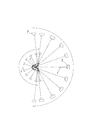
図9は、断層面画像としてX線CT画像を撮影する際に、X線発生器11、X線検出部12が同期的に移動する撮影軌道を説明する平面図である。ここに、被写体oには、関心領域sとして、円柱状の診断部位が設定されている。
FIG. 9 is a plan view illustrating an imaging trajectory in which the
この場合、撮影軌道制御手段14cは、X線広域ビームBBを照射するようにしたX線発生器11を、移動手段13を制御することにより、位置(p41)から位置(p43)に向かう撮影軌道に沿って移動させつつ、X線検出器12cの第2のイメージセンサ12bを位置(q41)から位置(q43)に向かう撮影軌道に沿って同期的に移動させる。
X線発生器11は、位置(p41)から位置(p43)に向かって、第1のイメージセンサ12aは、位置(q41)から位置(q43)に向かって、X線発生器11と第2のイメージセンサ12bとの旋回中心を関心領域sにおいて、円を描いて旋回移動する。
X線CT撮影に必要な旋回角度は、最低180°である。
In this case, the imaging trajectory control means 14c controls the
The
The turning angle required for X-ray CT imaging is at least 180 °.
このような撮影軌道に従った撮影で得た透過画像を、公知の手法で逆投影することにより、関心領域sの任意断面について断層面画像を合成することができる。 A tomographic plane image can be synthesized for an arbitrary cross section of the region of interest s by back-projecting a transmission image obtained by imaging according to such an imaging trajectory by a known method.
ここに、上記スカウトビュー画像の撮影、撮影種別選択、断層面画像の撮影からなる一連の動作を、図10〜12のフローチャートとして示す。 Here, a series of operations including imaging of the scout view image, selection of the imaging type, and imaging of the tomographic plane image are shown as flowcharts in FIGS.
図10は、スカウトビュー画像として2方向のリニアスキャン透過画像を撮影(前述の2方向スカウト)し、撮影種別選択でリニア断層面画像を選択し、その断層面画像を撮影する場合の手順を示すフローチャートである。 FIG. 10 shows a procedure in which a linear scan transmission image in two directions is captured as the scout view image (two-way scout described above), a linear tomographic image is selected by selecting the imaging type, and the tomographic image is captured. It is a flowchart.
ここに、ステップ101、102では、2方向のリニアスキャン透過画像を撮影し、ステップ103〜106では、関心領域を選択し、更に断層面画像としてリニア断層面画像を選択し、ステップ107〜108では、その断層面画像を撮影している。
Here, in
図11は、スカウトビュー画像としてパノラマ断層面画像を撮影し、撮影種別選択でリニア断層面画像を選択し、その断層面画像を撮影する場合の手順を示すフローチャートである。 FIG. 11 is a flowchart showing a procedure when a panoramic tomographic plane image is captured as a scout view image, a linear tomographic plane image is selected by selecting an imaging type, and the tomographic plane image is captured.
ここに、ステップ201、202では、パノラマ断層面画像を撮影し、ステップ203〜206では、関心領域を選択し、更に断層面画像としてリニア断層面画像を選択し、ステップ207〜208では、その断層面画像を撮影している。
Here, panoramic tomographic plane images are taken in
上記は、図10、図11においてスカウトビュー画像からリニア断層面画像を撮影する場合であるが、さらに、図20、図21に示すように、CTモードが選択できるようにしてもよい。ステップ106、206のリニア断層モードか、ステップ506、606のCTモードかの選択が可能であり、ステップ507、607では、通知された座標のポイントがX線CT画像の中央になるように装置を移動している。
The above is a case where a linear tomographic image is captured from a scout view image in FIGS. 10 and 11, but the CT mode may be selected as shown in FIGS. 20 and 21. It is possible to select the linear tomographic mode in
リニア断層モードに進んだ場合はステップ108、208のリニア断層面画像撮影を行い、CTモードに進んだ場合はステップ508、608のX線CT画像の撮影を行う。
When proceeding to the linear tomographic mode, linear tomographic plane image capturing at
上記のリニア断層面画像撮影とX線CT画像の撮影を共に前記X線検出器12cの第2のイメージセンサ12bで行うことができ、このように複数種の断層面画像撮影が可能である。
Both the above-described linear tomographic image capturing and X-ray CT image capturing can be performed by the
図22は、どのようなスカウトビューからどのような断層面画像撮影ができるか、その組合せをまとめた表である。 FIG. 22 is a table summarizing the combinations of what kind of tomographic images can be taken from what kind of scout view.
図12は、スカウトビュー画像として1方向のリニアスキャン透過画像を撮影(1方向スカウト)し、撮影種別選択でパノラマ断層面画像を選択し、その断層面画像を撮影する場合の手順を示すフローチャートである。 FIG. 12 is a flowchart showing a procedure in the case of taking a linear scan transmission image in one direction as a scout view image (one-way scout), selecting a panoramic tomographic plane image by selecting an imaging type, and capturing the tomographic plane image. is there.
ここに、ステップ301、302では、1方向のリニアスキャン透過画像を撮影し、ステップ203〜306では、関心領域を選択し、更に断層面画像としてパノラマ断層面画像を選択し、ステップ307〜308では、その断層面画像を撮影している。
Here, in
ついで、本発明によるX線撮影装置Mのより具体的な例を図に従って説明する。
図13は、そのX線撮影装置Mの斜視図を示し、図14、15はセファロ画像撮影手段18を更に付加した例の平面図、側面図を示している。
Next, a more specific example of the X-ray imaging apparatus M according to the present invention will be described with reference to the drawings.
FIG. 13 is a perspective view of the X-ray imaging apparatus M, and FIGS. 14 and 15 are a plan view and a side view of an example in which a cephalo image imaging means 18 is further added.
デジタルX線断層面撮影装置Mは、X線発生器11と、X線検出部12とを備えた移動手段13と、この移動手段13を強固に支持する本体フレーム16から構成されている。
The digital X-ray tomography apparatus M includes a moving means 13 having an
移動手段13は、X線発生器11とX線検出器12とが固定された支持部13aと、この支持部13aの回転軸Aと直交する平面X−Y上で、Z方向の回転軸Aを水平移動させる軸移動台13bとからなる。この軸移動台13bは、移動手段13の機構を駆動するステッピングモータを有するモータ制御部13dと、X軸用ステッピングモータ、Y軸ステッピングモータによって、X−Y平面を自在に移動可能な軸移動機構を構成する軸用スライド部を有し、これに連結している回転軸を水平に移動させるとともに、回転軸用ステッピングモータによって、支持部13aを自在に旋回させることもできる。なお、移動手段13は、Z軸用ステッピングモータにより、本体フレーム16に沿った上下動も可能である。
The moving means 13 includes a
しかしながら、被写体oとなる患者が立位となる構成も、仰臥位となる構成も可能であるから、支持部13aの回転軸方向はこの例だけに限定されず、任意で構わない。
However, since the patient who is the subject o can be in a standing position or a supine position, the rotation axis direction of the
X線発生器11は、図2で説明した基本構成に基づくもので、固定型アノードを有するX線管11a、金属製コリメータ、X線細隙ビームB用の細溝状空隙11cとX線広域ビームBB用の矩形状空隙11dを有する1次スリット板11b等から構成されており、X線細隙ビームB、X線広域ビームBBのいずれかを選択的に照射する。ここにX線管11aはX線源を構成し、金属製コリメータや1次スリット板11bは、照射野制御手段11Dを構成する。
The
図16は、1次スリット設定の例である。カセット(撮影の種類)が切換えられるとき、または同じカセットで撮影の種類が切換えられるとき、X線発生器13から照射されるX線の照射野形状とX線検出部12側の受光形状が撮影形態に応じて切換えられる。X線発生器11を含むハウジングの中には、X線管球11aからなるX線源Xが内蔵され、このハウジングのX線検出部12に対向する前面には、1次スリットSL1を有するX線遮蔽板とその1次スリットの形状を変更する調整機構などを含むスリットモジュールSLが配置される。X線源Xの前面側に設けられる1次スリット板SL2(図2における1次スリット板11bに相当)には、1次スリットSL1として、パノラマ断層面画像撮影用の縦長のスリットSL3(図2における細溝状空隙11c)と、X線CT撮影用の矩形のスリットSL4(図2における矩形状空隙11d)と、長尺のセファロ撮影用スリットSL5(図2における細溝状空隙11c)が形成されていて、カセットが変更されると、スリットモジュールSLでは、その駆動モータSMにより、そのカセットに対応する1次スリットSL1を設定する。
FIG. 16 is an example of primary slit setting. When the cassette (type of imaging) is switched, or when the type of imaging is switched with the same cassette, the X-ray irradiation field shape irradiated from the
X線検出部12を構成するX線検出器12cは、図3で説明した基本構成に基づくもので、X線を可視光に変換する蛍光フィルタ、第1のイメージセンサ12aとしてX線細隙ビームBに対応した縦長の受光部を有するCCDイメージセンサ、第2のイメージセンサ12bとしてX線広域ビームBBに対応した短形の受光部を有するCMOSイメージセンサ、更に散乱X線を遮蔽する2次スリット板等を内蔵したカセット12ccとして構成され、このカセット12cがカセットホルダ12gに着脱可能に取り付けられている。このカセット12ccは、Xフィルムを内蔵した別のカセットと交換することも可能である。
The
本体フレーム16に設けられた収容フレーム17の側面には、表示灯や操作スイッチから構成される表示部15a、操作部15bが設けられ、さらに内部には、CPU等からなる制御部が格納されている。また、収容フレーム17には、被写体oを位置決めする保持手段13cも取り付けられている。
On the side surface of the
保持手段13cの正面から見て中央に見えるのは、患者が顎を置くチンレスト13gである。該チンレスト13gは、上下昇降或いは傾動可能とされ患者の体形に合わせてその位置付けがなされる。チンレスト13gをこのように可動に構成することで、例えば上顎、下顎などの撮影部位ごとに照射線の水平面に対する傾きを調節することや、上方に位置する顎関節と、下方に位置する下顎先端とのように、上下に離れた部位をうまく照射野の中心に位置するように調節することもできる。
What is seen in the center when viewed from the front of the holding means 13c is a
ここで、移動手段13と収容フレーム17の構成を詳述しておく。
軸移動台13bは、図13の例では、患者の体格に合わせて本体フレーム16に対して昇降変位する。軸移動台13bと収容フレーム17は一体的に形成されている。従って、X線発生器11と、X線検出部12とは収容フレーム17及び保持手段13cと共に昇降することになる。
Here, the structure of the moving
In the example of FIG. 13, the axis moving table 13b is displaced up and down with respect to the
しかし、上述の、収容フレーム17と、X線発生器11とX線検出部12の昇降を伴う軸移動台13bとを別体に構成して、それぞれが本体フレーム16に対して独立に変位するようにしても構わない。また、収容フレーム17ないし保持手段13dに対し、X線発生器11が変位するように構成しても構わない。本出願人の出願に係る上記特許文献3は、そのように上述の収容フレーム17と軸移動台13bとを別体に構成した例や、収容フレーム17ないし保持手段13cに対し、X線発生器11が変位するように構成した例を開示している。
However, the
上記特許文献3においては、上述の収容フレーム17に相当する部分を「患者フレーム」、軸移動台13bに相当する部分を「昇降本体」と称しており、その目的は、撮影可能な領域を広げることであると共に、例えば撮影部位ごとに照射線の水平面に対する傾きを調節することであり、上方に位置する顎関節と、下方に位置する下顎先端とのように、上下に離れた部位をうまく照射野の中心に位置するように調節することである。
In
チンレスト13gを上下昇降或いは傾動可能とする構成と、上述の収容フレーム17と軸移動台13bとを別体にした構成や、収容フレーム17ないし保持手段13cに対し、X線発生器11が変位するようにした構成とを組み合わせて、より微妙な調節ができるようにしても構わない。
The
この制御部は、X線撮影制御手段14として、X線発生器11のX線管11aの管電流や管電圧を制御し、更に1次スリット板11bを操作して、X線細隙ビームBか、X線広域ビームBBかを選択的に切換えて発生させるX線発生制御手段14aと、第1のイメージセンサ12aと、第2のイメージセンサ12bとのいずれかをX線発生器11と対面させた状態にして動作させ、被写体oを透過したX線像のデータを取得するイメージセンサ制御手段14bと、モータ制御部13dを制御することにより移動手段13を動作させ、X線発生器11と、X線検出部12とを、撮影の種別に応じた撮影軌道に沿って移動させる撮影軌道制御手段14cと、取得したX線像のデータから透過画像や断層面画像を生成する画像生成手段14dとを構成する。
This X-ray imaging control means 14 controls the tube current and tube voltage of the
なお、この制御部には、図示しないモニタテレビ等にX線画像等の情報を表示する表示部15a、図示しないキーボードやマウス等の操作を受付ける操作部15bが接続できる。これら表示部15a、操作部15bによって、被写体oの広範囲な画像、すなわちスカウトビュー画像として、目的の断層撮影に先だって撮影された画像を表示して、被写体oの内部で断層撮影されるべき断層面あるいは診断部位である関心領域sを選択し、更に、その関心領域sについて、断層面画像の撮影種別を選択する撮影種別選択手段15が構成される。
The control unit can be connected to a
セファロ画像撮影手段18は、軸移動台13bの後部に連結される取り付けアーム部18aと、セファロ画像撮影時に被写体oを位置決めする保持手段13c2と、X線検出器12cと同様な構成とされるX線検出器からなる別のX線検出部12Aとを備えている。
The cephalometric image capturing means 18 has the same configuration as the mounting
そして、セファロ画像撮影時には、図14に示すように、X線発生器11と、X線検出器からなる別のX線検出部12Aとを対面させた状態にすることにより、X線発生器11を利用したセファロ画像の撮影が可能になる。
At the time of cephalometric imaging, as shown in FIG. 14, the
なお、実施例として図1に示したX線撮影装置Mでは、X線発生器11は、X線細隙ビームBまたはX線広域ビームBBとを選択的に切換えて発生可能とし、X線検出部12を構成するX線検出器12cは、X線細隙ビームを受けて被写体oの画像を撮像するため、縦長で幅の小さい第1のイメージセンサ12aと、X線広域ビームを受けて、被写体oの画像を撮像する第2のイメージセンサ12bとを備えた構成とし、X線細隙ビームBと第1のイメージセンサ12aとによって撮影した被写体oのスカウトビュー画像を用いて、被写体oから関心領域sを選択するようにしていた。
In the X-ray imaging apparatus M shown in FIG. 1 as an embodiment, the
しかしながら、本発明の思想はこれに限られず、次のような変形した構成も可能である。すなわち、X線広域ビームBBを発生できるX線発生器と、X線広域ビームBBを受けて被写体oの画像を撮像するX線イメージセンサとを備えた構成とし、これらX線広域ビームBBと、X線イメージセンサとによって撮影(以下、単純撮影という)した被写体oのスカウトビュー画像を用いて、被写体oから関心領域sを選択するようにもできる。他の構成要素は上述した実施例の対応するものと共通である。また、この変形した構成で、更に被写体oのスカウトビュー画像撮影時と、関心領域sの断層撮影時とで、X線広域ビームBBの広がりを異ならせるようにしても構わない。 However, the idea of the present invention is not limited to this, and the following modified configuration is possible. That is, an X-ray generator that can generate an X-ray wide-area beam BB and an X-ray image sensor that receives the X-ray wide-area beam BB and captures an image of the subject o, and these X-ray wide-area beam BB, It is also possible to select the region of interest s from the subject o using a scout view image of the subject o photographed by the X-ray image sensor (hereinafter referred to as simple photographing). Other components are common to the corresponding ones in the above-described embodiment. Further, with this modified configuration, the spread of the X-ray wide-area beam BB may be made different between when the scout view image of the subject o is captured and when the tomographic image of the region of interest s is captured.
様々に考えうる具体的実施例として、図22の表でも述べているが、例えば、スカウトビュー画像として2方向からのリニアスキャン透過画像であるスカウトビュー画像または2方向からの単純撮影によるスカウトビュー画像を用いてリニア断層面画像撮影またはX線CT画像撮影を行うようにしてもよく、さらにリニア断層面画像撮影とX線CT画像撮影とが選択可能にしてもよい。 As specific examples that can be considered in various ways, the table in FIG. 22 is also described. For example, as a scout view image, a scout view image that is a linear scan transmission image from two directions, or a scout view image by simple photographing from two directions. May be used to perform linear tomographic image capturing or X-ray CT image capturing, and linear tomographic image capturing and X-ray CT image capturing may be selectable.
また、スカウトビュー画像として1方向からのリニアスキャン透過画像であるスカウトビュー画像または1方向からの単純撮影によるスカウトビュー画像を用いてパノラマ断層面画像撮影を行うようにしてもよく、これに加えてさらにスカウトビュー画像として2方向からのリニアスキャン透過画像であるスカウトビュー画像または2方向からの単純撮影によるスカウトビュー画像を用いてリニア断層面画像撮影またはX線CT画像撮影を行うようにしてもよい。 Further, panoramic tomographic plane image capturing may be performed using a scout view image which is a linear scan transmission image from one direction or a scout view image obtained by simple imaging from one direction as a scout view image. Further, linear tomographic image capturing or X-ray CT image capturing may be performed using a scout view image that is a linear scan transmission image from two directions or a scout view image by simple imaging from two directions as a scout view image. .
スカウトビュー画像として2方向からのリニアスキャン透過画像であるスカウトビュー画像または2方向からの単純撮影によるスカウトビュー画像を用いて、パノラマ断層面画像、リニア断層面画像撮影、X線CT画像撮影のうちから少なくとも1つの断層面画像撮影が行えるようにしてもよい。 Using a scout view image that is a linear scan transmission image from two directions or a scout view image obtained by simple imaging from two directions as a scout view image, among panoramic tomographic image, linear tomographic image imaging, and X-ray CT image imaging From this, at least one tomographic image may be captured.
上記において、スカウトビュー画像としてパノラマ断層面画像を用いる構成を適宜加えてもよいことは無論である。スカウトビュー画像の取得にリニアスキャンによる撮影と単純撮影とが選択可能に用いられるようにしてもよい。 In the above, it goes without saying that a configuration using a panoramic tomographic plane image as a scout view image may be added as appropriate. For acquisition of the scout view image, photographing by linear scanning and simple photographing may be used in a selectable manner.
また、次のような変形した構成も可能である。すなわち、X線細隙ビームBまたはX線広域ビームBBのいずれかが発生できるX線発生器と、X線細隙ビームBを受けて被写体oを撮像し、かつ、X線広域ビームを受けて、被写体oの画像を撮像するX線イメージセンサとを備えた構成とし、X線細隙ビームBあるいはX線広域ビームBBのいずれかと、X線イメージセンサとによって撮影した被写体oのスカウトビュー画像を用いて、被写体oから関心領域sを選択するようにしてもよい。他の構成要素は上述した実施例の対応するものと共通である。この構成では、X線広域ビームBBに対応した矩形の受光部を有するX線イメージセンサが用いられるが、X線細隙ビームBを受けて被写体oを撮像する際には、その受光部の一部を利用するようにすればよい。前述の図25(c)、図25(d)はその具体例である。様々に考えうる実施例は、前段に述べたものと同様である。 The following modified configuration is also possible. That is, an X-ray generator that can generate either the X-ray slit beam B or the X-ray wide-area beam BB, the subject o by receiving the X-ray slit beam B, and the X-ray wide-area beam received A scout view image of the subject o photographed by either the X-ray slit beam B or the X-ray wide-area beam BB and the X-ray image sensor. The region of interest s may be selected from the subject o. Other components are common to the corresponding ones in the above-described embodiment. In this configuration, an X-ray image sensor having a rectangular light receiving unit corresponding to the X-ray wide-area beam BB is used. When the subject o is imaged by receiving the X-ray slit beam B, one of the light receiving units is used. The part may be used. 25 (c) and 25 (d) described above are specific examples. Various possible embodiments are similar to those described above.
本発明においては、被写体oに対し、X線発生器とX線イメージセンサ(X線検出器ないしX線検出部)が移動するのは、相対的な運動である。よって、被写体が固定でX線検出器とX線イメージセンサを動かしてもよいし、X線検出器とX線イメージセンサが固定で、それに対して被写体を動かしてもよい。このように、本発明において、被写体に対するX線発生器とX線イメージセンサの移動は、全て上記の相対的移動で定義付けられる。 In the present invention, the movement of the X-ray generator and the X-ray image sensor (X-ray detector or X-ray detector) with respect to the subject o is a relative movement. Therefore, the X-ray detector and the X-ray image sensor may be moved while the subject is fixed, or the X-ray detector and the X-ray image sensor may be fixed and the subject may be moved relative thereto. As described above, in the present invention, the movements of the X-ray generator and the X-ray image sensor with respect to the subject are all defined by the relative movement described above.
例えば、断層面画像の撮影において、被写体に対し、X線発生器とX線イメージセンサを相対的に旋回(回転)をさせる必要がある場合、被写体を固定してX線発生器とX線イメージセンサを旋回させてもよいが、X線発生器とX線イメージセンサを固定して被写体を回転ないし移動させても構わない。さらに、被写体の回転ないし移動と、X線発生器とX線イメージセンサの旋回を組み合わせてもてもよい。なお、旋回(回転)以外の作動についても同様である。 For example, when it is necessary to rotate (rotate) the X-ray generator and the X-ray image sensor relative to the subject when taking a tomographic image, the subject is fixed and the X-ray generator and the X-ray image are fixed. The sensor may be rotated, but the subject may be rotated or moved while the X-ray generator and the X-ray image sensor are fixed. Further, rotation or movement of the subject may be combined with turning of the X-ray generator and the X-ray image sensor. The same applies to operations other than turning (rotation).
図22に示す表は、本発明の構成で可能なスカウトビュー画像からの断層面画像撮影の組合せを示す。この表中の○は、組合せ可能なものを示すものである。スカウトビュー画像は、縦長で幅の小さいX線イメージセンサで取得する画像と、X線広域ビームBBに対応した広がりを持つ、例えば矩形の2次元型イメージセンサで取得する画像として取得できる。 The table shown in FIG. 22 shows combinations of tomographic image capturing from scout view images that are possible with the configuration of the present invention. The circles in this table indicate those that can be combined. The scout view image can be acquired as an image acquired by a vertically long X-ray image sensor and an image acquired by, for example, a rectangular two-dimensional image sensor having a spread corresponding to the X-ray wide-area beam BB.
スカウトビュー画像として、縦長で幅の小さい第1のX線イメージセンサ12aで取得する画像には、リニアスキャン透過画像と、パノラマ断層面画像、セファロ画像があり、X線広域ビームに対応した矩形の2次元型イメージセンサで取得する画像には単純撮影画像とパノラマ断層面画像、セファロ画像(但し、パノラマ断層面画像については、2次元イメージセンサの受光部の一部でX線細隙ビームを受光する)がある。図23の構成による場合は、2次元型イメージセンサで図23の方式による透過画像を取得する。また、撮影種別選択手段で選択される断層面画像撮影はパノラマ断層面画像撮影、リニア断層面画像撮影、X線CT画像撮影、がある。
As the scout view image, images acquired by the first
全顎パノラマ断層面画像をスカウトビュー画像として、顎関節パノラマ断層面画像を取得することもできる。 The temporomandibular panoramic tomographic plane image can also be acquired using the whole jaw panoramic tomographic plane image as a scout view image.
この全顎パノラマ断層面画像撮影では概ね(a)に示す、歯列弓のほぼ中央に沿った断層NPを中心に撮影するが、顎関節パノラマ断層面画像撮影では概ね図26(b)に示す、顎関節を中心とした断層JPを中心に撮影する。 In this all-maxillary panoramic tomographic image photographing, the photographing is performed centering on the tomographic NP substantially along the center of the dental arch, as shown in FIG. Then, the image is taken centering on the tomogram JP around the temporomandibular joint.
本出願では、特に区別することなく単にパノラマ断層面画像というときは、全顎パノラマ断層面画像を指している。 In the present application, the term “panoramic tomographic plane image” refers to an entire jaw panoramic tomographic plane image without particular distinction.
縦長で幅の小さいX線イメージセンサで取得する画像で、リニアスキャン透過画像によるスカウトビューにおいては、撮影種別選択手段で選択される断層面画像撮影の対象としてパノラマ断層面画像を取得するに際し、スカウトビューにリニアスキャン画像を被写体に対し1方向のみから取得してもよく、2方向から取得してもよい。 In a scout view based on a linear scan transmission image, which is an image acquired by a vertically long and narrow X-ray image sensor, a scout is used when acquiring a panoramic tomographic plane image as a target for tomographic plane image selection selected by the imaging type selection means. A linear scan image may be acquired for the view from only one direction with respect to the subject, or may be acquired from two directions.
1方向のみから取得する場合は、具体的には、被写体である歯列弓を含む患者頭部の、側面から取得するとパノラマ断層面画像撮影用には至便である。パノラマ断層面画像撮影においては、前歯の位置付けが重要であり、患者頭部の、側面から取得することにより、前歯の位置が明確に把握できるからである。 When acquiring from only one direction, specifically, acquiring from the side of the patient's head including the dental arch that is the subject is convenient for panoramic tomographic image capturing. This is because the position of the front teeth is important in panoramic tomographic image photography, and the position of the front teeth can be clearly grasped by acquiring from the side surface of the patient's head.
X線広域ビームに対応した矩形の2次元型イメージセンサで取得する画像で、単純撮影画像によるスカウトビューにおいては、撮影種別選択手段で選択される断層面画像撮影の対象としてパノラマ断層面画像を得るに際し、スカウトビューに単純撮影画像を被写体に対し1方向のみから取得してもよく、2方向から取得してもよい。ここに、1方向のみから取得する場合、被写体である歯列弓を含む患者頭部の側面から取得するが、理由は前述のリニアスキャン透過画像によるスカウトビューの場合と同様である。 An image acquired by a rectangular two-dimensional image sensor corresponding to an X-ray wide-area beam, and in a scout view based on a simple captured image, a panoramic tomographic plane image is obtained as an object of tomographic plane image selection selected by the imaging type selection means. At this time, a simple captured image may be acquired from only one direction with respect to the subject in the scout view, or may be acquired from two directions. Here, when acquiring from only one direction, it is acquired from the side of the patient's head including the dental arch that is the subject. The reason is the same as in the case of the scout view based on the linear scan transmission image described above.
いずれの断層面画像撮影においても、好ましくは被写体に対し、2方向から取得する。これは、2方向から取得することにより、関心領域の3次元位置が把握できるからである。 In any tomographic image capturing, the object is preferably acquired from two directions. This is because the three-dimensional position of the region of interest can be grasped by acquiring from two directions.
ついで、本発明の別の実施例を説明する。
図17は、別の実施例であるX線撮影装置M2の全体構成を説明する概略ブロック図である。
Next, another embodiment of the present invention will be described.
FIG. 17 is a schematic block diagram illustrating the overall configuration of an X-ray imaging apparatus M2 that is another embodiment.
装置M2は、支持部13aで互いに対向させて支持したX線発生器11とX線検出部12からなる光学系を、保持手段13cで保持した被写体oに対して相対的に旋回させる移動手段12と、ワークステーションやパーソナルコンピュータ等で構成される表示部15aと、操作部15bと、装置M2を制御するX線撮影制御手段14とから構成されている。
The apparatus M2 moves the optical system composed of the
移動手段13は、床面に固定される本体フレーム16に対して、支持部13aと保持手段13cとを機械的に連結して相互の位置関係を確立できれば、X線発生器11とX線検出部12との光学系を被写体oに対して相対的に旋回させるために、支持部13a、保持手段13cのいずれ側を回転させてもよく、その光学系の旋回の軸が床面に対して鉛直な構成にしても、水平な構成にしてもよい。
The moving means 13 can detect the
なお、本出願においては、説明の便宜上、旋回軸Aを、上述の例のように床面に対して鉛直方向に設定した例を想定して水平、垂直等の用語を用いているが、上記のように、旋回軸Aの方向は、自由に設定できるので、床面に対する水平、垂直の意味に限局されるわけではない。 In this application, for convenience of explanation, terms such as horizontal and vertical are used assuming that the pivot axis A is set in the vertical direction with respect to the floor as in the above example. As described above, the direction of the turning axis A can be freely set, and is not limited to the meaning of horizontal and vertical with respect to the floor surface.
支持部13aは、回転軸Aに連結した旋回アームとして構成されており、回転角度を検出する角度センサSが取り付けられている。また、この旋回アームの回転軸連結部は、旋回アーム全体を、回転軸Aに直交する面上で旋回アームの長手方向に移動させる旋回アーム移動テーブルにしてもよく、そうすれば、X線発生器11から被写体oまでの寸法と、被写体oからX線検出部12までの寸法との比率を変更できるので、投射倍率が制御可能になる。
The
本体フレーム16に取り付けられた軸移動台13bは、旋回制御モータ(図示なし)によって回転軸Aを回転させる図示しない回転軸駆動手段13hと、X軸制御モータ(図示なし)、Y軸制御モータ(図示なし)による2次元制御で、回転軸Aを回転軸Aと交叉する平面上で位置制御するX−Yテーブル13eと、このX−Yテーブル13eを回転軸に沿って昇降させる昇降手段13fとを備えている。なお、回転軸駆動手段13hは軸移動台13bにあってもよいが、指示部13a側にあってもよい。
An axis moving table 13b attached to the
保持手段13cは、被写体oである患者の頭部を保持するヘッドレストや、患者が座る座面等を備え、本体フレーム16に設けられた別の昇降手段(図示なし)と接続されている。この昇降手段は昇降制御モータ(図示なし)を備えており、保持手段13cを回転軸Aに沿って位置制御する。
The holding means 13 c includes a headrest that holds the head of the patient who is the subject o, a seating surface on which the patient sits, and the like, and is connected to another lifting means (not shown) provided on the
このような移動手段13の構成により、支持部13aに連結される回転軸Aと保持手段13cとの相対的な位置は、光学系の旋回の軸と交叉する平面上に規定される2方向の2次元制御と、光学系の旋回の軸に沿った方向の1次元制御とによる3次元制御により制御されることになるが、実効的には、これをX−Y−Zテーブルによる位置制御といってもよい。しかしながら、支持部13aと保持手段13cとを、2つのX−Y−Zテーブルによってそれぞれ位置制御しても構わない。なお、移動手段13の各制御モータには、回転角や回転速度を制御できるステッピングモータ等を用いることが望ましい。
With such a configuration of the moving means 13, the relative position between the rotation axis A connected to the
X線発生器11、X線検出部12は、実施例1で説明したものと同様な構成である。すなわち、X線発生器11は、X線管11aが照射するX線コーンビームの形状を、X細隙ビームBに対応した細溝状空隙11cと、X線広域ビームBBに対応した矩形状空隙11dとが形成された1次スリット板11bを移動させる照射野制御手段11Dにより制御することで、X線細隙ビームBとX線広域ビームBBとを選択的に切換えて発生することができる。
The
X線検出部12は、X線検出器12cと、カセット移動手段12dと、2次スリット板を設けた露光野制御手段12eとからなる。X線検出器12cは、X線発生器11とX線検出部12とを旋回させる軸に沿って、細長い第1のイメージセンサ12aと、X線CT撮影に用いられる矩形の第2のイメージセンサ12bとを備えた着脱自在なカセット12ccとして構成し、従来のX線フィルムカセットと同様の筐体にしているので、X線撮影装置M2は、このX線検出器12cに替えてX線フィルムカセットも装着することもできる。
The
表示部15aは、X線撮影制御手段14に通信ケーブルを介して接続されるワークステーションで構成され、X線撮影制御手段14から送信された画像データを記憶するビデオメモリ15cと、ビデオメモリ15cに記憶した画像データに対して画像処理を実行する信号処理手段15d、各種画像を再構成する画像再構成手段15eと、画像や各種情報を表示するCRT15f等を備えている。操作部15bは、そのワークステーションのキーボードやマウス等で構成されている。
The
X線撮影制御手段14は、X線発生器11を構成するX線管11aの管電圧、電流を制御するX線管制御部14eと、照射野制御手段11Dを制御する1次スリット選択部14fと、移動手段13の各制御モータを駆動する撮影軌道制御手段14cと、X−Yテーブル13eや昇降手段13fを制御して、支持部13aの位置付けを制御する位置付け制御手段14gと、X線検出部12や撮影軌道制御手段14cを制御するためのクロックを生成するクロック生成部14jと、簡易的に情報表示し、操作入力を受付ける操作パネル14kと、撮影したX線画像をフレーム毎に記憶するフレームメモリ14nと、X線撮影制御手段14全体を統合するCPU14pとからなる。
The X-ray imaging control means 14 includes an X-ray
次いで装置M2の基本動作を説明する。装置M2は、被写体oに特定の関心領域sを指定し、その関心領域sのX線CT画像を取得するX線撮影装置を提供するものであるが、そのために、X線撮影制御手段14は、要約すると、第1のイメージセンサ12aで被写体oを広範囲に撮影して取得したスカウトビュー画像を表示部15aに表示し、操作部15bの操作によって、表示部15aに表示されたスカウトビュー画像上で関心領域sを指定し、指定した関心領域sのX線CT画像を取得するために、支持部13aおよび/または保持手段13cの位置制御とを行い、X線CT画像を撮影制御する基本動作を行う。
Next, the basic operation of the device M2 will be described. The apparatus M2 provides an X-ray imaging apparatus that designates a specific region of interest s for the subject o and acquires an X-ray CT image of the region of interest s. For that purpose, the X-ray imaging control means 14 is provided. In summary, the scout view image acquired by photographing the subject o over a wide range with the
図18は、その基本動作をなすためのX線撮影制御手段14による制御手順を示すフローチャートである。このフローチャートに従えば、X線撮影制御手段14は、まず、被写体oを基準位置に配置する配置ステップを実行する(ステップ401)。すなわち、操作部15b、あるいは操作パネル14kで所定の操作を受付けると、被写体oを保持した保持手段13cを昇降させる等により、被写体oを基準位置に位置付けする。
FIG. 18 is a flowchart showing a control procedure by the X-ray imaging control means 14 for performing the basic operation. According to this flowchart, the X-ray imaging control means 14 first executes an arrangement step for arranging the subject o at the reference position (step 401). That is, when a predetermined operation is received by the
そして、操作部15b、あるいは操作パネル14kの操作により、スカウトビュー画像の撮影種別としてパノラマモードが選択され、更にその撮影指令を受付けると、X線ビームの軌跡としてパノラマ断層面画像撮影用を選択し、支持部13aを光学系の旋回の軸と交叉する平面上で位置付けし、照射野制御手段11Dの細長状空隙11cを選択し、第1のイメージセンサ12aを用いて被写体oの全体を撮影するスカウトビュー画像撮影ステップ(ステップ402〜406)を実行する。
Then, by operating the
上記においては、スカウトビュー画像を取得するのにパノラマ断層面画像撮影を行っているが、パノラマ断層面画像の代わりに、2方向からのリニアスキャン透過画像を用いて、関心領域sの位置を各方向からの画像上で指定することにより、例えば直交する2座標軸に対して明示的に座標指定するようにしてもよい。 In the above, panoramic tomographic image capturing is performed to acquire a scout view image, but instead of the panoramic tomographic plane image, the position of the region of interest s is set using each of linear scan transmission images from two directions. By designating on the image from the direction, for example, coordinates may be explicitly designated for two orthogonal coordinate axes.
こうしてスカウトビュー画像の撮影が完了すると、取得した画像データを処理して再構成し、スカウトビュー画像を表示部15aに表示し、操作部15bのマウス操作と連動するカーソルによって、その画像上に関心領域sを指定し、本撮影の撮影種別を選択する関心領域指定ステップ(ステップ407〜409)を実行する。ここで表示されるスカウトビュー画像として表示されるパノラマ断層面画像は、実施例1で説明したものと同様である。
When shooting of the scout view image is completed in this manner, the acquired image data is processed and reconstructed, the scout view image is displayed on the
関心領域sの指定は、操作部15bの操作に応じて表示部15aのCRT15f上を移動するカーソルによって行えばよい。そのカーソルとしては、矢印形カーソル、十字型カーソル、関心領域枠を表示する矩形カーソルのいずれを用いてもよく、またそれらを組み合わせたカーソルを用いてもよい。これにより、関心領域sの位置がパノラマ断層面画像上で直交する2座標軸に対して明示的に座標指定できる。また、パノラマ断層面画像の厚み方向の1座標軸に対しては、歯列の像の大きさに基づいて、歯列の厚みの中央部付近が自動的に座標指定されるようにすればよい。
The region of interest s may be specified by a cursor that moves on the
その後、操作部15b、あるいは操作パネル14kから本撮影の撮影指令を受付けると、指定された関心領域sの位置を座標計算し、本撮影の撮影種別を判別して、通常のX線CT撮影であれば、X線ビームの軌跡として通常のX線CT撮影用を選択し、支持部13aおよび/または保持手段13cを光学系の旋回の軸と交叉する平面上で移動させて、光学系の旋回軸が関心領域の中心点を通過するように位置付けし、X線検出器12cを旋回方向前方または後方にスライドさせて、X線発生器11と、関心領域sと、第2のイメージセンサ12bとが直列するように位置付けする一方、撮影種別が後述するオフセットスキャンCT撮影であれば、X線ビームの軌跡としてオフセットスキャンCT撮影用を選択し、支持部13aおよび/または保持手段13cを光学系の旋回の軸と交叉する平面上で移動させて、光学系の旋回軸が関心領域sの中心点を通過するように位置付けし、更に、X線検出器12cを旋回方向前方または後方に、通常のX線CT撮影の場合とは異なる距離だけスライドさせて、第2のイメージセンサ12bが、X線発生器11、関心領域sを通過する直線からオフセットするように位置付けし、次に関心領域sの高さを判別して、関心領域sの位置が基準位置よりも高ければ、照射野制御手段11Dの矩形状空隙11dを選択し、支持部13aを上昇および/または保持手段13cを下降させることにより、第2のイメージセンサ12bを光学系の旋回の軸と平行方向に位置付けする一方、関心領域sの位置が基準位置よりも低ければ、照射野制御手段11Dの矩形状空隙11dを選択し、支持部13aを下降および/または保持手段13cを上昇させることにより、第2のイメージセンサ12bを光学系の旋回の軸と平行方向に位置付けする撮影位置調整ステップ(ステップ410〜423)を実行する。すなわち、撮影位置調整ステップでは、パノラマ断層面画像上で指定された関心領域の中心座標を、配置ステップで被写体を基準位置に位置付けした際の位置付けデータを参照して、位置調整用の空間座標に変換し、光学系の旋回の軸が関心領域の中心と合致するように制御する。
Thereafter, when an imaging command for main imaging is received from the
そして撮影位置調整ステップでの位置付けに基づき、支持部13aを回転させ、第2のイメージセンサ12bにより、関心領域sの全体、又は1/2以上の割合の部分を含む透過画像を所定の角度毎に撮影し、取得した透過画像を画像処理して、関心領域sの所望断層面に対するX線CT画像を再構成する本撮影ステップ(ステップ423、424)を実行する。
Then, based on the positioning in the photographing position adjustment step, the
なお、上述の撮影種別の選択では、少なくともパノラマモード、CTモードが選択でき、更にCTモードとして通常のCTモード、オフセットスキャンCTモードが選択できる。しかしながら、更にリニアスキャンモード等を選択できるようにしてもよく、また、パノラマモードを選択している状態で、パノラマ断層面画像が表示された表示部15aのCRT15f上で関心領域sが指定されたときには、自動的にCTモードが選択されるようにしても構わない。
In the selection of the above-described imaging type, at least a panorama mode and a CT mode can be selected, and a normal CT mode and an offset scan CT mode can be selected as the CT mode. However, the linear scan mode or the like may be selected, and the region of interest s is designated on the
図19は、X線CT撮影用のX線ビームの軌跡を示す平面図で、オフセットスキャンCT撮影用の軌跡を示している。オフセットスキャンCT撮影時には、X線発生器11とX線検出部12とが、それぞれ関心領域sの中心に位置合わせされた回転軸Aを旋回の軸とし、かつX線発生器11と、関心領域sとを通過する直線に対して第2のイメージセンサ12bがオフセットした状態で、少なくとも1回転以上は同期的に旋回し、関心領域sの1/2以上の割合の部分が第2のイメージセンサ12bに常に投影されるようになっている。なお、オフセットスキャンCT撮影用の軌跡は、これ以外にも様々な変形が可能である。
FIG. 19 is a plan view showing a locus of an X-ray beam for X-ray CT imaging, and shows a locus for offset scan CT imaging. At the time of offset scan CT imaging, the
本発明のスカウトビュー画像は、被写体oに、断層面画像撮影の対象となる関心領域Rを設定することを目的としたもので、その目的のためには、全体画像から特定部位を選択できればよく、高解像度の画像は必ずしも必要とされない。従って、スカウトビュー画像の撮影では、必要に応じて適切な解像度を選択できるように構成することが望ましい。そのような構成は、被爆量を低減させる観点からも価値がある。 The scout view image of the present invention is intended to set a region of interest R that is a target for tomographic image capturing on the subject o, and for that purpose, it is sufficient that a specific part can be selected from the entire image. High-resolution images are not necessarily required. Therefore, it is desirable to configure the scout view image so that an appropriate resolution can be selected as necessary. Such a configuration is also valuable from the viewpoint of reducing the amount of exposure.
スカウトビュー画像の解像度を選択可能にするためには、従来技術として知られているビニング技術を導入することができる。このビニング技術は、基本的には、第1の撮像手段S1としてCCDセンサを用いていれば、そのセンサの電荷輸送部を構成するCCDの制御信号をノーマル解像度の撮影と、それ以外の選択可能な低解像度の撮影とで異ならせることによって、容易に実現できる。より具体的には、ノーマル解像度で撮影を行い、その後の電荷転送部によるバケツリレー的な電荷転送の過程で、例えば、格子状に並んだ4画素が、縦、又は横に並んだ2画素になるように、あるいは、1画素になるように、その4画素の撮影電荷を周期的に重畳させるようにしてもよい。 In order to be able to select the resolution of the scout view image, a binning technique known as a conventional technique can be introduced. Basically, in this binning technique, if a CCD sensor is used as the first image pickup means S1, the control signal of the CCD constituting the charge transport portion of the sensor can be picked up at normal resolution and the other can be selected. This can be easily realized by differentiating from low-resolution shooting. More specifically, for example, in the process of bucket-relay charge transfer by the charge transfer unit after shooting at normal resolution, for example, four pixels arranged in a lattice form are changed to two pixels arranged vertically or horizontally. Alternatively, the photographic charges of the four pixels may be periodically overlapped so as to be one pixel.
なお、ビニング技術は、スカウトビューのみに限局して用いる必要はなく、スカウトビュー画像を用いた関心領域の撮影においても適宜使用して構わない。 Note that the binning technique need not be limited to only the scout view, and may be used as appropriate in photographing a region of interest using a scout view image.
図6は、そのようなビニング処理の実行例を示す図面であり、スカウトビュー画像として撮影した原画像(左上パノラマ断層面画像)と、その同解像度の撮影電荷に対して、2×1ビニング処理を実行した画像(右上)と、1×2ビニング処理を実行した画像(左下)と、2×2ビニング処理を実行した画像(右下)とを記載している。なお、2×1ビニング処理による縦長の画像、1×2ビニング処理による横長の画像は、間引処理等の簡単な画像処理により、表示部14では、正しい縦横比で表示されるようにできる。このような画像処理は、撮影画像と、表示部14に表示された画像とで解像度が元々異なるため、通常に行われているもので、ビニングのために新たに必要とされたわけではない。
FIG. 6 is a diagram showing an example of execution of such binning processing. 2 × 1 binning processing is performed on an original image (upper left panoramic tomographic plane image) photographed as a scout view image and photographing charges of the same resolution. Are shown (upper right), an image that has been subjected to 1 × 2 binning processing (lower left), and an image that has been subjected to 2 × 2 binning processing (lower right). Note that a vertically long image by 2 × 1 binning processing and a horizontally long image by 1 × 2 binning processing can be displayed on the
ここでの効果としての被爆量の減少は、ビニング処理後の撮影電荷が、同一の撮影条件であれば、重畳により増大するところ、その増大分を見込んで、X線発生部12が照射するX線量を減少させたり、あるいは、移動手段11の旋回速度を速くしたりすることの効果として達成されるものである。どちらにしても、同様のX線被爆量の減少を見込めるが、旋回速度を速くして撮影時間の短縮する方が、被写体oである被験者のストレスは軽くなる。
The reduction in the exposure amount as an effect here is that the imaging charge after binning processing increases due to superposition if the imaging conditions are the same, but the
なお、同様のビニング処理は、撮像素子として、CMOSセンサを採用している場合にも導入可能である。これを、以下、CMOSセンサの基本構成を説明する回路図に従って、簡単に説明する。 A similar binning process can be introduced even when a CMOS sensor is employed as the image sensor. This will be briefly described below with reference to a circuit diagram for explaining the basic configuration of the CMOS sensor.
図6Aは、CMOSセンサ4画素分の回路を簡略化して記載した図面である。この回路は、ラインLI、LO1間、又はラインLI2、LO2間で格子状に隣接した4画素にそれぞれ対応するキャパシタと、それぞれのキャパシタが蓄積した撮影電荷を読出すためのスイッチを構成するMOSトランジスタM1〜M4と、読出された撮影電荷に応じた電圧信号を発生するセンスアンプA1〜A3と、ラインLO1、LO2を、センスアンプA1〜A3に選択的に接続するMOSトランジスタで構成されるスイッチSW1、SW2とを備えている。 FIG. 6A is a simplified diagram of a circuit for four pixels of a CMOS sensor. This circuit is a MOS transistor that constitutes a capacitor corresponding to each of four pixels adjacent in a grid between lines LI and LO1, or between lines LI2 and LO2, and a switch for reading out the photographic charge accumulated in each capacitor. A switch SW1 composed of M1 to M4, sense amplifiers A1 to A3 for generating voltage signals corresponding to the read photographing charges, and MOS transistors for selectively connecting the lines LO1 and LO2 to the sense amplifiers A1 to A3. , SW2.
この回路により、通常撮影を行う場合は、まず、スイッチSW1、SW2を制御して、ラインLO1、LO2がそれぞれ、センスアンプA1、A2に接続された状態としておく。そして、画像の撮影後には、まず、ラインK1を活性化させて、電荷Q1、Q2をそれぞれラインLO1、LO2に読出し、このときにセンスアンプA1、A2が生成した電圧信号を、図示しないA/D変換器等によりサンプリングしてデジタル信号に変換し、その後ラインLO1、LO2を一旦放電させてから、ラインK2を活性化させる。すると、今度は、電荷Q3、Q4に応じた電圧信号が、センスアンプA1、A2において発生するので、それらをサンプリングしてデジタル信号に変換する。このような動作により、CMOSセンサ全画素の撮影電荷Q1〜Q4が、それぞれデジタル信号に変換される。 When performing normal shooting with this circuit, first, the switches SW1 and SW2 are controlled so that the lines LO1 and LO2 are connected to the sense amplifiers A1 and A2, respectively. After the image is captured, first, the line K1 is activated to read out the charges Q1 and Q2 to the lines LO1 and LO2, respectively. The voltage signals generated by the sense amplifiers A1 and A2 at this time are converted to A / The digital signal is sampled and converted by a D converter or the like, and then the lines LO1 and LO2 are once discharged, and then the line K2 is activated. Then, since voltage signals corresponding to the charges Q3 and Q4 are generated in the sense amplifiers A1 and A2, they are sampled and converted into digital signals. By such an operation, the photographing charges Q1 to Q4 of all the pixels of the CMOS sensor are converted into digital signals, respectively.
2×1ビニング処理を行う場合は、スイッチSW1、SW2を制御して、ラインLO1、LO2がそれぞれ、センスアンプA1、A2に接続された状態としておく。そして、画像の撮影後には、ラインK1、K2を同時に活性化させて、撮影電荷Q1、Q3を共にラインLO1に読出して重畳させ、同時に、撮影電荷Q2、Q4を共にラインLO2に読出して重畳させる。すると、センスアンプA1は、重畳させたあとの電荷Q1+Q3に応じた電圧信号を生成し、センスアンプA2は、重畳させたあとの電荷Q2+Q4に応じて電圧信号を発生するので、それらの電圧信号をサンプリング、A/D変換すればよい。 When performing the 2 × 1 binning process, the switches SW1 and SW2 are controlled so that the lines LO1 and LO2 are connected to the sense amplifiers A1 and A2, respectively. After the image is captured, the lines K1 and K2 are activated simultaneously, and both the photographic charges Q1 and Q3 are read and superimposed on the line LO1, and at the same time, both the photographic charges Q2 and Q4 are read and superimposed on the line LO2. . Then, the sense amplifier A1 generates a voltage signal according to the superimposed charge Q1 + Q3, and the sense amplifier A2 generates a voltage signal according to the superimposed charge Q2 + Q4. Sampling and A / D conversion may be performed.
1×2ビニング処理を行う場合は、スイッチSW1、SW2を制御して、ラインLO1、LO2が共に、センスアンプA3に接続された状態としておく。そして、そして、画像の撮影後には、まず、ラインK1を活性化させて、撮影電荷Q1、Q2を、このとき互いに短絡しているラインLO1、LO2に読出して重畳させる。これにより、センスアンプA3は、重畳させたあとの電荷Q1+Q2に応じた電圧信号を生成するので、その電圧信号をサンプリング、A/D変換する。その後、ラインLO1、LO2を一旦放電させてから、ラインK2を活性化させ、撮影電荷Q3、Q4を、ラインLO1、LO2に読出して重畳させる。これにより、センスアンプA3は、重畳させたあとの電荷Q3+Q4に応じた電圧信号を生成するので、その電圧信号をサンプリング、A/D変換する。 When performing the 1 × 2 binning process, the switches SW1 and SW2 are controlled so that the lines LO1 and LO2 are both connected to the sense amplifier A3. Then, after the image is captured, first, the line K1 is activated, and the imaging charges Q1 and Q2 are read and superimposed on the lines LO1 and LO2 that are short-circuited at this time. As a result, the sense amplifier A3 generates a voltage signal corresponding to the superimposed charge Q1 + Q2, and therefore samples and A / D converts the voltage signal. Thereafter, the lines LO1 and LO2 are once discharged, the line K2 is activated, and the photographing charges Q3 and Q4 are read and superimposed on the lines LO1 and LO2. As a result, the sense amplifier A3 generates a voltage signal corresponding to the superimposed charge Q3 + Q4, and the voltage signal is sampled and A / D converted.
2×2ビニング処理を行う場合は、スイッチSW1、SW2を制御して、ラインLO1、LO2が共に、センスアンプA3に接続された状態としておく。そして、画像の撮影後には、ラインK1、K2を同時に活性化させて、撮影電荷Q1、Q2、Q3、Q4を共に、このとき互いに短絡しているラインLO1、LO2に読出して全て重畳させる。これにより、センスアンプA3は、重畳させたあとの電荷Q1+Q2+Q3+q4に応じた電圧信号を生成するので、その電圧信号をサンプリング、A/D変換すればよい。 When performing the 2 × 2 binning process, the switches SW1 and SW2 are controlled so that both the lines LO1 and LO2 are connected to the sense amplifier A3. After the image is captured, the lines K1 and K2 are activated at the same time, and the imaging charges Q1, Q2, Q3, and Q4 are all read and superimposed on the lines LO1 and LO2 that are short-circuited to each other at this time. As a result, the sense amplifier A3 generates a voltage signal corresponding to the superimposed charges Q1 + Q2 + Q3 + q4. Therefore, the voltage signal may be sampled and A / D converted.
なお、本発明の思想は、医療以外の用途に用いられるX線撮影装置にも適用することが可能である。すなわち、工業用としても、スカウトしてから非破壊検査用撮影をする場合等が考えられ、そのような用途のX線撮影装置には、本発明の思想を適用することが望ましい。 The idea of the present invention can also be applied to an X-ray imaging apparatus used for purposes other than medical use. That is, even for industrial use, there is a case where non-destructive inspection imaging is performed after scouting, and it is desirable to apply the idea of the present invention to an X-ray imaging apparatus for such use.
11 X線発生器
12a 第1のX線イメージセンサ
12b 第2のX線イメージセンサ
14 X線撮影制御手段
15 撮影種別選択手段
15a 表示部
B X線細隙ビーム
BB X線広域ビーム
M、M2 X線撮影装置
o 被写体
s 関心領域
11
Claims (12)
X線細隙ビームを受けて被写体の透過画像を撮像するため、縦長で幅の小さい第1のX線イメージセンサと、
X線広域ビームを受けて、被写体の透過画像を撮像する第2のX線イメージセンサとを備えたX線撮影装置であって、
上記X線細隙ビームと上記第1のX線イメージセンサとを用いて生成した被写体のスカウトビュー画像を表示させる表示部と、
この表示部に表示させたスカウトビュー画像上で所望の関心領域を選択し、更にその関心領域について、予め準備した断層面画像の撮影種別を選択する撮影種別選択手段と、
上記X線発生器と、上記第1、第2のX線イメージセンサのいずれかとを、上記撮影種別選択手段によって選択された撮影の種別に応じた撮影軌道に沿って同期的に移動させながら、X線撮影を実行するX線撮影制御手段とを備えているスカウトビュー機能を備えたX線撮影装置。 An X-ray generator capable of selectively switching between an X-ray slit beam and an X-ray wide-area beam;
A first X-ray image sensor that is vertically long and has a small width in order to receive an X-ray slit beam and capture a transmission image of a subject;
An X-ray imaging apparatus comprising a second X-ray image sensor that receives an X-ray wide-area beam and captures a transmission image of a subject,
A display unit for displaying a scout view image of a subject generated using the X-ray slit beam and the first X-ray image sensor;
An imaging type selection unit that selects a desired region of interest on the scout view image displayed on the display unit, and further selects an imaging type of a tomographic plane image prepared in advance for the region of interest;
While synchronously moving the X-ray generator and one of the first and second X-ray image sensors along an imaging trajectory corresponding to the imaging type selected by the imaging type selection unit, An X-ray imaging apparatus having a scout view function including an X-ray imaging control means for performing X-ray imaging.
上記断層面画像撮影種別には、リニア断層面画像、パノラマ断層面画像、X線CT画像の少なくともいずれかを含んでいるスカウトビュー機能を備えたX線撮影装置。 In claim 1,
An X-ray imaging apparatus having a scout view function that includes at least one of a linear tomographic plane image, a panoramic tomographic plane image, and an X-ray CT image as the tomographic plane imaging type.
上記第2のX線イメージセンサとを用いて生成した被写体のスカウトビュー画像を表示させる表示部と、
この表示部に表示させたスカウトビュー画像上で所望の関心領域を選択し、更にその関心領域について、予め準備した断層面画像の撮影種別を選択する撮影種別選択手段と、
上記X線発生器と、上記第1のイメージセンサと第2のイメージセンサのいずれかとを、上記撮影種別選択手段によって選択された撮影種別に応じた撮影軌道に沿って同期的に移動させながら、X線撮影を実行するX線撮影制御手段とを備えているスカウトビュー機能を備えたX線撮影装置。 In claim 1,
A display unit for displaying a scout view image of a subject generated using the second X-ray image sensor;
An imaging type selection unit that selects a desired region of interest on the scout view image displayed on the display unit, and further selects an imaging type of a tomographic plane image prepared in advance for the region of interest;
While moving the X-ray generator and any one of the first image sensor and the second image sensor synchronously along an imaging trajectory corresponding to the imaging type selected by the imaging type selection unit, An X-ray imaging apparatus having a scout view function including an X-ray imaging control means for performing X-ray imaging.
X線細隙ビームを受けて被写体を撮像し、かつ、X線広域ビームを受けて、被写体を撮像するX線イメージセンサとを備えた、X線撮影装置であって、
上記X線細隙ビームあるいはX線広域ビームのいずれかと、上記X線イメージセンサとを用いて生成した被写体のスカウトビュー画像を表示させる表示部と、
この表示部に表示させたスカウトビュー画像上で所望の関心領域を選択し、更にその関心領域について、予め準備した断層面画像の撮影種別を選択する撮影種別選択手段と、
上記X線発生器と、上記X線イメージセンサとを、上記撮影種別選択手段によって選択された撮影種別に応じた撮影軌道に沿って同期的に移動させながら、X線撮影を実行するX線撮影制御手段とを備えているスカウトビュー機能を備えたX線撮影装置。 An X-ray generator capable of generating either an X-ray slit beam or an X-ray broad beam;
An X-ray imaging apparatus including an X-ray image sensor that receives an X-ray slit beam and images a subject and receives an X-ray wide-area beam and images the subject,
A display unit for displaying a scout view image of a subject generated using either the X-ray slit beam or the X-ray wide-area beam and the X-ray image sensor;
An imaging type selection unit that selects a desired region of interest on the scout view image displayed on the display unit, and further selects an imaging type of a tomographic plane image prepared in advance for the region of interest;
X-ray imaging for performing X-ray imaging while synchronously moving the X-ray generator and the X-ray image sensor along an imaging trajectory corresponding to the imaging type selected by the imaging type selection means An X-ray imaging apparatus having a scout view function including a control means.
上記スカウトビュー画像には、被写体のスキャン透過画像を含んでいるスカウトビュー機能を備えたX線撮影装置。 In any one of Claims 3 and 4,
An X-ray imaging apparatus having a scout view function in which the scout view image includes a scan transmission image of a subject.
上記スカウトビュー画像には、パノラマ断層面画像または2方向単純撮影を含んでいるスカウトビュー機能を備えたX線撮影装置。 In any one of Claims 3-5,
An X-ray imaging apparatus having a scout view function including a panoramic tomographic plane image or two-way simple imaging in the scout view image.
上記断層面画像種別には、リニア断層面画像、パノラマ断層面画像、X線CT画像の少なくともいずれかを含んでいるスカウトビュー機能を備えたX線撮影装置。 In any one of Claims 3-6,
An X-ray imaging apparatus having a scout view function that includes at least one of a linear tomographic plane image, a panoramic tomographic plane image, and an X-ray CT image as the tomographic plane image type.
照射野制御手段を有し、この照射野制御手段によってX線管が照射するX線コーンビームの形状を制御することで、X線細隙ビームとX線広域ビームとを選択的に切換えて発生可能としたX線発生器と、
X線細隙ビームを受けて被写体のパノラマ断層面画像を撮像するため、縦長で幅の小さい第1のX線イメージセンサと、X線広域ビームを受けて、被写体のX線CT画像を撮影する第2のX線イメージセンサとを設けたX線検出器からなるX線検出部と、
上記X線細隙ビームと上記第1のX線イメージセンサとを用いて生成した被写体のパノラマ断層面画像をスカウトビュー画像として表示させる表示部と、
この表示部に表示させたスカウトビュー画像上で所望の関心領域を選択し、選択した関心領域のX線CT画像を、上記第2のX線イメージセンサによって取得するために、前記支持部および/または前記保持手段の位置制御を行う制御手段とを備えたことを特徴とするX線撮影装置。 The X-ray generator and the X-ray detector supported opposite to each other by the support unit are provided with moving means for rotating relative to the subject held by the holding means, and the moving means is operated to operate the X-ray of the subject. In a medical X-ray imaging apparatus that captures a line image,
It has an irradiation field control means, and by controlling the shape of the X-ray cone beam irradiated by the X-ray tube by this irradiation field control means, the X-ray slit beam and the X-ray wide-area beam are selectively switched and generated. An X-ray generator enabled,
In order to capture the panoramic tomographic image of the subject by receiving the X-ray slit beam, the X-ray CT image of the subject is captured by receiving the first long X-ray image sensor having a small width and the wide X-ray beam. An X-ray detector comprising an X-ray detector provided with a second X-ray image sensor;
A display unit for displaying a panoramic tomographic plane image of a subject generated using the X-ray slit beam and the first X-ray image sensor as a scout view image;
In order to select a desired region of interest on the scout view image displayed on the display unit, and to acquire an X-ray CT image of the selected region of interest by the second X-ray image sensor, the support unit and / or Or an X-ray imaging apparatus comprising control means for controlling the position of the holding means.
前記支持部および/または前記保持手段の位置制御が、前記X線発生器とX線検出部とを旋回させる軸と交叉する平面上に規定される2方向の2次元制御であることを特徴とするX線撮影装置。 In claim 8,
The position control of the support portion and / or the holding means is two-dimensional two-dimensional control defined on a plane intersecting with an axis for turning the X-ray generator and the X-ray detection portion. X-ray imaging device.
前記支持部および/または前記保持手段の位置制御が、前記X線発生器とX線検出部とを旋回させる軸と交叉する平面上に規定される2方向と、この軸と平行な1方向の3次元制御であること特徴とするX線撮影装置。 In claim 8,
Position control of the support part and / or the holding means is performed in two directions defined on a plane intersecting with an axis for turning the X-ray generator and the X-ray detection part, and in one direction parallel to the axis. An X-ray imaging apparatus characterized by three-dimensional control.
前記第2のX線イメージセンサを前記X線検出部の旋回方向前方または後方にオフセットさせ、選択された関心領域を常に所定以上の割合で投影して、前記関心領域のX線CT撮影をすることを特徴とするX線撮影装置。 In any one of Claims 8-10,
The second X-ray image sensor is offset forward or backward in the turning direction of the X-ray detector, and the selected region of interest is always projected at a predetermined ratio or more to perform X-ray CT imaging of the region of interest. An X-ray imaging apparatus characterized by that.
上記X線イメージセンサは、X線イメージインテンシファイア、MОSセンサ、CMОSセンサ、TFTセンサ、CCDセンサ、MIS型センサ、X線固体撮像素子のいずれかで構成されていることを特徴とするX線撮影装置。 In any one of Claims 1-11,
The X-ray image sensor is composed of any one of an X-ray image intensifier, a MOS sensor, a CMOS sensor, a TFT sensor, a CCD sensor, a MIS type sensor, and an X-ray solid-state imaging device. Shooting device.
Priority Applications (5)
| Application Number | Priority Date | Filing Date | Title |
|---|---|---|---|
| PCT/JP2006/307679 WO2006109808A1 (en) | 2005-04-11 | 2006-04-11 | Radiography apparatus with scout view function |
| US11/918,184 US7711085B2 (en) | 2005-04-11 | 2006-04-11 | Radiography apparatus with scout view function |
| DE112006000869.2T DE112006000869B4 (en) | 2005-04-11 | 2006-04-11 | Radiography device with overview image function |
| JP2006109230A JP2006314774A (en) | 2005-04-11 | 2006-04-11 | Radiography apparatus with scout view function |
| FI20070851A FI124622B (en) | 2005-04-11 | 2007-11-09 | Facility for radiography with scout image function |
Applications Claiming Priority (2)
| Application Number | Priority Date | Filing Date | Title |
|---|---|---|---|
| JP2005113994 | 2005-04-11 | ||
| JP2006109230A JP2006314774A (en) | 2005-04-11 | 2006-04-11 | Radiography apparatus with scout view function |
Related Child Applications (1)
| Application Number | Title | Priority Date | Filing Date |
|---|---|---|---|
| JP2009062234A Division JP4724760B2 (en) | 2005-04-11 | 2009-03-16 | X-ray equipment |
Publications (2)
| Publication Number | Publication Date |
|---|---|
| JP2006314774A true JP2006314774A (en) | 2006-11-24 |
| JP2006314774A5 JP2006314774A5 (en) | 2008-04-03 |
Family
ID=37535946
Family Applications (1)
| Application Number | Title | Priority Date | Filing Date |
|---|---|---|---|
| JP2006109230A Pending JP2006314774A (en) | 2005-04-11 | 2006-04-11 | Radiography apparatus with scout view function |
Country Status (1)
| Country | Link |
|---|---|
| JP (1) | JP2006314774A (en) |
Cited By (24)
| Publication number | Priority date | Publication date | Assignee | Title |
|---|---|---|---|---|
| WO2008119873A1 (en) * | 2007-03-19 | 2008-10-09 | Planmeca Oy | Panoramic x-ray apparatus and positioning of a layer to be imaged for panoramic imaging |
| JP2008279117A (en) * | 2007-05-11 | 2008-11-20 | Morita Mfg Co Ltd | X-ray ct imaging apparatus |
| JP2009005984A (en) * | 2007-06-28 | 2009-01-15 | Morita Mfg Co Ltd | X-ray ct photography apparatus |
| WO2009008325A1 (en) * | 2007-07-06 | 2009-01-15 | Konica Minolta Medical & Graphic, Inc. | Radiographic imaging system |
| JP2009136665A (en) * | 2007-11-16 | 2009-06-25 | Morita Mfg Co Ltd | X-ray image display method, x-ray imaging device, and x-ray image display device |
| EP2123223A1 (en) * | 2008-05-19 | 2009-11-25 | Cefla S.C. | Method and Apparatus for Simplified Patient Positioning in Dental Tomographic X-Ray Imaging |
| KR100947298B1 (en) * | 2007-08-09 | 2010-03-16 | 주식회사바텍 | The combined panoramic and computerized tomography apparatus using an area sensor |
| WO2010150719A1 (en) * | 2009-06-25 | 2010-12-29 | 株式会社吉田製作所 | X-ray photographing device |
| WO2011059234A3 (en) * | 2009-11-10 | 2011-08-25 | 주식회사 바텍 | Method and apparatus for obtaining panoramic images |
| US8420995B2 (en) | 2009-04-01 | 2013-04-16 | Hamamatsu Photonics K.K. | Solid-state imaging device |
| WO2013094949A1 (en) * | 2011-12-22 | 2013-06-27 | (주)제노레이 | X-ray imaging apparatus and imaging method using same |
| JP2014094092A (en) * | 2012-11-08 | 2014-05-22 | Morita Mfg Co Ltd | X-ray photographing apparatus |
| KR20140123050A (en) * | 2012-01-27 | 2014-10-21 | 드 고트젠 에스.알.엘. | Apparatus and Method for Digital Radiography |
| JP2015083025A (en) * | 2013-10-25 | 2015-04-30 | 朝日レントゲン工業株式会社 | X-ray imaging method |
| KR101534098B1 (en) * | 2013-09-13 | 2015-07-07 | 삼성전자주식회사 | Computed tomography apparatus and method for controlling x-ray by using the same |
| JP2015161507A (en) * | 2014-02-26 | 2015-09-07 | 日本装置開発株式会社 | X-ray inspection device and control method of x-ray inspection device |
| JP2015188610A (en) * | 2014-03-28 | 2015-11-02 | 株式会社吉田製作所 | Temporomandibular joint transmission imaging function of dental ct apparatus and dental digital panoramic x-ray imaging apparatus |
| JP2016019708A (en) * | 2014-07-16 | 2016-02-04 | 浜松ホトニクス株式会社 | Solid-state imaging device, x-ray imaging system, and solid-state imaging device driving method |
| WO2016111432A1 (en) * | 2015-01-08 | 2016-07-14 | 오스템임플란트 주식회사 | Image photographing method and device |
| WO2017073997A1 (en) * | 2015-10-26 | 2017-05-04 | 주식회사바텍 | X-ray image capture apparatus |
| JP2018501062A (en) * | 2014-12-30 | 2018-01-18 | 上海▲優▼医基医▲療▼▲器▼械有限公司 | Computer tomography method and apparatus |
| EP3355038A1 (en) * | 2017-01-25 | 2018-08-01 | Specim, Spectral Imaging Oy Ltd | Imaging apparatus and operating method |
| JP2019126736A (en) * | 2018-01-24 | 2019-08-01 | パロデックス グループ オイ | X-ray imaging unit for X-ray imaging |
| JP2020093173A (en) * | 2017-03-17 | 2020-06-18 | 株式会社モリタ製作所 | X-ray ct imaging apparatus |
Citations (7)
| Publication number | Priority date | Publication date | Assignee | Title |
|---|---|---|---|---|
| JPS63288138A (en) * | 1987-05-20 | 1988-11-25 | Hitachi Ltd | Tomographic image sensing apparatus |
| JPH07327985A (en) * | 1994-04-13 | 1995-12-19 | Morita Mfg Co Ltd | Radiographic device and its assisting device and method |
| JPH09122118A (en) * | 1995-11-06 | 1997-05-13 | Morita Mfg Co Ltd | X-ray tomography apparatus for medical use |
| JP2000079119A (en) * | 1998-09-07 | 2000-03-21 | Shimadzu Corp | Ray computerized tomography |
| JP2000139902A (en) * | 1998-09-02 | 2000-05-23 | Morita Mfg Co Ltd | Local irradiation x-ray ct photographing method and its device |
| JP2002219127A (en) * | 2000-11-24 | 2002-08-06 | Asahi Roentgen Kogyo Kk | Panoramic x-ray ct photographing device |
| WO2004084728A1 (en) * | 2003-03-24 | 2004-10-07 | Sirona Dental Systems Gmbh | X-ray device and x-ray sensitive camera for panoramic tomography and 3d shots |
-
2006
- 2006-04-11 JP JP2006109230A patent/JP2006314774A/en active Pending
Patent Citations (7)
| Publication number | Priority date | Publication date | Assignee | Title |
|---|---|---|---|---|
| JPS63288138A (en) * | 1987-05-20 | 1988-11-25 | Hitachi Ltd | Tomographic image sensing apparatus |
| JPH07327985A (en) * | 1994-04-13 | 1995-12-19 | Morita Mfg Co Ltd | Radiographic device and its assisting device and method |
| JPH09122118A (en) * | 1995-11-06 | 1997-05-13 | Morita Mfg Co Ltd | X-ray tomography apparatus for medical use |
| JP2000139902A (en) * | 1998-09-02 | 2000-05-23 | Morita Mfg Co Ltd | Local irradiation x-ray ct photographing method and its device |
| JP2000079119A (en) * | 1998-09-07 | 2000-03-21 | Shimadzu Corp | Ray computerized tomography |
| JP2002219127A (en) * | 2000-11-24 | 2002-08-06 | Asahi Roentgen Kogyo Kk | Panoramic x-ray ct photographing device |
| WO2004084728A1 (en) * | 2003-03-24 | 2004-10-07 | Sirona Dental Systems Gmbh | X-ray device and x-ray sensitive camera for panoramic tomography and 3d shots |
Cited By (51)
| Publication number | Priority date | Publication date | Assignee | Title |
|---|---|---|---|---|
| KR101268243B1 (en) | 2007-03-19 | 2013-05-31 | 플란메카 오이 | Panoramic x-ray apparatus and positioning of a layer to be imaged for panoramic imaging |
| KR101474098B1 (en) * | 2007-03-19 | 2014-12-22 | 플란메카 오이 | Panoramic x-ray apparatus and positioning of a layer to be imaged for panoramic imaging |
| WO2008119873A1 (en) * | 2007-03-19 | 2008-10-09 | Planmeca Oy | Panoramic x-ray apparatus and positioning of a layer to be imaged for panoramic imaging |
| JP2008279117A (en) * | 2007-05-11 | 2008-11-20 | Morita Mfg Co Ltd | X-ray ct imaging apparatus |
| WO2008143032A1 (en) * | 2007-05-11 | 2008-11-27 | J.Morita Manufacturing Corporation | X-ray ct imaging device |
| DE112008001217T5 (en) | 2007-05-11 | 2010-03-04 | J. Morita Manufacturing Corporation | X-ray CT imaging device |
| US7978813B2 (en) | 2007-05-11 | 2011-07-12 | J. Morita Manufacturing Corporation | X-ray CT imaging apparatus |
| JP4739278B2 (en) * | 2007-05-11 | 2011-08-03 | 株式会社モリタ製作所 | X-ray CT imaging system |
| JP2009005984A (en) * | 2007-06-28 | 2009-01-15 | Morita Mfg Co Ltd | X-ray ct photography apparatus |
| WO2009008325A1 (en) * | 2007-07-06 | 2009-01-15 | Konica Minolta Medical & Graphic, Inc. | Radiographic imaging system |
| KR100947298B1 (en) * | 2007-08-09 | 2010-03-16 | 주식회사바텍 | The combined panoramic and computerized tomography apparatus using an area sensor |
| JP2009136665A (en) * | 2007-11-16 | 2009-06-25 | Morita Mfg Co Ltd | X-ray image display method, x-ray imaging device, and x-ray image display device |
| EP2123223A1 (en) * | 2008-05-19 | 2009-11-25 | Cefla S.C. | Method and Apparatus for Simplified Patient Positioning in Dental Tomographic X-Ray Imaging |
| US7835489B2 (en) | 2008-05-19 | 2010-11-16 | Cefla S.C. | Method and apparatus for simplified patient positioning in dental tomographic X-ray imaging |
| US8420995B2 (en) | 2009-04-01 | 2013-04-16 | Hamamatsu Photonics K.K. | Solid-state imaging device |
| US8704146B2 (en) | 2009-04-01 | 2014-04-22 | Hamamatsu Photonics K.K. | Solid-state imaging device |
| WO2010150719A1 (en) * | 2009-06-25 | 2010-12-29 | 株式会社吉田製作所 | X-ray photographing device |
| JP5204899B2 (en) * | 2009-06-25 | 2013-06-05 | 株式会社吉田製作所 | X-ray equipment |
| US8855262B2 (en) | 2009-06-25 | 2014-10-07 | The Yoshida Dental Mfg. Co. Ltd. | X-ray photographing device |
| WO2011059234A3 (en) * | 2009-11-10 | 2011-08-25 | 주식회사 바텍 | Method and apparatus for obtaining panoramic images |
| US8634621B2 (en) | 2009-11-10 | 2014-01-21 | Vatech Co., Ltd. | Method and apparatus for obtaining panoramic images |
| WO2013094949A1 (en) * | 2011-12-22 | 2013-06-27 | (주)제노레이 | X-ray imaging apparatus and imaging method using same |
| JP2015504747A (en) * | 2012-01-27 | 2015-02-16 | デ ゴッツェン ソシエタ レスポンサビリタ リミタータ | Apparatus and method for digital radiography |
| KR20140123050A (en) * | 2012-01-27 | 2014-10-21 | 드 고트젠 에스.알.엘. | Apparatus and Method for Digital Radiography |
| KR102023549B1 (en) * | 2012-01-27 | 2019-11-04 | 드 고트젠 에스.알.엘. | Apparatus and Method for Digital Radiography |
| JP2014094092A (en) * | 2012-11-08 | 2014-05-22 | Morita Mfg Co Ltd | X-ray photographing apparatus |
| US9036776B2 (en) | 2012-11-08 | 2015-05-19 | J. Morita Manufacturing Corporation | X-ray photography apparatus |
| US9655584B2 (en) | 2013-09-13 | 2017-05-23 | Samsung Electronics Co., Ltd. | Computed tomography apparatus and method of controlling X-ray by using the same |
| KR101534098B1 (en) * | 2013-09-13 | 2015-07-07 | 삼성전자주식회사 | Computed tomography apparatus and method for controlling x-ray by using the same |
| JP2015083025A (en) * | 2013-10-25 | 2015-04-30 | 朝日レントゲン工業株式会社 | X-ray imaging method |
| JP2015161507A (en) * | 2014-02-26 | 2015-09-07 | 日本装置開発株式会社 | X-ray inspection device and control method of x-ray inspection device |
| JP2015188610A (en) * | 2014-03-28 | 2015-11-02 | 株式会社吉田製作所 | Temporomandibular joint transmission imaging function of dental ct apparatus and dental digital panoramic x-ray imaging apparatus |
| JP2016019708A (en) * | 2014-07-16 | 2016-02-04 | 浜松ホトニクス株式会社 | Solid-state imaging device, x-ray imaging system, and solid-state imaging device driving method |
| KR20170031654A (en) | 2014-07-16 | 2017-03-21 | 하마마츠 포토닉스 가부시키가이샤 | Solid-state imaging device, x-ray imaging system, and solid-state imaging device driving method |
| KR20220039827A (en) | 2014-07-16 | 2022-03-29 | 하마마츠 포토닉스 가부시키가이샤 | Solid-state imaging device, x-ray imaging system, and solid-state imaging device driving method |
| US10225491B2 (en) | 2014-07-16 | 2019-03-05 | Hamamatsu Photonics K.K. | Solid-state imaging device, X-ray imaging system, and solid-state imaging device driving method |
| TWI659653B (en) * | 2014-07-16 | 2019-05-11 | 日商濱松赫德尼古斯股份有限公司 | Solid-state imaging device, X-ray imaging system, and driving method of solid-state imaging device |
| JP2018501062A (en) * | 2014-12-30 | 2018-01-18 | 上海▲優▼医基医▲療▼▲器▼械有限公司 | Computer tomography method and apparatus |
| WO2016111432A1 (en) * | 2015-01-08 | 2016-07-14 | 오스템임플란트 주식회사 | Image photographing method and device |
| US10799198B2 (en) | 2015-10-26 | 2020-10-13 | Vatech Co., Ltd. | X-ray image capture apparatus |
| KR20170048093A (en) * | 2015-10-26 | 2017-05-08 | 주식회사바텍 | X-ray Imaging Apparatus |
| WO2017073997A1 (en) * | 2015-10-26 | 2017-05-04 | 주식회사바텍 | X-ray image capture apparatus |
| CN108366769A (en) * | 2015-10-26 | 2018-08-03 | 韩国威泰有限公司 | Radioscopic image captures equipment |
| KR101892144B1 (en) * | 2015-10-26 | 2018-08-28 | 주식회사 바텍 | X-ray Imaging Apparatus |
| CN108366769B (en) * | 2015-10-26 | 2021-09-28 | 韩国威泰有限公司 | X-ray image capturing device |
| EP3355038A1 (en) * | 2017-01-25 | 2018-08-01 | Specim, Spectral Imaging Oy Ltd | Imaging apparatus and operating method |
| JP2018132759A (en) * | 2017-01-25 | 2018-08-23 | スペシム スペクトラル イメージング オサケユキチュア リミテッド | Imaging apparatus and operating method |
| JP2020093173A (en) * | 2017-03-17 | 2020-06-18 | 株式会社モリタ製作所 | X-ray ct imaging apparatus |
| US11160515B2 (en) | 2017-03-17 | 2021-11-02 | J. Morita Mfg. Corp. | X-ray CT scanner, X-ray image processor, and X-ray image display |
| JP2019126736A (en) * | 2018-01-24 | 2019-08-01 | パロデックス グループ オイ | X-ray imaging unit for X-ray imaging |
| JP7339736B2 (en) | 2018-01-24 | 2023-09-06 | パロデックス グループ オイ | X-ray imaging unit for X-ray imaging |
Similar Documents
| Publication | Publication Date | Title |
|---|---|---|
| JP2006314774A (en) | Radiography apparatus with scout view function | |
| US7711085B2 (en) | Radiography apparatus with scout view function | |
| US7672425B2 (en) | Real-time digital X-ray imaging apparatus | |
| US8401267B2 (en) | Medical X-ray CT imaging apparatus | |
| JP4567064B2 (en) | Medical digital X-ray equipment | |
| US8538110B2 (en) | Medical X-ray CT imaging apparatus, medical X-ray CT image display device, and medical X-ray CT image display method | |
| JP5805688B2 (en) | Medical X-ray equipment | |
| WO2006109806A1 (en) | X-ray image sensor and x-ray imaging device using the same | |
| JP2005006772A (en) | X-ray diagnostic equipment and ct image forming method | |
| JP4503573B2 (en) | Medical X-ray equipment with scout view function | |
| JP4724760B2 (en) | X-ray equipment | |
| JP6204992B2 (en) | Radiation image capturing apparatus, radiation image capturing method, and radiation image capturing program | |
| JP2006322799A (en) | X-ray imaging system | |
| JP4205691B2 (en) | Medical X-ray equipment | |
| JP2011072404A (en) | Radiographic system | |
| JP5049836B2 (en) | Radiography method | |
| JP2008284395A (en) | Medical radiography apparatus and x-ray detector used therefor | |
| JP2010194057A (en) | Radiographic apparatus and processing method thereof | |
| US11856316B2 (en) | Method and apparatus for changing image magnification power | |
| JP5676883B2 (en) | X-ray CT system | |
| JP4609643B2 (en) | X-ray CT system | |
| JP7199958B2 (en) | Angio CT device | |
| JP2003010164A (en) | X-ray equipment | |
| JP2024030050A (en) | computerized tomography device | |
| JP2022065380A (en) | X-ray ct apparatus, imaging method by x-ray ct apparatus, and program |
Legal Events
| Date | Code | Title | Description |
|---|---|---|---|
| A521 | Request for written amendment filed |
Free format text: JAPANESE INTERMEDIATE CODE: A523 Effective date: 20080215 |
|
| A621 | Written request for application examination |
Free format text: JAPANESE INTERMEDIATE CODE: A621 Effective date: 20090327 |
|
| A131 | Notification of reasons for refusal |
Free format text: JAPANESE INTERMEDIATE CODE: A131 Effective date: 20100506 |
|
| A521 | Request for written amendment filed |
Free format text: JAPANESE INTERMEDIATE CODE: A523 Effective date: 20100705 |
|
| A131 | Notification of reasons for refusal |
Free format text: JAPANESE INTERMEDIATE CODE: A131 Effective date: 20100817 |
|
| A02 | Decision of refusal |
Free format text: JAPANESE INTERMEDIATE CODE: A02 Effective date: 20101214 |