JP2006309727A - Programmable controller - Google Patents
Programmable controller Download PDFInfo
- Publication number
- JP2006309727A JP2006309727A JP2006075334A JP2006075334A JP2006309727A JP 2006309727 A JP2006309727 A JP 2006309727A JP 2006075334 A JP2006075334 A JP 2006075334A JP 2006075334 A JP2006075334 A JP 2006075334A JP 2006309727 A JP2006309727 A JP 2006309727A
- Authority
- JP
- Japan
- Prior art keywords
- terminal
- programmable controller
- symbol
- terminal block
- row
- Prior art date
- Legal status (The legal status is an assumption and is not a legal conclusion. Google has not performed a legal analysis and makes no representation as to the accuracy of the status listed.)
- Pending
Links
Images
Classifications
-
- H—ELECTRICITY
- H05—ELECTRIC TECHNIQUES NOT OTHERWISE PROVIDED FOR
- H05K—PRINTED CIRCUITS; CASINGS OR CONSTRUCTIONAL DETAILS OF ELECTRIC APPARATUS; MANUFACTURE OF ASSEMBLAGES OF ELECTRICAL COMPONENTS
- H05K7/00—Constructional details common to different types of electric apparatus
- H05K7/14—Mounting supporting structure in casing or on frame or rack
- H05K7/1462—Mounting supporting structure in casing or on frame or rack for programmable logic controllers [PLC] for automation or industrial process control
- H05K7/1481—User interface, e.g. status displays; Programming interface, e.g. connector for computer programming; Monitoring
Landscapes
- Engineering & Computer Science (AREA)
- Computer Hardware Design (AREA)
- General Engineering & Computer Science (AREA)
- Human Computer Interaction (AREA)
- Automation & Control Theory (AREA)
- Microelectronics & Electronic Packaging (AREA)
- Connections Arranged To Contact A Plurality Of Conductors (AREA)
- Programmable Controllers (AREA)
Abstract
Description
本発明は、端子台を備えたプログラマブル・コントローラ(以下、PLCと言う)、特に、入力端子又は出力端子に関する状態表示機能を備えたプログラマブル・コントローラに関する。 The present invention relates to a programmable controller (hereinafter referred to as PLC) having a terminal block, and more particularly to a programmable controller having a state display function relating to an input terminal or an output terminal.
この種のPLCの一例として、従来のPLCの外観を示す平面図が図7に示されている。同図に示されるように、このPLC1Aのハウジングは、その平面において、入力端子台配置領域aと、入力端子シンボル配置領域bと、本体領域cと、出力端子シンボル配置領域dと、出力端子台配置領域eとに分割されている。 As an example of this type of PLC, a plan view showing the appearance of a conventional PLC is shown in FIG. As shown in the figure, the housing of the PLC 1A has an input terminal block arrangement area a, an input terminal symbol arrangement area b, a main body area c, an output terminal symbol arrangement area d, and an output terminal block in the plane. It is divided into an arrangement area e.
入力端子台配置領域aには、入力端子台2が配置される。この例では、図示は省略するが、互いに2分の1ピッチずらして配置された上下2段の端子列を有するものが採用されている。同様にして、出力端子台配置領域eにも出力端子台3が配置される。この出力端子台にあっても、図示を省略するが、互いに2分の1ピッチずらして配列された上下2段の端子列を有するものが採用されている。
The
入力端子台2に隣接して設けられた入力端子シンボル配置領域bには、入力端子台2の2列の端子列のそれぞれに位置的に対応させた入力側配線表4が描かれている。図から明らかなように、この配線表4は、入力端子台の端子配列に整合させて2列に分割され、各列は個々の端子幅ごとに分割されこれにより、上段個別領域6と下段個別領域7とが区画されている。
In the input terminal symbol arrangement area b provided adjacent to the
図から明らかなように、上段個別領域6のそれぞれの中央部には端子シンボル6aが描かれており、また下段個別領域7の中央部にも端子シンボル7a,7aが描かれている。端子シンボル6a,7aとしては、端子番号数字やコモン記号COMなどが採用される。
As is apparent from the figure, a
同様にして、出力端子台3に隣接する出力端子シンボル配置領域dにも、出力側配線表5が配置されている。この出力側配線表5についても、出力端子台3の端子配列にあわせて2列に分割され、各列は端子幅ごとに分割されて、上段個別領域8及び下段個別領域9が区画されている。上段個別領域8の中央部には端子シンボル8aが、また下段個別領域9の中央部には端子シンボル9aが描かれている。端子シンボル8a,9aとしては端子番号数字やコモン記号COMが採用される。
Similarly, the output side wiring table 5 is also arranged in the output terminal symbol arrangement area d adjacent to the
一方、本体領域cには、入力表示灯配置領域fと出力表示灯配置領域gとが設けられる。入力表示灯配置領域f内には、上段端子列に対応する1CHの12個の表示灯10と、下段端子列に対応する0CHの12個の表示灯11が配置される。それらの表示灯10,11のすぐそばには、対応する端子シンボル10a,11aが描かれる。ここで、表示灯列10と表示灯列11とはピッチをずらすことなく等間隔で配列されており、入力端子台2の端子配列とは配列パターンが異なる。なお、「0CH」、「1CH」の「CH」は、PLCの内部メモリを16ビット単位で扱う場合の略号を表わしている。また、「CH」の前の数字は、PLCの内部メモリを16ビット単位で区切った場合の何番目であるかを表わしている。
On the other hand, the main body area c is provided with an input indicator lamp arrangement area f and an output indicator lamp arrangement area g. In the input indicator lamp arrangement region f, twelve
出力表示灯配置領域gには、上段端子列に対応する10CHの8個の表示灯12と下段端子列に対応する8個の表示灯13とが配置されている。これらの表示灯12,13のすぐ真下には、対応する端子シンボル12a,13aが描かれている。この例にあっても、表示灯列12,13はピッチをずらすことなく等間隔で配置されており、その配列パターンは出力端子台3の端子配列とは異なる。
In the output indicator lamp arrangement region g, eight display lamps 12 of 10CH corresponding to the upper terminal row and eight
入力表示灯列10,11は、それぞれ対応する端子の信号状態を表しており、いずれかの入力端子の信号がオンすれば、該当する入力表示灯が点灯する。同様にして、出力表示灯列12,13は該当する出力端子の信号状態を表している。いずれかの出力端子の信号がオンすれば、該当する出力表示灯12,13のいずれかが点灯する。
The input
なお、一般に、入力表示灯10,11の点灯は、該当する入力端子に与えられた信号によって直接的に駆動される。これに対して、出力表示灯12,13の点灯は、PLCのいわゆる出力リフレッシュ処理を介して駆動される。
In general, the lighting of the
なお、PLCの入出力端子台と関連して、入出力表示灯の機能を改善しようとする従来技術としては、例えば特許文献1が知られている。
しかしながら、図7を参照して説明した従来のPLC1Aにあっては、入力側配線表4または出力側配線表5における端子シンボルの配列は、実際の入力端子台2及び出力端子台3の端子配列と整合するものの、入力表示灯配置領域f及び出力表示灯配置領域gにおけるシンボル配列は、入力端子台2及び出力端子台3の端子配列とは全く異なる。しかも両者間には位置的整合が全くとられていないため、配線チェックを行ったり、あるいは故障診断を行うような場合、表示灯10,11,12,13のいずれかが点灯したとしても、直ちにどの入力端子またはどの出力端子における信号状態に変化が生じたかを瞬時に理解することができない。そのため、メンテナンス要員やオペレータにとって使い勝手が悪いという問題点が指摘されている。
However, in the conventional PLC 1A described with reference to FIG. 7, the terminal symbol arrangement in the input side wiring table 4 or the output side wiring table 5 is the terminal arrangement of the actual
すなわち、一例を挙げれば、0CHの表示灯「03」が点灯したとしても、それに付された端子シンボル「03」を頼りとして、入力側配線表4に描かれた0CHの「03」を見つけ、それと整合する位置にある端子に接続された配線に辿りつくといった煩雑な経過をとらないと、どの配線に関連して入力信号がオンしたかを容易には理解できないという問題点がある。 That is, for example, even if the 0CH indicator light “03” is lit, the terminal symbol “03” attached thereto is used to find “03” of 0CH drawn in the input side wiring table 4, There is a problem in that it is difficult to easily understand which wiring is associated with which input signal is turned on unless a complicated process of reaching the wiring connected to the terminal in a position matching it is taken.
この発明は、このような従来の問題点に着目してなされたものであり、その目的とするところは、入力表示灯または出力表示灯のいずれかが点灯したとき、どの端子に接続された配線に入出力信号が到来したかを直ちに判別可能としたPLCを提供することにある。 The present invention has been made paying attention to such conventional problems, and the object of the present invention is wiring connected to which terminal when either the input indicator lamp or the output indicator lamp is lit. It is to provide a PLC that can immediately determine whether an input / output signal has arrived.
この発明のさらに他の目的ならびに作用効果については、明細書の以下の記述を参照することにより、当業者であれば容易に理解されるであろう。 Other objects and operational effects of the present invention will be easily understood by those skilled in the art by referring to the following description of the specification.
上記の目的を達成するために、本発明のプログラマブル・コントローラは、外部配線を結線するための端子を複数配列してなる端子台と、端子台を構成する各端子を識別するためのシンボルを、端子台用の端子配列に整合するように、端子台に隣接して配列してなる端子シンボル列と、端子台を構成する各端子の信号状態に応じてそれぞれ点消灯する複数の表示灯を配列してなる表示灯列とを有し、かつ端子シンボル列を構成する個々の端子シンボルと表示灯列を構成する個々の表示灯とは、対応するもの同士において、位置的に重なるように配置されていることを特徴とするものである。 In order to achieve the above object, the programmable controller of the present invention includes a terminal block in which a plurality of terminals for connecting external wiring are arranged, and a symbol for identifying each terminal constituting the terminal block, Arrange the terminal symbol string that is arranged adjacent to the terminal block so that it matches the terminal arrangement for the terminal block, and multiple indicators that turn on and off according to the signal status of each terminal that constitutes the terminal block. The individual terminal symbols constituting the terminal symbol row and the individual indicator lights constituting the indicator lamp row are arranged so as to overlap each other correspondingly. It is characterized by that.
このような構成によれば、端子シンボル列を構成する個々の端子シンボルと表示灯列を構成する個々の表示灯とは、対応するもの同士において、位置的に重なるように配置されていることに加え、端子シンボル列そのものについても、端子台上の端子配列に整合するように、端子台に隣接して配置されるものであるから、表示灯列を構成するいずれかの表示灯が点灯または消灯すれば、その点消灯した表示灯にかかる端子シンボルの位置から直ちに該当する端子台の位置を判別することができ、これにより表示灯のオンオフにかかる信号配線を誰でも容易に判別することができるはずである。 According to such a configuration, the individual terminal symbols constituting the terminal symbol row and the individual indicator lights constituting the indicator lamp row are arranged so as to overlap each other correspondingly. In addition, since the terminal symbol string itself is also arranged adjacent to the terminal block so as to match the terminal arrangement on the terminal block, one of the indicator lamps constituting the indicator lamp string is turned on or off. Then, it is possible to immediately determine the position of the corresponding terminal block from the position of the terminal symbol applied to the indicator lamp that has been turned off, and thus anyone can easily determine the signal wiring that is applied to turn on and off the indicator lamp. It should be.
本発明のプログラマブル・コントローラの好ましい実施の形態にあっては、端子台を有するハウジングと、ハウジング内に収容された回路基板と、回路基板上に搭載されたLED列と、一端が回路基板上のLED列のそれぞれに位置し、他端が端子台に隣接して配列された端子シンボル列に位置する複数の光ガイド部を有する光ガイドを有するようにしてもよい。 In a preferred embodiment of the programmable controller of the present invention, a housing having a terminal block, a circuit board housed in the housing, an LED array mounted on the circuit board, and one end on the circuit board You may make it have a light guide which has a some light guide part located in each of LED row | line | column and the other end is located in the terminal symbol row | line | column arrange | positioned adjacent to the terminal block.
このような構成によれば、LED列については回路基板上に搭載する一方、端子シンボル列についてはハウジング外面に描くことが可能となるため、ハウジング上に直接表示灯を取り付けなくても済むため、ハウジングの構成が簡素化され、装置のデザイン設計が容易となる。 According to such a configuration, while the LED row is mounted on the circuit board, the terminal symbol row can be drawn on the outer surface of the housing, so that it is not necessary to attach the indicator lamp directly on the housing. The structure of the housing is simplified, and the design of the apparatus becomes easy.
また、好ましい実施の形態にあっては、回路基板が、主回路に相当するLSIを搭載した主回路基板であり、前記LED列は該主回路基板の端縁に沿って配列されているものであってもよい。このような構成によれば、主回路基板上にLED列を搭載したまま、なおも端子台に隣接して表示灯を配列できるため、LEDが搭載された表示専用基板を別途設けることが不要となり、その分だけコストダウンが可能となる。 In a preferred embodiment, the circuit board is a main circuit board on which an LSI corresponding to the main circuit is mounted, and the LED row is arranged along an edge of the main circuit board. There may be. According to such a configuration, it is possible to arrange the indicator lamps adjacent to the terminal block while the LED rows are mounted on the main circuit board, so that it is not necessary to separately provide a display dedicated board on which the LEDs are mounted. The cost can be reduced accordingly.
また、LED列を構成する各LEDは端子シンボル列を構成する各端子シンボルの真下に相当する回路基板上に配置され、各LEDと各素子シンボルとを結ぶ各光ガイド部は直線上の光ガイドピンとしてもよい。このような構成によれば、直線上の光ガイドピンによって光ガイド部の長さが均一となり、LED列から各端子シンボルへ導き出される光量が均一化されて、視認性が向上される。 Further, each LED constituting the LED row is arranged on a circuit board corresponding to a position immediately below each terminal symbol constituting the terminal symbol row, and each light guide portion connecting each LED and each element symbol is a linear light guide. It may be a pin. According to such a configuration, the length of the light guide portion is made uniform by the light guide pins on the straight line, the amount of light derived from the LED row to each terminal symbol is made uniform, and visibility is improved.
また、光ガイド部のLEDと反対側の端部には透明窓部が開口形成され、この透明窓部には端子シンボルが描かれた透明シートが配置され、この透明シート上の端子シンボルがLEDから光ガイド部で導かれた光で照光されるようにしてもよい。 In addition, a transparent window is formed at the end of the light guide opposite to the LED, and a transparent sheet on which a terminal symbol is drawn is disposed in the transparent window, and the terminal symbol on the transparent sheet is an LED. The light may be illuminated with light guided by the light guide unit.
このような構成によれば、透明シート上に適当な間隔で描かれた端子シンボルがその背面側からLEDからの光で照明されて明瞭化されるので、比較的簡単な構成であっても、端子シンボルを明瞭に描き出すことができる。 According to such a configuration, terminal symbols drawn at appropriate intervals on the transparent sheet are clarified by being illuminated with light from the LED from the back side, so even with a relatively simple configuration, Terminal symbols can be drawn clearly.
ここで、端子シンボルとしては、端子を識別するための文字記号など様々な構成を採用することができるが、端子シンボルが端子番号数字であれば、端子シンボルから直ちに該当する端子を割り出すことができ、使い勝手が良好となる。 Here, as the terminal symbol, various configurations such as a character symbol for identifying the terminal can be adopted. However, if the terminal symbol is a terminal number, the corresponding terminal can be immediately determined from the terminal symbol. , Usability is good.
また、本発明は入力端子台および/または出力端子台を有するプログラマブル・コントローラとして構成してもよい。このような構成によれば、プログラマブル・コントローラにおいて、各端子とその信号状態との関係をわかりやすく表示することができ、メンテナンスやトラブルシューティングなどの際に操作性が良好なものとなる。 The present invention may be configured as a programmable controller having an input terminal block and / or an output terminal block. According to such a configuration, in the programmable controller, the relationship between each terminal and its signal state can be displayed in an easy-to-understand manner, and the operability is good during maintenance and troubleshooting.
また、本発明にあっては、入力端子台を構成する各端子に対応する端子シンボルの表示灯は、プログラマブル・コントローラの入力リフレッシュ処理を介することなく、当該端子への入力信号と連動して直接的に点灯駆動されるようにしてもよい。ここで、入力リフレッシュ処理とは、入力端子を介してプログラマブル・コントローラ内に取り込まれている外部機器(センサやスイッチなど)からの信号を所定の内部メモリ(ユーザプログラム実行時にアクセスされるメモリ)に反映する処理のことである。 In the present invention, the terminal symbol indicator lamp corresponding to each terminal constituting the input terminal block is directly linked to the input signal to the terminal without going through the input refresh process of the programmable controller. Alternatively, the light may be driven. Here, the input refresh processing means that a signal from an external device (sensor, switch, etc.) fetched into the programmable controller via the input terminal is transferred to a predetermined internal memory (memory accessed when executing the user program). It is a process to reflect.
また、出力端子台を構成する各端子に対応する端子シンボルの表示灯は、プログラマブル・コントローラの出力リフレッシュ処理を介して点灯駆動されるようにしてもよい。ここで、出力リフレッシュ処理とは、プログラマブル・コントローラの所定の内部メモリ(ユーザプログラムの実行結果が格納されるメモリ)のデータを、出力端子を介して外部機器(アクチュエータやランプなど)へ出力するためのメモリへ反映する処理のことである。 The indicator lamps of the terminal symbols corresponding to the respective terminals constituting the output terminal block may be driven to light through an output refresh process of the programmable controller. Here, the output refresh process is to output data of a predetermined internal memory (memory storing the execution result of the user program) of the programmable controller to an external device (actuator, lamp, etc.) via an output terminal. This process is reflected in the memory.
さらに、端子台が、互いに1/2ピッチずつずらして配列された上段端子列と下段端子列とを有し、かつ端子シンボル列及び表示灯列が端子台に隣接して千鳥配置されるようにしてもよい。このような構成によれば、端子台用の端子配列と、端子シンボル列および表示灯列との対応関係が一層明確となり、メンテナンスやトラブルシューティングの際の使い勝手が良好なものとなる。 Further, the terminal block has an upper terminal row and a lower terminal row arranged so as to be shifted from each other by 1/2 pitch, and the terminal symbol row and the indicator lamp row are arranged in a staggered manner adjacent to the terminal block. May be. According to such a configuration, the correspondence relationship between the terminal arrangement for the terminal block, the terminal symbol row, and the indicator lamp row is further clarified, and the usability for maintenance and troubleshooting is improved.
本発明のプログラマブル・コントローラによれば、端子シンボル列を構成する個々の端子シンボルと表示灯列を構成する個々の表示灯とは、対応するもの同士において、位置的に重なるように配置されており、しかも端子台を構成する各端子を識別するためのシンボルは、端子台上の端子配列に整合するように、端子台に隣接して配列されるものであるから、いずれかの端子シンボルと対をなす表示灯が点灯または消灯すれば、その表示灯と対をなす端子シンボルとの位置関係に基づいて、該当する配線が接続された端子を直ちに判別することができ、トラブルシューティングやメンテナンスの際における作業性が良好なものとなる。 According to the programmable controller of the present invention, the individual terminal symbols constituting the terminal symbol row and the individual indicator lights constituting the indicator lamp row are arranged so as to overlap each other in correspondence. In addition, since the symbols for identifying the respective terminals constituting the terminal block are arranged adjacent to the terminal block so as to match the terminal arrangement on the terminal block, the symbol is not matched with any terminal symbol. When the indicator lamp that turns on or off turns on, the terminal to which the corresponding wiring is connected can be immediately identified based on the positional relationship between the indicator lamp and the terminal symbol that makes a pair. The workability in is good.
以下に、本発明に係るPLCの実施の一形態を添付図面を参照しながら詳細に説明する。 Hereinafter, an embodiment of a PLC according to the present invention will be described in detail with reference to the accompanying drawings.
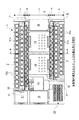
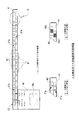
本発明が適用されたPLCの外観を示す平面図が図1に示されている。同図に示されるように、このPLC1のハウジングは、その平面において、先の従来例と同様に、入力端子台配置領域aと、入力端子シンボル配置領域bと、本体領域cと、出力端子シンボル配置領域dと、出力端子台配置領域eとに分割されている。
A plan view showing the appearance of a PLC to which the present invention is applied is shown in FIG. As shown in the figure, the housing of the
入力端子台配置領域aには、入力端子台2が配置される。この入力端子台2は、上段端子21aを1列に配列してなる上段入力端子列21と、下段端子22aを1列に配置してなる下段入力端子列22とを含んでいる。図から明らかなように、上段入力端子列21と下段入力端子列22とは2分の1ピッチ幅方向にずらした関係となっており、いわゆる千鳥状端子配列を有している。これは配線作業の容易化を図るためである。
The
同様にして、出力端子台配置領域eには出力端子台3が配置されている。この例にあっては、出力端子台3は、上段端子31aを1列に配列してなる上段出力端子列31と、下段端子32aを1列に配列してなる下段出力端子列32とを含んでいる。上段出力端子列31と下段出力端子列32とは、図から明らかなように、2分の1幅方向へずらした関係となっており、いわゆる千鳥状端子配列パターンを有している。
Similarly, the
入力端子シンボル配置領域bには、入力側配線表4が設けられている。後に詳細に説明するように、入力側配線表4は、透明な樹脂シートの上に印刷によって端子シンボルを描いたものであって、後述する光ガイドの上面に貼り付けられたものである。 An input side wiring table 4 is provided in the input terminal symbol arrangement area b. As will be described in detail later, the input-side wiring table 4 has terminal symbols drawn on a transparent resin sheet by printing, and is attached to the upper surface of a light guide to be described later.
同様にして、出力端子シンボル配置領域dにも、出力側配線表5が設けられている。この出力側配線表5にあっても、後に詳細に説明するように、透明な樹脂シートの表面に印刷によって端子シンボルを描いたものであり、後述する光ガイドの上面に貼り付けられている。 Similarly, the output side wiring table 5 is also provided in the output terminal symbol arrangement region d. Also in the output side wiring table 5, as will be described in detail later, terminal symbols are drawn on the surface of a transparent resin sheet by printing, and are pasted on the upper surface of a light guide to be described later.
その他、図1において、14はが運転状態表示部、15,16,19は付属品収納部、17はバッテリ収容部、18はボリューム等の操作機器収容部、21はアナログ入出力端子部である。 In addition, in FIG. 1, 14 is a driving | running state display part, 15,16,19 is an accessory storage part, 17 is a battery accommodating part, 18 is operation equipment accommodating parts, such as a volume, 21 is an analog input / output terminal part. .
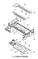
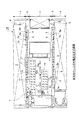
次に、PLCの構造を示す分解斜視図が図2に示されている。同図に示されるように、このPLCは、入力側光ガイド23、出力側光ガイド24、ハウジング本体25、回路基板26とを備えている。
Next, an exploded perspective view showing the structure of the PLC is shown in FIG. As shown in the figure, the PLC includes an input side
ハウジング本体25は、この例では入力端子台2および出力端子台3を取り外した状態とされており、その内部には回路基板26が装着される。回路基板26は、主回路を構成する3個のLSI26f,26g,26hを搭載する。また、回路基板26の一方の側縁部には、入力側上段LED26aと入力側下段LED26bが等ピッチで2列に搭載されると共に、他方の縁部には、出力側上段LED26cと出力側下段LED26dとが等ピッチで2列に配列される。後述するように、これらのLED26a〜26dからの光によって、表示シンボルが照明される。
In this example, the
なお、回路基板26上において、26eは7セグメント表示器であり、運転中の各種の動作を表示するために使用される。
On the
一方、入力側光ガイド23は、ハウジング上面と面一となる上面23cを有すると共に、その下面側からは、垂直方向に2列に並べて、上段ガイドピン23aと下段ガイドピン23bとが突出して形成されている。これらのガイドピン23a,23bは、ハウジング本体25の一側縁部に配列された挿通孔25aに挿入され、その先端は、回路基板26上に搭載された入力側上段LED26aおよび入力側下段LED26bに近接または接触して位置決めされる。一方、出力側光ガイド24も同様にして上面24cを有すると共に、その下面からは、上段ガイドピン24aと下段ガイドピン24bとが突出して形成される。これらの上段ガイドピン24aおよび下段ガイドピン24bは、ハウジング本体25の他方の側縁部に2列に形成された挿入孔25bに挿入され、その先端ないし下端は、回路基板26の他方の側縁部に配列された出力側上段LED26cおよび出力側下段LED26dに近接または接触して位置決めされる。
On the other hand, the input-side
そのため、回路基板26上のLED26a〜26dのいずれかが点灯すると、それらのLEDからの光は、該当するガイドピン23a,23b,24a,24bにより導かれて入力側光ガイド23の上面23cまたは入力側光ガイド24の上面24cへと到達する。すると、このLEDから導かれた光によって、入力側光ガイド23及び出力側光ガイド24の上面に貼り付けられた配線表4,5に描かれた端子シンボルが照明されて、明瞭に描き出されることとなる。
Therefore, when any one of the
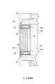
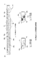
この端子シンボルの表示動作を、図3のA−A断面図、図4のB部拡大図、図5の入力側光ガイドの配線表の説明図、図6の出力側光ガイドの配線表の説明図を参照しながら以下に詳細に説明する。 This terminal symbol display operation is shown in the AA cross-sectional view of FIG. 3, an enlarged view of a portion B of FIG. 4, the explanatory diagram of the input side light guide wiring table of FIG. 5, and the output side light guide wiring table of FIG. This will be described in detail below with reference to the explanatory drawings.
図3に示されるように、回路基板26の表面に搭載された入力側上段LED26a,入力側下段LED26b,出力側上段LED26c,出力側下段LED26dからの光は、それぞれ下段光ガイドピン23b,上段光ガイドピン23a,上段光ガイドピン24a,下段光ガイドピン24bを通って、入力側光ガイド23および出力側光ガイド24の上面23c,24cへと放射される。
As shown in FIG. 3, the light from the input-side
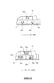
図5(a)に示されるように、入力光ガイドの上面には、入力側配線表4が貼り付けられている。この入力側配線表4は、入力端子台の端子配列にあわせて2列に分割され、各列はさらに個々の端子幅に対応して分割されて、上段個別領域41と下段個別領域42とに区画されている。上段個別領域41の中央部には端子シンボル27の1つである端子番号数字27aが描かれると共に、下段個別領域42の中央部には同様にして端子シンボル27の1つである端子番号数字27aが描かれている。
As shown in FIG. 5A, the input side wiring table 4 is attached to the upper surface of the input light guide. This input-side wiring table 4 is divided into two rows according to the terminal arrangement of the input terminal block, and each row is further divided in accordance with the individual terminal width, and is divided into an upper
図5(b)及び(c)のD部拡大図に示されるように、上段個別領域41の中央部には、光ガイドピンの出口に相当する透明窓が開口形成されており、この窓部が発光部41aとなる。同様にして、下段個別領域42の中央部にも、光ガイドピンの出口に相当する透明窓部が開口形成されており、この透明窓部が発光領域42aとなる。すなわち、上段個別領域41及び下段個別領域42は互いに密に隣接した細長長方形状の領域であるが、実際にはその中央部のみが光ガイドピンの出口に対応して長方形状に透明素材で形成されており、これにより該当するLEDが発光すると、その光がガイドピンを通して、それら領域41,42の中央部に設けられた矩形の透明窓部に導かれ、その結果そこに描かれた端子番号数字27aは、その背後からLEDの光で照明され、端子番号数字27aが明瞭に描き出されるのである。なお、図5(a)において、14は表示部、14aは7セグメント表示領域であり、ハウジング内部に収容された7セグメント表示器26eからの光がこの表示領域14aを通してハウジング上面から見えることとなる。
As shown in the enlarged view of the D part in FIGS. 5B and 5C, a transparent window corresponding to the exit of the light guide pin is formed in the center of the upper
次に、図6(a)に示されるように、出力側光ガイド24の上面にも配線表5が貼り付けられている。この配線表5も、透明な樹脂シートに、印刷技術を用いて、上段個別領域51及び下段個別領域52を描くと共に、それら領域の中央部には同様に印刷技術を用いて、端子番号数字28aが描かれている。
Next, as shown in FIG. 6A, the wiring table 5 is also attached to the upper surface of the output side
また、図6(b)及び図6(c)のC部拡大図に示されるように、各個別領域51,52のほぼ中央部には、矩形の透明部分が設けられており、この透明部分は光ガイドピンの出口に対応している。そのため、回路基板上のLEDが点灯すると、その光が光ガイドピンを通じて光ガイド24の上面へと導かれ、そこに描かれた端子番号数字をその背後から照明して、明瞭に描き出すこととなるのである。その結果図64に示されるCB部拡大図から明らかなように、LEDが光っていない状態にあっては、同図(ba)に示されるように、上段個別領域51及び下段個別領域52のそれぞれの中央部に描かれた端子番号数字28aは、特に顕著に照明されることはないのに対し、同図(cb)に示されるように、LEDが光っている状態にあっては、端子番号数字28aは、その背後からLEDの光を受けて発光部51aに示されるように矩形領域が発光し、その明るいバックグラウンドの中に濃色の数字部分が明瞭に描き出されることとなるのである。
Further, as shown in the enlarged view of part C in FIGS. 6B and 6C, a rectangular transparent portion is provided in the substantially central portion of each
以上説明したように、この実施形態のPLC1によれば、外部配線を結線するための端子(上段端子21a,下段端子22a,上段端子31a,下段端子32a)を複数配列してなる端子台(入力端子台2,出力端子台3)と、端子台を構成する各端子を識別するためのシンボル(例えば、入力端子番号数字27a,出力端子番号数字28a)を、端子台上の端子配列に整合するように、端子台(入力端子台2,出力端子台3)に隣接して配列してなる端子シンボル列(27a,27b,28a,28b,28c28a・・・28a,28a)と、端子台を構成する各端子の信号状態に応じてそれぞれ点消灯する複数の表示灯(発光領域41a,42a,51a,52a)とを有し、かつ端子シンボル列を構成する個々の端子シンボル(27a,28a)と表示灯列を構成する個々の表示灯(発光領域41a,42a,51a,52a)とは、対応するもの同士において、位置的に重なるように配置されているのである。
As described above, according to the
そのため、図1から明らかなように、本発明によれば、いずれかの発光領域が発光して、その中央部に描かれた端子番号数字が明瞭に描き出されれば、直ちにその発光部の真上もしくは真下に位置する端子の配線にそのような信号が出力され又は到来したことを一目瞭然で把握することができ、メンテナンス作業やトラブルシューティングなどの際に、その作業性が著しく改善されるのである。 Therefore, as is apparent from FIG. 1, according to the present invention, if any one of the light emitting regions emits light and the terminal number number drawn in the central portion is clearly drawn, immediately above the light emitting portion. Alternatively, it is possible to grasp at a glance that such a signal has been output or arrived at the wiring of the terminal located directly below, and the workability is remarkably improved during maintenance work or troubleshooting.
なお、以上の実施形態においては、本発明を入出力ユニット一体型のPLC(パッケージ型PLCと呼ばれることもある)に適用したが、本発明の適用はこれに限られるものではなく、ビルディング・ブロックタイプのPLCにおける入力ユニット、出力ユニット、入出力ユニット、さらには通信を介してマスタユニットと接続されたリモート入力ユニット、リモート出力ユニット、リモート入出力ユニットなどにも同様な適用が可能である。つまり、本発明は、PLCシステムを構成する場合において、外部機器と接続するための信号線(外部配線)を結線するための端子を複数配列してなる端子台を備えた装置にも適用が可能である。 In the above embodiment, the present invention is applied to an input / output unit integrated PLC (sometimes referred to as a package type PLC), but the application of the present invention is not limited to this. The same application can be applied to an input unit, an output unit, an input / output unit, and a remote input unit, a remote output unit, a remote input / output unit and the like connected to the master unit via communication in a type PLC. In other words, the present invention can be applied to an apparatus having a terminal block in which a plurality of terminals for connecting signal lines (external wiring) for connecting to external devices are arranged in the case of configuring a PLC system. It is.
本発明のプログラマブル・コントローラの端子台装置によれば、端子シンボル列を構成する個々の端子シンボルと表示灯列を構成する個々の表示灯とは、対応するもの同士において、位置的に重なるように配置されており、しかも端子台を構成する各端子を識別するためのシンボルは、端子台上の端子配列に整合するように、端子台に隣接して配列されるものであるから、いずれかの端子シンボルと対をなす表示灯が点灯または消灯すれば、その表示灯と対をなす端子シンボルとの位置関係に基づいて、該当する配線が接続された端子を直ちに判別することができ、トラブルシューティングやメンテナンスの際における作業性が良好なものとなる。 According to the terminal block device of the programmable controller of the present invention, the individual terminal symbols constituting the terminal symbol row and the individual indicator lights constituting the indicator lamp row are positioned so as to overlap each other. The symbols for identifying each terminal that is arranged and that constitutes the terminal block are arranged adjacent to the terminal block so as to match the terminal arrangement on the terminal block. If the indicator light that is paired with the terminal symbol is turned on or off, the terminal to which the corresponding wiring is connected can be immediately identified based on the positional relationship between the indicator light and the terminal symbol that makes a pair, and troubleshooting And workability during maintenance is improved.
1 PLC
2 入力端子台
3 出力端子台
4 入力側配線表
5 出力側配線表
14 運転表示部
15,16,19 付属品収納部
17 バッテリ収容部
18 外部操作機器収容部
21 上段入力端子列
22 下段入力端子列
21a 上段端子
22a 下段端子
23 入力側光ガイド
23a 上段ガイドピン
23b 下段ガイドピン
23c 上面
24 出力側光ガイド
24a 上段ガイドピン
24b 下段ガイドピン
24c 上面
25a 挿通孔
25b 挿通孔
26 回路基板
26a 入力側上段LED
26b 入力側下段LED
26c 出力側上段LED
26d 出力側下段LED
26e 7セグメント表示器
26f,26g,26h 主回路を構成するLSI
27 端子シンボル
27a 端子番号数字
28 端子シンボル
28a 端子番号数字
31 上段出力端子列
31a 上段端子
32 下段出力端子列
32a 下段端子
41 上段個別領域
41a 発光領域
42 下段個別領域
42a 発光領域
51 上段個別領域
52 下段個別領域
51 上段個別領域
52 下段個別領域
51a 発光領域
52a 発光領域
1 PLC
2 Input
26b Input side lower LED
26c Output side upper LED
26d Output side lower LED
26e 7-
27
Claims (10)
端子台を構成する各端子を識別するためのシンボルを、端子台上の端子配列に整合するように、端子台に隣接して配列してなる端子シンボル列と、
端子台を構成する各端子の信号状態に応じてそれぞれ点消灯する複数の表示灯を配列してなる表示灯列とを有し、かつ
端子シンボル列を構成する個々の端子シンボルと表示灯列を構成する個々の表示灯とは、対応するもの同士において、位置的に重なるように配置されている、
ことを特徴とするプログラマブル・コントローラ。 A terminal block in which a plurality of terminals for connecting external wiring are arranged;
A symbol string for identifying each terminal constituting the terminal block, a terminal symbol string arranged adjacent to the terminal block so as to match the terminal arrangement on the terminal block, and
A display lamp array in which a plurality of indicator lamps are turned on and off according to the signal state of each terminal constituting the terminal block, and each terminal symbol and display lamp array constituting the terminal symbol array The individual indicator lamps that are configured are arranged so as to overlap each other in a corresponding manner.
A programmable controller characterized by that.
ハウジング内に収容された回路基板と、
回路基板上に搭載されLED列と、
一端が回路基板上のLED列のそれぞれに位置し、他端が端子台に隣接して配列された端子シンボル列に位置する複数の光ガイド部を有する光ガイドとを有する、
ことを特徴とする請求項1に記載のプログラマブル・コントローラ。 A housing having a terminal block;
A circuit board housed in the housing;
An LED array mounted on a circuit board;
A light guide having a plurality of light guide portions located at one end of each of the LED rows on the circuit board and at the other end of the terminal symbol row arranged adjacent to the terminal block;
The programmable controller according to claim 1.
ことを特徴とする請求項2に記載のプログラマブル・コントローラ。 The circuit board is a main circuit board on which an LSI corresponding to the main circuit is mounted, and the LED row is arranged along an edge of the main circuit board.
The programmable controller according to claim 2.
ことを特徴とする請求項3に記載のプログラマブル・コントローラ。 Each LED constituting the LED row is arranged on a circuit board corresponding to a position immediately below each terminal symbol constituting the terminal symbol row, and each light guide portion connecting each LED and each terminal symbol is a linear light guide pin. ing,
The programmable controller according to claim 3.
ことを特徴とする請求項2に記載のプログラマブル・コントローラ。 A transparent window is formed at the end of the light guide opposite to the LED, and a transparent sheet on which a terminal symbol is drawn is disposed in the transparent window, and the terminal symbol on the transparent sheet is emitted from the LED. Illuminated by the light guided by the guide part,
The programmable controller according to claim 2.
ことを特徴とする請求項2に記載のプログラマブル・コントローラ。 The terminal symbol is a terminal number,
The programmable controller according to claim 2.
ことを特徴とする請求項2に記載のプログラマブル・コントローラ。 Configured as a programmable controller having an input terminal block and / or an output terminal block,
The programmable controller according to claim 2.
ことを特徴とする請求項1〜7のいずれかに記載のプログラマブル・コントローラ。 The indicator lamp of the terminal symbol corresponding to each terminal constituting the input terminal block is directly driven to light in conjunction with the input signal to the terminal without going through the input refresh process of the programmable controller.
The programmable controller according to any one of claims 1 to 7.
ことを特徴とする請求項1〜7のいずれかに記載のプログラマブル・コントローラ。 The indicator light of the terminal symbol corresponding to each terminal constituting the output terminal block is driven to light through the output refresh process of the programmable controller.
The programmable controller according to any one of claims 1 to 7.
ことを特徴とする請求項1〜9のいずれかに記載のプログラマブル・コントローラ。 The terminal block has an upper stage terminal row and a lower end terminal row arranged with a ½ pitch shift from each other, and the terminal symbol row and the indicator lamp row are arranged in a staggered manner adjacent to the terminal block.
The programmable controller according to any one of claims 1 to 9.
Priority Applications (5)
| Application Number | Priority Date | Filing Date | Title |
|---|---|---|---|
| JP2006075334A JP2006309727A (en) | 2005-03-31 | 2006-03-17 | Programmable controller |
| DE200620005168 DE202006005168U1 (en) | 2005-03-31 | 2006-03-30 | Programmable controller |
| ES200600764U ES1063066Y (en) | 2005-03-31 | 2006-03-31 | PROGRAMMABLE CONTROLLER |
| ITTO20060044 ITTO20060044U1 (en) | 2005-03-31 | 2006-03-31 | PROGRAMMABLE CONTROLLER, IN PARTICULAR PLC, EQUIPPED WITH A STATUS DISPLAY FUNCTION |
| FR0602836A FR2883991B3 (en) | 2005-03-31 | 2006-03-31 | PROGRAMMABLE CONTROLLER. |
Applications Claiming Priority (2)
| Application Number | Priority Date | Filing Date | Title |
|---|---|---|---|
| JP2005105341 | 2005-03-31 | ||
| JP2006075334A JP2006309727A (en) | 2005-03-31 | 2006-03-17 | Programmable controller |
Publications (1)
| Publication Number | Publication Date |
|---|---|
| JP2006309727A true JP2006309727A (en) | 2006-11-09 |
Family
ID=36972828
Family Applications (1)
| Application Number | Title | Priority Date | Filing Date |
|---|---|---|---|
| JP2006075334A Pending JP2006309727A (en) | 2005-03-31 | 2006-03-17 | Programmable controller |
Country Status (5)
| Country | Link |
|---|---|
| JP (1) | JP2006309727A (en) |
| DE (1) | DE202006005168U1 (en) |
| ES (1) | ES1063066Y (en) |
| FR (1) | FR2883991B3 (en) |
| IT (1) | ITTO20060044U1 (en) |
Cited By (6)
| Publication number | Priority date | Publication date | Assignee | Title |
|---|---|---|---|---|
| JP2009157872A (en) * | 2007-12-28 | 2009-07-16 | Koyo Electronics Ind Co Ltd | Device with input and output function such as programmable controller |
| JP2009301147A (en) * | 2008-06-10 | 2009-12-24 | Daiwa House Industry Co Ltd | Contact input/output control device |
| JP2012226631A (en) * | 2011-04-21 | 2012-11-15 | Mitsubishi Electric Corp | Unit type programmable controller |
| WO2018061505A1 (en) * | 2016-09-30 | 2018-04-05 | オムロン株式会社 | Industrial electronic apparatus |
| JP7078965B1 (en) * | 2021-01-06 | 2022-06-01 | 株式会社ラプラス・システム | Terminal block type unit and monitoring system using it |
| WO2022149348A1 (en) * | 2021-01-06 | 2022-07-14 | 株式会社ラプラス・システム | Terminal block unit and monitoring system using same |
Families Citing this family (1)
| Publication number | Priority date | Publication date | Assignee | Title |
|---|---|---|---|---|
| US9055688B2 (en) * | 2010-08-20 | 2015-06-09 | Rockwell Automation Technologies, Inc. | Input/output circuits having status indicators aligned with respective terminals |
-
2006
- 2006-03-17 JP JP2006075334A patent/JP2006309727A/en active Pending
- 2006-03-30 DE DE200620005168 patent/DE202006005168U1/en not_active Expired - Lifetime
- 2006-03-31 FR FR0602836A patent/FR2883991B3/en not_active Expired - Lifetime
- 2006-03-31 IT ITTO20060044 patent/ITTO20060044U1/en unknown
- 2006-03-31 ES ES200600764U patent/ES1063066Y/en not_active Expired - Fee Related
Cited By (7)
| Publication number | Priority date | Publication date | Assignee | Title |
|---|---|---|---|---|
| JP2009157872A (en) * | 2007-12-28 | 2009-07-16 | Koyo Electronics Ind Co Ltd | Device with input and output function such as programmable controller |
| JP2009301147A (en) * | 2008-06-10 | 2009-12-24 | Daiwa House Industry Co Ltd | Contact input/output control device |
| JP2012226631A (en) * | 2011-04-21 | 2012-11-15 | Mitsubishi Electric Corp | Unit type programmable controller |
| WO2018061505A1 (en) * | 2016-09-30 | 2018-04-05 | オムロン株式会社 | Industrial electronic apparatus |
| US10834840B2 (en) | 2016-09-30 | 2020-11-10 | Omron Corporation | Industrial electronic apparatus |
| JP7078965B1 (en) * | 2021-01-06 | 2022-06-01 | 株式会社ラプラス・システム | Terminal block type unit and monitoring system using it |
| WO2022149348A1 (en) * | 2021-01-06 | 2022-07-14 | 株式会社ラプラス・システム | Terminal block unit and monitoring system using same |
Also Published As
| Publication number | Publication date |
|---|---|
| ITTO20060044U1 (en) | 2006-10-01 |
| FR2883991B3 (en) | 2007-04-13 |
| DE202006005168U1 (en) | 2006-09-07 |
| FR2883991A3 (en) | 2006-10-06 |
| ES1063066Y (en) | 2007-01-01 |
| ES1063066U (en) | 2006-10-01 |
Similar Documents
| Publication | Publication Date | Title |
|---|---|---|
| JP2006309727A (en) | Programmable controller | |
| US7194183B2 (en) | Modular receptacle assembly and interface with integral optical indication | |
| CN106664813B (en) | Electronic user interface with separate control circuit board and household appliance with such user interface | |
| JP5449332B2 (en) | Operating device having light guide wire bundle | |
| JP5875364B2 (en) | Switch unit and vending machine equipped with the same | |
| KR19980701904A (en) | Display device for programmable logic controller | |
| JP6315261B2 (en) | Display device | |
| JP4577555B2 (en) | Light guide member and display using the same | |
| JP5063954B2 (en) | Lighting device and vending machine equipped with the same | |
| JP6489546B2 (en) | Illuminated display device | |
| JP5191728B2 (en) | Pushbutton switch device and vending machine equipped with the same | |
| US11624485B1 (en) | Illumination set and alphabet lamp | |
| JP5823748B2 (en) | Pedestrian signal unit | |
| JP5724112B2 (en) | Program verification device for I / O devices | |
| JP2006261036A (en) | Lighting structure | |
| JP3995303B2 (en) | Switch device for vending machine | |
| KR200404839Y1 (en) | Bus Guide Displaying Panel | |
| US7325945B2 (en) | Electronic device having light emitting units thereon in high density | |
| JP2007219464A (en) | Electronic apparatus with display | |
| JP2017117250A (en) | Sensor device, sensor unit, article selection device, article selection unit, and vending machine | |
| JP2023139573A (en) | Operation display device and electronic musical instrument | |
| JP2011052972A (en) | Meter device | |
| CN104076709B (en) | Programmable Logic Controller | |
| JP2015225742A (en) | Wire harness assembly support apparatus | |
| KR20110129336A (en) | Touch-type transparent keyboard |
Legal Events
| Date | Code | Title | Description |
|---|---|---|---|
| A621 | Written request for application examination |
Free format text: JAPANESE INTERMEDIATE CODE: A621 Effective date: 20070315 |
|
| A871 | Explanation of circumstances concerning accelerated examination |
Free format text: JAPANESE INTERMEDIATE CODE: A871 Effective date: 20080415 |
|
| A975 | Report on accelerated examination |
Free format text: JAPANESE INTERMEDIATE CODE: A971005 Effective date: 20080716 |
|
| A131 | Notification of reasons for refusal |
Free format text: JAPANESE INTERMEDIATE CODE: A131 Effective date: 20080807 |
|
| A521 | Written amendment |
Free format text: JAPANESE INTERMEDIATE CODE: A523 Effective date: 20081006 |
|
| A02 | Decision of refusal |
Free format text: JAPANESE INTERMEDIATE CODE: A02 Effective date: 20081119 |
|
| A521 | Written amendment |
Free format text: JAPANESE INTERMEDIATE CODE: A523 Effective date: 20090114 |
|
| A911 | Transfer of reconsideration by examiner before appeal (zenchi) |
Free format text: JAPANESE INTERMEDIATE CODE: A911 Effective date: 20090126 |
|
| A912 | Removal of reconsideration by examiner before appeal (zenchi) |
Free format text: JAPANESE INTERMEDIATE CODE: A912 Effective date: 20090515 |