JP2006308992A - Projection display device and projection optical system - Google Patents
Projection display device and projection optical system Download PDFInfo
- Publication number
- JP2006308992A JP2006308992A JP2005133381A JP2005133381A JP2006308992A JP 2006308992 A JP2006308992 A JP 2006308992A JP 2005133381 A JP2005133381 A JP 2005133381A JP 2005133381 A JP2005133381 A JP 2005133381A JP 2006308992 A JP2006308992 A JP 2006308992A
- Authority
- JP
- Japan
- Prior art keywords
- projection
- light
- diaphragm
- optical system
- display device
- Prior art date
- Legal status (The legal status is an assumption and is not a legal conclusion. Google has not performed a legal analysis and makes no representation as to the accuracy of the status listed.)
- Pending
Links
Images


Landscapes
- Projection Apparatus (AREA)
- Surface Treatment Of Optical Elements (AREA)
Abstract
Description
本発明は、反射型ライトバルブを用いた投写型表示装置及び投写光学系に関する。 The present invention relates to a projection display device and a projection optical system using a reflective light valve.
大画面映像を得る方法として、ライトバルブ上に映像信号に応じた画像を形成し、その画像に光を照射して形成された光学像を投写レンズにてスクリーン上に拡大投写する方法が従来から良く知られている。かかるライトバルブとして、映像信号に応じて光の進行方向を制御することによって光学像を形成する反射型ライトバルブを用いた場合には、光利用効率の高い高輝度の投写画像を表示することができる。 As a method for obtaining a large screen image, there has conventionally been a method in which an image corresponding to a video signal is formed on a light valve, and an optical image formed by irradiating the image with light is enlarged and projected on a screen by a projection lens. Well known. As such a light valve, when a reflection type light valve that forms an optical image by controlling the traveling direction of light according to a video signal, a high-luminance projection image with high light utilization efficiency can be displayed. it can.
前記のごとき反射型ライトバルブとしては、近年、デジタル・マイクロミラー・デバイス(Digital Micromirror Device、以下、DMDという)が特に注目されている。DMDはシリコン基板上に多数の微少な反射ミラー(以下、微少ミラーという)が2次元的に配置され、各微少ミラーが画素を構成しており、これら各微少ミラーは±θ度(通常、θは約10)の範囲でシーソーのように可動するように構成されている。DMDは、映像信号に応じて、各微少ミラーを+θ度又は−θ度傾かせることで光線の出射方向を制御し、光学像を形成するものである。 In recent years, a digital micromirror device (hereinafter referred to as DMD) has attracted particular attention as the reflective light valve as described above. In DMD, a large number of minute reflecting mirrors (hereinafter referred to as minute mirrors) are two-dimensionally arranged on a silicon substrate, and each minute mirror constitutes a pixel, and each of these minute mirrors is ± θ degrees (usually θ Is configured to move like a seesaw within a range of about 10). The DMD forms an optical image by controlling the light emission direction by tilting each micromirror by + θ degrees or −θ degrees in accordance with a video signal.
従来より、例えば前記DMDなどの反射型ライトバルブを用いた各種投写型表示装置の開発が進められてきている。このような従来の投写型表示装置の一例を図8及び図11の概略水平断面図に示す。照明光を反射型ライトバルブに導き、形成された光学像を投写光学系に入力させる光学ユニットとして、図8の投写型表示装置では全反射プリズム25A、25Bが用いられ、図11の投写型表示装置では凸レンズ55が用いられている。いずれの投写型表示装置の場合も光学ユニット以外は概ね同様の構成を有するので、代表して、光学ユニットとして全反射プリズム25A、25Bを用いた図8の投写型表示装置について、投写光学系におけるの投写レンズの光軸の延長線上に位置する反射型ライトバルブに、照明光学系からの照明光が入射する動作を以下に説明する。
2. Description of the Related Art Conventionally, various types of projection display devices using a reflective light valve such as the DMD have been developed. An example of such a conventional projection display device is shown in the schematic horizontal sectional views of FIGS. As the optical unit for guiding the illumination light to the reflective light valve and inputting the formed optical image to the projection optical system, the
光源としてのランプ21から照射される放射光を集光して被照明面(反射型ライトバルブ26)を照明する照明光学系30は、ランプ21、凹面鏡22、断面が反射型ライトバルブ26の有効表示領域と略同じアスペクト比で、例えば四角柱状のロッドプリズム23及びコンデンサーレンズ24によって構成されている。凹面鏡22は、反射面の断面形状が楕円形をなし、第1焦点と第2焦点とを有する。ランプ21の発光体の中心が、凹面鏡22の第1焦点付近に位置するように配置され、ロッドプリズム23の光入射口35が、凹面鏡22の第2焦点付近に位置するように配置されている。また凹面鏡22は、通常ガラス製基材の内面に赤外光を透過させて可視光を反射させる光学多層膜を形成したものである。
The illumination
ランプ21から照射される放射光は凹面鏡22により反射及び集光され、凹面鏡22の第2焦点にランプ21の発光体像を形成する。ランプ21の発光体像は光軸に近い中心付近が最も明るく、周辺ほど急激に暗くなる傾向があるため、輝度に不均一性が残る。この問題は、凹面鏡22の第2焦点付近にロッドプリズム23の光入射口35を配置し、ロッドプリズム23の内側面で照明光31を多重反射させて輝度の均一化を図り、ロッドプリズム23の光出射口36を2次光源とすることによって解決される。そしてこの2次光源から、以降のコンデンサーレンズ24、さらには光学ユニットである全反射プリズム25Aの面25aから全反射プリズム25Bの面25bを介し、カバーガラス27を通して反射型ライトバルブ26を照明し、照明光31の均一性を確保することができる。特に反射型ライトバルブ26としてDMDを使用した場合、DMDの微少ミラーに入射した照明光31の反射光の光束は、微少ミラーがON信号時には投写光学系28の投写レンズ29に入射する入射光32となり、逆にOFF信号時には投写レンズ29に入射しない方向に進行する非入射光33となる。このようにON信号時の光とOFF信号時の光との時間配分を映像信号に応じて制御することにより、スクリーン上に投写すべき画像を形成させる。
The radiated light emitted from the
このように光学ユニットとして2枚以上のプリズムを用い、これとDMDなどの反射型ライトバルブとを組み合わせ、さらに照明光学系及び投写光学系を備えた投写型表示装置が、従来より種々提案されてきている(例えば特許文献1参照)。 As described above, various types of projection display devices that use two or more prisms as an optical unit, combine this with a reflective light valve such as a DMD, and further include an illumination optical system and a projection optical system have been proposed. (For example, refer to Patent Document 1).
しかしながら、このような投写型表示装置では、図8に示すように、反射型ライトバルブ26を照明した照明光31の一部がDMDの微少ミラーに到達する前にカバーガラス27と空気との界面で反射する。これは不要反射光50として進行し(斜線部)、その一部は投写光学系28内の投写レンズ29に入射する。この不要反射光50は、微少ミラーのON信号、OFF信号に関係なく投写レンズ29に入射するため、特にOFF信号時に、投写画像の黒表示の品質に著しく悪影響を及ぼし、コントラストを低下させる要因となるといった問題があった。
However, in such a projection display device, as shown in FIG. 8, the interface between the
そこで前記不要反射光を抑制する方法として、投写レンズの入射瞳の近傍に光軸に対して回転対称の絞りを配置し、この絞りの径を小さくすることが考えられるが、かかる方法では、投写画像に寄与する有効な入射光まで抑制されてしまう。これを図面を用いて説明する。図9(a)に、円39aで示された絞り34の本来の開口37aが示されている。この絞り34における、反射型ライトバルブ側の面に生じた、カバーガラスと空気との界面での照明光の反射による不要反射光が集合した領域(以下、不要反射光領域という)を、図9(b)に示す(斜線部、符号51)。かかる不要反射光領域51に起因したコントラストの低下や、本来必要な画像とは無関係で、ある程度の明るさを有する不要な投写画像(以下、ゴーストという)の形成による投写画像への悪影響を取り除くためには、例えば円39aで示された絞り34の本来の開口37aを、図9(c)に示すように、円39bで示された開口37bのように小さくし、不要反射光領域51が投写レンズのスクリーン側に到達しないようにすることが考えられる。
Therefore, as a method of suppressing the unnecessary reflected light, it is conceivable to arrange a stop that is rotationally symmetric with respect to the optical axis in the vicinity of the entrance pupil of the projection lens, and to reduce the diameter of this stop. Even effective incident light that contributes to the image is suppressed. This will be described with reference to the drawings. FIG. 9A shows the
しかしながら、図9(c)から明らかなように、円39bで示された開口37bの径は、円39aで示された本来の開口37aの径よりも大幅に小さくなるため、投写画像に寄与すべき有効な入射光も遮光され、投写画像の明るさが大幅に低減してしまう。
However, as is clear from FIG. 9C, the diameter of the opening 37b indicated by the
そこで前記問題を解決すべく、反射型ライトバルブの前面で反射された不要反射光がスクリーン上へ投写されるのを抑制するために、絞りの開口の重心を、投写レンズの光軸に対して、偏心して配置するとともに変位可能とした投写型表示装置が提案されている(例えば特許文献2参照)。かかる投写型表示装置によれば、投写画像に寄与すべき有効な入射光の遮光をできる限り抑制し、投写画像の明るさをそれ程低減させることなく、コントラスト性能をある程度向上させることが可能である。
しかしながら、前記のごとき、開口の重心が投写レンズの光軸に対して偏心しているか又は開口が投写レンズの光軸に対して非対称な形状である絞り(以下、非対称絞りという)は、不要反射光だけではなく、やはり投写画像に寄与すべき非常に明るい入射光も一部遮光してしまうため、該非対称絞りの不要反射光を遮光する部分の表面は、かかる投写画像に寄与すべき強い光で照射されている。そこでこの非対称絞りの表面で不要反射光や投写画像に寄与すべき一部の入射光が反射するのを抑制するために、該表面には例えば艶消し黒色塗装や黒色アルマイト処理を施すことが試みられているものの、図10に示すように、相当量の光が非対称絞り34の表面で反射して投写光学系28内を反射型ライトバルブ26の方向に戻り、その一部は投写レンズのレンズ面54で再度反射してスクリーン上に投写される光52となって投写画像のコントラストを低下させてしまう。また非対称絞り34の表面で反射して反射型ライトバルブ26の方向に戻る別の光53は、一部反射型ライトバルブ26にまで到達し、スクリーン上にゴーストが形成される原因となる。
However, as described above, an aperture whose center of gravity of the aperture is decentered with respect to the optical axis of the projection lens or whose aperture is asymmetric with respect to the optical axis of the projection lens (hereinafter referred to as an asymmetric aperture) is not necessary reflected light. Not only that, but also part of the very bright incident light that should contribute to the projected image, the surface of the portion of the asymmetric aperture that blocks unwanted reflected light is strong light that should contribute to the projected image. Irradiated. Therefore, in order to suppress reflection of unnecessary reflected light and a part of incident light that should contribute to the projected image on the surface of the asymmetric diaphragm, for example, a matte black coating or black alumite treatment is applied to the surface. However, as shown in FIG. 10, a considerable amount of light is reflected by the surface of the
このように、投写光学系に非対称絞りを備えた従来の投写型表示装置では、該非対称絞りの表面で反射した光がコントラスト低下やゴースト形成の原因となり、やはり目的とする投写画像の品質が低下してしまう。 As described above, in a conventional projection display apparatus having an asymmetric diaphragm in the projection optical system, the light reflected by the surface of the asymmetric diaphragm causes a decrease in contrast and ghost formation, which also degrades the quality of the target projection image. Resulting in.
したがって、明るさの低減を最小限に留めながら、コントラストの低下やゴーストの形成を極力抑制し、高品質の投写画像を形成することができる投写型表示装置を提供することを課題とする。 Accordingly, it is an object of the present invention to provide a projection display device capable of forming a high-quality projection image while minimizing the reduction in contrast and the formation of ghosts while minimizing the reduction in brightness.
本発明は前記背景技術に鑑みてなされたものであり、
(イ)光源からの放射光を集光して反射型ライトバルブを照明する照明光学系と、照明光学系からの照明光を反射型ライトバルブに導く光学ユニットと、導かれた照明光を反射して光学像を形成する反射型ライトバルブと、反射型ライトバルブが形成した光学像である投写光を投写する投写光学系とを備えた投写型表示装置であって、前記投写光学系内の、投写光の一部を遮光する絞りの開口が、その重心が投写レンズの光軸に対して偏心しているか又は投写レンズの光軸に対して非対称な形状であり、前記絞りが、その反射型ライトバルブ側の面の少なくとも一部に、所定の形状を有する構造単位が投写光の最短波長よりも小さいピッチで周期的にアレイ状に配列された反射防止構造体と、投写光を吸収可能な材料とを有することを特徴とする投写型表示装置、並びに
(ロ)ライトバルブで形成された光学像である投写光を投写する投写光学系であって、前記投写光の一部を遮光する絞りの開口が、その重心が投写レンズの光軸に対して偏心しているか又は投写レンズの光軸に対して非対称な形状であり、前記絞りが、そのライトバルブ側の面の少なくとも一部に、所定の形状を有する構造単位が投写光の最短波長よりも小さいピッチで周期的にアレイ状に配列された反射防止構造体と、投写光を吸収可能な材料とを有することを特徴とする投写光学系
に関する。
The present invention has been made in view of the background art,
(B) An illumination optical system for condensing the radiated light from the light source to illuminate the reflective light valve, an optical unit for guiding the illumination light from the illumination optical system to the reflective light valve, and reflecting the guided illumination light A projection type display apparatus comprising: a reflection type light valve that forms an optical image; and a projection optical system that projects projection light that is an optical image formed by the reflection type light valve. The aperture of the aperture that blocks part of the projection light has a center of gravity that is decentered with respect to the optical axis of the projection lens or is asymmetric with respect to the optical axis of the projection lens, and the aperture is a reflection type thereof An antireflection structure in which structural units having a predetermined shape are periodically arranged in an array at a pitch smaller than the shortest wavelength of projection light on at least a part of the light valve side surface, and can absorb projection light Characterized by having material And (b) a projection optical system that projects projection light that is an optical image formed by a light valve, and the aperture of a diaphragm that blocks part of the projection light projects from the center of gravity. A structural unit that is decentered with respect to the optical axis of the lens or is asymmetric with respect to the optical axis of the projection lens, and the diaphragm has a predetermined shape projected on at least a part of the surface on the light valve side. The present invention relates to a projection optical system comprising an antireflection structure periodically arranged in an array at a pitch smaller than the shortest wavelength of light and a material capable of absorbing projection light.
本発明の投写型表示装置及び投写光学系により、明るさの低減が最小限に留められ、なおかつコントラストの低下やゴーストの形成が極力抑制された、高品質の投写画像が提供され得る。 With the projection display device and the projection optical system of the present invention, it is possible to provide a high-quality projection image in which the reduction in brightness is minimized and the reduction in contrast and the formation of ghosts are suppressed as much as possible.
(第1の実施形態)
本発明の第1の実施形態に係る投写型表示装置は、前記したように、
光源からの放射光を集光して反射型ライトバルブを照明する照明光学系、
照明光学系からの照明光を反射型ライトバルブに導く光学ユニット、
導かれた照明光を反射して光学像を形成する反射型ライトバルブ、及び
反射型ライトバルブで形成された光学像である投写光を投写する投写光学系
を備えている。そして本投写型表示装置における大きな特徴の1つは、前記投写光学系内の、投写光の一部を遮光する
絞り
の開口が、その重心が投写レンズの光軸に対して偏心しているか又は投写レンズの光軸に対して非対称な形状であり、前記絞りが、その反射型ライトバルブ側の面の少なくとも一部に、
所定の形状を有する構造単位が投写光の最短波長よりも小さいピッチで周期的にアレイ状に配列された反射防止構造体、及び
投写光を吸収可能な材料
を有することである。
(First embodiment)
The projection display device according to the first embodiment of the present invention, as described above,
An illumination optical system that illuminates the reflective light valve by collecting the emitted light from the light source,
An optical unit that guides the illumination light from the illumination optical system to the reflective light valve,
A reflection type light valve that reflects the guided illumination light to form an optical image, and a projection optical system that projects projection light that is an optical image formed by the reflection type light valve are provided. One of the major features of the present projection display device is that the aperture of the diaphragm that blocks part of the projection light in the projection optical system has its center of gravity decentered with respect to the optical axis of the projection lens. It has an asymmetric shape with respect to the optical axis of the lens, and the diaphragm is formed on at least a part of the reflective light valve side surface.
The structural unit having a predetermined shape has an antireflection structure in which the structural units are periodically arranged in an array at a pitch smaller than the shortest wavelength of the projection light, and a material capable of absorbing the projection light.
以下、図面を用いて前記投写型表示装置について詳細に説明する。
図1は、本発明に係る投写型表示装置の第1の実施形態を示す概略水平断面図である。かかる投写型表示装置には、光源としてのランプ1から照射される放射光を集光して、被照明面である反射型ライトバルブ6を照明する照明光学系10が配置されている。本発明の投写型表示装置に用いられる照明光学系には、少なくとも光源及びロッドプリズムが備えられるが、例えば図1に示す照明光学系10は、ランプ1、凹面鏡2、ロッドプリズム3及びコンデンサーレンズ4によって構成されている。該凹面鏡2は、反射面の断面形状が楕円形をなし、第1焦点と第2焦点とを有する。ランプ1の発光体の中心が、凹面鏡2の第1焦点付近に位置するように配置され、ロッドプリズム3の光入射口15が、凹面鏡2の第2焦点付近に位置するように配置されている。
Hereinafter, the projection display device will be described in detail with reference to the drawings.
FIG. 1 is a schematic horizontal sectional view showing a first embodiment of a projection display apparatus according to the present invention. In such a projection display device, an illumination
凹面鏡2は、例えばガラス製基材の内面に赤外光を透過させて可視光を反射させる光学多層膜を形成したものである。またロッドプリズム3は、その断面が反射型ライトバルブ6の有効表示領域と略同じアスペクト比であり、例えば内面に鏡を貼り合わせた四角柱プリズムやガラス製四角柱プリズムである。かかるロッドプリズム3の内部を通った光は略全反射して進むので、反射損失が殆どないという利点がある。
The concave mirror 2 is formed, for example, by forming an optical multilayer film that transmits infrared light and reflects visible light on the inner surface of a glass substrate. The
まずランプ1から照射される放射光は凹面鏡2により反射及び集光され、凹面鏡2の第2焦点にランプ1の発光体像を形成する。ランプ1の発光体像は光軸に近い中心付近が最も明るく、周辺ほど急激に暗くなる傾向があるため、輝度に不均一性が残る。そこで凹面鏡2の第2焦点付近にロッドプリズム3の光入射口15を配置し、ロッドプリズム3の内側面で照明光11を多重反射させて輝度の均一化を図り、ロッドプリズム3の光出射口16を2次光源としている。そしてこの2次光源から、以降のコンデンサーレンズ4、さらには全反射プリズム5A、5Bを介し、実質反射型ライトバルブ6の有効表示領域を覆うカバーガラス7を通して反射型ライトバルブ6を照明し、照明光11の均一性を確保している。なお本実施形態において、照明光とは、光源から照射される放射光のうち、光学像を形成するために用いられる、反射型ライトバルブに導かれる光のことを意味する。
First, the radiated light emitted from the lamp 1 is reflected and collected by the concave mirror 2 to form a light-emitting body image of the lamp 1 at the second focal point of the concave mirror 2. The luminous body image of the lamp 1 is brightest in the vicinity of the center near the optical axis and tends to be darker in the periphery, so that the luminance remains uneven. Therefore, the
コンデンサーレンズ4は2次光源からの照明光11を集光するものであり、本実施形態においては、例えば図1に示すように、ロッドプリズム3と光学ユニットである全反射プリズム5Aとの間に配置される。なおかかるコンデンサーレンズ4は、図1に示すように1枚のみが配置されていてもよいが、例えば光軸上複数枚が並列して配置されていてもよい。またコンデンサーレンズ4と全反射プリズム5Aとが一体化したものを用いることも可能である。
The condenser lens 4 collects the illumination light 11 from the secondary light source. In the present embodiment, for example, as shown in FIG. 1, the condenser lens 4 is interposed between the
次にコンデンサーレンズ4にて集光した照明光11は全反射プリズム5A、5Bに入射する。かかる全反射プリズム5A、5Bは、照明光11を反射型ライトバルブ6に導くための光学ユニットであり、これら2つの全反射プリズム5A、5Bは、空気層を介して面5aと面5bとが対向するように接合されている。このような接合により、全反射プリズム5Aの面5aへ入射する照明光11を全反射プリズム5Bの面5bで全反射させ、反射型ライトバルブ6に入射させることができる。 Next, the illumination light 11 condensed by the condenser lens 4 enters the total reflection prisms 5A and 5B. The total reflection prisms 5A and 5B are optical units for guiding the illumination light 11 to the reflection type light valve 6. The two total reflection prisms 5A and 5B have a surface 5a and a surface 5b through an air layer. It is joined so as to face each other. By such joining, the illumination light 11 incident on the surface 5a of the total reflection prism 5A can be totally reflected by the surface 5b of the total reflection prism 5B and incident on the reflection type light valve 6.
反射型ライトバルブ6は、導かれた照明光11を反射して光学像を形成するものであり、かかる反射型ライトバルブ6としては、例えば前記DMDを好適に使用することができる。該DMDは、基板上に2次元的に配置された多数の微少ミラーが各々画素を構成しており、各微少ミラーの反射方向は各々独立して2方向(挟角約20度)に切り替えることができる。この反射方向の切り替えは、各微少ミラーを画素としてDMDに入力される映像信号のON・OFF制御によって行われる。該微少ミラーに入射した照明光11の反射光(投写光)の光束は、微少ミラ−がON信号時には、光学像を投写するための投写光学系8の投写レンズ9に入射する入射光(ON光)12となり、逆にOFF信号時には、投写レンズ9に入射しない方向に進行する非入射光(OFF光)13となる。このように各微少ミラーの傾きを変え、ON信号時の光とOFF信号時の光との時間配分を映像信号に応じて制御することにより、所望の反射光のみをスクリーン上に収束させて投写すべき画像を形成させることができる。なお本実施形態において、投写光とは、反射型ライトバルブを照明した照明光のうち、該反射型ライトバルブで反射して形成された、投写光学系内に入射する光(光学像)のことを意味する。 The reflective light valve 6 reflects the guided illumination light 11 to form an optical image. As the reflective light valve 6, for example, the DMD can be preferably used. In the DMD, a large number of micromirrors arranged two-dimensionally on a substrate each constitute a pixel, and the reflection direction of each micromirror is independently switched between two directions (a sandwich angle of about 20 degrees). Can do. The switching of the reflection direction is performed by ON / OFF control of a video signal input to the DMD using each minute mirror as a pixel. The reflected light (projection light) of the illumination light 11 incident on the minute mirror is incident light (ON) incident on the projection lens 9 of the projection optical system 8 for projecting an optical image when the minute mirror is ON. On the contrary, when the signal is OFF, the light becomes non-incident light (OFF light) 13 that travels in a direction not incident on the projection lens 9. In this way, by changing the tilt of each micro mirror and controlling the time distribution between the light at the ON signal and the light at the OFF signal according to the video signal, only the desired reflected light is converged on the screen and projected. An image to be copied can be formed. In the present embodiment, the projection light is light (optical image) incident on the projection optical system, which is formed by reflecting the reflection type light valve and reflected by the reflection type light valve. Means.
ここで、従来の投写型表示装置の場合には、例えば図8に示すように、反射型ライトバルブ26を照明した照明光31の一部がDMDの微少ミラーに到達する前にカバーガラス27と空気との界面で反射して不要反射光50として進行し、その一部は微少ミラーのON信号、OFF信号に関係なく投写レンズ29に入射して投写画像のコントラストが低下する。また、かかるカバーガラスと空気との界面で反射する不要反射光を遮光すべく、投写光学系に非対称絞りを備えた従来の投写型表示装置の場合には、例えば図10に示すように、非対称絞り34の表面で反射した光が、投写レンズのレンズ面54で再度反射してスクリーン上に投写され、投写画像のコントラストが低下したり、反射型ライトバルブ26にまで到達し、スクリーン上にゴーストが形成されてしまう。
Here, in the case of a conventional projection display device, for example, as shown in FIG. 8, the
そこで本実施形態の投写型表示装置では、前記コントラストの低下及びゴーストの形成に関する問題を解決すべく、図1に示すように、投写光学系8内の絞り14で投写光の一部(実質、主に反射型ライトバルブ6の有効表示領域を覆うカバーガラス7と空気との界面で反射した不要反射光)を遮光している。該絞り14はその開口が特定形状の絞り(非対称絞り)であるが、単なる非対称絞りではなく、その反射型ライトバルブ6側の面の少なくとも一部に、後述する特定構造体及び特定材料が存在するものであるので、該絞り14の表面では、主に不要反射光と、絞り14の表面で僅かに遮光された投写画像に寄与すべき有効な光(入射光)との反射が極力抑制され、かつこれらの光が内部に吸収される。
Therefore, in the projection display apparatus of the present embodiment, in order to solve the problems relating to the reduction in contrast and the formation of ghosts, as shown in FIG. Unnecessary reflected light reflected mainly at the interface between the cover glass 7 and the air covering the effective display area of the reflective light valve 6 is shielded. The
なお反射型ライトバルブ6と投写光学系8との配置、投写レンズ9の種類などに応じて適宜変化するが、前記絞り14と投写レンズ9の入射瞳とは通常30mm程度以下の間隔に位置するので、絞り14が入射瞳の近傍に位置する場合、特に絞り14が入射瞳と光軸上同一位置となる場合もある。
The
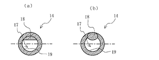
主に不要反射光を遮光する前記絞り14は、投写レンズ9の光軸上の光束断面積及び光軸外の光束断面積の大きさを決定する開口絞りであり、該絞り14の開口は、その重心が光軸に対して偏心するか又はその形状が光軸に対して非対称であるかのいずれか、すなわち絞り14は非対称絞りである。該絞り14の開口の形状の一部は、好ましくは遮蔽部によって定められる。該遮蔽部は、主に不要反射光を遮光するといった絞り14を設けたことによる効果の発現を考慮すると、実質、投写光学系8に入射してしまう不要反射光の照射位置(不要反射光領域)に少なくとも存在していることが好ましい。図2に、本実施形態における絞り14の開口形状と遮蔽部との関係の好適な一例を示す。図2(a)は、円19に半円形の遮蔽部18が設けられた形状の開口17を有する絞り14を示す模式図で、反射型ライトバルブ側の全面(斜線部分)に後述する特定反射防止構造体及び特定材料が存在する。図2(b)は、円19に楕円形の遮蔽部18が設けられた形状の開口17を有する絞り14を示す模式図で、反射型ライトバルブ側の全面(斜線部分)に特定反射防止構造体及び特定材料が存在している。なお図2では、円19に半円形又は楕円形の遮蔽部18が設けられた形状の開口17を有する絞り14を図示したが、他にも例えば、円に円形、三日月形などの遮蔽部が設けられた形状の開口を有する絞りや、多角形に半円形、円形、楕円形、三日月形などの遮蔽部が設けられた形状の開口を有する絞り、多角形に多角形の遮蔽部が設けられた形状の開口を有する絞りなども例示され、非対称絞りである限り絞り14には特に限定がない。本実施形態においては、絞り14にて遮光する投写光が光束であり、絞り14で不要な回折現象などができる限り生じないのが望ましいことを考慮すると、遮蔽部が半円形、円形又は楕円形であることが好ましく、円に半円形、円形又は楕円形の遮蔽部が設けられた形状の開口を有する非対称絞りが好ましい。
The
なお、例えば図9には不要反射光領域51を楕円形状で示したが、かかる不要反射光領域の形状は、照明光学系の構成や投写光学系の構成、また反射型ライトバルブとこれらとの位置関係などによって変化する。したがって、前記図2やその他例示した絞り14の開口の形状はほんの一例であり、不要反射光を充分に遮光し得るように投写型表示装置の構成に応じて開口の形状を適宜変更することが好ましい。
For example, FIG. 9 shows the unnecessary reflected
前記絞り14の反射型ライトバルブ6側の面の少なくとも一部には、特定構造の反射防止構造体及び投写光を吸収可能な材料が存在するので、本実施形態に係る投写型表示装置においては、前記のごとき不要反射光及び僅かな入射光は、絞り14の表面での反射自体が充分に防止され、なおかつ多少反射したとしても絞り14の内部に吸収されてしまい、従来の投写型表示装置とは比較にならないほど、スクリーン上に投写されたり、反射型ライトバルブへ戻って目的とする投写画像に悪影響を及ぼす光を大幅に削減することができるのである。
In at least a part of the surface of the
反射防止構造体とは、所定の形状を有する構造単位が、投写光の波長(通常、約400〜700nm)の下限値よりも小さいピッチ、すなわち投写光の最短波長よりも小さいピッチで周期的にアレイ状に配列されたものである。このように所定の形状を有する構造単位を周期的にアレイ状に配列させることによって、投写光に対して、見かけ上屈折率を連続的に変化させ、空気層との界面での透過/反射特性の入射角依存性及び波長依存性が少ない反射防止機能面を形成させることができる。 The antireflection structure is a structure in which a structural unit having a predetermined shape is periodically formed at a pitch smaller than the lower limit value of the wavelength of projection light (usually about 400 to 700 nm), that is, at a pitch smaller than the shortest wavelength of projection light. They are arranged in an array. By periodically arranging the structural units having a predetermined shape in the form of an array, the apparent refractive index of the projected light is continuously changed, and the transmission / reflection characteristics at the interface with the air layer. It is possible to form an antireflection functional surface with little incidence angle dependency and wavelength dependency.
なお前記ピッチとは、反射防止構造体が多数の微細構造単位の二次元的な配列により構成されている場合には、最も密な配列方向におけるピッチを意味する。 In addition, the said pitch means the pitch in the densest arrangement direction, when the reflection preventing structure is comprised by the two-dimensional arrangement | sequence of many fine structure units.
また反射防止構造体とは、投写光のなかで、絞り14で遮光された、不要反射光及び投写画像に寄与すべき有効な僅かな入射光(以下、反射を低減すべき光という)の反射を防止するために、表面に微細構造が形成された部材を意味し、反射を低減すべき光を完全に反射させない態様だけではなく、所定波長の反射を低減すべき光の反射を防止する効果を有する態様も含むものである。
The antireflection structure is a reflection of unnecessary reflected light and effective small incident light (hereinafter referred to as light whose reflection should be reduced) that is shielded by the
本実施形態に用いることができる反射防止構造体としては、例えば図3Aの概略拡大図に示すような、高さH1の円錐形状の突起を構造単位とし、これら円錐形状の突起がピッチP1で周期的にアレイ状に配列された構造体があげられる。 As the antireflection structure that can be used in the present embodiment, for example, conical protrusions having a height H1 as shown in the schematic enlarged view of FIG. 3A are used as structural units, and these conical protrusions have a pitch P1 and a period. In particular, there are structures arranged in an array.
構造単位のピッチP1は、反射防止構造体中、一配列方向において実質上略一定であり、投写光の最短波長よりも小さければよいが、界面での透過/反射特性の入射角依存性及び波長依存性をより一層低減させることができるという点から、かかるピッチP1は投写光の最短波長の1/2以下、さらには1/3以下であることが好ましい。なお例えば後述するような反射防止構造体の製造性を考慮すると、かかるピッチP1はある程度の大きさを有することが望ましく、通常投写光の最短波長の1/5程度以上であることが好ましい。 The pitch P1 of the structural unit is substantially constant in one arrangement direction in the antireflection structure and may be smaller than the shortest wavelength of the projection light, but the incident angle dependence and wavelength of the transmission / reflection characteristics at the interface From the viewpoint that the dependency can be further reduced, the pitch P1 is preferably 1/2 or less, more preferably 1/3 or less of the shortest wavelength of the projection light. For example, considering the manufacturability of the antireflection structure as described later, it is desirable that the pitch P1 has a certain size, and is preferably about 1/5 or more of the shortest wavelength of normal projection light.
また構造単位の高さH1には特に限定がなく、反射防止構造体中、全ての構造単位の高さH1が必ずしも一定でなくてもよいが、かかる高さH1が高いほど、投写光のなかで、非対称絞りで遮光された反射を低減すべき光に対する反射防止機能が向上するという利点がある。したがって該構造単位の高さH1は、少なくとも前記ピッチP1以上(最小の構造単位の高さがピッチ以上)、さらには少なくともピッチP1の3倍以上(最小の構造単位の高さがピッチの3倍以上)であることが好ましい。なおやはり、例えば後述するような反射防止構造体の製造性を考慮すると、かかる高さH1がある程度の大きさまでであることが望ましく、通常高くともピッチP1の5倍程度以下(最大の構造単位の高さがピッチの5倍程度以下)であることが好ましい。 Further, the height H1 of the structural unit is not particularly limited, and the height H1 of all the structural units in the antireflection structure does not necessarily have to be constant. However, the higher the height H1, the more the projected light. Thus, there is an advantage that the antireflection function for the light that should reduce the light shielded by the asymmetric diaphragm is improved. Accordingly, the height H1 of the structural unit is at least the pitch P1 or more (the minimum structural unit height is at least the pitch), and at least three times the pitch P1 (the minimum structural unit height is three times the pitch). Or more). In view of the manufacturability of the antireflection structure as described later, for example, it is desirable that the height H1 is up to a certain size, and usually not more than about 5 times the pitch P1 (the maximum structural unit). The height is preferably about 5 times or less of the pitch.
本実施形態においては、前記したように、反射防止構造体として構造単位が例えば円錐形状(図3A)の構造体を用いることができるが、必ずしもこのような形状の構造体に限定されるものではなく、例えば構造単位が正六角錐形状や、四角錐形状などの角錐形状(図3B)の構造体であってもよい。また、かかる構造単位の形状は必ずしも錐状に限定されるものでもなく、円柱形状(図4A)や角柱形状(図4B)などの柱状であっても、先端が丸くなっている釣鐘状(図5A及び図5B)であっても、円錐台形状(図6A)や角錐台形状(図6B)などの錐台状であってもよい。また、各構造単位は厳密な幾何学的な形状である必要はなく、実質的に錐状、柱状、釣鐘状、錐台状などであればよい。 In the present embodiment, as described above, a structure having, for example, a conical shape (FIG. 3A) can be used as the antireflection structure, but the structure is not necessarily limited to such a structure. For example, the structural unit may be a pyramid-shaped structure (FIG. 3B) such as a regular hexagonal pyramid shape or a quadrangular pyramid shape. Further, the shape of such a structural unit is not necessarily limited to a conical shape, and even if it is a columnar shape (FIG. 4A) or a prismatic shape (FIG. 4B), a bell shape (FIG. 5A and FIG. 5B) may be a truncated cone shape such as a truncated cone shape (FIG. 6A) or a truncated pyramid shape (FIG. 6B). Moreover, each structural unit does not need to be a strict geometric shape, and may be substantially a cone shape, a column shape, a bell shape, a frustum shape, or the like.
さらに前記図3〜6では、反射防止構造体として構造単位が突出形状のものを示しているが、本実施形態においてはこのような突出形状のものに限定されることもなく、例えば平面に錐状、柱状、釣鐘状、錐台状などの陥没形状の構造単位が、投写光の最短波長よりも小さいピッチで周期的にアレイ状に配列するように形成された反射防止構造体を用いることも可能である。また突出形状の構造単位と陥没形状の構造単位とが1つの反射防止構造体中に同時に存在していてもよい。なお、かかる突出形状の構造単位と陥没形状の構造単位とが同時に存在した反射防止構造体の場合、その突出部の高さと陥没部の深さとの合計が前記高さH1の範囲内であることが好ましい。このように、本実施形態に用いられる反射防止構造体は、各構造単位が投写光の最短波長よりも小さいピッチで周期的にアレイ状に配列され、反射を低減すべき光の反射を充分に防止することができるものであれば、その構造単位の形状などは特に限定されるものではない。 Further, in FIGS. 3 to 6, the structural unit has a protruding shape as the antireflection structure. However, the present embodiment is not limited to such a protruding shape. An anti-reflection structure formed such that the structural units in the shape of depressions, such as shapes, columns, bells, and frustums, are periodically arranged in an array at a pitch smaller than the shortest wavelength of the projection light. Is possible. Further, the projecting-shaped structural unit and the depressed-shaped structural unit may be simultaneously present in one antireflection structural body. In addition, in the case of an antireflection structure in which such a projecting shape structural unit and a depressed shape structural unit exist at the same time, the sum of the height of the projected portion and the depth of the depressed portion is within the range of the height H1. Is preferred. As described above, in the antireflection structure used in the present embodiment, each structural unit is periodically arranged in an array at a pitch smaller than the shortest wavelength of the projection light, so that sufficient reflection of light that should be reduced in reflection is achieved. As long as it can be prevented, the shape of the structural unit is not particularly limited.
なお本実施形態においては、空気界面で投写光の屈折率が連続的に変化し、反射を低減すべき光の反射をより充分に防止することができるという点から、構造単位が略錐状の突出形状及び/又は略錐状の陥没形状である反射防止構造体を用いることが好ましく、略錐状が略正六角錐状である場合には、構造単位が高充填率で配列され、空気界面で投写光の屈折率がさらに連続的に変化するといった透過特性がより一層向上するという点から、特に好ましい。 In the present embodiment, the refractive index of the projection light continuously changes at the air interface, and the structural unit has a substantially conical shape from the viewpoint that reflection of light whose reflection should be reduced can be more sufficiently prevented. It is preferable to use an antireflection structure having a protruding shape and / or a substantially conical depression shape. When the substantially conical shape is a substantially regular hexagonal pyramid shape, the structural units are arranged at a high filling rate, and the air interface is This is particularly preferable from the viewpoint of further improving the transmission characteristics such that the refractive index of the projection light further changes continuously.
絞り14の少なくとも一部を前記反射防止構造体と共に構成する、投写光を吸収可能な材料としては、通常約400〜700nmの波長の光を吸収することができる材料であれば特に限定がなく、例えば黒色材料を好適に用いることができる。かかる黒色材料は、例えばポリカーボネート系樹脂、アクリル系樹脂などの樹脂に、シアン、マゼンタ、イエローなどの色素を混合して得られる黒色染料(例えば、Plast Black 8950、Plast Black 8970(いずれも商品名、有本化学工業(株)製))などの染料や、カーボンブラックなどの顔料を含有させることによって得ることができる。
The material that can absorb the projection light and that constitutes at least a part of the
本実施形態において絞り14は、その反射型ライトバルブ6側の面の少なくとも一部に反射防止構造体と投写光を吸収可能な材料とを有するものであるが、絞り14を設けることによる反射を低減すべき光に対する反射防止及び吸収効果の発現を考慮すると、例えば図2に示すように、絞り14全体が反射防止構造体及び投写光を吸収可能な材料で構成されていることが最も好ましく、少なくとも遮蔽部18によって一部形成される開口17の非対称部分かつ開口17の周囲といった、反射を低減すべき光が照射される可能性が高い部分に、反射防止構造体と投写光を吸収可能な材料とが存在することが好ましい。
In this embodiment, the
絞り14において、反射防止構造体と照明光を吸収可能な材料との関係は、反射を低減すべき光に対する反射防止及び吸収効果が充分に発現される限り特に限定がない。例えば基材上に反射防止構造体が該基材と一体化して形成されており、これら反射防止構造体及び基材全体がいずれも投写光を吸収可能な材料からなるものであってもよく、またいずれも投写光を吸収可能な材料からなる反射防止構造体及び基材が、別々に形成された後に一体化されていてもよい。さらに、例えば透明樹脂などの任意の材料からなる基材上に投写光を吸収可能な材料からなる反射防止構造体が形成されていてもよく、投写光を吸収可能な材料からなる基材上に例えば透明樹脂などの任意の材料からなる反射防止構造体が形成されていてもよい。なお反射を低減すべき光に対する反射防止及び吸収効果のさらなる充分な発現を考慮すると、反射防止構造体及び基材全体が投写光を吸収可能な材料からなるものであることが好ましい。
In the
反射防止構造体と投写光を吸収可能な材料とを有する絞りの製造方法にも特に限定がないが、一例として、例えば石英ガラス基板などに電子線描画などの方法でパターンを描画してドライエッチングなどの加工を行い、予め反射防止構造体と同一形状に精密加工された高精度のマスター型を形成した後、該マスター型を用いて、加熱軟化したガラス材料をプレス成形することによってガラス製の反射防止構造体成形用型を作製し、該反射防止構造体成形用型を用いて、例えば前記黒色材料(黒色樹脂)などの投写光を吸収可能な材料をプレス成形に供する方法などがあげられる。かかる方法を採用した場合には、反射防止構造体と投写光を吸収可能な材料とを有する絞り14を安価でかつ大量に製造することができる。
There is no particular limitation on the manufacturing method of the diaphragm having the antireflection structure and the material that can absorb the projection light, but as an example, for example, dry etching is performed by drawing a pattern on a quartz glass substrate or the like by a method such as electron beam drawing. After forming a high-precision master mold that has been precisely machined into the same shape as the antireflection structure in advance, the master mold is used to press-mold the heat-softened glass material. For example, a method for producing an antireflection structure molding die, and using the antireflection structure molding die, a material capable of absorbing projection light, such as the black material (black resin), is subjected to press molding. . When such a method is adopted, the
また前記の他にも、本実施形態に用いる絞り14を製造する際には、例えばアルミニウム、真鍮、アルミニウム−マグネシウム合金などの金属類を用い、成形、エッチング、X線リソグラフィ、フォトリソグラフィなどを適宜組み合わせる方法を採用することも可能である。なお、ロッドプリズム3から出射され、反射型ライトバルブ6で反射する光の強度は通常高いため、反射を低減すべき光もある程度の強度を有する。したがって、絞り14は比較的高温となる可能性があるので、かかる絞り14としては、前記金属類などの耐熱性を有する材料からなるものをより好適に用いることができる。
In addition to the above, when manufacturing the
なお絞り14を製造する際には、いわゆる絞り板と遮蔽部18とを一体的に製造して所望形状の開口17を有する絞り14としてもよいし、絞り板と遮蔽部18とを別々に製造して所望形状の開口17となるように一体化してもよく、特に限定はない。
When the
このように、本実施形態における絞りは、所定の突出形状や陥没形状を有する構造単位が投写光の最短波長よりも小さいピッチで周期的にアレイ状に配列された反射防止構造体と、黒色材料などの投写光を吸収可能な材料とを、反射型ライトバルブ6側の面の少なくとも一部に有するものであるので、本実施形態の投写型表示装置では、非対称絞りで遮光した反射を低減すべき光の反射率を著しく低下させ、かつ実質的に略完全に吸収することが可能であり、コントラストの低下やゴーストの形成を極力抑制し、高品質の投写画像を形成することができる。 As described above, the diaphragm according to the present embodiment includes an antireflection structure in which structural units having a predetermined protruding shape and a depressed shape are periodically arranged in an array at a pitch smaller than the shortest wavelength of the projection light, and a black material. The projection light display device according to the present embodiment reduces the reflection blocked by the asymmetric diaphragm. It is possible to remarkably reduce the reflectivity of power and to absorb substantially completely, and to suppress a reduction in contrast and the formation of ghosts as much as possible and form a high-quality projected image.
本実施形態の投写型表示装置は前記のごとき構成のものであるが、例えば本投写型表示装置をカラー画像投写に用いる場合には、前記照明光学系10内のロッドプリズム3と光学ユニットである全反射プリズム5Aとの間にカラーホイールを配置すればよい。カラーホイールは、図7の概略図に示すように、ロッドプリズム3からの光を、場所により赤色(R)又は緑色(G)又は青色(B)の光のみ透過させるような光学多層膜を施した円盤であり、これを1秒間に通常120回程度回転させてRGBのサイクルを繰り返し、反射型ライトバルブ6上へのRGB3原色の時分割照射を可能にするものである。なおここで反射型ライトバルブ6としてDMDが用いられている場合、該DMDでは各色の映像信号に対応させて制御がなされる。
The projection display device of the present embodiment has the above-described configuration. For example, when the projection display device is used for color image projection, the projection display device is the
なお前記カラーホイール上のRGBの配置は、図7に示す配置に限定されるものではなく、本発明の目的を阻害しない限り、例えばさらにRGBの分割数を多くしたものであってもよく、輝度を向上させるために一部透明な領域が施されたものであってもよい。またこれらの他にも、反射型のカラーホイールを用いることも可能である。 Note that the arrangement of RGB on the color wheel is not limited to the arrangement shown in FIG. 7, and may be, for example, a further increased number of RGB divisions as long as the object of the present invention is not impaired. In order to improve this, a partly transparent region may be provided. In addition to these, it is also possible to use a reflective color wheel.
本実施形態に係る投写型表示装置は、以上説明したように、照明光学系、光学ユニット、反射型ライトバルブ及び投写光学系を備え、必要に応じてカラーホイールが配置されたものであり、該投写光学系内の非対称絞りの、反射型ライトバルブ側の面の少なくとも一部に特定の反射防止構造体及び材料が存在する限り、その構造に特に限定はない。したがって、該投写型表示装置は、例えば前記図1に示したようなフロントタイプの投写型表示装置であってもよく、またリアタイプの投写型表示装置であってもよい。 As described above, the projection display device according to the present embodiment includes an illumination optical system, an optical unit, a reflective light valve, and a projection optical system, and a color wheel is disposed as necessary. As long as the specific antireflection structure and material are present on at least a part of the surface of the asymmetric diaphragm in the projection optical system on the reflective light valve side, the structure is not particularly limited. Therefore, the projection display device may be a front type projection display device as shown in FIG. 1, for example, or may be a rear type projection display device.
(第2の実施形態)
本発明の第2の実施形態として、前記第1の実施形態に係る投写型表示装置を一部変更した、3つの反射型ライトバルブ及び3色分解プリズムを備えた投写型表示装置があげられる。すなわち、第2の実施形態に係る投写型表示装置は、第1の実施形態と同様の照明光学系と、光学ユニットと、非対称絞りを備えた投写光学系とが配置され、これに3つの反射型ライトバルブと、光学ユニットとしてさらに3色分解プリズムとが備えられたものである。かかる3色分解プリズムで3色に分解された赤色(R)、緑色(G)、青色(B)の光は、各々対応する3つの反射型ライトバルブに与えられ、ここで形成される各色の光学像が、3色分解プリズムで合成されて投写光学系によりスクリーン上に投写される。
(Second Embodiment)
As a second embodiment of the present invention, there is a projection display device that includes three reflective light valves and a three-color separation prism, in which the projection display device according to the first embodiment is partially changed. That is, the projection display apparatus according to the second embodiment includes an illumination optical system, an optical unit, and a projection optical system that includes an asymmetric stop, which are the same as those of the first embodiment, and three reflections on this. A type light valve and a three-color separation prism as an optical unit are further provided. The red (R), green (G), and blue (B) light separated into the three colors by the three-color separation prism is supplied to the corresponding three reflection type light valves, and each color formed here The optical image is synthesized by the three-color separation prism and projected on the screen by the projection optical system.
3色分解プリズムは、3つのプリズムが接合されたものであり、例えば第1のプリズムと第2のプリズムとの界面ではBの光のみが反射され、第2のプリズムと第3のプリズムとの界面ではRの光のみが反射される。これにより、光学ユニットである全反射プリズムからの照明光(白色光)は、R、G、Bの3色の光に分解され、第1〜第3の各プリズムの後方に配置された各々対応する第1〜第3の反射型ライトバルブに入射する。 The three-color separation prism is formed by joining three prisms. For example, only the B light is reflected at the interface between the first prism and the second prism, and the second prism and the third prism are connected. Only R light is reflected at the interface. Thereby, the illumination light (white light) from the total reflection prism which is an optical unit is decomposed into light of three colors of R, G, and B, and each is arranged behind each of the first to third prisms. The light enters the first to third reflective light valves.
ここで本実施形態の場合、前記第1の実施形態のような、反射型ライトバルブを照明した照明光の一部が例えばDMDの微少ミラーに到達する前にカバーガラスと空気との界面で反射して生じる不要反射光に加え、さらに前記3色分解プリズムの界面で発生する不要反射光も投写画像のコントラスト性能に影響を及ぼすことになる。 In this embodiment, as in the first embodiment, a part of the illumination light illuminating the reflective light valve is reflected at the interface between the cover glass and the air before reaching the micro mirror of the DMD, for example. In addition to unnecessary reflected light generated in this manner, unnecessary reflected light generated at the interface of the three-color separation prism also affects the contrast performance of the projected image.
そこで本実施形態においても、コントラストの低下及びゴーストの形成に関する問題を解決すべく、投写光学系内の絞りで投写光の一部(実質、主に第1〜第3各反射型ライトバルブの有効表示領域を覆うカバーガラスと空気との界面で反射した不要反射光及び3色分解プリズムの界面で発生した不要反射光)を遮光している。該絞りは、投写レンズの光軸上の光束断面積及び光軸外の光束断面積の大きさを決定する開口絞りであり、絞りの開口は、その重心が光軸に対して偏心するか又はその形状が光軸に対して非対称であるかのいずれか、すなわち本実施形態における絞りも非対称絞りである。しかも該絞りは単なる非対称絞りではなく、その反射型ライトバルブ側の面の少なくとも一部に、前記第1の実施形態と同様に、特定構造体及び特定材料が存在するものであるので、該絞りの表面では、主に不要反射光と、絞りの表面で僅かに遮光された投写画像に寄与すべき有効な光(入射光)との反射が極力抑制され、かつこれらの光が内部に吸収される。 Therefore, in this embodiment as well, in order to solve the problems related to the decrease in contrast and the formation of ghosts, a part of the projection light (substantially, mainly the first to third reflection type light valves are effective in the projection optical system). Unnecessary reflected light reflected at the interface between the cover glass and the air covering the display area and unnecessary reflected light generated at the interface of the three-color separation prism) are shielded. The stop is an aperture stop that determines the size of the light beam cross-sectional area on the optical axis of the projection lens and the size of the light beam cross-sectional area outside the optical axis, and the aperture of the stop has its center of gravity decentered with respect to the optical axis or Either the shape of the diaphragm is asymmetric with respect to the optical axis, that is, the diaphragm in this embodiment is also an asymmetric diaphragm. In addition, the diaphragm is not a mere asymmetric diaphragm, and a specific structure and a specific material are present on at least a part of the reflective light valve side surface as in the first embodiment. On the surface, the reflection of unwanted reflected light and effective light (incident light) that should contribute to the projected image that is slightly shielded from the surface of the stop is suppressed as much as possible, and these lights are absorbed inside. The
前記絞りの開口の形状の一部は、好ましくは遮蔽部によって定められる。該遮蔽部は、主に不要反射光を遮光するといった絞りを設けたことによる効果の発現を考慮すると、実質、投写光学系に入射してしまう不要反射光の照射位置(不要反射光領域)に少なくとも存在していることが好ましい。なお遮蔽部及び該遮蔽部によってその開口の形状の一部が定められる絞りとしては、例えば前記第1の実施形態において例示したものが好適に適用される。また不要反射光領域の形状は、照明光学系の構成や投写光学系の構成、また反射型ライトバルブとこれらとの位置関係などによって変化する。したがって、前記図2やその他例示した絞りの開口の形状はほんの一例であり、不要反射光を充分に遮光し得るように投写型表示装置の構成に応じて開口の形状を適宜変更することが好ましい。 A part of the shape of the aperture of the diaphragm is preferably defined by a shielding part. In consideration of the manifestation of the effect of providing a diaphragm that mainly shields unnecessary reflected light, the shielding portion is substantially at the irradiation position (unnecessary reflected light region) of unnecessary reflected light that enters the projection optical system. It is preferably present at least. In addition, as a diaphragm in which a part of the shape of the opening is defined by the shielding part and the shielding part, for example, those exemplified in the first embodiment are suitably applied. The shape of the unnecessary reflected light region changes depending on the configuration of the illumination optical system, the configuration of the projection optical system, the positional relationship between the reflective light valve and these, and the like. Therefore, the shape of the aperture of the diaphragm illustrated in FIG. 2 and other examples is only an example, and it is preferable to appropriately change the shape of the aperture according to the configuration of the projection display device so that unnecessary reflected light can be sufficiently shielded. .
絞りは、第1の実施形態と同様の、所定の突出形状や陥没形状を有する構造単位が投写光の最短波長よりも小さいピッチで周期的にアレイ状に配列された反射防止構造体と、黒色材料などの投写光を吸収可能な材料とを、その反射型ライトバルブ側の面の少なくとも一部に設けることによって構成されているので、このような非対称絞りにより、本実施形態の投写型表示装置でも、前記第1の実施形態に係る投写型表示装置のように、2種の不要反射光及び投写画像に寄与すべき僅かな入射光、すなわち反射を低減すべき全ての光の反射率を著しく低下させ、かつ実質的に略完全に吸収することが可能である。したがって、本実施形態の投写型表示装置により、コントラストの低下やゴーストの形成が極力抑制された、高品質の投写画像を形成することができる。 As in the first embodiment, the stop includes an antireflection structure in which structural units having a predetermined protruding shape or depression shape are periodically arranged in an array at a pitch smaller than the shortest wavelength of the projection light, and a black color. The projection display device of the present embodiment is configured by such an asymmetric diaphragm because a material capable of absorbing projection light such as a material is provided on at least a part of the surface of the reflective light valve side. However, like the projection display device according to the first embodiment, the reflectance of the two types of unnecessary reflected light and the slight incident light that should contribute to the projected image, that is, all the light that should be reduced in reflection, is remarkably increased. It is possible to reduce and to absorb substantially completely. Therefore, the projection display device according to the present embodiment can form a high-quality projected image in which the reduction in contrast and the formation of ghosts are suppressed as much as possible.
本実施形態に係る投写型表示装置は、以上説明したように、照明光学系、3色分解プリズムを含む光学ユニット、3つの反射型ライトバルブ及び投写光学系を備えたカラー画像投写用の投写型表示装置で、該投写光学系内の非対称絞りの、反射型ライトバルブ側の面の少なくとも一部に特定の反射防止構造体及び材料が存在する限り、その構造に特に限定はない。したがって、該投写型表示装置は、フロントタイプの投写型表示装置であってもよく、またリアタイプの投写型表示装置であってもよい。 As described above, the projection display device according to the present embodiment is a projection type for color image projection including an illumination optical system, an optical unit including a three-color separation prism, three reflective light valves, and a projection optical system. In the display device, the structure is not particularly limited as long as a specific antireflection structure and material are present on at least a part of the reflective light valve side surface of the asymmetric diaphragm in the projection optical system. Therefore, the projection display device may be a front type projection display device or a rear type projection display device.
(第3の実施形態)
本発明の第3の実施形態に係る投写光学系は、投写型表示装置に用いられ、ライトバルブで形成された光学像である投写光を投写するものであり、該投写光の一部を遮光する絞りの開口が、その重心が投写レンズの光軸に対して偏心しているか又は投写レンズの光軸に対して非対称な形状のものである。そして、本投写光学系における大きな特徴の1つは、前記絞りが、そのライトバルブ側の面の少なくとも一部に、
所定の形状を有する構造単位が投写光の最短波長よりも小さいピッチで周期的にアレイ状に配列された反射防止構造体、及び
投写光を吸収可能な材料
を有することである。
(Third embodiment)
A projection optical system according to the third embodiment of the present invention is used in a projection display device, and projects projection light that is an optical image formed by a light valve, and blocks part of the projection light. The aperture of the stop is shaped such that its center of gravity is decentered with respect to the optical axis of the projection lens or asymmetric with respect to the optical axis of the projection lens. One of the major features of this projection optical system is that the stop is at least partially on the light valve side surface.
The structural unit having a predetermined shape has an antireflection structure in which the structural units are periodically arranged in an array at a pitch smaller than the shortest wavelength of the projection light, and a material capable of absorbing the projection light.
本実施形態の投写光学系の好適な一例として、例えば図1に示すような、前記第1の実施形態に係る投写型表示装置における投写光学系8などがあげられる。該投写光学系8は、ライトバルブの一例である反射型ライトバルブ6で形成された光学像(投写光)を投写するものである。本実施形態の投写光学系は、例えば図1に示すように、少なくとも投写レンズ9及び絞り14を備えたものである。なお本実施形態においても、投写光とは、ライトバルブを照明した光のうち、該ライトバルブで形成された、投写光学系内に入射する光(光学像)のことを意味する。
As a suitable example of the projection optical system of the present embodiment, for example, a projection optical system 8 in the projection display apparatus according to the first embodiment as shown in FIG. The projection optical system 8 projects an optical image (projection light) formed by a reflective light valve 6 which is an example of a light valve. The projection optical system of the present embodiment includes at least a projection lens 9 and an
本実施形態の投写光学系の特徴は、投写光の一部を遮光する絞りの開口が、その重心が投写レンズの光軸に対して偏心しているか又は投写レンズの光軸に対して非対称な形状のもの、すなわち絞りが非対称絞りであり、該絞りが、そのライトバルブ側の面の少なくとも一部に、特定構造の反射防止構造体及び投写光を吸収可能な材料を有することである。 The projection optical system according to the present embodiment is characterized in that the aperture of the diaphragm that blocks part of the projection light has a shape whose center of gravity is decentered with respect to the optical axis of the projection lens or asymmetric with respect to the optical axis of the projection lens. In other words, the diaphragm is an asymmetric diaphragm, and the diaphragm has an antireflection structure having a specific structure and a material capable of absorbing projection light on at least a part of the surface on the light valve side.
前記絞り14は、第1の実施形態にて説明したように、投写光学系8内に入射した投写光の一部(実質、主に反射型ライトバルブ6の有効表示領域を覆うカバーガラス7と空気との界面で反射した不要反射光)を遮光する特定形状の絞り(非対称絞り)である。しかも該絞り14は単なる非対称絞りではなく、その反射型ライトバルブ6側の面の少なくとも一部に、特定構造体及び特定材料が存在するものであるので、該絞り14の表面では、主に不要反射光と、絞り14の表面で僅かに遮光された投写画像に寄与すべき有効な光(入射光)との反射が極力抑制され、かつこれらの光が内部に吸収される。
As described in the first embodiment, the
なお本実施形態の投写光学系を用い、実際に投写型表示装置とする場合、反射型ライトバルブなどのライトバルブと投写光学系との配置、投写レンズの種類などに応じて適宜変化するが、前記絞りと投写レンズの入射瞳とは通常30mm程度以下の間隔に位置するので、絞りが入射瞳の近傍に位置する場合、特に絞りが入射瞳と光軸上同一位置となる場合もある。 Note that when the projection optical system of the present embodiment is used and the projection display apparatus is actually used, it varies depending on the arrangement of the light valve such as the reflective light valve and the projection optical system, the type of the projection lens, etc. Since the stop and the entrance pupil of the projection lens are usually located at an interval of about 30 mm or less, when the stop is located in the vicinity of the entrance pupil, in particular, the stop may be at the same position on the optical axis as the entrance pupil.
主に不要反射光を遮光する前記絞りは、投写レンズの光軸上の光束断面積及び光軸外の光束断面積の大きさを決定する開口絞りであり、該絞りの開口は、その重心が光軸に対して偏心するか又はその形状が光軸に対して非対称であるかのいずれか、すなわち該絞りは非対称絞りである。該絞りの開口の形状の一部は、前記第1の実施形態の場合と同様に、好ましくは遮蔽部によって定められる。該遮蔽部は、主に不要反射光を遮光するといった絞りを設けたことによる効果の発現を考慮すると、実質、投写光学系に入射してしまう不要反射光の照射位置(不要反射光領域)に少なくとも存在していることが好ましい。 The diaphragm that mainly shields unnecessary reflected light is an aperture diaphragm that determines the size of the beam cross-sectional area on the optical axis of the projection lens and the cross-sectional area of the light beam outside the optical axis. Either it is decentered with respect to the optical axis or its shape is asymmetric with respect to the optical axis, i.e. the stop is an asymmetric stop. A part of the shape of the aperture of the diaphragm is preferably defined by a shielding part, as in the case of the first embodiment. In consideration of the manifestation of the effect of providing a diaphragm that mainly shields unnecessary reflected light, the shielding portion is substantially at the irradiation position (unnecessary reflected light region) of unnecessary reflected light that enters the projection optical system. It is preferably present at least.
本実施形態における絞りとしては、前記第1の実施形態にて説明したように、例えば図2に示すものなどが好ましく例示され、他にも例えば、円に円形、三日月形などの遮蔽部が設けられた形状の開口を有する絞りや、多角形に半円形、円形、楕円形、三日月形などの遮蔽部が設けられた形状の開口を有する絞り、多角形に多角形の遮蔽部が設けられた形状の開口を有する絞りなども例示されるが、非対称絞りである限り絞りには特に限定がない。本実施形態においても、絞りにて遮光する投写光が光束であり、絞りで不要な回折現象などができる限り生じないのが望ましいことを考慮すると、遮蔽部が半円形、円形又は楕円形であることが好ましく、円に半円形、円形又は楕円形の遮蔽部が設けられた形状の開口を有する非対称絞りが好ましい。 As described in the first embodiment, for example, the diaphragm shown in FIG. 2 is preferably exemplified as the diaphragm in the first embodiment. In addition, for example, a circular or crescent shaped shielding portion is provided on the circle. A diaphragm having an aperture of a predetermined shape, a diaphragm having an aperture of a shape provided with a shielding part such as a semicircular, circular, elliptical, or crescent shape in a polygon, and a polygonal shielding part in a polygon A diaphragm having an aperture having a shape is also exemplified, but the diaphragm is not particularly limited as long as it is an asymmetric diaphragm. Also in this embodiment, considering that it is desirable that the projection light shielded by the diaphragm is a light beam and unnecessary diffraction phenomenon or the like is not generated as much as possible by the diaphragm, the shielding portion is semicircular, circular or elliptical. Preferably, an asymmetric diaphragm having an opening having a shape in which a semicircular, circular, or elliptical shielding portion is provided in a circle is preferable.
なお、例えば図9には不要反射光領域51を楕円形状で示したが、かかる不要反射光領域の形状は、実際に投写型表示装置とする場合に、本投写光学系の構成や、適宜用いる照明光学系の構成、また反射型ライトバルブなどのライトバルブとこれらとの位置関係などによって変化する。したがって、前記図2やその他例示した絞りの開口の形状はほんの一例であり、不要反射光を充分に遮光し得るように、実際の投写型表示装置の構成に応じて開口の形状を適宜変更することが好ましい。
For example, in FIG. 9, the unnecessary reflected
前記絞りのライトバルブ側の面の少なくとも一部には、特定構造の反射防止構造体及び投写光を吸収可能な材料が存在するので、本実施形態に係る投写光学系においては、前記のごとき不要反射光及び僅かな入射光は、絞りの表面での反射自体が充分に防止され、なおかつ多少反射したとしても絞りの内部に吸収されてしまい、本投写光学系を備えた投写型表示装置は、従来の投写光学系を備えた投写型表示装置とは比較にならないほど、スクリーン上に投写されたり、ライトバルブへ戻って目的とする投写画像に悪影響を及ぼす光を大幅に削減することができるのである。 Since at least part of the light valve side surface of the stop has an antireflection structure with a specific structure and a material that can absorb projection light, the projection optical system according to the present embodiment does not require the above Reflected light and a small amount of incident light are sufficiently prevented from being reflected on the surface of the diaphragm itself, and even if reflected slightly, they are absorbed inside the diaphragm, and the projection display apparatus equipped with this projection optical system As compared with a conventional projection display device equipped with a projection optical system, light projected on the screen or returned to the light valve and adversely affecting the target projected image can be greatly reduced. is there.
なお本実施形態に係る投写光学系において、投写レンズや、絞りが有する特定構造の反射防止構造体及び投写光を吸収可能な材料の種類やこれらの存在箇所などとしては、例えば前記第1の実施形態にて詳細に説明したものを各々好適に適用することができる。したがって本実施形態に係る投写光学系は、第1の実施形態に係る投写型表示装置を構成し得るのは勿論のこと、その他の投写型表示装置を構成するものであってもよく、種々の照明光学系、光学ユニット、反射型ライトバルブなどのライトバルブなどと適宜組み合わせて用いることができる。 In the projection optical system according to the present embodiment, the types of the projection lens, the antireflection structure having a specific structure of the stop, the material that can absorb the projection light, the location of these, and the like are, for example, the first embodiment. Each of those described in detail in the form can be preferably applied. Therefore, the projection optical system according to the present embodiment can constitute the projection display apparatus according to the first embodiment, and may constitute other projection display apparatuses. It can be used in appropriate combination with an illumination optical system, an optical unit, a light valve such as a reflective light valve, and the like.
本発明の投写型表示装置は、各種ビジョンシステムなどに好適に使用することができる。また本発明の投写光学系は、例えば本発明の投写型表示装置などといった各種投写型表示装置に好適に使用することができる。 The projection display device of the present invention can be suitably used for various vision systems. The projection optical system of the present invention can be suitably used for various projection display devices such as the projection display device of the present invention.
1、21 ランプ
2、22 凹面鏡
3、23 ロッドプリズム
4、24 コンデンサーレンズ
5A、5B、25A、25B 全反射プリズム
5a、5b、25a、25b 面
6、26 反射型ライトバルブ
7、27 カバーガラス
8、28 投写光学系
9、29 投写レンズ
10、30 照明光学系
11、31 照明光
12、32 入射光
13、33 非入射光
14、34 絞り
15、35 光入射口
16、36 光出射口
17、37a、37b 開口
18 遮蔽部
1, 21
Claims (8)
前記投写光学系内の、投写光の一部を遮光する絞りの開口が、その重心が投写レンズの光軸に対して偏心しているか又は投写レンズの光軸に対して非対称な形状であり、
前記絞りが、その反射型ライトバルブ側の面の少なくとも一部に、所定の形状を有する構造単位が投写光の最短波長よりも小さいピッチで周期的にアレイ状に配列された反射防止構造体と、投写光を吸収可能な材料とを有することを特徴とする投写型表示装置。 An illumination optical system that collects the emitted light from the light source to illuminate the reflective light valve, an optical unit that guides the illumination light from the illumination optical system to the reflective light valve, and optically reflects the guided illumination light A projection display device comprising: a reflection type light valve that forms an image; and a projection optical system that projects projection light that is an optical image formed by the reflection type light valve;
The aperture of the diaphragm in the projection optical system that blocks part of the projection light has a center of gravity that is decentered with respect to the optical axis of the projection lens or is asymmetric with respect to the optical axis of the projection lens,
An antireflection structure in which the diaphragm has a structural unit having a predetermined shape periodically arranged in an array at a pitch smaller than the shortest wavelength of projection light on at least a part of a surface of the reflective light valve side; And a projection-type display device comprising a material capable of absorbing projection light.
前記投写光の一部を遮光する絞りの開口が、その重心が投写レンズの光軸に対して偏心しているか又は投写レンズの光軸に対して非対称な形状であり、
前記絞りが、そのライトバルブ側の面の少なくとも一部に、所定の形状を有する構造単位が投写光の最短波長よりも小さいピッチで周期的にアレイ状に配列された反射防止構造体と、投写光を吸収可能な材料とを有することを特徴とする投写光学系。
A projection optical system that projects projection light that is an optical image formed by a light valve,
The aperture of the diaphragm that blocks part of the projection light has a center of gravity that is decentered with respect to the optical axis of the projection lens or is asymmetric with respect to the optical axis of the projection lens,
An antireflection structure in which the diaphragm has a structural unit having a predetermined shape periodically arranged in an array at a pitch smaller than the shortest wavelength of the projection light on at least a part of the light valve side surface; and projection A projection optical system comprising: a material capable of absorbing light.
Priority Applications (1)
| Application Number | Priority Date | Filing Date | Title |
|---|---|---|---|
| JP2005133381A JP2006308992A (en) | 2005-04-28 | 2005-04-28 | Projection display device and projection optical system |
Applications Claiming Priority (1)
| Application Number | Priority Date | Filing Date | Title |
|---|---|---|---|
| JP2005133381A JP2006308992A (en) | 2005-04-28 | 2005-04-28 | Projection display device and projection optical system |
Publications (1)
| Publication Number | Publication Date |
|---|---|
| JP2006308992A true JP2006308992A (en) | 2006-11-09 |
Family
ID=37475933
Family Applications (1)
| Application Number | Title | Priority Date | Filing Date |
|---|---|---|---|
| JP2005133381A Pending JP2006308992A (en) | 2005-04-28 | 2005-04-28 | Projection display device and projection optical system |
Country Status (1)
| Country | Link |
|---|---|
| JP (1) | JP2006308992A (en) |
Cited By (7)
| Publication number | Priority date | Publication date | Assignee | Title |
|---|---|---|---|---|
| JP2008197217A (en) * | 2007-02-09 | 2008-08-28 | Mitsubishi Rayon Co Ltd | Molding and method of producing the same |
| JP2009244848A (en) * | 2008-03-10 | 2009-10-22 | Seiko Epson Corp | Light control device, lighting device, and projector |
| JP2011027867A (en) * | 2009-07-23 | 2011-02-10 | Konica Minolta Opto Inc | Optical component, method of manufacturing the optical component, lens assembly and method of manufacturing the lens assembly |
| JP2012137679A (en) * | 2010-12-27 | 2012-07-19 | Sanyo Electric Co Ltd | Projection type display device |
| WO2017094690A1 (en) * | 2015-12-04 | 2017-06-08 | コニカミノルタ株式会社 | Projection-type display device and design method therefor |
| WO2017141753A1 (en) * | 2016-02-15 | 2017-08-24 | コニカミノルタ株式会社 | Projection-type display device |
| CN109416500A (en) * | 2016-06-29 | 2019-03-01 | 麦克赛尔株式会社 | Projection type video display apparatus |
Citations (10)
| Publication number | Priority date | Publication date | Assignee | Title |
|---|---|---|---|---|
| JPH05323263A (en) * | 1992-05-25 | 1993-12-07 | Seiko Epson Corp | Projection type display device |
| JP2001013581A (en) * | 1999-06-25 | 2001-01-19 | Toshiba Corp | Liquid crystal projector |
| JP2002131688A (en) * | 2000-10-26 | 2002-05-09 | Nec Viewtechnology Ltd | Aperture and projector device using the same |
| JP2002182003A (en) * | 2000-12-14 | 2002-06-26 | Canon Inc | Antireflection functional element, optical element, optical system and optical appliance |
| JP2003021868A (en) * | 2001-07-10 | 2003-01-24 | Nikon Corp | Projection type display device |
| JP2003156711A (en) * | 2001-11-20 | 2003-05-30 | Matsushita Electric Ind Co Ltd | Projection type display device |
| JP2003322822A (en) * | 2002-04-30 | 2003-11-14 | Mitsubishi Electric Corp | Picture display device |
| JP2004191878A (en) * | 2002-12-13 | 2004-07-08 | Matsushita Electric Ind Co Ltd | Prism system, projection display device using the same, rear projector, and multi-vision system |
| JP2004258063A (en) * | 2003-02-24 | 2004-09-16 | Seiko Epson Corp | Optical system capable of adjusting quantity of light |
| JP2005025112A (en) * | 2003-07-03 | 2005-01-27 | Nec Viewtechnology Ltd | Color wheel unit and projection type display device therewith |
-
2005
- 2005-04-28 JP JP2005133381A patent/JP2006308992A/en active Pending
Patent Citations (10)
| Publication number | Priority date | Publication date | Assignee | Title |
|---|---|---|---|---|
| JPH05323263A (en) * | 1992-05-25 | 1993-12-07 | Seiko Epson Corp | Projection type display device |
| JP2001013581A (en) * | 1999-06-25 | 2001-01-19 | Toshiba Corp | Liquid crystal projector |
| JP2002131688A (en) * | 2000-10-26 | 2002-05-09 | Nec Viewtechnology Ltd | Aperture and projector device using the same |
| JP2002182003A (en) * | 2000-12-14 | 2002-06-26 | Canon Inc | Antireflection functional element, optical element, optical system and optical appliance |
| JP2003021868A (en) * | 2001-07-10 | 2003-01-24 | Nikon Corp | Projection type display device |
| JP2003156711A (en) * | 2001-11-20 | 2003-05-30 | Matsushita Electric Ind Co Ltd | Projection type display device |
| JP2003322822A (en) * | 2002-04-30 | 2003-11-14 | Mitsubishi Electric Corp | Picture display device |
| JP2004191878A (en) * | 2002-12-13 | 2004-07-08 | Matsushita Electric Ind Co Ltd | Prism system, projection display device using the same, rear projector, and multi-vision system |
| JP2004258063A (en) * | 2003-02-24 | 2004-09-16 | Seiko Epson Corp | Optical system capable of adjusting quantity of light |
| JP2005025112A (en) * | 2003-07-03 | 2005-01-27 | Nec Viewtechnology Ltd | Color wheel unit and projection type display device therewith |
Cited By (17)
| Publication number | Priority date | Publication date | Assignee | Title |
|---|---|---|---|---|
| JP2008197217A (en) * | 2007-02-09 | 2008-08-28 | Mitsubishi Rayon Co Ltd | Molding and method of producing the same |
| JP2009244848A (en) * | 2008-03-10 | 2009-10-22 | Seiko Epson Corp | Light control device, lighting device, and projector |
| JP4661954B2 (en) * | 2008-03-10 | 2011-03-30 | セイコーエプソン株式会社 | Light control device, lighting device, and projector |
| JP2011027867A (en) * | 2009-07-23 | 2011-02-10 | Konica Minolta Opto Inc | Optical component, method of manufacturing the optical component, lens assembly and method of manufacturing the lens assembly |
| JP2012137679A (en) * | 2010-12-27 | 2012-07-19 | Sanyo Electric Co Ltd | Projection type display device |
| JPWO2017094690A1 (en) * | 2015-12-04 | 2018-09-20 | コニカミノルタ株式会社 | Projection type display device and design method thereof |
| CN108292088A (en) * | 2015-12-04 | 2018-07-17 | 柯尼卡美能达株式会社 | Projection type image display apparatus and its design method |
| WO2017094690A1 (en) * | 2015-12-04 | 2017-06-08 | コニカミノルタ株式会社 | Projection-type display device and design method therefor |
| US10215891B2 (en) | 2015-12-04 | 2019-02-26 | Konica Minolta, Inc. | Projection display apparatus and method of producing said apparatus |
| CN108292088B (en) * | 2015-12-04 | 2020-08-11 | 柯尼卡美能达株式会社 | Projection display device and method for designing the same |
| WO2017141753A1 (en) * | 2016-02-15 | 2017-08-24 | コニカミノルタ株式会社 | Projection-type display device |
| CN108700796A (en) * | 2016-02-15 | 2018-10-23 | 柯尼卡美能达株式会社 | Projection type image display apparatus |
| JPWO2017141753A1 (en) * | 2016-02-15 | 2018-12-06 | コニカミノルタ株式会社 | Projection display |
| CN108700796B (en) * | 2016-02-15 | 2020-12-08 | 柯尼卡美能达株式会社 | Projection display device |
| US11269117B2 (en) | 2016-02-15 | 2022-03-08 | Konica Minolta, Inc. | Projection display apparatus |
| CN109416500A (en) * | 2016-06-29 | 2019-03-01 | 麦克赛尔株式会社 | Projection type video display apparatus |
| US10782604B2 (en) | 2016-06-29 | 2020-09-22 | Maxell, Ltd. | Projection-type video display apparatus |
Similar Documents
| Publication | Publication Date | Title |
|---|---|---|
| US7255450B2 (en) | Projection type display apparatus, rear projector and multi-vision system | |
| JP2006308992A (en) | Projection display device and projection optical system | |
| JP2007086302A (en) | Image projecting device having variable diaphragm | |
| JP2007536595A (en) | Display element with uniform light distribution and manufacturing method thereof | |
| JP2007286183A (en) | Fresnel lens, prism array, rear projection type display apparatus, and illuminating device | |
| JP2009521711A (en) | High contrast projection screen | |
| US20110075108A1 (en) | Projection display device | |
| JP2008076524A (en) | Image display apparatus | |
| JP5849614B2 (en) | Image display device | |
| JP2008506154A (en) | Total reflection Fresnel lens and equipment | |
| US20060126031A1 (en) | Illumination optical system of projection apparatus | |
| CN101669068A (en) | Projection display | |
| US7878663B2 (en) | Image display apparatus | |
| WO2018138986A1 (en) | Video projector | |
| JP4794195B2 (en) | Projection display | |
| TW200521614A (en) | Projection display system | |
| JP2005043856A (en) | Optical system of projection display apparatus and its projection method | |
| JP2006308991A (en) | Projection display device | |
| JP4941704B2 (en) | Light source device and projector | |
| US11662654B2 (en) | Illumination system with scattering element and projection device | |
| JP2006308990A (en) | Projection display device and illumination optical system | |
| JP2006023441A (en) | Image display apparatus | |
| JP2013064876A (en) | Image display device | |
| JPH10241437A (en) | Light source device, illumination system, and image projection device | |
| KR20220005436A (en) | image display device |
Legal Events
| Date | Code | Title | Description |
|---|---|---|---|
| A621 | Written request for application examination |
Free format text: JAPANESE INTERMEDIATE CODE: A621 Effective date: 20071108 |
|
| A977 | Report on retrieval |
Free format text: JAPANESE INTERMEDIATE CODE: A971007 Effective date: 20090528 |
|
| A131 | Notification of reasons for refusal |
Free format text: JAPANESE INTERMEDIATE CODE: A131 Effective date: 20090601 |
|
| A02 | Decision of refusal |
Free format text: JAPANESE INTERMEDIATE CODE: A02 Effective date: 20091006 |