JP2006308366A - Chemical analyzer and chemical analysis cartridge - Google Patents
Chemical analyzer and chemical analysis cartridge Download PDFInfo
- Publication number
- JP2006308366A JP2006308366A JP2005129544A JP2005129544A JP2006308366A JP 2006308366 A JP2006308366 A JP 2006308366A JP 2005129544 A JP2005129544 A JP 2005129544A JP 2005129544 A JP2005129544 A JP 2005129544A JP 2006308366 A JP2006308366 A JP 2006308366A
- Authority
- JP
- Japan
- Prior art keywords
- reagent
- container
- sealed container
- cartridge
- chemical analysis
- Prior art date
- Legal status (The legal status is an assumption and is not a legal conclusion. Google has not performed a legal analysis and makes no representation as to the accuracy of the status listed.)
- Abandoned
Links
Images


Classifications
-
- B—PERFORMING OPERATIONS; TRANSPORTING
- B01—PHYSICAL OR CHEMICAL PROCESSES OR APPARATUS IN GENERAL
- B01L—CHEMICAL OR PHYSICAL LABORATORY APPARATUS FOR GENERAL USE
- B01L3/00—Containers or dishes for laboratory use, e.g. laboratory glassware; Droppers
- B01L3/50—Containers for the purpose of retaining a material to be analysed, e.g. test tubes
- B01L3/502—Containers for the purpose of retaining a material to be analysed, e.g. test tubes with fluid transport, e.g. in multi-compartment structures
- B01L3/5027—Containers for the purpose of retaining a material to be analysed, e.g. test tubes with fluid transport, e.g. in multi-compartment structures by integrated microfluidic structures, i.e. dimensions of channels and chambers are such that surface tension forces are important, e.g. lab-on-a-chip
- B01L3/502707—Containers for the purpose of retaining a material to be analysed, e.g. test tubes with fluid transport, e.g. in multi-compartment structures by integrated microfluidic structures, i.e. dimensions of channels and chambers are such that surface tension forces are important, e.g. lab-on-a-chip characterised by the manufacture of the container or its components
-
- B—PERFORMING OPERATIONS; TRANSPORTING
- B01—PHYSICAL OR CHEMICAL PROCESSES OR APPARATUS IN GENERAL
- B01L—CHEMICAL OR PHYSICAL LABORATORY APPARATUS FOR GENERAL USE
- B01L2200/00—Solutions for specific problems relating to chemical or physical laboratory apparatus
- B01L2200/16—Reagents, handling or storing thereof
-
- B—PERFORMING OPERATIONS; TRANSPORTING
- B01—PHYSICAL OR CHEMICAL PROCESSES OR APPARATUS IN GENERAL
- B01L—CHEMICAL OR PHYSICAL LABORATORY APPARATUS FOR GENERAL USE
- B01L2300/00—Additional constructional details
- B01L2300/02—Identification, exchange or storage of information
- B01L2300/021—Identification, e.g. bar codes
-
- B—PERFORMING OPERATIONS; TRANSPORTING
- B01—PHYSICAL OR CHEMICAL PROCESSES OR APPARATUS IN GENERAL
- B01L—CHEMICAL OR PHYSICAL LABORATORY APPARATUS FOR GENERAL USE
- B01L2300/00—Additional constructional details
- B01L2300/04—Closures and closing means
- B01L2300/041—Connecting closures to device or container
-
- B—PERFORMING OPERATIONS; TRANSPORTING
- B01—PHYSICAL OR CHEMICAL PROCESSES OR APPARATUS IN GENERAL
- B01L—CHEMICAL OR PHYSICAL LABORATORY APPARATUS FOR GENERAL USE
- B01L2300/00—Additional constructional details
- B01L2300/06—Auxiliary integrated devices, integrated components
- B01L2300/0672—Integrated piercing tool
-
- B—PERFORMING OPERATIONS; TRANSPORTING
- B01—PHYSICAL OR CHEMICAL PROCESSES OR APPARATUS IN GENERAL
- B01L—CHEMICAL OR PHYSICAL LABORATORY APPARATUS FOR GENERAL USE
- B01L2300/00—Additional constructional details
- B01L2300/08—Geometry, shape and general structure
- B01L2300/0809—Geometry, shape and general structure rectangular shaped
- B01L2300/0816—Cards, e.g. flat sample carriers usually with flow in two horizontal directions
-
- B—PERFORMING OPERATIONS; TRANSPORTING
- B01—PHYSICAL OR CHEMICAL PROCESSES OR APPARATUS IN GENERAL
- B01L—CHEMICAL OR PHYSICAL LABORATORY APPARATUS FOR GENERAL USE
- B01L2400/00—Moving or stopping fluids
- B01L2400/04—Moving fluids with specific forces or mechanical means
- B01L2400/0403—Moving fluids with specific forces or mechanical means specific forces
- B01L2400/0409—Moving fluids with specific forces or mechanical means specific forces centrifugal forces
-
- B—PERFORMING OPERATIONS; TRANSPORTING
- B01—PHYSICAL OR CHEMICAL PROCESSES OR APPARATUS IN GENERAL
- B01L—CHEMICAL OR PHYSICAL LABORATORY APPARATUS FOR GENERAL USE
- B01L2400/00—Moving or stopping fluids
- B01L2400/06—Valves, specific forms thereof
- B01L2400/0677—Valves, specific forms thereof phase change valves; Meltable, freezing, dissolvable plugs; Destructible barriers
- B01L2400/0683—Valves, specific forms thereof phase change valves; Meltable, freezing, dissolvable plugs; Destructible barriers mechanically breaking a wall or membrane within a channel or chamber
-
- B—PERFORMING OPERATIONS; TRANSPORTING
- B01—PHYSICAL OR CHEMICAL PROCESSES OR APPARATUS IN GENERAL
- B01L—CHEMICAL OR PHYSICAL LABORATORY APPARATUS FOR GENERAL USE
- B01L3/00—Containers or dishes for laboratory use, e.g. laboratory glassware; Droppers
- B01L3/50—Containers for the purpose of retaining a material to be analysed, e.g. test tubes
- B01L3/502—Containers for the purpose of retaining a material to be analysed, e.g. test tubes with fluid transport, e.g. in multi-compartment structures
- B01L3/5027—Containers for the purpose of retaining a material to be analysed, e.g. test tubes with fluid transport, e.g. in multi-compartment structures by integrated microfluidic structures, i.e. dimensions of channels and chambers are such that surface tension forces are important, e.g. lab-on-a-chip
- B01L3/50273—Containers for the purpose of retaining a material to be analysed, e.g. test tubes with fluid transport, e.g. in multi-compartment structures by integrated microfluidic structures, i.e. dimensions of channels and chambers are such that surface tension forces are important, e.g. lab-on-a-chip characterised by the means or forces applied to move the fluids
-
- B—PERFORMING OPERATIONS; TRANSPORTING
- B01—PHYSICAL OR CHEMICAL PROCESSES OR APPARATUS IN GENERAL
- B01L—CHEMICAL OR PHYSICAL LABORATORY APPARATUS FOR GENERAL USE
- B01L3/00—Containers or dishes for laboratory use, e.g. laboratory glassware; Droppers
- B01L3/50—Containers for the purpose of retaining a material to be analysed, e.g. test tubes
- B01L3/502—Containers for the purpose of retaining a material to be analysed, e.g. test tubes with fluid transport, e.g. in multi-compartment structures
- B01L3/5027—Containers for the purpose of retaining a material to be analysed, e.g. test tubes with fluid transport, e.g. in multi-compartment structures by integrated microfluidic structures, i.e. dimensions of channels and chambers are such that surface tension forces are important, e.g. lab-on-a-chip
- B01L3/502738—Containers for the purpose of retaining a material to be analysed, e.g. test tubes with fluid transport, e.g. in multi-compartment structures by integrated microfluidic structures, i.e. dimensions of channels and chambers are such that surface tension forces are important, e.g. lab-on-a-chip characterised by integrated valves
-
- G—PHYSICS
- G01—MEASURING; TESTING
- G01N—INVESTIGATING OR ANALYSING MATERIALS BY DETERMINING THEIR CHEMICAL OR PHYSICAL PROPERTIES
- G01N35/00—Automatic analysis not limited to methods or materials provided for in any single one of groups G01N1/00 - G01N33/00; Handling materials therefor
- G01N2035/00465—Separating and mixing arrangements
- G01N2035/00495—Centrifuges
-
- G—PHYSICS
- G01—MEASURING; TESTING
- G01N—INVESTIGATING OR ANALYSING MATERIALS BY DETERMINING THEIR CHEMICAL OR PHYSICAL PROPERTIES
- G01N21/00—Investigating or analysing materials by the use of optical means, i.e. using sub-millimetre waves, infrared, visible or ultraviolet light
- G01N21/01—Arrangements or apparatus for facilitating the optical investigation
- G01N21/03—Cuvette constructions
- G01N21/07—Centrifugal type cuvettes
-
- G—PHYSICS
- G01—MEASURING; TESTING
- G01N—INVESTIGATING OR ANALYSING MATERIALS BY DETERMINING THEIR CHEMICAL OR PHYSICAL PROPERTIES
- G01N35/00—Automatic analysis not limited to methods or materials provided for in any single one of groups G01N1/00 - G01N33/00; Handling materials therefor
- G01N35/00029—Automatic analysis not limited to methods or materials provided for in any single one of groups G01N1/00 - G01N33/00; Handling materials therefor provided with flat sample substrates, e.g. slides
- G01N35/00069—Automatic analysis not limited to methods or materials provided for in any single one of groups G01N1/00 - G01N33/00; Handling materials therefor provided with flat sample substrates, e.g. slides whereby the sample substrate is of the bio-disk type, i.e. having the format of an optical disk
Abstract
Description
本発明は、遠心力を利用して溶液の移動、混合等を行う化学分析装置に関し、特に、取り外し可能な検査カートリッジを使用する化学分析装置に関する。 The present invention relates to a chemical analyzer that uses centrifugal force to move and mix a solution, and more particularly to a chemical analyzer that uses a removable test cartridge.
特表2003−502656号公報には、DNAを含む試料からDNAを抽出するための装置が記載されている。この装置では、DNAを含む試料をガラスフィルタに通過させ、DNAを捕獲させる。DNAが捕獲されたガラスフィルタに、洗浄液及び溶離液を通過させてDNAのみを回収する。ガラスフィルタは回転可能な構造体に設けてあり、洗浄液や溶離液等の試薬は同じ構造体内の各試薬リザーバに保持してある。各試薬は構造体が回転することにより発生する遠心力で流動し、各試薬リザーバとガラスフィルタを結ぶ微細流路に設けたバルブを開くことにより試薬がガラスフィルタを通過する。 Japanese Patent Application Publication No. 2003-502656 discloses an apparatus for extracting DNA from a sample containing DNA. In this apparatus, a sample containing DNA is passed through a glass filter to capture DNA. The washing solution and the eluent are passed through the glass filter on which the DNA is captured, and only the DNA is recovered. The glass filter is provided in a rotatable structure, and reagents such as cleaning liquid and eluent are held in each reagent reservoir in the same structure. Each reagent flows by centrifugal force generated by the rotation of the structure, and the reagent passes through the glass filter by opening a valve provided in a fine flow path connecting each reagent reservoir and the glass filter.
特表2001−527220号公報には、複数の化学物質を含む試料から核酸等の特定の化学物質を抽出し分析する化学分析装置が記載されている。一体型カートリッジの内部には、溶解液や洗浄液や溶離液等の試薬、及び、核酸を捕獲する捕獲構成部品が設けられている。核酸を含む試料をカートリッジ内部に注入し、試料と溶離液を混合させて捕獲構成部品に通過させる。更に、捕獲構成部品に、洗浄液を通過させ、溶離液を通過させる。捕獲構成部品を通過した溶離液をPCR試薬に接触させ反応チャンバへと流す。 JP-T-2001-527220 discloses a chemical analyzer that extracts and analyzes a specific chemical substance such as a nucleic acid from a sample containing a plurality of chemical substances. Inside the integrated cartridge, reagents such as a lysis solution, a washing solution, and an eluent, and a capture component for capturing nucleic acids are provided. A sample containing nucleic acid is injected into the cartridge and the sample and eluent are mixed and passed through the capture component. Further, the cleaning liquid is passed through the capture component and the eluent is passed through. The eluent that has passed through the capture component is contacted with the PCR reagent and allowed to flow into the reaction chamber.
特表2003−502656号公報(WO 00/78455号公報)に記載された構造体では、多数のバルブによって試薬、DNA混合液等の流体を駆動している。バルブとして、加熱することによって溶けるワックス等を使用している。ワックスを用いる方法は流路を物理的に閉じるため、確実に液の流れを制御できる一方、抵抗体をそれぞれのバルブに対応して設け、それに対し加温する手段を設ける必要があるため、回転する構造体(ディスク)が複雑化するだけでなく、そのシーケンスを実現するための装置全体が複雑化する。 In the structure described in Japanese translations of PCT publication No. 2003-502656 (WO 00/78455), fluid such as a reagent and a DNA mixed solution is driven by a number of valves. A wax or the like that melts when heated is used as the valve. The method using wax physically closes the flow path, so that the flow of liquid can be controlled reliably, while a resistor must be provided for each valve and a means for heating it must be provided. This not only complicates the structure (disk) to be performed, but also complicates the entire apparatus for realizing the sequence.
また、DNA混合液からDNAを回収するためのフィルタを微小構造体に対し配置するが、柔軟であるフィルタを、それを支持するためのフリット材とともに回転構造体の流路内に設けられた溝(スロット)に挿入し、上面側をディスクの高さと等しくなるように切断したのち、ディスク上面にシール材を貼り付けている。 In addition, a filter for recovering DNA from the DNA mixture is placed on the microstructure, but the flexible filter is fitted with a frit material to support it in a groove provided in the flow path of the rotating structure. After inserting into the (slot) and cutting the upper surface side to be equal to the height of the disk, a sealing material is stuck on the upper surface of the disk.
DNA混合液がフィルタ内部を確実に流れるためにはフィルタを流路上に漏れがない様に配置する必要がある。すなわちフィルタと流路の間に隙間が存在するとDNA混合液はその隙間を流れ、フィルタ上に回収されないためDNAの回収率が低下する。上記したフィルタの充填方法では、フィルタとシール材の間に微小な隙間が生じやすく、特にフィルタが柔軟である場合は、フリット材を支持体として用いても漏れがないようにフィルタを実装してディスクを製作することは極めて困難である。また、スロットの底面とフィルタの隙間に関しても同様なことがいえる。 In order to ensure that the DNA mixture flows inside the filter, it is necessary to arrange the filter so that there is no leakage on the flow path. That is, if there is a gap between the filter and the flow path, the DNA mixture flows through the gap and is not collected on the filter, so the DNA recovery rate decreases. In the filter filling method described above, a minute gap is likely to be generated between the filter and the seal material. In particular, when the filter is flexible, the filter is mounted so that no leakage occurs even if a frit material is used as a support. Making a disc is extremely difficult. The same applies to the gap between the bottom of the slot and the filter.
また、特表2001−527220号公報(WO 99/33559号公報)記載の一体型流体操作カートリッジでは、各試薬をポンプで送液する際、各試薬チャンバと捕獲構成部品を結ぶ微細流路に設けたバルブ等を開くことによって試薬が捕獲構成部品を通過する。本構成においても、カートリッジ上にバルブを多数設けなければならず、カートリッジが複雑化する問題がある。 Further, in the integrated fluid operation cartridge described in JP-T-2001-527220 (WO 99/33559), each reagent chamber is provided in a fine flow path connecting each reagent chamber and the capture component when pumped. The reagent passes through the capture component by opening the valve or the like. Even in this configuration, a large number of valves must be provided on the cartridge, and there is a problem that the cartridge becomes complicated.
検査カートリッジを用いた化学分析装置では、液質(粘性、密度、表面張力、接触角、その他)が異なる複数の試薬を、遠心力、サイホン、毛細管力のみを利用して、流動させて、混合、溶解、捕捉、溶離、洗浄等の処理を行う。これらの処理を確実に実行するためには、流動させるべき試薬を、流路を介して確実に流動させ、保持すべき試薬を、容器に確実に保持する必要がある。即ち、流動性と保持性が必要である。例えば、化学分析装置では、上述の処理が、99.9999%のような高い安定性にて実行される必要があり、そのために高い流動性と保持性が求められる。 In chemical analyzers using test cartridges, multiple reagents with different liquid qualities (viscosity, density, surface tension, contact angle, etc.) are flowed and mixed using only centrifugal force, siphon, and capillary force. Processes such as dissolution, capture, elution, and washing. In order to reliably execute these processes, it is necessary to reliably flow the reagent to be flowed through the flow path and securely hold the reagent to be held in the container. That is, fluidity and retentivity are required. For example, in a chemical analyzer, the above-described process needs to be performed with high stability such as 99.9999%, and thus high fluidity and retention are required.
流動性と保持性に影響を与える因子として、試薬の分注精度が挙げられる。検査カートリッジに設けられた試薬容器に手動又は自動により試薬を分注すると、分注量に誤差が生ずる。特に、手動による分注では、分注量にばらつきが生ずると共に、漏洩が起きる場合がある。更に、従来の検査カートリッジでは、梱包、集荷、配送等の作業が簡単ではなかった。 As a factor that affects the fluidity and retention, reagent dispensing accuracy can be mentioned. If the reagent is dispensed manually or automatically into the reagent container provided in the inspection cartridge, an error occurs in the dispensed amount. In particular, in manual dispensing, the dispensing amount may vary and leakage may occur. Furthermore, with conventional inspection cartridges, operations such as packing, collection, and delivery have not been easy.
本発明の目的は、試薬の分注工程における分注量の誤差、ばらつき、漏洩等を防止することができる化学分析カートリッジとそれを用いた化学分析装置を提供することにある。 An object of the present invention is to provide a chemical analysis cartridge capable of preventing an error, variation, leakage, etc. of a dispensing amount in a reagent dispensing step and a chemical analysis apparatus using the same.
化学分析装置は、モータにより回転可能な保持ディスク、保持ディスク上に配置された複数の検査カートリッジ、検査カートリッジに穿孔するための穿孔機、加温装置及び検出装置を有する。検査カートリッジは、容器及び流路を有する基板を含む。基板には、容器及び流路を覆うカバーが装着される。保持ディスクの回転によって生成される遠心力を利用して、回転軸線に対して内周側の容器から流路を経由して回転軸線に対して外周側の容器へ溶液を移動させる。 The chemical analyzer includes a holding disk that can be rotated by a motor, a plurality of inspection cartridges arranged on the holding disk, a punching machine for punching the inspection cartridge, a heating device, and a detection device. The inspection cartridge includes a substrate having a container and a flow path. A cover that covers the container and the flow path is attached to the substrate. Using the centrifugal force generated by the rotation of the holding disk, the solution is moved from the container on the inner peripheral side with respect to the rotation axis to the container on the outer peripheral side with respect to the rotation axis via the flow path.
検査カートリッジは、基板に形成された試薬ポートが形成され、この試薬ポートに、試薬が封入された密閉容器が装着される。密閉容器は、例えば、マイクロカプセル、プラスチック製の密閉容器、捩じ込み式の密閉容器である。 The inspection cartridge is formed with a reagent port formed on the substrate, and a sealed container in which the reagent is sealed is attached to the reagent port. The sealed container is, for example, a microcapsule, a plastic sealed container, or a screw-type sealed container.
これらの密閉容器のうち、検査前に前処理を必要としない試薬を収容した密閉容器は検査カートリッジに装着され、検査前に前処理を必要とする試薬を収容した密閉容器は検査カートリッジに装着されない状態で出荷される。 Among these sealed containers, a sealed container containing a reagent that does not require pretreatment before inspection is attached to the inspection cartridge, and a sealed container that contains a reagent that requires pretreatment before inspection is not attached to the inspection cartridge. Shipped in state.
本発明によると、試薬の分注工程における分注量の誤差、ばらつき、漏洩等を防止することができると共に、梱包、集荷、配送等の作業が簡単となる。 According to the present invention, it is possible to prevent errors, variations, leaks, and the like of dispensing amounts in the reagent dispensing process, and simplifies operations such as packing, collection, and delivery.
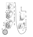
図1は本発明による化学分析装置の例を示す図である。化学分析装置1は、モータ11、モータ11により回転可能な保持ディスク12、保持ディスク12上に配置された複数の検査カートリッジ2、検査カートリッジ2に穿孔するための穿孔機13、加温装置14及び検出装置15を有する。操作者は検査項目ごとに検査カートリッジ2を用意し、保持ディスク12に装着し、化学分析装置1を起動させる。
FIG. 1 shows an example of a chemical analyzer according to the present invention. The
本例の化学分析装置では、加温装置14と検出装置15はそれぞれ別の場所に設けられているが例えば両者を一体化し、加温と検出を同一の位置で行ってもよい。また、加温装置、及び、検出装置は、保持ディスク12の上面に位置されているが、どちらか一方又は両方を保持ディスク12の下面に配置してもよい。
In the chemical analyzer of this example, the
図2を参照して検査カートリッジ2の構造を説明する。検査カートリッジ2は略6角形の薄い基板からなる。6角形の短辺が保持ディスクの回転中心の内周側に配置され、6角形の長辺が外周側に配置される。従って、以下に、6角形の短辺側を内周側、6角形の長辺側を外周と称する。
The structure of the
検査カートリッジ2は、溶解液容器220、追加液容器230、洗浄液容器240、250、260、溶離液容器270、及び、増幅液容器280、290を有する。これらの試薬容器220、230、240、250、260、270、280、290の外周側には、出口流路が設けられている。出口流路には、試薬容器の外周端から始まり内周側に折り返した後に外周側に延びる折り返し部が形成されている。
The
試薬容器220、230、240、250、260、270、280、290の内周側には、空気流路及び空気フィルタを介して穿孔部223、233、243、253、263、273、283、293が設けられている。
On the inner peripheral side of the
検査カートリッジ2には、更に、試料容器200、血球貯蔵容器210、血清定量容器211、血清反応容器310、核酸捕捉部前容器320、核酸捕捉部330、バッファー容器340、溶離液回収容器390、及び、廃液容器400が設けられている。
The
これらの容器200、210、310、320、340、390、400の内周側にも、同様に、空気流路及び空気フィルタを介して穿孔部203、213、313、323、343、393、403が設けられている。
Similarly, the
試薬容器の構造については後に詳細に説明する。試料容器200、血球貯蔵容器210、血清定量容器211、血清反応容器310、核酸捕捉部前容器320、核酸捕捉部330、バッファー容器340、溶離液回収容器390、及び、廃液容器400、出口流路、空気流路、及び、穿孔部は、検査カートリッジ2の上面に形成された凹部である。
The structure of the reagent container will be described in detail later.
検査カートリッジ2の上面には、フィルム又は薄板等で構成されるカートリッジカバーがカートリッジ上面の全体を覆うように、接着又は接合されている。従って、容器、出口流路、空気流路、空気フィルタ、及び、穿孔部は、密閉空間を形成している。
A cartridge cover made of a film, a thin plate, or the like is bonded or bonded to the upper surface of the
本例では、遠心力を利用して、流路によって互いに接続されている2つの容器間にて試薬又は溶液を移動させる。先ず、2つの容器の内周側にそれぞれ接続された穿孔部にて、カートリッジカバーを穿孔し、2つの容器を大気圧に開放する。次に、保持ディスク12を回転させることにより、容器内の試薬又は溶液は、遠心力の作用によって、内周側の容器から外周側の容器に移動する。このような操作を順次繰り返すことにより、所定の処理を実行することができる。
In this example, a reagent or a solution is moved between two containers connected to each other by a flow path using centrifugal force. First, the cartridge cover is perforated at the perforating portions connected to the inner peripheral sides of the two containers, and the two containers are opened to the atmospheric pressure. Next, by rotating the holding
尚、図1に示す化学分析装置1のように、検出装置15が保持ディスク12の上側に設けられている場合には、カートリッジカバーの材質は、検出を妨げない材質である必要がある。検出装置15が保持ディスク12の下側に設けられている場合には、検査カートリッジの底面の形状、厚さ及び、材質は、検出を妨げないものとする必要がある。
In the case where the
以下検査カートリッジ2を用いて、全血を試料として用いた場合のウイルス核酸の抽出処理を行う場合を説明する。
Hereinafter, the case where the extraction process of the viral nucleic acid when whole blood is used as a sample is performed using the
図3は化学分析装置の動作の概略を示す。図4は各動作の内容を示す。ステップS1にて、穿孔を行う。即ち、穿孔部203、213にて、カートリッジカバーを穿孔し、試料容器200及び血球貯蔵容器210を大気圧に接続する。ステップS2にて、保持ディスク12を回転させる。それによって、ステップS100にて、全血の血清を血球より分離する。ステップS100の血清分離は、図4に示すように、2つの工程を含む。ステップS101の全血流動では、試料容器200の全血は血清定量容器211及び血球貯蔵容器210に移動する。血清定量容器211と血球貯蔵容器210の間には堰が設けられている。従って、ステップS102の血清分離では、血清定量容器211内の血球は遠心力によって堰を越えて血球貯蔵容器210に移動する。血球は血球貯蔵容器210に集まり、血清は血清定量容器211に集まる。ステップS3にて、保持ディスク12の回転を停止する。
FIG. 3 shows an outline of the operation of the chemical analyzer. FIG. 4 shows the contents of each operation. In step S1, drilling is performed. That is, the cartridge cover is pierced by the piercing
ステップS4にて、穿孔部223、313にて、カートリッジカバーを穿孔し、溶解液容器220及び血清反応容器310を大気圧に接続する。ステップS5にて、保持ディスク12を回転させる。それによって、ステップS200にて、血清と溶解液は血清反応容器310にて混合する。ステップS200の混合は、図4に示すように4つの工程を含む。ステップS201の溶解液流動では、溶解液容器220の溶解液は血清反応容器310に移動する。ステップS202の血清流動では、血清定量容器211の血清は血清反応容器310に移動する。ステップS203の血清及び溶解液混合では、血清と溶解液は混合する。ステップS204にて、血清と溶解液は反応する。ステップS6にて、保持ディスク12の回転を停止する。
In step S4, the cartridge cover is pierced by the piercing
ステップS7にて、穿孔部233、393、403にて、カートリッジカバーを穿孔し、追加液容器230、溶離液回収容器390及び廃液容器400を大気圧に接続する。ステップS8にて、保持ディスク12を回転させる。それによって、ステップS300にて、核酸捕捉がなされる。ステップS300の核酸捕捉は、図4に示すように4つの工程を含む。ステップS301の追加液流動では、追加液容器230の追加液は血清反応容器310に移動する。ステップS302の混合液流動では、血清反応容器310の混合液は、追加液によって押し出され核酸捕捉部330に移動する。ステップS303の核酸捕捉部通過では、混合液は核酸捕捉部を通過する。ステップS304にて、核酸捕捉部を通過した混合液は溶離液回収容器390を経由して廃液容器400に移動する。ステップS9にて、保持ディスク12の回転を停止する。
In step S7, the cartridge cover is pierced by the piercing
次に、洗浄工程を説明する。洗浄工程は、第1、第2、及び第3洗浄工程を含む。これらの洗浄工程毎に、ステップS10〜ステップS12及びステップS400の動作を繰り返す。先ず、第1洗浄工程を説明する。ステップS10にて、穿孔部243、323にて、カートリッジカバーを穿孔し、第1洗浄液容器240及び核酸捕捉部前容器320を大気圧に接続する。ステップS11にて、保持ディスク12を回転させる。それによって、ステップS400にて、洗浄がなされる。ステップS400の洗浄は、図4に示すように3つの工程を含む。ステップS401の洗浄液流動では、第1洗浄液容器240の洗浄液は核酸捕捉部前容器320を経由して核酸捕捉部330に移動する。ステップS402にて、第1洗浄液容器240の洗浄液は核酸捕捉部前容器320及び核酸捕捉部330を洗浄する。ステップS403にて、核酸捕捉部330を通過した洗浄液は溶離液回収容器390を経由して廃液容器400に移動する。ステップS12にて、保持ディスク12の回転を停止する。
Next, the cleaning process will be described. The cleaning process includes first, second, and third cleaning processes. The operations of Steps S10 to S12 and Step S400 are repeated for each of these cleaning processes. First, the first cleaning process will be described. In step S10, the cartridge cover is pierced by the piercing
第2洗浄工程を説明する。ステップS10にて、穿孔部253にて、カートリッジカバーを穿孔し、第2洗浄液容器250を大気圧に接続する。ステップS11にて、保持ディスク12を回転させる。それによって、ステップS400にて、洗浄がなされる。以下は、第1洗浄工程と同様である。ステップS12にて、保持ディスク12の回転を停止する。
A 2nd washing | cleaning process is demonstrated. In step S10, the cartridge cover is punched by the
次に、第3洗浄工程を説明する。ステップS10にて、穿孔部263、343にて、カートリッジカバーを穿孔し、第3洗浄液容器260及びバッファー容器340を大気圧に接続する。ステップS11にて、保持ディスク12を回転させる。それによって、ステップS400にて、洗浄がなされる。ステップS401の洗浄液流動では、第3洗浄液容器260の洗浄液はバッファー容器340を経由して溶離液回収容器390に移動する。ステップS402にて、第3洗浄液容器260の洗浄液は溶離液回収容器390を洗浄する。ステップS403にて、溶離液回収容器390を洗浄した洗浄液は廃液容器400に移動する。ステップS12にて、保持ディスク12の回転を停止する。
Next, the third cleaning process will be described. In step S10, the cartridge cover is pierced by the piercing
ステップS13にて、穿孔部273にて、カートリッジカバーを穿孔し、溶離液容器270を大気圧に接続する。ステップS14にて、保持ディスク12を回転させる。それによって、ステップS500にて、溶離がなされる。ステップS500の溶離は、図4に示すように3つの工程を含む。ステップS501の溶離液流動では、溶離液容器270の溶離液は核酸捕捉部前容器320を経由して核酸捕捉部330に移動する。ステップS502にて、溶離液は核酸捕捉部330を通過し、核酸捕捉部330に捕捉された核酸を溶離する。ステップS503にて、核酸を溶離した溶離液は、溶離液回収容器390に保持される。ステップS15にて、保持ディスク12の回転を停止する。
In step S13, the cartridge cover is punched by the
ステップS16にて、穿孔部283、293にて、カートリッジカバーを穿孔し、第1増幅液容器280及び第2増幅液容器290を順次、大気圧に接続する。ステップS17にて、保持ディスク12を回転させる。それによって、ステップS600にて、増幅がなされる。ステップS600の増幅は、図4に示すように2つの工程を含む。ステップS601の増幅液流動では、第1増幅液容器280の増幅液はバッファー容器340を経由して溶離液回収容器390に移動する。第2増幅液容器290の増幅液はバッファー容器340を経由して溶離液回収容器390に移動する。ステップS602にて、溶離液回収容器390内の核酸は増幅液によって増幅される。溶離液回収容器390はこのとき加温される。ステップS19にて、保持ディスク12の回転を停止する。
In step S16, the cartridge cover is pierced by the piercing
ステップS700にて、検出を行う。溶離液回収容器390内の核酸を検出装置によって検出する。
In step S700, detection is performed. Nucleic acids in the
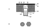
以下に、本発明の検査カートリッジに設けた試薬容器の様々な例を説明する。先ず、図5〜図8を参照して、試薬容器の第1の例を説明する。本例の試薬容器はマイクロカプセル500である。試薬を内包したマイクロカプセル500を、検査カートリッジ20の凹部に配置する。この凹部を以下に試薬ポート21と呼ぶ。
Hereinafter, various examples of the reagent container provided in the test cartridge of the present invention will be described. First, a first example of a reagent container will be described with reference to FIGS. The reagent container of this example is a
マイクロカプセル500は、膜状の被膜で液体試薬や粉末試薬を封止した小型のカプセルであり、既に、様々な分野にて使用されている。マイクロカプセル500の製造方法として、様々な方法が用いられる。例えば、試薬が油溶性の場合は液状被膜を油溶性試薬の周囲に形成し、被膜を固化させることによりマイクロカプセル500を形成することができる。試薬が水溶性の場合には、先にカプセル容器を形成し、そこに試薬を注入してから注入口を塞ぐことでマイクロカプセル500を形成することができる。
The
図5は、マイクロカプセル500を検査カートリッジ20へ装着し、検査にて使用するまでの手順を示したものである。ステップS801にて、検査カートリッジ20の試薬ポート21の各々にマイクロカプセル500を装着する。マイクロカプセル500を所定の試薬ポート21に間違い無しに配置するためには、両者に目印を設けるとよい。例えば、マイクロカプセル500の形状を、試薬毎に縦横比の異なる紡錘体にし、試薬ポート21をマイクロカプセル500の形状に対応した形状にする。それによって、マイクロカプセル500を間違った試薬ポート21に配置することが阻止される。また、試薬ポート21とマイクロカプセル500に、識別用の同一の色又は記号を付してもよい。
FIG. 5 shows a procedure until the
ステップS802にて、検査カートリッジ20の上面にカートリッジカバー30を貼付ける。ステップS803にて、検査カートリッジ20を梱包し、ステップS804にて、出荷する。ステップS805にて、出荷先にて保存し、ステップS806にて、検査カートリッジ20を検査に使用する。出荷元から出荷先まで、試薬のうち、最も管理条件が厳しい試薬に合わせて管理する。例えば、試薬の中に、低温管理が必要な試薬が含まれる場合には、その試薬に必要な温度条件に適合するように、温度管理する。そのために、温度制御が可能な保冷車501等を用いて配送し、出荷先では、保冷庫502等の環境制御機器内部で管理することが望ましい。
In step S <b> 802, the
本例によると、検査カートリッジ20の試薬は、マイクロカプセル500の被膜によって保護されているから、不必要な流出、長期保管によるコンタミネーション、及び、失活の問題を回避することができる。また、マイクロカプセル500には正確な量の試薬が封止されているから、流動性及び保持性を大幅に高めることができる。
According to this example, since the reagent of the
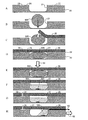
次に、図6を参照して、検査カートリッジ20に設けた試薬容器の第1の例の動作を説明する。図6Aは、検査カートリッジ20に形成された試薬ポート21を示す。試薬ポート21の内周側には穿孔部23が設けられている。穿孔部23は空気流路24を介して試薬ポート21に接続されている。試薬ポート21の外周側には出口流路22が設けられている。図6Bに示すように、先ず、試薬ポート21内に、マイクロカプセル500を配置する。図6Cに示すように、検査カートリッジ20の上面にカートリッジカバー30を貼付ける。図6Dは、カートリッジカバー30によって、試薬ポート21、穿孔部23、空気流路24、及び、出口流路22が密閉されている状態を示す。
Next, with reference to FIG. 6, the operation of the first example of the reagent container provided in the
次に、図6Eに示すように、マイクロカプセル500を破壊する。本例では、レーザ光61を、カートリッジカバー30を介して、マイクロカプセル500に照射する。それによってマイクロカプセル500は加熱され、溶解し、破壊する。マイクロカプセル500に照射するレーザ光61の強さは、マイクロカプセル500を溶解させることができるが、カートリッジカバー30を溶解しないような大きさでなければならない。
Next, as shown in FIG. 6E, the
カートリッジカバー30は、使用するレーザ光61の波長域において光の透過率が非常に高い材料によって形成される。マイクロカプセル500の被膜の少なくとも一部には、使用するレーザ光61の波長域において光の吸収率が高い材料を用いるか、光の吸収率の高い色を塗布する。
The
レーザ光61の照射の代わりに、誘導加熱を用いてもよい。この場合には、カートリッジカバー30は誘導加熱の影響を受けない材料によって形成される。マイクロカプセル500の被膜には、誘導加熱されやすい材質を用いる。レーザ光61の照射や誘導加熱の代わりに、接触式の過熱方法を使用してもよい。
Instead of irradiation with the
図6Fは、マイクロカプセル500が破壊し、内部の試薬503が試薬ポート21内に充填された状態を示す。次に、図6Gに示すように、穿孔部23にて、カートリッジカバー30を穿孔する。それによって、試薬ポート21は孔31を介して大気圧に接続される。図6Hに示すように、保持ディスク12を回転させる。試薬ポート21内の試薬503は、遠心力62によって、矢印63方向に、出口流路22を介して、外周側の容器に流動する。
FIG. 6F shows a state where the
本例の場合、マイクロカプセル500の被膜の少なくとも一部を加熱するため、マイクロカプセル500内の試薬503は、加熱によって反応性が変化するものであってはならない。例えば、高温で失活する可能性がある酵素等の試薬の場合には、本例の方法を採用することは回避したほうがよい。そのような試薬の場合には、以下に説明するように、機械的な手段によって、マイクロカプセル500を破壊する。
In the case of this example, in order to heat at least a part of the coating film of the
図7は、図6と同様に、検査カートリッジ20に設けた試薬容器の第1の例の動作を示すが、本例では、マイクロカプセル500を破壊する方法が図6の例と異なる。図7A〜図7Dは、図6A〜図6Dと同様であり、その説明を省略する。
FIG. 7 shows the operation of the first example of the reagent container provided in the
本例では、図7Eに示すように、マイクロカプセル500を針71によって破壊する。針71を、カートリッジカバー30の上から、カートリッジカバー30を貫通するように、押し込み、その下のマイクロカプセル500を突き刺す。それによってマイクロカプセル500は破壊し、内部の試薬503は試薬ポート21内に充填される。
In this example, the
図7Fに示すように、カートリッジカバー30に形成された針による孔32をシール材33によって封止する。
As shown in FIG. 7F, the
次に、図7Gに示すように、穿孔部23にて、カートリッジカバー30を穿孔する。それによって、試薬ポート21は孔31を介して大気圧に接続される。図7Hに示すように、保持ディスク12を回転させる。試薬ポート21内の試薬503は、遠心力62によって、矢印63方向に、出口流路22を介して、外周側の容器に流動する。
Next, as shown in FIG. 7G, the
本例の場合、カートリッジカバー30及びマイクロカプセル500の色や材質に特に制限はないが、針によってカートリッジカバー30に形成された孔32をシール材等で封止する必要がある。
In the case of this example, the color and material of the
図8は、図6及び図7と同様に、検査カートリッジ20に設けた試薬容器の第1の例の動作を示すが、本例では、マイクロカプセル500を破壊する方法が図6及び図7の例と異なる。図8A〜図8Dは、図6A〜図6Dと同様であり、その説明を省略する。
FIG. 8 shows the operation of the first example of the reagent container provided in the
図8E〜図8Gは、穿孔部23と出口流路を含まない垂直面に沿って検査カートリッジ20を切断した断面図である。
8E to 8G are cross-sectional views of the
本例では、図8Eに示すように、マイクロカプセル500を針81によって破壊するが、針81は、予め、検査カートリッジ20内に内蔵されている。即ち、試薬ポート21の内壁に通ずる水平方向の穴80が設けられ、この穴に可動な針が設けられている。針は、適当の駆動装置によって、軸線方向に移動することができる。針の駆動装置には、空気バネによって針をピストン状に往復運動させる空気バネ機構、磁力によって針を往復運動させる磁力機構、等であってよい。針及びその駆動装置は、ユニット化されてよい。このユニットは、検査カートリッジ20に形成されたザグリ孔に圧入され、封止されてよい。
In this example, as shown in FIG. 8E, the
図8Fに示すように、針81の駆動装置82を駆動することによって、針81を試薬ポート21内に突き出す。突き出た針によって、マイクロカプセル500は破壊する。針の駆動装置82が、空気バネ機構を含む場合には、空気バネ内の空気を加熱することにより、膨張させる。それにより、空気バネは伸張する。針81の駆動装置82が磁力機構を含む場合には、磁界を生成し、生成した磁界によって針を移動させる。
As shown in FIG. 8F, the
図8Gは、マイクロカプセル500が破壊し、内部の試薬503が試薬ポート21内に充填された状態を示す。図8H及び図8Iは、穿孔部23と出口流路22を含む垂直面に沿って検査カートリッジ20を切断した断面図である。図8Hに示すように、穿孔部23にて、カートリッジカバー30を穿孔する。それによって、試薬ポート21は孔31を介して大気圧に接続される。図8Iに示すように、保持ディスク12を回転させる。試薬ポート21内の試薬503は、遠心力62によって、矢印63方向に、出口流路22を介して、外周側の容器に流動する。
FIG. 8G shows a state in which the
本例によると、針の駆動装置の構造が複雑となるが、マイクロカプセル500を加熱する必要がなく、また、検査カートリッジ20に形成された孔を封止する必要がない利点がある。
According to this example, the structure of the needle driving device is complicated, but there is an advantage that it is not necessary to heat the
次に、図9〜図16を参照して、試薬容器の第2の例を説明する。本例によると、マイクロカプセル500の代わりに、蓋付の密閉容器を用いる。このような試薬入り密閉容器を検査カートリッジ20の試薬ポート21に配置する。尚、試薬入り密閉容器を検査カートリッジ20の試薬ポート21に配置し、両者を接着剤、超音波、熱等による溶着等によって接着又は固定してもよい。
Next, a second example of the reagent container will be described with reference to FIGS. According to this example, a sealed container with a lid is used instead of the
このような密閉容器の例として、市販のプリンやヨーグルトの容器として用いられるプラスチック製の密閉容器があるが、それに限定されない。密閉容器の材料、即ち、蓋材及び容器の材料は、検査カートリッジの熱膨張係数と同一又は近似した熱膨張係数を有する材料がよい。 Examples of such sealed containers include, but are not limited to, plastic sealed containers used as commercially available pudding and yogurt containers. The material of the closed container, that is, the material of the lid and the container is preferably a material having the same or approximate thermal expansion coefficient as that of the inspection cartridge.
例えば、密閉容器の材料の熱膨張係数が検査カートリッジの熱膨張係数より大きい場合には、検査カートリッジ20の試薬ポート21に配置された試薬容器は熱膨張により試薬ポート21の内壁に押圧され、変形又は破壊する可能性がある。逆に、密閉容器の材料の熱膨張係数が検査カートリッジの熱膨張係数より小さい場合には、試薬容器と試薬ポート21の内壁の間に隙間が生成され、カートリッジカバーを穿孔すると、その隙間に試薬が進入する可能性がある。また、試薬容器を検査カートリッジ20の試薬ポート21に接着剤又は溶着によって接着した場合には、熱膨張量の差に起因して接着部が剥離する可能性がある。密閉容器の熱膨張係数が検査カートリッジの熱膨張係数と同一又は近似している場合には、熱膨張量の差に起因するこのような事態は生じない。
For example, when the thermal expansion coefficient of the material of the sealed container is larger than the thermal expansion coefficient of the test cartridge, the reagent container disposed in the
密閉容器の材料は、長期間保存しても内部の試薬が変化しないものがよい。従って、気密性があり且つ試薬と反応しない材料がよい。このような条件を満たす限り、密閉容器は、プラスチック、樹脂、ガラス、紙、金属、表面に樹脂膜を施した金属等、どのような材料によって形成されてもよく、成型加工、切削加工等、どのような加工方法によって製造されてもよい。また、蓋材は、容器と同一の材料であってもよいが、上述の食べ物を収容する密閉容器のように、容器と異なる材料であってもよい。 The material of the sealed container is preferably a material whose internal reagent does not change even when stored for a long period of time. Therefore, a material that is airtight and does not react with the reagent is preferable. As long as these conditions are satisfied, the sealed container may be formed of any material, such as plastic, resin, glass, paper, metal, metal with a resin film on the surface, molding, cutting, etc. It may be manufactured by any processing method. The lid material may be the same material as the container, but may be a different material from the container, such as a sealed container that contains the above-described food.
蓋材は、検査カートリッジの熱膨張係数と同一又は近似した熱膨張係数を有する材料であり、且つ、気密性があり試薬と反応しない材料がよい。光学的方法によって穿孔する場合であって、白色光源(ハロゲンランプ等)を用いる場合には、蓋材の表面に黒化処理を施し、光の吸収率を増加させる必要があるが、レーザ光のように特定の波長の光源を用いる場合には、その光源の波長を含む領域に吸収率のピークがある材料を用いる。この場合、このような波長領域において透明な被膜を設けてもよい。以下の例では、アルミ系の封止材を用いるが、これに限定されるものではない。 The lid member is preferably a material having a thermal expansion coefficient that is the same as or close to that of the test cartridge, and is airtight and does not react with the reagent. When drilling by an optical method and using a white light source (such as a halogen lamp), it is necessary to blacken the surface of the lid to increase the light absorption rate. Thus, when a light source having a specific wavelength is used, a material having an absorption peak in a region including the wavelength of the light source is used. In this case, a transparent film may be provided in such a wavelength region. In the following example, an aluminum-based sealing material is used, but the present invention is not limited to this.
図9を参照して、試薬入り密閉容器の製造方法を説明する。本例の試薬入り密閉容器の形状は、円筒、角筒、倒立円錐台、倒立角錐台等の様々な形状が可能であるが、以下では、倒立円錐台の場合を説明する。密閉容器の外部形状は、検査カートリッジの試薬ポートに装着し易いように選択される。密閉容器を底面から検査カートリッジの試薬ポートに挿入する場合には、底面の面積は上面の面積より小さいか又は等しい必要がある。倒立円錐台の場合、面積が小さい底面から試薬ポートに挿入する。また、容器の角部は面取り加工されてよい。密閉容器の内部形状は、内部の試薬が完全に流出し易いように、底面の面積は上面の面積より小さいほうがよい。 With reference to FIG. 9, the manufacturing method of the airtight container containing a reagent is demonstrated. Various shapes such as a cylinder, a rectangular tube, an inverted truncated cone, and an inverted truncated pyramid can be used as the shape of the closed container containing the reagent of this example. Hereinafter, the case of the inverted truncated cone will be described. The external shape of the sealed container is selected so that it can be easily attached to the reagent port of the test cartridge. When the sealed container is inserted into the reagent port of the test cartridge from the bottom surface, the area of the bottom surface needs to be smaller than or equal to the area of the top surface. In the case of an inverted truncated cone, it is inserted into the reagent port from the bottom having a small area. Further, the corners of the container may be chamfered. As for the internal shape of the sealed container, the area of the bottom surface should be smaller than the area of the top surface so that the reagent inside can easily flow out.
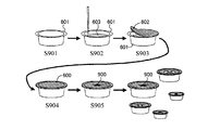
ステップS901にて、容器本体601を用意する。長時間経過しても、容器と外部環境の間にて、試薬、水分、空気等が透過しないように、容器の内面に適当な表面処理を施すか、又は、容器の材質として気密性が高いものを使用する。ステップS902にて、試薬603を分注する。試薬603は、容器本体601が満杯とならないように液面上に空間が形成されるように、適当な量を分注する。
In step S901, a
ステップS903にて、蓋材602を貼り付け、ステップS904にて、蓋材602を容器本体601に接着する。蓋材602は、例えば医薬品の梱包に用いられるアルミ系の封止材を用いる。この封止材を容器の端面に超音波、熱等による溶着等の方法により固定する。それにより、試薬が密閉された容器が完成する。
In step S903, the
好ましくは、ステップS902の試薬分注、ステップS903の蓋の貼り付け及びステップS904の蓋の接着は、真空中又は不活性ガス雰囲気中で行う。従って、密閉された容器内は、真空であるか又は不活性ガスが密封される。 Preferably, the reagent dispensing in step S902, the attachment of the lid in step S903, and the adhesion of the lid in step S904 are performed in a vacuum or an inert gas atmosphere. Therefore, the sealed container is evacuated or sealed with an inert gas.
ステップS905にて、試薬入り密閉容器600の外面に、試薬の種類を識別するための識別標識900を付与する。識別標識900が印刷された蓋材を用いてもよい。識別標識900は、文字、記号、色彩等を含む。
In step S905, an
図10は、試薬入り密閉容器600を検査カートリッジ20の試薬ポート21に装着する方法を示す。試薬ポート21の底面又は縁には、試薬の種類を識別するための識別標識901が付与されている。試薬入り密閉容器600に付された識別標識900と試薬ポート21に付された識別標識902が同一となるように、試薬入り密閉容器600を試薬ポート21に装着する。蓋材602に非接触型RF−IDタグを取り付けておき、それを化学分析装置1によって検出してもよい。試薬入り密閉容器600と試薬ポート21は接着剤、超音波、熱等による溶着等によって互いに接着され固定されてよい。
FIG. 10 shows a method for attaching the reagent-containing sealed
図11と図12は、試薬ポート21と試薬入り密閉容器600の形状をそれぞれ変えることによって装着ミスを防止する方法を示す。図11に示すように、検査カートリッジ20に形成された試薬ポート21は、試薬毎に異なる形状を有し、例えば、円形の周囲に放射状の楔形の凹部25を設けられた形状、多角形、楕円、非円形等の形状を有する。
FIG. 11 and FIG. 12 show a method of preventing mounting mistakes by changing the shapes of the
図12は、検査カートリッジ20に形成された試薬ポート21とそれに装着する試薬入り密閉容器600の形状の例を示す。図12A及び図12Bに示すように、試薬ポート21の形状が、円形の周囲に放射状の楔形の凹部25を有する場合、試薬入り密閉容器600の本体601は、倒立円錐台の周囲に放射状の突起605を有する。図12C及び図12Dに示すように、試薬ポート21が所定の形状を有する場合には、試薬入り密閉容器600の本体601の外形はそれに対応した形状を有する。こうして、試薬毎に、試薬ポート21と試薬入り密閉容器の形状が異なるため、試薬入り密閉容器を正しくない試薬ポート21に配置することが防止される。
FIG. 12 shows an example of the shape of the
図11と図12には、試薬ポート21と試薬入り密閉容器の形状の一例を示したが、他の形状も可能である。例えば、試薬入り密閉容器が倒立円錐台の場合、その周囲に、異なる数の突起を設けてもよいが、突起の間隔を不均一にしてもよい。尚、本例の試薬ポート21と試薬入り密閉容器に、図9及び図10にて説明した識別標識を付してもよい。
11 and 12 show an example of the shape of the
図13は、図5と同様、本例の試薬入り密閉容器が装着された検査カートリッジの出荷から検査までの作業の流れを示したものである。ステップS1301にて、検査カートリッジ20の試薬ポート21の各々に試薬入り密閉容器600を装着する。ステップS1302にて、検査カートリッジ20の上面にカートリッジカバー30を貼付ける。ステップS1303にて、検査カートリッジ20を梱包する。ステップS1304にて、温度制御が可能な保冷車501等を用いて出荷する。ステップS1305にて、出荷先にて保冷庫502等の環境制御機器内に保存する。ステップS1306にて、検査カートリッジ20を検査に使用する。本例においても、検査作業者は例えば全血などの試料以外の分注作業をする必要がないため、流動不安定のリスクを低減できる。
FIG. 13 shows the flow of work from shipment to inspection of the inspection cartridge equipped with the reagent-containing airtight container of this example, as in FIG. In step S1301, the reagent-containing sealed
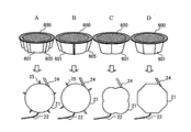
図14を参照して、検査カートリッジ20に設けた試薬容器の第2の例の動作を説明する。図14Aは、検査カートリッジ20に形成された試薬ポート21を示す。本例の試薬ポート21の形状は、試薬入り密閉容器600の形状に対応して、倒立円錐台である。試薬ポート21の内周側には穿孔部23が設けられている。穿孔部23は空気流路24を介して試薬ポート21に接続されている。試薬ポート21の外周側には出口流路22が設けられている。図14Bに示すように、先ず、試薬ポート21に試薬入り密閉容器600を配置する。試薬入り密閉容器600は本体601、蓋材602及び試薬603を有する。
The operation of the second example of the reagent container provided in the
図14Cに示すように、検査カートリッジ20の上面にカートリッジカバー30を貼付ける。図14Dは、カートリッジカバー30によって、試薬ポート21、穿孔部23、空気流路24、及び、出口流路22が密閉されている状態を示す。
As illustrated in FIG. 14C, the
次に、図14Eに示すように、試薬入り密閉容器の蓋材602に孔を形成する。本例では、レーザ光61を、カートリッジカバー30を介して、試薬入り密閉容器600の蓋材602に照射する。それによって蓋材602の一部が加熱され、溶解し、そこに孔が形成される。蓋材602に照射するレーザ光61の強さは、蓋材602を溶解させることができるが、カートリッジカバー30を溶解しないような大きさでなければならない。図6の例と同様に、レーザ光61の照射の代わりに、誘導加熱を用いてもよい。
Next, as shown in FIG. 14E, holes are formed in the
本例では、密閉容器内の試薬の液面上に空間が設けられている。即ち、試薬の液面は、蓋材より離れている。従って、蓋材を加熱して溶解させても、試薬が加熱されることはない。従って、試薬が劣化することはない。蓋材を、レーザ光61の吸収率が高い材料によって構成することによって、最小限のレーザ光61によって、蓋材を溶解することができる。蓋材に識別標識を付した場合には、識別標識を、黒色等のエネルギー吸収性の高い塗料によって形成してよい。
In this example, a space is provided on the liquid level of the reagent in the sealed container. That is, the liquid level of the reagent is separated from the lid material. Therefore, even if the lid member is heated and dissolved, the reagent is not heated. Therefore, the reagent does not deteriorate. By configuring the lid member with a material having a high absorption rate of the
図14Fは、蓋材602の一部が溶解し、孔605が形成された状態を示す。次に、図14Gに示すように、穿孔部23にて、カートリッジカバー30を穿孔する。それによって、容器内の試薬603は孔31を介して大気圧に接続される。図14Hに示すように、保持ディスク12を回転させる。容器内の試薬603は、遠心力62によって、矢印63方向に、蓋材602の孔605より流出し、出口流路22を介して、外周側の容器に流動する。
FIG. 14F shows a state in which a part of the
図15は、図14と同様に、検査カートリッジ20に設けた試薬容器の第2の例の動作を示すが、本例では、蓋材に孔を形成する方法が図14の例と異なる。図15A〜図15Dは、図14A〜図14Dと同様であり、その説明を省略する。
FIG. 15 shows the operation of the second example of the reagent container provided in the
本例では、図15Eに示すように、蓋材602に針71に突き刺す。針71を、カートリッジカバー30の上から、カートリッジカバー30を貫通するように、押し込み、その下の試薬入り密閉容器600の蓋材602を突き刺す。それによって蓋材602に孔605が形成される。
In this example, as shown in FIG. 15E, the
図15Fに示すように、カートリッジカバー30に形成された針による孔32をシール材33によって封止する。
As shown in FIG. 15F, the
次に、図15Gに示すように、穿孔部23にて、カートリッジカバー30を穿孔する。それによって、容器内の試薬603は孔31を介して大気圧に接続される。図15Hに示すように、保持ディスク12を回転させる。容器内の試薬603は、遠心力62によって、矢印63方向に、蓋材602の孔605より流出し、出口流路22を介して、外周側の容器に流動する。
Next, as shown in FIG. 15G, the
図16は、図14及び図15と同様に、検査カートリッジ20に設けた試薬容器の第2の例の動作を示すが、本例では、蓋材に孔を形成する方法が図14及び図15の例と異なる。図16A〜図16Bは、図14A〜図14Bと同様であり、その説明を省略する。
FIG. 16 shows the operation of the second example of the reagent container provided in the
図16Cに示すように、本例によると、カートリッジカバー30の下面に突起34を形成する。図16Dに示すように、突起34を有するカートリッジカバー30を検査カートリッジ20の上面に貼付ける。このとき、突起34が、試薬入り密閉容器の蓋材602の上に配置されるように、突起34を形成する。カートリッジカバー30によって、試薬ポート21、穿孔部23、空気流路24、及び、出口流路22が密閉される。
As shown in FIG. 16C, according to this example, the
図16Eに示すように、突起34が設けられている位置にて、カートリッジカバー30を上から下に押圧161する。それによって、突起34が蓋材602に押し付けられ、蓋材602に孔605が形成される。図16Fは、試薬入り密閉容器の蓋材602に孔605が形成された状態を示す。図16G及び図16Hは、図15G及び図15Hと同様である。
As shown in FIG. 16E, the
尚、図14〜図16の例において、蓋材602に形成する孔605は、蓋材602の中心位置よりも出口流路22に近いほうがよい。即ち、蓋材602に形成する孔605は、蓋材の中心位置より外周側に偏奇した位置に形成したようがよい。
14 to 16, the
次に、図17〜図22を参照して、試薬容器の第3の例を説明する。図17に示すように、本例の捩じ込み式試薬密閉容器700は、円筒状の容器本体701と蓋材702からなり、内部に試薬703が収容されている。また、容器の上部の周囲にはネジ部704が形成されており、その下に外周に沿って延びる突起705が形成されている。
Next, a third example of the reagent container will be described with reference to FIGS. As shown in FIG. 17, a screw-in type reagent sealed
図18は、本例の試薬容器700を検査カートリッジ20に装着する方法を示す。本例では、検査カートリッジ20に貫通孔が形成され、この貫通孔が試薬ポート21である。貫通孔の内部には、試薬密閉容器700のネジ部704に対応したネジ部26が形成され、その端部に段差28が形成されている。内部に試薬が内包された試薬密閉容器700を、検査カートリッジ20の下面から、試薬ポート21に挿入し、試薬密閉容器700のネジ部704を、試薬ポート21ネジ部26に係合させる。試薬密閉容器700が試薬ポート21内を進むと、試薬密閉容器700の突起705が試薬ポート21の段差28に係合する。それにより、試薬密閉容器700は検査カートリッジ20に装着されると共に、試薬ポート21内は完全に密閉される。試薬密閉容器700と試薬ポート21は接着剤、超音波、熱等による溶着等によって互いに接着され固定されてよい。尚、試薬容器の第3の例では、ねじによって試薬容器700を試薬ポート21に装着するが、ねじを使用しないで、接着剤、超音波、熱等による溶着等のみによって固定してもよい。
FIG. 18 shows a method of mounting the
検査カートリッジ20の上面には、穿孔部23、空気流路24及び出口流路22が設けられている。穿孔部23は、試薬ポート21の内周側に設けられ、出口流路22は試薬ポート21の外周側に設けられている。空気流路24及び出口流路22は試薬ポート21に接続されている。試薬密閉容器700を試薬ポート21に装着すると、試薬密閉容器700の蓋材702とカートリッジカバー30の間には空間が形成される。この空間は、空気流路24及び出口流路22に接続されている。この空間は、穿孔部23、空気流路24及び出口流路22と共に、カートリッジカバー30によって完全に密閉されている。
On the upper surface of the
検査カートリッジ20の試薬ポート21の周囲には、識別標識27が設けられている。一方、試薬密閉容器700にも、試薬ポート21の識別標識27に対応した識別標識記号が設けられる。これらの識別標識は、文字、記号、色彩等であってよいが、特定の形状であってもよい。それによって、試薬密閉容器を正しくない試薬ポート21に装着することが防止される。尚、識別標識を用いる代わりに、試薬毎に、試薬密閉容器及び試薬ポートの径を変化させてもよい。径が互いに異なる雄ネジと雌ネジを係合させることはできないから、試薬密閉容器を正しくない試薬ポート21に装着することが防止される。
An
図18Bに示すように試薬密閉容器700の底面には、ドライバが係合するための十字型溝、又は、レンチが係合するための6角形の頭部が形成されている。従って、ドライバ、スパナ等の工具を使用して、試薬密閉容器700を試薬ポート21に係合させることができる。
As shown in FIG. 18B, a cross-shaped groove for engaging the driver or a hexagonal head for engaging the wrench is formed on the bottom surface of the reagent
図19を参照して、本例の試薬密閉容器の製造方法及び出荷方法を説明する。ステップS1901にて、容器本体を用意する。容器本体の上端の外周にはネジ部704が形成されている。図示の容器本体は、縦長の円筒形であるが、縦長の円筒形以外の形状であってもよい。しかしながら、遠心力によって容器内の試薬が流出し易いように、容器の内径は底部から開口部に向かって大きくなるように構成する。従って、容器の内壁にテーパを設けたほうがよい。例えば、図示のように、容器の内壁と開口部を通る平面がなす角θは、90度より大きい。また、試薬密閉容器と検査カートリッジの間の気密性を確保するためには、ネジ部704の外径が、開口部に向かって小さくなるように構成する。例えば、図示のように、ネジ部704の外面と開口部を通る平面がなす角Φは、90度より大きい。
With reference to FIG. 19, the manufacturing method and shipping method of the reagent sealed container of this example are demonstrated. In step S1901, a container body is prepared. A
尚、図9〜図16に示した試薬容器の第2の例と同様に、本例の場合も、長時間経過しても、容器と外部環境の間にて、試薬、水分、空気等が透過しないように、容器の内面に適当な表面処理を施すか、又は、容器の材質として気密性が高いものを使用する。 As in the second example of the reagent container shown in FIGS. 9 to 16, in this example as well, reagent, moisture, air, etc. remain between the container and the external environment even after a long time. Appropriate surface treatment is performed on the inner surface of the container so as not to permeate, or a highly airtight material is used for the container.
ステップS1902にて、試薬703を分注する。試薬703は、容器本体701が満杯とならないように液面上に空間が形成されるように、適当な量を分注する。
In step S1902, the
ステップS1903にて、蓋材702を貼り付け、ステップS1904にて、蓋材702を容器に接着する。蓋材702は、例えば医薬品の梱包に用いられるアルミ系の封止材を用いる。この封止材を容器の端面に溶着等の方法により固定する。それにより、試薬密閉容器700が完成する。好ましくは、ステップS1902の分注、ステップS1903の貼り付け及びステップS1904の接着は、真空中又は不活性ガス雰囲気中で行う。従って、試薬密閉容器内は、真空であるか又は不活性ガスが密封される。
In step S1903, the
ステップS1905にて、試薬密閉容器と検査カートリッジを梱包する。本例では、試薬密閉容器を検査カートリッジに装着しないで、梱包する。ステップS1906にて、保冷車501等を用いて出荷する。ステップS1907にて、出荷先にて、保冷庫502等にて保存する。ステップS1908にて、出荷先の検査機関にて使用する。本例では、使用前に、試薬密閉容器を検査カートリッジの装着する。次に、試料を検査カートリッジに分注し、生化学検査装置の回転ディスクに装着する。
In step S1905, the reagent sealed container and the inspection cartridge are packed. In this example, the reagent sealed container is packed without being attached to the test cartridge. In step S1906, the vehicle is shipped using the
こうして本例では、使用前に、試薬密閉容器を検査カートリッジに装着する。これは、次のような理由による。試薬によっては、検査直前に昇温させたり攪拌したりして反応性を高める必要のあるものや、逆に、攪拌したり昇温させたりしない方がよいものなど、様々なものがある。試薬密閉容器を検査カートリッジに装着した状態にて、出荷すると、このような異なる取り扱いを要求する試薬の管理が不十分となる。そこで、試薬密閉容器を検査カートリッジとは別個に管理することにより、試薬の適性に応じた管理が可能となる。 Thus, in this example, the reagent sealed container is attached to the test cartridge before use. This is due to the following reason. Depending on the reagent, there are various types, such as those that need to be heated up or stirred just before the test to increase the reactivity, and conversely, those that should not be stirred or heated up. If the reagent sealed container is shipped in a state where it is mounted on the test cartridge, the management of the reagent requiring such different handling becomes insufficient. Therefore, by managing the reagent sealed container separately from the test cartridge, management according to the suitability of the reagent becomes possible.
使用者側における試薬密閉容器の誤装着を防止するために、試薬密閉容器に、試薬の種類を識別するための識別標識が付される。識別標識は、蓋材、容器本体の側面、又は、容器本体の底面に設けられるが、識別標識は、文字、記号、色彩、形状等を含む。 In order to prevent erroneous mounting of the reagent sealed container on the user side, an identification mark for identifying the type of reagent is attached to the reagent sealed container. The identification mark is provided on the lid member, the side surface of the container main body, or the bottom surface of the container main body, and the identification mark includes characters, symbols, colors, shapes, and the like.
更に、本例では、試薬密閉容器を検査カートリッジの下面から装着するため、検査カートリッジの上面にカートリッジカバー30を接着した状態にて、出荷することができる。使用者は、使用前に、検査カートリッジの上面にカートリッジカバー30を接着する必要はない。
Further, in this example, since the reagent sealed container is mounted from the lower surface of the test cartridge, it can be shipped with the
図20を参照して、検査カートリッジ20に設けた試薬容器の第3の例の動作を説明する。図20Aは、検査カートリッジ20に形成された試薬ポート21に、試薬密閉容器700を装着する状態を示す。試薬密閉容器700を検査カートリッジ20の下面から試薬ポート21に挿入し、試薬密閉容器700の雄ネジ部704を試薬ポート21の雌ネジ部26に係合させる。
The operation of the third example of the reagent container provided in the
上述のように、試薬密閉容器700に付された識別標識と試薬ポート21に付された識別標識が同一となるように、試薬密閉容器700を試薬ポート21に装着する。
As described above, the reagent sealed
図20Bに示すように、試薬密閉容器700の蓋材702に孔708を形成する。本例では、レーザ光61を、カートリッジカバー30を介して、試薬密閉容器の蓋材702に照射する。それによって蓋材702の一部が加熱され、溶解し、そこに孔708が形成される。蓋材702に照射するレーザ光61の強さは、蓋材702を溶解させることができるが、カートリッジカバー30を溶解しないような大きさでなければならない。図6の例と同様に、レーザ光61の照射の代わりに、誘導加熱を用いてもよい。
As shown in FIG. 20B, a
本例では、試薬密閉容器700内の試薬703の液面上に空間が設けられている。即ち、試薬703の液面は、蓋材702より離れている。従って、蓋材702を加熱して溶解させても、試薬が加熱されることはない。従って、試薬が劣化することはない。蓋材702を、レーザ光61の吸収率が高い材料によって構成することによって、最小限のレーザ光61によって、蓋材を溶解することができる。蓋材702に識別標識を付した場合には、識別標識を、黒色等のエネルギー吸収性の高い塗料によって形成してよい。
In this example, a space is provided on the liquid level of the
図20Cは、蓋材702の一部が溶解し、孔708が形成された状態を示す。次に、図20Dに示すように、穿孔部23にて、カートリッジカバー30を穿孔する。それによって、容器内の試薬は孔31を介して大気圧に接続される。図20Eに示すように、保持ディスク12を回転させる。容器内の試薬は、遠心力62によって、矢印63方向に、蓋材702の孔708より流出し、出口流路22を介して、外周側の容器に流動する。
FIG. 20C shows a state in which a part of the
図21は、図20と同様に、検査カートリッジ20に設けた試薬容器の第3の例の動作を示すが、本例では、蓋材に孔を形成する方法が図20の例と異なる。本例では、蓋材に孔を形成する方法は、図15の例と同様である。図21Aは、図20Aと同様であり、試薬密閉容器700を検査カートリッジ20に装着した状態を示す。
FIG. 21 shows the operation of the third example of the reagent container provided in the
図21Bに示すように、蓋材702に針71に突き刺す。針71を、カートリッジカバー30の上から、カートリッジカバー30を貫通するように、押し込み、その下の試薬密閉容器700の蓋材702を突き刺す。それによって蓋材702に孔708が形成される。
As shown in FIG. 21B, the
図21Cに示すように、カートリッジカバー30に形成された孔32をシール材33によって封止する。次に、図21Dに示すように、穿孔部23にて、カートリッジカバー30を穿孔する。それによって、容器内の試薬は孔31を介して大気圧に接続される。図21Eに示すように、保持ディスク12を回転させる。試薬密閉容器内の試薬703は、遠心力62によって、矢印63方向に、蓋材702の孔708より流出し、出口流路を介して、外周側の容器に流動する。
As shown in FIG. 21C, the
図22は、図20及び図21と同様に、検査カートリッジ20に設けた試薬容器の第3の例の動作を示すが、本例では、蓋材に孔を形成する方法が図20及び図21の例と異なる。本例では、蓋材に孔を形成する方法は、図16の例と同様である。
FIG. 22 shows the operation of the third example of the reagent container provided in the
図22Aは、図21Aと同様であり、試薬容器を検査カートリッジ20に装着した状態を示す。本例によると、カートリッジカバー30の下面に突起34を形成する。突起34は、試薬密閉容器700の蓋材702の上に配置されるように、形成する。
FIG. 22A is the same as FIG. 21A and shows a state where the reagent container is mounted on the
図22Bに示すように、突起34が設けられている位置にて、カートリッジカバー30を上から下に押圧161する。それによって、突起34が蓋材702に押し付けられ、蓋材702に孔708が形成される。図22Cは、試薬密閉容器700の蓋材702に孔708が形成された状態を示す。
As shown in FIG. 22B, the
図22Dに示すように、穿孔部23にて、カートリッジカバー30を穿孔する。それによって、容器内の試薬は孔31を介して大気圧に接続される。図22Eに示すように、保持ディスク12を回転させる。容器内の試薬は、遠心力62によって、矢印63方向に、蓋材702の孔708より流出し、出口流路22を介して、外周側の容器に流動する。
As shown in FIG. 22D, the
尚、図20〜図22の例において、蓋材702に形成する孔708は、蓋材の中心位置よりも出口流路22に近いほうがよい。即ち、蓋材に形成する孔は、蓋材の中心位置より外周側に偏奇した位置に形成したようがよい。
20 to 22, the
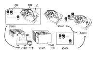
図23と図24を参照して、本発明による検査カートリッジの他の例を説明する。本例では、図23に示すように、図9〜図16の試薬入り密閉容器600と図7〜図22の捩じ込み式試薬密閉容器700の両者を1つの検査カートリッジに装着する。本例では、検査前に特殊な前処理を必要とする試薬は捩じ込み式試薬密閉容器700に分注し、検査カートリッジに装着しないで梱包する。一方、検査前に前処理を必要としない試薬は試薬入り密閉容器600に封入して予め検査カートリッジ20に装着してから梱包する。
With reference to FIGS. 23 and 24, another example of the inspection cartridge according to the present invention will be described. In this example, as shown in FIG. 23, both the reagent-containing sealed
図24は、本例の検査カートリッジ20を梱包し、出荷し、検査にて使用するまでの手順を示したものである。ステップS2401にて、検査前に前処理を必要としない試薬が封入された試薬入り密閉容器600のみを検査カートリッジ20に装着し、検査前に前処理を必要とする試薬を封入した試薬密閉容器700は検査カートリッジ20に装着しないで、梱包する。ステップS2402にて、保冷車501等にて配送し、ステップS2403にて、出荷先にて、保冷庫502等にて保存する。ステップS2404にて、検査機関等において、試薬密閉容器700に封入された試薬に対して所定の前処理を行う。ステップS2405にて、試薬密閉容器700を検査カートリッジ20に装着し、ステップS2406にて、検査カートリッジ20を保持ディスク12に装着し、保持ディスク12を回転させる。
FIG. 24 shows a procedure from packing the
尚、捩じ込み式試薬密閉容器700は、検査作業者が検査カートリッジに装着するため、捩じ込み式試薬密閉容器700及びそれに対応した試薬ポートには、誤装着を防止するための手段が講じられている。このような手段は、上述のように、所定の識別標識を捩じ込み式試薬密閉容器700と試薬ポートに設けてもよいが、試薬毎に異なる形状又は寸法を用いてもよい。
Since the screw-in type reagent sealed
こうして、特殊な前処理を必要とする試薬と前処理を特に必要としない試薬を異なる形式の容器に分注することにより、両者の取り違えの事故を防止することができる。尚、捩じ込み式試薬密閉容器は、検査作業者側で検査カートリッジに装着するため、試薬密閉容器とその試薬ポート21には識別標識を付する必要がある。
In this way, by dispensing a reagent that requires special pretreatment and a reagent that does not require pretreatment into different types of containers, it is possible to prevent a misunderstanding between the two. Since the screw-in type reagent sealed container is mounted on the test cartridge on the inspection operator side, it is necessary to attach an identification mark to the reagent sealed container and its
本発明によると、予め試薬容器を検査カートリッジに装着し、カートリッジカバーによって封止して梱包するから、検査対象毎の試薬・カートリッジキットとして取り扱うことができる。 According to the present invention, since the reagent container is mounted on the inspection cartridge in advance and sealed and packed by the cartridge cover, it can be handled as a reagent / cartridge kit for each inspection object.
一方、検査作業者は、全血を分注するのみで、試薬分注作業を省略して、検査を実施できる。 On the other hand, the inspection operator can perform the inspection by simply dispensing the whole blood, omitting the reagent dispensing operation.
本発明によると、構造が簡単なカートリッジとそれを用いた化学分析装置を提供することができ、検査作業者の作業起因の流動不安定性や検査に対する阻害要因を排除することができる。 According to the present invention, it is possible to provide a cartridge with a simple structure and a chemical analysis apparatus using the cartridge, and it is possible to eliminate flow instability caused by the work of the inspection worker and an obstruction factor for the inspection.
以上、本発明の例を説明したが、本発明は上述の例に限定されるものではなく、特許請求の範囲に記載された発明の範囲にて様々な変更が可能であることは当業者に理解されよう。 The example of the present invention has been described above, but the present invention is not limited to the above-described example, and various modifications can be made by those skilled in the art within the scope of the invention described in the claims. It will be understood.
1…化学分析装置、2…検査カートリッジ、11…モータ、12…保持ディスク、13…穿孔機、14…加温装置、15…検出装置、210…試料容器、211…血球貯蔵容器、212…血清定量容器、215…全血廃棄容器、220…溶解液容器、230…追加液容器、240…第1洗浄液容器、250…第2洗浄液容器、260…溶離液容器、270…第3洗浄液容器、280…第1検出試薬容器、290…第2検出試薬容器、301…核酸捕捉部、310…混合容器、320…反応容器、330…追い出し液容器、340…検出容器、350…第2検出試薬容器、360…第2検出試薬溶解試薬容器、390…溶離液回収容器、400…廃液貯蔵容器
DESCRIPTION OF
Claims (23)
上記検査カートリッジは、上記基板に形成された試薬ポートと該試薬ポートに配置された試薬が封入された密閉容器とを有することを特徴とする化学分析装置。 A holding disk that is rotatable about a rotation axis passing through the center, and a removable inspection cartridge held on the holding disk, the inspection cartridge including a substrate having a container and a flow path, the container and A cover for covering the flow path, and utilizing the centrifugal force generated by the rotation of the holding disk, the container on the inner peripheral side with respect to the rotation axis is connected to the rotation axis via the flow path. On the other hand, in the chemical analyzer configured to move the solution to the outer peripheral container,
The test cartridge includes a reagent port formed on the substrate and a sealed container in which a reagent arranged in the reagent port is sealed.
上記基板に形成された試薬ポートと該試薬ポートに配置された試薬が封入された密閉容器とを有することを特徴とする化学分析カートリッジ。 A substrate having a container and a flow path, and a cover covering the container and the flow path, and utilizing a centrifugal force generated by rotation around a rotation axis perpendicular to the substrate, with respect to the rotation axis In the chemical analysis cartridge configured to move the solution from the inner peripheral container to the outer peripheral container with respect to the rotation axis via the flow path,
A chemical analysis cartridge comprising: a reagent port formed on the substrate; and a sealed container in which a reagent disposed in the reagent port is sealed.
Priority Applications (3)
| Application Number | Priority Date | Filing Date | Title |
|---|---|---|---|
| JP2005129544A JP2006308366A (en) | 2005-04-27 | 2005-04-27 | Chemical analyzer and chemical analysis cartridge |
| DE102006019101A DE102006019101A1 (en) | 2005-04-27 | 2006-04-25 | Chemical substance e.g. nucleic acid, analyzer, has cartridge with reagent port formed in base plate, where closed vessel placed in port contains reagent that requires no pretreatment prior to start of test |
| US11/411,159 US20060245972A1 (en) | 2005-04-27 | 2006-04-26 | Chemical analyzer and cartridge for chemical analyzer |
Applications Claiming Priority (1)
| Application Number | Priority Date | Filing Date | Title |
|---|---|---|---|
| JP2005129544A JP2006308366A (en) | 2005-04-27 | 2005-04-27 | Chemical analyzer and chemical analysis cartridge |
Publications (1)
| Publication Number | Publication Date |
|---|---|
| JP2006308366A true JP2006308366A (en) | 2006-11-09 |
Family
ID=37085242
Family Applications (1)
| Application Number | Title | Priority Date | Filing Date |
|---|---|---|---|
| JP2005129544A Abandoned JP2006308366A (en) | 2005-04-27 | 2005-04-27 | Chemical analyzer and chemical analysis cartridge |
Country Status (3)
| Country | Link |
|---|---|
| US (1) | US20060245972A1 (en) |
| JP (1) | JP2006308366A (en) |
| DE (1) | DE102006019101A1 (en) |
Cited By (24)
| Publication number | Priority date | Publication date | Assignee | Title |
|---|---|---|---|---|
| JP2008261816A (en) * | 2007-04-13 | 2008-10-30 | Shimadzu Corp | Reaction vessel plate and reaction processing method |
| WO2009035062A1 (en) * | 2007-09-10 | 2009-03-19 | Nec Corporation | Sample packing device |
| WO2009063681A1 (en) * | 2007-11-15 | 2009-05-22 | Shimadzu Corporation | Reactor plate and reaction treatment method |
| WO2009072332A1 (en) * | 2007-12-04 | 2009-06-11 | Shimadzu Corporation | Reactor and reaction treatment method |
| JP2009136220A (en) * | 2007-12-06 | 2009-06-25 | Seiko Epson Corp | Biological sample reaction chip, biological sample reactor, and method for biological sample reaction |
| JP2009178146A (en) * | 2008-02-01 | 2009-08-13 | Seiko Epson Corp | Chip for biological sample reaction and method for carrying out biological sample reaction |
| JP2010521683A (en) * | 2007-03-16 | 2010-06-24 | ラジオメーター・メディカル・アー・ペー・エス | Reagent cup equipment |
| JP2011149801A (en) * | 2010-01-21 | 2011-08-04 | Yokogawa Electric Corp | Cartridge for chemical reaction |
| JP2011524313A (en) * | 2008-06-19 | 2011-09-01 | ベーリンガー インゲルハイム マイクロパーツ ゲゼルシャフト ミット ベシュレンクテル ハフツング | Fluid measuring container |
| JP2011196849A (en) * | 2010-03-19 | 2011-10-06 | Rohm Co Ltd | Rotating analysis chip and measurement system using the same |
| JP2011527753A (en) * | 2008-07-10 | 2011-11-04 | サムスン エレクトロニクス カンパニー リミテッド | Reagent cartridge, microfluidic device including the cartridge, manufacturing method of the microfluidic device, and biochemical sample analysis method using the microfluidic device |
| JP2012508879A (en) * | 2008-11-13 | 2012-04-12 | ブール メディカル アーベー | Disposable cassette for blood analysis in blood tester and method of using the same |
| WO2012147636A1 (en) * | 2011-04-25 | 2012-11-01 | 富士紡ホールディングス株式会社 | Test reagent container |
| WO2013042435A1 (en) * | 2011-09-20 | 2013-03-28 | 富士紡ホールディングス株式会社 | Reagent container |
| WO2013046417A1 (en) * | 2011-09-30 | 2013-04-04 | ミライアル株式会社 | Microchannel chip |
| WO2013172003A1 (en) * | 2012-05-16 | 2013-11-21 | パナソニック株式会社 | Organism detection chip and organism detection device provided therewith |
| JP2014044077A (en) * | 2012-08-24 | 2014-03-13 | Brother Ind Ltd | Examination chip |
| WO2015045134A1 (en) * | 2013-09-30 | 2015-04-02 | 株式会社日立製作所 | Reagent holding container, liquid delivery device, and reagent discharge method |
| JP2017516086A (en) * | 2014-05-13 | 2017-06-15 | エフ.ホフマン−ラ ロシュ アーゲーF. Hoffmann−La Roche Aktiengesellschaft | A rotatable cartridge for measuring properties of biological samples |
| JPWO2016175229A1 (en) * | 2015-04-30 | 2018-02-22 | シスメックス株式会社 | Liquid-sealed cartridge, sample analyzer, and sample analysis method |
| WO2018051880A1 (en) * | 2016-09-14 | 2018-03-22 | 積水化学工業株式会社 | Microchip |
| JP2018205047A (en) * | 2017-05-31 | 2018-12-27 | シスメックス株式会社 | Specimen processing chip, liquid feeder of specimen processing chip, and liquid feeding method |
| JP2021509477A (en) * | 2017-12-28 | 2021-03-25 | エスディー バイオセンサー インコーポレイテッド | Flow path structure of nucleic acid extraction cartridge |
| JP7331118B2 (en) | 2019-02-01 | 2023-08-22 | ディーエヌエイイー ダイアグノスティックス リミテッド | Storage device |
Families Citing this family (13)
| Publication number | Priority date | Publication date | Assignee | Title |
|---|---|---|---|---|
| KR20080107212A (en) * | 2007-06-05 | 2008-12-10 | 삼성전자주식회사 | Microfluidic apparatus with fluid container |
| US20110085950A1 (en) * | 2009-10-08 | 2011-04-14 | Samsung Electronics Co., Ltd. | Centrifugal force based microfluidic system and bio cartridge for the microfluidic system |
| CN103604484B (en) * | 2013-10-29 | 2017-02-22 | 北京利德曼生化股份有限公司 | Liquid level detection device for full-automatic biochemical analyzer reaction disc |
| EP2905079A1 (en) * | 2014-02-10 | 2015-08-12 | Robert Bosch Gmbh | Device for storing a fluid in a microfluidic system, method for operating and method for producing such a device |
| DE102014019526B4 (en) * | 2014-12-23 | 2016-10-27 | Testo Ag | Examination procedure, disk-shaped sample carrier and use of a sample carrier |
| WO2017095845A1 (en) * | 2015-12-01 | 2017-06-08 | Illumina, Inc. | Liquid storage and delivery mechanisms and methods |
| JP6421159B2 (en) * | 2016-10-28 | 2018-11-07 | シスメックス株式会社 | Liquid sealed cartridge and liquid feeding method |
| DE102016222028A1 (en) * | 2016-11-10 | 2018-05-17 | Robert Bosch Gmbh | Microfluidic container |
| CN108828221B (en) * | 2018-04-04 | 2019-11-12 | 美林美邦(厦门)生物科技有限公司 | A kind of sample process being provided with material transfer organization and detection reagent cup box |
| JP7445403B2 (en) | 2019-09-27 | 2024-03-07 | シスメックス株式会社 | Liquid sealed cartridge and liquid delivery method |
| DE102021208823A1 (en) * | 2021-08-12 | 2023-02-16 | Robert Bosch Gesellschaft mit beschränkter Haftung | Microfluidic device, method for manufacturing a microfluidic device and method for operating a microfluidic device |
| CN113913289B (en) * | 2021-12-07 | 2022-03-22 | 北京芯源视界生物科技有限公司 | Detection kit and detection method for pathogenic nucleic acid under airtight condition |
| CN117517418B (en) * | 2024-01-04 | 2024-04-09 | 成都斯马特科技股份有限公司 | Blood gas analyzer and method for improving detection accuracy |
Citations (7)
| Publication number | Priority date | Publication date | Assignee | Title |
|---|---|---|---|---|
| JPS5716360A (en) * | 1980-07-03 | 1982-01-27 | Olympus Optical Co Ltd | Reagent selector in automatic analitical instrument |
| JPS63191061A (en) * | 1987-01-05 | 1988-08-08 | ドール・アソシェツ・インコーポレーテッド | Validity test diagnostic device and manufacture thereof |
| JPS6429405A (en) * | 1987-07-03 | 1989-01-31 | Agfa Gevaert Nv | Production of reversal miscelle |
| JPH03503722A (en) * | 1989-04-20 | 1991-08-22 | ベーリンガー マンハイム コーポレイション | Capillary flow device and method |
| JPH07503794A (en) * | 1992-02-11 | 1995-04-20 | アバクシス,インコーポレイテッド | Reagent containers for analytical rotors |
| JP2001235478A (en) * | 1999-11-29 | 2001-08-31 | Becton Dickinson & Co | Self ventilating reagent vessel and method of delivering reagent to analyzing instrument |
| WO2003059484A1 (en) * | 2001-12-28 | 2003-07-24 | Hitachi, Ltd. | Extractor, chemical analyzer, and chemical analyzing method |
Family Cites Families (5)
| Publication number | Priority date | Publication date | Assignee | Title |
|---|---|---|---|---|
| US5144139A (en) * | 1985-08-05 | 1992-09-01 | Biotrack, Inc. | Capillary flow device |
| US4859603A (en) * | 1987-01-05 | 1989-08-22 | Dole Associates, Inc. | Personal diagnostic kit |
| US4978502A (en) * | 1987-01-05 | 1990-12-18 | Dole Associates, Inc. | Immunoassay or diagnostic device and method of manufacture |
| US4940527A (en) * | 1987-06-01 | 1990-07-10 | Abbott Laboratories | Two-part test cartridge for centrifuge |
| EP0952452B1 (en) * | 1998-04-21 | 2005-07-20 | Hitachi, Ltd. | Automatic analyzer capable of restricting usable operation functions |
-
2005
- 2005-04-27 JP JP2005129544A patent/JP2006308366A/en not_active Abandoned
-
2006
- 2006-04-25 DE DE102006019101A patent/DE102006019101A1/en not_active Ceased
- 2006-04-26 US US11/411,159 patent/US20060245972A1/en not_active Abandoned
Patent Citations (7)
| Publication number | Priority date | Publication date | Assignee | Title |
|---|---|---|---|---|
| JPS5716360A (en) * | 1980-07-03 | 1982-01-27 | Olympus Optical Co Ltd | Reagent selector in automatic analitical instrument |
| JPS63191061A (en) * | 1987-01-05 | 1988-08-08 | ドール・アソシェツ・インコーポレーテッド | Validity test diagnostic device and manufacture thereof |
| JPS6429405A (en) * | 1987-07-03 | 1989-01-31 | Agfa Gevaert Nv | Production of reversal miscelle |
| JPH03503722A (en) * | 1989-04-20 | 1991-08-22 | ベーリンガー マンハイム コーポレイション | Capillary flow device and method |
| JPH07503794A (en) * | 1992-02-11 | 1995-04-20 | アバクシス,インコーポレイテッド | Reagent containers for analytical rotors |
| JP2001235478A (en) * | 1999-11-29 | 2001-08-31 | Becton Dickinson & Co | Self ventilating reagent vessel and method of delivering reagent to analyzing instrument |
| WO2003059484A1 (en) * | 2001-12-28 | 2003-07-24 | Hitachi, Ltd. | Extractor, chemical analyzer, and chemical analyzing method |
Cited By (40)
| Publication number | Priority date | Publication date | Assignee | Title |
|---|---|---|---|---|
| JP2010521683A (en) * | 2007-03-16 | 2010-06-24 | ラジオメーター・メディカル・アー・ペー・エス | Reagent cup equipment |
| JP2008261816A (en) * | 2007-04-13 | 2008-10-30 | Shimadzu Corp | Reaction vessel plate and reaction processing method |
| US8845980B2 (en) | 2007-09-10 | 2014-09-30 | Nec Corporation | Sample packing device |
| WO2009035062A1 (en) * | 2007-09-10 | 2009-03-19 | Nec Corporation | Sample packing device |
| US8470266B2 (en) | 2007-09-10 | 2013-06-25 | Nec Corporation | Sample packing device |
| JP5532218B2 (en) * | 2007-09-10 | 2014-06-25 | 日本電気株式会社 | Sample filling device |
| WO2009063681A1 (en) * | 2007-11-15 | 2009-05-22 | Shimadzu Corporation | Reactor plate and reaction treatment method |
| JP4900485B2 (en) * | 2007-11-15 | 2012-03-21 | 株式会社島津製作所 | Reaction vessel plate and reaction processing method |
| WO2009072332A1 (en) * | 2007-12-04 | 2009-06-11 | Shimadzu Corporation | Reactor and reaction treatment method |
| JP2009136220A (en) * | 2007-12-06 | 2009-06-25 | Seiko Epson Corp | Biological sample reaction chip, biological sample reactor, and method for biological sample reaction |
| JP4665960B2 (en) * | 2007-12-06 | 2011-04-06 | セイコーエプソン株式会社 | Biological sample reaction chip, biological sample reaction device, and biological sample reaction method |
| US7919306B2 (en) | 2007-12-06 | 2011-04-05 | Seiko Epson Corporation | Biological sample reaction chip, biological sample reaction apparatus, and biological sample reaction method |
| JP4556194B2 (en) * | 2008-02-01 | 2010-10-06 | セイコーエプソン株式会社 | Biological sample reaction method |
| JP2009178146A (en) * | 2008-02-01 | 2009-08-13 | Seiko Epson Corp | Chip for biological sample reaction and method for carrying out biological sample reaction |
| JP2011524313A (en) * | 2008-06-19 | 2011-09-01 | ベーリンガー インゲルハイム マイクロパーツ ゲゼルシャフト ミット ベシュレンクテル ハフツング | Fluid measuring container |
| JP2011527753A (en) * | 2008-07-10 | 2011-11-04 | サムスン エレクトロニクス カンパニー リミテッド | Reagent cartridge, microfluidic device including the cartridge, manufacturing method of the microfluidic device, and biochemical sample analysis method using the microfluidic device |
| JP2012508879A (en) * | 2008-11-13 | 2012-04-12 | ブール メディカル アーベー | Disposable cassette for blood analysis in blood tester and method of using the same |
| JP2011149801A (en) * | 2010-01-21 | 2011-08-04 | Yokogawa Electric Corp | Cartridge for chemical reaction |
| JP2011196849A (en) * | 2010-03-19 | 2011-10-06 | Rohm Co Ltd | Rotating analysis chip and measurement system using the same |
| JP6041800B2 (en) * | 2011-04-25 | 2016-12-14 | 富士紡ホールディングス株式会社 | Reagent container |
| WO2012147636A1 (en) * | 2011-04-25 | 2012-11-01 | 富士紡ホールディングス株式会社 | Test reagent container |
| US9186676B2 (en) | 2011-04-25 | 2015-11-17 | Fujibo Holdings, Inc. | Test reagent container |
| WO2013042435A1 (en) * | 2011-09-20 | 2013-03-28 | 富士紡ホールディングス株式会社 | Reagent container |
| US9221053B2 (en) | 2011-09-20 | 2015-12-29 | Fujibo Holdings, Inc. | Reagent container |
| WO2013046417A1 (en) * | 2011-09-30 | 2013-04-04 | ミライアル株式会社 | Microchannel chip |
| WO2013172003A1 (en) * | 2012-05-16 | 2013-11-21 | パナソニック株式会社 | Organism detection chip and organism detection device provided therewith |
| US10023897B2 (en) | 2012-05-16 | 2018-07-17 | Phc Holdings Corporation | Biosensor chip, and biosensor device equipped with same |
| JP2014044077A (en) * | 2012-08-24 | 2014-03-13 | Brother Ind Ltd | Examination chip |
| JPWO2015045134A1 (en) * | 2013-09-30 | 2017-03-02 | 株式会社日立製作所 | Reagent holding container, liquid feeding device, reagent discharging method |
| WO2015045134A1 (en) * | 2013-09-30 | 2015-04-02 | 株式会社日立製作所 | Reagent holding container, liquid delivery device, and reagent discharge method |
| JP2017516086A (en) * | 2014-05-13 | 2017-06-15 | エフ.ホフマン−ラ ロシュ アーゲーF. Hoffmann−La Roche Aktiengesellschaft | A rotatable cartridge for measuring properties of biological samples |
| JPWO2016175229A1 (en) * | 2015-04-30 | 2018-02-22 | シスメックス株式会社 | Liquid-sealed cartridge, sample analyzer, and sample analysis method |
| US10697989B2 (en) | 2015-04-30 | 2020-06-30 | Sysmex Corporation | Liquid-sealed cartridge, specimen analyzer, and specimen analysis method |
| WO2018051880A1 (en) * | 2016-09-14 | 2018-03-22 | 積水化学工業株式会社 | Microchip |
| JPWO2018051880A1 (en) * | 2016-09-14 | 2018-09-13 | 積水化学工業株式会社 | Microchip |
| JP2018205047A (en) * | 2017-05-31 | 2018-12-27 | シスメックス株式会社 | Specimen processing chip, liquid feeder of specimen processing chip, and liquid feeding method |
| JP7010603B2 (en) | 2017-05-31 | 2022-01-26 | シスメックス株式会社 | Specimen processing chip |
| JP2021509477A (en) * | 2017-12-28 | 2021-03-25 | エスディー バイオセンサー インコーポレイテッド | Flow path structure of nucleic acid extraction cartridge |
| JP7146923B2 (en) | 2017-12-28 | 2022-10-04 | エスディー バイオセンサー インコーポレイテッド | Flow channel structure of cartridge for nucleic acid extraction |
| JP7331118B2 (en) | 2019-02-01 | 2023-08-22 | ディーエヌエイイー ダイアグノスティックス リミテッド | Storage device |
Also Published As
| Publication number | Publication date |
|---|---|
| US20060245972A1 (en) | 2006-11-02 |
| DE102006019101A1 (en) | 2006-11-02 |
Similar Documents
| Publication | Publication Date | Title |
|---|---|---|
| JP2006308366A (en) | Chemical analyzer and chemical analysis cartridge | |
| US10989723B2 (en) | Cartridges and instruments for sample analysis | |
| EP2428460B1 (en) | Pierceable cap | |
| US8387810B2 (en) | Pierceable cap having piercing extensions for a sample container | |
| CN101835428B (en) | Tissue container for molecular and histology diagnostics incorporating a breakable membrane | |
| US20180117591A1 (en) | Dual chamber liquid packaging system | |
| US9937496B2 (en) | Methods of constructing a diagnostic cartridge and a fluid storage and delivery apparatus therefor | |
| US20150111215A1 (en) | Sample handling | |
| EP2295142B1 (en) | Microfluidic apparatus having fluid container | |
| EP3023335B1 (en) | Liquid reagent storage and operation of analytical devices | |
| EP2812116B1 (en) | Microchip, microchip apparatus and method of manufacturing a microchip | |
| JP7161492B2 (en) | chipset | |
| EP2675420B1 (en) | Pierceable cap having single frangible seal | |
| JP2018205047A (en) | Specimen processing chip, liquid feeder of specimen processing chip, and liquid feeding method | |
| JP5182099B2 (en) | Microchip and microchip inspection system | |
| JP2009204525A (en) | Reaction vessel plate and reaction treatment method | |
| EP2631011B1 (en) | Closure with septum strip | |
| US20230149924A1 (en) | System for providing fluids in microfluidic products | |
| CA3229070A1 (en) | Diagnostic test device with internal cylinders and plunger | |
| JP4552548B2 (en) | Sequential transfer reaction tank, manufacturing method of sequential transfer reaction tank, and test method using sequential transfer reaction tank |
Legal Events
| Date | Code | Title | Description |
|---|---|---|---|
| A621 | Written request for application examination |
Free format text: JAPANESE INTERMEDIATE CODE: A621 Effective date: 20071119 |
|
| A977 | Report on retrieval |
Free format text: JAPANESE INTERMEDIATE CODE: A971007 Effective date: 20091029 |
|
| A131 | Notification of reasons for refusal |
Free format text: JAPANESE INTERMEDIATE CODE: A131 Effective date: 20091104 |
|
| A762 | Written abandonment of application |
Free format text: JAPANESE INTERMEDIATE CODE: A762 Effective date: 20091228 |