JP2006304288A - Method of sharing measurement data, system therefor and network node apparatus - Google Patents
Method of sharing measurement data, system therefor and network node apparatus Download PDFInfo
- Publication number
- JP2006304288A JP2006304288A JP2006094816A JP2006094816A JP2006304288A JP 2006304288 A JP2006304288 A JP 2006304288A JP 2006094816 A JP2006094816 A JP 2006094816A JP 2006094816 A JP2006094816 A JP 2006094816A JP 2006304288 A JP2006304288 A JP 2006304288A
- Authority
- JP
- Japan
- Prior art keywords
- node
- sip
- data
- measurement data
- message
- Prior art date
- Legal status (The legal status is an assumption and is not a legal conclusion. Google has not performed a legal analysis and makes no representation as to the accuracy of the status listed.)
- Ceased
Links
Images


Classifications
-
- H—ELECTRICITY
- H04—ELECTRIC COMMUNICATION TECHNIQUE
- H04L—TRANSMISSION OF DIGITAL INFORMATION, e.g. TELEGRAPHIC COMMUNICATION
- H04L65/00—Network arrangements, protocols or services for supporting real-time applications in data packet communication
- H04L65/80—Responding to QoS
-
- H—ELECTRICITY
- H04—ELECTRIC COMMUNICATION TECHNIQUE
- H04L—TRANSMISSION OF DIGITAL INFORMATION, e.g. TELEGRAPHIC COMMUNICATION
- H04L65/00—Network arrangements, protocols or services for supporting real-time applications in data packet communication
- H04L65/1066—Session management
- H04L65/1101—Session protocols
- H04L65/1104—Session initiation protocol [SIP]
-
- H—ELECTRICITY
- H04—ELECTRIC COMMUNICATION TECHNIQUE
- H04L—TRANSMISSION OF DIGITAL INFORMATION, e.g. TELEGRAPHIC COMMUNICATION
- H04L43/00—Arrangements for monitoring or testing data switching networks
- H04L43/08—Monitoring or testing based on specific metrics, e.g. QoS, energy consumption or environmental parameters
Landscapes
- Engineering & Computer Science (AREA)
- Computer Networks & Wireless Communication (AREA)
- Signal Processing (AREA)
- Multimedia (AREA)
- Business, Economics & Management (AREA)
- General Business, Economics & Management (AREA)
- Environmental & Geological Engineering (AREA)
- Mobile Radio Communication Systems (AREA)
- Data Exchanges In Wide-Area Networks (AREA)
Abstract
Description
本発明は、たとえば、通信システムの第1のノードによって取得されて、第2のノードと共有されるタイプの測定データを共有する方法に関する。また、本発明は、ネットワークノード装置及び測定データを共有するためのシステムに関する。さらに、本発明は、ネットワーク性能を測定する方法及びネットワーク性能を測定するためのシステムに関する。 The present invention relates to a method for sharing measurement data of a type acquired, for example, by a first node of a communication system and shared with a second node. The present invention also relates to a network node device and a system for sharing measurement data. The invention further relates to a method for measuring network performance and a system for measuring network performance.
インターネットは、多数の相互接続された通信ネットワークを備える。トポロジーの観点から言えば、インターネットは、互いに通信できる多数のノードを備える。移動ノードがインターネットに接続して、インターネットの他のノードと通信することが時に望ましい場合がある。移動ノードが通信するノードは、対応ノードとして知られている。実際には、移動ノードは多数の対応ノードを有することができる。 The Internet comprises a number of interconnected communication networks. From a topology perspective, the Internet comprises a number of nodes that can communicate with each other. It may sometimes be desirable for a mobile node to connect to the Internet and communicate with other nodes on the Internet. A node with which a mobile node communicates is known as a corresponding node. In practice, a mobile node can have multiple corresponding nodes.
用語「移動」が意味するように、移動ノードは、インターネットに対するトポロジー接続ポイントが1つに制限されない。それどころか、移動ノードは、インターネットに対する多数のトポロジー接続ポイント間を移動することができ、多数のトポロジー接続ポイントに接続することができる。移動ノードは、ホームアドレスによって特定される。ホームアドレスは、ホームリンクのインターネットプロトコル(IP)アドレスに対応するものである。ホームリンクは、ホームエージェント(Home Agent)として知られているルータとの通信リンクである。ホームリンクは、インターネットに対する初期トポロジー接続ポイントに対応するものである。この初期トポロジー接続ポイント以外のトポロジー接続ポイントに位置するルータとのリンクは、外部リンク(Foreign Link)として知られている。 As the term “mobile” means, a mobile node is not limited to one topology connection point to the Internet. On the contrary, a mobile node can move between multiple topology connection points to the Internet and can connect to multiple topology connection points. The mobile node is specified by the home address. The home address corresponds to the Internet protocol (IP) address of the home link. The home link is a communication link with a router known as a home agent. The home link corresponds to the initial topology connection point to the Internet. A link with a router located at a topology connection point other than the initial topology connection point is known as a foreign link.
移動ノードが、インターネットに対する初期トポロジー接続ポイントから外部リンクへ移動すると、外部リンクのルータは、移動ノードが気付アドレス(Care-of Address)を自動的に構成することを可能にする情報を含んだ広告(advertisements)を送信する。気付アドレスは、インターネットに対する移動ノードの現在のトポロジー接続ポイントを特定するIPアドレスである。もちろん、気付アドレスを形成する他の技法、たとえば、動的ホスト構成プロトコル(Dynamic Host Configuration Protocol)(DHCP)v6が存在することが当業者には十分理解されよう。 When a mobile node moves from an initial topology connection point to the Internet to an external link, the external link router contains information that allows the mobile node to automatically configure a care-of address. Send (advertisements). The care-of address is an IP address that identifies the current topology connection point of the mobile node to the Internet. Of course, those skilled in the art will appreciate that there are other techniques for forming a care-of address, such as Dynamic Host Configuration Protocol (DHCP) v6.
その後、移動ノードが他の外部リンクへ移動すると、新しい各気付アドレスが割り当てられる。気付アドレスは、ホームエージェントに登録される。対応ノードと移動ノードとの間の連続した接続を維持するために、移動プロトコルが必要とされる。 Thereafter, when the mobile node moves to another external link, each new care-of address is assigned. The care-of address is registered with the home agent. A mobile protocol is required to maintain a continuous connection between the corresponding node and the mobile node.
モバイルIPv6プロトコルは、インターネットエンジニアリングタスクフォース(IETF)のモバイルIPワーキンググループによって考案されたものであり、移動ノードの移動を管理するように設計されている。このプロトコルは、移動ノードがたとえばホームリンクから外部リンクへの移動を試みる時に、IPレイヤの上の通信を維持するための、「ハンドオーバ」として知られている特定のメカニズムを有する。モバイルIPv6のハンドオーバ機構(mechanism)は、ホームリンク(Home Link)のホームエージェント、移動ノード、及び対応ノードの間で複数のメッセージ交換を必要とする。 The Mobile IPv6 protocol was devised by the Internet Engineering Task Force (IETF) Mobile IP Working Group and is designed to manage the movement of mobile nodes. This protocol has a specific mechanism known as “handover” to maintain communication over the IP layer when a mobile node attempts to move from a home link to an external link, for example. The mobile IPv6 handover mechanism requires a plurality of message exchanges between a home link home agent, a mobile node, and a corresponding node.
ハンドオーバ機構、特に、さまざまなメッセージ交換には、ハンドオーバ機構の各メッセージ要請(message solicitation)又はメッセージ交換に関連した個々の遅延の合計から成る全ハンドオーバ待ち時間が関連する。ハンドオーバ機構のステージ(stages)の1つ又は複数に関する情報は、ハンドオーバ機構を管理するために診断値を有する。実際は、収集されたデータは、ネットワークの現在のオペレーション及び「健全性」を監視するのに使用される。 Associated with the handover mechanism, in particular the various message exchanges, is the total handover latency consisting of the sum of the individual delays associated with each message solicitation or message exchange of the handover mechanism. Information about one or more of the stages of the handover mechanism has diagnostic values to manage the handover mechanism. In practice, the collected data is used to monitor the current operation and “health” of the network.
この点で、シンプルネットワーク管理プロトコルを使用してルータのインターフェースを流れるパケットに関して、パケットカウントやバイトカウント等の低レベルの統計値を抽出することが知られている。また、Cisco Systems社によって作製されたNetFlow等のシステムは、ネットワークトラフィックの高レベルのフローベース(flow-based)の監視をサポートする。しかしながら、このような統合システムは、統計値の監視を提供するために使用されるルータ等のネットワークデバイスに大きな負担を負わせる可能性がある。その結果、ネットワークデバイスの性能問題を回避するために、ネットワークオペレータの中には、プローブを配備する者がいる。このような既知の1つのネットワークプローブは、「SNMP、SNMPv2、SNMPv3、並びにRMON1及びRMON2」(William Stallings, Addison Wesley)で説明されているような遠隔監視(RMON(Remote MONitoring))プローブである。RMONプローブは、ネットワークトラフィックの詳細な視野が必要とされる場所で使用され、特に、トラブルシューティング時に使用される。しかしながら、このようなプローブは、高価であり、したがって、精選された少数の場所に配備される。その結果、障害が発生した時、それら障害は、プローブが存在する位置で常に発生するとは限らない。 In this regard, it is known to extract low-level statistical values such as packet counts and byte counts for packets flowing through router interfaces using simple network management protocols. Systems such as NetFlow created by Cisco Systems also support high-level flow-based monitoring of network traffic. However, such integrated systems can place a heavy burden on network devices such as routers used to provide statistics monitoring. As a result, some network operators deploy probes to avoid network device performance issues. One such network probe is a remote monitoring (RMON (Remote MONitoring)) probe as described in “SNMP, SNMPv2, SNMPv3, and RMON1 and RMON2” (William Stallings, Addison Wesley). RMON probes are used where a detailed view of network traffic is required, especially when troubleshooting. However, such probes are expensive and are therefore deployed in a few selected locations. As a result, when a failure occurs, the failure does not always occur at the position where the probe exists.
これに加えて、ハンドオーバ機構を監視することに関して、上記既知の監視技法によって行われる測定は、あまりに低レベルすぎるか、又は、好ましくは、ホームエージェント及びあらゆる外部リンク若しくはインターネットアクセスポイントが測定能力を装備することを必要とすることになる。さらに、IPSec(インターネットプロトコルセキュリティ)セキュリティが使用されている場合、モバイルIPv6の移動ヘッダは、暗号化される場合があり、したがって、暗号化鍵が利用可能であり、且つ、ネットワーク監視システムに分配されている状態にない限り、モバイルIPv6の移動ヘッダをリンクにトレースすることができない。また、ノード又はリンクを受動的に監視する場合、全ハンドオーバ待ち時間だけでなく、モバイルIPv6のハンドオーバに関連した個々の要素のメッセージトランザクション遅延をも計算するには、すべての測定データに適切にタグを付けて、それら測定データを収集して相関させなければならない。 In addition, with respect to monitoring the handover mechanism, the measurements made by the known monitoring techniques are too low level, or preferably the home agent and any external link or Internet access point are equipped with measurement capabilities. Will need to do. Further, if IPSec (Internet Protocol Security) security is used, Mobile IPv6 mobile headers may be encrypted, so the encryption key is available and distributed to the network monitoring system. Mobile IPv6 movement headers cannot be traced to the link unless Also, when monitoring nodes or links passively, not only the total handover latency, but also the message transaction delays for individual elements associated with Mobile IPv6 handover, all measured data are appropriately tagged. The measurement data must be collected and correlated.
別の技術であるIP上の音声は、同様にデータのパケットを使用するが、VoIP呼をハンドリングするように装備された2つ又は3つ以上の端末間で音声呼を通信する発展中のインターネットプロトコル(IP)技術である。従来、パケット交換通信は、端末間で、たとえばウェブページといったデータを通信するのに使用されていた。携帯情報端末(PDA)や他の移動端末等の移動コンピューティングデバイスに適したVoIPチップセットの生産に関する最近の技術進歩によって、VoIPの人気が高まっている。モバイル市場及び無線ローカルエリアネットワーク(LAN)市場が開始されて発展することに伴い、VoIPは、電話通信について、統合し且つ収束した支配的なアプリケーションの選択肢になることが予想される。 Another technology, voice over IP, uses packets of data as well, but the developing Internet communicates voice calls between two or more terminals equipped to handle VoIP calls. Protocol (IP) technology. Conventionally, packet-switched communication has been used to communicate data such as web pages between terminals. VoIP is gaining popularity due to recent technological advances in the production of VoIP chipsets suitable for mobile computing devices such as personal digital assistants (PDAs) and other mobile terminals. As the mobile and wireless local area network (LAN) markets start and evolve, VoIP is expected to become the dominant and converged application option for telephony.
しかしながら、VoIP電話通信の成功に貢献する1つの因子はサービス品質(QoS)である。その結果、VoIPを対象にするサービス保証製品が開発されており、現在、このサービス保証製品は、VoIP呼及び音声品質の基盤をサポートする動作性能特性に対処する2つの技術のいずれか一方を採用する。 However, one factor that contributes to the success of VoIP telephony is quality of service (QoS). As a result, service assurance products targeting VoIP have been developed, and this service assurance product currently employs one of two technologies that address the performance characteristics that support the VoIP call and voice quality infrastructure. To do.
1つのサービス保証技術は、能動型測定技術(Active Measurement Technology)として知られており、サービスについて対象となる特定の性能メトリックに対処するために、VoIP呼をサポートするパケット交換ネットワーク内の整形された合成トラフィックの生成、伝送、及び捕捉を含む。しかしながら、これらの測定は、合成トラフィックに関するものであり、実際のユーザトラフィックに関するものではなく、そのため、実際のユーザトラフィックの経験を反映しない。 One service assurance technology, known as Active Measurement Technology, is a shaped in packet-switched network that supports VoIP calls to address the specific performance metrics targeted for the service. Includes synthetic traffic generation, transmission, and capture. However, these measurements are for synthetic traffic, not for actual user traffic, and therefore do not reflect actual user traffic experience.
代替的な一技術は、受動型測定技術(Passive Measurement Technology)として知られている。この技術は、サービスを中断することなく、リンク上の実際のユーザトラフィックを観測するために、タップを使用してSIPコンポーネント間のリンクにプローブを接続する。しかしながら、この受動型技法は、データ捕捉タイムスタンプ(data capture timestamp)等の他の注釈を有するリンク上で観測された実際のユーザトラフィックに関するフィルタリング、サンプリング、及びデータ削減に依拠する。これらの技法は、複数のリンクを同時にプローブすることを必要とし、これは、このようなサービス保証技術の配備を複雑にし、関連コストを増加させる。さらに、大規模なオペレータネットワークでは、このような技術の配備は、非スケーラブルとなり、いくつかのコアネットワークでは、監視されるすべての接続の監視に関して利用可能な処理能力に過度な要求を行うことが知られている。さらに不利な点は、たとえば片道遅延測定といった2点測定を行うことに関連した処理が複雑になることである。 One alternative technique is known as Passive Measurement Technology. This technique uses a tap to connect a probe to a link between SIP components in order to observe actual user traffic on the link without interrupting service. However, this passive technique relies on filtering, sampling, and data reduction for actual user traffic observed on links with other annotations such as data capture timestamps. These techniques require probing multiple links simultaneously, which complicates the deployment of such service assurance techniques and increases the associated costs. In addition, in large operator networks, the deployment of such technologies is non-scalable, and some core networks may place excessive demands on the available processing power for monitoring all monitored connections. Are known. A further disadvantage is that the processing associated with performing a two-point measurement, such as a one-way delay measurement, is complicated.
モバイルネットワークやIP電話などの接続の監視をする監視技術において、監視されるすべての接続の監視に関して利用可能な処理能力に過度な要求をしない、監視技術が求められている。 There is a need for a monitoring technology that monitors connections such as mobile networks and IP telephones that does not place excessive demands on the available processing power for monitoring all monitored connections.
本発明の第1の態様によれば、第1のノードと第2のノードとの間で測定データを共有する方法が提供される。この測定データは、第1のノードによって取得されており、且つ、通信ネットワークのハンドオーバ機構に関連したイベントに関係する。本方法は、ハンドオーバ機構に関係した処理の一部として、第1のノードから第2のノードへ送信されるシグナリングパケットを選択するステップであって、シグナリングパケットが自身に関連したデータ構造定義を有する、選択するステップと、シグナリングパケットを第2のノードへ送信する前に、データ構造定義に従ってシグナ0リングパケットに測定データを組み込むステップと、を含む。
According to a first aspect of the present invention, a method for sharing measurement data between a first node and a second node is provided. This measurement data is obtained by the first node and relates to an event related to the handover mechanism of the communication network. The method includes selecting a signaling packet to be transmitted from a first node to a second node as part of a process related to a handover mechanism, the signaling packet having a data structure definition associated with it Selecting and incorporating measurement data into the
ハンドオーバ機構に関連したイベントは、ハンドオーバ機構の一部として行われる任意のイベントとすることもできるし、ハンドオーバ機構が、第1のノード及び/若しくは第2のノード並びに/又は他の任意のノードの間の通信を円滑にするのに使用される結果、必要とされる任意のイベント又は望ましい任意のイベントとすることもできる。 The event associated with the handover mechanism may be any event that occurs as part of the handover mechanism, and the handover mechanism may be the first node and / or the second node and / or any other node. As a result of being used to facilitate communication between them, it can be any event that is required or desired.
ハンドオーバ機構に関係した処理のこの部分は、第1のノード及び/若しくは第2のノード並びに/又は他の任意のノードの間の一方向又は双方向である任意のダイアログとすることができる。ハンドオーバ機構に関係した処理のこの部分は、ハンドオーバ機構に関連したイベントとすることができる。 This part of the processing related to the handover mechanism can be any dialog that is unidirectional or bidirectional between the first node and / or the second node and / or any other node. This part of the processing related to the handover mechanism can be an event related to the handover mechanism.
本方法は、第2のノードで関連したシグナリングパケットを受信するステップと、シグナリングパケットから測定データを取得するステップと、をさらに含むことができる。 The method can further include receiving an associated signaling packet at the second node and obtaining measurement data from the signaling packet.
測定データは、第2のノードで記憶することができる。 The measurement data can be stored at the second node.
ハンドオーバ機構は、モバイルIPv6プロトコルによってサポートすることができる。 The handover mechanism can be supported by the mobile IPv6 protocol.
データ構造定義は、拡張可能スキーマとすることができる。この拡張可能スキーマは、シグナリングパケットの拡張ヘッダとすることができる。 The data structure definition can be an extensible schema. This extensible schema can be an extension header of a signaling packet.
第1のノードは、ホームノード(home node)、モバイルノード、又は対応ノード(correspondent node)のいずれか1つとすることができる。第2のノードは、第1のノードがホームノードでない場合に、ホームノードとすることができる。さらに、第2のノードは、第1のノードが移動ノードでない場合に、移動ノードとすることができる。さらに、第2のノードは、第1のノードが対応ノードでない場合に、対応ノードとすることができる。 The first node may be any one of a home node, a mobile node, or a correspondent node. The second node can be a home node when the first node is not a home node. Furthermore, the second node can be a mobile node if the first node is not a mobile node. Further, the second node can be a corresponding node when the first node is not a corresponding node.
記録された測定データは、所定の期間の間、消去することができない。 The recorded measurement data cannot be erased for a predetermined period.
本発明の第2の態様によれば、本発明の第1の態様に関して上述したような方法をコンピュータに実行させるためのコンピュータプログラムコード手段を備えるコンピュータプログラムコード要素が提供される。 According to a second aspect of the present invention there is provided a computer program code element comprising computer program code means for causing a computer to perform the method as described above with respect to the first aspect of the present invention.
このコンピュータプログラムコード要素は、コンピュータ可読媒体に実施される。 The computer program code element is implemented on a computer readable medium.
本発明の第3の態様によれば、通信ネットワークのハンドオーバ機構に参加(participating)するためのネットワークノード装置が提供される。本装置は、データストアと、処理資源であって、ハンドオーバ機構に関連したイベントに関する測定データをデータストアに記録するための測定記録器と、ハンドオーバ機構に関係した処理の一部を成し、且つ、使用時に、ハンドオーバ機構に参加する別のノードへ送信される、シグナリングパケット(signalling packet)を特定するためのパケット選択器であって、シグナリングパケットが、シグナリングパケットへの追加情報の組み込みをサポートできるデータ構造定義を有する、パケット選択器と、シグナリングパケットのデータ構造定義に従って、シグナリングパケットに測定データを組み込むためのメッセージ変更器と、シグナリングパケットを別のノードへ転送するためのパケット転送器と、を提供するように構成される処理資源と、を備える。 According to a third aspect of the invention, there is provided a network node device for participating in a communication network handover mechanism. The apparatus comprises a data store, a processing resource, a measurement recorder for recording measurement data related to an event related to the handover mechanism in the data store, a part of processing related to the handover mechanism, and A packet selector for identifying a signaling packet that, in use, is transmitted to another node participating in the handover mechanism, which can support the incorporation of additional information into the signaling packet A packet selector having a data structure definition, a message modifier for incorporating measurement data into the signaling packet according to the data structure definition of the signaling packet, and a packet forwarder for transferring the signaling packet to another node, Processing resources configured to provide, and Prepare.
本発明の第4の態様によれば、通信ネットワークのハンドオーバ機構に参加するためのネットワークノード装置が提供される。本装置は、データストアと、処理資源であって、ハンドオーバ機構、及び、シグナリングパケットのデータ構造定義によるシグナリングパケットへの測定データの組み込み、に関係した処理の一部を成すシグナリングパケットを受信するためのメッセージ受信機であって、測定データが、ハンドオーバ機構に関連したイベントに関係する、メッセージ受信機と、シグナリングパケットから測定データを抽出するための測定抽出器と、測定データをデータストアに記録するためのデータ記録器と、を提供するように構成される処理資源と、を備える。 According to a fourth aspect of the present invention, there is provided a network node device for participating in a handover mechanism of a communication network. The apparatus receives a signaling packet that is a part of a process related to a data store and a processing resource, the handover mechanism and the incorporation of measurement data into the signaling packet according to the data structure definition of the signaling packet. Message receiver related to an event related to a handover mechanism, a message receiver, a measurement extractor for extracting measurement data from a signaling packet, and recording the measurement data in a data store A data recorder for processing, and a processing resource configured to provide.
本発明の第5の態様によれば、第1のノードと第2のノードとの間で測定データを共有するためのシステムが提供される。この測定データは、使用時に、第1のノードで取得されており、且つ、通信ネットワークのハンドオーバ機構に関連したイベントに関係する。本システムは、ハンドオーバ機構に関係した処理の一部として第1のノードから第2のノードへ送信されるシグナリングパケットを選択するためのパケット選択器であって、シグナリングパケットが、シグナリングパケットに関連したデータ構造定義を有する、パケット選択器と、シグナリングパケットを第2のノードへ送信する前に、データ構造定義に従って、シグナリングパケットに測定データを組み込むためのパケット変更器と、を備える。 According to a fifth aspect of the present invention, a system is provided for sharing measurement data between a first node and a second node. This measurement data is acquired at the first node at the time of use and relates to events related to the handover mechanism of the communication network. The system is a packet selector for selecting a signaling packet to be transmitted from a first node to a second node as part of a process related to a handover mechanism, wherein the signaling packet is associated with a signaling packet. A packet selector having a data structure definition and a packet modifier for incorporating measurement data into the signaling packet according to the data structure definition before transmitting the signaling packet to the second node.
本発明の第6の態様によれば、第1のノードと第2のノードとの間で測定データを共有する方法が提供される。この測定データは、第1のノードによって取得されており、且つ、通信ネットワークのSIPシグナリングトランザクションに関連したイベントに関係する。本方法は、SIPトランザクションに関係した処理の一部として、第1のノードから第2のノードへ送信されるシグナリングパケットを選択するステップであって、シグナリングパケットが自身に関連したデータ構造定義を有する、選択するステップと、シグナリングパケットを第2のノードへ送信する前に、データ構造定義に従ってシグナリングパケットに測定データを組み込むステップと、を含む。 According to a sixth aspect of the invention, there is provided a method for sharing measurement data between a first node and a second node. This measurement data is obtained by the first node and relates to an event related to the SIP signaling transaction of the communication network. The method includes selecting a signaling packet to be transmitted from a first node to a second node as part of a process related to a SIP transaction, the signaling packet having a data structure definition associated with it Selecting and incorporating measurement data into the signaling packet according to the data structure definition before sending the signaling packet to the second node.
本方法は、第2のノードでシグナリングパケットを受信するステップと、シグナリングパケットから測定データを取得するステップと、をさらに含む。 The method further includes receiving a signaling packet at the second node and obtaining measurement data from the signaling packet.
SIPトランザクションは、モバイルIPv6プロトコルによってサポートされ得る。 SIP transactions can be supported by the Mobile IPv6 protocol.
データ構造定義は拡張可能スキーマであり得る。 The data structure definition can be an extensible schema.
第1のノードは、ホストノード、プロキシノード、又はリダイレクトノード(redirect node)のいずれか1つであり得る。 The first node may be any one of a host node, a proxy node, or a redirect node.
本発明の第7の態様によれば、通信ネットワークの複数のノードに関するネットワーク性能を測定する方法が提供される。この複数のノードは第1の対の通信ノードを含み、第1の対の通信ノードはSIP通信のシグナリングトランザクションに参加する。本方法は、本発明の第6の態様について上述したように、第1のノードと第2のノードとの間で測定データを共有する方法に従って、第1の対の通信ノードの間で測定データを共有するステップを含む。この第1の対の通信ノードは、第1のノード及び第2のノードに対応する。 According to a seventh aspect of the present invention, a method for measuring network performance for a plurality of nodes of a communication network is provided. The plurality of nodes includes a first pair of communication nodes that participate in a signaling transaction for SIP communication. The method includes measuring data between a first pair of communication nodes according to a method of sharing measurement data between a first node and a second node as described above for the sixth aspect of the invention. A step of sharing. This first pair of communication nodes corresponds to a first node and a second node.
複数のノードは第2の対の通信ノードを含み得、第2の対の通信ノードは、SIP通信のシグナリングトランザクションに参加する。本方法は、本発明の第6の態様について上述したように、第1のノードと第2のノードとの間で測定データを共有する方法に従って、第2の対の通信ノードの間で測定データを共有するステップをさらに含む。この第2の対の通信ノードは、第1のノード及び第2のノードに対応する。 The plurality of nodes may include a second pair of communication nodes, wherein the second pair of communication nodes participate in a signaling transaction for SIP communication. The method includes measuring data between a second pair of communication nodes according to a method of sharing measurement data between a first node and a second node as described above for the sixth aspect of the invention. The method further includes the step of sharing. This second pair of communication nodes corresponds to the first node and the second node.
第1の対の通信ノードの一方は、第1の対の通信ノード及び第2の対の通信ノードに共通のものであり得る。 One of the first pair of communication nodes may be common to the first pair of communication nodes and the second pair of communication nodes.
本方法は、遠隔監視アプリケーションへ測定データを通信するステップをさらに含み得る。 The method may further include the step of communicating measurement data to a remote monitoring application.
本発明の第8の態様によれば、本発明の第6又は第7の態様について上述したように、本方法をコンピュータに実行させるためのコンピュータプログラムコード手段を備える、コンピュータプログラムコード要素が提供される。 According to an eighth aspect of the present invention there is provided a computer program code element comprising computer program code means for causing a computer to execute the method as described above for the sixth or seventh aspect of the present invention. The
コンピュータプログラムコード要素は、コンピュータ可読媒体に実施され得る。 The computer program code element may be embodied on a computer readable medium.
本発明の第9の態様によれば、通信ネットワークのSIPシグナリングトランザクションに参加するためのネットワークノード装置が提供される。本装置は、データストアと、処理資源であって、SIPトランザクションに関連したイベントに関する測定データをデータストアに記録するための測定記録器と、SIPトランザクションに関係した処理の一部を成し、且つ、使用時に、SIPトランザクションに参加する別のノードへ送信される、シグナリングパケットを特定するためのパケット選択器であって、シグナリングパケットが、シグナリングパケットへの追加情報の組み込みをサポートできるデータ構造定義を有する、パケット選択器と、シグナリングパケットのデータ構造定義に従って、シグナリングパケットに測定データを組み込むためのメッセージ変更器と、シグナリングパケットを別のノードへ転送するためのパケット転送器と、を提供するように構成される処理資源と、を備える。 According to a ninth aspect of the present invention, there is provided a network node device for participating in a SIP signaling transaction of a communication network. The apparatus comprises a data store, a processing resource, a measurement recorder for recording measurement data related to an event related to a SIP transaction in the data store, a part of processing related to the SIP transaction, and A packet selector for identifying a signaling packet that, in use, is sent to another node that participates in the SIP transaction and has a data structure definition that can support the incorporation of additional information into the signaling packet. A packet selector, a message modifier for incorporating measurement data into the signaling packet according to the data structure definition of the signaling packet, and a packet forwarder for transferring the signaling packet to another node Configured processing resources , Comprising a.
本発明の第10の態様によれば、通信ネットワークのSIPシグナリングトランザクションに参加するためのネットワークノード装置が提供される。本装置は、データストアと、処理資源であって、SIPトランザクション、及び、シグナリングパケットのデータ構造定義によるシグナリングパケットへの測定データの組み込み、に関係した処理の一部を成すシグナリングパケットを受信するためのメッセージ受信機であって、測定データが、SIPトランザクションに関連したイベントに関係する、メッセージ受信機と、シグナリングパケットから測定データを抽出するための測定抽出器と、測定データをデータストアに記録するためのデータ記録器と、を提供するように構成される処理資源と、を備える。 According to a tenth aspect of the present invention, there is provided a network node device for participating in a SIP signaling transaction of a communication network. The apparatus receives a signaling packet that is a part of processing related to a data store and a processing resource, which is an SIP transaction and the incorporation of measurement data into the signaling packet according to the data structure definition of the signaling packet. Message receiver, wherein the measurement data relates to an event related to a SIP transaction, a measurement extractor for extracting measurement data from a signaling packet, and recording the measurement data in a data store A data recorder for processing, and a processing resource configured to provide the data recorder.
本発明の第11の態様によれば、第1のノードと第2のノードとの間で測定データを共有するためのシステムが提供される。この測定データは、使用時に、第1のノードで取得されており、且つ、通信ネットワークのSIPシグナリングトランザクションに関連したイベントに関係する。本システムは、SIPトランザクションに関係した処理の一部として、第1のノードから第2のノードへ送信されるシグナリングパケットを選択するためのパケット選択器であって、シグナリングパケットがシグナリングパケットに関連したデータ構造定義を有する、パケット選択器と、シグナリングパケットを第2のノードへ送信する前に、データ構造定義に従って、シグナリングパケットに測定データを組み込むためのパケット変更器と、を備える。 According to an eleventh aspect of the present invention, a system is provided for sharing measurement data between a first node and a second node. This measurement data is obtained at the first node in use and relates to events related to the SIP signaling transaction of the communication network. The system is a packet selector for selecting a signaling packet to be transmitted from a first node to a second node as part of processing related to a SIP transaction, wherein the signaling packet is associated with the signaling packet. A packet selector having a data structure definition and a packet modifier for incorporating measurement data into the signaling packet according to the data structure definition before transmitting the signaling packet to the second node.
本発明の第12の態様によれば、通信ネットワークの複数のノードに関するネットワーク性能を測定するためのシステムが提供される。この複数のノードは第1の対の通信ノードを含み、第1の対の通信ノードは、使用時に、SIP通信のシグナリングトランザクションに参加する。本システムは、本発明の第11の態様について上述したように、第1のノードと第2のノードとの間で測定データを共有するためのシステムを備える。この第1の対の通信ノードは、第1のノード及び第2のノードに対応する。 According to a twelfth aspect of the present invention, a system for measuring network performance for a plurality of nodes of a communication network is provided. The plurality of nodes includes a first pair of communication nodes, and the first pair of communication nodes participates in a SIP communication signaling transaction in use. The system comprises a system for sharing measurement data between a first node and a second node as described above for the eleventh aspect of the invention. This first pair of communication nodes corresponds to a first node and a second node.
このように、それぞれIPv6トラブルシューティングを容易にする、測定データを収集する方法、測定データを収集するためのネットワークノード装置、及び測定データを収集するためのシステムを提供することが可能である。詳細には、関係したメッセージが常に測定処理の一部としてまとめられ、必要に応じて、移動ノードとホームエージェントとの間及びその逆において「ピギーバック(piggybacked)」されるので、イベント又はメッセージのその後の相関が必要とされない。さらに、正確なポイントにおけるプロトコルスタック(protocol stack)とのインターフェースを通じて、監視及びピギーバックを発信パケットの暗号化前及び終了パケットの解読直後に行うことができるので、IPレイヤにおけるシグナリングトランザクションの暗号化が測定データの収集を妨げることもない。これに加えて、おそらく、完全な測定トレースを中央管理局へ転送して戻す最終手段としての場合を除いて、測定データは、既存のパケットに追加され、測定データ自体の転送用に完全に専用化されたIPv6パケットを必要としないので、被る帯域幅オーバーヘッドは、受動型監視手法と比較して低い。より基本的な方法は、いずれかの端部で1つのポイントをインスツルメント(instrumentation:取り付け)することしか使用できず、その結果、インスツルメントされたサイト又はデバイスの個数は少なくなるが、ホームエージェント及び移動ノードの2つのポイントしかインスツルメントする必要がないエンドツーエンド測定技法が提供されることは好都合である。したがって、この方法は容易にスケーラブル(scalable:測定可能)である。また、いくつかのベースライン(baseline:指標)測定が、同期クロックを必要とすることなく可能である。その代わり、インスツルメントされたノードのローカルクロックの使用を通じて、相対的な時刻を使用することができる。 Thus, it is possible to provide a method for collecting measurement data, a network node device for collecting measurement data, and a system for collecting measurement data, each of which facilitates IPv6 troubleshooting. In particular, related messages are always bundled as part of the measurement process and are “piggybacked” between the mobile node and the home agent and vice versa as necessary, so that the event or message Subsequent correlation is not required. In addition, monitoring and piggybacking can be performed through the interface with the protocol stack at a precise point before encryption of the outgoing packet and immediately after decryption of the outgoing packet, so that encryption of signaling transactions at the IP layer is possible. It does not interfere with the collection of measurement data. In addition to this, the measurement data is added to the existing packet, perhaps as a last resort to transfer the complete measurement trace back to the central management station and is fully dedicated for the transfer of the measurement data itself Since no IPv6 packet is required, the bandwidth overhead incurred is low compared to passive monitoring techniques. The more basic method can only be used to instrument one point at either end, resulting in fewer instrumented sites or devices, Conveniently, an end-to-end measurement technique is provided that requires instrumenting only two points: the home agent and the mobile node. Therefore, this method is easily scalable. Some baseline measurements are also possible without the need for a synchronous clock. Instead, the relative time can be used through the use of the instrumented node's local clock.
このように、測定データを共有する方法と、測定データを共有するためのシステムと、測定処理の一部として関係したデータを共に保存すること並びに協働測定ポイントへの情報及び協働測定ポイントからの情報を「ピギーバック」することによって、イベント又はメッセージのその後の相関を行う必要をなくすノード装置とを提供することも可能である。測定データは既存のパケットに加えられるので、被る帯域幅のオーバーヘッドは、その転送パケットを十分に羽毛で覆う必要のある上述した能動型測定手法及び受動型測定手法と比較して小さい。さらに、測定値及びトリガをピギーバックするのに実際のユーザシグナリングトラフィック(real user signalling traffic)を利用することによって、測定値は実際のユーザトラフィックの経験を真に反映したものとなる。これに加えて、協働測定ポイントからのデータ収集は、外部の問題であり、この外部の問題について、すべての測定手法はデータ収集用の既存の技法を利用し、たとえば、管理情報ベース(MIB)及びシンプルネットワーク管理プロトコル(SNMP)、周期的な間隔での結果のストリーミング、要求/応答サービス、又は公表/加入サービスを利用する。さらに、本測定技法は、性質上、エンドツーエンドであり、したがって、十分なデータを供給して一定の計算の実行を可能にするようにシステムをインスツルメントすることのみを必要とする。それによって、コスト、複雑度、及び同じ機能を実行するための専用のプローブの要件が削減される。これに加えて、データを共有することができ、経過を監視することができ、且つ/又は、メッセージ、トランザクション、及び/若しくはダイアログの測定を行うことができる。また、同期クロックを必要とすることなく、いくつかのベースライン測定を行うことも可能である。その代わり、インスツルメントされたノードの局所クロックの使用を通じて、相対時刻が使用される。したがって、既知のツールよりも簡単で、スケーラブルで、且つ、コスト効果のあるVoIPサービス保証ツールを提供することが可能である。 In this way, a method for sharing measurement data, a system for sharing measurement data, storing together related data as part of the measurement process, and information to and from a collaborative measurement point It is also possible to provide a node device that eliminates the need for subsequent correlation of events or messages. Since measurement data is added to an existing packet, the bandwidth overhead incurred is small compared to the active and passive measurement techniques described above, which require that the forwarded packet be fully covered with feathers. Furthermore, by using real user signaling traffic to piggyback measurements and triggers, the measurements truly reflect the actual user traffic experience. In addition to this, data collection from collaborative measurement points is an external problem, and for this external problem all measurement techniques utilize existing techniques for data collection, for example the Management Information Base (MIB). ) And Simple Network Management Protocol (SNMP), streaming results at periodic intervals, request / response services, or publish / subscribe services. Furthermore, the measurement technique is end-to-end in nature, and therefore only requires instrumenting the system to supply sufficient data to allow certain calculations to be performed. This reduces cost, complexity, and dedicated probe requirements to perform the same function. In addition, data can be shared, progress can be monitored, and / or message, transaction, and / or dialog measurements can be made. It is also possible to make several baseline measurements without the need for a synchronous clock. Instead, the relative time is used through the use of the instrumented node's local clock. Thus, it is possible to provide a VoIP service assurance tool that is simpler, more scalable and more cost effective than known tools.
次に、添付図面に関して、単なる例として、本発明の少なくとも1つの実施の形態を説明することにする。 DETAILED DESCRIPTION At least one embodiment of the present invention will now be described by way of example only with reference to the accompanying drawings.
以下の説明の全体を通じて、同一の参照番号は、同じ部分を特定するのに使用される。 Throughout the following description, the same reference numerals will be used to identify the same parts.
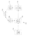
図1を参照して、たとえばインターネット100といった通信ネットワークは、複数の相互接続された通信ネットワークを備える。したがって、第1のホームルータ102は、第1のインターネットサービスプロバイダ(ISP)(図示せず)を介して、ホームサブネット及びインターネット100の一部を構成するホームリンク104をインターネット100の残りの部分に接続する。ホームリンク104は、第1のコンピューティング装置に接続されている。この第1のコンピューティング装置は、たとえば第1のパーソナルコンピュータ(PC)であり、ホームノード(Home Node)105を構成する。このホームノード105は、ホームエージェント106を構成するネットワーク管理ソフトウェアを実行する。ホームノード105は、PCである必要はなく、ホームリンク104の別のルータ等、必要なデータグラム(necessary datagram)の転送能力及びトンネリング能力(tunneling capabilities)を有する他の任意の適切なコンピューティングデバイスとすることができることが十分理解されるはずである。初期状態では、ホームリンク104は、移動ノード108にも接続されている。この移動ノード108は、たとえば、ラップトップコンピュータ等の移動コンピューティングデバイスである。
Referring to FIG. 1, a communication network such as the
同様に、第2の外部ルータ(a second, foreign, router)110は、第2のISP(図示せず)を介して、外部サブネット(foreign subnet)及びインターネット100の一部を構成する外部リンク112をインターネット100の残りの部分に接続する。また、外部リンク112は、移動ノード108が外部サブネットへ移動した場合、移動ノード108にも接続することができる。
Similarly, a second foreign router (a second, router) 110 is connected via a second ISP (not shown) to an
第3のルータ114は、第3のISP(図示せず)を介して、対応するサブネットを構成し且つインターネット100の一部を構成する対応リンク116をインターネット100の残りの部分に接続する。この対応リンク116は、対応ノード118に接続されている。対応ノード118は、たとえば、第2のPC等の第2のコンピューティング装置である。対応ノード118は、移動ノード108と通信する必要があるものである。
The
図2を参照して、ホームノード105は、複数のラインカード200を備える。これらのラインカード200の機能は、ハードウェア及びファームウェアの組み合わせ201によって提供される。各ラインカード200は、ネットワークノードからパケットを受信するための入力202、及び、他のネットワークノードへパケットを送信するための出力204を有する。ラインカード200は中央処理資源に接続されている。この中央処理資源は、第1のカーネル206を有し、使用されているプロトコルに従って必要な処理を実行し、必要に応じてデータグラムを転送又は削除(廃棄)する。第1のカーネル206は、この例では、Linuxカーネルである。第1のカーネル206は、デバイスドライバからデータグラムを受信するネットワークスタックソフトウェア(network stack software)であるデバイス受信機能ユニット210に接続された入力ドライバユニット208をサポートする。デバイス受信機能ユニット210は、入力212を介して、ホームエージェント機能ユニット214と通信することができる。このホームエージェント機能ユニット214は、この例では、第1のカーネル206によってサポートされるプロトコルスタックの標準的なIPv6機能を変更するコードフラグメント(code fragments)によって提供される。ホームエージェント機能ユニット214の入力212は、IPv6受信機能ユニット216に接続されている。このIPv6受信機能ユニット216は、IPv6転送機能ユニット218及びIPv6入力機能ユニット220に接続されている。この例では、IPv6入力機能ユニット220は、高位プロトコルレイヤ機能(図示せず)に接続されている。この高位プロトコルレイヤ機能のオペレーションは、当該技術分野において既知であり、したがって、本明細書ではこれ以上説明しないことにする。
Referring to FIG. 2,
IPv6転送機能ユニット218は、IPv6出力機能ユニット222に接続されている。また、IPv6送信機能ユニット224も、IPv6出力機能ユニット222に接続されている。この例では、高位プロトコルレイヤ機能(図示せず)も、IPv6送信機能ユニット224に接続されている。この高位プロトコルレイヤ機能のオペレーションは、当該技術分野において既知であり、したがって、本明細書ではこれ以上説明しないことにする。また、IPv6出力機能ユニット222も、出力226を介して、ホームエージェント機能ユニット214と通信することができる。ホームエージェント機能ユニット214の出力226は、デバイス送信機能ユニット228に接続されている。このデバイス送信機能ユニット228は、出力ドライバユニット230に接続されている。この出力ドライバユニット230は、ラインカード200に接続されている。
The IPv6
ハンドオーバ機構に関するあらゆる動作パラメータ、又は、ハンドオーバ機構の結果として必要な若しくは望ましいあらゆる動作パラメータの測定をサポートするために、カーネル206は、モバイルIPv6トレース機能ユニット232をサポートする。このトレース機能ユニット232は、デバイス受信機能ユニット210及びIPv6受信機能ユニット216、並びに、IPv6出力機能ユニット222及びデバイス送信機能ユニット228と通信することができる。
In order to support the measurement of any operational parameters related to the handover mechanism, or any operational parameters necessary or desirable as a result of the handover mechanism, the
図3に移って、移動ノード108は、複数のラインカード300を備える。これらのラインカード300の機能は、ハードウェア及びファームウェアの組み合わせ302によって提供される。この例では、複数のラインカード300は、単一のラインカードとなっている。ラインカード300は、ネットワークノードからパケットを受信するための入力304、及び、他のネットワークノードへパケットを送信するための出力306を有する。ラインカード300は中央処理資源に接続されている。この中央処理資源は、第2のカーネル308を有し、使用されているプロトコルに従って必要な処理を実行し、必要に応じてデータグラムを転送又は削除(廃棄)する。第2のカーネル308は、この例では、Linuxカーネルである。第2のカーネル308は、デバイスドライバからデータグラムを受信するネットワークスタックソフトウェアであるデバイス受信機能ユニット312に接続された入力ドライバユニット310をサポートする。デバイス受信機能ユニット312は、入力314を介して、移動ノード機能ユニット316と通信することができる。この移動ノード機能ユニット316は、この例では、第2のカーネル308によってサポートされるプロトコルスタックの標準的なIPv6機能を変更するコードフラグメントによって提供される。移動ノード機能ユニット316の入力314は、IPv6受信機能ユニット318に接続されている。このIPv6受信機能ユニット318は、IPv6入力機能ユニット320に接続されている。この例では、IPv6入力機能ユニット320は、高位プロトコルレイヤ機能(図示せず)に接続されている。この高位プロトコルレイヤ機能のオペレーションは、当該技術分野において既知であり、したがって、本明細書ではこれ以上説明しないことにする。
Moving to FIG. 3, the
また、移動ノード機能ユニット316は、IPv6出力機能ユニット324に接続されたIPv6送信機能ユニット322も備える。この例では、高位プロトコルレイヤ機能(図示せず)が、IPv6送信機能ユニット322に接続されている。この高位プロトコルレイヤ機能のオペレーションは、当該技術分野において既知であり、したがって、本明細書ではこれ以上説明しないことにする。IPv6出力機能ユニット324は、移動ノード機能ユニット316の出力326に接続されている。この移動ノード機能ユニット316の出力326は、デバイス送信機能ユニット328に接続されている。このデバイス送信機能ユニット328は、出力ドライバユニット330に接続されている。この出力ドライバユニット330は、ラインカード300に接続されている。
The mobile node
動作パラメータの測定をサポートするために、第2のカーネル308は、モバイルIPv6トレース機能ユニット332をサポートする。このトレース機能ユニット332は、デバイス受信機能ユニット312及びIPv6受信機能ユニット318、並びに、IPv6出力機能ユニット324及びデバイス送信機能ユニット328と通信することができる。
In order to support the measurement of operating parameters, the
動作中(図1)、移動ノード108は、最初、ホームリンク104に所属している。或る時点において、移動ノード108をホームリンク104から接続解除することが必要となり、移動ノード108を外部リンク112に所属させることが必要となる。それによって、移動ノード108は、ホームサブネットから外部サブネットへ移動する。
In operation (FIG. 1), the
この時が来ると、移動ノード108をホームサブネットから外部サブネットへ移動させるために、モバイルIPv6プロトコルによって提供されたハンドオーバ機構を使用することが必要である。サブネット間のすべてのハンドオーバが成功するとは限らず、したがって、ハンドオーバ機構の1つ又は複数のステージに関する診断に有用な情報を取得するために、ハンドオーバ機構を監視することが必要である。この点で、RFC2460(www.ietf.org/rfc/rfc2460.txt)で説明されているような、たとえばいわゆる宛先オプションヘッダといったIPv6拡張ヘッダが使用される。このIPv6拡張ヘッダによって、パケットのメインヘッダとペイロードとの間に追加情報を含めることが可能になる。しかしながら、測定される動作パラメータが他のプロトコルの拡張可能スキーマの使用を必要とする場合には、IP以外のプロトコルに関して他の既知の拡張可能スキーマを使用できることが十分理解できるはずである。
When this time comes, it is necessary to use the handover mechanism provided by the Mobile IPv6 protocol to move the
このような拡張ヘッダの使用によって、図2及び図3に関して上述した構造をサポートするために、既存のホームエージェント及び/又は移動ノードで使用される既存のIPv6プロトコルスタックに変更及び拡張が必要とされる。この例では、Unix環境が、動的にロード可能なカーネルモジュール、すなわち、移動IPv6トレース機能ユニット232及び移動IPv6トレース機能ユニット332と共に使用される。これらのモジュールは、適切に配置されたカーネル「フック」を介してカーネルプロトコルスタックの各ポイントとインターフェースする。これらのカーネル「フック」は、カーネルプロトコルスタックに事前にコンパイルされている。代替的に、これらの変更及び拡張は、カーネルプロトコルスタックのソースコードにパッチを適用し、次いで、そのカーネルを再コンパイルすることによっても達成することができる。この点で、パケットの拡張ヘッダへの測定データの組み込みのサポートを提供するために、第1のカーネル206及び第2のカーネル308は、欧州特許公開第EP−A−1 401 147号に従って適合される。しかしながら、Unixベースのカーネルを使用できるが、Microsoft Windows(商標)のさまざまなバージョン等、他のカーネルに利用可能な、動的にリンク可能なライブラリを使用して、本明細書で説明したものと同じ機能を達成することが可能である。
The use of such extension headers requires changes and extensions to the existing IPv6 protocol stack used by existing home agents and / or mobile nodes to support the structure described above with respect to FIGS. The In this example, the Unix environment is used with dynamically loadable kernel modules, ie, the Mobile IPv6 Trace
図4に移って、移動ノード108が外部リンク112に所属すると、移動ノード108は、移動検出アルゴリズムと、外部ルータ(foreign router)110から受信されたルータ広告メッセージ400の受信とによって、外部サブネットに移動したことに暗黙的に気付き、モバイルIPv6ハンドオーバ、すなわちハンドオーバ機構の実行、の起点となる。ルータ広告メッセージ400は、移動ノード108がホームリンク104に所属していた時に前に受信していたIPv6アドレスプリフィックス(address prefix:接頭アドレス)とは異なるIPv6アドレスプリフィックスを含む。その結果、移動ノード108のトレース機能ユニット332は、この異なるIPv6アドレスプリフィックスを含むルータ広告メッセージ400を認識し(ステップ402)、次に、ハンドオーバ識別値(HIV(Handover Identification Value))を計算する。このHIVは、たとえば16ビットといったカウンタが、移動ノード108に関する一意の識別子及び所属指示子の新しいポイントと結合されたものから成る。この移動ノード108に関する一意の識別子は、たとえば、64ビット拡張一意識別子(EUI−64(Extended Unique Identifiers-64-bit))アドレス等、移動ノード108のインターフェースアドレスである。所属指示子の新しいポイントは、たとえば、上記異なるIPv6アドレスプリフィックスである。HIVは、現在のIPv6ハンドオーバに関して記録される今後のすべての測定データに関連付けられる。また、トレース機能ユニット332は、ルータ広告メッセージ400の到着時刻であるタイムスタンプも計算し、このタイムスタンプと、HIV値と、メッセージタイプ識別子とを含む第1のデータ構造体を形成する。この例では、第1のデータ構造体は、最小限のものであり、タイムスタンプ及びHIVを含む。
Turning to FIG. 4, when the
第1のデータ構造体は、現在のモバイルIPv6ハンドオーバに関するデータ構造体の一時ストアにおける第1のエントリを成す。この一時ストアは、モバイルIPv6ハンドオーバが移動ノード108に関して進行中であることを示す新しい「アクティブ」ストア(store:記憶)ステータスを取得する。ハンドオーバがもはやアクティブでない場合、たとえば、ハンドオーバが成功して完了した後、又は、ハンドオーバが、超えることができない、ハンドオーバ機構のステージに到達した後は、このような「非アクティブ」ストアに寿命を割り当てることができる。この寿命の時間の間、非アクティブストア(non-active store:非アクディブ記憶装置)の内容は、集中管理処理へ転送することができる。寿命が満了するか、又は、外部の管理エージェント(図示せず)により非アクティブストアの内容が収集されると、非アクティブストアは、メモリから消去される。代替的に、メモリ資源が、アクティブストアに追加されたデータ構造体用に使い果たされた時、非アクティブデータストアは、トレース機能ユニット332によって消去され、且つ/又は上書きされる。
The first data structure forms a first entry in the temporary store of data structures for the current mobile IPv6 handover. This temporary store gets a new “active” store status indicating that a Mobile IPv6 handover is in progress for the
その後、オプションではあるが、移動ノード108は、別のサブネットへの移動が発生したかどうかを確かめるために、ハンドオーバ機構の一部として、近隣到達不能検出(NUD(Neighbour Unreachability Detection))ルータ要請メッセージ406を送信する(ステップ404)。このイベント、すなわち、NUDルータ要請メッセージ406の送信、を記録するために、トレース機能ユニット332は、少なくともNUDルータ要請メッセージ406の送信時刻を含む第2のデータ構造体を形成し、この第2のデータ構造体をアクティブストアに追加する。外部ルータ110は、NUDルータ要請メッセージ406に応答して、NUDルータ広告メッセージ408を外部サブネット上に送信する。このNUDルータ広告メッセージ408の受信は、移動ノード108によって検出される。その後、トレース機能ユニット332は、少なくともNUDルータ広告メッセージ408の受信時刻を有する第3のデータ構造体を形成し(ステップ410)、この第3のデータ構造体をアクティブストアに追加する。
Thereafter, although optional, the
その後、再びオプションとして、移動ノード108は、重複アドレス検出(DAD(Duplicate Address Detection))メッセージ414を外部(新しい)サブネット上に送信する(ステップ412)。次に、トレース機能ユニット332は、少なくともDADメッセージ414の送信時刻と、HIV値と、メッセージタイプ識別子とを含む第4のデータ構造体を形成する。この第4のデータ構造体は、アクティブストアに追加される。
Thereafter, again as an option, the
次に、移動ノード108は、モバイルIPv6ハンドオーバ機構による移動ノード108用の気付アドレスを登録するために、バインド更新(BU(Binding Update))メッセージ418をホームエージェント106へ送信する(ステップ416)準備を行う。トレース機能ユニット332は、BUメッセージ418の送信であるイベントを記録するために、少なくともHIV値と、メッセージタイプ識別子と、BUメッセージの送信時刻のタイムスタンプとを含む第5のデータ構造体を形成する。次に、トレース機能ユニット332は、この第5のデータ構造体をアクティブストアに追加する。トレース機能ユニット332は、BUメッセージ418の送信(ステップ416)前に、BUメッセージ418のIPv6宛先オプションヘッダの宛先オプションの形のデータとして収集された第1のデータ構造体、第2のデータ構造体、第3のデータ構造体、第4のデータ構造体、及び第5のデータ構造体を含む。次に、第1のデータ構造体、第2のデータ構造体、第3のデータ構造体、第4のデータ構造体、及び第5のデータ構造体を組み込んだBUメッセージ418は、ホームエージェント106によって受信される(ステップ420)。
Next, the
ホームエージェント106は、BUメッセージ418を受信すると、モバイルIPv6ハンドオーバ機構の一部として、ホームエージェント106のバインドキャッシュ(binding cache)(図示せず)に新しいエントリを作成して、移動ノード108のホームアドレスを気付アドレスに関連付ける。ホームエージェント106のトレース機能ユニット232は、受信したBUメッセージ418の宛先オプションヘッダからデータ構造体を収集する。これは、移動ノード108に関して進行中のモバイルIPv6ハンドオーバに関するホームエージェント106のデータ構造体の一時ストアにおける最初の5エントリを形成する。このモバイルIPv6ハンドオーバは、HIVによって特定される。ホームエージェント106のこの一時ストアは、移動ノード108の「アクティブ」ストアステータスも取得する。これに加えて、ホームエージェント106のトレース機能ユニット232は、少なくともBUメッセージ418の到着時刻のタイムスタンプと、HIV値と、メッセージタイプ識別子とを含む第6のデータ構造体を形成する。次に、この第6のデータ構造体は、ホームエージェント106のアクティブデータストアに記憶される。
Upon receipt of the
次に、ホームエージェント106は、重複アドレス検出(DAD)メッセージ424をホームサブネット上に送信し(ステップ422)、ホームエージェント106のトレース機能ユニット232は、少なくともDADパケットの送信時刻と、HIV値と、メッセージタイプ識別子とを有する第7のデータ構造体を形成する。次に、ホームエージェント106のトレース機能ユニット232は、この第7のデータ構造体をホームエージェント106のアクティブストアに追加する。その後、ホームエージェント106は、プロキシ近隣広告(PNA(Proxy Neighbour Advertisement))メッセージ430をホームサブネットへ送信し(ステップ428)、トレース機能ユニット232は、少なくともPNAメッセージ430の送信時刻と、HIV値と、メッセージタイプ識別子とを含む第8のデータ構造体を形成する。次に、この第8のデータ構造体は、ホームエージェント106のアクティブストアに追加される。
Next, the
その後、ホームエージェントは、有効なバインド関連付けが形成されたことを移動ノード108に信号で伝えるために、バインド肯定応答メッセージ434を移動ノード108へ送信する(ステップ432)準備を行う。このイベントを記録するために、ホームエージェント106のトレース機能ユニット232は、少なくともバインド肯定応答メッセージ434の送信時刻のタイムスタンプと、HIV値と、メッセージタイプ識別子とを含む第9のデータ構造体を形成し、この第9のデータ構造体をホームエージェント106のアクティブストアに追加する。これに加えて、バインド肯定応答メッセージ434の送信前に、ホームエージェント106のトレース機能ユニット232は、バインド肯定応答メッセージ434のIPv6宛先オプションヘッダの宛先オプションの形のデータとして収集された第6のデータ構造体、第7のデータ構造体、第8のデータ構造体、及び第9のデータ構造体を含む。
The home agent then prepares to send a
次に、バインド肯定応答メッセージ434は、移動ノード108によって受信され(ステップ436)、移動ノード108のトレース機能ユニット332は、バインド肯定応答メッセージ434の宛先オプションヘッダから第6のデータ構造体、第7のデータ構造体、第8のデータ構造体、及び第9のデータ構造体を収集する。これは、移動ノード108のアクティブストアにおける次の4つのエントリを形成する。これに加えて、移動ノード108のトレース機能ユニット332は、少なくともバインド肯定応答メッセージの到着時刻のタイムスタンプと、HIV値と、メッセージタイプ識別子とを含む第10のデータ構造体を形成する。次に、この第10のデータ構造体は、移動ノード108のアクティブストアに追加される。
The
移動ノード108のアクティブストアに第10のデータ構造体を記録した後、移動ノード108のトレース機能ユニット332は、ホームエージェント106への送信(ステップ440)の準備がされている次の利用可能なパケット438、たとえば、BUメッセージ又はバインドリフレッシュメッセージ(Binding Refresh messages)、を使用して、当該次の利用可能なパケットを送信する前に、当該次の利用可能なパケットのIPv6宛先オプションヘッダの宛先オプションの形で収集された第10のデータ構造体を運ぶ。
After recording the tenth data structure in the mobile node's 108 active store, the
ホームエージェント106は、次に利用可能なパケットを受信すると(ステップ442)、宛先オプションヘッダから第10のデータ構造体を収集する。この第10のデータ構造体は、ホームエージェント106のアクティブストアの最後のエントリを形成する。
When
別の実施の形態では、移動ノード108は、外部サブネットからホームサブネットへ再び移動する。すなわち、ホームサブネットに戻る。ホームサブネットへ移動して戻る場合、ハンドオーバ機構は、異なる1組のメッセージトランザクションを使用して、ハンドオーバを実行する。一方、測定データ共有処理は、すでに上述したものと全く同様である。しかし、それでも、十分に異なるので説明に値する。
In another embodiment, the
図5を参照して、移動ノード108の外部サブネットからホームサブネットへの再移動に関して、上記ですでに説明した監視処理と同じ目的が追求される。すなわち、ホームエージェント106及び移動ノード108の双方における各モバイルIPv6ハンドオーバに関連したメッセージトランザクションダイアログに関する最新の情報を保持することが追求される。
Referring to FIG. 5, the same purpose as the monitoring process already described above is pursued regarding the re-movement of the
移動ノード108がホームリンク104に再び所属すると、移動ノード108は、移動検出アルゴリズムと、ホームルータ102から受信された1つ又は複数のルータ広告メッセージ500の受信とによって、ホームサブネットに再び移動したことに暗黙的に気付き、別のモバイルIPv6ハンドオーバの実行の起点となる。ルータ広告メッセージ500は、移動ノード108が外部リンク112に所属していた時に前に受信していたIPv6アドレスプリフィックスとは異なるIPv6アドレスプリフィックスを含む。その結果、移動ノード108のトレース機能ユニット332は、この異なるIPv6アドレスプリフィックスを含むルータ広告メッセージ500を認識し(ステップ502)、次に、すでに上述した方法で新しいハンドオーバ識別値(HIV)を計算する。また、すでに述べたように、トレース機能ユニット332は、ルータ広告メッセージ500の到着時刻のタイムスタンプも計算し、このタイムスタンプと、HIV値と、メッセージタイプ識別子とを含む第1のデータ構造体を形成する。この例でも、第1のデータ構造体は、最小限のものであり、単にタイムスタンプ、HIV、及びIPv6アドレスプリフィックスを含む。次に、第1のデータ構造体は、移動ノード108に関する新たな「アクティブ」ストアの最初のエントリを成す。
When the
その後、移動ノード108は、ホームエージェントのリンクレイヤアドレスを発見するために、ハンドオーバ機構の一部として、ホームエージェントの要請ノードマルチキャストアドレスへ第1の近隣要請メッセージ506を送信する(ステップ504)準備を行う。次に、移動ノード108のトレース機能ユニット332は、第1の近隣要請メッセージ506の送信であるイベントを記録するために、第1の近隣要請メッセージ506の送信時刻のタイムスタンプと、HIV値と、メッセージタイプ識別子とを含む第2のデータ構造体を形成する。次に、トレース機能ユニット332は、この第2のデータ構造体を移動ノード108のアクティブストアに追加し、第1の近隣要請メッセージ506の送信(ステップ504)前に、第1の近隣要請メッセージ506のIPv6宛先オプションヘッダの宛先オプションの形のデータとして収集された第1のデータ構造体及び第2のデータ構造体を含む。次に、第1のデータ構造体及び第2のデータ構造体を組み込んだ第1の近隣要請メッセージ506は、ホームエージェント106によって受信される(ステップ508)。
The
ホームエージェント106のトレース機能ユニット232は、第1の近隣要請メッセージ506を受信すると、受信した第1の近隣要請メッセージ506の宛先オプションヘッダから第1のデータ構造体及び第2のデータ構造体を収集する。これは、ホームエージェント106に関する新しいアクティブストアにおける最初の2つのエントリを形成する。これに加えて、ホームエージェント106のトレース機能ユニット232は、第1の近隣要請メッセージ(Neighbour Solicitation message)506の到着時刻のタイムスタンプと、HIV値と、メッセージタイプ識別子とを含む第3のデータ構造体を形成する。次に、この第3のデータ構造体は、ホームエージェント106のアクティブデータストアに記憶される。
When receiving the first
ホームルータ102は、第1の近隣要請メッセージ506に応答して、第1の近隣広告メッセージ512を送信する(ステップ510)準備を行う。この第1の近隣広告メッセージ(Neighbour Advertisement message)512の受信は、移動ノード108によって検出される。次に、ホームエージェント106のトレース機能ユニット232は、第1の近隣広告メッセージ512の送信であるイベントを記録するために、第1の近隣広告メッセージ512の送信時刻のタイムスタンプと、HIV値と、メッセージタイプ識別子とを含む第4のデータ構造体を形成する。次に、ホームエージェント106のトレース機能ユニット232は、この第4のデータ構造体をアクティブストアに追加し、第1の近隣広告メッセージ512を送信する(ステップ510)前に、第1の近隣広告メッセージ512のIPv6宛先オプションヘッダの宛先オプションの形のデータとして収集された第3のデータ構造体及び第4のデータ構造体を含む。次に、第3のデータ構造体及び第4のデータ構造体を組み込んだ第1の近隣広告メッセージ512は、移動ノード108によって受信される(ステップ514)。
The
移動ノード108のトレース機能ユニット332は、第1の近隣広告メッセージ512を受信すると、受信した第1の近隣広告メッセージ512の宛先オプションヘッダから第3のデータ構造体及び第4のデータ構造体を収集する。これは、移動ノード108のアクティブストアにおける第3のエントリ及び第4のエントリを形成する。これに加えて、移動ノード108のトレース機能ユニット332は、第1の近隣広告メッセージ512の到着時刻のタイムスタンプと、HIV値と、メッセージタイプ識別子とを含む第5のデータ構造体を形成する。次に、この第5のデータ構造体は、移動ノード108のアクティブデータストアに記憶される。
When the
その後、移動ノード108は、移動ノード108が戻ったことをホームリンクに示すために、モバイルIPv6ハンドオーバ機構に従って、特別なBUメッセージ518をホームエージェント106へ送信する(ステップ516)準備を行う。トレース機能ユニット332は、このBUメッセージ518の送信であるイベントを記録するために、BUメッセージ518の送信時刻のタイムスタンプと、HIV値と、メッセージタイプ識別子とを含む第6のデータ構造体を形成する。次に、移動ノード108のトレース機能ユニット332は、この第6のデータ構造体を移動ノード108のアクティブストアに追加し、BUメッセージ518の送信(ステップ516)前に、BUメッセージ518のIPv6宛先オプションヘッダの宛先オプションの形のデータとして収集された第5のデータ構造体及び第6のデータ構造体を含む。次に、第5のデータ構造体及び第6のデータ構造体を組み込んだBUメッセージ518は、ホームエージェント106によって受信される(ステップ520)。
Thereafter, the
ホームエージェント106のトレース機能ユニット232は、BUメッセージ518を受信すると、受信したBUメッセージ518の宛先オプションヘッダからデータ構造体を収集する。これは、ホームエージェント106のアクティブストアにおける第5のエントリ及び第6のエントリを形成する。これに加えて、ホームエージェント106のトレース機能ユニット232は、BUメッセージ518の到着時刻のタイムスタンプと、HIV値と、メッセージタイプ識別子とを含む第7のデータ構造体を形成する。次に、この第7のデータ構造体は、アクティブデータストアに記憶される。
Upon receiving the
その後、ホームエージェント106は、あらゆるバインド肯定応答メッセージを送信する前に、移動ノード108がホームリンクに存在することを保証するために、ハンドオーバ機構の一部として、第2の近隣要請メッセージ524を送信する(ステップ522)準備を行う。次に、ホームエージェント106のトレース機能ユニット232は、第2の近隣要請メッセージ524の送信であるイベントを記録するために、第2の近隣要請メッセージ524の送信時刻のタイムスタンプと、HIV値と、メッセージタイプ識別子とを含む第8のデータ構造体を形成する。次に、トレース機能ユニット232は、この第8のデータ構造体をホームエージェント106のアクティブストアに追加し、第2の近隣要請メッセージ524の送信(ステップ522)前に、第2の近隣要請メッセージ524のIPv6宛先オプションヘッダの宛先オプションの形のデータとして収集された第7のデータ構造体及び第8のデータ構造体を含む。次に、第7のデータ構造体及び第8のデータ構造体を組み込んだ第2の近隣要請メッセージ524は、移動ノード108によって受信される(ステップ528)。
The
移動ノード108のトレース機能ユニット332は、近隣要請メッセージ524を受信すると、受信した第2の近隣要請メッセージ524の宛先オプションヘッダからデータ構造体を収集する。これは、移動ノード108のアクティブストアにおける第7のエントリ及び第8のエントリを形成する。これに加えて、移動ノード108のトレース機能ユニット332は、第2の近隣要請メッセージ524の到着時刻のタイムスタンプと、HIV値と、メッセージタイプ識別子とを含む第9のデータ構造体を形成する。次に、この第9のデータ構造体は、移動ノード108のアクティブデータストアに記憶される。
Upon receiving the
移動ノード108は、第2の近隣要請メッセージ524に応答して、第2の近隣広告メッセージ532を送信する(ステップ530)準備を行う。次に、移動ノード108のトレース機能ユニット332は、第2の近隣広告メッセージ532の送信であるイベントを記録するために、第2の近隣広告メッセージ532の送信時刻のタイムスタンプと、HIV値と、メッセージタイプ識別子とを含む第10のデータ構造体を形成する。次に、トレース機能ユニット332は、この第10のデータ構造体を移動ノード108のアクティブストアに追加し、第2の近隣広告メッセージ532を送信する(ステップ530)前に、第2の近隣広告メッセージ532のIPv6宛先オプションヘッダの宛先オプションの形のデータとして収集された第9のデータ構造体及び第10のデータ構造体を含む。次に、第9のデータ構造体及び第10のデータ構造体を組み込んだ第2の近隣広告メッセージ532は、ホームエージェント106によって受信される(ステップ534)。
In response to the second
ホームエージェント106のトレース機能ユニット232は、第2の近隣広告メッセージ532を受信すると、受信した第2の近隣広告メッセージ532の宛先オプションヘッダからデータ構造体を収集する。これは、ホームエージェント106のアクティブストアにおける第9のエントリ及び第10のエントリを形成する。これに加えて、ホームエージェント106のトレース機能ユニット232は、第2の近隣広告メッセージ532の到着時刻のタイムスタンプと、HIV値と、メッセージタイプ識別子とを含む第11のデータ構造体を形成する。次に、この第11のデータ構造体は、アクティブデータストアに記憶される。
When the
次に、ホームエージェント106は、再びホームエージェント106との有効なバインド関連付けが形成されたことを移動ノード108に信号で伝えるために、バインド肯定応答メッセージ538を移動ノード108へ送信する(ステップ536)準備を行う。バインド関連付けが形成された結果、トンネル及び逆トンネル(本明細書で後述)が確立される。このイベントを記録するために、ホームエージェント106のトレース機能ユニット232は、バインド肯定応答メッセージ538の送信時刻のタイムスタンプと、HIV値と、メッセージタイプ識別子とを含む第12のデータ構造体を形成し、この第12のデータ構造体をホームエージェント106に関連したアクティブストアに追加する。これに加えて、バインド肯定応答メッセージ538の送信前に、ホームエージェント106のトレース機能ユニット232は、バインド肯定応答メッセージ538のIPv6宛先オプションヘッダの宛先オプションの形のデータとして収集された第11のデータ構造体及び第12のデータ構造体を含む。
The
次に、バインド肯定応答メッセージ538は、移動ノード108によって受信され(ステップ540)、移動ノード108のトレース機能ユニット332は、バインド肯定応答メッセージ538の宛先オプションヘッダから第11のデータ構造体及び第12のデータ構造体を収集する。これは、移動ノード108のアクティブストアにおける次の2つのエントリを形成する。これに加えて、移動ノード108のトレース機能ユニット332は、バインド肯定応答メッセージの到着時刻のタイムスタンプと、HIV値と、メッセージタイプ識別子とを含む第13のデータ構造体を形成する。次に、この第13のデータ構造体は、移動ノード108のアクティブストアに追加される。
The
バインド肯定応答メッセージ538に応答して、移動ノード108は、ホームリンク104のノードが、移動ノード108のリンクローカルアドレスとリンクレイヤ媒体アクセス制御(MAC)アドレスとの間の関連付けを行うことができるように、ハンドオーバ機構の一部として、第3の近隣広告メッセージ544をホームリンク104のすべてのノードへ送信する(ステップ542)。次に、移動ノード108のトレース機能ユニット332は、第3の近隣広告メッセージ544の送信であるイベントを記録するために、第3の近隣広告メッセージ544の送信時刻のタイムスタンプと、HIV値と、メッセージタイプ識別子とを含む第14のデータ構造体を形成する。次に、トレース機能ユニット332は、この第14のデータ構造体を移動ノード108のアクティブストアに追加する。第3の近隣広告メッセージ544の送信(ステップ542)前に、トレース機能ユニット332は、第3の近隣広告メッセージ544のIPv6宛先オプションヘッダの宛先オプションの形のデータとして収集された第13のデータ構造体及び第14のデータ構造体を含む。次に、第13のデータ構造体及び第14のデータ構造体を組み込んだ第3の近隣広告メッセージ544は、ホームエージェント106によって受信される。
In response to the
ホームエージェント106は、マルチキャスト近隣広告メッセージ544のコピーを受信するので、ホームエージェント106のトレース機能ユニット232は、受信した第3の近隣広告メッセージ544の宛先オプションヘッダからデータ構造体を収集する。これは、ホームエージェント106のアクティブストアにおける第13のエントリ及び第14のエントリを形成する。これに加えて、ホームエージェント106のトレース機能ユニット232は、第3の近隣広告メッセージ544の到着時刻のタイムスタンプと、HIV値と、メッセージタイプ識別子とを含む第15のデータ構造体を形成する。次に、この第11のデータ構造体は、アクティブデータストアに記憶される。
Since the
次に、移動ノード108は、ホームリンク104のノードが、移動ノード108のホームアドレスと移動ノード108のリンクレイヤ(MAC)アドレスとの間の関連付けを行うことができるように、ハンドオーバ機構の一部として、第4の近隣広告メッセージ548をホームリンク104のすべてのノードへ送信する(ステップ546)準備を行う。次に、移動ノード108のトレース機能ユニット332は、第4の近隣広告メッセージ548の送信であるイベントを記録するために、第4の近隣広告メッセージ548の送信時刻のタイムスタンプと、HIV値と、メッセージタイプ識別子とを含む第16のデータ構造体を形成する。次に、トレース機能ユニット332は、この第16のデータ構造体をアクティブストアに追加し、第4の近隣広告メッセージ548の送信(ステップ546)前に、トレース機能ユニット332は、第4の近隣広告メッセージ548のIPv6宛先オプションヘッダの宛先オプションの形のデータとして収集された第16のデータ構造体を含む。第16のデータ構造体を組み込んだ第4の近隣広告メッセージ548は、ホームエージェント106によって受信される。
Next, the
ホームエージェント106は、マルチキャスト近隣広告メッセージ548のコピーを受信するので、ホームエージェント106のトレース機能ユニット232は、受信した第4の近隣広告メッセージ548の宛先オプションヘッダからデータ構造体を収集する。これは、ホームエージェント106のアクティブストアにおける第16のエントリを形成する。これに加えて、ホームエージェント106のトレース機能ユニット232は、第4の近隣広告メッセージ548の到着時刻のタイムスタンプと、HIV値と、メッセージタイプ識別子とを含む第17のデータ構造体を形成する。次に、この第17のデータ構造体は、アクティブデータストアに記憶される。ホームエージェント106から移動ノード108へ第15のデータ構造体及び/又は第17のデータ構造体を通信するために、例外的なデータグラムを、ホームエージェント106から移動ノード108へ第15のデータ構造体及び/又は第17のデータ構造体を通信するための伝達手段として使用することができる。この例外的なデータグラムは、その名前が示唆するように、これまではホームエージェント106から移動ノード108へ通信されなかった第15のデータ構造体及び/又は第17のデータ構造体を通信する目的で例外的に形成される。この例外的なパケットの宛先オプションヘッダは、第15のデータ構造体及び第17のデータ構造体の一方又は双方を収容するのに使用される。これに代えて、又は、これに加えて、ハンドオーバ処理の完了の後にホームエージェント106から移動ノード108へ送信されるユーザ(非シグナリング)データグラムの宛先オプションヘッダを、ホームエージェント106から移動ノード108へ第15のデータ構造体及び/又は第17のデータ構造体を通信するための伝達手段として使用することもできる。
Since the
別の実施の形態では、モバイルIPv6のハンドオーバ機構は、外部サブネットから別の外部サブネット(図示せず)への移動ノード108の移動を行うのに使用される。このような例では、ハンドオーバ機構の監視技法の実行は、ホームサブネットから外部サブネットへの移動ノード108の移動に関してすでに上述したものと同様であり、したがって、説明を簡潔にするために、本明細書ではこれ以上説明しないことにする。
In another embodiment, the Mobile IPv6 handover mechanism is used to move the
別の例では、対応ノード118が移動ノード108からバインド更新メッセージを受け取ることを可能にするために、モバイルIPv6経路最適化が実行される。移動ノード108は、バインド更新メッセージを使用して、移動ノード108の現在位置、すなわち、移動ノード108の現在の気付アドレス、を対応ノード118に知らせる。次に、対応ノードは、その(新しい)気付アドレスを知り、ホームエージェント106を介するのではなく移動ノード108へパケットを直接送信する。移動ノード108が、確かに、報告されたホームアドレスだけでなく、(主張された)気付アドレスでもアドレス指定可能であるといういくつかの保証を対応ノード118に提供するために、対応ノード118が移動ノード108から「バインド更新(binding update)」を受け取ることができるようになる前に、対応ノード118及び移動ノード108の双方は、「往復経路確認(return routability)」処理として知られているダイアログに入る。
In another example, mobile IPv6 route optimization is performed to allow the
上記ですでに説明した監視処理は、往復経路確認処理の1つ又は複数のイベントの実行を監視するために、往復経路確認処理について使用することができる。この点で、図6を参照して、往復経路確認処理は、移動ノード108がホームエージェント106を介してホームテスト開始メッセージ(Home Test Init message)602を送信する(ステップ600)ことによって開始される。したがって、ホームテスト開始メッセージ602は、最初に、逆トンネル(reverse tunnel)604を介してホームエージェント106へ送信される(ステップ600)。この逆トンネル604は、移動ノード108とホームエージェント106との間のバインド関連付けによってすでに確立されている。次いで、ホームテスト開始メッセージ602は、ホームエージェント106によって対応ノード118へ転送される(ステップ606)。
The monitoring process already described above can be used for a round trip confirmation process to monitor the execution of one or more events of the round trip confirmation process. In this regard, referring to FIG. 6, the round trip route confirmation process is started when the
一方、移動ノード108がホームテスト開始メッセージ602を送信する(ステップ600)前に、移動ノード108のトレース機能ユニット332は、ホームテスト開始メッセージ602の送信であるイベントを記録するために、ホームテスト開始メッセージ602の送信時刻と、新しいHIV値と、メッセージタイプ識別子とを含む第1のデータ構造体を形成する。次に、この第1のデータ構造体は、現在の往復経路確認処理に関するデータ構造体のさらに新しいアクティブストアに記憶される。ホームエージェント106のトレース機能ユニット232は、ホームテスト開始メッセージ602の送信(ステップ600)前に、ホームテスト開始メッセージ602のIPv6宛先オプションヘッダの宛先オプションの形のデータとして収集された第1のデータ構造体を含む。
On the other hand, before the
ホームエージェント106のトレース機能ユニット232は、トンネリングされたホームテスト開始メッセージ602を受信すると(ステップ608)、ホームテスト開始メッセージ602の宛先オプションヘッダから第1のデータ構造体を収集し、ホームエージェント106に関してではあるが、現在の往復経路確認処理に関するさらに新しいアクティブデータストアに第1のエントリとして第1のデータ構造体を記憶する。次に、ホームエージェント106のトレース機能ユニット232は、ホームテスト開始メッセージ602の受信時刻と、HIV値と、メッセージタイプ識別子とを含む第2のデータ構造体を形成することによって、ホームテスト開始メッセージ602の受信を記録し、次いで、この第2のデータ構造体をホームエージェント106のアクティブストアに記憶する。次に、ホームエージェント106のトレース機能ユニット232は、ホームテスト開始メッセージ602を対応ノード118へ転送し(ステップ606)、ホームテスト開始メッセージ602の転送時刻と、HIV値と、メッセージタイプ識別子とを含む第3のデータ構造体を形成する。次に、ホームエージェント106のトレース機能ユニット232は、この第3のデータ構造体をホームエージェント106のアクティブストアに追加する。
Upon receipt of the tunneled home test start message 602 (step 608), the
次に、移動ノード108のトレース機能ユニット332は、気付テスト開始メッセージ(Care-of Test Init message)612を対応ノード118へ送信する(ステップ610)と共に、気付テスト開始メッセージ612の送信時刻と、HIV値と、メッセージタイプ識別子とを含む第4のデータ構造体を形成する。
Next, the
対応ノード118は、気付テスト開始メッセージ612を受信すると(ステップ614)、ホームテストメッセージ618をホームエージェント106へ送信し(ステップ616)、ホームテストメッセージ618は、移動ノード108へ転送される(ステップ620)。ホームエージェント106は、ホームテストメッセージ618を受信すると(ステップ622)、ホームテストメッセージ618の受信時刻と、HIV値と、メッセージタイプ識別子とを含む第5のデータ構造体を形成する。次に、ホームエージェント106は、トンネル624を使用して、ホームテストメッセージ618を移動ノード108へ転送する(ステップ620)準備を行う。このトンネル624は、移動ノード108とホームエージェント106との間のバインド関連付けを介してすでに確立されている。このイベントを記録するために、ホームエージェント106のトレース機能ユニット232は、ホームテストメッセージ618の転送時刻のタイムスタンプと、HIV値と、メッセージタイプ識別子とを含む第6のデータ構造体を形成し、この第6のデータ構造体をホームエージェント106のアクティブストアに追加する。これに加えて、ホームテストメッセージ618の転送前に、ホームエージェント106のトレース機能ユニット232は、ホームテストメッセージ618のIPv6宛先オプションヘッダの宛先オプションの形のデータとして収集された第2のデータ構造体、第3のデータ構造体、第5のデータ構造体、及び第6のデータ構造体を含む。
Upon receiving the care-of test start message 612 (step 614), the corresponding
移動ノード108は、トンネリングされたホームテストメッセージ618を受信すると(ステップ626)、受信したホームテストメッセージ618の宛先オプションヘッダからデータ構造体を収集する。これは、移動ノード108のアクティブストアにおける第2のエントリ、第3のエントリ、第5のエントリ、及び第6のエントリを形成する。これに加えて、移動ノード108のトレース機能ユニット332は、ホームテストメッセージ618の到着時刻のタイムスタンプと、HIV値と、メッセージタイプ識別子とを含む第7のデータ構造体を形成する。次に、この第7のデータ構造体は、移動ノード108のアクティブデータストアに記憶される。
When the
その後、対応ノード118は、移動ノード108へ気付テストメッセージ630を直接送信する(ステップ628)。移動ノード108は、気付テストメッセージ630を受信すると(ステップ632)、気付テストメッセージ630の受信時刻と、HIV値と、メッセージタイプ識別子とを含む第8のデータ構造体を形成する。次に、この第8のデータ構造体は、移動ノード108のアクティブデータストアに記憶される。次に、移動ノード108は、BUメッセージ636を対応ノード118へ送信する(ステップ634)準備を行い、BUメッセージ636の送信時刻と、HIV値と、メッセージタイプ識別子とを含む第9のデータ構造体を形成することによって、BUメッセージ636の送信を記録する。この第9のデータ構造体は、移動ノード108のアクティブデータストアに記憶される。
Thereafter, the corresponding
対応ノード118は、BUメッセージ636を受信すると(ステップ638)、移動ノード108によって受信される(ステップ644)バインド肯定応答メッセージ642を送信する(ステップ640)。その後、移動ノード108は、バインド肯定応答メッセージ642を受信すると、バインド肯定応答メッセージ642の受信時刻と、HIV値と、メッセージタイプ識別子とを含む第10のデータ構造体を形成する。次に、この第10のデータ構造体は、移動ノード108のアクティブデータストアに記憶される。ハンドオーバ機構の一部としてのホームエージェント106との通信はこれ以上必要ではないので、移動ノード108からホームエージェント106へ送信される次のパケットは、第4のデータ構造体、第7のデータ構造体、第8のデータ構造体、第9のデータ構造体、及び第10のデータ構造体をホームエージェント106へ通信するのに使用することができる。代替的に、移動ノード108は、所定のタイムアウト期間の後に、空のペイロードを有するいわゆる「ダミー」メッセージをホームエージェント106へ送信することができ、第4のデータ構造体、第7のデータ構造体、第8のデータ構造体、第9のデータ構造体、及び第10のデータ構造体は、このダミーメッセージのIPv6宛先オプションヘッダの宛先オプションの形のデータとして送信される。次に、このように通信されたデータ構造体は、他のメッセージに関してすでに上述したのと同じ方法で収集することができる。
When the
ホームエージェント106及び/又は移動ノード108によって作成されたデータストアは、ホームエージェント106及び/又は移動ノード108が、それぞれ通信ネットワーク内の集中監視エンティティへ送信することができる。この集中監視エンティティは、たとえばオペレーションサポートシステム(OSS)アプリケーション(図示せず)といった集中監視処理をサポートする。したがって、OSSアプリケーションは、部分的なデータ記録、完全なデータ記録、又は局所的なデータ記録を取得することができる。移動ノード108又はホームエージェント106のいずれかから収集されたデータは部分的な記録を構成するのに対して、移動ノード108及びホームエージェント106の双方から収集されたデータは完全な記録を構成する。局所的なデータ記録は、たとえば、OSSアプリケーションが、たとえばインターネット100といった通信ネットワークの特定の無線セル(cell)又は領域に問い合わせを行い、すべての移動ノードの最新の1組の記憶された記録を送信するようにそれらすべての移動ノードに要求することによって、取得される。
The data store created by the
ハンドオーバが完了するか、又は、完了できないと、ホームエージェント106及び/又は移動ノード108から収集されたデータ記録によって、ハンドオーバ処理及び遅延をトレースすることが可能となり、障害ポイントの範囲を限定するか、又は、障害ポイントを特定することが可能となる。データストアの各エントリに対応するデータ構造体に記憶された情報量に応じて、障害の正確な原因を診断することさえも可能にすることができる。
When the handover is completed or cannot be completed, the data records collected from the
ハンドオーバ機構の1つ又は複数のステージに関する遅延を求めることについて、任意の適切な既知のクロック同期技法を使用して、ホームエージェント106及び移動ノード108の内部クロックが同期されることが十分理解されるはずである。一方、内部クロックが同期されない場合であっても、モバイルIPv6ハンドオーバの経過を監視することが依然として可能である。また、同じ位置で形成されたメッセージのタイムスタンプを比較することも可能であり、たとえば、移動ノード108で形成されたメッセージのタイムスタンプ又はホームエージェント106で形成されたメッセージのタイムスタンプを比較することが可能である。
With respect to determining the delay for one or more stages of the handover mechanism, it is well understood that the internal clocks of the
上記例は、監視機能を有する移動ノード108及びホームエージェント106との関連で説明されたが、上述した監視技法は大きな適応性を有することが十分理解されるはずである。この点で、上述した監視機能は、移動ノードのみに適用することもできるし、ホームエージェントのみに適用することもできるし、移動ノード及びホームエージェントに適用することもできるし、可能ならば、対応ノードに適用することもできる。対応ノードが上述した監視技法に参加することになる場合、対応ノードは、移動ノード108に関して上述したアーキテクチャ及び機能を共有することができる。上述した監視技法は、モバイルIPv6トレースの一例にすぎないことが十分理解されるはずであり、所与の完全なモバイルIPv6トレースを形成する一連のメッセージは、監視されているネットワークの構成に応じて異なることが十分理解されるはずである。したがって、当業者には、上述したアーキテクチャ及び機能が、モバイルIPv6トレースのできるだけ多くの変形をサポートするように構成されるべきであることが理解されよう。
Although the above example has been described in the context of a
本明細書では説明していないが、対応ノード118は、本明細書で説明したモバイルIPv6トレース機能を所有できることが十分理解されるはずである。
Although not described herein, it should be appreciated that the corresponding
別の実施の形態(図7及び図8)では、通信ネットワーク700が、プロトコルスタック800(図8)をサポートして、インターネットプロトコル上の音声(VoIP)通信を提供する。このプロトコルスタック800はサブIPレイヤ802を有する。これらのサブIPレイヤ802は、VoIP通信に関して、通信ネットワーク700のオペレーションに直接関係しないので、説明の明瞭さ及び簡潔さを維持するために、それらサブIPレイヤについて本明細書ではこれ以上説明しないことにする。
In another embodiment (FIGS. 7 and 8),
IPレイヤ804は、サブIPレイヤ802の上に位置する。次に、トランスポートレイヤは、たとえば伝送制御プロトコル(TCP)レイヤ806及び/又はユーザデータグラムプロトコル(UDP)レイヤ808といったIPレイヤ804の上に位置する。UDPレイヤ808については、H.248レイヤ810、ネットワークベースの呼シグナリング(NCS(Network-based Call Signaling))レイヤ812、メディアゲートウェイ制御プロトコル(MGCP)レイヤ814、及びセッション開始プロトコル(SIP)レイヤ816がUDPレイヤ808の上に位置する。
The
戻って図7を参照し、上述したプロトコルスタック800をサポートするために、通信ネットワーク700は第1のホスト端末702を備える。この第1のホスト端末702は、SIPセッション用の通信の終点を構成する第1のユーザエージェントアプリケーションをサポートする。この例では、SIPセッションはVoIP通信に関係する。第1のユーザエージェントは、呼の開始又は終了、及び、既存の呼の管理を行うのに使用することができるだけでなく、マルチメディアセッションへの招待を行うのに使用することもできるし、マルチメディアセッションに参加するための招待の受け付け又は辞退を行うのに使用することもできる。第1のホスト端末702は、プロキシサーバ704と通信することができる。
Returning to FIG. 7, to support the
プロキシサーバ704は、ユーザエージェントアプリケーション間のシグナリングメッセージを中継して、ユーザエージェントアプリケーションがそれらの間の通信パスを確立することを可能にするための中間コンポーネントを構成する。プロキシサーバ704は、被呼び出し側サーバのクライアント又はユーザエージェントのクライアント、及び、呼び出し側ユーザエージェントのサーバ又は転送サーバの双方として動作する。この例では、単一のプロキシサーバが説明されているが、通信ネットワーク700は、第1のホスト端末702と第2のホスト端末704との間にこのようなプロキシサーバが一続きとなったものを備えることができることに留意すべきである。
The
プロキシサーバ704は、リダイレクトサーバ706及び第2のホスト端末708と通信することができる。この第2のホスト端末708は、第2のユーザエージェントアプリケーションをサポートする。ここで、呼を開始するユーザエージェントは、「呼び出し側(caller)」と呼ばれるのに対して、呼に応答するか又は答えるユーザエージェントは、「被呼び出し側(callee)」と呼ばれることが指摘されるべきである。通常、ユーザエージェントは、呼び出し側の役割及び被呼び出し側の役割の双方を実行する。このようなユーザエージェントの例は、この例では、第1のホスト端末702及び/又は第2のホスト端末708としての機能を果たすことができるソフトウェアSIP電話器又はハードウェアSIP電話器のいずれかである。第1のユーザエージェントと同様に、第2のユーザエージェントも、呼の開始又は終了、及び、既存の呼の管理を行うのに使用することができるだけでなく、マルチメディアセッションへの招待を行うのに使用することもできるし、マルチメディアセッションに参加するための招待の受け付け又は辞退を行うのに使用することもできる。
The
リダイレクトサーバ706は、特に、自動化された電話照会オペレータとしての機能を果たす。この自動化された電話照会オペレータは、被呼び出し側へのSIP招待要求を受け付け、被呼び出し側のアドレスを、各被呼び出し側の各1組のゼロ個又は1つ以上の実際のロケーションにマッピングする。リダイレクトサーバ706によってアクセスされるロケーション情報は、ロケーションデータベース710に記憶される。また、レジストラサーバ712も、ロケーションデータベース710を更新する目的でロケーションデータベース710にアクセスすることができる。
The
レジストラサーバ712は、ユーザエージェントからの登録トランザクションを受け付けることを担当し、この点で、第2のホスト端末708は、レジストラサーバ712と通信することができる。レジストラサーバ712は、登録されたあらゆるユーザエージェントに関する最新の情報をロケーションデータベース710に保持するために、本明細書では説明しない他の非SIP特有のアーキテクチャコンポーネント、たとえば、ライトウェイトディレクトリアクセスプロトコル(LDAP)ディレクトリサーバ、によって援助される。ロケーションデータベース710は、ユーザエージェントの可用性、ロケーションの詳細、及び連絡情報に関する情報を保持する。
The
第1のホスト端末702、プロキシサーバ704、リダイレクトサーバ706、レジストラサーバ712、及び第2のホスト端末708(以下では「コンポーネント」とも呼ぶ)は、測定機能及び/又は測定データ共有機能を実施するために、アプリケーションとの連携が可能(application-aware)であるか、又は、SIPシグナリング処理を理解する、いわゆるアプリケーションアグノスティックロジック(application agnostic logic)(以下、SIPアグノスティックロジック(SIP−AL(SIP-agnostic-logic))モジュールと呼ぶ)、すなわち動的にロード可能なコード、でインスツルメントされる。さらに、特定のSIP遠隔測定タスクの面で援助する時に観測されるメッセージ、トランザクション、又はダイアログのタイプに応じて、異なるSIP−ALモジュールが存在する。
The
インターネットエンジニアリングタスクフォース(IETF)のコメント要求(RFC)3261(http://www.faqs.org/rfcs/rfc3261.html)で説明されているように、INVITE(招待)トランザクション及び非INVITEトランザクションの2つのタイプの一般的なSIPトランザクションが定義されている。これに加えて、INVITEトランザクション及び非INVITEトランザクションについて、関連した状態マシンも定義されている。INVITEトランザクション状態マシンは、INVITE要求「経過」メッセージ及び最終ACKメッセージ要求のインスタンスを作成するためのロジックを実施し、それによって、3ウェイハンドシェイクを実施する。INVITE要求「経過」メッセージは、たとえば、呼の経過に関して、回線の終了時にユーザにフィードバックを提供する。非INVITEトランザクション状態マシンも、同様に、ACKメッセージ要求を使用しないトランザクションをサポートするためのロジックを実施する。 As described in the Internet Engineering Task Force (IETF) Request for Comments (RFC) 3261 (http://www.faqs.org/rfcs/rfc3261.html), two of INVITE (invited) transactions and non-INVITE transactions One type of generic SIP transaction is defined. In addition, associated state machines are defined for INVITE and non-INVITE transactions. The INVITE transaction state machine implements the logic to create an instance of the INVITE request “elapsed” message and the final ACK message request, thereby implementing a three-way handshake. The INVITE request “elapsed” message provides feedback to the user at the end of the line, for example regarding call progress. A non-INVITE transaction state machine similarly implements logic to support transactions that do not use ACK message requests.
それらの機能に応じて、上述したSIP−ALモジュールは、RFC3261によって定義された2つの状態マシンを全面的又は部分的に実施する。ただし、この実施は、対象となるトランザクションに関連したSIPシグナリングメッセージに関する測定を行い、且つ、当該SIPシグナリングメッセージに関する状態を記録するために、関連したSIPシグナリングメッセージを認識するためのパターンマッチングの目的で行われる。ここで、当業者には、これら2つの状態マシンの部分的な実施が可能であることが十分理解されよう。その理由は、SIP−ALモジュールは、呼設定を援助するのに用いられないが、逆に、呼設定段階において、監視活動又は診断活動の目的で、対象となる関連した状態をトレースするのに使用されるからである。したがって、実際のトランザクション状態マシンには、実行される診断タスクに関連しない状態がある。この実施の形態及び他の実施の形態では、SIP−ALモジュールは、いずれか1つの所与のSIP−ALモジュールが追跡しなければならないSIPシグナリングメッセージの量を削減するために簡単化することができる。それによって、複数の簡単化されたSIP−ALモジュールを、SIP通信のサブセットの受信及び/又は送信に関連した各ネットワーク要素に配備することが可能になる。その結果、各ネットワーク要素における処理要件は、SIP−ALモジュールの処理能力の制限によって削減することができる。たとえば、個々の1組のSIP−ALモジュールを、以下のように、特定のSIPトランザクションを監視するように定義して実施することができる。 Depending on their function, the SIP-AL module described above implements the two state machines defined by RFC3261 in full or in part. However, this implementation is for the purpose of pattern matching to make a measurement on the SIP signaling message related to the target transaction and to recognize the related SIP signaling message in order to record the state about the SIP signaling message. Done. One skilled in the art will now appreciate that a partial implementation of these two state machines is possible. The reason is that the SIP-AL module is not used to assist in call setup, but conversely, during the call setup phase, it traces the relevant state of interest for the purpose of monitoring or diagnostic activities. Because it is used. Thus, there are states in the actual transaction state machine that are not related to the diagnostic task being performed. In this and other embodiments, the SIP-AL module may be simplified to reduce the amount of SIP signaling messages that any one given SIP-AL module must track. it can. Thereby, a plurality of simplified SIP-AL modules can be deployed in each network element associated with reception and / or transmission of a subset of SIP communications. As a result, the processing requirements in each network element can be reduced by limiting the processing capability of the SIP-AL module. For example, an individual set of SIP-AL modules can be defined and implemented to monitor specific SIP transactions as follows.
・SIP−ALレジスタ(SIP-AL Register):SIPレジストラ及びロケーションサービスへのクライアントの登録に関係したシグナリングメッセージパターンを追跡するためのもの;
・SIP−ALインバイト(SIP-AL Invite):SIPの呼設定INVITE要求に関係したパターンを追跡するためのもの;
・SIP−ALキャンセル(SIP-AL Cancel):SIPセッションへの招待をキャンセルすることに関係したパターンを追跡するためのもの;
・SIP−ALインフォ(SIP-AL Info):SIPセッションを通る中途におけるさらなる情報の転送に関係したパターンを追跡するためのもの;
・SIP−ALバイ(SIP-AL Bye):SIPセッション終了パターンを追跡するためのもの;
・SIP−ALオプション(SIP-AL Options):被呼び出し側からの能力情報を収集するのに使用される照会を追跡するためのもの;
SIP-AL Register: for tracking signaling message patterns related to client registration with the SIP registrar and location service;
SIP-AL Invite: for tracking patterns related to SIP call setup INVITE requests;
SIP-AL Cancel: for tracking patterns related to canceling an invitation to a SIP session;
SIP-AL Info: for tracking patterns related to the transfer of further information halfway through the SIP session;
SIP-AL Bye: for tracking the SIP session termination pattern;
SIP-AL Options: for tracking queries used to collect capability information from callees;
各コンポーネントには、SIPトランザクションに関する記録のデータストア、たとえば、アクティブキャッシュ(図7に図示せず)、が保持される。これらの記録は、SIP呼IDである、2345678@lancs.ac.uk等の英数字のグローバル一意識別子を利用することによって一意に特定され、鍵にされる。SIP呼IDは、このような鍵の32ビットハッシュとして記憶することができる。それによって、各アクティブキャッシュ内での一意性が保証される。各アクティブキャッシュの記録には寿命が与えられ、その寿命後に記録の有効期限が切れ、その結果、アクティブキャッシュに含まれる記録は自動的に消去されるという点で、各アクティブキャッシュは、いわゆるソフト状態原理(soft-state principle)によって管理される。一方、この寿命との関連付けは、未完了のトランザクションを追跡して監視するのに使用することができ、その結果、削除前に、このような未完了のトランザクションの適切な概要が生成され、根本的原因をさらに解析するためにOSSアプリケーションにたとえば送信されて、OSSアプリケーションにより取得される。 Each component maintains a data store of records for SIP transactions, eg, an active cache (not shown in FIG. 7). These records are uniquely identified and keyed by utilizing an alphanumeric global unique identifier such as 2345678@lancs.ac.uk, which is a SIP call ID. The SIP call ID can be stored as a 32-bit hash of such a key. This guarantees uniqueness within each active cache. Each active cache is given a lifetime, after which the record expires, so that the records contained in the active cache are automatically deleted, so each active cache is in a so-called soft state Managed by the soft-state principle. On the other hand, this lifetime association can be used to track and monitor unfinished transactions, resulting in a good overview of such unfinished transactions before they are deleted. For example, it is sent to the OSS application for further analysis of the root cause and obtained by the OSS application.
動作中、登録遅延は、通信ネットワーク700によってサポートされるVoIP通信に関して監視する必要がある基本的な待ち時間である。この点で、より多くのユーザがVoIPサービスの使用に切り換わり、これらのユーザが移動体になると、あらゆる障害が大きな通信遅延につながる可能性があるので、たとえばレジストラサーバ712といったSIPレジストラの負担を注意深く監視する必要がある。ユーザがVoIPアーキテクチャに適切に登録されていない場合、それらユーザの所在は未確定のままであり、したがって、関心のあるパーティ又は対応する者は、それらユーザと接触することができない。
In operation, registration delay is the basic latency that needs to be monitored for VoIP communications supported by
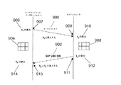
図9を参照して、登録処理は、第2のホスト端末708の第2のユーザエージェントとレジストラサーバ712との間の簡単なトランザクションを含む。第2のホスト端末708の第2のユーザエージェントは、SIP RESIGTER(レジスタ)要求メッセージ900をレジストラサーバ712へ送信する。レジストラサーバ712は、登録が完了すると、「200 OK」応答メッセージ902でリプライする。
With reference to FIG. 9, the registration process includes a simple transaction between the second user agent of the
登録遅延を測定する遠隔測定タスクの場合、第2のホスト端末708及びレジストラサーバ712は、上述したSIP−ALレジスタモジュールで適切にインスツルメントされる。
For telemetry tasks that measure registration delays, the
その結果、第1のSIP−ALレジスタモジュール(図示せず)は、SIP REGISTER要求メッセージ900の生成を検出し、SIP REGISTER要求メッセージ900は、他のシグナリングメッセージと同様に、SIPセッションを定義する送信元アドレス及び宛先アドレスと共に一意の呼IDを含む。
As a result, a first SIP-AL register module (not shown) detects the generation of a SIP
SIP REGISTER要求メッセージ900の生成を検出することによって、第1のSIP−ALレジスタモジュールがトリガされ、第1のSIP登録データ記録904が生成される。この第1のSIP登録データ記録304は、SIP REGISTER要求メッセージ900に関する情報でポピュレートされている。SIP REGISTER要求メッセージ900は、たとえば、SIP REGISTER要求メッセージ900の送信元IPアドレス及び宛先IPアドレスと、SIP REGISTER要求メッセージ900の送信元ポート番号及び宛先ポート番号と、SIP REGISTERシグナリングメッセージ900から抽出された他の部分文字列とを含む。SIP登録データ記録に必要とされるデータは構成可能であることに留意すべきである。
By detecting the generation of the SIP
その後、第1のタイムスタンプt1が計算される(ステップ906)。この第1のタイムスタンプt1は、第2のホスト端末708の第2のユーザエージェントからのSIP REGISTER要求メッセージ900の出発時刻を表す。SIP登録データ記録904は、この第1のタイムスタンプt1と共に、第2のホスト端末708の第1のアクティブキャッシュ(図示せず)に加えられる。SIP登録データ記録904は、SIP REGISTER要求メッセージ900の呼IDによってインデックスされる。
Thereafter, a first time stamp t 1 is calculated (step 906). This first time stamp t 1 represents the departure time of the SIP
次に、第1のIPv6宛先オプションヘッダ(図示せず)が生成され、SIP REGISTER要求メッセージ900のペイロードとIPv6ヘッダとの間に挿入される。この第1の宛先オプションヘッダは、第1のタイプ−長さ−値(TLV(Type-Length-Value))オブジェクトとして符号化される。SIP REGISTER要求メッセージ900のこの宛先オプションヘッダで運ばれるデータは、適切にインスツルメントされた、このメッセージの受信者により、SIPレジスタトランザクションの測定値に関係したものとして特定可能である。第1のタイムスタンプt1は、第1の宛先オプションヘッダに含まれる。SIP REGISTER要求メッセージ900は、その後、レジストラサーバ712へ送信される(ステップ907)。
Next, a first IPv6 destination option header (not shown) is generated and inserted between the payload of the SIP
SIP REGISTER要求メッセージ900が受信されると(ステップ909)、SIP REGISTER要求メッセージ900の第1の宛先オプションヘッダを構成するSIP−ALレジスタTLVオブジェクトを受信することによって、レジストラサーバ712に常駐する第2のSIP−ALレジスタモジュール(図示せず)がトリガされ、第1のSIP登録データ記録904と等しい第2のSIP登録データ記録908が生成される。これに加えて、SIP REGISTER要求メッセージ900の受信時刻を反映した第2のタイムスタンプt2が計算される(ステップ910)。第2のSIP登録データ記録908は、第1のTLVオブジェクトから抽出された第1のタイムスタンプt1及び第2のタイムスタンプt2と共に、レジストラサーバ712の第2のアクティブキャッシュ(図示せず)に記憶され、SIP REGISTER要求メッセージ900の呼IDによってインデックスされる。
When the SIP
レジストラサーバ712が、SIP REGISTER要求メッセージ900に応答できる場合、第2のSIP−ALレジスタモジュールは、レジストラサーバ712による「SIP 200 OK」応答メッセージ902の生成を検出し、「SIP 200 OK」応答メッセージ902の呼IDを使用して、レジストラサーバ712の第2のアクティブキャッシュにおいて第2のSIP登録データ記録908を突き止める。次に、SIP−ALレジスタモジュールは、レジストラサーバ712の第2のアクティブキャッシュから抽出された第2のSIP登録データ記録908から、第1のタイムスタンプt1及び第2のタイムスタンプt2を抽出し、上述した第1のIPv6宛先オプションヘッダと等しい第2のIPv6宛先オプションヘッダを構築する。次に、第2のSIP−ALレジスタモジュールは、第2のTLVオブジェクトとして符号化された第2のIPv6宛先オプションヘッダを、「SIP 200 OK」応答メッセージ902のペイロードとIPv6ヘッダとの間に追加する。この第2のTLVオブジェクトは、「SIP 200 OK」応答メッセージ902の第2の宛先オプションヘッダによって運ばれ、この場合も、そのデータは、SIPレジスタトランザクションの測定値に関係したものとして特定可能である。第2のTLVオブジェクトは、第2のタイムスタンプt2及び新たに計算された(ステップ912)第3のタイムスタンプt3を含む。この第3のタイムスタンプt3は、「SIP 200 OK」応答メッセージ902の出発時刻を表す。その後、「SIP 200 OK」応答メッセージ902が送信される(ステップ911)。
If the
最後に、「SIP 200 OK」応答メッセージ902が第2のユーザエージェントによって受信されると(ステップ913)、「SIP 200 OK」応答メッセージ902の宛先オプションヘッダを構成する第2のTLVオブジェクトによって、第1のSIP−ALレジスタモジュールがトリガされ、「SIP 200 OK」応答メッセージ902の呼IDを使用して、第2のホスト端末708の第1のアクティブキャッシュからの適切なデータ記録、すなわち、第1のSIP登録データ記録904、にアクセスし、この適切な記録を、計算された(ステップ914)第4のタイムスタンプt4、並びに、「SIP 200 OK」応答メッセージ902の第2の宛先オプションヘッダによって運ばれた第2のタイムスタンプt2及び第3のタイムスタンプt3と共に追加する。第4のタイムスタンプt4は、「SIP 200 OK」応答メッセージ902の到着時刻に対応するものである。
Finally, when the “
次に、第2のホスト端末708とレジストラサーバ712との間で共有される測定データは、その後、この例では、上述したOSSアプリケーションが第2のホスト端末708から収集することができる。収集モードは、当該技術分野で既知の任意の適切な技法とすることができ、OSSアプリケーションが第2のホスト端末708にインターロゲートすること、又は、たとえば所定の期間の満了といった所定の解放基準に従って専用パケットによりOSSアプリケーションへ測定データを送信することが含まれる。OSSアプリケーションは、測定データを所有すると、この例では、以下のメトリックの1つ又は複数のものを計算する。
Next, measurement data shared between the
・登録トランザクションの全時間t=t4−t1
・レジストラで費やされた時間tr=t3−t2
・全通過時間ttr=t−tr
・片道遅延通過時間towdreq=t2−t1及びtowdres=t4−t3
-Total time of registration transaction t = t 4 -t 1
And time spent at the registrar t r = t 3 -t 2
・ Total transit time t tr = t−t r
-One -way delayed transit time t owdreq = t 2 -t 1 and t owdres = t 4 -t 3
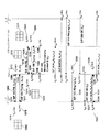
上記計算の結果は、第1のテーブル1000(図10)に記憶することができる。この第1のテーブル1000は、各ホスト端末、すなわちクライアント1002について、アクセスされたレジストラサーバの識別情報1004と、特定されたレジストラサーバで費やされた時間1006と、計算された片道遅延通過時間1008と、計算された全時間1010とを含むように編成される。測定データがレジストラサーバ712から収集された場合であっても、OSSアプリケーションは、依然として、レジストラサーバで費やされた時間tr1006及びその単一の要求の片道遅延通過時間towdreq1008を計算することができる。
The result of the calculation can be stored in the first table 1000 (FIG. 10). This first table 1000 includes, for each host terminal, ie,
OSSアプリケーションは、良好なサービス保証ツールとなるために、トランザクションの簡単な概念を抽象化し、たとえばダイアログ及びセッションといった、異なるレベルの抽象化に関する詳細な内容へのドリルダウンアクセスを可能にする。ダイアログは、たとえば呼設定又はクライアント登録といった、一群の関係したトランザクションである。セッションは、グローバルに一意の呼IDを通じて特定される完成したSIP呼を表すが、このセッションは、複数のダイアログで構成することができる。ただし、すべてのダイアログは同じ呼IDを有する。 OSS applications abstract the simple concept of transactions to be a good service assurance tool and allow drill-down access to detailed content on different levels of abstraction, such as dialogs and sessions. A dialog is a group of related transactions, such as call setup or client registration. A session represents a completed SIP call identified through a globally unique call ID, but this session can consist of multiple dialogs. However, all dialogs have the same call ID.
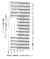
したがって、OSSアプリケーションは、収集された測定データを使用して、レジストラサーバ712の性能、及び、第2のホスト端末708の経験を評価することができる。計算の結果、すなわち、第1のテーブル1000の内容は、たとえば、棒グラフ1100(図11)として表すことができる。この棒グラフ1100は、VoIPサービスの信頼できるオペレーションを維持することを担当する技術者が容易に特定できるピーク遅延1102を示している。
Thus, the OSS application can use the collected measurement data to evaluate the performance of the
また、さまざまな測定値は、この例では第2のホスト端末708及びレジストラサーバ712といった双方の測定ポイントに分散されているので、これらの計算を行うのに必要とされるデータのほとんど、及び、付随するあらゆる特定情報が、これらの測定ポイントで利用可能であり、それによって、相関の必要性が不要となることが当業者に十分理解されよう。
Also, since the various measurements are distributed to both measurement points such as the
別の実施の形態(図12)では、第1のホスト端末702は、上述した第1のSIP−ALインバイトモジュールでインスツルメントされる。この第1のSIP−ALインバイトモジュールは、SIP INVITE XA要求メッセージ1200の生成を検出するためのものである。このSIP INVITE XA要求メッセージ1200は、SIPセッションを定義する送信元アドレス及び宛先アドレスと共に、一意の呼IDを有する。第1のSIP−ALインバイトモジュールは、SIP INVITE XA要求メッセージ1200を検出すると、第1のSIPインバイトデータ記録1202を作成し、第1のタイムスタンプt1を計算する(ステップ1204)。この第1のタイムスタンプt1は、SIP INVITE XA要求メッセージ1200の出発時刻に対応するものである。次に、第1のSIPインバイトデータ記録1202は、第1のタイムスタンプt1と共に、第1のホスト端末702の第1のアクティブキャッシュに加えられ、SIP INVITE XA要求メッセージ1200の呼IDによってインデックスされる。
In another embodiment (FIG. 12), the
また、第1のIPv6宛先オプションヘッダも生成され、SIP INVITE XA要求メッセージ1200のペイロードとIPv6ヘッダとの間に挿入される。この第1のIPv6宛先オプションヘッダは、第1のタイムスタンプt1を含むTLVオブジェクトとして符号化される。第1の宛先オプションヘッダを構成するTLVオブジェクトは、SIPインバイトトランザクションの基準(measure)に関するデータを含むものとして特定可能である。次に、SIP INVITE XA要求メッセージ1200は、プロキシサーバ704へ送信される(ステップ1206)。 A first IPv6 destination option header is also generated and inserted between the payload of the SIP INVITE X A request message 1200 and the IPv6 header. This first IPv6 destination option header is encoded as a TLV object containing a first time stamp t1. The TLV object constituting the first destination option header can be specified as including data relating to a measure of the SIP invite transaction. Next, the SIP INVITE X A request message 1200 is transmitted to the proxy server 704 (step 1206).
SIP INVITE XA要求メッセージ1200は、プロキシサーバ704によって受信される(ステップ1208)。SIP INVITE XA要求メッセージ1200に第1の宛先オプションヘッダが存在することによって、プロキシサーバ704の第2のSIP−ALインバイトモジュールがトリガされ、第1のSIPインバイトデータ記録1202と等しい第2のSIPインバイトデータ記録1210を生成する。また、SIP INVITE XA要求メッセージ1200の受信時刻に対応する第2のタイムスタンプt2も計算される(ステップ1212)。第2のSIPインバイトデータ記録1210は、TLVオブジェクトから抽出された第1のタイムスタンプt1及び第2のタイムスタンプt2と共に、プロキシサーバ704の第2のアクティブキャッシュ(図示せず)に加えられ、この場合も、SIP INVITE XA要求メッセージ1200の呼IDによってインデックスされる。
The SIP INVITE X A request message 1200 is received by the proxy server 704 (step 1208). The presence of the first destination option header in the SIP INVITE X A request message 1200 triggers the second SIP-AL invite module of the
SIP INVITE XA要求メッセージ1200、すなわち順方向、の受信の結果として作成された第2のSIPインバイトデータ記録1210の呼IDと同じ呼IDを有する後続の応答シグナリングメッセージが生成され、プロキシサーバ704において検出された場合、プロキシサーバ704の第2のSIP−ALインバイトモジュールは、第2のSIPインバイトデータ記録1210にアクセスし、第2のタイムスタンプt2を抽出する。この第2のタイムスタンプt2は、プロキシサーバ704の下流側のすぐ隣のもの、すなわち第1のホスト端末702の第1のユーザエージェント、にはまだ分配されていない。この例では、後続の応答シグナリングメッセージは、第1のホスト端末702の第1のユーザエージェントに送信される「SIP 100 試行(Trying)」応答メッセージ1214である。次に、第2のSIP−ALインバイトモジュールは、第2のIPv6宛先オプションヘッダを構築する。この第2のIPv6宛先オプションヘッダは、「SIP 100 試行」応答メッセージ1214のペイロードとIPv6ヘッダとの間に挿入される。「SIP 100 試行」応答メッセージ1214の第2の宛先オプションヘッダは、第2のTLVオブジェクトとして符号化され、適切にインスツルメントされた、このメッセージの受信者により、SIPインバイトトランザクションに関する測定データを運ぶものとして特定可能である。第2のTLVオブジェクトには、第2のタイムスタンプt2及び第3のタイムスタンプt3が提供される。この第3のタイムスタンプt3は、計算されたものであり(ステップ1216)、「SIP 100 試行」応答メッセージ1214の出発時刻に対応するものである。次に、「SIP 100 試行」応答メッセージ1214は、第1のホスト端末702の第1のユーザエージェントへ送信される(ステップ1215)。
A subsequent response signaling message having the same call ID as the call ID of the second SIP invite
第1のホスト端末702の第1のSIP−ALインバイトモジュールは、「SIP 100 試行」応答メッセージ1214を受信すると(ステップ1217)、「SIP 100 試行」応答メッセージ1214の第2の宛先オプションヘッダから第2のタイムスタンプt2及び第3のタイムスタンプt3を抽出する。また、第4のタイムスタンプt4も計算される(ステップ1218)。この第4のタイムスタンプt4は、「SIP 100 試行」応答メッセージ1214の受信時刻に対応するものである。次に、第1のSIP−ALインバイトモジュールは、第1のSIPインバイトデータ記録1202にアクセスし、第2のタイムスタンプt2、第3のタイムスタンプt3、及び第4のタイムスタンプt4を第1のSIPインバイトデータ記録1202へ追加する。
When the first SIP-AL invite module of the
他の後続の応答メッセージ、たとえば、第2のSIP−ALインバイトモジュールによって前に作成された第2のSIPインバイトデータ記録1210に記憶されたものと同じ呼IDを有する「SIP 180 呼び出し音(Ringing)」シグナリングメッセージ1219、がプロキシサーバ704によって生成された場合、第2のSIP−ALインバイトモジュールは、その後続の応答メッセージの生成を検出し、第1のホスト端末1202の第1のユーザエージェント、すなわち下流側のすぐ隣のもの、にまだ分配されていないタイムスタンプを抽出する。したがって、「SIP 100 試行」応答メッセージ1214について上述したように、第2のタイムスタンプt2が取り出される。「SIP 180 呼び出し音」シグナリングメッセージ1219の場合、前に計算された(ステップ1220)第17のタイムスタンプt17が、前に作成されてプロキシサーバ704の第2のアクティブキャッシュに記憶されている第2のSIPインバイトデータ記録1210へのアクセスを通じて取り出される。
Other subsequent response messages, eg, “
次に、第2のSIP−ALモジュールは、別のIPv6宛先オプションヘッダを構築し、このIPv6宛先オプションヘッダを後続の応答メッセージのペイロードとIPv6ヘッダとの間に挿入する。この別のIPv6宛先オプションヘッダは、別のTLVオブジェクトとして符号化され、SIPインバイトトランザクションに関する測定データを含むものとして特定可能である。また、この別のTLVオブジェクトは、これまで分配されていないタイムスタンプも含み、たとえば、「SIP 100 試行」応答メッセージ1214の場合には第2のタイムスタンプt2、又は、「SIP 180 呼び出し音」シグナリングメッセージ1219の場合には第17のタイムスタンプt17を含む。また、後続の応答メッセージの出発時刻を表す、新たに計算されたタイムスタンプも、この別のTLVオブジェクトの一部として含まれる。たとえば、「SIP 100 試行」応答メッセージ1214については、上述したように、第3のタイムスタンプt3がTLVオブジェクトに含まれる。「SIP 180 呼び出し音」シグナリングメッセージ1219の場合には、第17のタイムスタンプt17が、分配されていない唯一のタイムスタンプであるので、この別のTLVオブジェクトに含まれる唯一のタイムスタンプとなる。
The second SIP-AL module then builds another IPv6 destination option header and inserts this IPv6 destination option header between the payload of the subsequent response message and the IPv6 header. This other IPv6 destination option header is encoded as another TLV object and can be identified as containing measurement data for SIP invite transactions. This other TLV object also includes a time stamp that has not been distributed so far, for example, in the case of a “
「SIP 200 OK」応答メッセージ1220の場合、この「SIP 200 OK」応答メッセージ1221の生成は、第2のSIP−ALインバイトモジュールによって検出され、その結果、第21のタイムスタンプt21が生成される。この第21のタイムスタンプt21は、他の後続の応答メッセージについてすでに上述したのと同じ方法で、第1のホスト端末702の第1のユーザエージェントと共有される。
In the case of the “
第1のホスト端末702の第1のユーザエージェントでは、後続の応答メッセージの到着が、第1のホスト端末702の第1のSIP−ALインバイトモジュールによって検出され、その結果、第1のホスト端末702の第1のSIP−ALインバイトモジュールが、この後続の応答メッセージの到着時刻のタイムスタンプを計算する。次に、受信された後続の応答メッセージの呼IDが、第1のホスト端末702の第1のSIP−ALインバイトモジュールによって使用されて、第1のホスト端末702の第1のアクティブキャッシュに記憶された適切なSIPインバイトデータ記録がアクセスされる。次に、到着時刻のタイムスタンプが、受信された後続の応答メッセージの別の宛先オプションヘッダで運ばれたあらゆるタイムスタンプデータと共に、適切なSIPインバイトデータ記録に加えられる。したがって、「SIP 200 OK」応答メッセージ1221の受信について、第1のホスト端末702の第1のアクティブキャッシュに記憶された第1のSIPインバイト記録1202は、第1のタイムスタンプt1、第2のタイムスタンプt2、第3のタイムスタンプt3、及び第4のタイムスタンプt4、第17のタイムスタンプt17、第18のタイムスタンプt18、第21のタイムスタンプt21、並びに第22のタイムスタンプt22を含む。この第22のタイムスタンプt22は、第1のユーザ端末702の第1のユーザエージェントによる「SIP 200 OK」応答メッセージ1221の受信時刻に対応するものである。
In the first user agent of the
第1のホスト端末702の第1のユーザエージェントは、「SIP 200 OK」応答メッセージ1221に応答して、SIP ACKA要求メッセージ1222を生成する。このSIP ACKA要求メッセージ1222は、第1のホスト端末702の第1のSIP−ALインバイトモジュールによって検出される。SIP ACKA要求メッセージ1222の検出に応答して、第1のSIP−ALインバイトモジュールは、SIP ACKA要求メッセージ1222の呼IDを使用して、第1のホスト端末702の第1のアクティブキャッシュに記憶された第1のSIPインバイトデータ記録1202にアクセスする。第1のSIP−ALインバイトモジュールは、第23のタイムスタンプt23を計算する(ステップ1223)。この第23のタイムスタンプt23は、SIP ACKA要求メッセージ1222の出発時刻に対応するものである。第1のホストノード702の第1のアクティブキャッシュに記憶された第1のSIPインバイトデータ記録1202は、第23のタイムスタンプt23でポピュレートされる。次に、さらに別のIPv6宛先オプションヘッダが生成され、SIP ACKA要求メッセージ1222のペイロードとIPv6ヘッダとの間に挿入される。このさらに別の宛先オプションヘッダは、さらに別のTLVオブジェクトとして符号化される。このさらに別のTLVオブジェクトは、適切にインスツルメントされたそのTLVオブジェクトの受信者により、SIP−ALインバイトトランザクションに関する測定データを運ぶものとして特定可能である。また、このさらに別のTLVオブジェクトは、分配されていないあらゆるタイムスタンプも含み、たとえば、第4のタイムスタンプt4、第18のタイムスタンプt18、第22のタイムスタンプt22、及び第23のタイムスタンプt23を含む。次に、SIP ACKA要求メッセージ1222は、プロキシサーバ704へ送信される(ステップ1224)。
The first user agent of the
SIP ACKA要求メッセージ1222がプロキシサーバ704で受信されると(ステップ1225)、プロキシサーバ704の第2のSIP−ALインバイトモジュールは、さらに別の宛先オプションヘッダを検出し、SIP ACKA要求メッセージ1222の呼IDを使用して、プロキシサーバ704の第2のアクティブキャッシュに記憶された第2のSIPインバイトデータ記録1210にアクセスする。SIP ACKA要求メッセージ1222のこのさらに別の宛先オプションヘッダで運ばれたタイムスタンプが、そこから抽出される。SIP ACKA要求メッセージ1222の到着時刻に対応する第24のタイムスタンプt24が計算される(ステップ1226)。第2のSIPインバイトデータ記録1210は、アクセスされると、SIP ACKA要求メッセージ1222のさらに別の宛先オプションヘッダから抽出された第4のタイムスタンプt4、第18のタイムスタンプt18、第22のタイムスタンプt22、及び第23のタイムスタンプt23と共に、第24のタイムスタンプt24を含むように更新される。
When the SIP ACK A request message 1222 is received at the proxy server 704 (step 1225), the second SIP-AL invite module of the
上述した方法の測定データの分配によって第1のホスト端末702の第1のユーザエージェントとプロキシサーバ704との間で共有される測定データを使用すると、前の実施の形態について上述したのと類似の方法で、複数の有用な計算を実行して、所与のSIPセッションをサポートすることに含まれる個々のコンポーネントの性能を測定できるだけでなく、所与のSIPセッションをサポートすることに含まれる複数のコンポーネントの性能を集めることもでき、たとえば呼設定時間といった性能を測定でき、集めることができる。
Using measurement data shared between the first user agent of the
もちろん、呼設定ダイアログの一部として、プロキシサーバ704と、SIPセッションをサポートする他のコンポーネントとの間、たとえば、リダイレクトサーバ706と第2のホストノード708との間で他のメッセージが交換される。その結果、網羅的でない一例として、「SIP 100 試行」応答メッセージ1214の送信後に、プロキシサーバ704は、リダイレクトサーバ706へ送信される(ステップ1230)SIP INVITE XP要求メッセージ1228を生成する。このSIP INVITE XP要求メッセージ1228の生成は、プロキシサーバ704の第2のSIP−ALインバイトモジュールによって検出される。第2のSIP−ALインバイトモジュールは、SIP INVITE XP要求メッセージ1228を検出すると、第3のSIPインバイトデータ記録1232を作成し、第5のタイムスタンプt5を計算する(ステップ1234)。この、第5のタイムスタンプt5は、SIP INVITE XP要求メッセージ1228の出発時刻に対応するものである。次に、第3のSIPインバイトデータ記録1232は、第5のタイムスタンプt5と共に、第2のアクティブキャッシュに加えられ、SIP INVITE XP要求メッセージ1228の呼IDによってインデックスされる。また、第3のIPv6宛先オプションヘッダが生成され、SIP INVITE XP要求メッセージ1228のペイロードとIPv6ヘッダとの間に挿入される。この第3のIPv6宛先オプションヘッダは、SIPインバイトトランザクションに関する測定データを運ぶものとして特定可能なTLVオブジェクトとして符号化される。また、第5のタイムスタンプt5も、第3のTLVオブジェクトに含まれる。
Of course, as part of the call setup dialog, other messages are exchanged between the
SIP INVITE XP要求メッセージ1228がリダイレクトサーバ706によって受信される(ステップ1236)と、リダイレクトサーバ706に常駐する第3のSIP−ALインバイトモジュールは、第3の宛先オプションヘッダを検出し、SIP INVITE XP要求メッセージ1228の呼IDをインデックスとして使用して、第4のSIPインバイトデータ記録1238をリダイレクトサーバ706の第3のアクティブキャッシュに作成する。また、SIP INVITE XP要求メッセージ1228の第3の宛先オプションヘッダで運ばれた第5のタイムスタンプt5も、第3の宛先オプションヘッダから抽出され、第4のSIPインバイトデータ記録1238に加えられる。SIP ACKP要求メッセージ1228の到着時刻に対応する第6のタイムスタンプt6が計算され(ステップ1240)、第4のSIPインバイトデータ記録1238は、アクセスされると、SIP ACKA要求メッセージ1228の第3の宛先オプションヘッダから抽出された第5のタイムスタンプt5と共に、この第6のタイムスタンプt6を含むように更新される。
A SIP INVITE X P request message 1228 is received by the redirect server 706 (step 1236), the third SIP-AL Invite module resident on the
リダイレクトサーバ706は、SIP INVITE XP要求メッセージ1228の受信に応答して、第2の「SIP 100 試行」応答メッセージ1242を生成する。リダイレクトサーバ706の第3のSIP−ALインバイトモジュールは、第2の「SIP 100 試行」応答メッセージ1242の生成を検出する。第3のSIP−ALインバイトモジュールは、「SIP 100 試行」応答メッセージ1242の呼IDを使用して、第4のSIPインバイトデータ記録1238にアクセスし、第6のタイムスタンプt6を抽出する。この第6のタイムスタンプt6は、プロキシサーバ704にはまだ分配されていない。次に、第3のSIP−ALインバイトモジュールは、第4のIPv6宛先オプションヘッダを構築する。この第4のIPv6宛先オプションヘッダは、第2の「SIP 100 試行」応答メッセージ1242のペイロードとIPv6ヘッダとの間に挿入される。第4の宛先オプションヘッダは、第4のTLVオブジェクトとして符号化され、「SIP 100 試行」トランザクションに関する測定データを運ぶものとして特定可能である。第6のタイムスタンプt6、及び、第2の「SIP 100 試行」応答メッセージ1242の出発時刻に対応する計算される(ステップ1244)第7のタイムスタンプt7も、作成された第4のTLVオブジェクトに含まれる。次に、第2の「SIP 100 試行」応答メッセージ1242は、プロキシサーバ704へ送信される(ステップ1246)。
プロキシサーバ704の第2のSIP−ALインバイトモジュールは、第2の「SIP 100 試行」応答メッセージ1242を受信すると(ステップ1248)、第2の「SIP 100 試行」応答メッセージ1242の第4の宛先オプションヘッダから第6のタイムスタンプt6及び第7のタイムスタンプt7を抽出し、第3のSIPインバイトデータ記録1210にアクセスし、第6のタイムスタンプt6及び第7のタイムスタンプt7を第3のSIPインバイトデータ記録1210に追加する。
When the second SIP-AL invite module of
前述したように、プロキシサーバ704とリダイレクトサーバ706との間におけるタイムスタンプの対応する分配を伴うシグナリングメッセージの上記交換は、単なる例示であり、第1のホスト端末702と第2のホスト端末708との間でVoIP呼をセットアップするのに必要とされるダイアログは、図12において分かるように、たとえば1つ又は複数のプロキシサーバ704と第2のホスト端末708の第2のユーザエージェントとの間におけるシグナリングメッセージの他の交換を含む。
As described above, the above exchange of signaling messages with corresponding distribution of time stamps between the
通信ネットワーク700のさまざまなSIPサポートコンポーネント間で収集及び分配された測定データは、すでに上述したのと類似の方法で、さらに計算を実行して、個々のコンポーネントの性能を測定するのに使用することもできるし、所与のSIPセッションをサポートする複数のコンポーネントの性能を集めるのに使用することもできる。集められた性能の一例は、第1のホスト端末702からSIP INVITE XAシグナリングメッセージ1200を送信してから、第1のホスト端末702で「SIP 180 呼び出し音」応答メッセージを受信するまでに要する時間である。このような計算を行うために、この例では、上述したOSSアプリケーションによって、測定データが収集され、1つ又は複数のコンポーネントの性能を示す計算を実行するのに、測定データが使用される。OSSアプリケーションによって実行された計算の結果は、この例では、第2のテーブル1300(図13)に記憶される。この第2のテーブル1300は、送信元(URLタイプ)アドレス1302、宛先(URLタイプ)アドレス1304、呼ID1306、所定のシグナリングメッセージを各プロキシサーバへ送信するための時間1308、被呼び出し側クライアント時間1310(被呼び出し側端末でシグナリングメッセージの要求/応答を処理することに費やされた時間)、通過時間1312、及び全時間1314の列に編成される。第2のテーブル1300に記憶されたデータは、次に、図的に表して(図14及び図15)、呼設定時間(図14)、又は、呼設定についてのプロキシ遅延(特定のプロキシサーバでシグナリングメッセージを処理することに費やされた時間)(図15)の視覚表現を技術者に提供することができる。
Measurement data collected and distributed among the various SIP support components of the
上記例は、データを記憶する特定の方法を説明しているが、たとえばデータの編成といった記憶の方法は変更できることが十分理解されるはずである。この点で、データは、メッセージタイプ等の所与のパラメータに関連したデータのテーブルとして編成することができる。 While the above example describes a particular method of storing data, it should be appreciated that the method of storage, for example the organization of the data, can be changed. In this regard, the data can be organized as a table of data associated with a given parameter such as message type.
上記例は、パケット通信との関連で説明されているが、用語「メッセージ」は、パケット、データグラム、フレーム、セル、及びプロトコルデータユニットを包含するものとして解釈されることを目的としていることが十分理解されるはずであり、したがって、これらの用語は、交換可能であると理解されるはずである。 Although the above example has been described in the context of packet communication, the term “message” is intended to be interpreted as encompassing packets, datagrams, frames, cells, and protocol data units. It should be understood well and therefore these terms should be understood to be interchangeable.
本発明の代替的な実施の形態は、コンピュータシステムと共に使用されるコンピュータプログラム製品として実施することができる。このコンピュータプログラム製品は、たとえば、ディスケット、CD−ROM、ROM、固定ディスク等の有形のデータ記録媒体に記憶された一連のコンピュータ命令であるか、又は、コンピュータデータ信号で実施される。この信号は、有形の媒体上、又は、たとえばマイクロ波若しくは赤外線といった無線媒体上を送信される。一連のコンピュータ命令は、上述した機能のすべて又は一部を構成することができ、また、半導体デバイス、磁気デバイス、光デバイス、他のメモリデバイス等の揮発性又は不揮発性のあらゆるメモリデバイスに記憶することができる。 Alternative embodiments of the present invention may be implemented as a computer program product for use with a computer system. This computer program product is, for example, a series of computer instructions stored in a tangible data recording medium such as a diskette, CD-ROM, ROM, fixed disk or the like, or implemented with computer data signals. This signal is transmitted on a tangible medium or on a wireless medium such as microwave or infrared. The series of computer instructions can constitute all or part of the functions described above, and can be stored in any volatile or non-volatile memory device such as a semiconductor device, magnetic device, optical device, or other memory device. be able to.
702:SIPユーザエージェント(発呼)ホストA
704:SIPプロキシサーバホストP
706:SIPリダイレクトサーバ
708:SIPユーザエージェントサーバB(着呼)ホストC
710:ロケーションデータベース
712:SIPレジストラサーバ
702: SIP user agent (calling) host A
704: SIP proxy server host P
706: SIP redirect server 708: SIP user agent server B (incoming call) host C
710: Location database 712: SIP registrar server
Claims (23)
前記ハンドオーバ機構に関係した処理の一部として、前記第1のノードから前記第2のノードへ送信されるシグナリングパケットを選択するステップであって、前記シグナリングパケットが自身に関連したデータ構造定義を有する、選択するステップと、
前記シグナリングパケットを前記第2のノードへ送信する前に、前記データ構造定義に従って前記シグナリングパケットに前記測定データを組み込むステップと、を含む、方法。 A method for sharing measurement data between a first node and a second node, the measurement data being acquired by the first node and an event related to a handover mechanism of a communication network The method comprises:
Selecting a signaling packet to be transmitted from the first node to the second node as part of processing related to the handover mechanism, wherein the signaling packet has a data structure definition associated with it Step to choose,
Incorporating the measurement data into the signaling packet according to the data structure definition prior to transmitting the signaling packet to the second node.
前記シグナリングパケットから前記測定データを取得するステップと、
をさらに含む、請求項1に記載の方法。 Receiving the associated signaling packet at the second node;
Obtaining the measurement data from the signaling packet;
The method of claim 1, further comprising:
データストアと、
処理資源であって、
前記ハンドオーバ機構に関連したイベントに関する測定データを前記データストアに記録するための測定記録器と、
前記ハンドオーバ機構に関係した処理の一部を成し、且つ、使用時に、前記ハンドオーバ機構に参加する別のノードへ送信される、シグナリングパケットを特定するためのパケット選択器であって、前記シグナリングパケットが、該シグナリングパケットへの追加情報の組み込みをサポートできるデータ構造定義を有する、パケット選択器と、
前記シグナリングパケットの前記データ構造定義に従って、前記シグナリングパケットに前記測定データを組み込むためのメッセージ変更器と、
前記シグナリングパケットを前記別のノードへ転送するためのパケット転送器と、を提供するように構成される処理資源と、を備える、ネットワークノード装置。 A network node device for participating in a communication network handover mechanism,
A data store,
Processing resources,
A measurement recorder for recording measurement data relating to an event associated with the handover mechanism in the data store;
A packet selector for identifying a signaling packet that forms a part of processing related to the handover mechanism and is transmitted to another node participating in the handover mechanism when used, the signaling packet comprising: A packet selector having a data structure definition that can support the incorporation of additional information into the signaling packet;
A message modifier for incorporating the measurement data into the signaling packet according to the data structure definition of the signaling packet;
A network node device comprising: a processing resource configured to provide a packet transfer device for transferring the signaling packet to the another node.
データストアと、
処理資源であって、
前記ハンドオーバ機構、及び、シグナリングパケットのデータ構造定義による該シグナリングパケットへの測定データの組み込み、に関係した処理の一部を成す前記シグナリングパケットを受信するためのメッセージ受信機であって、前記測定データが、前記ハンドオーバ機構に関連したイベントに関係する、メッセージ受信機と、
前記シグナリングパケットから前記測定データを抽出するための測定抽出器と、
前記測定データを前記データストアに記録するためのデータ記録器と、を提供するように構成される処理資源と、を備える、ネットワークノード装置。 A network node device for participating in a communication network handover mechanism,
A data store,
Processing resources,
A message receiver for receiving the signaling packet that forms part of the processing related to the handover mechanism and the incorporation of measurement data into the signaling packet according to the data structure definition of the signaling packet, wherein the measurement data A message receiver related to an event associated with the handover mechanism;
A measurement extractor for extracting the measurement data from the signaling packet;
A network node device comprising: a processing resource configured to provide a data recorder for recording the measurement data in the data store.
前記ハンドオーバ機構に関係した処理の一部として前記第1のノードから前記第2のノードへ送信されるシグナリングパケットを選択するためのパケット選択器であって、前記シグナリングパケットが、該シグナリングパケットに関連したデータ構造定義を有する、パケット選択器と、
前記シグナリングパケットを前記第2のノードへ送信する前に、前記データ構造定義に従って、前記シグナリングパケットに前記測定データを組み込むためのパケット変更器と、を備える、システム。 A system for sharing measurement data between a first node and a second node, wherein the measurement data is acquired by the first node at the time of use, and is a handover of a communication network Related to the mechanism related events, the system
A packet selector for selecting a signaling packet to be transmitted from the first node to the second node as part of processing related to the handover mechanism, wherein the signaling packet is associated with the signaling packet A packet selector having a defined data structure definition;
A packet modifier for incorporating the measurement data into the signaling packet according to the data structure definition before transmitting the signaling packet to the second node.
SIPトランザクションに関係した処理の一部として、前記第1のノードから前記第2のノードへ送信されるシグナリングパケットを選択するステップであって、前記シグナリングパケットが自身に関連したデータ構造定義を有する、選択するステップと、
前記シグナリングパケットを前記第2のノードへ送信する前に、前記データ構造定義に従って前記シグナリングパケットに前記測定データを組み込むステップと、を含む、方法。 A method for sharing measurement data between a first node and a second node, the measurement data being obtained by the first node and associated with a SIP signaling transaction of a communication network Related to events, the method
Selecting a signaling packet to be transmitted from the first node to the second node as part of a process related to a SIP transaction, the signaling packet having a data structure definition associated with it; A step to choose;
Incorporating the measurement data into the signaling packet according to the data structure definition prior to transmitting the signaling packet to the second node.
前記シグナリングパケットから前記測定データを取得するステップと、をさらに含む、請求項9に記載の方法。 Receiving the signaling packet at the second node;
The method according to claim 9, further comprising obtaining the measurement data from the signaling packet.
請求項9ないし13のいずれか1項に記載の前記第1のノードと前記第2のノードとの間で測定データを共有する前記方法に従って、前記第1の対の通信ノードの間で測定データを共有するステップであって、前記第1の対の通信ノードは、前記第1のノード及び前記第2のノードに対応する、共有するステップ、を含む、方法。 A method of measuring network performance for a plurality of nodes of a communication network, wherein the plurality of nodes includes a first pair of communication nodes, the first pair of communication nodes participating in a signaling transaction of SIP communication; The method
14. Measurement data between the first pair of communication nodes according to the method of sharing measurement data between the first node and the second node according to any one of claims 9-13. Sharing the first pair of communication nodes corresponding to the first node and the second node.
請求項9乃至13のいずれか1項に記載の前記第1のノードと前記第2のノードとの間で測定データを共有する前記方法に従って、前記第2の対の通信ノードの間で測定データを共有するステップであって、前記第2の対の通信ノードは、前記第1のノード及び前記第2のノードに対応する、共有するステップ、
をさらに含む、請求項14に記載の通信ネットワークの複数のノードに関するネットワーク性能を測定する方法。 The plurality of nodes includes a second pair of communication nodes, the second pair of communication nodes participating in the signaling transaction of the SIP communication, the method comprising:
14. Measurement data between the second pair of communication nodes according to the method of sharing measurement data between the first node and the second node according to any one of claims 9-13. Sharing the second pair of communication nodes corresponding to the first node and the second node;
15. The method of measuring network performance for a plurality of nodes of a communication network according to claim 14, further comprising:
をさらに含む、請求項14乃至16のいずれか1項に記載の通信ネットワークの複数のノードに関するネットワーク性能を測定する方法。 Communicating the measurement data to a remote monitoring application;
The method of measuring network performance for a plurality of nodes of a communication network according to any one of claims 14 to 16, further comprising:
データストアと、
処理資源であって、
前記SIPトランザクションに関連したイベントに関する測定データを前記データストアに記録するための測定記録器と、
前記SIPトランザクションに関係した処理の一部を成し、且つ、使用時に、前記SIPトランザクションに参加する別のノードへ送信される、シグナリングパケットを特定するためのパケット選択器であって、前記シグナリングパケットが、該シグナリングパケットへの追加情報の組み込みをサポートできるデータ構造定義を有する、パケット選択器と、
前記シグナリングパケットの前記データ構造定義に従って、前記シグナリングパケットに前記測定データを組み込むためのメッセージ変更器と、
前記シグナリングパケットを前記別のノードへ転送するためのパケット転送器と、を提供するように構成される処理資源と、を備える、ネットワークノード装置。 A network node device for participating in a SIP signaling transaction of a communication network,
A data store,
Processing resources,
A measurement recorder for recording measurement data relating to an event associated with the SIP transaction in the data store;
A packet selector for identifying a signaling packet that forms part of a process related to the SIP transaction and is transmitted to another node participating in the SIP transaction when used, the signaling packet comprising: A packet selector having a data structure definition that can support the incorporation of additional information into the signaling packet;
A message modifier for incorporating the measurement data into the signaling packet according to the data structure definition of the signaling packet;
A network node device comprising: a processing resource configured to provide a packet transfer device for transferring the signaling packet to the another node.
データストアと、
処理資源であって、
前記SIPトランザクション、及び、シグナリングパケットのデータ構造定義による該シグナリングパケットへの測定データの組み込み、に関係した処理の一部を成す前記シグナリングパケットを受信するためのメッセージ受信機であって、前記測定データが、前記SIPトランザクションに関連したイベントに関係する、メッセージ受信機と、
前記シグナリングパケットから前記測定データを抽出するための測定抽出器と、
前記測定データを前記データストアに記録するためのデータ記録器と、を提供するように構成される処理資源と、を備える、ネットワークノード装置。 A network node device for participating in a SIP signaling transaction of a communication network,
A data store,
Processing resources,
A message receiver for receiving the signaling packet that forms part of a process related to the SIP transaction and the incorporation of measurement data into the signaling packet according to the data structure definition of the signaling packet, the measurement data A message receiver related to an event associated with the SIP transaction;
A measurement extractor for extracting the measurement data from the signaling packet;
A network node device comprising: a processing resource configured to provide a data recorder for recording the measurement data in the data store.
前記SIPトランザクションに関係した処理の一部として、前記第1のノードから前記第2のノードへ送信されるシグナリングパケットを選択するためのパケット選択器であって、前記シグナリングパケットが該シグナリングパケットに関連したデータ構造定義を有する、パケット選択器と、
前記シグナリングパケットを前記第2のノードへ送信する前に、前記データ構造定義に従って、前記シグナリングパケットに前記測定データを組み込むためのパケット変更器と、を備える、システム。 A system for sharing measurement data between a first node and a second node, wherein the measurement data is acquired by the first node at the time of use, and SIP of a communication network Related to events related to signaling transactions, the system
A packet selector for selecting a signaling packet to be transmitted from the first node to the second node as part of a process related to the SIP transaction, wherein the signaling packet is associated with the signaling packet; A packet selector having a defined data structure definition;
A packet modifier for incorporating the measurement data into the signaling packet according to the data structure definition before transmitting the signaling packet to the second node.
請求項22に記載の前記第1のノードと前記第2のノードとの間で測定データを共有するための前記システムであって、前記第1の対の通信ノードは、前記第1のノード及び前記第2のノードに対応する、前記システム、を備える、システム。 A system for measuring network performance for a plurality of nodes of a communication network, wherein the plurality of nodes includes a first pair of communication nodes, wherein the first pair of communication nodes, in use, is configured for SIP communication. Participating in a signaling transaction, the system
23. The system for sharing measurement data between the first node and the second node according to claim 22, wherein the first pair of communication nodes includes the first node and A system corresponding to the second node.
Applications Claiming Priority (1)
| Application Number | Priority Date | Filing Date | Title |
|---|---|---|---|
| GB0506789A GB2425018A (en) | 2005-04-04 | 2005-04-04 | Method of sharing measurement data |
Publications (2)
| Publication Number | Publication Date |
|---|---|
| JP2006304288A true JP2006304288A (en) | 2006-11-02 |
| JP2006304288A5 JP2006304288A5 (en) | 2009-05-07 |
Family
ID=34586654
Family Applications (1)
| Application Number | Title | Priority Date | Filing Date |
|---|---|---|---|
| JP2006094816A Ceased JP2006304288A (en) | 2005-04-04 | 2006-03-30 | Method of sharing measurement data, system therefor and network node apparatus |
Country Status (4)
| Country | Link |
|---|---|
| US (1) | US20060221837A1 (en) |
| EP (1) | EP1710977A1 (en) |
| JP (1) | JP2006304288A (en) |
| GB (1) | GB2425018A (en) |
Cited By (2)
| Publication number | Priority date | Publication date | Assignee | Title |
|---|---|---|---|---|
| WO2008117725A1 (en) * | 2007-03-27 | 2008-10-02 | Nec Corporation | Communication system, address management method, address management server, gateway, and program |
| WO2012164675A1 (en) | 2011-05-30 | 2012-12-06 | 富士通株式会社 | Wireless communication system, base station, gateway, and wireless communication method |
Families Citing this family (24)
| Publication number | Priority date | Publication date | Assignee | Title |
|---|---|---|---|---|
| US9197857B2 (en) | 2004-09-24 | 2015-11-24 | Cisco Technology, Inc. | IP-based stream splicing with content-specific splice points |
| US8966551B2 (en) | 2007-11-01 | 2015-02-24 | Cisco Technology, Inc. | Locating points of interest using references to media frames within a packet flow |
| WO2007064880A2 (en) * | 2005-12-01 | 2007-06-07 | Firestar Software, Inc. | System and method for exchanging information among exchange applications |
| JP4520432B2 (en) * | 2006-06-15 | 2010-08-04 | Okiセミコンダクタ株式会社 | VoIP network system for packet communication by multicast and its construction method |
| US8548470B2 (en) * | 2006-07-24 | 2013-10-01 | Samsung Electronics Co., Ltd. | Mechanism for the conveyance and management of device mobility in an IMS network |
| US8571198B2 (en) * | 2006-10-10 | 2013-10-29 | Cisco Technology, Inc. | Handling redirect calls |
| US8745185B1 (en) | 2006-10-12 | 2014-06-03 | Timothy J. Salo | Method and apparatus for providing semantically aware network services |
| US7936695B2 (en) * | 2007-05-14 | 2011-05-03 | Cisco Technology, Inc. | Tunneling reports for real-time internet protocol media streams |
| US8023419B2 (en) * | 2007-05-14 | 2011-09-20 | Cisco Technology, Inc. | Remote monitoring of real-time internet protocol media streams |
| US7835406B2 (en) | 2007-06-18 | 2010-11-16 | Cisco Technology, Inc. | Surrogate stream for monitoring realtime media |
| US7817546B2 (en) | 2007-07-06 | 2010-10-19 | Cisco Technology, Inc. | Quasi RTP metrics for non-RTP media flows |
| EP2253153A1 (en) * | 2008-03-03 | 2010-11-24 | Panasonic Corporation | Information exchange between gateways for route optimization with network-based mobility management |
| US8352591B2 (en) * | 2009-03-16 | 2013-01-08 | Verizon Patent And Licensing Inc. | Presence network agent in IMS networks |
| CN101594182A (en) * | 2009-06-15 | 2009-12-02 | 中兴通讯股份有限公司 | In ASON, realize the method and system of signaling tracing |
| US8301982B2 (en) | 2009-11-18 | 2012-10-30 | Cisco Technology, Inc. | RTP-based loss recovery and quality monitoring for non-IP and raw-IP MPEG transport flows |
| US8135866B2 (en) | 2010-01-22 | 2012-03-13 | Research In Motion Limited | System and method for detecting and processing stale messages |
| US8819714B2 (en) | 2010-05-19 | 2014-08-26 | Cisco Technology, Inc. | Ratings and quality measurements for digital broadcast viewers |
| US20120102134A1 (en) * | 2010-10-21 | 2012-04-26 | International Business Machines Corporation | Cache sharing among branch proxy servers via a master proxy server at a data center |
| EP2590366B1 (en) * | 2011-11-02 | 2020-06-10 | Software AG | Method, computer program and system for monitoring message objects sent from a client to invoke operations on a server in a distributed computing environment |
| US9298753B2 (en) * | 2013-05-31 | 2016-03-29 | Wal-Mart Stores, Inc. | Resolving pairwise links to groups |
| US20150071091A1 (en) * | 2013-09-12 | 2015-03-12 | Alcatel-Lucent Usa Inc. | Apparatus And Method For Monitoring Network Performance |
| CN106603322B (en) * | 2015-10-20 | 2020-08-14 | 华为技术有限公司 | Message sending and receiving method and network equipment |
| US10069871B2 (en) * | 2016-02-01 | 2018-09-04 | Verizon Patent And Licensing Inc. | Measuring session initiation protocol (SIP) messaging latency |
| US11606273B1 (en) * | 2021-05-24 | 2023-03-14 | Juniper Networks, Inc. | Monitoring server performance using server processing time |
Citations (6)
| Publication number | Priority date | Publication date | Assignee | Title |
|---|---|---|---|---|
| JP2000295276A (en) * | 1999-04-02 | 2000-10-20 | Hitachi Ltd | Communication control system |
| JP2002016599A (en) * | 1999-12-02 | 2002-01-18 | Hitachi Ltd | Network measurement control system and network measurement control method |
| JP2002368790A (en) * | 2001-06-11 | 2002-12-20 | Fujitsu Ltd | Router adaptable to mobile terminal |
| JP2004112791A (en) * | 2002-09-16 | 2004-04-08 | Agilent Technol Inc | Method of measuring network operation parameter |
| JP2004186989A (en) * | 2002-12-03 | 2004-07-02 | Hitachi Ltd | Mobile terminal, and inter-terminal packet communication method |
| JP2004282108A (en) * | 2000-11-22 | 2004-10-07 | Lucent Technol Inc | Scheduling method for data flow in packet switched cellular system |
Family Cites Families (6)
| Publication number | Priority date | Publication date | Assignee | Title |
|---|---|---|---|---|
| US6038533A (en) * | 1995-07-07 | 2000-03-14 | Lucent Technologies Inc. | System and method for selecting training text |
| US7142512B1 (en) * | 1999-12-02 | 2006-11-28 | Hitachi, Ltd. | Network measurement controlling system apparatus and method |
| US6862446B2 (en) * | 2003-01-31 | 2005-03-01 | Flarion Technologies, Inc. | Methods and apparatus for the utilization of core based nodes for state transfer |
| WO2005015934A1 (en) * | 2003-08-07 | 2005-02-17 | Telefonaktiebolaget Lm Ericsson (Publ) | Location signaling for large-scale, end-to-end, quality-of-service monitoring of mobile telecommunication networks |
| US7385924B1 (en) * | 2003-09-30 | 2008-06-10 | Packeteer, Inc. | Enhanced flow data records including traffic type data |
| US7554983B1 (en) * | 2004-12-20 | 2009-06-30 | Packeteer, Inc. | Probing hosts against network application profiles to facilitate classification of network traffic |
-
2005
- 2005-04-04 GB GB0506789A patent/GB2425018A/en not_active Withdrawn
-
2006
- 2006-03-20 US US11/384,938 patent/US20060221837A1/en not_active Abandoned
- 2006-03-30 JP JP2006094816A patent/JP2006304288A/en not_active Ceased
- 2006-03-30 EP EP06112048A patent/EP1710977A1/en not_active Withdrawn
Patent Citations (6)
| Publication number | Priority date | Publication date | Assignee | Title |
|---|---|---|---|---|
| JP2000295276A (en) * | 1999-04-02 | 2000-10-20 | Hitachi Ltd | Communication control system |
| JP2002016599A (en) * | 1999-12-02 | 2002-01-18 | Hitachi Ltd | Network measurement control system and network measurement control method |
| JP2004282108A (en) * | 2000-11-22 | 2004-10-07 | Lucent Technol Inc | Scheduling method for data flow in packet switched cellular system |
| JP2002368790A (en) * | 2001-06-11 | 2002-12-20 | Fujitsu Ltd | Router adaptable to mobile terminal |
| JP2004112791A (en) * | 2002-09-16 | 2004-04-08 | Agilent Technol Inc | Method of measuring network operation parameter |
| JP2004186989A (en) * | 2002-12-03 | 2004-07-02 | Hitachi Ltd | Mobile terminal, and inter-terminal packet communication method |
Cited By (2)
| Publication number | Priority date | Publication date | Assignee | Title |
|---|---|---|---|---|
| WO2008117725A1 (en) * | 2007-03-27 | 2008-10-02 | Nec Corporation | Communication system, address management method, address management server, gateway, and program |
| WO2012164675A1 (en) | 2011-05-30 | 2012-12-06 | 富士通株式会社 | Wireless communication system, base station, gateway, and wireless communication method |
Also Published As
| Publication number | Publication date |
|---|---|
| EP1710977A1 (en) | 2006-10-11 |
| US20060221837A1 (en) | 2006-10-05 |
| GB2425018A (en) | 2006-10-11 |
| GB0506789D0 (en) | 2005-05-11 |
Similar Documents
| Publication | Publication Date | Title |
|---|---|---|
| JP2006304288A (en) | Method of sharing measurement data, system therefor and network node apparatus | |
| JP2006287934A (en) | Method for monitoring signaling message progress and network monitoring unit | |
| JP3633430B2 (en) | COMMUNICATION METHOD, COMMUNICATION SYSTEM, COMMUNICATION DEVICE, AND RECORDING MEDIUM | |
| US7324499B1 (en) | Method and system for automatic call monitoring in a wireless network | |
| CA2469169C (en) | Method and apparatus for determination of network topology | |
| JP3994103B2 (en) | Optimal information transfer related to IP session relocation in mobile communication systems | |
| JP4579934B2 (en) | Addressing method and apparatus for establishing a Host Identity Protocol (HIP) connection between a legacy node and a HIP node | |
| EP1772998A2 (en) | Method for a wireless station to determine network metrics prior to associating with an access point | |
| JP4430106B2 (en) | System and method for providing IPv6 service | |
| US20230300051A1 (en) | In-band Edge-to-Edge Round-Trip Time Measurement | |
| AU2003265860B2 (en) | Method for a wireless station to determine network metrics prior to associating with an access point | |
| WO2012000366A1 (en) | Relay method for service data and relay node system | |
| Bokor et al. | Design and evaluation of host identity protocol (HIP) simulation framework for INET/OMNeT++ | |
| JP4463838B2 (en) | Method and apparatus for setting service device elements in a network | |
| Schmidt et al. | Roaming Real-Time Applications-Mobility Services in IPv6 Networks | |
| JP2001320416A (en) | Quality information measurement method and system in mobile packet communication, and quality information providing method and system | |
| Dhraief et al. | A service-oriented framework for mobility and multihoming support | |
| US20230327983A1 (en) | Performance measurement in a segment routing network | |
| JP3861885B2 (en) | Mobile terminal and packet transmission method | |
| JP3861903B2 (en) | Mobile terminal and packet transmission method | |
| JP4169036B2 (en) | Mobility support device | |
| Bokor et al. | Protocol design and analysis of a HIP-based per-application mobility management platform | |
| JP4169037B2 (en) | Transfer registration method | |
| CN116506369A (en) | Dual-stack network flow scheduling method | |
| JP4208030B2 (en) | Mobile terminal, movement support apparatus, and network system |
Legal Events
| Date | Code | Title | Description |
|---|---|---|---|
| RD02 | Notification of acceptance of power of attorney |
Free format text: JAPANESE INTERMEDIATE CODE: A7422 Effective date: 20070511 |
|
| A521 | Request for written amendment filed |
Free format text: JAPANESE INTERMEDIATE CODE: A523 Effective date: 20090324 |
|
| A621 | Written request for application examination |
Free format text: JAPANESE INTERMEDIATE CODE: A621 Effective date: 20090324 |
|
| A131 | Notification of reasons for refusal |
Free format text: JAPANESE INTERMEDIATE CODE: A131 Effective date: 20100928 |
|
| A521 | Request for written amendment filed |
Free format text: JAPANESE INTERMEDIATE CODE: A523 Effective date: 20101228 |
|
| A01 | Written decision to grant a patent or to grant a registration (utility model) |
Free format text: JAPANESE INTERMEDIATE CODE: A01 Effective date: 20110308 |
|
| A045 | Written measure of dismissal of application [lapsed due to lack of payment] |
Free format text: JAPANESE INTERMEDIATE CODE: A045 Effective date: 20110722 |