JP2006296635A - Endoscope apparatus - Google Patents
Endoscope apparatus Download PDFInfo
- Publication number
- JP2006296635A JP2006296635A JP2005120895A JP2005120895A JP2006296635A JP 2006296635 A JP2006296635 A JP 2006296635A JP 2005120895 A JP2005120895 A JP 2005120895A JP 2005120895 A JP2005120895 A JP 2005120895A JP 2006296635 A JP2006296635 A JP 2006296635A
- Authority
- JP
- Japan
- Prior art keywords
- excitation
- light
- endoscope apparatus
- fluorescence
- wavelength
- Prior art date
- Legal status (The legal status is an assumption and is not a legal conclusion. Google has not performed a legal analysis and makes no representation as to the accuracy of the status listed.)
- Pending
Links
Images


Classifications
-
- A—HUMAN NECESSITIES
- A61—MEDICAL OR VETERINARY SCIENCE; HYGIENE
- A61B—DIAGNOSIS; SURGERY; IDENTIFICATION
- A61B5/00—Measuring for diagnostic purposes; Identification of persons
- A61B5/0059—Measuring for diagnostic purposes; Identification of persons using light, e.g. diagnosis by transillumination, diascopy, fluorescence
- A61B5/0071—Measuring for diagnostic purposes; Identification of persons using light, e.g. diagnosis by transillumination, diascopy, fluorescence by measuring fluorescence emission
-
- A—HUMAN NECESSITIES
- A61—MEDICAL OR VETERINARY SCIENCE; HYGIENE
- A61B—DIAGNOSIS; SURGERY; IDENTIFICATION
- A61B1/00—Instruments for performing medical examinations of the interior of cavities or tubes of the body by visual or photographical inspection, e.g. endoscopes; Illuminating arrangements therefor
- A61B1/00002—Operational features of endoscopes
- A61B1/00004—Operational features of endoscopes characterised by electronic signal processing
- A61B1/00009—Operational features of endoscopes characterised by electronic signal processing of image signals during a use of endoscope
- A61B1/000094—Operational features of endoscopes characterised by electronic signal processing of image signals during a use of endoscope extracting biological structures
-
- A—HUMAN NECESSITIES
- A61—MEDICAL OR VETERINARY SCIENCE; HYGIENE
- A61B—DIAGNOSIS; SURGERY; IDENTIFICATION
- A61B1/00—Instruments for performing medical examinations of the interior of cavities or tubes of the body by visual or photographical inspection, e.g. endoscopes; Illuminating arrangements therefor
- A61B1/00163—Optical arrangements
- A61B1/00186—Optical arrangements with imaging filters
-
- A—HUMAN NECESSITIES
- A61—MEDICAL OR VETERINARY SCIENCE; HYGIENE
- A61B—DIAGNOSIS; SURGERY; IDENTIFICATION
- A61B1/00—Instruments for performing medical examinations of the interior of cavities or tubes of the body by visual or photographical inspection, e.g. endoscopes; Illuminating arrangements therefor
- A61B1/04—Instruments for performing medical examinations of the interior of cavities or tubes of the body by visual or photographical inspection, e.g. endoscopes; Illuminating arrangements therefor combined with photographic or television appliances
- A61B1/043—Instruments for performing medical examinations of the interior of cavities or tubes of the body by visual or photographical inspection, e.g. endoscopes; Illuminating arrangements therefor combined with photographic or television appliances for fluorescence imaging
-
- A—HUMAN NECESSITIES
- A61—MEDICAL OR VETERINARY SCIENCE; HYGIENE
- A61B—DIAGNOSIS; SURGERY; IDENTIFICATION
- A61B1/00—Instruments for performing medical examinations of the interior of cavities or tubes of the body by visual or photographical inspection, e.g. endoscopes; Illuminating arrangements therefor
- A61B1/06—Instruments for performing medical examinations of the interior of cavities or tubes of the body by visual or photographical inspection, e.g. endoscopes; Illuminating arrangements therefor with illuminating arrangements
- A61B1/0638—Instruments for performing medical examinations of the interior of cavities or tubes of the body by visual or photographical inspection, e.g. endoscopes; Illuminating arrangements therefor with illuminating arrangements providing two or more wavelengths
-
- A—HUMAN NECESSITIES
- A61—MEDICAL OR VETERINARY SCIENCE; HYGIENE
- A61B—DIAGNOSIS; SURGERY; IDENTIFICATION
- A61B1/00—Instruments for performing medical examinations of the interior of cavities or tubes of the body by visual or photographical inspection, e.g. endoscopes; Illuminating arrangements therefor
- A61B1/06—Instruments for performing medical examinations of the interior of cavities or tubes of the body by visual or photographical inspection, e.g. endoscopes; Illuminating arrangements therefor with illuminating arrangements
- A61B1/0646—Instruments for performing medical examinations of the interior of cavities or tubes of the body by visual or photographical inspection, e.g. endoscopes; Illuminating arrangements therefor with illuminating arrangements with illumination filters
-
- A—HUMAN NECESSITIES
- A61—MEDICAL OR VETERINARY SCIENCE; HYGIENE
- A61B—DIAGNOSIS; SURGERY; IDENTIFICATION
- A61B1/00—Instruments for performing medical examinations of the interior of cavities or tubes of the body by visual or photographical inspection, e.g. endoscopes; Illuminating arrangements therefor
- A61B1/06—Instruments for performing medical examinations of the interior of cavities or tubes of the body by visual or photographical inspection, e.g. endoscopes; Illuminating arrangements therefor with illuminating arrangements
- A61B1/0661—Endoscope light sources
- A61B1/0669—Endoscope light sources at proximal end of an endoscope
-
- A—HUMAN NECESSITIES
- A61—MEDICAL OR VETERINARY SCIENCE; HYGIENE
- A61B—DIAGNOSIS; SURGERY; IDENTIFICATION
- A61B5/00—Measuring for diagnostic purposes; Identification of persons
- A61B5/0059—Measuring for diagnostic purposes; Identification of persons using light, e.g. diagnosis by transillumination, diascopy, fluorescence
- A61B5/0082—Measuring for diagnostic purposes; Identification of persons using light, e.g. diagnosis by transillumination, diascopy, fluorescence adapted for particular medical purposes
- A61B5/0084—Measuring for diagnostic purposes; Identification of persons using light, e.g. diagnosis by transillumination, diascopy, fluorescence adapted for particular medical purposes for introduction into the body, e.g. by catheters
Landscapes
- Life Sciences & Earth Sciences (AREA)
- Health & Medical Sciences (AREA)
- Surgery (AREA)
- Engineering & Computer Science (AREA)
- Biophysics (AREA)
- Public Health (AREA)
- Veterinary Medicine (AREA)
- Physics & Mathematics (AREA)
- Pathology (AREA)
- General Health & Medical Sciences (AREA)
- Animal Behavior & Ethology (AREA)
- Biomedical Technology (AREA)
- Heart & Thoracic Surgery (AREA)
- Medical Informatics (AREA)
- Molecular Biology (AREA)
- Radiology & Medical Imaging (AREA)
- Optics & Photonics (AREA)
- Nuclear Medicine, Radiotherapy & Molecular Imaging (AREA)
- Signal Processing (AREA)
- Endoscopes (AREA)
- Investigating, Analyzing Materials By Fluorescence Or Luminescence (AREA)
Abstract
Description
本発明は蛍光観察を行う内視鏡装置に関する。 The present invention relates to an endoscope apparatus that performs fluorescence observation.
従来、生体内の病変の診断を行うために、生体内の組織を観察する内視鏡装置が広く知られている。そのような内視鏡装置としては、白色光等の通常光を用いて生体内の組織を撮像して観察画像を取得し、モニタ等に表示して観察する電子撮像式の内視鏡装置が広く実用化されている。また、これに加えて、生体内の組織を光源からの励起光で照射することにより励起し、生体の組織から発した蛍光を撮像光学系を介して撮像素子上に結像することで蛍光画像を取得するようにした蛍光内視鏡装置が知られている。 2. Description of the Related Art Conventionally, endoscope apparatuses that observe tissue in a living body in order to diagnose a lesion in the living body are widely known. As such an endoscope apparatus, there is an electronic imaging type endoscope apparatus that captures an in-vivo tissue using normal light such as white light, acquires an observation image, and displays and observes the image on a monitor or the like. Widely used. In addition, a fluorescent image is obtained by exciting a tissue in a living body with irradiation light from a light source and imaging fluorescence emitted from the living tissue on an image sensor through an imaging optical system. There is known a fluorescence endoscope apparatus that acquires the above-mentioned information.
蛍光内視鏡装置は、取得した蛍光情報に基づいて生体組織を診断するために用いられる。例えば、励起光を生体組織に照射した場合、正常組織と腫瘍等の病変組織とでは、血流や粘膜厚や組織の機構が異なるため、発する自家蛍光の強度が異なる。そこで、蛍光内視鏡装置を用いた一診断手法として、この自家蛍光を病変の検出を特徴づける要素として利用する方法が知られている。すなわち、生体組織に励起光を照射して、生体に元来存在する自家蛍光を生じさせて、この自家蛍光を取得し、取得した蛍光情報に基づいて、生体組織の病変の有無を診断する。
また、蛍光内視鏡装置を用いた他の診断手法として、腫瘍親和性を有し、光により励起されたとき蛍光を発する蛍光物質(蛍光薬剤など)を生体の外部から腫瘍部分に投与して吸収させておき、その部分に励起光を照射して蛍光を生じさせて、この蛍光を取得し、取得した蛍光情報に基づいて、腫瘍の有無を診断する方法も知られている。
The fluorescence endoscope apparatus is used for diagnosing a living tissue based on acquired fluorescence information. For example, when a living tissue is irradiated with excitation light, the intensity of autofluorescence emitted differs between a normal tissue and a diseased tissue such as a tumor because the blood flow, mucosal thickness, and tissue mechanism are different. Therefore, as one diagnostic method using a fluorescence endoscope apparatus, a method of using this autofluorescence as an element characterizing lesion detection is known. That is, the living tissue is irradiated with excitation light to generate autofluorescence originally present in the living body, the autofluorescence is acquired, and the presence or absence of a lesion in the living tissue is diagnosed based on the acquired fluorescence information.
In addition, as another diagnostic method using a fluorescence endoscope apparatus, a fluorescent substance (fluorescent agent, etc.) having tumor affinity and emitting fluorescence when excited by light is administered to the tumor part from outside the living body. A method is also known in which absorption is performed, excitation light is irradiated to the portion to generate fluorescence, the fluorescence is acquired, and the presence or absence of a tumor is diagnosed based on the acquired fluorescence information.
蛍光内視鏡装置は、一般的に、蛍光物質(自家蛍光物質、蛍光薬剤などの蛍光物質)を励起する波長を生体に照射する励起光照射部と、生体から発した蛍光を検出する蛍光検出部とで構成されている。励起光照射部は、蛍光物質を励起する波長を発する光源部と光源部で発した光を生体に導く照明光学系を有している。蛍光検出部は、生体の蛍光像を結像する結像光学系と、結像した蛍光像を撮像する撮像素子を有している。また、生体から撮像素子との間には励起光の波長を遮光し、蛍光を透過させるための励起波長遮断フィルターが設けられている。その他、撮像素子には画像処理装置及びモニタ等の表示装置が接続されており、撮像した蛍光画像を表示することができるようになっている。 In general, a fluorescence endoscope apparatus has an excitation light irradiation unit that irradiates a living body with a wavelength that excites a fluorescent substance (fluorescent substance such as an autofluorescent substance or a fluorescent drug), and fluorescence detection that detects fluorescence emitted from the living body. It consists of parts. The excitation light irradiation unit has a light source unit that emits a wavelength for exciting the fluorescent material and an illumination optical system that guides light emitted from the light source unit to the living body. The fluorescence detection unit includes an imaging optical system that forms a fluorescent image of a living body and an image sensor that captures the formed fluorescent image. In addition, an excitation wavelength blocking filter is provided between the living body and the image sensor to block the wavelength of excitation light and transmit fluorescence. In addition, an image processing device and a display device such as a monitor are connected to the imaging element so that the captured fluorescent image can be displayed.
上述したように、蛍光観察の対象となる蛍光物質には、生体内の元来存在する自家蛍光物質と、薬剤として外部から生体に投与される蛍光物質(蛍光薬剤)とがある。自家蛍光物質には、互いに異なる波長で蛍光を発する複数の蛍光物質が存在する。また、蛍光薬剤にも、互いに異なる波長で蛍光を発する複数の物質が存在する。そこで、これらの蛍光物質を個別に検出するために異なる波長領域で蛍光観察を行うようにした技術が、例えば、次の特許文献1及び2に提案されている。
特許文献1には、複数の波長領域の自家蛍光を検出するように構成された蛍光内視鏡装置が開示されている。
また、特許文献2には、複数の蛍光薬剤を生体に投与して、複数の波長領域の蛍光を検出する技術が開示されている。
Patent Document 2 discloses a technique for detecting fluorescence in a plurality of wavelength regions by administering a plurality of fluorescent agents to a living body.
しかし、従来の蛍光観察を用いた診断では、特許文献1,2のいずれの技術も、励起光として一つの波長帯域の光のみしか使用していない。生体由来の自家蛍光物質は、表1に示すように、励起光の吸収スペクトルのピーク波長が著しく離れているものもある。また同様に、蛍光薬剤として有用である有機色素のような蛍光物質も、図16に示すように、励起光の吸収スペクトルのピーク波長が著しく離れている。このため、励起することのできる蛍光物質の種類やその数が非常に限られていた。従って、従来の蛍光観察を用いた診断では、例えばガンなどの病変に由来する要素に関する情報が不足し、ガンなどの病変を特徴付ける確率を十分に高くとることができず、診断能に一定の限界があった。
表1

Table 1
また、従来の励起光として一つの波長帯域の光のみ使用して複数の蛍光物質を励起する手法においては、互いに異なる波長で蛍光を発する複数の物質を個別に検出するために、例えば、図17に示すようにファイバースコープ106を用い、ダイクロイックミラー120やバンドパスフィルター124,128を用いて、検出する波長別に複数の撮像素子126,130を用いる構造の内視鏡装置が採用されている。そして、現在、先端に撮像素子が配置されたビデオ内視鏡装置が主流となっている。この種の内視鏡装置は、画素数が100万画素にも及ぶものもあり、非常に高精細な画像が得られ、ガンを含む様々な病態診断等に非常に有用となっているためである。ところが、従来の蛍光内視鏡装置で用いられている観察系がファイバー式のスコープでは、画素数が数万本程度と著しく少ないため物体の解像力が低くなり、診断に有用な病変部の微細な構造情報が得られないという問題があった。このように、従来の蛍光内視鏡装置では、複数の波長の蛍光を検出するために、その検出する蛍光数と同じ数のフィルターや撮像素子が必要であり、ビデオ内視鏡装置を実現する上で必要な小型化のための工夫がなされていなかった。また、蛍光検出器の構成が複雑なため組立作業性が悪く、また複数の撮像素子を用いるなど通常の内視鏡装置と比較し高価な部品の点数が多いため原価が非常に高いという欠点があった。
Further, in the conventional method of exciting a plurality of fluorescent substances using only light in one wavelength band as excitation light, in order to individually detect a plurality of substances that emit fluorescence at mutually different wavelengths, for example, FIG. As shown in FIG. 2, an endoscope apparatus having a structure using a plurality of
本発明は、上記問題に鑑みてなされたものであって、例えばガンなどの病変を特徴付ける確度を飛躍的に向上させることができ、早期ガンなどの変化の少ない病変を高確率且つ高精度に検出することができる比較的安価な先端ビデオ型の蛍光内視鏡装置を提供することを目的とする。 The present invention has been made in view of the above problem, and can dramatically improve the accuracy of characterizing lesions such as cancer, and can detect lesions with little change such as early cancer with high probability and high accuracy. It is an object of the present invention to provide a relatively inexpensive advanced video type fluorescence endoscope apparatus that can be used.
上記目的を達成するため、本発明による内視鏡装置は、蛍光物質を励起するための励起光を発する光源部を備え、該光源部で発した光を生体に照射する励起光供給部と、前記生体から発した蛍光を撮像するための撮像光学系を備えた蛍光検出部とを有する蛍光内視鏡装置において、前記光源部が、波長領域の異なる複数の励起光を選択する励起波長選択手段を有するとともに、前記撮像光学系が、前記励起波長選択手段で選択された励起波長の光を遮断する励起波長遮断フィルターを有し、前記励起光供給部を介して照射される波長領域の異なる励起光の数と同じ数の波長領域の異なる蛍光を、前記蛍光検出部が検出するようにしたことを特徴としている。 To achieve the above object, an endoscope apparatus according to the present invention includes a light source unit that emits excitation light for exciting a fluorescent substance, and an excitation light supply unit that irradiates a living body with light emitted from the light source unit; In a fluorescence endoscope apparatus having a fluorescence detection unit having an imaging optical system for imaging fluorescence emitted from the living body, the light source unit selects a plurality of excitation light having different wavelength regions. And the imaging optical system has an excitation wavelength blocking filter that blocks the light having the excitation wavelength selected by the excitation wavelength selection means, and has different wavelength regions irradiated through the excitation light supply unit. It is characterized in that the fluorescence detection unit detects the fluorescence having the same number of wavelength regions as the number of lights.
また、本発明による蛍光内視鏡装置においては、前記光源部が、前記励起波長選択手段を介して、生体内に元来存在する自家蛍光物質を励起する自家蛍光物質用励起光と、外部から前記生体内に投与された蛍光物質を励起する前記自家蛍光物質用励起光とは異なる波長の投与蛍光物質用励起光を発するように構成されているのが好ましい。 Further, in the fluorescence endoscope apparatus according to the present invention, the light source unit, through the excitation wavelength selection unit, excitation light for autofluorescence material that excites the autofluorescence material originally present in the living body, and externally It is preferable to emit excitation light for administration fluorescent substance having a wavelength different from that of the excitation light for autofluorescence substance that excites the fluorescent substance administered in the living body.
また、本発明による蛍光内視鏡装置においては、前記励起光供給部が、前記励起波長選択手段を介して、外部から生体内に投与された複数の蛍光物質を、異なる波長領域で励起するように構成されているのが好ましい。 In the fluorescence endoscope apparatus according to the present invention, the excitation light supply unit excites a plurality of fluorescent substances administered from outside into the living body through the excitation wavelength selection means in different wavelength regions. It is preferable that it is comprised.
また、本発明による蛍光内視鏡装置においては、光源部から発する複数の異なる波長領域の励起光が、600nm以上の近赤外領域の波長となるように、該光源部が構成されているのが好ましい。 Further, in the fluorescence endoscope apparatus according to the present invention, the light source unit is configured so that excitation light in a plurality of different wavelength regions emitted from the light source unit has a wavelength in the near infrared region of 600 nm or more. Is preferred.
また、本発明による蛍光内視鏡装置においては、前記光源部から発する複数の異なる波長領域の励起光において、隣り合う励起波長領域の間の所定波長領域の蛍光を検出するように、前記蛍光検出部が構成されているのが好ましい。 In the fluorescence endoscope apparatus according to the present invention, the fluorescence detection is performed so that fluorescence in a predetermined wavelength region between adjacent excitation wavelength regions is detected in excitation light in a plurality of different wavelength regions emitted from the light source unit. The part is preferably constructed.
また、本発明による蛍光内視鏡装置においては、前記蛍光検出部を、スコープ先端部に備えるのが好ましい。 In the fluorescence endoscope apparatus according to the present invention, it is preferable that the fluorescence detection unit is provided at the distal end portion of the scope.
また、本発明による蛍光内視鏡装置においては、前記蛍光検出部が、撮像素子を一つ有しているのが好ましい。 In the fluorescence endoscope apparatus according to the present invention, it is preferable that the fluorescence detection unit has one image sensor.
また、本発明による蛍光内視鏡装置においては、前記励起光供給部が、複数の異なる波長領域の励起光を、それぞれ異なるタイミングで生体へ照射するように構成されているのが好ましい。 In the fluorescence endoscope apparatus according to the present invention, it is preferable that the excitation light supply unit is configured to irradiate a living body with excitation light in a plurality of different wavelength regions at different timings.
また、本発明による蛍光内視鏡装置においては、前記蛍光検出部が、白黒CCDからなるのが好ましい。 In the fluorescence endoscope apparatus according to the present invention, it is preferable that the fluorescence detection unit is composed of a monochrome CCD.
また、本発明による蛍光内視鏡装置においては、前記蛍光検出部の前記撮像素子が、カラーモザイクCCDからなるのが好ましい。 In the fluorescence endoscope apparatus according to the present invention, it is preferable that the imaging element of the fluorescence detection unit is a color mosaic CCD.
また、本発明による蛍光内視鏡装置においては、前記光源部が、複数の異なる波長領域の励起光と共に、白色光を異なるタイミングで照射する観察用光源を備えているのが好ましい。 In the fluorescence endoscope apparatus according to the present invention, it is preferable that the light source unit includes an observation light source that irradiates white light at different timings together with excitation light in a plurality of different wavelength regions.
また、本発明による蛍光内視鏡装置においては、前記励起波長遮断フィルターが、少なくとも可視波長領域の一部を透過する特性を有しているのが好ましい。 In the fluorescence endoscope apparatus according to the present invention, it is preferable that the excitation wavelength cutoff filter has a characteristic of transmitting at least part of the visible wavelength region.
本発明の内視鏡装置によれば、簡単な構成で、光源側で照射する波長を時系列に制御でき、異なる蛍光の発光タイミングを調整できる。また、これら複数の励起光の数と蛍光の検出数が等しくなるようにしたので、各々励起波長と蛍光波長との波長領域の間隔を適切に離すことにより、励起波長遮断フィルターを簡易的な特性とすることができ、自家蛍光と近赤外の蛍光色素と可視反射光の波長分離が可能となる。このため、励起用光源装置、励起波長遮断フィルターも簡易的な構造とすることができ、先端に撮像素子を配置したビデオ内視鏡において、複数の波長での励起ができ、且つ励起光と同数の蛍光を波長分離して検出する内視鏡装置を、比較的安価に実現できる。さらに、その結果、通常の可視観察の能力も備え、且つ、ガンの診断能のより一層の向上が可能な安価な先端ビデオ型の蛍光内視鏡装置が得られる。 According to the endoscope apparatus of the present invention, the wavelength irradiated on the light source side can be controlled in time series with a simple configuration, and the emission timing of different fluorescence can be adjusted. In addition, since the number of these excitation lights and the number of fluorescence detections are made equal, the excitation wavelength cutoff filter can be simplified in characteristics by appropriately separating the wavelength region between the excitation wavelength and the fluorescence wavelength. Thus, wavelength separation of autofluorescence, near-infrared fluorescent dye, and visible reflected light becomes possible. For this reason, the excitation light source device and the excitation wavelength cutoff filter can also have a simple structure, and in a video endoscope having an image pickup element at the tip, excitation can be performed at a plurality of wavelengths and the same number as the excitation light. Can be realized at a relatively low cost. Furthermore, as a result, an inexpensive advanced video-type fluorescence endoscope apparatus having normal visual observation capability and capable of further improving the diagnostic ability of cancer can be obtained.
実施例の説明に先立ち、本発明の作用効果についてさらに補足説明する。
本発明の内視鏡装置によれば、光源装置は生体由来の自家蛍光や複数の蛍光薬剤による蛍光やこれらの組合せに対応した複数の蛍光体の励起が時系列的に可能となり、先端に撮像素子を配置した光学系はこれら複数の励起光を遮断する励起波長遮断フィルターを備えたことにより、比較的簡易な構造で波長の異なる複数の蛍光を波長分離することのできる先端ビデオ型の内視鏡装置が得られる。
これにより、従来の蛍光観察装置では出来なかった、物体の解像力が非常に高くより患部の鮮明な画像が得られ、装置として安価で操作性が良く、例えばガンなどの病変を特徴付ける確度を飛躍的に向上させることができ、早期ガンなどの変化の少ない病変を高確率且つ高精度に検出することができる先端ビデオ型の蛍光内視鏡装置を提供することができる。更には、通常の観察画像と蛍光画像とを重ね合わせて表示することも可能であり、更なる診断能の向上が図れる。
Prior to the description of the embodiments, the operational effects of the present invention will be further described.
According to the endoscope apparatus of the present invention, the light source device can time-sequentially excite a plurality of phosphors corresponding to living body-derived autofluorescence, fluorescence from a plurality of fluorescent agents, or a combination thereof, and image the tip of the light source device. The optical system in which the element is arranged is equipped with an excitation wavelength blocking filter that blocks these multiple excitation lights, so that it can be used for leading-edge video type endoscopes that can separate multiple wavelengths of different wavelengths with a relatively simple structure. A mirror device is obtained.
This makes it possible to obtain a clear image of the affected area with a very high resolution of the object, which was not possible with conventional fluorescence observation devices, and is inexpensive and easy to operate as a device. The accuracy of characterizing lesions such as cancer has been dramatically improved. It is possible to provide an advanced video-type fluorescence endoscope apparatus that can detect lesions with little change such as early cancer with high probability and high accuracy. Furthermore, it is also possible to display a normal observation image and a fluorescence image in a superimposed manner, thereby further improving the diagnostic ability.
次に、本発明の内視鏡装置の実施例を説明する。
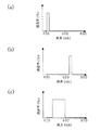
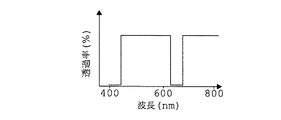
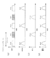
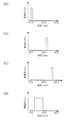
図1は本発明の実施例1にかかる内視鏡装置の全体の構成を示すブロック図、図2は実施例1の内視鏡装置に用いる励起波長選択フィルターの構成図、図3は実施例1の内視鏡装置に用いる励起波長選択フィルターの分光透過率特性を示すグラフであり、(a)は第1の励起波長選択フィルター7-Ex1の分光透過率特性、(b)は第2の励起波長選択フィルター7-Ex2の分光透過率特性、(c)は可視光フィルター7-Visの分光透過率特性を夫々示している。図4は実施例1の内視鏡装置に用いる対物光学系内に配置した励起波長遮断フィルターの分光透過率特性を示すグラフ、図5は実施例1の内視鏡装置に用いる励起光と蛍光の波長特性の関係を模式的に示したグラフである。図6は実施例1の内視鏡装置におけるスクリーニングモードでの画像取得のための光のタイミングを示すグラフであり、(a)は光源装置1から発する光、(b)は生体12で反射する反射光、(c)は蛍光、(d)は撮像素子に入射する光を夫々示している。図7は実施例1の内視鏡装置における精査モードでの画像取得のための光のタイミングを示すグラフであり、(a)は光源装置1から発する光、(b)は生体12で反射する反射光、(c)は蛍光、(d)は撮像素子に入射する光を夫々示している。
Next, an embodiment of the endoscope apparatus of the present invention will be described.
FIG. 1 is a block diagram showing the overall configuration of an endoscope apparatus according to
実施例1の内視鏡装置は、光源部としての光源装置1と、スコープ本体2と、プロセッサ3と、モニタ装置4からなる。
光源装置1は、可視光帯域から近赤外波長帯域を含む光を放射するランプ8と、励起波長選択手段としての励起波長選択フィルター7と、コンデンサレンズ9を有し、複数の波長の励起光を時系列で発するように構成されている。
スコープ本体2は、ライトガイドファイバ10と、照明レンズ11と、撮像光学系としての対物光学系13と、撮像素子5を有している。対物光学系13は、内部に光源装置1から出射され生体12で反射されることによって入射した励起光を遮断する励起波長遮断フィルター6を有している。
そして、光源装置1と、ライトガイドファイバ10と、照明レンズ11とが、本発明の励起光供給部を構成し、対物光学系13と、撮像素子5とが、本発明の蛍光検出部を構成している。
プロセッサ3は、励起波長選択フィルター7による励起波長の選択の切替と画像取得のタイミングを制御して画像処理を行うように構成されている。
モニタ装置4は、プロセッサ3を介して画像処理された画像を表示するように構成されている。
The endoscope apparatus according to the first embodiment includes a
The
The scope body 2 includes a
The
The processor 3 is configured to perform image processing by controlling switching of excitation wavelength selection by the excitation
The
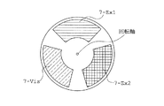
励起波長選択フィルター7は、図2に示すように、遮光性の円板の周方向に設けられた3つの開口に、それぞれ分光透過率特性の異なるフィルター7-Ex1、7-Ex2、7-Visを配置して構成されており、図1に示したモーター7’の駆動により回転軸を中心に回転して、フィルター7-Ex1、7-Ex2、7-Visのうち所望のフィルターが光路上にセットされることにより所定波長の光を選択的に透過させることが出来るようになっている。
励起波長選択フィルター7上のフィルター、7-Ex1、7-Ex2、7-Visの分光透過率特性は、図3(a)、(b)、(c)のようになっており、いずれかの波長領域の光を透過する。
第1の励起波長選択フィルター7-Ex1は、生体由来の自家蛍光を発するコラーゲンを励起させるため、図3(a)に示すように、400nm近傍の波長を透過させる透過率特性を有している。第2の励起波長選択フィルター7-Ex2は、近赤外で蛍光を発する蛍光薬剤であるAlexa680を励起させるため、図3(b)に示すように、680nm近傍の波長を透過させる透過率特性を有している。可視光フィルター7-Visは、生体からの反射光から生体の形態情報を取得し蛍光情報へ反映させるため、図3(c)に示すように、可視領域の400nm近傍から600nm近傍までの波長を透過させる透過率特性を有している。
なお、蛍光薬剤Alexa680は、腫瘍親和性を有するようなプローブ化を行い、予め生体へ投与させている。
As shown in FIG. 2, the excitation
The spectral transmittance characteristics of the filters on the excitation
The first excitation wavelength selection filter 7-Ex1 has a transmittance characteristic that transmits a wavelength in the vicinity of 400 nm as shown in FIG. 3A in order to excite collagen that emits autofluorescence derived from a living body. . The second excitation wavelength selection filter 7-Ex2 excites Alexa680, which is a fluorescent agent that fluoresces in the near infrared, so that it has a transmission characteristic that transmits wavelengths near 680 nm as shown in FIG. 3 (b). Have. The visible light filter 7-Vis obtains the morphological information of the living body from the reflected light from the living body and reflects it in the fluorescence information. As shown in FIG. 3 (c), the visible light filter 7-Vis changes the wavelength from 400 nm to 600 nm in the visible region. It has a transmittance characteristic to transmit.
Note that the fluorescent agent Alexa 680 is probed so as to have tumor affinity and is administered to a living body in advance.
ランプ8から出射した光は、励起波長選択フィルター7を介して所望の励起波長の光成分のみが抽出され、コンデンサレンズ9を経てスコープ本体2の図示省略したライトガイドコネクタに供給された後、ライトガイドファイバ10によって伝送され、挿入部の先端部(即ち、スコープ本体2の先端)に固定された先端面の照明窓に取り付けた照明レンズ11を経て、体腔内の被検査体12側に出射し、被検査体12を選択した波長帯域で照明、励起する。
図5は第1の励起光Ex1と、第1の励起光Ex1により励起されたコラーゲンによる蛍光Flu1と、第2の励起光Ex2と、第2の励起光Ex2により励起されたAlexa680による蛍光Flu2、のそれぞれの波長領域を示すグラフである。なお、図18には400nm近傍で励起した、主にコラーゲン由来の自家蛍光スペクトルを示してある。
From the light emitted from the lamp 8, only a light component having a desired excitation wavelength is extracted through the excitation
FIG. 5 shows the first excitation light Ex1, the fluorescence Flu1 due to collagen excited by the first excitation light Ex1, the second excitation light Ex2, and the fluorescence Flu2 due to Alexa 680 excited by the second excitation light Ex2. It is a graph which shows each wavelength range of these. FIG. 18 shows an autofluorescence spectrum mainly derived from collagen excited at around 400 nm.
内視鏡の先端部(即ち、スコープ本体2の先端)には、照明窓に隣接して観察窓が設けられている。対物レンズ13は、この観察窓に取り付けられており、照明された被検査体12側からの反射光及び蛍光が入射され、撮像素子5に像を結ぶ。励起波長遮断フィルター6は、対物光学系13内に配置されており、入射光から励起光の波長成分を遮断する。なお、励起波長遮断フィルター6は、1枚で構成しても、図1に示したように複数枚で構成してもよい。
An observation window is provided adjacent to the illumination window at the distal end of the endoscope (ie, the distal end of the scope main body 2). The
励起波長遮断フィルター6は、図4に示すように、励起波長選択フィルター7-Ex1、7-Ex2の透過波長帯域を遮断し、可視領域を含みコラーゲンの蛍光とAlexa680の蛍光を透過させる特性を有している。この2つの励起光の波長領域では、十分な遮光を行うために透過特性としてOD4以上が必要であり、このため100層から200層程度の多層膜フィルターで構成する必要がある。なお、コラーゲンの蛍光波長と可視波長の一部が重なるため、図4に示した励起波長遮断フィルター6の特性で可視光の生体12からの反射光も取得することが出来る。
なお、100層以上の成膜は、近年装置の飛躍的な進歩を遂げたイオン成膜方法やスパッタ方法で可能となっている。
従って、この励起波長遮断フィルター6により各々波長の異なる複数の励起光を遮断し、波長の異なるコラーゲン由来の蛍光成分と蛍光薬剤Alexa680の蛍光成分のみを透過し、撮像素子5へ結像することができる。また、この励起波長遮断フィルター6は可視領域の一部も透過する特性としているため、生体の形態情報を含む可視反射光も取得できる。
As shown in FIG. 4, the excitation wavelength blocking filter 6 has a characteristic of blocking the transmission wavelength band of the excitation wavelength selection filters 7-Ex1 and 7-Ex2 and transmitting the fluorescence of collagen and the fluorescence of Alexa680 including the visible region. is doing. In these two excitation light wavelength regions, OD4 or more is required as a transmission characteristic in order to perform sufficient light shielding. For this reason, it is necessary to form a multilayer filter of about 100 to 200 layers. In addition, since the fluorescence wavelength of collagen and a part of visible wavelength overlap, the reflected light from the living
In addition, the film formation of 100 layers or more is possible by the ion film formation method and the sputtering method which have achieved dramatic progress in recent years.
Therefore, the excitation wavelength blocking filter 6 blocks a plurality of excitation lights each having a different wavelength, transmits only the fluorescent component derived from collagen having a different wavelength and the fluorescent component of the fluorescent agent Alexa 680, and forms an image on the image sensor 5. it can. In addition, since the excitation wavelength blocking filter 6 has a characteristic of transmitting part of the visible region, visible reflected light including morphological information of the living body can be acquired.
撮像素子5で受光した信号は、信号線を介してプロセッサ3に入力される。プロセッサ3は、撮像素子5の画像信号に対する増幅、ホワイトバランス等の前処理を行うプリプロセス回路15と、A/D変換回路16と、画像強調などの処理をする映像信号処理回路17と、D/A変換回路18と、フィルター制御回路14を備えている。
フィルター制御回路14は、励起波長選択フィルター7と、撮像素子5で撮像した蛍光または可視反射光を同期付けるように各フィルターの回転駆動を制御する。
映像信号処理回路17では、蛍光画像と可視画像の合成等の処理も行うように構成されており、病変部を認識しやすくし、術者(或いは診断者)に対し、より診断しやすい画像を提供できるようになっている。
D/A変換回路18から出力された映像信号は、モニタ4に入力される。そして、撮像素子5の撮像面に結像された蛍光像及び可視光像が、モニタ4の表示面に表示されるようになっている。
A signal received by the image sensor 5 is input to the processor 3 via a signal line. The processor 3 includes a
The
The video
The video signal output from the D /
通常、ビデオフォーマットのNTSCでは、フレームレートは30フレーム/秒である。ところが、生体からの可視領域の反射光強度と比較し、蛍光強度(自家蛍光、蛍光薬剤共)は10-3〜10-4と非常に微弱である。このため、フレームレートを少なくし、1フレーム当りの露光時間を長くすることで、S/Nを改善させる必要がある。ところが、3フレーム/秒等まで少なくなると、コマ送りのような画像となり、術者(或いは診断者)に負担を強いることになる。
複数の異なる蛍光を検出するには、その分、1フレーム当りの露光時間を多く取る必要があり、これによりフレームレートを小さくする必要が生じる。この改善のため、実施例1の内視鏡装置では以下の構成を取っている。図6及び図7は実施例1の内視鏡装置の画像取得のためのタイミングを示す特性図であり、図6はスクリーニングモード、図7は精査モードの二つのモードを示している。
まず、スクリーニングモードで、フレームレートを30〜10フレーム/秒とし、患部の疑いのある部位のおおよその絞込みを行う。次に、精査モードに切替え、フレームレートを上記スクリーニングモードと同等以下にし、スクリーニングモードで絞り込んだ注力部位の精査を行う。
このような手法により、術者(或いは診断者)の負担を軽減させることができる。
Usually, in the NTSC video format, the frame rate is 30 frames / second. However, compared with the reflected light intensity in the visible region from the living body, the fluorescence intensity (both autofluorescence and fluorescent agent) is very weak, 10 −3 to 10 −4 . For this reason, it is necessary to improve the S / N by reducing the frame rate and increasing the exposure time per frame. However, when the frame rate is reduced to 3 frames / second or the like, an image like frame advance is generated, which imposes a burden on an operator (or a diagnostician).
In order to detect a plurality of different fluorescences, it is necessary to increase the exposure time per frame accordingly, which necessitates a reduction in the frame rate. For this improvement, the endoscope apparatus according to the first embodiment has the following configuration. 6 and 7 are characteristic diagrams showing timing for image acquisition of the endoscope apparatus according to the first embodiment. FIG. 6 shows two modes of a screening mode and FIG. 7 shows a scrutiny mode.
First, in the screening mode, the frame rate is set to 30 to 10 frames / second, and an approximate narrowing down of the suspicious part of the affected part is performed. Next, the mode is switched to the scrutinization mode, the frame rate is set to be equal to or lower than that of the screening mode, and the focused area narrowed down in the screening mode is scrutinized.
By such a method, the burden on the operator (or the diagnostician) can be reduced.
図6に示すように、スクリーニングモードでは、励起波長選択フィルターの内、コラーゲンを励起する第一のフィルター7−Ex1と、可視光フィルター7−Visを用いて、図6(a)に示すように、順次、光源装置1から生体12へ照射する。このとき、生体12からは、図6(b)、図6(c)に示すように、生体12からの反射光と、コラーゲンからの自家蛍光が、時系列に出射される。従って、図6(d)に示すように、撮像素子5は、生体12からの反射光と、コラーゲンからの自家蛍光を時系列に取得できる。これにより、プロセッサ3を介して、形態画像(反射光)と、病変画像(蛍光)を構築することができる。
As shown in FIG. 6, in the screening mode, the first filter 7-Ex1 that excites collagen and the visible light filter 7-Vis among the excitation wavelength selection filters are used, as shown in FIG. 6 (a). Then, the living
次に、病変部抽出の感度、及び特異度をより向上させるために、図7に示すように、精査モードへと移行する。このモードでは、励起波長選択フィルターの内、コラーゲンを励起する第一のフィルター7−Ex1と、蛍光薬剤Alexa680を励起する第二のフィルター7−Ex2と、可視光フィルター7−Visを用いて、図7(a)に示すように、順次、光源装置1から生体12へ照射する。このとき、図7(b)、図7(c)に示すように、生体12からは、生体12からの反射光と、第1の蛍光であるコラーゲンからの自家蛍光と、第2の蛍光であるAlexa680からの蛍光が、時系列に出射される。従って、図7(d)に示すように、撮像素子5は、生体12からの反射光と、第1の蛍光であるコラーゲンからの自家蛍光と、第2の蛍光であるAlexa680からの蛍光を時系列に取得することができる。これにより、プロセッサ3を介して、形態画像(反射光)と、更に詳細な病変画像(蛍光)を構築でき、更なる診断能力の向上が図れる。
Next, in order to further improve the sensitivity and specificity of the lesion part extraction, as shown in FIG. In this mode, among the excitation wavelength selection filters, a first filter 7-Ex1 for exciting collagen, a second filter 7-Ex2 for exciting the fluorescent agent Alexa680, and a visible light filter 7-Vis are used. As shown to 7 (a), the
なお、胃のような粘膜が厚く励起光自体が吸収されることで蛍光強度が微弱となる部位とは異なり、食道のような粘膜が薄く比較的蛍光強度の強い部位では、精査モードのみでスクリーニングから精査までの検査も可能である。
また、励起波長選択フィルター7の構成としては、図8に示すように、スクリーニングモード用と精査モード用に、内周と外周に分離し、光路上に設置しても良い。このようにすれば、観察モード切替において、複雑な回転制御が不要となるため、回転駆動装置の簡略化が可能となる。
また、図9や図10に示すように、光源装置1において、ランプ8に加えて励起用光源として半導体レーザー(LD)等を用い、光路を切替え可能な構成(図9)や、2つの光を併用する構成(図10)としても良い。半導体レーザーでは、狭波長帯域で強度の出力を得られるため、微弱な蛍光である自家蛍光物質や色素を励起するには適している。なお、この場合、励起波長選択フィルターにおいて、図2に示す可視光フィルター7-Vis以外の領域は遮光するようにする。
Unlike the site where the mucous membrane such as the stomach is thick and the excitation light itself is absorbed, the fluorescence intensity is weak, and the thin mucosa such as the esophagus is screened in the examination mode only for the relatively strong fluorescence intensity. Inspection from scrutiny to scrutiny is also possible.
Moreover, as a structure of the excitation
Further, as shown in FIGS. 9 and 10, in the
このように構成された実施例1の内視鏡装置によれば、簡単な構成で、光源側で照射する波長を時系列に制御でき、異なる蛍光の発光タイミングを調整できる。また、これら複数の励起光の数と蛍光の検出数が等しくなるようにしたので、各々励起波長と蛍光波長との波長領域の間隔を適切に離すことにより、励起波長遮断フィルターを簡易的な特性とすることができ、自家蛍光と近赤外の蛍光色素と可視反射光の波長分離が可能となる。このため、励起用光源装置、励起波長遮断フィルターも簡易的な構造とすることができ、先端に撮像素子を配置したビデオ型の内視鏡において、複数の波長での励起ができ、且つ励起光と同数の蛍光を波長分離して検出する内視鏡装置を、比較的安価に実現できる。さらに、その結果、通常の可視観察の能力も備え、且つ、ガンの診断能のより一層の向上が可能な安価な先端ビデオ型の蛍光内視鏡装置が得られる。
なお、使用する蛍光薬剤の励起波長及び蛍光波長は、近赤外領域とすることが望ましい。可視領域では自家蛍光波長と重なり合うためにS/Nの劣化を招くので、それを防ぐためである。また、近赤外領域では生体下の光透過性が良いため粘膜下の深い領域の情報も得られるからである。
According to the endoscope apparatus of the first embodiment configured as described above, the wavelength irradiated on the light source side can be controlled in time series with a simple configuration, and the emission timing of different fluorescence can be adjusted. In addition, since the number of these excitation lights and the number of fluorescence detections are made equal, the excitation wavelength cutoff filter can be simplified in characteristics by appropriately separating the wavelength region between the excitation wavelength and the fluorescence wavelength. Thus, wavelength separation of autofluorescence, near-infrared fluorescent dye, and visible reflected light becomes possible. For this reason, the excitation light source device and the excitation wavelength cutoff filter can also have a simple structure, and in a video type endoscope in which an image sensor is arranged at the tip, excitation at a plurality of wavelengths is possible and excitation light Can be realized at a relatively low cost. Furthermore, as a result, an inexpensive advanced video-type fluorescence endoscope apparatus having normal visual observation capability and capable of further improving the diagnostic ability of cancer can be obtained.
In addition, it is desirable that the excitation wavelength and fluorescence wavelength of the fluorescent agent to be used be in the near infrared region. This is to prevent the S / N degradation because it overlaps with the autofluorescence wavelength in the visible region. Moreover, in the near-infrared region, information on a deep region under the mucous membrane can be obtained because the light transmittance under the living body is good.
次に、本発明の内視鏡装置の実施例2を説明する。
実施例2の内視鏡装置は、実施例1の内視鏡装置とは、励起波長選択フィルターの特性と励起波長遮断フィルターの特性のみが異なる。
図11は実施例2の内視鏡装置に用いる励起波長選択フィルターの分光透過率特性を示すグラフであり、(a)は第1の励起波長選択フィルター7-Ex1の分光透過率特性、(b)は第2の励起波長選択フィルター7-Ex2の分光透過率特性、(c)は可視光フィルター7-Visの分光透過率特性を夫々示している。
第1の励起波長選択フィルター7-Ex1は、近赤外で蛍光を発する蛍光薬剤であるAlexa680を励起させるため、図11(a)に示すように、680nm近傍の波長を透過させる透過率特性を有している。第2の励起光フィルター7-Ex2は、近赤外で蛍光を発する蛍光薬剤であるAlexa750を励起させるため、図11(b)に示すように、750nm近傍の波長を透過させる透過率特性を有している。可視光フィルター7-Visは、生体からの反射光から生体の形態情報を取得し蛍光情報へ反映させるため、図11(c)に示すように、可視領域の400nm近傍から600nm近傍までの波長を透過させる透過率特性を有している。
Next, a second embodiment of the endoscope apparatus of the present invention will be described.
The endoscope apparatus according to the second embodiment is different from the endoscope apparatus according to the first embodiment only in the characteristics of the excitation wavelength selection filter and the excitation wavelength cutoff filter.
FIG. 11 is a graph showing the spectral transmittance characteristics of the excitation wavelength selection filter used in the endoscope apparatus of Example 2, where (a) is the spectral transmittance characteristics of the first excitation wavelength selection filter 7-Ex1, and (b) ) Shows the spectral transmittance characteristic of the second excitation wavelength selective filter 7-Ex2, and (c) shows the spectral transmittance characteristic of the visible light filter 7-Vis.
The first excitation wavelength selection filter 7-Ex1 has a transmittance characteristic that transmits a wavelength in the vicinity of 680 nm as shown in FIG. 11 (a) in order to excite Alexa680, which is a fluorescent agent that emits fluorescence in the near infrared. Have. Since the second excitation light filter 7-Ex2 excites the Alexa750, which is a fluorescent agent that emits fluorescence in the near infrared, as shown in FIG. 11 (b), it has a transmittance characteristic that transmits a wavelength around 750 nm. is doing. The visible light filter 7-Vis obtains the morphological information of the living body from the reflected light from the living body and reflects it in the fluorescence information. As shown in FIG. 11 (c), the visible light filter 7-Vis changes the wavelength from the vicinity of 400 nm to 600 nm in the visible region. It has a transmittance characteristic to transmit.
図12は実施例2の内視鏡装置に用いる対物光学系内に配置した励起波長遮断フィルターの分光透過率特性を示すグラフである。
励起波長遮断フィルター6は、図12に示すように、励起波長選択フィルター7-Ex1、7-Ex2の透過波長帯域を遮断し、Alexa680の蛍光とAlexa750の蛍光を透過させる特性を有している。なお、この2つの励起光の波長領域では、十分な遮光を行うために透過特性としてOD4以上が必要であり、このため100層から200層程度の多層膜フィルターで構成する必要がある。なお、励起波長遮断フィルター6は、600nm以下の波長も透過させる特性を有している。このため、図12に示した励起波長遮断フィルター6の特性で可視光の生体12からの反射光も取得することが出来る。
FIG. 12 is a graph showing the spectral transmittance characteristics of the excitation wavelength cutoff filter arranged in the objective optical system used in the endoscope apparatus of Example 2.
As shown in FIG. 12, the excitation wavelength blocking filter 6 has a characteristic of blocking the transmission wavelength bands of the excitation wavelength selection filters 7-Ex1 and 7-Ex2 and transmitting Alexa680 fluorescence and Alexa750 fluorescence. Note that, in these two excitation light wavelength regions, OD4 or more is required as a transmission characteristic in order to perform sufficient light shielding, and therefore, it is necessary to form a multilayer filter of about 100 to 200 layers. The excitation wavelength cutoff filter 6 has a characteristic of transmitting a wavelength of 600 nm or less. For this reason, the reflected light from the living
また、実施例2の内視鏡装置に用いる光源装置1としては、半導体レーザーを用いても良い。図11(a)、(b)で示すような広帯域で遮光するバンドパスフィルターを製作するには、200層相当以上の多層膜にする必要があり、製造が難しい。半導体レーザーを用いると、光源装置の製造を容易にすることが出来、高機能で且つ更なる安価な装置を提供することが出来る。なお、この場合、励起波長選択フィルター7において、図2に示した可視光フィルター7-Vis以外の領域は遮光するようにする。
実施例2の内視鏡装置によれば、腫瘍親和性を持たせた近赤外領域で蛍光を発する蛍光薬剤のみを用いることにより、生体粘膜下の深い領域からも複数のガンに関連する機能情報を取得することが出来る。
その他の構成及び作用効果は、実施例1の内視鏡装置とほぼ同じである。
Further, a semiconductor laser may be used as the
According to the endoscope apparatus of the second embodiment, by using only a fluorescent agent that emits fluorescence in the near-infrared region having tumor affinity, a function related to a plurality of cancers even from a deep region under the biological mucous membrane. Information can be acquired.
Other configurations and operational effects are substantially the same as those of the endoscope apparatus according to the first embodiment.
次に、本発明の内視鏡装置の実施例3を説明する。
実施例3の内視鏡装置は、実施例1や実施例2の内視鏡装置とは、検出する蛍光の数、励起波長選択フィルターの特性と数、及び励起波長遮断フィルターの特性のみが異なる。
図13は実施例3の内視鏡装置に用いる励起波長選択フィルターの分光透過率特性を示すグラフであり、(a)は第1の励起波長選択フィルター7-Ex1の分光透過率特性、(b)は第2の励起波長選択フィルター7-Ex2の分光透過率特性、(c)は第3の励起波長選択フィルター7-Ex3の分光透過率特性、(d)は可視光フィルター7-Visの分光透過率特性を夫々示している。
第1の励起波長選択フィルター7-Ex1は、生体由来の自家蛍光を発するコラーゲンを励起させるため、図13(a)に示すように、400nm近傍の波長を透過させる透過率特性を有している。第2の励起波長選択フィルター7-Ex2は、近赤外で蛍光を発する蛍光薬剤であるCy5.5を励起させるため、図13(b)に示すように、680nm近傍の波長を透過させる透過率特性を有している。第3の励起波長選択フィルター7-Ex3は、近赤外で蛍光を発する蛍光薬剤であるAlexaを励起させるため、図13(c)に示すように、750nm近傍の波長を透過させる透過率特性を有している。可視光フィルター7-Visは、生体からの反射光から生体の形態情報を取得し蛍光情報へ反映させるため、図13(d)に示すように、可視領域の400nm近傍から600nm近傍の波長を透過させる透過率特性を有している。
なお、蛍光薬剤Alexa680、Alexa750は、腫瘍親和性を有するようなプローブ化を行い、予め生体へ投与させている。
Next, a third embodiment of the endoscope apparatus of the present invention will be described.
The endoscope apparatus according to the third embodiment differs from the endoscope apparatuses according to the first and second embodiments only in the number of fluorescence to be detected, the characteristics and number of excitation wavelength selection filters, and the characteristics of the excitation wavelength cutoff filter. .
FIG. 13 is a graph showing the spectral transmittance characteristics of the excitation wavelength selection filter used in the endoscope apparatus of Example 3, wherein (a) is the spectral transmittance characteristics of the first excitation wavelength selection filter 7-Ex1, and (b) ) Is the spectral transmittance characteristic of the second excitation wavelength selective filter 7-Ex2, (c) is the spectral transmittance characteristic of the third excitation wavelength selective filter 7-Ex3, and (d) is the spectral transmittance characteristic of the visible light filter 7-Vis. The transmittance characteristics are shown.
The first excitation wavelength selection filter 7-Ex1 has a transmittance characteristic that transmits a wavelength in the vicinity of 400 nm as shown in FIG. 13 (a) in order to excite collagen that emits autofluorescence derived from a living body. . The second excitation wavelength selection filter 7-Ex2 excites Cy5.5, which is a fluorescent agent that emits fluorescence in the near infrared, and therefore transmits a wavelength around 680 nm as shown in FIG. 13 (b). It has characteristics. The third excitation wavelength selection filter 7-Ex3 excites Alexa, which is a fluorescent agent that fluoresces in the near infrared, and has a transmittance characteristic that transmits a wavelength near 750 nm as shown in FIG. 13 (c). Have. The visible light filter 7-Vis transmits wavelengths from around 400 nm to 600 nm in the visible region, as shown in FIG. 13 (d), in order to acquire the form information of the living body from the reflected light from the living body and reflect it in the fluorescence information. It has a transmittance characteristic.
Note that the fluorescent agents Alexa680 and Alexa750 are probed so as to have tumor affinity and are administered to the living body in advance.
図15は第1の励起光Ex1と、第1の励起光Ex1により励起されたコラーゲンによる蛍光Flu1と、第2の励起光Ex2と、第2の励起光Ex2により励起されたAlexa680による蛍光Flu2と、第3の励起光Ex3と、第3の励起光Ex3により励起されたAlexa750による蛍光Flu3と、のそれぞれの波長領域を示すグラフである。
図14は実施例3の内視鏡装置に用いる対物光学系内に配置した励起波長遮断フィルターの分光透過率特性を示すグラフである。
励起波長遮断フィルター6は、図14に示すように、励起波長選択フィルター7-Ex1、7-Ex2、7-Ex3の透過波長帯域を遮断し、生体由来のコラーゲンの自家蛍光と、Alexa680の蛍光と、Alexa750の蛍光を透過させる特性を有している。なお、この3つの励起光の波長領域では、十分な遮光を行うために透過特性としてOD4以上が必要であり、このため100層から200層程度の多層膜フィルターで構成する必要がある。なお、励起波長遮断フィルター6は、600nm以下の波長も透過させる特性を有している。このため、図14に示した励起波長遮断フィルター6の特性で可視光の生体12からの反射光も取得することが出来る。
FIG. 15 shows the first excitation light Ex1, the fluorescence Flu1 due to collagen excited by the first excitation light Ex1, the second excitation light Ex2, and the fluorescence Flu2 due to Alexa 680 excited by the second excitation light Ex2. FIG. 11 is a graph showing respective wavelength regions of the third excitation light Ex3 and the fluorescence Flu3 by
FIG. 14 is a graph showing the spectral transmittance characteristics of an excitation wavelength cutoff filter arranged in the objective optical system used in the endoscope apparatus of Example 3.
As shown in FIG. 14, the excitation wavelength blocking filter 6 blocks the transmission wavelength bands of the excitation wavelength selection filters 7-Ex1, 7-Ex2, and 7-Ex3, and the autofluorescence of collagen derived from a living body and the fluorescence of Alexa680. It has the property of transmitting the fluorescence of Alexa750. In these three excitation light wavelength regions, a transmission characteristic of OD4 or higher is necessary to sufficiently shield the light, and therefore, it is necessary to form a multilayer filter of about 100 to 200 layers. The excitation wavelength cutoff filter 6 has a characteristic of transmitting a wavelength of 600 nm or less. For this reason, the reflected light from the living
また、実施例3の内視鏡装置に用いる光源装置1としては、半導体レーザーを用いても良い。図13(a)〜(c)に示すような広帯域で遮光するバンドパスフィルターを製作するには、200層相当以上の多層膜にする必要があり、製造が難しい。半導体レーザーを用いると、光源装置の製造を容易にすることが出来、高機能で且つ更なる安価な装置を提供することが出来る。なお、この場合、励起波長選択フィルター7において、図2に示した可視光フィルター7-Vis以外の領域は遮光するようにする。
画像取得のタイミングについては、図示省略したが実施例1の内視鏡装置と同様の駆動を行う。実施例3の内視鏡装置においては、精査モードでは、3つの蛍光と1つの反射光を取得する。スクリーニングモードでは、1つの反射光と1つ又は2つの蛍光を取得する。その際、組合せは任意に選べる。
実施例3の内視鏡装置によれば、生体由来の自家蛍光と、腫瘍親和性を持たせた近赤外領域で蛍光を発する蛍光薬剤を用いることにより、より多くのガンに関連する機能情報を取得することが出来、ガンの診断能力の向上が図れる。
その他の構成及び作用効果は、実施例1の内視鏡装置とほぼ同じである。
なお、スクリーニングモードは、1つの反射光と3つの蛍光の様々な組合せがある。また、このように、励起波長選択フィルター7に設けるフィルターの種類は、図2に示したような3つに限られるものではなく、円板に搭載可能であれば何種類でも可能である。その場合には、これに対応する励起波長遮断フィルターを設ける。なお、光源装置1に用いる励起光源としては、一部又は全てを半導体レーザー等に置き換えても良い。
Further, a semiconductor laser may be used as the
As for the timing of image acquisition, although not shown in the figure, the same driving as that of the endoscope apparatus of the first embodiment is performed. In the endoscope apparatus according to the third embodiment, three fluorescent lights and one reflected light are acquired in the close examination mode. In the screening mode, one reflected light and one or two fluorescences are acquired. At that time, the combination can be arbitrarily selected.
According to the endoscope apparatus of Example 3, functional information related to more cancers by using a fluorescent agent that emits fluorescence in the near-infrared region with autologous fluorescence derived from a living body and tumor affinity. Can be acquired, and the diagnostic ability of cancer can be improved.
Other configurations and operational effects are substantially the same as those of the endoscope apparatus according to the first embodiment.
The screening mode includes various combinations of one reflected light and three fluorescences. As described above, the number of types of filters provided in the excitation
次に、本発明の内視鏡装置の実施例4を説明する。
実施例4の内視鏡装置は、実施例1〜3の内視鏡装置に用いる励起波長遮断フィルターに加え、図示しない蛍光を分離する蛍光波長選択フィルターとしてファブリペロー型エアギャップ可変式チューナブルフィルターを対物光学系内に配置して構成されている。このように構成された実施例4の内視鏡装置によれば、蛍光波長内で詳細に波長分離することが可能となり、ガンに関連する機能情報をより一層取得でき、ガンの診断能力の向上が図れる。
その他の構成及び作用効果は、実施例1の内視鏡装置とほぼ同じである。
Next, a fourth embodiment of the endoscope apparatus of the present invention will be described.
The endoscope apparatus according to the fourth embodiment is a Fabry-Perot type air gap variable tunable filter as a fluorescence wavelength selection filter for separating fluorescence (not shown) in addition to the excitation wavelength blocking filter used in the endoscope apparatuses according to the first to third embodiments. Are arranged in the objective optical system. According to the endoscope apparatus of the fourth embodiment configured in this way, it becomes possible to perform wavelength separation in detail within the fluorescence wavelength, and more function information related to the cancer can be acquired, improving the diagnostic ability of the cancer. Can be planned.
Other configurations and operational effects are substantially the same as those of the endoscope apparatus according to the first embodiment.
次に、本発明の内視鏡装置の実施例5を説明する。
実施例5の内視鏡装置は、実施例1〜4の内視鏡装置に用いる撮像素子5として、通常の白黒の撮像素子とは異なり、図示しない受光素子の直前にモザイク型フィルターを配置した撮像素子を用いている。このモザイク型フィルターは、各励起光を遮断する特性を有している。このように構成された実施例5の内視鏡装置によれば、光源側で複数の励起光を同時に照射しても、撮像素子が蛍光を分離検出可能となり、光源装置の簡略化が図ることができる。
その他の構成及び作用効果は、実施例1の内視鏡装置とほぼ同じである。
なお、使用する蛍光薬剤は、実施例1〜4の内視鏡装置に用いるものに限られず、他のAlexaや、Cyなど近赤外に吸収スペクトル及び蛍光スペクトルを有するものであればよい。
Next, a fifth embodiment of the endoscope apparatus of the present invention will be described.
Unlike the normal black and white image sensor, the endoscope apparatus of Example 5 arrange | positioned the mosaic type filter just before the light receiving element which is not shown as the image sensor 5 used for the endoscope apparatus of Examples 1-4. An image sensor is used. This mosaic filter has a characteristic of blocking each excitation light. According to the endoscope apparatus of the fifth embodiment configured as described above, the imaging element can separate and detect fluorescence even when a plurality of excitation lights are simultaneously irradiated on the light source side, and the light source apparatus can be simplified. Can do.
Other configurations and operational effects are substantially the same as those of the endoscope apparatus according to the first embodiment.
In addition, the fluorescent agent to be used is not limited to those used in the endoscope apparatuses of Examples 1 to 4, and may be any substance having an absorption spectrum and a fluorescence spectrum in the near infrared, such as other Alexa and Cy.
本発明の内視鏡装置は、例えば、早期ガンなどの変化の少ない病変を高確率且つ高精度に検出することが求められる医学、生物学の分野において有用である。 The endoscope apparatus of the present invention is useful in the fields of medicine and biology, for example, where it is required to detect lesions with little change such as early cancer with high probability and high accuracy.
1 光源装置
2 スコープ本体
3 プロセッサ
4 モニタ装置
5 撮像素子
6 励起波長遮断フィルター
7 励起波長選択フィルター
7’ モーター
8 ランプ
9 コンデンサレンズ
10 ライトガイドファイバ
11 照明レンズ
12 生体(被検査体)
13 対物光学系
14 フィルター制御回路
15 プリプロセス回路
16 A/D変換器
17 映像信号処理回路
18 D/A変換器
DESCRIPTION OF
13 Objective
Claims (12)
前記光源部が、波長領域の異なる複数の励起光を選択する励起波長選択手段を有するとともに、前記撮像光学系が、前記励起波長選択手段で選択された励起波長の光を遮断する励起波長遮断フィルターを有し、前記励起光供給部を介して照射される波長領域の異なる励起光の数と同じ数の波長領域の異なる蛍光を、前記蛍光検出部が検出するようにしたことを特徴とする内視鏡装置。 A light source unit that emits excitation light for exciting the fluorescent substance, an excitation light supply unit that irradiates the living body with light emitted from the light source unit, and an imaging optical system for imaging the fluorescence emitted from the living body In an endoscope apparatus having a fluorescence detection unit,
The light source unit has excitation wavelength selection means for selecting a plurality of excitation lights in different wavelength regions, and the imaging optical system blocks an excitation wavelength cutoff filter that blocks light of the excitation wavelength selected by the excitation wavelength selection means And the fluorescence detection unit detects fluorescence having the same number of wavelength regions as the number of excitation light beams having different wavelength regions irradiated through the excitation light supply unit. Endoscopic device.
Priority Applications (2)
| Application Number | Priority Date | Filing Date | Title |
|---|---|---|---|
| JP2005120895A JP2006296635A (en) | 2005-04-19 | 2005-04-19 | Endoscope apparatus |
| US11/405,554 US20060247537A1 (en) | 2005-04-19 | 2006-04-18 | Endoscope apparatus |
Applications Claiming Priority (1)
| Application Number | Priority Date | Filing Date | Title |
|---|---|---|---|
| JP2005120895A JP2006296635A (en) | 2005-04-19 | 2005-04-19 | Endoscope apparatus |
Publications (2)
| Publication Number | Publication Date |
|---|---|
| JP2006296635A true JP2006296635A (en) | 2006-11-02 |
| JP2006296635A5 JP2006296635A5 (en) | 2008-04-24 |
Family
ID=37235398
Family Applications (1)
| Application Number | Title | Priority Date | Filing Date |
|---|---|---|---|
| JP2005120895A Pending JP2006296635A (en) | 2005-04-19 | 2005-04-19 | Endoscope apparatus |
Country Status (2)
| Country | Link |
|---|---|
| US (1) | US20060247537A1 (en) |
| JP (1) | JP2006296635A (en) |
Cited By (17)
| Publication number | Priority date | Publication date | Assignee | Title |
|---|---|---|---|---|
| WO2008072444A1 (en) * | 2006-12-14 | 2008-06-19 | Olympus Corporation | Endoscope system |
| WO2008081897A1 (en) * | 2006-12-28 | 2008-07-10 | Olympus Corporation | Fluorescent endoscope system |
| JP2009145343A (en) * | 2007-12-11 | 2009-07-02 | Commissariat A L'energie Atomique | System of fluorescence analysis of field in illuminated area |
| JP2009300339A (en) * | 2008-06-17 | 2009-12-24 | Mitsuo Hashimoto | Nondestructive inspection device and nondestructive inspection method |
| JP2010172530A (en) * | 2009-01-30 | 2010-08-12 | Fujifilm Corp | Fluorescence endoscope system and fluorescence observing method |
| JP2011062408A (en) * | 2009-09-18 | 2011-03-31 | Fujifilm Corp | Fluorescent image imaging device |
| JP2011092683A (en) * | 2009-09-29 | 2011-05-12 | Fujifilm Corp | Electronic endoscope |
| JP2011188929A (en) * | 2010-03-12 | 2011-09-29 | Olympus Corp | Fluorescent endoscope apparatus |
| JP2011200534A (en) * | 2010-03-26 | 2011-10-13 | Fujifilm Corp | Electronic endoscope system and color imaging element |
| JP2013114233A (en) * | 2011-11-30 | 2013-06-10 | Olympus Corp | Image processing device, microscope system, image processing method and image processing program |
| JP2013255813A (en) * | 2013-07-17 | 2013-12-26 | Fujifilm Corp | Fluorescence image capturing device |
| WO2018225122A1 (en) * | 2017-06-05 | 2018-12-13 | オリンパス株式会社 | Endoscope device |
| JP2019510220A (en) * | 2016-03-14 | 2019-04-11 | マサチューセッツ インスティテュート オブ テクノロジー | Devices and methods for imaging shortwave infrared fluorescence |
| JP2019513229A (en) * | 2016-03-14 | 2019-05-23 | マサチューセッツ インスティテュート オブ テクノロジー | Device and method for imaging shortwave infrared fluorescence |
| US10667675B2 (en) | 2016-02-18 | 2020-06-02 | Panasonic Corporation | Imaging device and image processing method |
| JP2020157102A (en) * | 2015-11-27 | 2020-10-01 | 株式会社リコー | Pulse wave measurement device, pulse wave measurement program, pulse wave measurement method, and pulse wave measurement system |
| JP2021099355A (en) * | 2018-01-22 | 2021-07-01 | ヴェリリー ライフ サイエンシズ エルエルシー | High-throughput hyperspectral imaging system |
Families Citing this family (17)
| Publication number | Priority date | Publication date | Assignee | Title |
|---|---|---|---|---|
| US8498695B2 (en) | 2006-12-22 | 2013-07-30 | Novadaq Technologies Inc. | Imaging system with a single color image sensor for simultaneous fluorescence and color video endoscopy |
| JP4954858B2 (en) * | 2007-11-30 | 2012-06-20 | オリンパス株式会社 | Fluorescence observation apparatus and endoscope apparatus |
| US9072445B2 (en) * | 2008-01-24 | 2015-07-07 | Lifeguard Surgical Systems Inc. | Common bile duct surgical imaging system |
| MX2010010292A (en) | 2008-03-18 | 2011-01-25 | Novadaq Technologies Inc | Imaging system for combined full-color reflectance and near-infrared imaging. |
| US20240041388A1 (en) * | 2008-07-30 | 2024-02-08 | Vanderbilt University | System for facilitating differentiation between parathyroid tissue and thyroid tissue and applications of same |
| CN102333473A (en) * | 2009-03-24 | 2012-01-25 | 奥林巴斯医疗株式会社 | Fluorescence observation device |
| DE102009020252B4 (en) * | 2009-05-07 | 2012-01-12 | Krohne Optosens Gmbh | Device for measuring the fluorescence of a medium |
| JP5604248B2 (en) * | 2010-09-28 | 2014-10-08 | 富士フイルム株式会社 | Endoscopic image display device |
| JP6103824B2 (en) * | 2012-06-04 | 2017-03-29 | オリンパス株式会社 | Fluorescence endoscope device |
| JP6157135B2 (en) * | 2013-02-07 | 2017-07-05 | オリンパス株式会社 | Light source imaging device |
| WO2017047142A1 (en) * | 2015-09-18 | 2017-03-23 | オリンパス株式会社 | Endoscopic device and endoscopic system |
| WO2017079844A1 (en) | 2015-11-13 | 2017-05-18 | Novadaq Technologies Inc. | Systems and methods for illumination and imaging of a target |
| EP4155716A1 (en) * | 2016-01-26 | 2023-03-29 | Stryker European Operations Limited | Image sensor assembly |
| USD916294S1 (en) | 2016-04-28 | 2021-04-13 | Stryker European Operations Limited | Illumination and imaging device |
| CA3027592A1 (en) | 2016-06-14 | 2017-12-21 | John Josef Paul FENGLER | Methods and systems for adaptive imaging for low light signal enhancement in medical visualization |
| EP4242743A3 (en) | 2017-02-10 | 2023-10-18 | Stryker European Operations Limited | Open-field handheld fluorescence imaging systems and methods |
| JP6467746B1 (en) * | 2018-04-20 | 2019-02-13 | パナソニックIpマネジメント株式会社 | Endoscope system and method for operating endoscope system |
Citations (8)
| Publication number | Priority date | Publication date | Assignee | Title |
|---|---|---|---|---|
| JPH07155286A (en) * | 1993-12-03 | 1995-06-20 | Olympus Optical Co Ltd | Fluorescence observing apparatus |
| JPH07222712A (en) * | 1994-02-10 | 1995-08-22 | Olympus Optical Co Ltd | Fluorescent endoscope system |
| JP2001137172A (en) * | 1999-11-11 | 2001-05-22 | Fuji Photo Film Co Ltd | Fluorescence detection equipment |
| JP2004237081A (en) * | 2003-01-14 | 2004-08-26 | Morita Mfg Co Ltd | Diagnostic imaging apparatus |
| WO2004106896A2 (en) * | 2003-06-03 | 2004-12-09 | British Columbia Cancer Agency | Methods and apparatus for fluorescence imaging using multiple excitation-emission pairs and simultaneous multi-channel image detection |
| US20050027166A1 (en) * | 2003-06-17 | 2005-02-03 | Shinya Matsumoto | Endoscope system for fluorescent observation |
| JP2005087728A (en) * | 2003-08-08 | 2005-04-07 | Olympus Corp | Capsule type optical sensor |
| JP2005319115A (en) * | 2004-05-10 | 2005-11-17 | Pentax Corp | Fluorescent observation endoscope apparatus |
Family Cites Families (6)
| Publication number | Priority date | Publication date | Assignee | Title |
|---|---|---|---|---|
| US5769792A (en) * | 1991-07-03 | 1998-06-23 | Xillix Technologies Corp. | Endoscopic imaging system for diseased tissue |
| US20020138008A1 (en) * | 2000-01-13 | 2002-09-26 | Kazuhiro Tsujita | Method and apparatus for displaying fluorescence images and method and apparatus for acquiring endoscope images |
| US6468204B2 (en) * | 2000-05-25 | 2002-10-22 | Fuji Photo Film Co., Ltd. | Fluorescent endoscope apparatus |
| US6748259B1 (en) * | 2000-06-15 | 2004-06-08 | Spectros Corporation | Optical imaging of induced signals in vivo under ambient light conditions |
| US20030044353A1 (en) * | 2001-01-05 | 2003-03-06 | Ralph Weissleder | Activatable imaging probes |
| US7257437B2 (en) * | 2002-07-05 | 2007-08-14 | The Regents Of The University Of California | Autofluorescence detection and imaging of bladder cancer realized through a cystoscope |
-
2005
- 2005-04-19 JP JP2005120895A patent/JP2006296635A/en active Pending
-
2006
- 2006-04-18 US US11/405,554 patent/US20060247537A1/en not_active Abandoned
Patent Citations (8)
| Publication number | Priority date | Publication date | Assignee | Title |
|---|---|---|---|---|
| JPH07155286A (en) * | 1993-12-03 | 1995-06-20 | Olympus Optical Co Ltd | Fluorescence observing apparatus |
| JPH07222712A (en) * | 1994-02-10 | 1995-08-22 | Olympus Optical Co Ltd | Fluorescent endoscope system |
| JP2001137172A (en) * | 1999-11-11 | 2001-05-22 | Fuji Photo Film Co Ltd | Fluorescence detection equipment |
| JP2004237081A (en) * | 2003-01-14 | 2004-08-26 | Morita Mfg Co Ltd | Diagnostic imaging apparatus |
| WO2004106896A2 (en) * | 2003-06-03 | 2004-12-09 | British Columbia Cancer Agency | Methods and apparatus for fluorescence imaging using multiple excitation-emission pairs and simultaneous multi-channel image detection |
| US20050027166A1 (en) * | 2003-06-17 | 2005-02-03 | Shinya Matsumoto | Endoscope system for fluorescent observation |
| JP2005087728A (en) * | 2003-08-08 | 2005-04-07 | Olympus Corp | Capsule type optical sensor |
| JP2005319115A (en) * | 2004-05-10 | 2005-11-17 | Pentax Corp | Fluorescent observation endoscope apparatus |
Cited By (28)
| Publication number | Priority date | Publication date | Assignee | Title |
|---|---|---|---|---|
| JP2008148791A (en) * | 2006-12-14 | 2008-07-03 | Olympus Corp | Endoscope system |
| WO2008072444A1 (en) * | 2006-12-14 | 2008-06-19 | Olympus Corporation | Endoscope system |
| US8214025B2 (en) | 2006-12-28 | 2012-07-03 | Olympus Corporation | Fluorescence endoscope system |
| WO2008081897A1 (en) * | 2006-12-28 | 2008-07-10 | Olympus Corporation | Fluorescent endoscope system |
| JP2009145343A (en) * | 2007-12-11 | 2009-07-02 | Commissariat A L'energie Atomique | System of fluorescence analysis of field in illuminated area |
| US8598540B2 (en) | 2007-12-11 | 2013-12-03 | Commissariat A L'energie Atomique | System of fluorescence analysis of a field in an illuminated area |
| JP2009300339A (en) * | 2008-06-17 | 2009-12-24 | Mitsuo Hashimoto | Nondestructive inspection device and nondestructive inspection method |
| JP2010172530A (en) * | 2009-01-30 | 2010-08-12 | Fujifilm Corp | Fluorescence endoscope system and fluorescence observing method |
| JP2011062408A (en) * | 2009-09-18 | 2011-03-31 | Fujifilm Corp | Fluorescent image imaging device |
| US8767059B2 (en) | 2009-09-29 | 2014-07-01 | Fujifilm Corporation | Electronic endoscope |
| JP2011092683A (en) * | 2009-09-29 | 2011-05-12 | Fujifilm Corp | Electronic endoscope |
| JP2011188929A (en) * | 2010-03-12 | 2011-09-29 | Olympus Corp | Fluorescent endoscope apparatus |
| JP2011200534A (en) * | 2010-03-26 | 2011-10-13 | Fujifilm Corp | Electronic endoscope system and color imaging element |
| JP2013114233A (en) * | 2011-11-30 | 2013-06-10 | Olympus Corp | Image processing device, microscope system, image processing method and image processing program |
| US9632300B2 (en) | 2011-11-30 | 2017-04-25 | Olympus Corporation | Image processing apparatus, microscope system, image processing method, and computer-readable recording medium |
| JP2013255813A (en) * | 2013-07-17 | 2013-12-26 | Fujifilm Corp | Fluorescence image capturing device |
| JP2020157102A (en) * | 2015-11-27 | 2020-10-01 | 株式会社リコー | Pulse wave measurement device, pulse wave measurement program, pulse wave measurement method, and pulse wave measurement system |
| US10667675B2 (en) | 2016-02-18 | 2020-06-02 | Panasonic Corporation | Imaging device and image processing method |
| JP2019513229A (en) * | 2016-03-14 | 2019-05-23 | マサチューセッツ インスティテュート オブ テクノロジー | Device and method for imaging shortwave infrared fluorescence |
| JP2019510220A (en) * | 2016-03-14 | 2019-04-11 | マサチューセッツ インスティテュート オブ テクノロジー | Devices and methods for imaging shortwave infrared fluorescence |
| JP2022017366A (en) * | 2016-03-14 | 2022-01-25 | マサチューセッツ インスティテュート オブ テクノロジー | Device and method for imaging short wave infrared fluorescence |
| JP7146264B2 (en) | 2016-03-14 | 2022-10-04 | マサチューセッツ インスティテュート オブ テクノロジー | Devices and methods for imaging shortwave infrared fluorescence |
| WO2018225122A1 (en) * | 2017-06-05 | 2018-12-13 | オリンパス株式会社 | Endoscope device |
| US11457800B2 (en) | 2017-06-05 | 2022-10-04 | Olympus Corporation | Endoscope device |
| JP2021099355A (en) * | 2018-01-22 | 2021-07-01 | ヴェリリー ライフ サイエンシズ エルエルシー | High-throughput hyperspectral imaging system |
| US11327017B2 (en) | 2018-01-22 | 2022-05-10 | Verily Life Sciences Llc | High-throughput hyperspectral imaging systems |
| JP7068518B2 (en) | 2018-01-22 | 2022-05-16 | ヴェリリー ライフ サイエンシズ エルエルシー | High throughput hyperspectral imaging system |
| US11598725B2 (en) | 2018-01-22 | 2023-03-07 | Verily Life Sciences Llc | High-throughput hyperspectral imaging systems |
Also Published As
| Publication number | Publication date |
|---|---|
| US20060247537A1 (en) | 2006-11-02 |
Similar Documents
| Publication | Publication Date | Title |
|---|---|---|
| JP2006296635A (en) | Endoscope apparatus | |
| JP3962122B2 (en) | Endoscope device | |
| EP1669019B1 (en) | Fluorescence endoscopy device | |
| JP4855728B2 (en) | Illumination device and observation device | |
| JP4818753B2 (en) | Endoscope system | |
| JP5073579B2 (en) | Imaging device | |
| JP4585050B1 (en) | Fluorescence observation equipment | |
| WO2015156153A1 (en) | Fluorescence endoscopy system | |
| US20080007716A1 (en) | Raman scattering light observation apparatus and endoscope apparatus | |
| US20060052710A1 (en) | Endoscope apparatus and fluorescence detection method using endoscope apparatus | |
| JP4663258B2 (en) | Endoscope device | |
| JP2005006974A (en) | Endoscope system and signal processor | |
| JP6710151B2 (en) | Endoscope device and operating method of endoscope device | |
| JP2006061683A (en) | Endoscopic apparatus | |
| JP2006296635A5 (en) | ||
| US20150182106A1 (en) | Switching Between White Light Imaging And Excitation Light Imaging Leaving Last Video Frame Displayed | |
| JPH10325798A (en) | Microscope apparatus | |
| JP2006340796A (en) | Sentinel lymph node detection system | |
| JP4744279B2 (en) | Electronic endoscope device | |
| JP2008043383A (en) | Fluorescence observation endoscope instrument | |
| JP3654324B2 (en) | Fluorescence detection device | |
| JP5331394B2 (en) | Endoscope device | |
| JP4459709B2 (en) | Fluorescence observation endoscope device | |
| JP2004305382A (en) | Special light observation system | |
| US20180092519A1 (en) | Infrared fluorescence observation device |
Legal Events
| Date | Code | Title | Description |
|---|---|---|---|
| A521 | Request for written amendment filed |
Free format text: JAPANESE INTERMEDIATE CODE: A523 Effective date: 20080312 |
|
| A621 | Written request for application examination |
Free format text: JAPANESE INTERMEDIATE CODE: A621 Effective date: 20080312 |
|
| A977 | Report on retrieval |
Free format text: JAPANESE INTERMEDIATE CODE: A971007 Effective date: 20100916 |
|
| A131 | Notification of reasons for refusal |
Free format text: JAPANESE INTERMEDIATE CODE: A131 Effective date: 20101102 |
|
| A02 | Decision of refusal |
Free format text: JAPANESE INTERMEDIATE CODE: A02 Effective date: 20110301 |