JP2006292882A - Diaphragm driving mechanism and camera - Google Patents
Diaphragm driving mechanism and camera Download PDFInfo
- Publication number
- JP2006292882A JP2006292882A JP2005111027A JP2005111027A JP2006292882A JP 2006292882 A JP2006292882 A JP 2006292882A JP 2005111027 A JP2005111027 A JP 2005111027A JP 2005111027 A JP2005111027 A JP 2005111027A JP 2006292882 A JP2006292882 A JP 2006292882A
- Authority
- JP
- Japan
- Prior art keywords
- diaphragm
- cam plate
- piezoelectric substrate
- aperture
- drive mechanism
- Prior art date
- Legal status (The legal status is an assumption and is not a legal conclusion. Google has not performed a legal analysis and makes no representation as to the accuracy of the status listed.)
- Abandoned
Links
Images


Landscapes
- Diaphragms For Cameras (AREA)
Abstract
Description
本発明は、絞り駆動機構、及び、絞り駆動機構を備えるカメラに関する。 The present invention relates to an aperture driving mechanism and a camera including the aperture driving mechanism.
従来、カメラに備えられた絞り駆動機構では、複数枚の絞り羽根が重なり合って光が通過する開口を形成しており、この複数枚の絞り羽根がカム機構によって回動されて開口の径が増減される。このカム機構は、絞り羽根に形成された突起と、この突起が挿入されるカム溝が形成されたカムプレートとで構成されており、カムプレートが駆動手段によって回動されると突起がカム溝に沿って移動して絞り羽根を回動させる。 2. Description of the Related Art Conventionally, a diaphragm drive mechanism provided in a camera has an aperture through which a plurality of diaphragm blades overlap to allow light to pass therethrough, and the plurality of diaphragm blades are rotated by a cam mechanism to increase or decrease the diameter of the aperture. Is done. This cam mechanism is composed of a protrusion formed on the aperture blade and a cam plate in which a cam groove into which the protrusion is inserted is formed. When the cam plate is rotated by a driving means, the protrusion is a cam groove. To move the diaphragm blades.
ここで、駆動手段としては、超音波モータ等が公知となっている(例えば、特許文献1、2参照)。この超音波モータは電磁モータと比較すると小型ではあるが、光軸方向や開口の径方向へ突出してしまうので、その分だけ絞り駆動機構が大型化し、カメラが大型化するという問題があった。 Here, as the driving means, an ultrasonic motor or the like is known (for example, see Patent Documents 1 and 2). Although this ultrasonic motor is smaller than the electromagnetic motor, the ultrasonic motor protrudes in the optical axis direction and the radial direction of the opening. Therefore, there is a problem that the diaphragm driving mechanism is increased in size and the camera is increased in size.
ところで、圧電基板上に形成された交差指状電極に電圧を印加して圧電基板に弾性表面波を発生させ、圧電基板に圧接された移動子を移動させるという弾性表面波アクチュエータが考案されている(例えば、特許文献3、4参照)。この弾性表面波アクチュエータの占有スペースは、圧電基板の厚み、面積と移動子の長さの分だけであり、超音波モータと比較して小型である。そこで、本発明者は、絞り駆動機構の駆動源を弾性表面波アクチュエータとすることで、絞り駆動機構を小型化することに着目した。
本発明は上記事実を考慮してなされたものであり、絞り駆動機構、及び絞り駆動機構を備えるカメラを小型化することを目的とする。 The present invention has been made in view of the above-described facts, and an object thereof is to reduce the size of an aperture driving mechanism and a camera including the aperture driving mechanism.
請求項1に記載の絞り駆動機構は、光が通過する開口を形成し、回動して前記開口の径を増減する複数枚の絞り羽根と、前記開口回りに回動して前記絞り羽根を回動させるカムプレートと、前記カムプレートを回動させるカムプレート駆動手段と、を備える絞り駆動機構であって、前記カムプレート駆動手段は、前記カムプレートに設けられた移動子と、前記移動子に圧接した圧電基板と、前記圧電基板に設けられ、電圧を印加されて前記圧電基板に弾性表面波を発生させる交差指状電極と、を有することを特徴とする。 The aperture drive mechanism according to claim 1 is formed with an aperture through which light passes, and a plurality of aperture blades that rotate to increase or decrease the diameter of the aperture; A diaphragm driving mechanism comprising a cam plate for rotating and a cam plate driving means for rotating the cam plate, wherein the cam plate driving means includes a moving element provided on the cam plate, and the moving element And a cross-finger electrode provided on the piezoelectric substrate and applied with a voltage to generate a surface acoustic wave on the piezoelectric substrate.
請求項1に記載の絞り駆動機構では、複数枚の絞り羽根が、光が通過する開口を形成しており、カムプレートがカムプレート駆動手段によって開口回りに回動されると絞り羽根が回動されて開口の径が増減される。 In the diaphragm drive mechanism according to claim 1, the plurality of diaphragm blades form an opening through which light passes, and the diaphragm blade rotates when the cam plate is rotated around the opening by the cam plate driving means. As a result, the diameter of the opening is increased or decreased.
カムプレート駆動手段では、カムプレートに設けられた移動子に圧電基板が圧接し、この圧接基板に交差指状電極が設けられており、交差指状電極に電圧が印加されて圧電基板に弾性表面波が発生する。この弾性表面波によって移動子が移動されてカムプレートが回動し、絞り羽根が回動されて開口の径が増減される。 In the cam plate driving means, a piezoelectric substrate is pressed against a moving element provided on the cam plate, and a cross finger electrode is provided on the pressure contact substrate. A voltage is applied to the cross finger electrode so that an elastic surface is applied to the piezoelectric substrate. A wave is generated. The moving element is moved by the surface acoustic wave to rotate the cam plate, and the diaphragm blades are rotated to increase or decrease the diameter of the opening.
ここで、カムプレート駆動手段の占有スペースは、圧電基板の厚み、面積と移動子の長さの分だけあり、従来のカムプレートを回動させる駆動手段と比して光軸方向及び開口の径方向への拡がりが少なくなっている。これによって、従来と比して絞り駆動機構を小型化できる。 Here, the space occupied by the cam plate driving means is equal to the thickness and area of the piezoelectric substrate and the length of the moving element. Compared with the driving means for rotating the conventional cam plate, the optical axis direction and the diameter of the opening. There is less spread in the direction. As a result, the aperture driving mechanism can be reduced in size as compared with the prior art.
請求項2に記載の絞り駆動機構は、請求項1に記載の絞り駆動機構であって、前記移動子が前記カムプレートの外周縁部から前記開口の径方向へ突出し、前記圧電基板が前記カムプレートの外周縁部に沿って延在することを特徴とする。 A diaphragm drive mechanism according to a second aspect of the present invention is the diaphragm drive mechanism according to the first aspect, wherein the movable element projects from the outer peripheral edge of the cam plate in the radial direction of the opening, and the piezoelectric substrate is the cam It extends along the outer periphery of the plate.
請求項2に記載の絞り駆動機構のカムプレート駆動手段では、移動子が、カムプレートの外周縁部から開口の径方向へ突出し、カムプレートの外周縁部に沿って延在する圧電基板に圧接している。 In the cam plate driving means of the diaphragm driving mechanism according to claim 2, the moving element projects in a radial direction of the opening from the outer peripheral edge portion of the cam plate and press-contacts the piezoelectric substrate extending along the outer peripheral edge portion of the cam plate. is doing.
ここで、カムプレート駆動手段の占有スペースは、開口の径方向に対してはカムプレートの外周縁部の周囲の移動子の長さと圧電基板の厚み分だけであり、また、光軸方向に対しては圧電基板の幅分だけである。この圧電基板の幅は、交差指状電極を形成できるだけの幅があれば十分である。このため、従来のカムプレートを回動させる駆動機構と比して光軸方向への拡がりを低減でき、従来と比して絞り駆動機構を薄型化できる。 Here, the occupied space of the cam plate driving means is only the length of the moving element around the outer peripheral edge of the cam plate and the thickness of the piezoelectric substrate with respect to the radial direction of the opening, and with respect to the optical axis direction. This is only the width of the piezoelectric substrate. The width of the piezoelectric substrate is sufficient if it has a width that can form the interdigital electrodes. For this reason, it is possible to reduce the spread in the optical axis direction as compared with a conventional drive mechanism that rotates the cam plate, and it is possible to make the diaphragm drive mechanism thinner as compared with the conventional drive mechanism.
請求項3に記載の絞り駆動機構は、請求項1又は2に記載の絞り駆動機構であって、前記カムプレートの前記移動子が形成された面に設けられた磁石と、前記磁石に面して設けられた磁性体と、を有することを特徴とする。 A diaphragm drive mechanism according to a third aspect is the diaphragm drive mechanism according to the first or second aspect, wherein the magnet is provided on a surface of the cam plate on which the moving element is formed, and faces the magnet. And a magnetic body provided.
請求項3に記載の絞り駆動機構では、磁石が、カムプレートの移動子が形成された面に設けられ、この磁石に面して磁性体が設けられており、磁性体が磁石に磁気的に吸引されることで、移動子が圧電基板に圧接される。これによって、移動子を圧電基板に圧接するための機構を簡略化できる。 In the diaphragm drive mechanism according to the third aspect, the magnet is provided on the surface of the cam plate on which the moving element is formed, the magnetic body is provided facing the magnet, and the magnetic body is magnetically applied to the magnet. By being sucked, the moving element is pressed against the piezoelectric substrate. As a result, a mechanism for pressing the moving element against the piezoelectric substrate can be simplified.
請求項4に記載の絞り駆動機構は、請求項3に記載の絞り駆動機構であって、前記磁石の位置を検出する磁気センサと、前記磁気センサによって検出された前記磁石の位置に基づいて、前記開口の径を増減させる絞り制御手段と、を有することを特徴とする。 The diaphragm drive mechanism according to claim 4 is the diaphragm drive mechanism according to claim 3, based on a magnetic sensor that detects the position of the magnet, and a position of the magnet detected by the magnetic sensor, And a diaphragm control means for increasing or decreasing the diameter of the opening.
請求項4に記載の絞り駆動機構では、カムプレートに設けられた磁石の位置が、磁気センサによって検出され、絞り制御手段が、磁気センサによって検出された磁石の位置に基づいて、開口の径を増減させる。 In the diaphragm drive mechanism according to the fourth aspect, the position of the magnet provided on the cam plate is detected by the magnetic sensor, and the diaphragm control means adjusts the diameter of the opening based on the position of the magnet detected by the magnetic sensor. Increase or decrease.
このように、移動子を圧電基板に圧接させるために設けられた磁石が、カムプレートの回動位置を検出するための検出子を兼ねるように構成したことで、カムプレートの回動位置を検出するための機構の部品点数を低減でき、コストを低減できる。 As described above, the magnet provided to press the moving element against the piezoelectric substrate is also configured to serve as a detecting element for detecting the rotating position of the cam plate, thereby detecting the rotating position of the cam plate. It is possible to reduce the number of parts of the mechanism for achieving this, and to reduce the cost.
請求項5に記載の絞り駆動機構は、光が通過する開口を形成し、回動して前記開口の径を増減する複数枚の絞り羽根と、前記絞り羽根を回動させる絞り羽根駆動手段と、を備える絞り駆動機構であって、前記絞り羽根駆動手段は、前記絞り羽根に形成された移動子と、前記移動子に圧接した圧電基板と、前記圧電基板に形成され、電圧を印加されて前記圧電基板に弾性表面波を発生させる交差指状電極と、を有することを特徴とする。 The aperture driving mechanism according to claim 5 is formed with an aperture through which light passes, and a plurality of aperture blades that rotate to increase or decrease the diameter of the aperture, and aperture blade driving means that rotates the aperture blades The diaphragm blade drive means includes a moving element formed on the diaphragm blade, a piezoelectric substrate in pressure contact with the moving element, and formed on the piezoelectric substrate, to which a voltage is applied. And an interdigitated electrode for generating surface acoustic waves on the piezoelectric substrate.
請求項5に記載の絞り駆動機構では、複数枚の絞り羽根が、光が通過する開口を形成しており、この絞り羽根が、絞り羽根駆動手段によって回動されて開口の径が増減される。 In the diaphragm drive mechanism according to claim 5, the plurality of diaphragm blades form an opening through which light passes, and the diaphragm blades are rotated by the diaphragm blade driving means to increase or decrease the diameter of the opening. .
絞り羽根駆動手段では、絞り羽根に設けられた移動子に圧電基板が圧接し、この圧接基板に交差指状電極が設けられており、交差指状電極に電圧が印加されて圧電基板に弾性表面波が発生する。この弾性表面波によって移動子が移動されて絞り羽根が回動し、開口の径が増減される。 In the diaphragm blade driving means, a piezoelectric substrate is pressed against a moving element provided on the diaphragm blade, and a cross finger electrode is provided on the pressure contact substrate. A voltage is applied to the cross finger electrode so that an elastic surface is applied to the piezoelectric substrate. A wave is generated. The moving element is moved by the surface acoustic wave and the diaphragm blades are rotated to increase or decrease the diameter of the opening.
ここで、絞り羽根駆動手段の占有スペースは、圧電基板の厚み、面積と移動子の長さの分だけあり、従来の絞り羽根を回動させる駆動機構と比して光軸方向及び開口の径方向への拡がりが少なくなっている。これによって、従来と比して絞り駆動機構を小型化できる。 Here, the space occupied by the diaphragm blade drive means is the thickness of the piezoelectric substrate, the area, and the length of the mover, and the optical axis direction and the diameter of the opening are compared with the conventional drive mechanism for rotating the diaphragm blade. There is less spread in the direction. As a result, the aperture driving mechanism can be reduced in size as compared with the prior art.
請求項6に記載のカメラは、請求項1乃至5の何れか1項に記載の絞り駆動機構を備えることを特徴とする。 A camera according to a sixth aspect includes the aperture driving mechanism according to any one of the first to fifth aspects.
請求項6に記載のカメラでは、絞り駆動機構の光軸方向及び開口の径方向への拡がりが低減されているので、小型化が可能である。 In the camera according to the sixth aspect, since the expansion of the aperture driving mechanism in the optical axis direction and the radial direction of the opening is reduced, the size can be reduced.
本発明は、上記構成にしたので、絞り駆動機構、及び絞り駆動機構を備えるカメラを小型化できる。 Since the present invention is configured as described above, it is possible to reduce the size of the aperture driving mechanism and the camera including the aperture driving mechanism.
以下に図面を参照しながら本発明の実施形態を説明する。 Embodiments of the present invention will be described below with reference to the drawings.
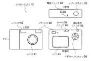
まず、図1を参照して、本実施形態に係るデジタルカメラ10の外観上の構成を説明する。図1に示すように、デジタルカメラ10は、カメラ本体11の正面に、被写体像を結像させるためのレンズ21、撮影時に必要に応じて被写体に照射する光を発するストロボ62、及び撮影する被写体の構図を決定するために用いられるファインダ88を備えている。また、デジタルカメラ10は、カメラ本体11の上面に、撮影を実行する際にユーザによって押圧操作されるレリーズボタン(所謂シャッター)92、及び電源スイッチ94を備えている。
First, an external configuration of the digital camera 10 according to the present embodiment will be described with reference to FIG. As shown in FIG. 1, a digital camera 10 includes a lens 21 for forming a subject image on the front of a
なお、本実施の形態に係るデジタルカメラ10のレリーズボタン92は、中間位置まで押下される状態(以下、「半押し状態S1」という。)と、当該中間位置を超えた最終押下位置まで押下される状態(以下、「全押し状態S2」という。)と、の2段階の押圧操作が検出可能に構成されている。そして、デジタルカメラ10では、レリーズボタン92を半押し状態S1にすることによりAE(Automatic Explosure、自動露出)機能が働いて露出状態(シャッタースピード、絞りの状態)が設定された後、AF(Auto Focus、自動合焦)機能が働いて合焦制御され、その後、引き続き全押し状態S2にすると露光(撮影)が行われるようになっている。 Note that the release button 92 of the digital camera 10 according to the present embodiment is pressed down to an intermediate position (hereinafter referred to as “half-pressed state S1”), and pressed to a final pressed position that exceeds the intermediate position. 2 states (hereinafter referred to as “fully pressed state S2”) can be detected. In the digital camera 10, after the release button 92 is half-pressed S1 to set the exposure state (shutter speed, aperture state) by operating the AE (Automatic Explosure) function, AF (Auto Focus (automatic focus) function is activated to control the focus, and then the exposure (photographing) is performed when the fully-pressed state S2 is subsequently entered.
一方、カメラ本体11の背面には、上記ファインダ88の接眼部が設けられている。このファインダ88の接眼部近傍(図1では下方)には、撮影によって得られたデジタル画像データにより示される被写体像や各種メニュー画面、そしてメッセージ等を表示するための液晶ディスプレイ(以下、「LCD」という。)44が設けられている。また、LCD44近傍(図1では上方)にはモード切替スイッチ96が設けられ、またLCD44近傍(図1では右方)には十字カーソルボタン98が設けられている。モード切替スイッチ96は、ユーザによってスライド操作によって、撮影を行うモードである撮影モード、及び撮影によって得られたデジタル画像データにより示される被写体像をLCD44に表示(再生)するモードである再生モードの何れか一方のモードに設定するためのものである。十字カーソルボタン98は、LCD44の表示領域における上・下・左・右の4方向の移動方向を示す4つの矢印キー及び当該4つの矢印キーの中央部に位置された決定キーの合計5つのキーを含んで構成されており、各キーの押圧により該当するコマンドを出力するものである。また、十字カーソルボタン98の近傍(図1では上方)には、ユーザの押圧操作によって、撮影時にストロボ62を強制的に発光させるモードである強制発光モードを設定するための強制発光スイッチ99が設けられている。
On the other hand, the eyepiece of the finder 88 is provided on the back of the
次に、図2を参照して、本実施の形態に係るデジタルカメラ10の電気系の構成を説明する。 Next, the configuration of the electrical system of the digital camera 10 according to the present embodiment will be described with reference to FIG.
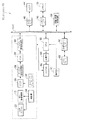
デジタルカメラ10は、レンズ21を含んで構成されたレンズユニット22を備えており、レンズユニット22の射出側でレンズ21の光軸後方には絞り駆動機構12、電荷結合素子(以下、「CCD」という。)24が設けられている。CCD24は、アナログ信号処理部26、アナログ/デジタル変換器(以下、「ADC」という。)28及びデジタル信号処理部30を介してシステムバスBUSに接続されている。アナログ信号処理部26は、CCDの出力信号に含まれるノイズ(特に熱雑音)等を軽減して正確な画素データを得る回路などを含んで構成されている。また、ADC28は、入力されたアナログ信号をデジタルデータに変換するためのものである。また、デジタル信号処理部30は、所定容量のラインバッファを内蔵し、かつ入力されたデジタル画像データをメモリ72の所定領域に直接記憶させる制御を行うと共に、デジタル画像データに対して各種のデジタル画像処理を行うものである。
The digital camera 10 includes a
なお、システムバスBUSには、デジタル信号処理部30,LCDインタフェース42,CPU(中央処理装置)50、メモリインタフェース70、外部メモリインタフェース80、及び圧縮・伸張処理回路86の各々が相互にデータやコマンドを授受可能に接続されている。LCDインタフェース42は、デジタル画像データにより示される画像やメニュー画面等をLCD44に表示させるための信号を生成してLCD44に供給するインタフェース回路である。CPU(中央処理装置)50は、デジタルカメラ10全体の動作を司る処理装置である。メモリ72は、主として撮影により得られたデジタル画像データを記憶するVRAM(Video RAM)により構成されたメモリである。メモリインタフェース70は、メモリ72に対するアクセスのための制御回路である。外部メモリインタフェース80は、スマートメディア(Smart Media(登録商標))等の記録メディアにより構成されたメモリカード82をデジタルカメラ10でアクセス可能とするためのインタフェース回路である。圧縮・伸張処理回路86は、所定の圧縮形式でデジタル画像データに対して圧縮処理を施す一方、圧縮処理されたデジタル画像データに対して圧縮形式に応じた伸張処理を施す処理回路である。
Note that the digital signal processing unit 30, the
従って、CPU50は、デジタル信号処理部30及び圧縮・伸張処理回路86の作動の制御、LCD44に対するLCDインタフェース42を介した各種情報の表示、メモリ72及びメモリカード82へのメモリインタフェース70及び外部メモリインタフェース80を介したアクセスを行う。
Therefore, the
一方、デジタルカメラ10には、主としてCCD24を駆動させるためのタイミング信号を生成してCCD24に供給するタイミングジェネレータ32が備えられており、CCD24の駆動はCPU50によりタイミングジェネレータ32を介して制御される。
On the other hand, the digital camera 10 includes a
また、デジタルカメラ10は駆動部34を備えており、レンズユニット22に備えられた焦点調整機構(詳細は後述)やズーム機構及び絞り駆動機構12の駆動もCPU50により駆動部34を介して制御される。
The digital camera 10 also includes a
CPU50は、光学ズーム倍率を変更する際には図示しないズーム機構を駆動制御してレンズユニット22に含まれるレンズ21の焦点距離を変化させる。また、CPU50は、CCD24による撮像によって得られた画像のコントラスト値が最大となるように上記焦点調整機構(後述)を駆動制御することによって合焦制御する。本実施の形態に係るデジタルカメラ10では、合焦制御として、読み取られた画像のコントラストが最大となるようにレンズの位置を設定する、所謂TTL(Through The Lens)方式を採用している。
When changing the optical zoom magnification, the
また、レリーズボタン92、電源スイッチ94、モード切替スイッチ96、十字カーソルボタン98、及び強制発光スイッチ99の各種ボタン類及びスイッチ類(同図では、「操作部90」と総称。)はCPU50に接続されており、CPU50は、これらの操作部90に対する操作状態を常時把握できる。
Further, the release button 92, the power switch 94, the mode change switch 96, the cross cursor button 98, and various buttons and switches (generally referred to as “
また、デジタルカメラ10は、ストロボ62とCPU50との間に介在され、CPU50の制御によりストロボ62を発光させるための電力を充電する充電部60を備えている。ストロボ62はCPU50にも接続されており、ストロボ62の発光はCPU50によって制御される。
In addition, the digital camera 10 includes a charging
次に、本実施の形態に係るデジタルカメラ10の全体的な動作について簡単に説明する。 Next, the overall operation of the digital camera 10 according to the present embodiment will be briefly described.
まず、CCD24によりレンズユニット22を介した撮像を行い、被写体像を示すR(赤)、G(緑)、B(青)の信号をアナログ信号処理部26に順次出力する。アナログ信号処理部26は、CCD24から入力された信号に対して相関二重サンプリング処理等のアナログ信号処理を施した後にADC28に順次出力する。ADC28は、アナログ信号処理部26から入力されたR,G,Bの信号を各々12ビットのR,G,Bの信号(デジタル画像データ)に変換してデジタル信号処理部30に順次出力する。デジタル信号処理部30は、内蔵しているラインバッファにADC28から順次出力されるデジタル画像データを蓄積して一旦メモリ72の所定領域に格納する。
First, an image is picked up by the
メモリ72の所定領域に格納されたデジタル画像データは、CPU50による制御によりデジタル信号処理部30によって読み出され、これらに所定の物理量に応じたデジタルゲインをかけることでホワイトバランス調整を行なうと共に、ガンマ処理及びシャープネス処理を行なって8ビットのデジタル画像データを生成し、更にYC信号処理を施して輝度信号Yとクロマ信号Cr,Cb(以下、「YC信号」という。)を生成し、YC信号をメモリ72の上記所定領域とは異なる領域に格納する。
Digital image data stored in a predetermined area of the
なお、LCD44は、CCD24による連続的な撮像によって得られた動画像(スルー画像)を表示してファインダとして使用することができるものとして構成されているが、このようにLCD44をファインダとして使用する場合には、生成したYC信号を、LCDインタフェース42を介して順次LCD44に出力する。これによってLCD44にスルー画像が表示されることになる。
The
ここで、レリーズボタン92がユーザによって半押し状態とされた場合、前述のようにAE機能が働いて露出状態が設定された後、AF機能が働いて合焦制御され、その後、引き続き全押し状態とされた場合、この時点でメモリ72に格納されているYC信号を、圧縮・伸張処理回路86によって所定の圧縮形式(本実施の形態ではJPEG形式)で圧縮した後に外部メモリインタフェース80を介してメモリカード82に記録することにより撮影が行われる。
Here, when the release button 92 is half-pressed by the user, after the AE function is activated and the exposure state is set as described above, the AF function is activated and focus control is performed, and then the fully-pressed state is continued. In this case, the YC signal stored in the
次に、絞り駆動機構12の構造について説明する。
[第1実施形態]
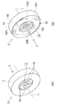
図3乃至図5に示すように、絞り駆動機構12は、絞りケース14と、5枚の絞り羽根16と、カムプレート18と、弾性表面波アクチュエータ20と、を備える。絞りケース14は、底付きの円筒体で、底面14Aには、円状の開口14Bが穿設され、5本のピン14Cが開口14Bの周囲に約72度の間隔で立設されている。また、絞り羽根16の基端部には、ピン14Cが挿入される支持孔16Aが形成されており、絞り羽根16が、絞りケース14にピン14C回りに回動自在に支持されている。また、5枚の絞り羽根16の自由端部は、開口14Bの周方向に順に重なり合って開口13を形成している。
Next, the structure of the
[First Embodiment]
As shown in FIGS. 3 to 5, the
また、カムプレート18は、絞りケース14に回動可能に支持され、絞り羽根16を間に置いて底面14Aに対向した円板である。また、カムプレート18の中央部には円状の開口18Aが穿設されている。また、絞り羽根16には、カムプレート18側に突出するカムフォロアピン16Bが立設されており、カムプレート18には、カムフォロアピン16Bが摺動する非貫通孔であるカム溝18Bが形成されている。このカム溝18Bは、周方向に延びており、図中時計回り方向へかけて外周側から内周側へ屈折している。
The
また、弾性表面波アクチュエータ20は、カムプレート18に立設された2本のピン18Cと、圧電基板40と、圧電基板40上に蒸着された交差指状電極42A、42Bと、を備える。2本のピン18Cは、カムプレート18のカム溝18Bが形成された面の裏面に、約180度の間隔で立設されている。圧電基板40は、ニオブ酸リチウムで形成された円状の板で、絞りケース14に回動不能に支持されてピン18Cに圧接されている。また、圧電基板40の中央部には円状の開口40Aが穿設されている。
The surface
また、圧電基板40上には、ピン18Cが圧接する圧接地点を間に置いて開口40Aの接線方向に対向する交差指状電極42A、42Bが形成されており、この交差指状電極42A、42Bにはそれぞれ、高周波電源(図示省略)が接続されている。図6(A)に示すように、交差指状電極42Aに高周波電圧が印加されると、交差指状電極42Aが励振し、圧電基板40に交差指状電極42B側へ進行する弾性表面波Hが発生する。この弾性表面波Hは、進行方向に対して後方楕円運動をしながら進行するので、圧電基板40に圧接されているピン18Cは、弾性表面波Hの進行方向と逆方向(図中矢印A方向)へ移動する。これによって、図6(B)に示すように、カムプレート18が図中時計回り方向に回転し、カムフォロアピン16Bがカム溝18Bに沿って外周側へ移動し、そして、図6(C)に示すように、絞り羽根16が外周側へ回動して開口13の径が増大する。
Further, on the
一方、図7(A)に示すように、交差指状電極42Bに高周波電圧が印加されると、交差指状電極42Bが励振し、圧電基板40に交差指状電極42A側へ進行する弾性表面波Hが発生する。そして、圧電基板40に圧接されているピン18Cは、弾性表面波Hの進行方向と逆方向(図中矢印B方向)へ移動する。これによって、図7(B)に示すように、カムプレート18が図中反時計回り方向に回転し、カムフォロアピン16Bがカム溝18Bに沿って内周側へ移動し、そして、図7(C)に示すように、絞り羽根16が内周側へ回動して開口13の径が減少する。
On the other hand, as shown in FIG. 7A, when a high-frequency voltage is applied to the
ここで、弾性表面波アクチュエータ20の占有スペースは、圧電基板40の厚み、面積とピン18Cの長さ分だけあり、従来のカムプレートを回動させる駆動機構と比して光軸L方向及び開口13の径方向への拡がりが少なくなっている。これによって、従来と比して絞り駆動機構12を小型化できる。
[第2実施形態]
次に、絞り駆動機構の第2実施形態について説明する。なお、第1実施形態と同様の構成には同一の符号を付し、説明は省略する。
Here, the space occupied by the surface
[Second Embodiment]
Next, a second embodiment of the aperture driving mechanism will be described. In addition, the same code | symbol is attached | subjected to the structure similar to 1st Embodiment, and description is abbreviate | omitted.
図8乃至図10に示すように、絞り駆動機構52は、絞りケース15と、5枚の絞り羽根16と、カムプレート54と、弾性表面波アクチュエータ56と、を備える。絞りケース15は、底付きの円筒体で、底面15Aには、円状の開口15Bが穿設され、5本のピン15Cが開口15Bの周囲に約72度の間隔で立設されており、このピン15Cが支持羽根16に形成された支持孔16Aに挿入されて、絞り羽根16が、絞りケース15にピン15C回りに回動自在に支持されている。カムプレート54は、絞りケース15に回動可能に支持され、絞り羽根16を間に置いて底面15Aに対向した円板である。また、カムプレート54の中央部には円状の開口54Aが穿設されている。また、カムプレート54には、カムフォロアピン16Bが摺動する非貫通孔であるカム溝54Bが形成されている。このカム溝54Bは、周方向に延びており、図中時計回り方向へかけて外周側から内周側へ屈折している。
As shown in FIGS. 8 to 10, the
また、弾性表面波アクチュエータ56は、圧電基板58と、圧電基板58上に蒸着された交差指状電極42A、42B、カムプレート54に立設された2本のピン54Cと、を備える。圧電基板58は、ニオブ酸リチウムで形成された細長い板材で、絞りケース14の内周面に固定されてカムプレート18の外周縁部に沿って延在している。また、2本のピン54Cは、カムプレート54の外周縁部に約180度の間隔で立設されており、開口54Aの径方向へ突出して圧電基板58に圧接している。
The surface
また、圧電基板58上には、ピン54Cが圧接する圧接地点を間に置いてカムプレート54の周方向に対向する交差指状電極42A、42Bが形成されており、この交差指状電極42A、42Bにはそれぞれ、高周波電源(図示省略)が接続されている。図11(A)に示すように、交差指状電極42Aに高周波電圧が印加されると、交差指状電極42Aが励振し、圧電基板58に交差指状電極42B側へ進行する弾性表面波Hが発生する。この弾性表面波Hは、進行方向に対して後方楕円運動をしながら進行するので、圧電基板58に圧接されているピン54Cは、弾性表面波Hの進行方向と逆方向(図中矢印A方向)へ移動する。これによって、図11(B)に示すように、カムプレート54が図中時計回り方向に回転し、カムフォロアピン16Bがカム溝18Bに沿って外周側へ移動し、そして、図11(C)に示すように、絞り羽根16が外周側へ回動して開口13の径が増大する。
On the
一方、図12(A)に示すように、交差指状電極42Bに高周波電圧が印加されると、交差指状電極42Bが励振し、圧電基板58に交差指状電極42A側へ進行する弾性表面波Hが発生する。そして、圧電基板58に圧接されているピン54Cは、弾性表面波Hの進行方向と逆方向(図中矢印B方向)へ移動する。これによって、図12(B)に示すように、カムプレート54が図中反時計回り方向に回転し、カムフォロアピン16Bがカム溝18Bに沿って内周側へ移動し、そして、図12(C)に示すように、絞り羽根16が内周側へ回動して開口13の径が減少する。
On the other hand, as shown in FIG. 12A, when a high-frequency voltage is applied to the
ここで、弾性表面波アクチュエータ56の占有スペースは、開口13の径方向に対してはピン54Cの長さと圧電基板58の厚みの分だけであり、また、光軸L方向に対しては圧電基板58の幅分だけである。この圧電基板58の幅は、交差指状電極42A、42Bを形成できるだけの幅があれば十分である。このため、従来のカムプレートを回動させる駆動機構と比して光軸L方向への拡がりを低減でき、従来と比して絞り駆動機構52を薄型化できる。
[第3実施形態]
次に、絞り駆動機構の第3実施形態について説明する。なお、第1、第2実施形態と同様の構成には同一の符号を付し、説明は省略する。
Here, the space occupied by the surface
[Third Embodiment]
Next, a third embodiment of the aperture driving mechanism will be described. In addition, the same code | symbol is attached | subjected to the structure similar to 1st, 2nd embodiment, and description is abbreviate | omitted.
図13乃至図15に示すように、絞り駆動機構62は、絞りケース17と、5枚の絞り羽根16と、カムプレート64と、支持板65と、弾性表面波アクチュエータ66と、を備える。絞りケース17は、底付きの円筒体で、底面17Aには、円状の開口17Bが穿設され、5本のピン17Cが開口17Bの周囲に約72度の間隔で立設されており、このピン17Cが支持羽根16に形成された支持孔16Aに挿入されて、絞り羽根16が、絞りケース17にピン17C回りに回動自在に支持されている。カムプレート64は、絞りケース17に回動不能に支持されて絞り羽根16を間に置いて底面17Aに対向した円板である。またカムプレート64の中央部には円状の開口64Aが穿設されている。また、カムプレート64には、カムフォロアピン16Bが摺動する貫通孔であるカム孔64Bが形成されている。このカム孔64Bは、周方向に延びており、図中時計回り方向へかけて外周側から内周側へ屈折している。また、支持板65は、絞りケース17に回動不能に支持されてカムプレート64に対向した円板である。また、支持板65の中央部には開口65Aが形成されている。
As shown in FIGS. 13 to 15, the
また、弾性表面波アクチュエータ66は、5枚の圧電基板68と、各圧電基板68上に蒸着された交差指状電極42A、42B、絞り羽根16に立設された2本のカムフォロアピン16Bと、を備える。各圧電基板68は、ニオブ酸リチウムで形成された板材で、支持板65に固定されて各カムフォロアピン16Bに圧接されている。
The surface
また、圧電基板68上には、カムフォロアピン16Bが圧接する圧接地点を間に置いて開口65Aの周方向に対向する交差指状電極42A、42Bが形成されており、この交差指状電極42A、42Bにはそれぞれ、高周波電源(図示省略)が接続されている。図16(A)に示すように、交差指状電極42Aに高周波電圧が印加されると、交差指状電極42Aが励振し、圧電基板68に交差指状電極42B側へ進行する弾性表面波Hが発生する。この弾性表面波Hは、進行方向に対して後方楕円運動をしながら進行するので、圧電基板68に圧接されているカムフォロアピン16Bは、弾性表面波Hの進行方向と逆方向(図中矢印A方向)へ移動する。これによって、図16(B)に示すように、カムフォロアピン16Bがカム溝64Bに沿って内周側へ移動し、そして、図16(C)に示すように、絞り羽根16が内周側へ回動して開口13の径が減少する。
Further, on the
一方、図17(A)に示すように、交差指状電極42Bに高周波電圧が印加されると、交差指状電極42Bが励振し、圧電基板68に交差指状電極42A側へ進行する弾性表面波Hが発生する。そして、圧電基板68に圧接されているカムフォロアピン16Bは、弾性表面波Hの進行方向と逆方向(図中矢印B方向)へ移動する。これによって、図17(B)に示すように、カムフォロアピン16Bがカム溝64Bに沿って外周側へ移動し、そして、図17(C)に示すように、絞り羽根16が外周側へ回動して開口13の径が増大する。
On the other hand, as shown in FIG. 17A, when a high-frequency voltage is applied to the
ここで、弾性表面波アクチュエータ62の占有スペースは、圧電基板68の厚み、面積とカムフォロアピン16Bの長さの分だけあり、従来の絞り羽根16を回動させる駆動機構と比して光軸L方向及び開口13の径方向への拡がりが少なくなっている。これによって、従来と比して絞り駆動機構62を小型化できる。
[第4実施形態]
次に、絞り駆動機構の第4実施形態について説明する。なお、第1乃至第3実施形態と同様の構成には同一の符号を付し、説明は省略する。
Here, the space occupied by the surface
[Fourth Embodiment]
Next, a fourth embodiment of the aperture driving mechanism will be described. In addition, the same code | symbol is attached | subjected to the structure similar to 1st thru | or 3rd embodiment, and description is abbreviate | omitted.
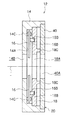
図18乃至図20に示すように、絞り駆動機構72は、絞りケース14と、5枚の絞り羽根16と、カムプレート18と、弾性表面波アクチュエータ20と、を備える。これらは、第1実施形態の絞り駆動機構12と同様の構成である。
As shown in FIGS. 18 to 20, the
カムプレート18のピン18Cが形成された面には、2ケの磁石74がカムプレート18の回転中心に対して略対称に取付けられている。また、圧電基板40のカムプレート18と対向する面には、2枚の磁性体76が取付けられており、各磁性体76が各磁石74に対向している。このため、各磁性体76が各磁石74に磁気的に吸引されてカムプレート18が圧電基板40側へ引寄せられてピン18Cが圧電基板40に圧接される。これによって、ピン18Cを圧電基板40に圧接するための機構を簡略化できる。
Two
また、絞りケース14の内周面には、ホール素子等の磁気センサ78が取付けられており、磁石74の位置が磁気センサ78によって検出される。また、磁気センサ78の出力には、CPU50(図2参照)が接続されており、CPU50が、磁気センサ78によって検出された磁石74の位置に基づいて、弾性表面波アクチュエータ20を制御して開口13の径を増減させる。
A
このように、ピン18Cを圧電基板40に圧接させるために設けられた磁石74が、カムプレート18の回動位置を検出するための検出子を兼ねるように構成したことで、カムプレート18の回動位置を検出するための機構の部品点数を低減でき、コストを低減できる。
As described above, the
なお、第1乃至第4実施形態では、デジタルカメラを例に取って本発明を説明したが、アナログカメラ等の他のカメラにも本発明を適用可能である。 In the first to fourth embodiments, the present invention has been described by taking a digital camera as an example. However, the present invention can also be applied to other cameras such as an analog camera.
10 デジタルカメラ(カメラ)
12 絞り駆動機構
16 絞り羽根
16B カムフォロアピン(移動子)
18 カムプレート
18C ピン(移動子)
20 弾性表面波アクチュエータ(カムプレート駆動手段)
40 圧電基板
42A 交差指状電極
42B 交差指状電極
52 絞り駆動機構
54 カムプレート
54C ピン(移動子)
56 弾性表面波アクチュエータ(カムプレート駆動手段)
58 圧電基板
62 絞り駆動機構
64 カムプレート
66 弾性表面波アクチュエータ(カムプレート駆動手段)
68 圧電基板
72 絞り駆動機構
74 磁石
76 磁性体
78 磁気センサ
10 Digital camera (camera)
12
18
20 Surface acoustic wave actuator (cam plate drive means)
40
56 Surface acoustic wave actuator (cam plate driving means)
58
68
Claims (6)
前記開口回りに回動して前記絞り羽根を回動させるカムプレートと、
前記カムプレートを回動させるカムプレート駆動手段と、を備える絞り駆動機構であって、
前記カムプレート駆動手段は、
前記カムプレートに設けられた移動子と、
前記移動子に圧接した圧電基板と、
前記圧電基板に設けられ、電圧を印加されて前記圧電基板に弾性表面波を発生させる交差指状電極と、
を有することを特徴とする絞り駆動機構。 A plurality of aperture blades that form an opening through which light passes and rotate to increase or decrease the diameter of the opening;
A cam plate that rotates around the opening to rotate the diaphragm blade;
A diaphragm driving mechanism comprising a cam plate driving means for rotating the cam plate,
The cam plate driving means includes
A mover provided on the cam plate;
A piezoelectric substrate in pressure contact with the mover;
An interdigital electrode that is provided on the piezoelectric substrate and generates a surface acoustic wave in the piezoelectric substrate by applying a voltage;
A diaphragm drive mechanism characterized by comprising:
前記圧電基板が前記カムプレートの外周縁部に沿って延在することを特徴とする請求項1に記載の絞り駆動機構。 The moving element protrudes from the outer peripheral edge of the cam plate in the radial direction of the opening,
The diaphragm drive mechanism according to claim 1, wherein the piezoelectric substrate extends along an outer peripheral edge of the cam plate.
前記磁石に面して設けられた磁性体と、
を有することを特徴とする請求項1又は2に記載の絞り駆動機構。 A magnet provided on a surface of the cam plate on which the moving element is formed;
A magnetic body provided facing the magnet;
The diaphragm drive mechanism according to claim 1, wherein:
前記磁気センサによって検出された前記磁石の位置に基づいて、前記開口の径を増減させる絞り制御手段と、
を有することを特徴とする請求項3に記載の絞り駆動機構。 A magnetic sensor for detecting the position of the magnet;
A diaphragm control means for increasing or decreasing the diameter of the opening based on the position of the magnet detected by the magnetic sensor;
The diaphragm drive mechanism according to claim 3, wherein:
前記絞り羽根を回動させる絞り羽根駆動手段と、
を備える絞り駆動機構であって、
前記絞り羽根駆動手段は、
前記絞り羽根に設けられた移動子と、
前記移動子に圧接した圧電基板と、
前記圧電基板に設けられ、電圧を印加されて前記圧電基板に弾性表面波を発生させる交差指状電極と、
を有することを特徴とする絞り駆動機構。 A plurality of aperture blades that form an opening through which light passes and rotate to increase or decrease the diameter of the opening;
A diaphragm blade driving means for rotating the diaphragm blade;
An aperture drive mechanism comprising:
The diaphragm blade driving means includes:
A moving element provided on the diaphragm blade;
A piezoelectric substrate in pressure contact with the mover;
An interdigital electrode that is provided on the piezoelectric substrate and generates a surface acoustic wave in the piezoelectric substrate by applying a voltage;
A diaphragm drive mechanism characterized by comprising:
Priority Applications (1)
| Application Number | Priority Date | Filing Date | Title |
|---|---|---|---|
| JP2005111027A JP2006292882A (en) | 2005-04-07 | 2005-04-07 | Diaphragm driving mechanism and camera |
Applications Claiming Priority (1)
| Application Number | Priority Date | Filing Date | Title |
|---|---|---|---|
| JP2005111027A JP2006292882A (en) | 2005-04-07 | 2005-04-07 | Diaphragm driving mechanism and camera |
Publications (2)
| Publication Number | Publication Date |
|---|---|
| JP2006292882A true JP2006292882A (en) | 2006-10-26 |
| JP2006292882A5 JP2006292882A5 (en) | 2008-05-15 |
Family
ID=37413551
Family Applications (1)
| Application Number | Title | Priority Date | Filing Date |
|---|---|---|---|
| JP2005111027A Abandoned JP2006292882A (en) | 2005-04-07 | 2005-04-07 | Diaphragm driving mechanism and camera |
Country Status (1)
| Country | Link |
|---|---|
| JP (1) | JP2006292882A (en) |
Cited By (6)
| Publication number | Priority date | Publication date | Assignee | Title |
|---|---|---|---|---|
| WO2009091766A1 (en) * | 2008-01-18 | 2009-07-23 | Apple Inc. | Dual-purpose hardware aperture |
| JP2010128358A (en) * | 2008-11-28 | 2010-06-10 | Nidec Copal Corp | Diaphragm device for camera |
| JP2015052782A (en) * | 2013-08-08 | 2015-03-19 | キヤノン株式会社 | Diaphragm device, lens device with the same, and imaging device with the same |
| US9608389B2 (en) | 2009-02-23 | 2017-03-28 | Apple Inc. | Audio jack with included microphone |
| US9866931B2 (en) | 2007-01-05 | 2018-01-09 | Apple Inc. | Integrated speaker assembly for personal media device |
| KR101945889B1 (en) | 2017-04-27 | 2019-02-11 | 삼성중공업 주식회사 | Cable fixing assembly |
Citations (5)
| Publication number | Priority date | Publication date | Assignee | Title |
|---|---|---|---|---|
| JPH05107591A (en) * | 1991-10-16 | 1993-04-30 | Canon Inc | Automatic diaphragm device |
| JPH07168245A (en) * | 1993-12-15 | 1995-07-04 | Olympus Optical Co Ltd | Diaphragm driving mechanism |
| JPH11295777A (en) * | 1998-04-10 | 1999-10-29 | Konica Corp | Diaphragm device |
| JP2001255570A (en) * | 2000-03-13 | 2001-09-21 | Minolta Co Ltd | Camera shutter mechanism |
| JP2001359287A (en) * | 2000-06-12 | 2001-12-26 | Minolta Co Ltd | Surface acoustic wave optical element |
-
2005
- 2005-04-07 JP JP2005111027A patent/JP2006292882A/en not_active Abandoned
Patent Citations (5)
| Publication number | Priority date | Publication date | Assignee | Title |
|---|---|---|---|---|
| JPH05107591A (en) * | 1991-10-16 | 1993-04-30 | Canon Inc | Automatic diaphragm device |
| JPH07168245A (en) * | 1993-12-15 | 1995-07-04 | Olympus Optical Co Ltd | Diaphragm driving mechanism |
| JPH11295777A (en) * | 1998-04-10 | 1999-10-29 | Konica Corp | Diaphragm device |
| JP2001255570A (en) * | 2000-03-13 | 2001-09-21 | Minolta Co Ltd | Camera shutter mechanism |
| JP2001359287A (en) * | 2000-06-12 | 2001-12-26 | Minolta Co Ltd | Surface acoustic wave optical element |
Cited By (10)
| Publication number | Priority date | Publication date | Assignee | Title |
|---|---|---|---|---|
| US9866931B2 (en) | 2007-01-05 | 2018-01-09 | Apple Inc. | Integrated speaker assembly for personal media device |
| WO2009091766A1 (en) * | 2008-01-18 | 2009-07-23 | Apple Inc. | Dual-purpose hardware aperture |
| CN101940077A (en) * | 2008-01-18 | 2011-01-05 | 苹果公司 | Dual-purpose hardware aperture |
| US8571205B2 (en) | 2008-01-18 | 2013-10-29 | Apple Inc. | Dual-purpose hardware aperture |
| CN101940077B (en) * | 2008-01-18 | 2013-11-20 | 苹果公司 | Dual-purpose hardware aperture |
| US8804947B2 (en) | 2008-01-18 | 2014-08-12 | Apple Inc. | Dual-purpose hardware aperture |
| JP2010128358A (en) * | 2008-11-28 | 2010-06-10 | Nidec Copal Corp | Diaphragm device for camera |
| US9608389B2 (en) | 2009-02-23 | 2017-03-28 | Apple Inc. | Audio jack with included microphone |
| JP2015052782A (en) * | 2013-08-08 | 2015-03-19 | キヤノン株式会社 | Diaphragm device, lens device with the same, and imaging device with the same |
| KR101945889B1 (en) | 2017-04-27 | 2019-02-11 | 삼성중공업 주식회사 | Cable fixing assembly |
Similar Documents
| Publication | Publication Date | Title |
|---|---|---|
| JP4140181B2 (en) | Electronic camera | |
| JP2004135029A (en) | Digital camera | |
| JP2007028512A (en) | Display device and imaging apparatus | |
| JP2010171964A (en) | Imaging apparatus | |
| JP2006292882A (en) | Diaphragm driving mechanism and camera | |
| JP2008054177A (en) | Imaging apparatus | |
| JP4284440B2 (en) | Electronic camera | |
| JP2007079157A (en) | Image display apparatus and photographing apparatus | |
| JP2008003130A (en) | Image stabilizing apparatus and photographing apparatus | |
| JP2011114788A (en) | Imaging apparatus and imaging method | |
| JP5203657B2 (en) | Camera with enlarged display function | |
| US8924856B2 (en) | Method of and apparatus for providing a slide show, and computer readable storage medium having recorded thereon a computer program for providing a slide show | |
| JP2006293083A (en) | Lens drive mechanism and camera | |
| JP4025836B2 (en) | Imaging device and portable communication device | |
| JP2005292325A (en) | Camera, imaging apparatus, lens barrel and camera main body | |
| JP4581780B2 (en) | Display device with touch panel | |
| JP4339370B2 (en) | Camera, imaging device, lens barrel and camera body | |
| JP4369350B2 (en) | Imaging device | |
| JP5034969B2 (en) | Imaging apparatus, imaging method, and program | |
| CN107645631A (en) | The start up process method and recording medium of camera device, camera device | |
| US9204057B2 (en) | Imaging apparatus for shading correction | |
| JP2004118033A (en) | Camera | |
| JP5200815B2 (en) | Imaging apparatus and program thereof | |
| JP2007248904A (en) | Real image type observation optical system, photographic lens barrel unit and imaging apparatus | |
| JP5049313B2 (en) | camera |
Legal Events
| Date | Code | Title | Description |
|---|---|---|---|
| A711 | Notification of change in applicant |
Effective date: 20070201 Free format text: JAPANESE INTERMEDIATE CODE: A712 |
|
| A521 | Written amendment |
Effective date: 20080327 Free format text: JAPANESE INTERMEDIATE CODE: A523 |
|
| A621 | Written request for application examination |
Effective date: 20080327 Free format text: JAPANESE INTERMEDIATE CODE: A621 |
|
| A977 | Report on retrieval |
Free format text: JAPANESE INTERMEDIATE CODE: A971007 Effective date: 20110113 |
|
| A131 | Notification of reasons for refusal |
Free format text: JAPANESE INTERMEDIATE CODE: A131 Effective date: 20110118 |
|
| A521 | Written amendment |
Free format text: JAPANESE INTERMEDIATE CODE: A523 Effective date: 20110224 |
|
| A131 | Notification of reasons for refusal |
Effective date: 20110419 Free format text: JAPANESE INTERMEDIATE CODE: A131 |
|
| A762 | Written abandonment of application |
Effective date: 20110509 Free format text: JAPANESE INTERMEDIATE CODE: A762 |