JP2006284619A - Image display apparatus - Google Patents
Image display apparatus Download PDFInfo
- Publication number
- JP2006284619A JP2006284619A JP2005100407A JP2005100407A JP2006284619A JP 2006284619 A JP2006284619 A JP 2006284619A JP 2005100407 A JP2005100407 A JP 2005100407A JP 2005100407 A JP2005100407 A JP 2005100407A JP 2006284619 A JP2006284619 A JP 2006284619A
- Authority
- JP
- Japan
- Prior art keywords
- light
- polarization axis
- polarization
- observer
- display panel
- Prior art date
- Legal status (The legal status is an assumption and is not a legal conclusion. Google has not performed a legal analysis and makes no representation as to the accuracy of the status listed.)
- Pending
Links
Images


Classifications
-
- G—PHYSICS
- G02—OPTICS
- G02F—OPTICAL DEVICES OR ARRANGEMENTS FOR THE CONTROL OF LIGHT BY MODIFICATION OF THE OPTICAL PROPERTIES OF THE MEDIA OF THE ELEMENTS INVOLVED THEREIN; NON-LINEAR OPTICS; FREQUENCY-CHANGING OF LIGHT; OPTICAL LOGIC ELEMENTS; OPTICAL ANALOGUE/DIGITAL CONVERTERS
- G02F1/00—Devices or arrangements for the control of the intensity, colour, phase, polarisation or direction of light arriving from an independent light source, e.g. switching, gating or modulating; Non-linear optics
- G02F1/01—Devices or arrangements for the control of the intensity, colour, phase, polarisation or direction of light arriving from an independent light source, e.g. switching, gating or modulating; Non-linear optics for the control of the intensity, phase, polarisation or colour
- G02F1/13—Devices or arrangements for the control of the intensity, colour, phase, polarisation or direction of light arriving from an independent light source, e.g. switching, gating or modulating; Non-linear optics for the control of the intensity, phase, polarisation or colour based on liquid crystals, e.g. single liquid crystal display cells
- G02F1/133—Constructional arrangements; Operation of liquid crystal cells; Circuit arrangements
- G02F1/1333—Constructional arrangements; Manufacturing methods
- G02F1/1335—Structural association of cells with optical devices, e.g. polarisers or reflectors
-
- H—ELECTRICITY
- H04—ELECTRIC COMMUNICATION TECHNIQUE
- H04N—PICTORIAL COMMUNICATION, e.g. TELEVISION
- H04N13/00—Stereoscopic video systems; Multi-view video systems; Details thereof
- H04N13/30—Image reproducers
- H04N13/302—Image reproducers for viewing without the aid of special glasses, i.e. using autostereoscopic displays
- H04N13/31—Image reproducers for viewing without the aid of special glasses, i.e. using autostereoscopic displays using parallax barriers
-
- G—PHYSICS
- G02—OPTICS
- G02B—OPTICAL ELEMENTS, SYSTEMS OR APPARATUS
- G02B30/00—Optical systems or apparatus for producing three-dimensional [3D] effects, e.g. stereoscopic images
- G02B30/20—Optical systems or apparatus for producing three-dimensional [3D] effects, e.g. stereoscopic images by providing first and second parallax images to an observer's left and right eyes
- G02B30/22—Optical systems or apparatus for producing three-dimensional [3D] effects, e.g. stereoscopic images by providing first and second parallax images to an observer's left and right eyes of the stereoscopic type
- G02B30/25—Optical systems or apparatus for producing three-dimensional [3D] effects, e.g. stereoscopic images by providing first and second parallax images to an observer's left and right eyes of the stereoscopic type using polarisation techniques
-
- G—PHYSICS
- G02—OPTICS
- G02B—OPTICAL ELEMENTS, SYSTEMS OR APPARATUS
- G02B30/00—Optical systems or apparatus for producing three-dimensional [3D] effects, e.g. stereoscopic images
- G02B30/20—Optical systems or apparatus for producing three-dimensional [3D] effects, e.g. stereoscopic images by providing first and second parallax images to an observer's left and right eyes
- G02B30/26—Optical systems or apparatus for producing three-dimensional [3D] effects, e.g. stereoscopic images by providing first and second parallax images to an observer's left and right eyes of the autostereoscopic type
- G02B30/27—Optical systems or apparatus for producing three-dimensional [3D] effects, e.g. stereoscopic images by providing first and second parallax images to an observer's left and right eyes of the autostereoscopic type involving lenticular arrays
-
- G—PHYSICS
- G02—OPTICS
- G02B—OPTICAL ELEMENTS, SYSTEMS OR APPARATUS
- G02B30/00—Optical systems or apparatus for producing three-dimensional [3D] effects, e.g. stereoscopic images
- G02B30/20—Optical systems or apparatus for producing three-dimensional [3D] effects, e.g. stereoscopic images by providing first and second parallax images to an observer's left and right eyes
- G02B30/26—Optical systems or apparatus for producing three-dimensional [3D] effects, e.g. stereoscopic images by providing first and second parallax images to an observer's left and right eyes of the autostereoscopic type
- G02B30/30—Optical systems or apparatus for producing three-dimensional [3D] effects, e.g. stereoscopic images by providing first and second parallax images to an observer's left and right eyes of the autostereoscopic type involving parallax barriers
- G02B30/31—Optical systems or apparatus for producing three-dimensional [3D] effects, e.g. stereoscopic images by providing first and second parallax images to an observer's left and right eyes of the autostereoscopic type involving parallax barriers involving active parallax barriers
Landscapes
- Physics & Mathematics (AREA)
- General Physics & Mathematics (AREA)
- Optics & Photonics (AREA)
- Nonlinear Science (AREA)
- Multimedia (AREA)
- Signal Processing (AREA)
- Engineering & Computer Science (AREA)
- Mathematical Physics (AREA)
- Chemical & Material Sciences (AREA)
- Crystallography & Structural Chemistry (AREA)
- Liquid Crystal (AREA)
- Stereoscopic And Panoramic Photography (AREA)
- Testing, Inspecting, Measuring Of Stereoscopic Televisions And Televisions (AREA)
Abstract
Description
この発明は、画像表示装置に関し、特に、立体画像を表示することが可能な画像表示装置に関する。 The present invention relates to an image display device, and more particularly to an image display device capable of displaying a stereoscopic image.
従来、3次元の立体画像を表示することが可能な3次元画像表示装置が知られている(たとえば、特許文献1参照)。 Conventionally, a three-dimensional image display device capable of displaying a three-dimensional stereoscopic image is known (see, for example, Patent Document 1).
上記特許文献1には、画像表示面の観察者側に配置された電子式パララックスバリアを、マイクロコンピュータなどの制御手段により制御することによって、電子式パララックスバリアの所定の位置に、所定の形状の開口部および遮光部を観察者の左目および右目を結んだ線分に対して実質的に垂直方向にストライプ状に形成することが可能な3次元画像表示装置が開示されている。この特許文献1に開示された3次元画像表示装置では、観察者に3次元画像を提供する場合には、観察者の左目に左眼用の画像が入射するとともに、観察者の右目に右目用画像が入射するように、電子式パララックスバリアの開口部が形成される。
In
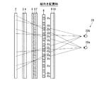
また、従来、表示パネルの観察者側にスリット状の開口部および遮光部が設けられたバリアを配置することによって、観察者に立体画像を提示可能な立体画像表示装置が提案されている。図17は、従来の一例による立体画像表示装置の原理を説明するための平面図である。図17を参照して、従来の立体画像表示装置500の構成について説明する。
Conventionally, there has been proposed a stereoscopic image display device capable of presenting a stereoscopic image to an observer by disposing a barrier provided with a slit-shaped opening and a light shielding portion on the viewer side of the display panel. FIG. 17 is a plan view for explaining the principle of a conventional stereoscopic image display apparatus. With reference to FIG. 17, a configuration of a conventional stereoscopic
従来の立体画像表示装置500は、図17に示すように、画像を表示するための表示パネル501と、表示パネル501の観察者510側に配置された偏光板502と、偏光板502の観察者510側に設けられたバリア503とを備えている。
As shown in FIG. 17, a conventional stereoscopic
また、表示パネル501は、ガラス基板501aを有している。また、表示パネル501には、観察者510の左目510aと右目510bとを結んだ線分に対して実質的に直交する方向(図17の紙面に対して垂直方向)に延びる画素列501bおよび画素列501cが交互に設けられている。この画素列501bには、観察者510の左目510aが見るための画像L10が表示されているとともに、画素列501cには、観察者510の右目510bが見るための画像R10が表示されている。
The
また、バリア503には、表示パネル501から出射された光を遮光するための遮光部503aと、表示パネル501から出射された光を透過させるための開口部503bとが設けられている。この遮光部503aおよび開口部503bは、表示パネル501の画素列501bおよび501cと同様に、観察者510の左目510aおよび右目510bを結んだ線分に対して実質的に直交する方向(図17の紙面に対して垂直な方向)に延びるように交互に設けられている。また、遮光部503aおよび開口部503bは、表示パネル501の画素列501bおよび501cからなる組毎に対応して設けられている。
In addition, the
次に、図17を参照して、従来の立体画像表示装置500による立体画像表示方法について説明する。
Next, a stereoscopic image display method by the conventional stereoscopic
従来の立体画像表示装置500では、観察者510がバリア503の開口部503bを介して表示パネル501を観察する場合、観察者510の左目510aには、表示パネル501の画素列501bに表示されている画像L10が入射されるとともに、観察者510の右目510bには、表示パネル501の画素列501cに表示されている画像R10が入射される。これにより、観察者510が、立体画像を観察することが可能となる。
In the conventional stereoscopic
しかしながら、図17に示した従来の立体画像表示装置500では、立体画像表示装置500を、たとえば、縦向きに配置した場合にのみ観察者510に立体画像を提供するように対応させており、立体画像表示装置500を、たとえば、横向きに配置した場合には、観察者510に立体画像を提供することが困難であるという問題点があった。
However, in the conventional stereoscopic
また、上記特許文献1も同様な問題点がある。
The above-mentioned
この発明は、上記のような課題を解決するためになされたものであり、この発明の1つの目的は、縦向きに配置した場合および横向きに配置した場合の両方の場合に、観察者に立体画像を提供することが可能な画像表示装置を提供することである。 The present invention has been made to solve the above-described problems, and one object of the present invention is to provide an observer with a three-dimensional view both in the case of being arranged vertically and in the case of being arranged horizontally. An object of the present invention is to provide an image display device capable of providing an image.
上記目的を達成するために、この発明の一の局面による画像表示装置は、画像を表示するための表示パネルと、表示パネルに光を照射するための光源と、光源から照射された光を第1の偏光軸を有する光と、第2の偏光軸を有する光とに分離するための第1偏光軸制御手段と、光源から照射された光を第3の偏光軸を有する光と、第4の偏光軸を有する光とに分離するための第2偏光軸制御手段とを備え、表示パネルが第1の方向に配置された状態で、第1の偏光軸を有する光および第2の偏光軸を有する光の一方を観察者の目に向かって進行させることにより、観察者に立体画像を提供するとともに、表示パネルが第1の方向と交差する第2の方向に配置された状態で、第3の偏光軸を有する光および第4の偏光軸を有する光の一方を観察者の目に進行させることにより、観察者に立体画像を提供する。 In order to achieve the above object, an image display device according to an aspect of the present invention provides a display panel for displaying an image, a light source for irradiating light on the display panel, and light emitted from the light source. First polarization axis control means for separating light having a first polarization axis and light having a second polarization axis, light having a third polarization axis from light emitted from the light source, and fourth And a second polarization axis control means for separating the light having the first polarization axis and the light having the first polarization axis and the second polarization axis in a state where the display panel is disposed in the first direction. By moving one of the light beams having an angle toward the eyes of the observer, the stereoscopic image is provided to the observer, and the display panel is disposed in the second direction intersecting the first direction. Observation of one of light having a third polarization axis and light having a fourth polarization axis By proceeding in the eye, to provide stereoscopic images to the observer.
この一の局面による画像表示装置では、上記のように、第1偏光軸制御手段と第2偏光軸制御手段とを設けるとともに、表示パネルが第1の方向に配置された状態で、光源から照射されて第1偏光軸制御手段により分離された第1の偏光軸を有する光および第2の偏光軸を有する光の一方を観察者の目に向かって進行させることにより、観察者に立体画像を提供し、かつ、表示パネルが第1の方向と交差する第2の方向に配置された状態で、光源から照射されて第2偏光軸制御手段により分離された第3の偏光軸を有する光および第4の偏光軸を有する光の一方を観察者の目に向かって進行させることにより、観察者に立体画像を提供することによって、表示パネルを第1の方向(縦向き)に配置した場合および第2の方向(横向き)に配置した場合の両方の場合に、観察者に立体画像を提供することができる。 In the image display device according to the one aspect, as described above, the first polarization axis control unit and the second polarization axis control unit are provided, and the display panel is arranged in the first direction and irradiated from the light source. By moving one of the light having the first polarization axis and the light having the second polarization axis separated by the first polarization axis control means toward the observer's eyes, the stereoscopic image is displayed to the observer. And having a third polarization axis emitted from the light source and separated by the second polarization axis control means in a state where the display panel is arranged in a second direction intersecting the first direction. When the display panel is arranged in the first direction (longitudinal direction) by providing a stereoscopic image to the observer by advancing one of the lights having the fourth polarization axis toward the eyes of the observer; Arranged in the second direction (landscape) In both cases the can provide stereoscopic images to the observer.
上記一の局面による画像表示装置において、好ましくは、表示パネルが第1の方向に配置された状態で、第1の偏光軸を有する光および第2の偏光軸を有する光の一方により、左目用画像を観察者の左目に向かって進行させるとともに、右目用画像を観察者の右目に向かって進行させることによって、観察者に立体画像を提供し、表示パネルが第1の方向と交差する第2の方向に配置された状態で、第3の偏光軸を有する光および第4の偏光軸を有する光の一方により、左目用画像を観察者の左目に向かって進行させるとともに、右目用画像を観察者の右目に向かって進行させることによって、観察者に立体画像を提供する。このように構成すれば、表示パネルを第1の方向(縦向き)に配置した場合および第2の方向(横向き)に配置した場合の両方の場合に、容易に、観察者に立体画像を提供することができる。 In the image display device according to the above aspect, it is preferable for the left eye to emit one of the light having the first polarization axis and the light having the second polarization axis in a state where the display panel is arranged in the first direction. The image is advanced toward the left eye of the observer and the image for the right eye is advanced toward the right eye of the observer, thereby providing the observer with a stereoscopic image, and the second display panel crosses the first direction. The left-eye image is advanced toward the left eye of the observer and the right-eye image is observed by one of the light having the third polarization axis and the light having the fourth polarization axis. The stereoscopic image is provided to the observer by proceeding toward the right eye of the observer. With this configuration, a stereoscopic image can be easily provided to an observer in both cases where the display panel is arranged in the first direction (vertical direction) and in the second direction (horizontal direction). can do.
上記一の局面による画像表示装置において、好ましくは、第1偏光軸制御手段は、光源から照射された光を第1の偏光軸を有する光に制御するための複数の第1偏光制御領域と、光源から照射された光を第2の偏光軸を有する光に制御するための複数の第2偏光制御領域とを含み、複数の第1偏光制御領域および複数の第2偏光制御領域は、表示パネルが第1の方向に配置された状態で、階段状に配置されている。このように構成すれば、斜め方向に延びる階段状に配置された複数の第1偏光制御領域および複数の第2偏光制御領域により、第1の偏光軸を有する光および第2の偏光軸を有する光の一方を、縦方向および横方向にほぼ均等に分散した状態で観察者の目に向かって進行させることができるので、表示パネルの画像の解像度の低下を縦方向と横方向とに分散することができる。これにより、画像劣化の少ない立体画像を観察者に提供することができる。 In the image display device according to the above aspect, preferably, the first polarization axis control unit includes a plurality of first polarization control regions for controlling light emitted from the light source to light having the first polarization axis, A plurality of second polarization control regions for controlling light emitted from the light source to light having a second polarization axis, and the plurality of first polarization control regions and the plurality of second polarization control regions include a display panel Are arranged in a staircase shape in a state arranged in the first direction. If comprised in this way, it has the light which has the 1st polarization axis, and the 2nd polarization axis by a plurality of 1st polarization control fields and a plurality of 2nd polarization control fields which are arranged in the shape of a step which extends in the slanting direction. Since one of the light can travel toward the viewer's eyes in a state of being evenly distributed in the vertical and horizontal directions, the reduction in the resolution of the image on the display panel is distributed in the vertical and horizontal directions. be able to. Thereby, a stereoscopic image with little image degradation can be provided to an observer.
上記第1偏光軸制御手段が第1偏光制御領域および第2偏光制御領域を含む画像表示装置において、好ましくは、表示パネルは、光の3原色を表示するための複数のドット領域を含み、第1偏光軸制御手段の第1偏光制御領域および第2偏光制御領域は、それぞれ、表示パネルの各々のドット領域毎に配置されている。このように構成すれば、ドット領域毎に設けられた第1偏光制御領域および第2偏光制御領域により、表示パネルの画像を細分化した状態で観察者の目に入射させることができる。これにより、より画像劣化の少ない立体画像を観察者に提供することができる。 In the image display device in which the first polarization axis control unit includes a first polarization control region and a second polarization control region, preferably, the display panel includes a plurality of dot regions for displaying the three primary colors of light, The first polarization control region and the second polarization control region of the one polarization axis control means are respectively arranged for each dot region of the display panel. If comprised in this way, the image of a display panel can be made to inject into an observer's eyes in the state divided by the 1st polarization | polarized-light control area | region and 2nd polarization | polarized-light control area | region provided for every dot area | region. Thereby, a stereoscopic image with less image degradation can be provided to the observer.
上記一の局面による画像表示装置において、好ましくは、第1偏光軸制御手段は、位相差板を含む。このように位相差板を用いれば、光源から照射された光を第1の偏光軸を有する光と第2の偏光軸を有する光とに、容易に、分離することができる。 In the image display device according to the above aspect, the first polarization axis control unit preferably includes a retardation plate. If the retardation plate is used in this way, the light emitted from the light source can be easily separated into light having the first polarization axis and light having the second polarization axis.
上記一の局面による画像表示装置において、好ましくは、第2偏光軸制御手段は、光源から照射された光を第3の偏光軸を有する光に制御するための複数の第3偏光制御領域と、光源から照射された光を第4の偏光軸を有する光に制御するための複数の第4偏光制御領域とを含み、第3偏光制御領域および第4偏光制御領域は、表示パネルが第2の方向に配置された状態で、観察者の左右の目を結んだ方向に対して実質的に垂直方向に延びるとともに、観察者の左右の目を結んだ方向に沿った方向に交互に配置されている。このように構成すれば、表示パネルが第2の方向に配置された状態で、観察者の左右の目を結んだ方向に対して実質的に垂直方向に延びる第3偏光制御領域および第4偏光制御領域により、第3の偏光軸を有する光および第4の偏光軸を有する光の一方を、容易に、観察者の目に向かって進行させることができるので、容易に、表示パネルが第2の方向に配置された状態で、立体画像を観察者に提供することができる。 In the image display device according to the above aspect, preferably, the second polarization axis control means includes a plurality of third polarization control regions for controlling the light emitted from the light source to the light having the third polarization axis, A plurality of fourth polarization control regions for controlling the light emitted from the light source to light having the fourth polarization axis, and the third polarization control region and the fourth polarization control region have the second display panel In a state of being arranged in the direction, it extends in a direction substantially perpendicular to the direction connecting the left and right eyes of the observer, and is alternately arranged in a direction along the direction connecting the left and right eyes of the observer Yes. With this configuration, the third polarization control region and the fourth polarization that extend substantially perpendicular to the direction connecting the left and right eyes of the observer with the display panel arranged in the second direction. Since one of the light having the third polarization axis and the light having the fourth polarization axis can be easily advanced toward the observer's eyes by the control region, the display panel can be easily moved to the second position. A stereoscopic image can be provided to the observer in a state where the three-dimensional image is arranged in the direction.
上記第2偏光軸制御手段が第3偏光制御領域および第4偏光制御領域を含む画像表示装置において、好ましくは、表示パネルは、光の3原色をそれぞれ表示するための3つのドット領域を含み、第2偏光軸制御手段の第3偏光制御領域および第4偏光制御領域の観察者の左右の目を結んだ方向に沿った方向の長さは、ドット領域の観察者の左右の目を結んだ方向に沿った方向の長さに実質的に対応するように設定されており、表示パネルの光の3原色をそれぞれ表示するための3つのドット領域は、表示パネルが第2の方向に配置された状態で、観察者の左右の目を結んだ方向に対して実質的に垂直方向に隣接するように配置される。このように構成すれば、観察者の左右の目を結んだ方向に対して実質的に垂直に延びるように設けられた第3偏光制御領域および第4偏光制御領域に、それぞれ、光の3原色に対応する3つのドット領域を配置することができるので、観察者に画像劣化の少ない立体画像を提供することができる。 In the image display device in which the second polarization axis control means includes a third polarization control region and a fourth polarization control region, preferably, the display panel includes three dot regions for displaying the three primary colors of light, The length in the direction along the direction connecting the left and right eyes of the observer in the third polarization control region and the fourth polarization control region of the second polarization axis control means connected the left and right eyes of the observer in the dot region. It is set so as to substantially correspond to the length of the direction along the direction, and in the three dot areas for displaying the three primary colors of the light of the display panel, the display panel is arranged in the second direction. In this state, they are arranged so as to be adjacent to each other in a substantially vertical direction with respect to the direction connecting the left and right eyes of the observer. With this configuration, the three primary colors of light are respectively provided in the third polarization control region and the fourth polarization control region provided so as to extend substantially perpendicular to the direction connecting the left and right eyes of the observer. Since the three dot regions corresponding to can be arranged, a stereoscopic image with little image deterioration can be provided to the observer.
上記第2偏光軸制御手段が第3偏光制御領域および第4偏光制御領域を含む画像表示装置において、好ましくは、第2偏光軸制御手段は、第3偏光制御領域および第4偏光制御領域を有する第1偏光制御液晶パネルを含み、第1偏光制御液晶パネルの第3偏光制御領域および第4偏光制御領域には、それぞれ、液晶に電圧を印加するための電極が第3偏光制御領域および第4偏光制御領域と同じ方向に延びるように形成されている。このように構成すれば、第1偏光制御液晶パネルの電極を用いて、第3偏光制御領域および第4偏光制御領域の液晶に電圧を印加することができるので、液晶の電圧の印加状態を制御することによって、第3偏光制御領域および第4偏光制御領域の偏光制御状態を容易に変化させることができる。これにより、第2の方向に配置された場合のみ、偏光制御を行うようにすることができる。 In the image display device in which the second polarization axis control means includes a third polarization control area and a fourth polarization control area, preferably, the second polarization axis control means has a third polarization control area and a fourth polarization control area. An electrode for applying a voltage to the liquid crystal is provided in each of the third polarization control region and the fourth polarization control region of the first polarization control liquid crystal panel. It is formed to extend in the same direction as the polarization control region. According to this configuration, voltage can be applied to the liquid crystals in the third polarization control region and the fourth polarization control region using the electrodes of the first polarization control liquid crystal panel, so that the voltage application state of the liquid crystal is controlled. By doing so, the polarization control states of the third polarization control region and the fourth polarization control region can be easily changed. Thereby, it is possible to perform polarization control only when arranged in the second direction.
上記一の局面による画像表示装置において、好ましくは、表示パネルが第1の方向に配置された状態で、第1の偏光軸を有する光を第5の偏光軸を有する光に制御するとともに、第2の偏光軸を有する光を第6の偏光軸を有する光に制御し、第2の方向に配置された状態で、第1の偏光軸を有する光および第2の偏光軸を有する光を、偏光軸を制御せずに透過させる第3偏光軸制御手段をさらに備える。このように構成すれば、第3偏光軸制御手段により、表示パネルが第1の方向に配置されている場合のみ、偏光制御を行うことができるとともに、表示パネルが第2の方向に配置されている場合には、偏光制御を行わないようにすることができる。 In the image display device according to the above aspect, preferably, the light having the first polarization axis is controlled to the light having the fifth polarization axis in a state where the display panel is arranged in the first direction. The light having the second polarization axis is controlled to the light having the sixth polarization axis, and the light having the first polarization axis and the light having the second polarization axis are arranged in the second direction. Third polarization axis control means for transmitting without controlling the polarization axis is further provided. With this configuration, the third polarization axis control unit can perform polarization control only when the display panel is arranged in the first direction, and the display panel is arranged in the second direction. If so, polarization control can be avoided.
上記第3偏光軸制御手段を備える画像表示装置において、好ましくは、第3偏光軸制御手段は、第1の偏光軸を有する光を第5の偏光軸を有する光に制御するとともに、第2の偏光軸を有する光を第6の偏光軸を有する光に制御する第1の状態と、第1の偏光軸を有する光および第2の偏光軸を有する光を、偏光軸を制御せずに透過させる第2の状態とを切り換え可能な第2偏光制御液晶パネルを含む。このように構成すれば、第2偏光制御液晶パネルにより、表示パネルが第1の方向に配置されている場合、および、表示パネルが第2の方向に配置されている場合に応じて、上記第1の状態と第2の状態とを切り換えることができるので、容易に、表示パネルの配置状態に応じて偏光制御の有無を切り換えることができる。 In the image display device including the third polarization axis control means, preferably, the third polarization axis control means controls the light having the first polarization axis to the light having the fifth polarization axis, and the second The first state in which the light having the polarization axis is controlled to the light having the sixth polarization axis, and the light having the first polarization axis and the light having the second polarization axis are transmitted without controlling the polarization axis. A second polarization control liquid crystal panel that can be switched between the second state and the second state. If comprised in this way, according to the case where the display panel is arrange | positioned by the 2nd polarization control liquid crystal panel in a 1st direction, and the case where a display panel is arrange | positioned in a 2nd direction, said 2nd Since the first state and the second state can be switched, the presence / absence of polarization control can be easily switched according to the arrangement state of the display panel.
上記一の局面による画像表示装置において、好ましくは、第1偏光軸制御手段および第2偏光軸制御手段は、表示パネルを挟み込むように配置される。このように構成すれば、たとえば、表示パネルと第1偏光軸制御手段との間に第2偏光軸制御手段を配置する場合に比べて、表示パネルと第1偏光軸制御手段との間隔を小さくすることができるので、表示パネルからの適視距離を小さくすることができる。これにより、本発明の画像表示装置を表示パネルが小さい携帯電話などに用いた場合に、表示パネルから観察者の目までの距離(適視距離)を小さくすることができるので、表示パネルの立体画像を見やすくすることができる。 In the image display device according to the above aspect, the first polarization axis control means and the second polarization axis control means are preferably arranged so as to sandwich the display panel. If comprised in this way, the space | interval of a display panel and a 1st polarization axis control means will be made small compared with the case where a 2nd polarization axis control means is arrange | positioned between a display panel and a 1st polarization axis control means, for example. Therefore, the appropriate viewing distance from the display panel can be reduced. Accordingly, when the image display device of the present invention is used for a mobile phone having a small display panel, the distance from the display panel to the observer's eyes (appropriate viewing distance) can be reduced. The image can be made easy to see.
上記一の局面による画像表示装置において、好ましくは、第1の偏光軸を有する光を第5の偏光軸を有する光に制御するとともに、第2の偏光軸を有する光を第6の偏光軸を有する光に制御する第3偏光軸制御手段をさらに備え、第2偏光軸制御手段は、第3の偏光軸を有する光および第4の偏光軸を有する光の一方を観察者の目に向かって進行させる場合と、第3の偏光軸を有する光および第4の偏光軸を有する光の両方を観察者の目に向かって進行させる場合とに切り換え可能であるとともに、第3偏光軸制御手段は、第5の偏光軸を有する光および第6の偏光軸を有する光の一方を観察者の目に向かって進行させる場合と、第5の偏光軸を有する光および第6の偏光軸を有する光の両方を観察者の目に向かって進行させる場合とに切り換え可能であり、第2偏光軸制御手段が、第3の偏光軸を有する光および第4の偏光軸を有する光の両方を観察者の目に向かって進行させるとともに、第3偏光軸制御手段が、第5の偏光軸を有する光および第6の偏光軸を有する光の両方を観察者の目に向かって進行させることによって、観察者に平面画像を提供する。このように構成すれば、第2偏光軸制御手段を、第3の偏光軸を有する光および第4の偏光軸を有する光の一方を観察者の目に向かって進行させる場合と、第3の偏光軸を有する光および第4の偏光軸を有する光の両方を観察者の目に向かって進行させる場合とに切り換えるとともに、第3偏光軸制御手段を、第5の偏光軸を有する光および第6の偏光軸を有する光の一方を観察者の目に向かって進行させる場合と、第5の偏光軸を有する光および第6の偏光軸を有する光の両方を観察者の目に向かって進行させる場合とに切り換えることにより、1つの画像表示装置で、観察者に立体画像および平面画像の両方を提供することができる。 In the image display device according to the above aspect, preferably, the light having the first polarization axis is controlled to the light having the fifth polarization axis, and the light having the second polarization axis is changed to the sixth polarization axis. And further comprising third polarization axis control means for controlling the light having light, and the second polarization axis control means directs one of the light having the third polarization axis and the light having the fourth polarization axis to the eyes of the observer. The third polarization axis control means can be switched between a case where the light travels and a case where both the light having the third polarization axis and the light having the fourth polarization axis travel toward the eyes of the observer. , One of the light having the fifth polarization axis and the light having the sixth polarization axis traveling toward the observer's eyes, and the light having the fifth polarization axis and the light having the sixth polarization axis And if both are advanced toward the observer's eyes And the second polarization axis control means advances both the light having the third polarization axis and the light having the fourth polarization axis toward the eyes of the observer, and the third polarization axis control means. Provides a planar image to the viewer by traveling both light having the fifth polarization axis and light having the sixth polarization axis toward the viewer's eyes. According to this structure, the second polarization axis control unit causes the light having the third polarization axis and the light having the fourth polarization axis to travel toward the eyes of the observer, Switching between the case where both the light having the polarization axis and the light having the fourth polarization axis travel toward the eyes of the observer, and the third polarization axis control means is configured to change the light having the fifth polarization axis and the light having the fifth polarization axis. One of the light beams having the six polarization axes travels toward the viewer's eyes, and the light beam having the fifth polarization axis and the light having the sixth polarization axes travels toward the viewer's eyes. By switching to the case of making it to be performed, it is possible to provide both the stereoscopic image and the planar image to the observer with one image display device.
以下、本発明を具体化した実施形態を図面に基づいて説明する。 DESCRIPTION OF THE PREFERRED EMBODIMENTS Embodiments embodying the present invention will be described below with reference to the drawings.
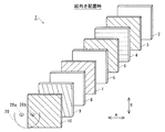
図1は、本発明の一実施形態による画像表示装置を示した分解斜視図である。図2は、図1に示した本発明の一実施形態による表示パネルを縦向き(図1の状態)に配置した場合の立体画像表示時において観察者が表示パネルを見た状態を上方から示した図である。図3は、図1に示した本発明の一実施形態による表示パネルを横向き(図1を90°回転させた状態)に配置した場合の立体画像表示時において観察者が表示パネルを見た状態を上方から示した図である。図4〜図7は、図1に示した本発明の一実施形態による画像表示装置の構成を詳細に説明するための図である。まず、図1〜図7を参照して、本発明の一実施形態による画像表示装置1の構成について説明する。
FIG. 1 is an exploded perspective view illustrating an image display apparatus according to an embodiment of the present invention. FIG. 2 shows from above the state in which the viewer looks at the display panel during stereoscopic image display when the display panel according to the embodiment of the present invention shown in FIG. 1 is arranged vertically (the state shown in FIG. 1). It is a figure. FIG. 3 shows a state in which the viewer looks at the display panel when displaying a stereoscopic image when the display panel according to the embodiment of the present invention shown in FIG. 1 is placed sideways (a state where FIG. 1 is rotated by 90 °). It is the figure which showed from above. 4 to 7 are diagrams for explaining in detail the configuration of the image display apparatus according to the embodiment of the present invention shown in FIG. First, the configuration of an
本発明の一実施形態による画像表示装置1は、図1に示すように、バックライト2と、バックライト2の光出射側に配置される偏光板3と、偏光板3の光出射側に配置される横向き用の偏光制御液晶パネル4(以下、「横向き用液晶パネル4」という)と、横向き用液晶パネル4の光出射側に配置され、画像を表示する液晶表示パネルからなる表示パネル5と、表示パネル5を挟み込むように配置される偏光板6および7と、偏光板7の光出射側に配置される位相差板8と、位相差板8の光出射側に配置される縦向き用の偏光制御液晶パネル9(以下、「縦向き用液晶パネル9」という)と、縦向き用液晶パネル9の光出射側に配置される偏光板10とを備えている。なお、バックライト2は、本発明の「光源」の一例であり、横向き用液晶パネル4は、本発明の「第2偏光軸制御手段」および「第1偏光制御液晶パネル」の一例である。また、位相差板8は、本発明の「第1偏光軸制御手段」の一例であり、縦向き用液晶パネル9は、本発明の「第3偏光軸制御手段」および「第2偏光制御液晶パネル」の一例である。
As shown in FIG. 1, an
また、バックライト2は、偏光板3に光を照射する機能を有する。また、偏光板3は観察者20側から見て約135°の偏光軸を有しているので、観察者20側から見て約135°の偏光軸を有する光のみを透過する機能を有する。なお、本実施形態では、偏光軸の角度は、表示パネル5を縦向きに配置した状態における角度を示す。
The
また、横向き用液晶パネル4は、図4に示すように、偏光制御領域4aおよび4bを有している。なお、偏光制御領域4aは、本発明の「第3偏光制御領域」の一例であり、偏光制御領域4bは、本発明の「第4偏光制御領域」の一例である。また、偏光制御領域4aおよび4bは、表示パネル5(図1参照)を横向きに配置した場合(図3および図4の場合)には、観察者20(図3参照)の左目20aと右目20bとを結んだ線分に対して実質的に垂直方向(A方向)に延びるように配置されている。また、偏光制御領域4aおよび4bには、それぞれ、A方向に延びる電極4cが設けられている。これにより、横向き用液晶パネル4の偏光制御領域4aおよび4bに位置する液晶に電極4cを用いて電圧を印加することが可能となるので、液晶への電圧の印加状態を制御することによって、偏光制御領域4aおよび4bの偏光制御状態を容易に変化させることが可能となる。これにより、横向きに配置された場合のみ、横向き用液晶パネル4による偏光制御を行うようにすることが可能となる。また、偏光制御領域4aおよび4bは、観察者20側から見て水平方向(約0°)の偏光軸を有している。また、横向き用液晶パネル4の偏光制御領域4aは、透過する光の偏光軸を横向き用液晶パネル4の偏光制御領域4aの水平方向(約0°)の偏光軸に対して線対称の偏光軸に変化させる機能を有する。具体的には、横向き用液晶パネル4は、入射した光にλ/2の位相差を付与する機能を有するので、横向き用液晶パネル4の水平方向(約0°)の偏光軸に対して、たとえば、角度αの偏光軸を有する光は、横向き用液晶パネル4の水平方向(約0°)の偏光軸により、角度−αの偏光軸を有する光に変化されて出射される。なお、本実施形態では、後述するように、位相差板8および縦向き用液晶パネル9も同様の機能を有している。また、横向き用液晶パネル4の偏光制御領域4aおよび4bは、電圧印加状態(ON状態)にすることにより水平方向(約0°)の偏光軸を無効にして所定の偏光軸を有する光を偏光軸を変化させないで透過する機能を有するとともに、電圧非印加状態(OFF状態)にすることにより水平方向(約0°)の偏光軸を有効にしてその偏光軸に対して線対称に光の偏光軸を変化させる機能を有する。なお、表示パネル5(図1参照)を横向きに配置した場合(図3および図4の場合)には、偏光制御領域4aは、電圧印加状態(ON状態)になるとともに、偏光制御領域4bは、電圧非印加状態(OFF状態)になる。また、偏光板6は、図1に示すように、観察者20側から見て約135°の偏光軸を有しているので、観察者20側から見て約135°の偏光軸を有する光のみを透過する機能を有する。
Further, as shown in FIG. 4, the horizontal
また、表示パネル5は、入射した光を、偏光軸が約90°変化した状態で出射する機能を有する。また、表示パネル5は、図5に示すように、赤色(R)、緑色(G)および青色(B)の光の3原色をそれぞれ表示するための3つのドット領域5a〜5cからなる複数の画素領域5dと、光の3原色をそれぞれ表示するための3つのドット領域5e〜5gからなる複数の画素領域5hとを有している。
The
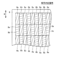
ここで、本実施形態では、表示パネル5を縦向きに配置した場合には、ドット領域5a〜5cおよび5e〜5gに表示される左目用画像L1および右目用画像R1は、階段状の一例である千鳥格子状(階段状)に配置されている。具体的には、図5に示した各ドット領域5a〜5cおよび5e〜5gにおいて、右目用画像R1の表示領域は、ハッチング(斜線)領域で示されており、左目用画像L1の表示領域は、ハッチング(斜線)が施されていない非ハッチング領域で示されている。図5に示すように、ハッチング領域に位置する左目用画像L1は、斜め方向(図5のC方向)にRGBのドット領域5a〜5cおよび5e〜5gが連続するように表示される。また、ハッチングのない非ハッチング領域に位置する右目用画像R1も、斜め方向(図5のC方向)にRGBのドット領域が連続するように表示される。そして、左目用画像L1と右目用画像R1とは、RGBのドット領域が連続するように延びる斜め方向(図5のC方向)に交差する方向に交互に表示される。
Here, in this embodiment, when the
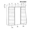
また、本実施形態では、表示パネル5を横向きに配置した場合には、図6に示すように、光の3原色(RGB)に対応するドット領域5a〜5cおよび5e〜5fは、それぞれ、観察者20(図3参照)の左目20aと右目20bとを結んだ線分に対して実質的に垂直方向(縦方向)(A方向)に延びるように配置される。また、ドット領域5a〜5cおよび5e〜5fの観察者20(図3参照)の左目20aと右目20bとを結んだ線分に沿った方向(横方向)(B方向)の長さは、横向き用液晶パネル4(図4参照)の偏光制御領域4aおよび4b(図4参照)の観察者20の左目20aと右目20bとを結んだ線分に沿った方向(縦方向)(B方向)の長さに対応するように設けられている。図6に示した横向き配置の場合には、ハッチング(斜線)領域で示される左目用画像L2、および、ハッチングの施されない非ハッチング領域で示される右目用画像R2は、それぞれ、縦方向(A方向)にRGBのドット領域5a〜5cおよび5e〜5gが連続して延びるように表示される。また、図6に示した横向き配置の場合には、縦方向(A方向)に延びる左目用画像L2と右目用画像R2とは、横方向(B方向)に交互に表示される。また、左目用画像L2が表示される領域(ハッチング領域)は、図3に示すように、横向き用液晶パネル4の偏光制御領域4bと観察者20の左目20aとを結んだ線上に配置されるとともに、横向き用液晶パネル4の偏光制御領域4aと観察者20の右目20bとを結んだ線上に配置される。また、右目用画像R2が表示される領域(非ハッチング領域)は、横向き用液晶パネル4の偏光制御領域4aと観察者20の左目20aとを結んだ線上に配置されるとともに、横向き用液晶パネル4の偏光制御領域4bと観察者20の右目20bとを結んだ線上に配置される。
Further, in the present embodiment, when the
また、偏光板7は、図1に示すように、観察者20側から見て約135°の偏光軸を有しているので、観察者20側から見て約135°の偏光軸を有する光のみを透過する機能を有する。また、位相差板8は、図7に示すように、複数の偏光制御領域8aおよび8bを含んでいる。なお、偏光制御領域8aは、本発明の「第1偏光制御領域」の一例であり、偏光制御領域8bは、本発明の「第2偏光制御領域」の一例である。また、偏光制御領域8aは、図2に示すように、表示パネル5の左目用画像L1が表示される領域と観察者20の右目20bとを結んだ線上に配置されるとともに、表示パネル5の右目用画像R1が表示される領域と観察者20の左目20aとを結んだ線上に配置される。また、偏光制御領域8bは、表示パネル5の左目用画像L1が表示される領域と観察者20の左目20aとを結んだ線上に配置されるとともに、表示パネル5の右目用画像R1が表示される領域と観察者20の右目20bとを結んだ線上に配置される。また、図7に示すように、偏光制御領域8aおよび8bは、図5に示した縦向きに配置した状態の表示パネル5のドット領域5a〜5cおよび5e〜5gに対応する実質的に長方形の形状を有する。また、表示パネル5(図5参照)を縦向きに配置した場合には、表示パネル5のドット領域5a〜5cおよび5e〜5gと同様、偏光制御領域8aおよび8bの長手方向が観察者20(図2参照)の左目20aと右目20b(図2参照)とを結んだ線分に対して実質的に垂直方向(B方向)に配置される。また、位相差板8の偏光制御領域8aおよび8bは、透過する光の偏光軸を位相差板8の偏光軸に対して線対称の偏光軸に変化させる機能を有する。
Further, as shown in FIG. 1, the
また、本実施形態では、位相差板8の偏光制御領域8aおよび8bは、図5および図7に示すように、表示パネル5の左目用画像L1および右目用画像R1の表示領域に対応するように千鳥格子状に配置されている。なお、本実施形態では、位相差板8の偏光制御領域8aおよび8bは、階段状の一例としての千鳥格子状に配置されている。また、図7に示すように、偏光制御領域8aは、観察者20(図2参照)側から見て約75°の偏光軸を有しており、偏光制御領域8bは、観察者20側から見て約15°の偏光軸を有している。
In the present embodiment, the
また、縦向き用液晶パネル9は、図1に示すように、観察者20側から見て約165°の偏光軸を有している。また、縦向き用液晶パネル9は、透過する光の偏光軸を縦向き用液晶パネル9の約165°の偏光軸に対して線対称の偏光軸に変化させる機能を有する。また、縦向き用液晶パネル9は、ON状態にすることによって約165°の偏光軸を無効にする機能を有するとともに、OFF状態にすることによって約165°の偏光軸を有効にする機能を有する。また、偏光板10は、観察者20側から見て約135°の偏光軸を有している。なお、偏光板10は、入射する光の偏光軸と偏光板10の偏光軸との交差する角度をθ、光量(光の振幅)をCとすると、入射する光を、観察者20側から見て約135°の偏光軸を有する光に変化させるとともに、C×(cosθ)2の光量(光の振幅)を有する光に変化させて透過する機能を有する。
Further, as shown in FIG. 1, the vertically oriented
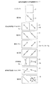
(縦向き配置時の立体画像表示モード)
図8は、図1に示した本発明の一実施形態による表示パネルの縦向き配置時における立体画像表示方法を説明するための図である。なお、図8において、破線は、偏光板3、6、7、10、横向き用液晶パネル4、位相差板8および縦向き用液晶パネル9の偏光軸の角度を示すとともに、矢印は、透過光の偏光軸の角度を示す。次に、図2、図4および図8を参照して、本発明の一実施形態による表示パネル5の縦向き配置時における立体画像表示方法について説明する。
(3D image display mode when placed vertically)
FIG. 8 is a diagram for explaining a stereoscopic image display method when the display panel according to the embodiment of the present invention shown in FIG. In FIG. 8, the broken lines indicate the angles of the polarization axes of the
まず、バックライト2(図2参照)から照射された光は、図8に示すように、偏光板3により、観察者20(図2参照)側から見て約135°の偏光軸を有する光のみを透過する。そして、観察者20側から見て約135°の偏光軸を有する光が、横向き用液晶パネル4の偏光制御領域4aおよび4bを透過する。この際、横向き用液晶パネル4の偏光制御領域4aおよび4bは、電極4c(図4参照)に電圧が印加されることにより、ON状態に制御されているので、横向き用液晶パネル4の偏光制御領域4aおよび4bの偏光軸は無効になっている。これにより、横向き用液晶パネル4の偏光制御領域4aおよび4bに入射した光は、偏光軸が変化されることなく透過する。その後、横向き用液晶パネル4を出射した光は、観察者20側から見て約135°の偏光軸を有する偏光板6を透過する。また、偏光板6を出射した光は、表示パネル5のドット領域5a〜5cおよび5e〜5gに入射する。この場合、図5に示すように、ドット領域5a〜5cおよび5e〜5gのうちのハッチング(斜線)領域には、左目用画像L1(図2参照)が表示されているとともに、ドット領域5a〜5cおよび5e〜5gのうちの非ハッチング領域には、右目用画像R1(図2参照)が表示されている。また、表示パネル5に入射した光は、図8に示すように、表示パネル5により偏光軸が90°変化した状態で出射される。すなわち、表示パネル5を透過した光は、偏光軸が観察者20(図2参照)側から見て約45°に変化された状態で出射される。そして、表示パネル5を出射した光は、観察者20側から見て約45°の偏光軸を有する偏光板7を透過する。また、偏光板7を透過した光は、位相差板8の偏光制御領域8aまたは8bに入射する。
First, the light emitted from the backlight 2 (see FIG. 2) is light having a polarization axis of about 135 ° as viewed from the observer 20 (see FIG. 2) side by the
また、本実施形態では、位相差板8に入射する光は観察者20(図2参照)側から見て約45°の偏光軸を有しているので、図8に示すように、位相差板8の偏光制御領域8aに入射した光は、位相差板8の偏光制御領域8aの約75°の偏光軸に対して線対称の偏光軸に変化されて透過する。すなわち、偏光制御領域8aを出射した光は、観察者20側から見て約105°の偏光軸を有する。そして、位相差板8の偏光制御領域8aを出射した光は、縦向き用液晶パネル9の約165°の偏光軸に対して線対称の偏光軸に変化されて透過する。すなわち、縦向き用液晶パネル9を出射した光は、観察者20側から見て約45°の偏光軸を有する。その後、縦向き用液晶パネル9を出射した光は、観察者20側から見て約135°の偏光軸を有する偏光板10により遮光される。この場合、位相差板8の偏光制御領域8aは、図2に示すように、表示パネル5の左目用画像L1が表示される領域と観察者20の右目20bとを結ぶ線上に配置されているので、左目用画像L1が観察者20の右目20bに入射するのを抑制することが可能となる。また、位相差板8の偏光制御領域8aは、表示パネル5の右目用画像R1が表示される領域と観察者20の左目20aとを結ぶ線上に配置されているので、右目用画像R1が観察者20の左目20aに入射するのを抑制することが可能となる。
In this embodiment, the light incident on the
一方、位相差板8の偏光制御領域8bに入射した光は、図8に示すように、位相差板8の偏光制御領域8bの約15°の偏光軸に対して線対称の偏光軸に変化されて透過する。すなわち、偏光制御領域8bを出射した光は、観察者20側から見て約165°の偏光軸を有する。そして、位相差板8の偏光制御領域8bを出射した光は、縦向き用液晶パネル9の約165°の偏光軸に対して線対称の偏光軸に変化されて透過する。この場合、位相差板8の偏光制御領域8bを出射した光の偏光軸の角度と縦向き用液晶パネル9の偏光軸の角度とが同じであるので、縦向き用液晶パネル9に入射した光は、偏光軸が約165°から変化されずに出射される。その後、縦向き用液晶パネル9を出射した光は、観察者20(図2参照)側から見て約135°の偏光軸に変化されるとともに、たとえば、光量(光の振幅)をDとすると、D×(cosθ1)2(θ1=約165°−約135°=約30°)の光量(光の振幅)を有する光に変化された状態で偏光板10から出射される。この場合、位相差板8の偏光制御領域8bは、図2に示すように、表示パネル5の左目用画像L1が表示される領域と、観察者20の左目20aとを結ぶ線上に配置されているので、左目用画像L1を観察者20の左目20aに入射することが可能となる。また、位相差板8の偏光制御領域8bは、表示パネル5の右目用画像R1が表示される領域と、観察者20の右目20bとを結ぶ線上に配置されているので、右目用画像R1を観察者20の右目20bに入射することが可能となる。
On the other hand, the light incident on the
上記のように、縦向き配置時において、観察者20の左目20aおよび右目20bに、それぞれ、左目用画像L1および右目用画像R1が入射されることにより、観察者20は、立体画像を見ることが可能となる。
As described above, the left eye image L1 and the right eye image R1 are incident on the
(横向き配置時の立体画像表示モード)
図9は、図1に示した本発明の一実施形態による表示パネルの横向き配置時における立体画像表示方法を説明するための図である。次に、図3、図4および図9を参照して、本発明の一実施形態による表示パネル5の縦向き配置時における立体画像表示方法について説明する。
(3D image display mode when placed in landscape orientation)
FIG. 9 is a view for explaining a stereoscopic image display method when the display panel shown in FIG. 1 according to the embodiment of the present invention is disposed horizontally. Next, with reference to FIG. 3, FIG. 4, and FIG. 9, a stereoscopic image display method when the
まず、バックライト2(図3参照)から照射された光は、図9に示すように、偏光板3により、観察者20(図3参照)側から見て約135°の偏光軸を有する光のみを透過する。なお、横向き配置時には、縦向き配置時に比べて偏光軸が90°ずつ回転するが、本実施形態では、簡略化のため、横向き配置時においても、縦向き配置時の偏光軸の角度をそのまま用いて説明する。そして、観察者20側から見て約135°の偏光軸を有する光が、横向き用液晶パネル4の偏光制御領域4aおよび4bを透過する。
First, the light emitted from the backlight 2 (see FIG. 3) is light having a polarization axis of about 135 ° when viewed from the observer 20 (see FIG. 3) side by the
また、横向き配置の場合には、横向き用液晶パネル4の偏光制御領域4aは、電極4c(図4参照)に電圧を印加しないOFF状態に制御されているので、横向き用液晶パネル4の偏光制御領域4aの水平方向(約0°)の偏光軸は有効になる。これにより、横向き用液晶パネル4の偏光制御領域4aに入射した光は、横向き用液晶パネル4の偏光制御領域4aの水平方向(約0°)の偏光軸に対して線対称の偏光軸に変化されて透過する。すなわち、偏光制御領域4aを出射した光は、観察者20側から見て約45°の偏光軸を有する。そして、横向き用液晶パネル4の偏光制御領域4aを出射した光は、観察者20側から見て約135°の偏光軸を有する偏光板6により遮光される。この場合、図3に示すように、横向き用液晶パネル4の偏光制御領域4aと観察者20の左目20aとを結ぶ線上に、表示パネル5の右目用画像R2が表示される領域が配置されているので、右目用画像R2が観察者20の左目20aに入射するのを抑制することが可能となる。また、横向き用液晶パネル4の偏光制御領域4aと観察者20の右目20bとを結ぶ線上に、表示パネル5の左目用画像L2が表示される領域が配置されているので、左目用画像L2が観察者20の右目20bに入射するのを抑制することが可能となる。
Further, in the case of the horizontal arrangement, the
一方、横向き用液晶パネル4の偏光制御領域4bは、横向き配置時には、電極4c(図4参照)に電圧を印加するON状態に制御されているので、横向き用液晶パネル4の偏光制御領域4bの偏光軸は無効になる。したがって、横向き用液晶パネル4の偏光制御領域4bに入射した光は、図9に示すように、偏光軸を変化されることなく出射される。すなわち、横向き用液晶パネル4の偏光制御領域4bから出射された光は、観察者20(図3参照)側から見て約135°の偏光軸を有する。
On the other hand, since the
また、横向き用液晶パネル4の偏光制御領域4bを出射した光は、観察者20(図3参照)側から見て約135°の偏光軸を有する偏光板6を透過する。また、偏光板6を出射した光は、表示パネル5のドット領域5a〜5cおよび5e〜5gに入射する。また、表示パネル5に入射した光は、表示パネル5により偏光軸が90°変化した状態で出射される。すなわち、表示パネル5を透過した光は、偏光軸が観察者20側から見て約45°に変化された状態で出射される。そして、表示パネル5を出射した光は、観察者20側から見て約45°の偏光軸を有する偏光板7を透過する。また、偏光板7を透過した光は、位相差板8の偏光制御領域8aまたは8bに入射する。
The light emitted from the
また、本実施形態では、位相差板8に入射する光は観察者20(図3参照)側から見て約45°の偏光軸を有しているので、位相差板8の偏光制御領域8aに入射した光は、位相差板8の偏光制御領域8aの約75°の偏光軸に対して線対称の偏光軸に変化されて透過する。すなわち、偏光制御領域8aを出射した光は、観察者20側から見て約105°の偏光軸を有する。また、縦向き用液晶パネル9は、ON状態に制御されるので、縦向き用液晶パネル9の偏光軸は無効になる。これにより、縦向き用液晶パネル9に入射した光は、偏光軸が変化されることなく縦向き用液晶パネル9から出射される。すなわち、縦向き用液晶パネル9を出射した光は、観察者20側から見て約105°の偏光軸を有する。その後、縦向き用液晶パネル9を出射した光は、観察者20側から見て約135°の偏光軸に変化されるとともに、たとえば、光量(光の振幅)をEとすると、E×(cosθ2)2(θ2=約135°−約105°=約30°)の光量(光の振幅)を有する光に変化された状態で偏光板10から出射される。このとき、図3に示すように、横向き用液晶パネル4の偏光制御領域4bと観察者20の左目20aとを結ぶ線上に、表示パネル5の左目用画像L2が表示される領域が配置されているので、左目用画像L2を観察者20の左目20aに入射することが可能となる。また、横向き用液晶パネル4の偏光制御領域4bと観察者20の右目20bとを結ぶ線上に、表示パネル5の右目用画像R2が表示される領域が配置されているので、右目用画像R2を観察者20の右目20bに入射することが可能となる。
Further, in the present embodiment, the light incident on the
一方、位相差板8の偏光制御領域8bに入射した光は、図9に示すように、位相差板8の偏光制御領域8bの約15°の偏光軸に対して線対称の偏光軸に変化されて透過する。すなわち、偏光制御領域8bを出射した光は、観察者20(図3参照)側から見て約165°の偏光軸を有する。また、縦向き用液晶パネル9は、ON状態に制御されるので、縦向き用液晶パネル9の偏光軸は無効になる。これにより、縦向き用液晶パネル9を出射した光は、偏光軸が変化されることなく縦向き用液晶パネル9から出射される。すなわち、縦向き用液晶パネル9を出射した光は、観察者20側から見て約165°の偏光軸を有する。その後、縦向き用液晶パネル9を出射した光は、観察者20側から見て約135°の偏光軸に変化されるとともに、たとえば、光量(光の振幅)をFとすると、F×(cosθ3)2(θ3=約165°−約135°=約30°)の光量(光の振幅)を有する光に変化された状態で偏光板10から出射される。このとき、図3に示すように、横向き用液晶パネル4の偏光制御領域4bと観察者20の左目20aとを結ぶ線上に、表示パネル5の左目用画像L2が表示される領域が配置されているので、左目用画像L2を観察者20の左目20aに入射することが可能となる。また、横向き用液晶パネル4の偏光制御領域4bと観察者20の右目20bとを結ぶ線上に、表示パネル5の右目用画像R2が表示される領域が配置されているので、右目用画像R2を観察者20の右目20bに入射することが可能となる。
On the other hand, as shown in FIG. 9, the light incident on the
上記のように、横向き配置時において、観察者20の左目20aおよび右目20bに、それぞれ、左目用画像L2および右目用画像R2が入射されることにより、観察者20は、立体画像を見ることが可能となる。
As described above, the left eye image L2 and the right eye image R2 are incident on the
(縦向き配置時の平面画像表示モード)
図10は、図1に示した本発明の一実施形態による表示パネルを縦向きに配置した場合の平面画像表示時において観察者が表示パネルを見た状態を上方から示した図である。図11は、図1に示した本発明の一実施形態による表示パネルの縦向き配置および横向き配置時における平面画像表示方法を説明するための図である。次に、図4、図10および図11を参照して、本発明の一実施形態による表示パネル5の縦向き配置時における平面画像表示方法について説明する。
(Plane image display mode when placed vertically)
FIG. 10 is a diagram showing a state in which an observer looks at the display panel from above when displaying a planar image when the display panel according to the embodiment of the present invention shown in FIG. 1 is arranged vertically. FIG. 11 is a diagram for explaining a planar image display method when the display panel shown in FIG. 1 according to the embodiment of the present invention is vertically arranged and horizontally arranged. Next, with reference to FIG. 4, FIG. 10, and FIG. 11, a planar image display method when the
まず、バックライト2(図10参照)から照射された光は、図11に示すように、偏光板3により、観察者20(図10参照)側から見て約135°の偏光軸を有する光のみを透過する。そして、観察者20側から見て約135°の偏光軸を有する光が、横向き用液晶パネル4の偏光制御領域4aおよび4bを透過する。この際、横向き用液晶パネル4の偏光制御領域4aおよび4bは、電極4c(図4参照)に電圧が印加されることにより、ON状態に制御されているので、横向き用液晶パネル4の偏光制御領域4aおよび4bの偏光軸は無効になっている。これにより、図11に示すように、横向き用液晶パネル4の偏光制御領域4aおよび4bに入射した光は、偏光軸が変化されることなく透過する。その後、横向き用液晶パネル4を出射した光は、観察者20側から見て約135°の偏光軸を有する偏光板6を透過する。また、偏光板6を出射した光は、表示パネル5のドット領域5a〜5cおよび5e〜5gに入射する。この場合、全てのドット領域5a〜5cおよび5e〜5g(図10参照)には、平面画像S1(図10参照)が表示されている。また、表示パネル5に入射した光は、表示パネル5により偏光軸が90°変化した状態で出射される。すなわち、表示パネル5を透過した光は、偏光軸が観察者20側から見て約45°に変化された状態で出射される。そして、表示パネル5を出射した光は、観察者20側から見て約45°の偏光軸を有する偏光板7を透過する。また、偏光板7を透過した光は、位相差板8の偏光制御領域8aまたは8bに入射する。
First, the light emitted from the backlight 2 (see FIG. 10) is light having a polarization axis of about 135 ° when viewed from the observer 20 (see FIG. 10) side by the
また、本実施形態では、位相差板8に入射する光は観察者20(図10参照)側から見て約45°の偏光軸を有しているので、位相差板8の偏光制御領域8aに入射した光は、位相差板8の偏光制御領域8aの約75°の偏光軸に対して線対称の偏光軸に変化されて透過する。すなわち、偏光制御領域8aを出射した光は、観察者20側から見て約105°の偏光軸を有する。また、縦向き用液晶パネル9は、ON状態に制御されるので、縦向き用液晶パネル9の偏光軸は無効になる。これにより、縦向き用液晶パネル9に入射した光は、偏光軸が変化されることなく縦向き用液晶パネル9から出射される。すなわち、縦向き用液晶パネル9を出射した光は、観察者20側から見て約105°の偏光軸を有する。その後、縦向き用液晶パネル9を出射した光は、観察者20側から見て約135°の偏光軸に変化されるとともに、たとえば、光量(光の振幅)をHとすると、H×(cosθ4)2(θ4=約135°−約105°=約30°)の光量(光の振幅)を有する光に変化された状態で偏光板10から出射される。この偏光制御領域8aを介して偏光板10から出射された光により、偏光制御領域8aに対応する表示パネル5の平面画像S1が観察者20の左目20aおよび右目20bに入射される。
In the present embodiment, the light incident on the
一方、位相差板8の偏光制御領域8bに入射した光は、図11に示すように、位相差板8の偏光制御領域8bの約15°の偏光軸に対して線対称の偏光軸に変化されて透過する。すなわち、偏光制御領域8bを出射した光は、観察者20(図10参照)側から見て約165°の偏光軸を有する。また、縦向き用液晶パネル9は、ON状態に制御されるので、縦向き用液晶パネル9の偏光軸は無効になる。これにより、縦向き用液晶パネル9を出射した光は、偏光軸が変化されることなく縦向き用液晶パネル9から出射される。すなわち、縦向き用液晶パネル9を出射した光は、観察者20側から見て約165°の偏光軸を有する。その後、縦向き用液晶パネル9を出射した光は、観察者20側から見て約135°の偏光軸に変化されるとともに、たとえば、光量(光の振幅)をIとすると、I×(cosθ5)2(θ5=約165°−約135°=約30°)の光量(光の振幅)を有する光に変化された状態で偏光板10から出射される。この偏光制御領域8bを介して偏光板10から出射された光により、偏光制御領域8bに対応する表示パネル5の平面画像S1が観察者20の左目20aおよび右目20bに入射される。
On the other hand, the light incident on the
上記のように、観察者20の左目20aおよび右目20bに平面画像S1が入射されることにより、観察者20は平面画像を見ることが可能となる。
As described above, when the planar image S1 is incident on the
(横向き配置時の平面画像表示モード)
図12は、図1に示した本発明の一実施形態による表示パネルを横向きに配置した場合の平面画像表示時において観察者が表示パネルを見た状態を上方から示した図である。次に、図4、図11および図12を参照して、本発明の一実施形態による表示パネル5の横向き配置時における平面画像表示方法について説明する。
(Plane image display mode when placed in landscape orientation)
FIG. 12 is a diagram showing a state in which an observer looks at the display panel from above when displaying a planar image when the display panel according to the embodiment of the present invention shown in FIG. 1 is arranged horizontally. Next, with reference to FIG. 4, FIG. 11, and FIG. 12, a planar image display method when the
まず、バックライト2(図12参照)から照射された光は、図11に示すように、偏光板3により、観察者20(図12参照)側から見て約135°の偏光軸を有する光のみを透過する。そして、観察者20側から見て約135°の偏光軸を有する光が、横向き用液晶パネル4の偏光制御領域4aおよび4bを透過する。この際、横向き用液晶パネル4の偏光制御領域4aおよび4bは、電極4c(図4参照)に電圧が印加されることにより、ON状態に制御されているので、横向き用液晶パネル4の偏光制御領域4aおよび4bの偏光軸は無効になっている。これにより、図11に示すように、横向き用液晶パネル4の偏光制御領域4aおよび4bに入射した光は、偏光軸が変化されることなく透過する。その後、横向き用液晶パネル4を出射した光は、観察者20側から見て約135°の偏光軸を有する偏光板6を透過する。また、偏光板6を出射した光は、表示パネル5のドット領域5a〜5cおよび5e〜5gに入射する。この場合、全てのドット領域5a〜5cおよび5e〜5g(図12参照)には、平面画像S2(図12参照)が表示されている。また、表示パネル5に入射した光は、表示パネル5により偏光軸が90°変化した状態で出射される。すなわち、表示パネル5を透過した光は、偏光軸が観察者20側から見て約45°に変化された状態で出射される。そして、表示パネル5を出射した光は、観察者20側から見て約45°の偏光軸を有する偏光板7を透過する。また、偏光板7を透過した光は、位相差板8の偏光制御領域8aまたは8bに入射する。
First, the light emitted from the backlight 2 (see FIG. 12) is light having a polarization axis of about 135 ° as viewed from the observer 20 (see FIG. 12) side by the
また、本実施形態では、位相差板8に入射する光は観察者20(図12参照)側から見て約45°の偏光軸を有しているので、位相差板8の偏光制御領域8aに入射した光は、位相差板8の偏光制御領域8aの約75°の偏光軸に対して線対称の偏光軸に変化されて透過する。すなわち、偏光制御領域8aを出射した光は、観察者20側から見て約105°の偏光軸を有する。また、縦向き用液晶パネル9は、ON状態に制御されるので、縦向き用液晶パネル9の偏光軸は無効になる。これにより、縦向き用液晶パネル9に入射した光は、偏光軸が変化されることなく縦向き用液晶パネル9から出射される。すなわち、縦向き用液晶パネル9を出射した光は、観察者20側から見て約105°の偏光軸を有する。その後、縦向き用液晶パネル9を出射した光は、観察者20側から見て約135°の偏光軸に変化されるとともに、たとえば、光量(光の振幅)をHとすると、H×(cosθ4)2(θ4=約135°−約105°=約30°)の光量(光の振幅)を有する光に変化された状態で偏光板10から出射される。この偏光制御領域8aを介して偏光板10から出射された光により、偏光制御領域8aに対応する表示パネル5の平面画像S2が観察者20の左目20aおよび右目20bに入射される。
In the present embodiment, the light incident on the
一方、位相差板8の偏光制御領域8bに入射した光は、図11に示すように、位相差板8の偏光制御領域8bの約15°の偏光軸に対して線対称の偏光軸に変化されて透過する。すなわち、偏光制御領域8bを出射した光は、観察者20(図12参照)側から見て約165°の偏光軸を有する。また、縦向き用液晶パネル9は、ON状態に制御されるので、縦向き用液晶パネル9の偏光軸は無効になる。これにより、縦向き用液晶パネル9を出射した光は、偏光軸が変化されることなく縦向き用液晶パネル9から出射される。すなわち、縦向き用液晶パネル9を出射した光は、観察者20側から見て約165°の偏光軸を有する。その後、縦向き用液晶パネル9を出射した光は、観察者20側から見て約135°の偏光軸に変化されるとともに、たとえば、光量(光の振幅)をIとすると、I×(cosθ5)2(θ5=約165°−約135°=約30°)の光量(光の振幅)を有する光に変化された状態で偏光板10から出射される。この偏光制御領域8bを介して偏光板10から出射された光により、偏光制御領域8bに対応する表示パネル5の平面画像S2が観察者20の左目20aおよび右目20bに入射される。
On the other hand, the light incident on the
上記のように、観察者20の左目20aおよび右目20bに平面画像S2が入射されることにより、観察者20は平面画像を見ることが可能となる。
As described above, when the planar image S2 is incident on the
(本実施形態の効果)
本実施形態では、上記のように、縦向き用の位相差板8と横向き用液晶パネル4とを設けるとともに、表示パネル5が縦向きに配置された状態で、位相差板8の偏光制御領域8bを透過した光により、左目用画像L1および右目用画像R1をそれぞれ観察者20の左目20aおよび右目20bに入射することにより、観察者20に立体画像を提供し、かつ、表示パネル5が横向きに配置された状態で、横向き用液晶4の偏光制御領域4bを透過した光により、左目用画像L2および右目用画像R2をそれぞれ観察者20の左目20aおよび右目20bに入射することにより、観察者20に立体画像を提供することによって、表示パネル5を縦向きに配置した場合および横向きに配置した場合の両方の場合に、観察者20に立体画像を提供することができる。
(Effect of this embodiment)
In the present embodiment, as described above, the polarization control region of the
また、本実施形態では、位相差板8に、複数の偏光制御領域8aおよび8bを設けるとともに、複数の偏光制御領域8aおよび8bを、表示パネル5が縦向きに配置された状態で、千鳥格子状に配置することによって、斜め方向に延びる千鳥格子状に配置された複数の偏光制御領域8aおよび8bにより、偏光制御領域8bを透過した光を縦方向および横方向にほぼ均等に分散した状態で観察者20の左目20aおよび右目20bに向かって進行させることができるので、表示パネル5の左目用画像L1および右目用画像R1の解像度の低下を縦方向と横方向とに分散することができる。これにより、画像劣化の少ない立体画像を観察者20に提供することができる。
In the present embodiment, the
また、本実施形態では、位相差板8の偏光制御領域8aおよび8bを、それぞれ、表示パネル5の各々のドット領域5a〜5cおよび5e〜5g毎に配置することによって、ドット領域5a〜5cおよび5e〜5g毎に設けられた偏光制御領域8aおよび8bにより、表示パネル5の左目用画像L1および右目用画像R1を細分化した状態で観察者20の左目20aおよび右目20bに入射させることができる。これにより、より画像劣化の少ない立体画像を観察者20に提供することができる。
In the present embodiment, the
また、本実施形態では、表示パネル5に、光の3原色をそれぞれ表示するためのドット領域5a〜5cおよび5e〜5gを設けるとともに、表示パネル5の光の3原色をそれぞれ表示するためのドット領域5a〜5cおよび5e〜5gを、表示パネル5が横向きに配置された状態で、観察者20の左目20aおよび右目20bを結んだ方向に対して実質的に垂直方向に隣接するように配置することによって、観察者20の左目20aおよび右目20bを結んだ方向に対して実質的に垂直に延びるように設けられた偏光制御領域4aおよび4bに対応するように光の3原色をそれぞれ表示するためのドット領域5a〜5cおよび5e〜5gを配置することができるので、偏光制御領域4aおよび4bに所定の1原色を表示するドット領域5a〜5cおよび5e〜5gのみを配置する場合に比べて、観察者20に画像劣化の少ない立体画像を提供することができる。
In the present embodiment, the
また、本実施形態では、位相差板8および横向き用液晶パネル4を、表示パネル5を挟み込むように配置することによって、表示パネル5と位相差板8との間隔W1(図13参照)を、たとえば、図14に示すように、表示パネル5および位相差板8を横向き用液晶パネル4を挟み込むように配置する場合の表示パネル5と位相差板8との間隔W2に比べて小さくすることができるので、表示パネル5からの適視距離W3(図13参照)を、表示パネル5および位相差板8を横向き用液晶パネル4を挟み込むように配置する場合の表示パネル5からの適視距離W4(図14参照)に比べて小さくすることができる。これにより、たとえば、画像表示装置1を表示パネル5が小さい携帯電話などに用いた場合に、表示パネル5から観察者20の左目20aおよび右目20bまでの距離を小さくすることができるので、表示パネル5の立体画像を見やすくすることができる。
In the present embodiment, the
なお、今回開示された実施形態は、すべての点で例示であって制限的なものではないと考えられるべきである。本発明の範囲は、上記した実施形態の説明ではなく特許請求の範囲によって示され、さらに特許請求の範囲と均等の意味および範囲内でのすべての偏光が含まれる。 The embodiment disclosed this time should be considered as illustrative in all points and not restrictive. The scope of the present invention is shown not by the above description of the embodiment but by the scope of claims for patent, and all polarizations within the scope and meaning equivalent to the scope of claims for patent are included.
たとえば、上記実施形態では、位相差板8の偏光制御領域8aおよび8bをドット領域毎に対応して設けるとともに、横向き用液晶パネル4の偏光制御領域4aおよび4bの幅をドット領域の幅に対応して設けた例を示したが、本発明はこれに限らず、位相差板8の偏光制御領域8aおよび8bを、たとえば、画素領域毎に対応して設けてもよいし、横向き用液晶パネル4の偏光制御領域4aおよび4bを複数のドット領域の幅に対応して設けてもよい。
For example, in the above embodiment, the
また、上記実施形態では、位相差板8の偏光制御領域8aおよび8bを階段状の一例である千鳥格子状に配置した例を示したが、本発明はこれに限らず、位相差板8の偏光制御領域8aおよび8bを所定の方向(図7のB方向)に延びるように配置してもよいし、千鳥格子状以外の階段状に延びるように配置してもよい。なお、上記実施形態において、複数の観察者に立体画像を提供する場合には、位相差板8の偏光制御領域8aおよび8bを千鳥格子状ではない階段状に延びるように配置すればよい。
In the above-described embodiment, the example in which the
また、上記実施形態では、横向き用液晶パネル4の偏光制御領域4aおよび4bを所定の方向に延びるように配置した例を示したが、本発明はこれに限らず、横向き用液晶パネル4の偏光制御領域4aおよび4bを、位相差板8の偏光制御領域8aおよび8bのように、千鳥格子状に配置してもよい。
In the above embodiment, the example in which the
また、上記実施形態では、表示パネルのドット領域を縦方向および横方向に直線的に配置した例を示したが、本発明はこれに限らず、図15に示した本発明の一実施形態の変形例のように、表示パネル15のドット領域15a〜15cを横方向に直線状に配置するとともに、ドット領域15d〜15fを横方向に直線状に配置し、ドット領域15a〜15cと、ドット領域15d〜15fとを縦方向に、それぞれ、ジグザグに配置してもよい。この場合、図16に示すように、位相差板18の偏光制御領域18aおよび18bを表示パネル15のドット領域15a〜15fに対応するように配置すればよい。たとえば、縦向きの配置状態で、立体画像を表示する場合には、図15のハッチング(斜線)領域に左目用画像L3を表示し、図15の非ハッチング領域に右目用画像R3を表示すればよい。この場合、図16の偏光制御領域18aおよび18bは、それぞれ、図15の左目用画像L3および右目用画像R3に対応するように配置すればよい。
Further, in the above embodiment, the example in which the dot areas of the display panel are linearly arranged in the vertical direction and the horizontal direction is shown, but the present invention is not limited to this, and the embodiment of the present invention shown in FIG. As in the modification, the
また、上記実施形態では、表示パネル5を挟み込むように配置される偏光板6および7は、互いに直交する偏光軸を有するTN(Twisted Nematic)方式を用いた例を示したが、本発明はこれに限らず、たとえば、VA(Vertical Alignment)方式およびECB(Electrically Controlled Birefringence)方式などの他の方式を用いてもよい。この場合、たとえば、VA方式を用いれば、表示パネル5を挟み込むように配置された偏光板6および7を、同じ偏光軸を有する偏光板により構成するとともに、表示パネル5、偏光板6および7の偏光軸に対応するように、偏光板3、横向き用液晶パネル4、位相差板8、縦向き用液晶パネル9および偏光板10の偏光軸を設定すればよい。
Further, in the above embodiment, the
また、上記実施形態では、偏光板3、6、7、10、横向き用液晶パネル4、位相差板8の偏光制御領域8a、8bおよび縦向き用液晶パネル9の偏光軸を、それぞれ、約135°、約135°、約45°、約135°、水平方向(約0°)、約75°、約15°、約165°に設定した例を示したが、本発明はこれに限らず、偏光板3、6、7、10、横向き用液晶パネル4、位相差板8の偏光制御領域8a、8bおよび縦向き用液晶パネル9の偏光軸を上記の値以外の値に設定してもよい。
In the above embodiment, the polarization axes of the
1 画像表示装置
2 バックライト(光源)
4 横向き用液晶パネル(第2偏光軸制御手段、第1偏光制御液晶パネル)
4a 偏光制御領域(第3偏光制御領域)
4b 偏光制御領域(第4偏光制御領域)
4c 電極
5 表示パネル
5a〜5c、5e〜5g ドット領域
5d、5h 画素領域
8 位相差板(第1偏光軸制御手段)
8a 偏光制御領域(第1偏光制御領域)
8b 偏光制御領域(第2偏光制御領域)
9 縦向き用液晶パネル(第3偏光軸制御手段、第2偏光制御液晶パネル)
1
4 Horizontally oriented liquid crystal panel (second polarization axis control means, first polarization control liquid crystal panel)
4a Polarization control region (third polarization control region)
4b Polarization control region (fourth polarization control region)
8a Polarization control region (first polarization control region)
8b Polarization control region (second polarization control region)
9 Vertical liquid crystal panel (third polarization axis control means, second polarization control liquid crystal panel)
Claims (12)
前記表示パネルに光を照射するための光源と、
前記光源から照射された光を第1の偏光軸を有する光と、第2の偏光軸を有する光とに分離するための第1偏光軸制御手段と、
前記光源から照射された光を第3の偏光軸を有する光と、第4の偏光軸を有する光とに分離するための第2偏光軸制御手段とを備え、
前記表示パネルが第1の方向に配置された状態で、前記第1の偏光軸を有する光および前記第2の偏光軸を有する光の一方を観察者の目に向かって進行させることにより、前記観察者に立体画像を提供するとともに、
前記表示パネルが前記第1の方向と交差する第2の方向に配置された状態で、前記第3の偏光軸を有する光および前記第4の偏光軸を有する光の一方を前記観察者の目に進行させることにより、前記観察者に立体画像を提供する、画像表示装置。 A display panel for displaying images;
A light source for irradiating the display panel with light;
First polarization axis control means for separating light emitted from the light source into light having a first polarization axis and light having a second polarization axis;
A second polarization axis control means for separating the light emitted from the light source into light having a third polarization axis and light having a fourth polarization axis;
In a state where the display panel is disposed in the first direction, by causing one of the light having the first polarization axis and the light having the second polarization axis to travel toward the eyes of the observer, While providing stereoscopic images to the observer,
With the display panel disposed in a second direction intersecting the first direction, one of the light having the third polarization axis and the light having the fourth polarization axis is viewed by the observer's eyes. An image display device that provides a three-dimensional image to the observer by proceeding to.
前記表示パネルが前記第1の方向と交差する前記第2の方向に配置された状態で、前記第3の偏光軸を有する光および前記第4の偏光軸を有する光の一方により、前記左目用画像を前記観察者の左目に向かって進行させるとともに、前記右目用画像を前記観察者の右目に向かって進行させることによって、前記観察者に立体画像を提供する、請求項1に記載の画像表示装置。 With the display panel arranged in the first direction, the left-eye image is directed toward the left eye of the observer by one of the light having the first polarization axis and the light having the second polarization axis. Providing a stereoscopic image to the observer by advancing the image for the right eye toward the right eye of the observer,
With the display panel disposed in the second direction intersecting the first direction, the left-eye-use light is generated by one of the light having the third polarization axis and the light having the fourth polarization axis. The image display according to claim 1, wherein the stereoscopic image is provided to the observer by causing the image to advance toward the left eye of the observer and the image for the right eye to advance toward the right eye of the observer. apparatus.
前記複数の第1偏光制御領域および前記複数の第2偏光制御領域は、前記表示パネルが第1の方向に配置された状態で、階段状に配置されている、請求項1または2に記載の画像表示装置。 The first polarization axis control means includes a plurality of first polarization control regions for controlling the light emitted from the light source to light having the first polarization axis, and the light emitted from the light source. A plurality of second polarization control regions for controlling light having two polarization axes,
3. The plurality of first polarization control regions and the plurality of second polarization control regions are arranged in a step shape in a state where the display panel is arranged in a first direction. Image display device.
前記第1偏光軸制御手段の前記第1偏光制御領域および前記第2偏光制御領域は、それぞれ、前記表示パネルの各々の前記ドット領域毎に配置されている、請求項3に記載の画像表示装置。 The display panel includes a plurality of dot regions for displaying the three primary colors of light,
The image display device according to claim 3, wherein the first polarization control region and the second polarization control region of the first polarization axis control unit are arranged for each of the dot regions of the display panel. .
前記第3偏光制御領域および前記第4偏光制御領域は、前記表示パネルが第2の方向に配置された状態で、前記観察者の左右の目を結んだ方向に対して実質的に垂直方向に延びるとともに、前記観察者の左右の目を結んだ方向に沿った方向に交互に配置されている、請求項1〜5のいずれか1項に記載の画像表示装置。 The second polarization axis control means includes a plurality of third polarization control regions for controlling the light emitted from the light source to light having the third polarization axis, and the light emitted from the light source. A plurality of fourth polarization control regions for controlling light having four polarization axes,
The third polarization control region and the fourth polarization control region are substantially perpendicular to the direction connecting the left and right eyes of the observer in a state where the display panel is arranged in the second direction. The image display device according to claim 1, wherein the image display device extends and alternately arranged in a direction along a direction connecting the left and right eyes of the observer.
前記第2偏光軸制御手段の前記第3偏光制御領域および前記第4偏光制御領域の前記観察者の左右の目を結んだ方向に沿った方向の長さは、前記ドット領域の前記観察者の左右の目を結んだ方向に沿った方向の長さに実質的に対応するように設定されており、
前記表示パネルの光の3原色をそれぞれ表示するための3つのドット領域は、前記表示パネルが第2の方向に配置された状態で、前記観察者の左右の目を結んだ方向に対して実質的に垂直方向に隣接するように配置される、請求項6に記載の画像表示装置。 The display panel includes three dot regions for displaying the three primary colors of light,
The length of the third polarization control region and the fourth polarization control region of the second polarization axis control unit in the direction along the direction connecting the left and right eyes of the observer is the length of the observer of the dot region. It is set to substantially correspond to the length in the direction along the direction connecting the left and right eyes,
The three dot areas for displaying the three primary colors of light of the display panel are substantially in the direction connecting the left and right eyes of the observer in a state where the display panel is arranged in the second direction. The image display device according to claim 6, wherein the image display devices are arranged adjacent to each other in the vertical direction.
前記第1偏光制御液晶パネルの前記第3偏光制御領域および前記第4偏光制御領域には、それぞれ、液晶に電圧を印加するための電極が前記第3偏光制御領域および前記第4偏光制御領域と同じ方向に延びるように形成されている、請求項6または7に記載の画像表示装置。 The second polarization axis control means includes a first polarization control liquid crystal panel having the third polarization control region and the fourth polarization control region,
The third polarization control region and the fourth polarization control region of the first polarization control liquid crystal panel have electrodes for applying a voltage to the liquid crystal, respectively, in the third polarization control region and the fourth polarization control region. The image display device according to claim 6, wherein the image display device is formed so as to extend in the same direction.
前記第2偏光軸制御手段は、前記第3の偏光軸を有する光および前記第4の偏光軸を有する光の一方を前記観察者の目に向かって進行させる場合と、前記第3の偏光軸を有する光および前記第4の偏光軸を有する光の両方を前記観察者の目に向かって進行させる場合とに切り換え可能であるとともに、
前記第3偏光軸制御手段は、前記第5の偏光軸を有する光および前記第6の偏光軸を有する光の一方を前記観察者の目に向かって進行させる場合と、前記第5の偏光軸を有する光および前記第6の偏光軸を有する光の両方を前記観察者の目に向かって進行させる場合とに切り換え可能であり、
前記第2偏光軸制御手段が、前記第3の偏光軸を有する光および前記第4の偏光軸を有する光の両方を前記観察者の目に向かって進行させるとともに、前記第3偏光軸制御手段が、前記第5の偏光軸を有する光および前記第6の偏光軸を有する光の両方を前記観察者の目に向かって進行させることによって、前記観察者に平面画像を提供する、請求項1〜11のいずれか1項に記載の画像表示装置。 Third polarization axis control means for controlling the light having the first polarization axis to the light having the fifth polarization axis and controlling the light having the second polarization axis to the light having the sixth polarization axis. Further comprising
The second polarization axis control means is configured to cause one of the light having the third polarization axis and the light having the fourth polarization axis to travel toward the eyes of the observer, and the third polarization axis. And can be switched between a case in which both the light having λ and the light having the fourth polarization axis travel toward the eyes of the observer,
The third polarization axis control means is configured to cause one of the light having the fifth polarization axis and the light having the sixth polarization axis to travel toward the eyes of the observer, and the fifth polarization axis. And when traveling both the light having the sixth polarization axis and the light having the sixth polarization axis to the observer's eyes,
The second polarization axis control means advances both the light having the third polarization axis and the light having the fourth polarization axis toward the eyes of the observer, and the third polarization axis control means. Providing a planar image to the observer by traveling both the light having the fifth polarization axis and the light having the sixth polarization axis toward the eyes of the observer. The image display apparatus of any one of -11.
Priority Applications (7)
| Application Number | Priority Date | Filing Date | Title |
|---|---|---|---|
| JP2005100407A JP2006284619A (en) | 2005-03-31 | 2005-03-31 | Image display apparatus |
| DE602006019795T DE602006019795D1 (en) | 2005-03-31 | 2006-03-15 | Image display device |
| EP06251372A EP1708516B1 (en) | 2005-03-31 | 2006-03-15 | Image display |
| CNB2006100659724A CN100561291C (en) | 2005-03-31 | 2006-03-29 | Image display device |
| TW095111155A TWI282440B (en) | 2005-03-31 | 2006-03-30 | Image display |
| KR1020060029482A KR100754081B1 (en) | 2005-03-31 | 2006-03-31 | Image display |
| US11/393,868 US7492514B2 (en) | 2005-03-31 | 2006-03-31 | Stereoscopic image display with vertical and lateral arrangements |
Applications Claiming Priority (1)
| Application Number | Priority Date | Filing Date | Title |
|---|---|---|---|
| JP2005100407A JP2006284619A (en) | 2005-03-31 | 2005-03-31 | Image display apparatus |
Publications (2)
| Publication Number | Publication Date |
|---|---|
| JP2006284619A true JP2006284619A (en) | 2006-10-19 |
| JP2006284619A5 JP2006284619A5 (en) | 2007-11-08 |
Family
ID=36480953
Family Applications (1)
| Application Number | Title | Priority Date | Filing Date |
|---|---|---|---|
| JP2005100407A Pending JP2006284619A (en) | 2005-03-31 | 2005-03-31 | Image display apparatus |
Country Status (7)
| Country | Link |
|---|---|
| US (1) | US7492514B2 (en) |
| EP (1) | EP1708516B1 (en) |
| JP (1) | JP2006284619A (en) |
| KR (1) | KR100754081B1 (en) |
| CN (1) | CN100561291C (en) |
| DE (1) | DE602006019795D1 (en) |
| TW (1) | TWI282440B (en) |
Cited By (3)
| Publication number | Priority date | Publication date | Assignee | Title |
|---|---|---|---|---|
| JP2010066511A (en) * | 2008-09-10 | 2010-03-25 | Pavonine Korea Inc | 3d-display device of non-eyeglass system |
| JP2010109414A (en) * | 2008-10-28 | 2010-05-13 | Seiko Epson Corp | Display device, electronic apparatus, and display method for parallax image data |
| WO2012046687A1 (en) * | 2010-10-04 | 2012-04-12 | シャープ株式会社 | Image display apparatus capable of displaying three-dimensional image, and display control device for controlling display of image |
Families Citing this family (15)
| Publication number | Priority date | Publication date | Assignee | Title |
|---|---|---|---|---|
| JP4111206B2 (en) * | 2005-05-31 | 2008-07-02 | エプソンイメージングデバイス株式会社 | Image display device |
| EP2268050A3 (en) * | 2005-05-31 | 2015-11-11 | Epson Imaging Devices Corporation | Image display |
| GB2437553A (en) * | 2006-04-28 | 2007-10-31 | Sharp Kk | Optical system with two spaced apart partial reflectors for display |
| KR100852758B1 (en) * | 2006-09-14 | 2008-08-18 | 한국과학기술연구원 | Image display system |
| TWI365302B (en) * | 2007-12-31 | 2012-06-01 | Ind Tech Res Inst | Stereo image display with switch function between horizontal display and vertical display |
| JP2011029161A (en) * | 2009-06-26 | 2011-02-10 | Sumitomo Chemical Co Ltd | Three-dimensional display device |
| TWI414975B (en) * | 2009-11-26 | 2013-11-11 | Ichia Tech Inc | Control panel and control method thereof |
| TWI422863B (en) * | 2009-12-23 | 2014-01-11 | Au Optronics Corp | Stereoscopic display |
| JP2011146797A (en) * | 2010-01-12 | 2011-07-28 | Sony Corp | Video display system |
| KR20130107265A (en) * | 2010-06-08 | 2013-10-01 | 리얼디 인크. | Stereoscopic liquid crystal display systems |
| WO2013053113A1 (en) * | 2011-10-12 | 2013-04-18 | Mediatek Inc. | Stereoscopic display apparatus and display method thereof |
| US9057880B2 (en) | 2011-11-30 | 2015-06-16 | Reald Inc. | Laser beam scanned display apparatus and method thereof |
| DE102012003789A1 (en) * | 2012-02-25 | 2013-08-29 | 3 D Graphics Gmbh | Monitor for stereoscopic 3D image display and associated operating method for a perceptual coding |
| CN104111538B (en) | 2014-07-08 | 2016-08-17 | 京东方科技集团股份有限公司 | Display device |
| US9594255B2 (en) * | 2015-06-25 | 2017-03-14 | Volfoni R&D EURL | Stereoscopic 3D projection system with improved level of optical light efficiency |
Citations (3)
| Publication number | Priority date | Publication date | Assignee | Title |
|---|---|---|---|---|
| JPH09159970A (en) * | 1995-12-07 | 1997-06-20 | Sanyo Electric Co Ltd | Method and device for displaying three-dimensional images in longitudinal direction and transverse direction |
| JP2004334550A (en) * | 2003-05-08 | 2004-11-25 | Sgi Japan Ltd | Method for processing three-dimensional image |
| JP2006018282A (en) * | 2004-06-29 | 2006-01-19 | Sharp Corp | 3-dimensional display capable of performing vertical display or horizontal display |
Family Cites Families (13)
| Publication number | Priority date | Publication date | Assignee | Title |
|---|---|---|---|---|
| JP2857429B2 (en) | 1989-10-02 | 1999-02-17 | 日本放送協会 | Three-dimensional image display apparatus and method |
| US5410345A (en) * | 1992-09-09 | 1995-04-25 | Dimension Technologies, Inc. | Stroboscopic illumination system for video displays |
| JP3229824B2 (en) * | 1995-11-15 | 2001-11-19 | 三洋電機株式会社 | 3D image display device |
| GB2317710A (en) * | 1996-09-27 | 1998-04-01 | Sharp Kk | Spatial light modulator and directional display |
| DE20022456U1 (en) * | 2000-01-25 | 2001-10-11 | 4D Vision Gmbh | Arrangement for displaying three-dimensionally perceptible image content |
| JP2002296540A (en) | 2001-03-29 | 2002-10-09 | Sanyo Electric Co Ltd | Stereoscopic image display device without spectacles |
| JP3940725B2 (en) | 2003-02-06 | 2007-07-04 | 株式会社東芝 | Stereoscopic image display device |
| KR100540109B1 (en) * | 2003-02-06 | 2006-01-10 | 가부시끼가이샤 도시바 | Stereoscopic image display apparatus |
| GB2403815A (en) * | 2003-07-10 | 2005-01-12 | Ocuity Ltd | Birefringent lens array structure |
| KR100561401B1 (en) * | 2003-07-28 | 2006-03-16 | 삼성전자주식회사 | Image displaying portion of 3D image system having multi viewing points interchangeable 2D and 3D images |
| KR100684715B1 (en) * | 2004-10-19 | 2007-02-20 | 삼성에스디아이 주식회사 | Stereoscopic image display and electronics with the same |
| KR100786862B1 (en) * | 2004-11-30 | 2007-12-20 | 삼성에스디아이 주식회사 | Barrier device, three dimensional image display using the same and method thereof |
| EP2268050A3 (en) * | 2005-05-31 | 2015-11-11 | Epson Imaging Devices Corporation | Image display |
-
2005
- 2005-03-31 JP JP2005100407A patent/JP2006284619A/en active Pending
-
2006
- 2006-03-15 DE DE602006019795T patent/DE602006019795D1/en active Active
- 2006-03-15 EP EP06251372A patent/EP1708516B1/en not_active Expired - Fee Related
- 2006-03-29 CN CNB2006100659724A patent/CN100561291C/en not_active Expired - Fee Related
- 2006-03-30 TW TW095111155A patent/TWI282440B/en not_active IP Right Cessation
- 2006-03-31 US US11/393,868 patent/US7492514B2/en not_active Expired - Fee Related
- 2006-03-31 KR KR1020060029482A patent/KR100754081B1/en active IP Right Grant
Patent Citations (3)
| Publication number | Priority date | Publication date | Assignee | Title |
|---|---|---|---|---|
| JPH09159970A (en) * | 1995-12-07 | 1997-06-20 | Sanyo Electric Co Ltd | Method and device for displaying three-dimensional images in longitudinal direction and transverse direction |
| JP2004334550A (en) * | 2003-05-08 | 2004-11-25 | Sgi Japan Ltd | Method for processing three-dimensional image |
| JP2006018282A (en) * | 2004-06-29 | 2006-01-19 | Sharp Corp | 3-dimensional display capable of performing vertical display or horizontal display |
Cited By (3)
| Publication number | Priority date | Publication date | Assignee | Title |
|---|---|---|---|---|
| JP2010066511A (en) * | 2008-09-10 | 2010-03-25 | Pavonine Korea Inc | 3d-display device of non-eyeglass system |
| JP2010109414A (en) * | 2008-10-28 | 2010-05-13 | Seiko Epson Corp | Display device, electronic apparatus, and display method for parallax image data |
| WO2012046687A1 (en) * | 2010-10-04 | 2012-04-12 | シャープ株式会社 | Image display apparatus capable of displaying three-dimensional image, and display control device for controlling display of image |
Also Published As
| Publication number | Publication date |
|---|---|
| CN100561291C (en) | 2009-11-18 |
| US7492514B2 (en) | 2009-02-17 |
| US20060227256A1 (en) | 2006-10-12 |
| DE602006019795D1 (en) | 2011-03-10 |
| TW200634341A (en) | 2006-10-01 |
| CN1841127A (en) | 2006-10-04 |
| KR20060105645A (en) | 2006-10-11 |
| EP1708516A1 (en) | 2006-10-04 |
| KR100754081B1 (en) | 2007-08-31 |
| EP1708516B1 (en) | 2011-01-26 |
| TWI282440B (en) | 2007-06-11 |
Similar Documents
| Publication | Publication Date | Title |
|---|---|---|
| JP2006284619A (en) | Image display apparatus | |
| JP4765389B2 (en) | Image display device | |
| KR100813744B1 (en) | Image display | |
| TWI480588B (en) | Display device | |
| JP4386040B2 (en) | Electro-optical device and electronic apparatus | |
| JP4765434B2 (en) | Image display device | |
| KR20130012011A (en) | Liquid crystal grating module and two dimension-three dimension switchable liquid crystal display device using the same | |
| JP4841868B2 (en) | Image display device | |
| JP4935045B2 (en) | Image display device | |
| JP4483181B2 (en) | 3D image display device | |
| JP2012226104A (en) | Display device | |
| WO2005054930A1 (en) | Display panel and display device | |
| WO2014015606A1 (en) | 3d display device and manufacturing method therefor | |
| JP4111206B2 (en) | Image display device | |
| US9658483B2 (en) | Liquid crystal lens and display including the same | |
| JP4894314B2 (en) | Image display device | |
| JP4844575B2 (en) | Image display method | |
| KR20150004028A (en) | 3 dimensional stereography image displayable device | |
| JP2005172925A (en) | Device and method to display stereoscopic image | |
| JP2006337866A (en) | Picture display device | |
| JP2006337494A (en) | Picture display device | |
| JP2003066370A (en) | Three-dimensional display device | |
| KR20120086275A (en) | A stereoscopic image display device | |
| JP2012203111A (en) | Stereoscopic image display device | |
| JP2007121720A (en) | Display apparatus |
Legal Events
| Date | Code | Title | Description |
|---|---|---|---|
| A521 | Request for written amendment filed |
Free format text: JAPANESE INTERMEDIATE CODE: A523 Effective date: 20070921 |
|
| A621 | Written request for application examination |
Free format text: JAPANESE INTERMEDIATE CODE: A621 Effective date: 20070921 |
|
| A131 | Notification of reasons for refusal |
Free format text: JAPANESE INTERMEDIATE CODE: A131 Effective date: 20100831 |
|
| A977 | Report on retrieval |
Free format text: JAPANESE INTERMEDIATE CODE: A971007 Effective date: 20100831 |
|
| A521 | Request for written amendment filed |
Free format text: JAPANESE INTERMEDIATE CODE: A523 Effective date: 20101028 |
|
| A02 | Decision of refusal |
Free format text: JAPANESE INTERMEDIATE CODE: A02 Effective date: 20101207 |