JP2006258604A - Detection device - Google Patents
Detection device Download PDFInfo
- Publication number
- JP2006258604A JP2006258604A JP2005076357A JP2005076357A JP2006258604A JP 2006258604 A JP2006258604 A JP 2006258604A JP 2005076357 A JP2005076357 A JP 2005076357A JP 2005076357 A JP2005076357 A JP 2005076357A JP 2006258604 A JP2006258604 A JP 2006258604A
- Authority
- JP
- Japan
- Prior art keywords
- scan
- obstacle
- detection device
- traveling direction
- traveling
- Prior art date
- Legal status (The legal status is an assumption and is not a legal conclusion. Google has not performed a legal analysis and makes no representation as to the accuracy of the status listed.)
- Pending
Links
Images


Classifications
-
- G—PHYSICS
- G01—MEASURING; TESTING
- G01C—MEASURING DISTANCES, LEVELS OR BEARINGS; SURVEYING; NAVIGATION; GYROSCOPIC INSTRUMENTS; PHOTOGRAMMETRY OR VIDEOGRAMMETRY
- G01C3/00—Measuring distances in line of sight; Optical rangefinders
- G01C3/02—Details
- G01C3/06—Use of electric means to obtain final indication
- G01C3/08—Use of electric radiation detectors
-
- G—PHYSICS
- G01—MEASURING; TESTING
- G01S—RADIO DIRECTION-FINDING; RADIO NAVIGATION; DETERMINING DISTANCE OR VELOCITY BY USE OF RADIO WAVES; LOCATING OR PRESENCE-DETECTING BY USE OF THE REFLECTION OR RERADIATION OF RADIO WAVES; ANALOGOUS ARRANGEMENTS USING OTHER WAVES
- G01S17/00—Systems using the reflection or reradiation of electromagnetic waves other than radio waves, e.g. lidar systems
- G01S17/02—Systems using the reflection of electromagnetic waves other than radio waves
- G01S17/06—Systems determining position data of a target
- G01S17/46—Indirect determination of position data
-
- G—PHYSICS
- G01—MEASURING; TESTING
- G01S—RADIO DIRECTION-FINDING; RADIO NAVIGATION; DETERMINING DISTANCE OR VELOCITY BY USE OF RADIO WAVES; LOCATING OR PRESENCE-DETECTING BY USE OF THE REFLECTION OR RERADIATION OF RADIO WAVES; ANALOGOUS ARRANGEMENTS USING OTHER WAVES
- G01S17/00—Systems using the reflection or reradiation of electromagnetic waves other than radio waves, e.g. lidar systems
- G01S17/88—Lidar systems specially adapted for specific applications
- G01S17/93—Lidar systems specially adapted for specific applications for anti-collision purposes
- G01S17/931—Lidar systems specially adapted for specific applications for anti-collision purposes of land vehicles
Abstract
Description
本発明は、レーザ光を目標領域に照射して目標領域内の障害物を検出する検出装置に関し、たとえば、自動車や飛行機等の移動体に搭載して好適なものである。 The present invention relates to a detection device that detects an obstacle in a target region by irradiating the target region with laser light, and is suitable for mounting on a moving body such as an automobile or an airplane.
近年、走行時の安全性を高めるために、目標領域にレーザ光を照射して走行方向前方の障害物を検出する検出装置が家庭用乗用車等に搭載されている。かかる検出装置は、レーザ光を目標領域内にてスキャンさせ、その反射光の有無から目標領域内の障害物を検出する。通常走行時には、走行方向前方に設定された目標領域をレーザ光がくまなくスキャンするようなスキャンパターンが設定される。各スキャン位置においてパルス光を出力し、その反射光を光検出器が受光するかによって、そのスキャン位置における障害物の有無を検出する。このとき同時に、パルス光の出力タイミングから反射光の受光タイミングまでの時間をもとに障害物までの距離が測定される。 In recent years, in order to improve safety during traveling, a detection device that detects an obstacle ahead of the traveling direction by irradiating a target region with laser light is mounted on a domestic passenger car or the like. Such a detection device scans the laser beam in the target area and detects an obstacle in the target area from the presence or absence of the reflected light. During normal running, a scan pattern is set such that the laser beam scans all over the target area set in front of the running direction. Pulse light is output at each scan position, and the presence or absence of an obstacle at the scan position is detected depending on whether the photodetector receives the reflected light. At the same time, the distance to the obstacle is measured based on the time from the pulse light output timing to the reflected light reception timing.
なお、以下の特許文献1には、加速度センサーを用いて走行方向とレーザ光の照射方向のズレを検出し、レーザ光の照射方向を走行方向に向けるように調整する技術が記載されている。
かかる検出装置においては、たとえば走行方向が右旋回あるいは左旋回に変化するような場合、特に、これから旋回しようとする方向の障害物をいち早く検出して次の走行制御の適正化を図るのが重要となる。また、高速走行時においては、走行方向遠方の障害物をいち早く検出して走行制御に反映するのが重要となる。さらに、走行方向前方に障害物を検出した場合には、特に、その障害物がどのような動き、状態にあるのかを細かく監視する必要がある。 In such a detection device, for example, when the traveling direction changes to a right turn or a left turn, an obstacle in the direction in which the vehicle is going to turn can be detected quickly to optimize the next traveling control. It becomes important. Also, when traveling at high speed, it is important to quickly detect obstacles far away in the traveling direction and reflect them in the traveling control. Furthermore, when an obstacle is detected in front of the traveling direction, it is necessary to monitor in detail how the obstacle moves and is in a state.
上記特許文献1には、レーザ光の照射方向を走行方向に向けるように調整する技術が記載されているものの、高速走行時や障害物検出時におけるスキャン制御については記載されておらず、また、走行方向変化時においても、単に、レーザ光の照射方向を走行方向に向けるように調整することが記載されるに留まっている。
Although the technique for adjusting the laser light irradiation direction to the traveling direction is described in
そこで、本発明は、スキャン制御の適正化を図ることにより、走行方向変化時、高速走行時および障害物検出時において障害物の動きや状態を精度よく検出できる検出装置を提供することを課題とする。 SUMMARY OF THE INVENTION It is an object of the present invention to provide a detection device capable of accurately detecting the movement and state of an obstacle when changing the traveling direction, when traveling at a high speed, and when detecting an obstacle by optimizing scan control. To do.
上記課題に鑑み本発明は、以下の特徴を有する。 In view of the above problems, the present invention has the following features.
請求項1の発明は、レーザ光を目標領域に照射して前記目標領域内の障害物を検出する検出装置において、前記レーザ光のスキャン軌跡を該検出装置が搭載される移動体の移動状態に関する信号に基づいて制御するスキャン制御手段を有することを特徴とする。 According to a first aspect of the present invention, there is provided a detection device for irradiating a target region with laser light to detect an obstacle in the target region, wherein the scan locus of the laser light is related to a moving state of a moving body on which the detection device is mounted. It has a scan control means which controls based on a signal.
請求項2の発明は、請求項1に記載の検出装置において、前記スキャン制御手段は、前記移動体の進行方向および/もしくは進行速度に関する信号に基づいて、前記レーザ光のスキャン軌跡を設定することを特徴とする。 According to a second aspect of the present invention, in the detection apparatus according to the first aspect, the scan control means sets a scan locus of the laser beam based on a signal relating to a traveling direction and / or a traveling speed of the moving body. It is characterized by.
請求項3の発明は、請求項2に記載の検出装置において、前記スキャン制御手段は、前記移動体の進行方向に関する信号に基づいて、前記レーザ光のスキャン軌跡を、前記進行方向の中心軸から前記進行方向の変化方向に偏った部分のスキャン頻度が高められるスキャン軌跡に設定することを特徴とする。 According to a third aspect of the present invention, in the detection device according to the second aspect, the scan control means is configured to determine the scan locus of the laser beam from the central axis in the traveling direction based on a signal related to the traveling direction of the moving body. The scanning trajectory is set so as to increase the scanning frequency of the portion biased in the changing direction of the traveling direction.
請求項4の発明は、請求項3に記載の検出装置において、前記スキャン制御手段は、前記移動体の進行方向に関する信号に基づいて、前記目標領域を、前記進行方向の中心軸から前記進行方向の変化方向にシフトさせることを特徴とする。 According to a fourth aspect of the present invention, in the detection device according to the third aspect, the scan control means moves the target region from the central axis of the traveling direction to the traveling direction based on a signal related to the traveling direction of the moving body. It is characterized by shifting in the change direction.
請求項5の発明は、請求項3または4に記載の検出装置において、前記スキャン制御手段は、前記移動体の進行方向に関する信号に基づいて、前記目標領域内における前記レーザ光のスキャンパターンを、前記目標領域の中心部から前記進行方向の変化方向に偏った部分のスキャン頻度が高められるスキャンパターンに設定することを特徴とする。 According to a fifth aspect of the present invention, in the detection device according to the third or fourth aspect, the scan control unit is configured to calculate a scan pattern of the laser light in the target area based on a signal related to a traveling direction of the moving body. The scan pattern is set so that the scan frequency of a portion deviated from the center of the target region in the direction of change of the traveling direction is increased.
請求項6の発明は、請求項2に記載の検出装置において、前記スキャン制御手段は、前記移動体の進行速度に関する信号に基づいて、前記レーザ光のスキャン軌跡を、前記進行方向の中心部分のスキャン頻度が高められるスキャン軌跡に設定することを特徴とする。 According to a sixth aspect of the present invention, in the detection device according to the second aspect, the scan control means determines the scan locus of the laser light at the central portion in the traveling direction based on a signal related to the traveling speed of the moving body. The scan trajectory is set so as to increase the scan frequency.
請求項7の発明は、請求項6に記載の検出装置において、前記スキャン制御手段は、前記移動体の進行速度に関する信号に基づいて、前記目標領域を、前記進行方向の中心部分に向けて縮小させることを特徴とする。 According to a seventh aspect of the present invention, in the detection device according to the sixth aspect, the scan control means reduces the target area toward a central portion in the traveling direction based on a signal related to the traveling speed of the moving body. It is characterized by making it.
請求項8の発明は、請求項6または7に記載の検出装置において、前記スキャン制御手段は、前記移動体の進行速度に関する信号に基づいて、前記目標領域内における前記レーザ光のスキャンパターンを、前記目標領域の中心部分のスキャン頻度が高められるスキャンパターンに設定することを特徴とする。
The invention according to
請求項9の発明は、レーザ光を目標領域に照射して前記目標領域内の障害物を検出する検出装置において、前記レーザ光のスキャン軌跡を前記障害物の検出結果に基づいて制御するスキャン制御手段を有することを特徴とする。 According to a ninth aspect of the present invention, there is provided a detection apparatus for irradiating a target area with laser light to detect an obstacle in the target area, wherein the scan control for controlling the scan locus of the laser light based on the detection result of the obstacle is provided. It has the means.
請求項10の発明は、請求項9に記載の検出装置において、前記スキャン制御手段は、前記障害物の検出結果に基づいて、前記レーザ光のスキャン軌跡を、前記障害物近傍のスキャン頻度が高められるスキャン軌跡に設定することを特徴とする。 According to a tenth aspect of the present invention, in the detection device according to the ninth aspect, the scan control means increases the scan trajectory of the laser light based on the detection result of the obstacle, and the scan frequency near the obstacle is increased. It is characterized in that it is set to a scan trajectory to be generated.
請求項11の発明は、請求項10に記載の検出装置において、前記スキャン制御手段は、前記障害物の検出結果に基づいて、前記スキャン軌跡の原点を前記障害物の検出位置に設定し、前記目標領域内における前記レーザ光のスキャンパターンを、前記設定された原点に反復回帰するスキャンパターンに設定することを特徴とする。 According to an eleventh aspect of the present invention, in the detection device according to the tenth aspect, the scan control unit sets an origin of the scan locus to a detection position of the obstacle based on a detection result of the obstacle, The scan pattern of the laser beam in the target area is set to a scan pattern that repeatedly returns to the set origin.
請求項12の発明は、請求項9ないし11の何れかに記載の検出装置において、前記スキャン制御手段は、前記障害物との距離が閾値距離よりも小さいときに、前記レーザ光のスキャン軌跡を前記障害物近傍のスキャン頻度が高められるスキャン軌跡に設定することを特徴とする。 The invention according to a twelfth aspect is the detection device according to any one of the ninth to eleventh aspects, wherein the scan control means displays a scan locus of the laser beam when a distance from the obstacle is smaller than a threshold distance. The scanning trajectory is set so as to increase the scanning frequency near the obstacle.
請求項1ないし8の発明によれば、走行方向変化時および高速走行時にスキャン軌跡の適正化が図られる。これにより、走行方向変化方向および走行方向遠方の障害物を精度よく検出することができる。 According to the first to eighth aspects of the invention, it is possible to optimize the scan trajectory when the traveling direction is changed and when traveling at a high speed. Thereby, the obstacle of the traveling direction change direction and the traveling direction far away can be detected with high accuracy.
すなわち、請求項3ないし5の発明によれば、走行方向中心軸から走行方向の変化方向に偏った部分のスキャン頻度が高められるため、走行方向の変化方向にある障害物をいち早く検出することができる。また請求項6ないし8の発明によれば、走行方向中心部分のスキャン頻度が高められるため、走行方向遠方の障害物をいち早く検出することができる。 That is, according to the third to fifth aspects of the invention, since the scan frequency of the portion deviated from the traveling direction central axis in the traveling direction change direction is increased, it is possible to quickly detect an obstacle in the traveling direction change direction. it can. Further, according to the sixth to eighth aspects of the invention, since the scanning frequency of the central portion in the traveling direction is increased, an obstacle far away in the traveling direction can be detected quickly.
請求項9ないし12の発明によれば、障害物検出時にスキャン軌跡の適正化が図られる。これにより、障害物の動きや状態を精度よく検出することができる。 According to the ninth to twelfth aspects of the present invention, the scan trajectory is optimized when an obstacle is detected. Thereby, the movement and state of the obstacle can be accurately detected.
すなわち、請求項10および11の発明によれば、障害物近傍のスキャン頻度が高められるため、障害物の動きや状態を細かく検出することができる。また、請求項12の発明によれば、障害物が接近しているときにのみ障害物近傍のスキャン頻度が高められ、障害物が未だ遠方にあり障害物の動きや状態を細かく検出する必要がないときは障害物近傍のスキャン頻度は高められない。よって、不必要な障害物の監視を回避でき、スキャン制御の適正化を図ることができる。
That is, according to the tenth and eleventh aspects of the invention, since the scan frequency near the obstacle is increased, the movement and state of the obstacle can be detected in detail. According to the invention of
本発明の特徴は、以下に示す実施形態の説明により更に明らかとなろう。ただし、以下に示す実施形態は、あくまでも実施形態の例示であって、これにより本発明ないし各構成要件の用語の意義が制限されるものではない。
The features of the present invention will become more apparent from the following description of embodiments. However, the embodiment described below is merely an example of the embodiment, and the meaning of the terms of the present invention or each constituent element is not limited thereby.
以下、本発明の実施の形態につき図面を参照して説明する。なお、本実施の形態は、自動車に搭載されるビーム照射装置に本発明を適用したものである。本実施の形態では、自動車前方からビームがスキャン照射されることにより、スキャン領域内の障害物の有無と、障害物までの距離が測定される。 Embodiments of the present invention will be described below with reference to the drawings. In the present embodiment, the present invention is applied to a beam irradiation apparatus mounted on an automobile. In the present embodiment, the beam is scanned from the front of the automobile, and the presence / absence of an obstacle in the scan area and the distance to the obstacle are measured.
図1に実施の形態に係るビーム照射装置の構成を示す。 FIG. 1 shows a configuration of a beam irradiation apparatus according to the embodiment.
図示の如く、ビーム照射装置は、DSP(Digital Signal Processor)制御回路10と、DAC(Digital Analog Converter)20と、レーザ駆動回路30と、アクチュエータ駆動回路40と、ビーム照射ヘッド50と、PSD(Position Sensitive Detector)信号処理回路60と、ADC(Analog Digital Converter)70と、PD(Photo Detector)信号処理回路80と、ADC90を備えている。
As shown, the beam irradiation apparatus includes a DSP (Digital Signal Processor)
DSP制御回路10は、レーザ駆動回路30およびアクチュエータ駆動回路40を駆動制御するためのデジタル信号をDAC20に出力する。また、ADC90から入力されるデジタル信号をもとに、スキャン領域内に含まれる障害物の位置と障害物までの距離を検出する。DSP制御回路10には、スキャン制御ルーチン10aと距離測定ルーチン10bが配備されている。
The
このうち、スキャン制御ルーチン10aには、自動車の操舵方向と速度に関する信号が外部信号として入力され、また、距離測定ルーチン10bによって検出された障害物の位置と障害物までの距離に関する信号が入力される。スキャン制御ルーチンは、これらの信号をもとに、スキャンパターンないしスキャン領域を変更する。スキャン制御ルーチンにおけるスキャン制御については、追って詳述する。
Of these, signals relating to the steering direction and speed of the vehicle are input as external signals to the
距離測定ルーチン10bには、高周波の内部クロックが入力されている。距離測定ルーチンは、各スキャン位置において出力されるパルス光の出力タイミングからその反射光の受光タイミングまでのクロック数Nをカウントする。そして、カウントしたクロック数Nをもとに、当該スキャン位置における障害物の有無と障害物までの距離Lを検出する。たとえば、内部クロックの周期をTとして、L=C(光速)×T×N/2を演算することにより障害物までの距離を検出する。なお、予め決められた時間内に反射光を受光できない場合は、当該スキャン位置には障害物が存在しないとされる。
A high-frequency internal clock is input to the
DAC20は、DSP制御回路10から入力されたデジタル信号をアナログ信号(制御信号)に変換してレーザ駆動回路30およびアクチュエータ駆動回路40に出力する。レーザ駆動回路30は、DAC20から入力された制御信号に応じて、ビーム照射ヘッド50内の半導体レーザ100を駆動する。アクチュエータ駆動回路40は、DAC20から入力された制御信号に応じて、ビーム照射ヘッド50内のレンズアクチュエータ300を駆動する。
The
ビーム照射ヘッド50は、前方空間に設定された目標領域にレーザ光をスキャンさせながら照射する。図示の如く、ビーム照射ヘッド50は、半導体レーザ100と、アパーチャ200と、レンズアクチュエータ300と、ビームスプリッタ400と、集光レンズ500と、PSD600と、受光レンズ700と光検出器800を備えている。
The beam irradiation head 50 irradiates the target area set in the front space while scanning the laser beam. As illustrated, the beam irradiation head 50 includes a
半導体レーザ100から出射されたレーザ光は、アパーチャ200によって所望の形状に整形された後、レンズアクチュエータ300に支持された照射レンズに入射される。ここで、照射レンズは、同図のY−Z平面方向に変位可能となるよう、レンズアクチュエータ300によって支持されている。したがって、照射レンズを通過したレーザ光は、レンズアクチュエータ300の駆動に応じて、Y−Z平面方向に出射角度が変化する。これにより、目標領域におけるレーザ光のスキャンが行われる。
Laser light emitted from the
照射レンズを通過したレーザ光は、ビームスプリッタ400によってその一部が反射され、照射レーザ光(目標領域に照射されるレーザ光)から分離される。分離されたレーザ光(分離光)は、集光レンズ500を通してPSD600上に収束される。PSD600は、同図のX−Y平面に平行な受光面を有しており、この受光面上における分離光の収束位置に応じた電流を出力する。ここで、受光面上における分離光の収束位置と目標領域上における前記照射レーザ光の照射位置は一対一に対応している。よって、PSD60から出力される電流は、目標領域上における前記照射レーザ光の照射位置に対応するものとなっている。なお、PSD600の構成および電流の出力動作については、図4、図5を参照しながら追って詳述する。
Part of the laser light that has passed through the irradiation lens is reflected by the
PSD600からの出力電流はPSD信号処理回路60に入力される。PSD信号処理回路60は、入力された電流から分離光の収束位置を表す電圧信号をADC70に出力する。ADC70は、入力された電圧信号をデジタル信号に変換してDSP制御回路10に出力する。かかる電圧信号はDSP制御回路10内のスキャン制御ルーチン10aに入力される。スキャン制御ルーチン10aは、入力された電圧信号をもとに、受光面上における分離光の収束位置を検出する。
The output current from the
なお、DSP制御回路10には、レーザ光の照射位置を目標領域内においてスキャンさせるためのテーブル(スキャンテーブル)と、このテーブルに従ってレーザ光をスキャンさせたときの、受光面上における分離光の収束位置の軌道を示すテーブル(軌道テーブル)が配備されている。
The
スキャン制御ルーチン10aは、レーザ光のスキャン動作時、スキャンテーブルを参照しながらアクチュエータ駆動回路40を制御するための信号をDAC20に出力する。また、同時に、ADC70から入力された信号をもとに受光面上における分離光の収束位置を検出し、検出した位置と軌道テーブルにて規定された所期の収束位置とを比較して、検出位置が所期の収束位置に引き込まれるよう、アクチュエータ駆動回路40を制御するための信号をDAC20に出力する。かかるサーボ動作によって、照射レーザ光は、スキャンテーブルにて規定された軌道に沿うよう目標領域内をスキャンする。なお、サーボ動作の詳細は、図7を参照しながら追って詳述する。
The
さらに、スキャン制御ルーチン10aは、レーザ光のスキャン動作時、半導体レーザ100の出射パワーを低レベルPwaに設定するための信号を、DAC20を介してレーザ駆動回路30に出力する。また、これと同時に、受光面上における分離光の収束位置を監視し、この収束位置が、障害物検出や距離検出等を行うための位置(発光点)として予め設定され位置に到達したタイミングにて、半導体レーザ100の出射パワーを一定期間だけパルス状に高レベルPwbに設定するための信号を、DAC20を介してレーザ駆動回路30に出力する。ここで、パワーPwaは、少なくとも、上記受光面上における分離光の位置検出を行える程度の電流がPSD600から出力される程度のものとなるようなパワーに設定される。また、パワーPwbは、所期の障害物検出や距離検出等を行うに十分なパワーに設定される。しかして、照射レーザ光は、目標領域内を低パワーにてスキャンしながら、発光点に到達したタイミングにて高パワーに発光する。
Further, the scan control routine 10 a outputs a signal for setting the emission power of the
目標領域内の各スキャン位置に障害物が存在するとき、高パワーにて発光されたレーザ光は、障害物によって反射され、その反射光が、受光レンズ700を介して光検出器800にて受光される。光検出器800は、受光量に応じた大きさの電気信号をPD信号処理回路80に出力する。PD信号処理回路80は、光検出器800から入力された電気信号を増幅およびノイズ除去してADC90に出力する。ADC90は、入力された信号をデジタル信号に変換して距離測定ルーチン10bに出力する。距離測定ルーチン10bは、ADC90から入力されたデジタル信号をもとに反射レーザ光の受光タイミングを検出し、この受光タイミングと、スキャン制御ルーチン10aから入力される高パワーレーザ光の出力タイミングとから、当該スキャン位置における障害物までの距離を検出する。そして、その検出結果をスキャン制御ルーチン10aに出力する。
When an obstacle exists at each scan position in the target area, the laser light emitted at high power is reflected by the obstacle, and the reflected light is received by the
図2に、レンズアクチュエータ300の構成(分解斜視図)を示す。
FIG. 2 shows a configuration (disassembled perspective view) of the
同図を参照して、照射レンズ301は、レンズホルダー302中央の開口に装着される。レンズホルダー302には、4つの側面にそれぞれコイルが装着されており、各コイル内にヨーク303中央の突出部が図示矢印のように挿入される。各ヨーク303は、両側の舌片が一対のヨーク固定部材305の凹部に嵌入される。さらに、それぞれのヨーク固定部材305に、ヨーク303の舌片を挟むようにして磁石304が固着される。この状態にて、ヨーク固定部材305が磁石304とともにベース(図示せず)に装着される。 Referring to the figure, the irradiation lens 301 is attached to the opening at the center of the lens holder 302. The lens holder 302 is provided with coils on four side surfaces, and a protrusion at the center of the yoke 303 is inserted into each coil as shown by the arrows in the drawing. As for each yoke 303, the tongue piece of both sides is inserted in the recessed part of a pair of yoke fixing member 305. FIG. Further, the magnet 304 is fixed to each yoke fixing member 305 so as to sandwich the tongue piece of the yoke 303. In this state, the yoke fixing member 305 is attached to the base (not shown) together with the magnet 304.
さらに、ベースには一対のワイヤー固定部材306が装着されており、このワイヤー固定部材306にワイヤー307を介してレンズホルダー302が弾性支持される。レンズホルダー302には四隅にワイヤー307を嵌入するための孔が設けられている。この孔にそれぞれワイヤー307を嵌入した後、ワイヤー307の両端をワイヤー固定部材306に固着する。これにより、レンズホルダー302がワイヤー307を介してワイヤー固定部材306に弾性支持される。 Further, a pair of wire fixing members 306 are attached to the base, and the lens holder 302 is elastically supported by the wire fixing members 306 via the wires 307. The lens holder 302 has holes for fitting the wires 307 at the four corners. After the wires 307 are inserted into the holes, both ends of the wire 307 are fixed to the wire fixing member 306. As a result, the lens holder 302 is elastically supported by the wire fixing member 306 via the wire 307.
駆動時には、レンズホルダー302に装着されている各コイルに、上記アクチュエータ駆動回路40から駆動信号が供給される。これにより、電磁駆動力が発生し、照射レンズ301がレンズホルダーとともに2次元駆動される。
At the time of driving, a driving signal is supplied from the
図3は、レンズアクチュエータ300を駆動して照射レンズ301を一方向に変位させたときの、照射レーザ光の出射角度とPSD受光面上における分離光(同図ではモニター光)の収束位置の関係(シミュレーション)を示すものである。同図に示す如く、分離光の変位量は照射レーザ光の出射角度に比例して増加する。なお、同図の特性にうねりが生じているのは、照射レンズを2次元駆動することによって、PSD受光面上の分離光に収差が生じるためである。
FIG. 3 shows the relationship between the emission angle of the irradiation laser light and the convergence position of the separated light (monitor light in the figure) on the PSD light receiving surface when the irradiation lens 301 is displaced in one direction by driving the
図4に、PSD600の構造を示す。なお、同図は、図1において、PSD600をY軸方向から見たときの構造を示すものである。
FIG. 4 shows the structure of
図示の如く、PSD600は、N型高抵抗シリコン基板の表面に、受光面と抵抗層を兼ねたP型抵抗層を形成した構造となっている。抵抗層表面には、図1のX方向における光電流を出力するための電極X1、X2と、図1のY方向における光電流を出力するための電極Y1、Y2(同図では図示省略)が形成されている。また、裏面側には共通電極が形成されている。
As shown in the figure,
受光面に分離光が収束されると、収束位置に光量に比例した電荷が発生する。この電荷は光電流として抵抗層に到達し、各電極までの距離に逆比例して分割されて、電極X1、X2、Y1、Y2から出力される。ここで、電極X1、X2、Y1、Y2から出力される電流は、分離光の収束位置から各電極までの距離に逆比例して分割された大きさを有している。よって、電極X1、X2、Y1、Y2から出力される電流値をもとに、受光面上における収束位置を検出することができる。 When the separated light is converged on the light receiving surface, an electric charge proportional to the amount of light is generated at the convergence position. This electric charge reaches the resistance layer as a photocurrent, is divided in inverse proportion to the distance to each electrode, and is output from the electrodes X1, X2, Y1, and Y2. Here, the current output from the electrodes X1, X2, Y1, and Y2 has a magnitude divided in inverse proportion to the distance from the convergence position of the separated light to each electrode. Therefore, the convergence position on the light receiving surface can be detected based on the current values output from the electrodes X1, X2, Y1, and Y2.
図5(a)は、PSD600の有効受光面を示す図である。また、図5(b)は、電極X1、X2、Y1、Y2から出力される電流をもとにPSD信号処理回路60にて生成される位置検出電圧と、有効受光面上における分離光の収束位置の関係を示す図である。なお、図5(a)では有効受光面を正方形としている。また、図5(b)では、有効受光面のセンター位置を基準位置(0位置)として、基準位置に対する収束位置のX方向およびY方向の変位量と出力電圧の関係を示している。
FIG. 5A is a diagram showing an effective light receiving surface of the
上記PSD信号処理回路60は、電極X1、X2、Y1、Y2から出力される電流をもとに、収束位置のX方向変位量に対応する電圧Xoutと、Y方向変位量に対応する電圧Youtを生成し、ADC70を介してDSP制御回路10に出力する。DSP制御回路10は、入力された電圧XoutとYoutから収束位置のX方向変位量とY方向変位量を検出する。
The PSD
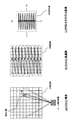
図6を参照して、本実施例におけるスキャン動作について説明する。 With reference to FIG. 6, the scanning operation in the present embodiment will be described.
同図(a)に示すように、ビーム照射装置の前方空間に設定された目標領域をマトリクス状に分割したとき、照射レーザ光は、スキャン軌跡上のマトリクスを順番に照射するようにしてスキャンされる。ここで、マトリクスのスキャン順序は任意に設定できる。同図(b)は、左上隅のマトリクス位置から順次1ラインずつスキャンするようにスキャン軌跡が設定されたときのものである。なお、スキャン軌道(スキャン順序)は、上述の如く、DSP制御回路10内のスキャンテーブルによって規定される。
As shown in FIG. 6A, when the target area set in the front space of the beam irradiation apparatus is divided into a matrix, the irradiation laser light is scanned so as to sequentially irradiate the matrix on the scan locus. The Here, the scan order of the matrix can be arbitrarily set. FIG. 5B shows the case where the scan trajectory is set so that one line is sequentially scanned from the matrix position in the upper left corner. Note that the scan trajectory (scan order) is defined by the scan table in the
同図(b)のようにしてスキャンされる場合、PSD600の受光面上における分離光の収束位置は、同図(c)に示す軌道に沿って移動する。ここで、同図(c)の軌道は、同図(b)のスキャン軌道に対し、一対一に対応している。したがって、同図(c)の軌道上における収束位置から照射レーザ光のスキャン位置を識別することができる。なお、この場合、同図(c)の軌道は、上述の如く、DSP制御回路10内の軌道テーブルに従うこととなる。
When scanning is performed as shown in FIG. 6B, the convergence position of the separated light on the light receiving surface of the
ビーム照射装置においては、同図(b)に示すスキャン軌道に沿って照射レーザ光がスキャンされるのが最も理想的である。しかし、通常は、ビーム照射装置に対して不所望な振動や外乱等が加えられることにより、照射レーザ光のスキャン位置が所期のスキャン軌道から外れてしまう。この場合、かかるスキャン位置の外れに応じて、有効受光面上における分離光の収束位置も同図(c)に示す軌道から外れることとなる。 In the beam irradiation apparatus, it is most ideal that the irradiation laser light is scanned along the scanning trajectory shown in FIG. However, normally, when an undesired vibration or disturbance is applied to the beam irradiation apparatus, the scanning position of the irradiation laser light deviates from the intended scan trajectory. In this case, in accordance with the deviation of the scan position, the convergence position of the separated light on the effective light receiving surface also deviates from the trajectory shown in FIG.
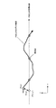
図7は、有効受光面上における分離光のスポット軌道の一例を示すものである。かかる場合、スキャン制御ルーチン10aは、上述の如く、分離光の収束位置を目標軌道に引き込むよう、アクチュエータ駆動回路40にサーボ信号を供給する。
FIG. 7 shows an example of the spot trajectory of the separated light on the effective light receiving surface. In this case, the scan control routine 10a supplies a servo signal to the
今、分離光の収束位置がP(x,y)にあり、このとき、目標軌道上にあるべき収束位置がP’(x',y')であるとする。ここで、目標軌道上の収束位置P’(x',y')は、DSP制御回路10内に設定された軌道テーブルから取得される。具体的には、照射レーザ光のスキャン位置に対応する収束位置が軌道テーブルから取得される。
Now, it is assumed that the convergence position of the separated light is P (x, y), and at this time, the convergence position that should be on the target trajectory is P ′ (x ′, y ′). Here, the convergence position P ′ (x ′, y ′) on the target trajectory is acquired from the trajectory table set in the
このとき、スキャン制御ルーチン10aは、P(x,y)とP’(x',y')をもとに、Ex=x−x’とEy=y−y’を演算し、演算結果をもとに、Ex=0、Ey=0になるよう、アクチュエータ駆動回路40にサーボ信号を供給する。これにより、照射レーザ光のスキャン位置は、当該タイミングにおいてスキャン軌道上にあるべきスキャン位置方向に引き戻される。これに応じて、分離光の収束位置も、当該タイミングにおいて目標軌道上にあるべき収束位置P’(x',y')の方向に引き込まれる。かかるサーボ動作によって、照射レーザ光は所期のスキャン軌道に追従するようスキャンされる。
At this time, the
このようにサーボを掛けながらスキャン動作を行っている間、スキャン制御ルーチン10aは、上述の如く、分離光の収束位置が、障害物検出や距離検出等を行うための位置(発光点)として予め設定され位置に到達したかを監視する。そして、収束位置が発光点に到達したタイミングにて、半導体レーザ100の出射パワーを一定期間だけパルス状に高レベルPwbに設定する。
While performing the scanning operation while applying the servo in this way, as described above, the scan control routine 10a preliminarily determines the separation light convergence position as a position (light emitting point) for performing obstacle detection, distance detection, and the like. Monitor whether the set position has been reached. Then, at the timing when the convergence position reaches the light emitting point, the emission power of the
ここで、収束位置が発光点に到達したかの判別は、収束位置と発光点の間の距離差が予め設定した距離差より小さくなったかによって行う。これにより、収束位置が目標軌道から多少外れていても、所期の収束位置近傍で、高パワーの発光を行うことができる。 Here, the determination of whether the convergence position has reached the light emitting point is made based on whether the distance difference between the convergence position and the light emitting point is smaller than a preset distance difference. Thereby, even if the convergence position is slightly deviated from the target trajectory, high-power light emission can be performed in the vicinity of the intended convergence position.
図8に、スキャン動作時のフローチャートを示す。 FIG. 8 shows a flowchart during the scanning operation.
S101にてスキャン動作が開始されると、S102にて半導体レーザ100から低パワー(Pwa)のレーザ光が出射された後、S103にて照射レーザ光の照射位置がホームポジションへ移動される。なお、ホームポジションは、たとえば、図6(b)に示すマトリクスのうち、左端で且つ上下方向中央あたりのマトリクス位置に設定される。さらに、S104にて照射レーザ光に対する軌道サーボがONとされた後、S105にてスキャン動作が開始される。
When the scanning operation is started in S101, a low-power (Pwa) laser beam is emitted from the
次に、S106にてスキャン位置が発光点に到達したかが判別される。発光点に到達していなければ、S108にてスキャン動作が終了したかが判別された後、S105に戻り、軌道サーボONの状態にて引き続きスキャン動作が実行される。他方、スキャン位置が発光点に到達した場合には、S107にて半導体レーザ100の出射レーザパワーが一定期間だけパルス状に高パワーPwbに設定され、高パワーの照射レーザ光が目標領域に照射される。このとき、目標領域からの反射光を受光することにより、当該ビーム照射装置を搭載した検出器において、障害物測定や距離測定等の処理が行われる。
Next, in S106, it is determined whether the scan position has reached the light emission point. If the light emission point has not been reached, it is determined in S108 whether or not the scanning operation has been completed, and then the processing returns to S105, and the scanning operation is continued in the state where the orbit servo is ON. On the other hand, when the scan position reaches the light emitting point, the output laser power of the
しかる後、S108にてスキャン動作が終了したかが判別され、終了していなければ、S105に戻り、上述のスキャン動作(低パワーPwaによる)が繰り返される。他方、スキャン動作が終了すれば、S109にて軌道サーボがOFFとされた後、S110にて半導体レーザがOFFとされる。 Thereafter, it is determined in S108 whether or not the scanning operation is completed. If not completed, the processing returns to S105 and the above-described scanning operation (by the low power Pwa) is repeated. On the other hand, when the scanning operation is completed, the trajectory servo is turned off in S109, and then the semiconductor laser is turned off in S110.
このように、本実施の形態によれば、照射レーザ光のスキャン位置が所期のスキャン軌道から外れた場合にも、これを当該スキャン軌道に円滑に引き戻すことができる。よって、不所望な振動や外乱がビーム照射装置に加えられた場合にも、安定したスキャン動作を実現することができる。 Thus, according to the present embodiment, even when the scan position of the irradiation laser beam deviates from the intended scan trajectory, it can be smoothly pulled back to the scan trajectory. Therefore, even when an undesired vibration or disturbance is applied to the beam irradiation apparatus, a stable scanning operation can be realized.
なお、上記では、図7を参照して説明したように、分離光の収束位置P(x,y)を、当該タイミングにおいて目標軌道上にあるべき収束位置P’(x',y')に引き込むようにしてサーボを掛けるようにしたが、この他のサーボ処理にて、分離光の収束位置を目標軌道上に引き込むようにすることもできる。たとえば、図9に示すように、当該タイミングよりΔTだけ経過したタイミングにおいて目標軌道上にあるべき収束位置P’(xa',ya')に引き込むようにすることもできる。この場合、DSP制御回路10は、P(x,y)とP’(xa',ya')をもとに、Ex=x−xa’とEy=y−ya’を演算し、演算結果をもとに、Ex=0、Ey=0になるよう、アクチュエータ駆動回路40にサーボ信号を供給する。こうすると、照射レーザ光のスキャン位置を次に予定されているスキャン位置に円滑に引き込むことができ、効率的なスキャン動作を実現することができる。
In the above description, as described with reference to FIG. 7, the convergence position P (x, y) of the separated light is changed to the convergence position P ′ (x ′, y ′) that should be on the target trajectory at the timing. Although the servo is applied so as to be pulled in, the convergence position of the separated light can be drawn onto the target trajectory by other servo processing. For example, as shown in FIG. 9, it may be drawn into the convergence position P ′ (xa ′, ya ′) that should be on the target trajectory at a timing after ΔT from the timing. In this case, the
次に、スキャンパターンとスキャン領域の設定について説明する。 Next, setting of a scan pattern and a scan area will be described.
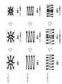
図10に、上記スキャン制御ルーチン10aにて設定され得るスキャンパターンのバリエーションを示す。なお、これらのスキャンパターンは、右左折時、高速走行時あるいは障害物検出時に用いて好ましいものである。これらのスキャンパターンは、上記の如く、レーザ光の照射位置を目標領域内においてスキャンさせるためのテーブル(スキャンテーブル)と、このテーブルに従ってレーザ光をスキャンさせたときの受光面上における分離光の収束位置の軌道を示すテーブル(軌道テーブル)として、DSP制御回路10に保持される。
FIG. 10 shows variations of scan patterns that can be set in the
図10(a)は、スキャン領域中心部のスキャン比重を高める場合のスキャンパターンである。このスキャンパターンは、高速走行時に用いて好ましいものである。すなわち、高速走行時には、自動車の走行路上、遠方に存在する障害物をいち早く検出する必要がある。図10(a)のように、スキャン領域中心部のスキャン比重を高めることにより、直進遠方位置のスキャン頻度が高められ、これにより、遠方位置にある障害物を円滑に検出することができる。 FIG. 10A shows a scan pattern for increasing the scan specific gravity at the center of the scan region. This scan pattern is preferable when used at high speeds. That is, when traveling at high speed, it is necessary to quickly detect an obstacle present in the distance on the road of the automobile. As shown in FIG. 10A, by increasing the scan specific gravity at the center of the scan region, the scan frequency of the rectilinear far position is increased, and thereby, an obstacle at the far position can be detected smoothly.
図10(b)は、左右幅方向中央部のスキャン比重を高める場合のスキャンパターンである。このスキャンパターンも図10(a)の場合と同様、高速走行時に用いて好ましいものである。すなわち、このスキャンパターンにおいても、直進遠方位置のスキャン頻度が高められるため、直進遠方位置にある障害物を円滑に検出することができる。 FIG. 10B shows a scan pattern for increasing the scan specific gravity at the center in the left-right width direction. This scan pattern is also preferable when used at high speeds, as in the case of FIG. That is, also in this scan pattern, since the scanning frequency of the farther forward position is increased, an obstacle at the farther straight position can be detected smoothly.
図10(c)は、上下幅方向中央部のスキャン比重を高める場合のスキャンパターンである。このスキャンパターンも、上記のパターンと同様、高速走行時に用いて好ましいものである。すなわち、このスキャンパターンにおいても、直進遠方位置のスキャン頻度が高められ、直進遠方位置にある障害物を円滑に検出することができる。また、このパターンの場合は、図10(b)の場合に比べ、スキャン頻度が大きい領域が左右方向に拡張されるため、障害物の検出精度を高め得る領域を直進左右方向に拡張することができる。よって、直進進行路に対する障害物の急な飛び出しの可能性等を検出することができる。 FIG. 10C shows a scan pattern for increasing the scan specific gravity at the center in the vertical width direction. This scan pattern is also preferable when used at high speeds, as in the above pattern. That is, also in this scan pattern, the scanning frequency of the farther forward position is increased, and an obstacle at the farther forward position can be detected smoothly. In the case of this pattern, as compared with the case of FIG. 10B, since the region having a high scanning frequency is expanded in the left-right direction, it is possible to extend the region that can improve the obstacle detection accuracy in the left-right direction. it can. Accordingly, it is possible to detect the possibility of a sudden jump out of an obstacle with respect to a straight traveling path.
図10(d)は、左右幅方向右側部分のスキャン比重を高める場合のスキャンパターンである。このスキャンパターンは、右折走行時に用いて好ましいものである。すなわち、右折走行時には、自動車が曲がろうとする右側部分に障害物が存在しないかをいち早く検出する必要がある。図10(d)のように、右側領域のスキャン比重を高めることにより、右側領域のスキャン頻度が高められ、これにより、進行方向右側位置にある障害物を円滑に検出することができる。なお、左右幅方向左側部分のスキャン比重を高める場合のスキャンパターンは、図10(d)のスキャンパターンを左右対称に折り返したものとなる。この場合は、左側領域のスキャン頻度が高められ、進行方向左側位置にある障害物を円滑に検出することができる。 FIG. 10D shows a scan pattern for increasing the scan specific gravity of the right portion in the left-right width direction. This scan pattern is preferable for use during right turn traveling. In other words, when turning right, it is necessary to quickly detect whether there is an obstacle on the right side where the car is about to turn. As shown in FIG. 10D, by increasing the scan specific gravity of the right region, the scan frequency of the right region is increased, and thereby an obstacle at the right position in the traveling direction can be detected smoothly. Note that the scan pattern in the case of increasing the scan specific gravity of the left portion in the left-right width direction is obtained by symmetrically folding the scan pattern of FIG. In this case, the frequency of scanning the left area is increased, and an obstacle at the left position in the traveling direction can be detected smoothly.
図10(e)は、左右幅方向右側部分のスキャン比重を高める場合のスキャンパターンである。このスキャンパターンも、上記図10(d)のパターンと同様、右折走行時に用いて好ましいものである。すなわち、このスキャンパターンにおいても、右側領域のスキャン頻度が高められるため、進行方向右側位置にある障害物を円滑に検出できる。なお、左右幅方向左側部分のスキャン比重を高める場合のスキャンパターンは、図10(e)のスキャンパターンを左右対称に折り返したものとなる。この場合は、左側領域のスキャン頻度が高められ、進行方向左側位置にある障害物を円滑に検出することができる。 FIG. 10E shows a scan pattern for increasing the scan specific gravity of the right portion in the left-right width direction. This scan pattern is also preferable for right turn traveling, as in the pattern of FIG. That is, also in this scan pattern, since the scan frequency of the right region is increased, the obstacle at the right position in the traveling direction can be detected smoothly. Note that the scan pattern in the case of increasing the scan specific gravity of the left portion in the left-right width direction is obtained by symmetrically folding the scan pattern of FIG. In this case, the frequency of scanning the left area is increased, and an obstacle at the left position in the traveling direction can be detected smoothly.
図10(f)は、スキャン領域内のある一点(目標位置)のスキャン比重を高める場合のスキャンパターンである。このスキャンパターンは、障害物検出時に用いて好ましいものである。すなわち、障害物検出位置を目標位置に設定することにより、障害物位置近傍のスキャン頻度が高められ、障害物の位置変化等を円滑に検出できる。なお、図10(f)のスキャンパターンは、図10(a)のスキャンパターンのスキャン原点(図10(a)ではスキャン領域中心部)を目標位置に変更する演算処理を実行することにより取得することができる。この場合、DSP制御回路10には、図10(a)のスキャンパターンが保持される。スキャン制御ルーチン10aは、保持されたスキャンパターンに対して、スキャン原点を変更するための演算処理を実行する。
FIG. 10F shows a scan pattern for increasing the scan specific gravity at a certain point (target position) in the scan area. This scan pattern is preferable for use when detecting an obstacle. That is, by setting the obstacle detection position as the target position, the scan frequency near the obstacle position can be increased, and a change in the position of the obstacle can be detected smoothly. Note that the scan pattern in FIG. 10F is acquired by executing a calculation process for changing the scan origin of the scan pattern in FIG. 10A (the center of the scan area in FIG. 10A) to the target position. be able to. In this case, the
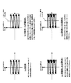
図11および図12は、右折走行時におけるスキャン領域とスキャンパターンの変更例を示すものである。 FIG. 11 and FIG. 12 show examples of changing the scan area and the scan pattern during right turn traveling.
まず、図11を参照して、直進走行時には、同図(a)のスキャンパターンが設定されている。この状態から、ドライバーがハンドルを右側に旋回し右折操舵に関する信号がスキャン制御ルーチン10aに入力されると、同図(b)(c)(d)に示す如く、スキャン領域のシフトあるいはスキャンパターンの変更が行われる。
First, referring to FIG. 11, when traveling straight ahead, the scan pattern shown in FIG. 11A is set. From this state, when the driver turns the steering wheel to the right and a signal related to right turn steering is input to the
図11(b)は、進行方向前方の中心軸に対してスキャン領域が右側にそのままシフトされるときの例を示している。この場合、進行方向前方の中心軸に対して非対称な範囲(右側にシフトした範囲)がスキャンされる。これにより、自動車が曲がろうとする右側部分に障害物が存在しないかをいち早く検出することができる。この場合、DSP制御回路10には図11(a)のスキャンパターンが保持される。また、スキャン制御ルーチン10aは、保持されたスキャンパターンに対して、スキャン領域を操舵方向およびその角度に応じて変更するための処理を実行する。なお、この場合、スキャン領域の中心軸と進行方向の中心軸との角度は、たとえば、操舵角度に対して単純増加となるように設定される。 図11(c)は、スキャン領域はシフトせずに、スキャンパターンを右側領域の比重が高められるパターンに変更するときの例を示している。この場合も、右折方向に障害物が存在しないかをいち早く検出することができる。また、進行方向前方の中心軸に対して対称な領域がスキャンされるため、図11(a)の場合と異なり、進行方向前方方向の障害物も検出できる。なお、この場合、DSP制御回路10には、図11(a)のスキャンパターンの他に、図11(c)のスキャンパターンが保持される。また、スキャン制御ルーチン10aは、保持されたスキャンパターンのうち操舵方向に対応するスキャンパターンを選択設定する処理を実行する。
FIG. 11B shows an example when the scan area is shifted to the right as it is with respect to the central axis in front of the traveling direction. In this case, an asymmetrical range (a range shifted to the right side) with respect to the central axis ahead of the traveling direction is scanned. As a result, it is possible to quickly detect whether there is an obstacle in the right side portion where the automobile is about to turn. In this case, the
図11(d)は、スキャン領域を右側にシフトさせ、さらに、スキャンパターンを右側領域の比重が高められるパターンに変更するときの例を示している。この場合は、図11(b)および図11(c)の場合よりもさらに右折方向に障害物が存在しないかをいち早く検出することができる。なお、この場合、DSP制御回路10には、図11(a)のスキャンパターンの他に、図11(c)のスキャンパターンが保持される。また、スキャン制御ルーチン10aは、保持されたスキャンパターンのうち、舵方向に対応するスキャンパターンを選択設定する処理と、操舵方向およびその角度に応じてスキャン領域を変更するための処理を実行する。
FIG. 11D shows an example in which the scan area is shifted to the right, and the scan pattern is changed to a pattern in which the specific gravity of the right area is increased. In this case, it is possible to quickly detect whether there is an obstacle in the right turn direction as compared with the cases of FIGS. 11B and 11C. In this case, the
図12は、図11の例において、直進走行時のスキャンパターンを、図11(a)のスキャンパターンから図12(a)のスキャンパターンに置き換えた場合を例示するものである。この場合、右折操舵に関する信号がスキャン制御ルーチン10aに入力されると、同図(b)(c)(d)に示す如く、スキャン領域のシフトあるいはスキャンパターンの変更が行われる。これらの例においては、図11(a)(b)(c)の例と同様、右側部分に障害物が存在しないかをいち早く検出することができる。
FIG. 12 illustrates a case where the scan pattern during straight traveling is replaced with the scan pattern of FIG. 12A from the scan pattern of FIG. 11A in the example of FIG. In this case, when a signal related to right turn steering is input to the
なお、左折操舵時の場合には、図11および図12の例とは反対に、スキャン領域が左側にシフトされ、あるいは、スキャンパターンが左側領域加重のパターンに変更される。 In the case of left turn steering, the scan area is shifted to the left side, or the scan pattern is changed to the left area weight pattern, contrary to the examples of FIGS.
図13は、走行速度が増加したときのスキャン領域とスキャンパターンの変更例を示すものである。図中、速度1は第1の閾値速度を越えるまでの走行速度、速度2は第1の閾値速度を越えてから第2の閾値速度を越えるまでの走行速度、速度3は第2の閾値速度を越える速度である。この場合、スキャン制御ルーチン10aは、外部信号として走行速度に関する信号をモニタし、そのときの速度に応じて、スキャン領域とスキャンパターンを適宜変更する。
FIG. 13 shows an example of changing the scan area and scan pattern when the traveling speed increases. In the figure,
図13(a)(b)の例では、速度の増加に応じてスキャン領域が次第に縮小される。これにより、直進遠方位置のスキャン頻度が高められ、直進遠方位置にある障害物を円滑に検出できるようになる。なお、この場合、DSP制御回路10には、速度1のときに適用されるスキャンパターンが保持される。また、スキャン制御ルーチン10aは、スキャン領域を走行速度に応じて変更するための処理を実行する。
In the examples of FIGS. 13A and 13B, the scan area is gradually reduced as the speed increases. As a result, the frequency of scanning in the straight far position is increased, and an obstacle in the straight far position can be detected smoothly. In this case, the
図13(c)の例では、まず、速度の増加に応じてスキャンパターンが中央部加重のパターンに変更され、さらに速度が増加するとスキャン領域が縮小される。この例においても、直進遠方位置のスキャン頻度が高められ、直進遠方位置にある障害物を円滑に検出できる。なお、この場合、DSP制御回路10には、速度1のときに適用されるスキャンパターンと速度1のときに適用されるスキャンパターンが保持される。また、スキャン制御ルーチン10aは、そのときの速度に応じてスキャンパターンを選択設定する処理と、スキャン領域を走行速度に応じて変更するための処理を実行する。
In the example of FIG. 13C, first, the scan pattern is changed to a center weighted pattern as the speed increases, and the scan area is reduced as the speed further increases. Also in this example, the scanning frequency of the straight far position is increased, and an obstacle at the straight far position can be detected smoothly. In this case, the
図14は、障害物検出時におけるスキャンパターンの変化を示すものである。 FIG. 14 shows a change in scan pattern when an obstacle is detected.
同図(a)に示す通常走行時において、同図(b)または(c)に示す如く、スキャン領域内に障害物が検出されると、スキャンパターンの原点位置が障害物検出位置に変更され、それに応じてスキャン領域のスキャン軌跡が同図に示すように変更される。このスキャン軌跡の変更により、障害物位置近傍のスキャン頻度が高められ、障害物の位置変化等を円滑に検出できる。この場合、DSP制御回路10には、図14(a)のスキャンパターンが保持される。また、スキャン制御ルーチン10aは、保持されたスキャンパターンに対して、スキャン原点を障害物検出位置に変更してスキャン軌跡を再設定するための演算処理を実行する。
During normal travel shown in FIG. 6A, when an obstacle is detected in the scan area, the origin position of the scan pattern is changed to the obstacle detection position as shown in FIG. Accordingly, the scan trajectory of the scan area is changed as shown in FIG. By changing the scan trajectory, the frequency of scanning near the obstacle position is increased, and a change in the position of the obstacle can be detected smoothly. In this case, the
図15は、操舵方向と速度が変化したことに応じてスキャンパターンを変更する場合の処理フローチャートである。 FIG. 15 is a process flowchart in the case where the scan pattern is changed in accordance with changes in the steering direction and speed.
スキャン動作が開始されると、まず、スキャンパターンの原点位置がスキャン領域の中心位置に設定される。(S11)さらに、通常走行時に適用されるべきスキャンパターンがスキャン動作時のパターンとして設定される(S12)。次に、逐次入力される外部信号をもとに、進行方向に変化があるか(右旋回操舵or左旋回操舵)が判別され(S13)、進行方向に変化があれば(S13:Yes)、初期設定されたスキャンパターンが、変化方向のスキャン比重を高めるスキャンパターン(たとえば、図11b〜dまたは図12b〜d)に変更される(S14)。進行方向に変化がなければ(S13:No)、初期設定されたスキャンパターンのままとされる。 When the scan operation is started, first, the origin position of the scan pattern is set to the center position of the scan area. (S11) Further, a scan pattern to be applied during normal running is set as a pattern during a scan operation (S12). Next, it is determined whether there is a change in the traveling direction (right turn steering or left turn steering) based on the external signal that is sequentially input (S13), and if there is a change in the travel direction (S13: Yes). The initially set scan pattern is changed to a scan pattern that increases the scan specific gravity in the changing direction (for example, FIG. 11b to d or FIG. 12b to d) (S14). If there is no change in the direction of travel (S13: No), the scan pattern that has been initially set is maintained.
このようにしてスキャンパターンの設定がなされると、次に、そのとき入力される走行速度に関する外部信号をもとに走行速度が所定の閾値を越えているかが判別される(S15)。ここで、走行速度が閾値を越えていれば(S15:Yes)、走行速度に応じてスキャン領域が通常のスキャン領域よりも縮小され、走行方向中央部分のスキャン比重が高められる(S16)。走行速度が閾値を越えていなければ(S15:No)、通常のスキャン領域が当該スキャン動作時のスキャン領域として設定される。 Once the scan pattern is set in this way, it is next determined whether or not the traveling speed exceeds a predetermined threshold based on the external signal relating to the traveling speed inputted at that time (S15). Here, if the traveling speed exceeds the threshold value (S15: Yes), the scan area is reduced as compared with the normal scan area in accordance with the traveling speed, and the scan specific gravity at the central portion in the traveling direction is increased (S16). If the traveling speed does not exceed the threshold (S15: No), the normal scan area is set as the scan area during the scan operation.
しかして、スキャンパターンとスキャン領域が設定されると、そのスキャン領域にスキャンパターンを当てはめて当該スキャン動作時のスキャン軌跡が設定される。そして、このスキャン軌跡に沿ってレーザ光がスキャンされ、そのときの反射光の状態から、各スキャン位置における障害物の検出と障害物までの距離測定処理が行われる(S17)。 Thus, when the scan pattern and the scan area are set, the scan locus is set by applying the scan pattern to the scan area. Then, the laser beam is scanned along this scan locus, and the obstacle detection and the distance measurement process at each scan position are performed from the state of the reflected light at that time (S17).
このようにして、1回のスキャン動作が終了すると、S11に戻り、同様の処理が繰り返し行われる。そして、スキャン毎に障害物の検出と障害物までの距離測定処理が行われ、自動車の走行状態を制御する制御回路等に出力される。 In this way, when one scan operation is completed, the process returns to S11 and the same processing is repeated. Then, for each scan, an obstacle is detected and a distance to the obstacle is measured and output to a control circuit or the like that controls the running state of the automobile.
なお、S16では、スキャン領域を縮小するに代えて、別のスキャンパターンを設定するようにしても良い。たとえば、S13にて進行方向に変化がないとされた場合は、S12にて初期化されたスキャンパターンを、S16にて高速走行時に適したスキャンパターンに変更するようにしても良い。具体的には、初期設定されたスキャンパターンが図12(a)に示すものである場合、これをS16にて図10(a)または(b)のものに変更するようにしても良い。あるいは、S13にて設定された右左折時に適したスキャンパターン、たとえば、図11(c)または図12(c)のスキャンパターンを、高速走行時と右左折時の両方に適したスキャンパターン、たとえば、スキャン領域のうち進行方向中央部と操舵方向側部のスキャン頻度を高めたスキャンパターンに変更するようにしてもよい。 In S16, instead of reducing the scan area, another scan pattern may be set. For example, if it is determined in S13 that there is no change in the traveling direction, the scan pattern initialized in S12 may be changed to a scan pattern suitable for high-speed traveling in S16. More specifically, when the initially set scan pattern is as shown in FIG. 12A, it may be changed to that of FIG. 10A or 10B at S16. Alternatively, a scan pattern suitable at the time of turning left and right set in S13, for example, the scan pattern of FIG. 11C or FIG. 12C, a scan pattern suitable for both high-speed driving and right-left turn, for example, The scan pattern may be changed to a scan pattern in which the scan frequency of the central portion in the traveling direction and the side portion in the steering direction is increased.
また、S14では、スキャンパターンの変更に代えて、あるいは、スキャンパターンの変更とともに、たとえば図11(b)(d)および図12(b)(d)に示すように、スキャン領域を操舵方向にシフトさせるようにしても良い。 In S14, instead of changing the scan pattern, or together with changing the scan pattern, as shown in FIGS. 11B, 12D, 12B, and 12D, for example, the scan area is set in the steering direction. You may make it shift.
なお、図15は、操舵方向と速度が変化したことに応じてスキャンパターンを変更する場合の処理フローチャートであるが、操舵方向の変化のみに応じてスキャンパターンを変更する場合には、図15のS15、16が省略される。また、速度の変化のみに応じてスキャンパターンを変更する場合には、図15のS13、14が省略される。 FIG. 15 is a process flowchart in the case where the scan pattern is changed in accordance with changes in the steering direction and speed. However, in the case where the scan pattern is changed only in accordance with the change in the steering direction, FIG. S15 and 16 are omitted. Further, when the scan pattern is changed only in accordance with the change in speed, S13 and S14 in FIG. 15 are omitted.
図15のフローチャートによれば、右左折時に操舵方向に存在する障害物をいち早く検出できるとともに、高速走行時に走行方向遠方に存在する障害物をいち早く検出することができる。 According to the flowchart of FIG. 15, obstacles existing in the steering direction when turning right or left can be detected quickly, and obstacles existing far away in the traveling direction can be detected quickly when traveling at high speed.
図16は、障害物を検出したことに応じてスキャンパターンを変更する場合の処理フローチャートである。 FIG. 16 is a process flowchart in the case where the scan pattern is changed in response to detection of an obstacle.
スキャン動作が開始されると、まず、スキャンパターンの原点位置がスキャン領域の中心位置に設定され(S21)、さらに、通常走行時に適用されるべきスキャンパターンがスキャン動作時のパターンとして設定される(S22)。次に、設定されたスキャン領域にスキャンパターンを当てはめてスキャン動作時のスキャン軌跡が設定される。そして、このスキャン軌跡に沿ってレーザ光がスキャンされ、そのときの反射光の状態から、各スキャン位置における障害物の検出と障害物までの距離測定が行われる(S23)。 When the scan operation is started, first, the origin position of the scan pattern is set to the center position of the scan region (S21), and further, the scan pattern to be applied during normal running is set as the pattern during the scan operation ( S22). Next, a scan locus at the time of the scan operation is set by applying a scan pattern to the set scan area. Then, the laser beam is scanned along the scanning locus, and the obstacle is detected at each scanning position and the distance to the obstacle is measured from the state of the reflected light at that time (S23).
かかる処理においてスキャン領域内に障害物が検出されると、各スキャン位置における障害物までの距離をもとに最も近いスキャン位置(スキャン領域内の座標位置)が決定される(S24)。そして、この最も近いスキャン位置における障害物までの距離が閾値距離よりも小さいかが判別され(S25)、小さければ(S25:Yes)、この位置をスキャン座標の原点位置に設定して、設定後の原点位置に応じたスキャン軌跡が演算により求められる(S26)。次のスキャンタイミングでは、求めたスキャン軌跡に沿ってレーザ光がスキャンされる。そして、各スキャン位置における障害物の検出と障害物までの距離の測定処理が行われる(S23)。 When an obstacle is detected in the scan area in this process, the closest scan position (coordinate position in the scan area) is determined based on the distance to the obstacle at each scan position (S24). Then, it is determined whether or not the distance to the obstacle at the nearest scan position is smaller than the threshold distance (S25). If it is smaller (S25: Yes), this position is set as the origin position of the scan coordinates, and after setting A scan locus corresponding to the origin position is obtained by calculation (S26). At the next scan timing, the laser beam is scanned along the obtained scan locus. Then, an obstacle is detected at each scan position and a distance measurement process is performed (S23).
かかるスキャン軌跡の再設定とそれによるスキャン動作は、スキャン領域内において障害物が検出されなくなるか、あるいは、最も近いスキャン位置における障害物までの距離が閾値距離よりも大きくなるまで繰り返される(S25:Yes→S26)。S25における判別がNoとなると、S21に戻り、スキャン原点位置とスキャンパターンが初期設定され(S21、S22)、これをもとにした障害物検出と距離測定が行われる(S23)。 The resetting of the scan trajectory and the scanning operation thereby are repeated until no obstacle is detected in the scan area or the distance to the obstacle at the nearest scan position is larger than the threshold distance (S25: Yes → S26). If the determination in S25 is No, the process returns to S21, the scan origin position and scan pattern are initialized (S21, S22), and obstacle detection and distance measurement based on this are performed (S23).
図16のフローチャートによれば、障害物の検出に応じて障害物位置近傍のスキャン頻度が高められるため、障害物の位置変化等を円滑に検出できる。 According to the flowchart of FIG. 16, since the scan frequency near the obstacle position is increased according to the detection of the obstacle, a change in the position of the obstacle can be detected smoothly.
以上、本発明に係る実施の形態について説明したが、本発明は上記実施の形態に限定されるものではない。 As mentioned above, although embodiment which concerns on this invention was described, this invention is not limited to the said embodiment.
たとえば、上記実施の形態は、自動車用のビーム照射装置に本発明を適用したものであったが、船舶や飛行機等、他の移動体用のビーム照射装置に本発明を適用することも可能である。 For example, in the above-described embodiment, the present invention is applied to a beam irradiation apparatus for automobiles. However, the present invention can also be applied to a beam irradiation apparatus for other moving bodies such as ships and airplanes. is there.
本発明の実施の形態は、特許請求の範囲に示された技術的思想の範囲内において、適宜、種々の変更が可能である。 The embodiments of the present invention can be appropriately modified in various ways within the scope of the technical idea shown in the claims.
10 DSP制御回路
30 レーザ駆動回路
40 アクチュエータ駆動回路
50 ビーム照射ヘッド
60 PSD信号処理回路
80 PD信号処理回路
100 半導体レーザ
300 レンズアクチュエータ
301 照射レンズ
400 ビームスプリッタ
500 集光レンズ
600 PSD
700 受光レンズ
800 光検出器
DESCRIPTION OF
700 Light-receiving
Claims (12)
前記レーザ光のスキャン軌跡を該検出装置が搭載される移動体の移動状態に関する信号に基づいて制御するスキャン制御手段を有する、
ことを特徴とする検出装置。 In a detection device that irradiates a target area with laser light and detects an obstacle in the target area,
Scan control means for controlling a scan trajectory of the laser light based on a signal relating to a moving state of a moving body on which the detection device is mounted;
A detection device characterized by that.
前記スキャン制御手段は、前記移動体の進行方向および/もしくは進行速度に関する信号に基づいて、前記レーザ光のスキャン軌跡を設定する、
ことを特徴とする検出装置。 In claim 1,
The scan control means sets a scan locus of the laser beam based on a signal related to the traveling direction and / or traveling speed of the moving body.
A detection device characterized by that.
前記スキャン制御手段は、前記移動体の進行方向に関する信号に基づいて、前記レーザ光のスキャン軌跡を、前記進行方向の中心軸から前記進行方向の変化方向に偏った部分のスキャン頻度が高められるスキャン軌跡に設定する、
ことを特徴とする検出装置。 In claim 2,
The scan control means is configured to increase the scan frequency of a portion where the scan locus of the laser beam is deviated from the central axis of the traveling direction toward the changing direction of the traveling direction based on a signal related to the traveling direction of the moving body. Set to the trajectory,
A detection device characterized by that.
前記スキャン制御手段は、前記移動体の進行方向に関する信号に基づいて、前記目標領域を、前記進行方向の中心軸から前記進行方向の変化方向にシフトさせる、
ことを特徴とする検出装置。 In claim 3,
The scan control means shifts the target area from a central axis of the traveling direction to a direction of change of the traveling direction based on a signal related to the traveling direction of the moving body.
A detection device characterized by that.
前記スキャン制御手段は、前記移動体の進行方向に関する信号に基づいて、前記目標領域内における前記レーザ光のスキャンパターンを、前記目標領域の中心部から前記進行方向の変化方向に偏った部分のスキャン頻度が高められるスキャンパターンに設定する、
ことを特徴とする検出装置。 In claim 3 or 4,
The scan control unit scans a portion of the scan pattern of the laser beam in the target area that is biased from the center of the target area in the direction of change of the travel direction based on a signal related to the direction of travel of the moving body. Set the scan pattern to a higher frequency,
A detection device characterized by that.
前記スキャン制御手段は、前記移動体の進行速度に関する信号に基づいて、前記レーザ光のスキャン軌跡を、前記進行方向の中心部分のスキャン頻度が高められるスキャン軌跡に設定する、
ことを特徴とする検出装置。 In claim 2,
The scan control means sets the scan trajectory of the laser light to a scan trajectory that increases the scan frequency of the central portion in the traveling direction, based on a signal related to the traveling speed of the moving body.
A detection device characterized by that.
前記スキャン制御手段は、前記移動体の進行速度に関する信号に基づいて、前記目標領域を、前記進行方向の中心部分に向けて縮小させる、
ことを特徴とする検出装置。 In claim 6,
The scan control unit reduces the target area toward a central portion in the traveling direction based on a signal related to the traveling speed of the moving body.
A detection device characterized by that.
前記スキャン制御手段は、前記移動体の進行速度に関する信号に基づいて、前記目標領域内における前記レーザ光のスキャンパターンを、前記目標領域の中心部分のスキャン頻度が高められるスキャンパターンに設定する、
ことを特徴とする検出装置。 In claim 6 or 7,
The scan control means sets the scan pattern of the laser light in the target area to a scan pattern that can increase the scan frequency of the central portion of the target area, based on a signal related to the traveling speed of the moving body.
A detection device characterized by that.
前記レーザ光のスキャン軌跡を前記障害物の検出結果に基づいて制御するスキャン制御手段を有する、
ことを特徴とする検出装置。 In a detection device that irradiates a target area with laser light and detects an obstacle in the target area,
Scan control means for controlling a scan trajectory of the laser light based on a detection result of the obstacle;
A detection device characterized by that.
前記スキャン制御手段は、前記障害物の検出結果に基づいて、前記レーザ光のスキャン軌跡を、前記障害物近傍のスキャン頻度が高められるスキャン軌跡に設定する、
ことを特徴とする検出装置。 In claim 9,
The scan control means sets the scan trajectory of the laser light to a scan trajectory that increases the scan frequency near the obstacle based on the obstacle detection result.
A detection device characterized by that.
前記スキャン制御手段は、前記障害物の検出結果に基づいて、前記スキャン軌跡の原点を前記障害物の検出位置に設定し、前記目標領域内における前記レーザ光のスキャンパターンを、前記設定された原点に反復回帰するスキャンパターンに設定する、
ことを特徴とする検出装置。 In claim 10,
The scan control means sets the origin of the scan locus to the obstacle detection position based on the obstacle detection result, and sets the scan pattern of the laser light in the target area to the set origin. Set the scan pattern to recursively return to
A detection device characterized by that.
前記スキャン制御手段は、前記障害物との距離が閾値距離よりも小さいときに、前記レーザ光のスキャン軌跡を前記障害物近傍のスキャン頻度が高められるスキャン軌跡に設定する、
ことを特徴とする検出装置。 In any of claims 9 to 11,
The scan control means sets the scan trajectory of the laser light to a scan trajectory that increases the scan frequency near the obstacle when the distance to the obstacle is smaller than a threshold distance.
A detection device characterized by that.
Priority Applications (3)
| Application Number | Priority Date | Filing Date | Title |
|---|---|---|---|
| JP2005076357A JP2006258604A (en) | 2005-03-17 | 2005-03-17 | Detection device |
| CNA2006100717128A CN1834686A (en) | 2005-03-17 | 2006-03-16 | Detection device |
| US11/377,449 US7570346B2 (en) | 2005-03-17 | 2006-03-17 | Detection device |
Applications Claiming Priority (1)
| Application Number | Priority Date | Filing Date | Title |
|---|---|---|---|
| JP2005076357A JP2006258604A (en) | 2005-03-17 | 2005-03-17 | Detection device |
Publications (1)
| Publication Number | Publication Date |
|---|---|
| JP2006258604A true JP2006258604A (en) | 2006-09-28 |
Family
ID=37002507
Family Applications (1)
| Application Number | Title | Priority Date | Filing Date |
|---|---|---|---|
| JP2005076357A Pending JP2006258604A (en) | 2005-03-17 | 2005-03-17 | Detection device |
Country Status (3)
| Country | Link |
|---|---|
| US (1) | US7570346B2 (en) |
| JP (1) | JP2006258604A (en) |
| CN (1) | CN1834686A (en) |
Cited By (23)
| Publication number | Priority date | Publication date | Assignee | Title |
|---|---|---|---|---|
| JP2006284196A (en) * | 2005-03-31 | 2006-10-19 | Sanyo Electric Co Ltd | Beam irradiation apparatus |
| JP2006329971A (en) * | 2005-04-27 | 2006-12-07 | Sanyo Electric Co Ltd | Detector |
| JP2008191099A (en) * | 2007-02-07 | 2008-08-21 | Olympus Imaging Corp | Light projection device |
| JP2008191098A (en) * | 2007-02-07 | 2008-08-21 | Olympus Imaging Corp | Light projection device |
| JP2009300399A (en) * | 2008-06-17 | 2009-12-24 | Olympus Imaging Corp | Light irradiation device |
| JP2013015338A (en) * | 2011-06-30 | 2013-01-24 | Fujitsu Ltd | Monitoring device and monitoring method |
| JP2013156139A (en) * | 2012-01-30 | 2013-08-15 | Ihi Corp | Moving object detecting apparatus and moving object detecting method |
| JP2013156138A (en) * | 2012-01-30 | 2013-08-15 | Ihi Corp | Moving object detecting apparatus |
| JP2014119414A (en) * | 2012-12-19 | 2014-06-30 | Fujitsu Ltd | Distance measuring device, distance measuring method, and program |
| JP2016029373A (en) * | 2015-08-21 | 2016-03-03 | 国立研究開発法人宇宙航空研究開発機構 | Multi-lidar system |
| JP2017505907A (en) * | 2014-01-29 | 2017-02-23 | エルジー イノテック カンパニー リミテッド | Depth information extraction apparatus and method |
| WO2018038262A1 (en) | 2016-08-26 | 2018-03-01 | パイオニア株式会社 | Measurement device, measurement method and program |
| WO2018043540A1 (en) | 2016-08-31 | 2018-03-08 | パイオニア株式会社 | Control device, measuring device, control method, and program |
| WO2019098263A1 (en) * | 2017-11-16 | 2019-05-23 | 日本電気株式会社 | Distance measurement apparatus, distance measurement method and program |
| JP2019090628A (en) * | 2017-11-10 | 2019-06-13 | パイオニア株式会社 | Scanning device |
| JP2019095352A (en) * | 2017-11-24 | 2019-06-20 | パイオニア株式会社 | Ranging device |
| WO2020049892A1 (en) * | 2018-09-03 | 2020-03-12 | 日立オートモティブシステムズ株式会社 | Vehicle-mounted radar system |
| JP2020509389A (en) * | 2017-03-08 | 2020-03-26 | ブリックフェルト ゲゼルシャフト ミット ベシュレンクテル ハフツング | LIDAR system with flexible scan parameters |
| JP2021021691A (en) * | 2019-07-30 | 2021-02-18 | 日本信号株式会社 | Distance measuring device |
| WO2021070570A1 (en) * | 2019-10-11 | 2021-04-15 | 株式会社デンソー | Optical distance-measuring device and control method for optical distance-measuring device |
| CN113281781A (en) * | 2020-01-31 | 2021-08-20 | 株式会社电装 | Optical detector |
| JP2021530716A (en) * | 2018-06-27 | 2021-11-11 | ベロダイン ライダー ユーエスエー,インコーポレイテッド | Laser radar |
| JP2022022400A (en) * | 2017-11-10 | 2022-02-03 | パイオニア株式会社 | Scanner |
Families Citing this family (9)
| Publication number | Priority date | Publication date | Assignee | Title |
|---|---|---|---|---|
| US7978313B2 (en) * | 2008-05-30 | 2011-07-12 | The Boeing Company | Systems and methods for targeting directed energy devices |
| KR101632873B1 (en) | 2014-09-05 | 2016-07-01 | 현대모비스 주식회사 | System and method for detecting obstacles |
| CN104656101B (en) * | 2015-01-30 | 2015-11-18 | 福州华鹰重工机械有限公司 | A kind of obstacle detection method |
| KR102547651B1 (en) * | 2016-09-20 | 2023-06-26 | 이노비즈 테크놀로지스 엘티디 | Lidar systems and methods |
| US10942272B2 (en) * | 2016-12-13 | 2021-03-09 | Waymo Llc | Power modulation for a rotary light detection and ranging (LIDAR) device |
| CN107356937A (en) * | 2017-08-25 | 2017-11-17 | 长春德信光电技术有限公司 | A kind of walking robot collision warning device based on Laser Detection Technique |
| US11378956B2 (en) * | 2018-04-03 | 2022-07-05 | Baidu Usa Llc | Perception and planning collaboration framework for autonomous driving |
| CN111762093A (en) * | 2019-03-14 | 2020-10-13 | 华芯半导体研究中心(广州)有限公司 | Vehicle lamp assembly, vehicle and control method of vehicle |
| US11740333B2 (en) | 2019-12-04 | 2023-08-29 | Waymo Llc | Pulse energy plan for light detection and ranging (lidar) devices based on areas of interest and thermal budgets |
Citations (10)
| Publication number | Priority date | Publication date | Assignee | Title |
|---|---|---|---|---|
| JPS56137262A (en) * | 1980-03-31 | 1981-10-27 | Tech Res & Dev Inst Of Japan Def Agency | Infrared ray tracker |
| JPS6222089A (en) * | 1985-07-23 | 1987-01-30 | Mitsubishi Electric Corp | Target detecting device |
| JPH05203740A (en) * | 1992-01-29 | 1993-08-10 | Mazda Motor Corp | Obstacle detector for vehicle |
| JPH08152476A (en) * | 1994-11-30 | 1996-06-11 | Nec Eng Ltd | Obstacle detection apparatus |
| JPH10147197A (en) * | 1996-11-19 | 1998-06-02 | Unisia Jecs Corp | Obstruction detecting device |
| JPH11153664A (en) * | 1997-09-30 | 1999-06-08 | Sumitomo Electric Ind Ltd | Object detector utilizing repetitively pulsed light |
| JPH11160436A (en) * | 1997-11-28 | 1999-06-18 | Unisia Jecs Corp | Obstacle detecting device |
| JP2001050723A (en) * | 1999-08-11 | 2001-02-23 | Minolta Co Ltd | Distance measuring equipment |
| JP2004347574A (en) * | 2003-05-26 | 2004-12-09 | Nissan Motor Co Ltd | Preceding vehicle detection device |
| JP2006153820A (en) * | 2004-12-01 | 2006-06-15 | Sanyo Electric Co Ltd | Beam radiation unit |
Family Cites Families (7)
| Publication number | Priority date | Publication date | Assignee | Title |
|---|---|---|---|---|
| JPS59203975A (en) * | 1983-05-06 | 1984-11-19 | Nissan Motor Co Ltd | Light radar device for vehicle |
| US5153722A (en) * | 1991-01-14 | 1992-10-06 | Donmar Ltd. | Fire detection system |
| DE19833065B4 (en) * | 1997-07-22 | 2010-04-15 | DENSO CORPORATION, Kariya-shi | An angular displacement determining device for determining the angular displacement of the radar center axis for use in a self-locating obstacle detection system |
| JP4054106B2 (en) | 1998-05-12 | 2008-02-27 | オリンパス株式会社 | Distance measuring device |
| DE10127204A1 (en) * | 2001-06-05 | 2003-03-20 | Ibeo Automobile Sensor Gmbh | Registration procedure and device |
| JP2003149338A (en) * | 2001-11-09 | 2003-05-21 | Denso Corp | Object recognition device and distance measuring device |
| US7042387B2 (en) * | 2004-02-06 | 2006-05-09 | Aviation Communication & Surveillance Systems Llc | Systems and methods for displaying hazards |
-
2005
- 2005-03-17 JP JP2005076357A patent/JP2006258604A/en active Pending
-
2006
- 2006-03-16 CN CNA2006100717128A patent/CN1834686A/en active Pending
- 2006-03-17 US US11/377,449 patent/US7570346B2/en not_active Expired - Fee Related
Patent Citations (10)
| Publication number | Priority date | Publication date | Assignee | Title |
|---|---|---|---|---|
| JPS56137262A (en) * | 1980-03-31 | 1981-10-27 | Tech Res & Dev Inst Of Japan Def Agency | Infrared ray tracker |
| JPS6222089A (en) * | 1985-07-23 | 1987-01-30 | Mitsubishi Electric Corp | Target detecting device |
| JPH05203740A (en) * | 1992-01-29 | 1993-08-10 | Mazda Motor Corp | Obstacle detector for vehicle |
| JPH08152476A (en) * | 1994-11-30 | 1996-06-11 | Nec Eng Ltd | Obstacle detection apparatus |
| JPH10147197A (en) * | 1996-11-19 | 1998-06-02 | Unisia Jecs Corp | Obstruction detecting device |
| JPH11153664A (en) * | 1997-09-30 | 1999-06-08 | Sumitomo Electric Ind Ltd | Object detector utilizing repetitively pulsed light |
| JPH11160436A (en) * | 1997-11-28 | 1999-06-18 | Unisia Jecs Corp | Obstacle detecting device |
| JP2001050723A (en) * | 1999-08-11 | 2001-02-23 | Minolta Co Ltd | Distance measuring equipment |
| JP2004347574A (en) * | 2003-05-26 | 2004-12-09 | Nissan Motor Co Ltd | Preceding vehicle detection device |
| JP2006153820A (en) * | 2004-12-01 | 2006-06-15 | Sanyo Electric Co Ltd | Beam radiation unit |
Cited By (43)
| Publication number | Priority date | Publication date | Assignee | Title |
|---|---|---|---|---|
| JP2006284196A (en) * | 2005-03-31 | 2006-10-19 | Sanyo Electric Co Ltd | Beam irradiation apparatus |
| JP2006329971A (en) * | 2005-04-27 | 2006-12-07 | Sanyo Electric Co Ltd | Detector |
| JP2008191099A (en) * | 2007-02-07 | 2008-08-21 | Olympus Imaging Corp | Light projection device |
| JP2008191098A (en) * | 2007-02-07 | 2008-08-21 | Olympus Imaging Corp | Light projection device |
| JP2009300399A (en) * | 2008-06-17 | 2009-12-24 | Olympus Imaging Corp | Light irradiation device |
| JP2013015338A (en) * | 2011-06-30 | 2013-01-24 | Fujitsu Ltd | Monitoring device and monitoring method |
| JP2013156139A (en) * | 2012-01-30 | 2013-08-15 | Ihi Corp | Moving object detecting apparatus and moving object detecting method |
| JP2013156138A (en) * | 2012-01-30 | 2013-08-15 | Ihi Corp | Moving object detecting apparatus |
| JP2014119414A (en) * | 2012-12-19 | 2014-06-30 | Fujitsu Ltd | Distance measuring device, distance measuring method, and program |
| KR101521356B1 (en) * | 2012-12-19 | 2015-05-18 | 후지쯔 가부시끼가이샤 | Distance measurement apparatus, distance measurement method, and computer-readable storage medium |
| US9207074B2 (en) | 2012-12-19 | 2015-12-08 | Fujitsu Limited | Distance measurement apparatus, and distance measurement method |
| JP2017505907A (en) * | 2014-01-29 | 2017-02-23 | エルジー イノテック カンパニー リミテッド | Depth information extraction apparatus and method |
| JP2016029373A (en) * | 2015-08-21 | 2016-03-03 | 国立研究開発法人宇宙航空研究開発機構 | Multi-lidar system |
| WO2018038262A1 (en) | 2016-08-26 | 2018-03-01 | パイオニア株式会社 | Measurement device, measurement method and program |
| US11892539B2 (en) | 2016-08-26 | 2024-02-06 | Pioneer Corporation | Measurement device, measurement method, and non-transitory storage medium |
| US11487002B2 (en) | 2016-08-26 | 2022-11-01 | Pioneer Corporation | Measurement device, measurement method, and non-transitory storage medium |
| JPWO2018038262A1 (en) * | 2016-08-26 | 2019-06-24 | パイオニア株式会社 | Measuring device, measuring method and program |
| WO2018043540A1 (en) | 2016-08-31 | 2018-03-08 | パイオニア株式会社 | Control device, measuring device, control method, and program |
| JP2022107543A (en) * | 2016-08-31 | 2022-07-21 | パイオニア株式会社 | Control device |
| JP2020509389A (en) * | 2017-03-08 | 2020-03-26 | ブリックフェルト ゲゼルシャフト ミット ベシュレンクテル ハフツング | LIDAR system with flexible scan parameters |
| JP6993183B2 (en) | 2017-11-10 | 2022-01-13 | パイオニア株式会社 | Scanning device |
| JP2019090628A (en) * | 2017-11-10 | 2019-06-13 | パイオニア株式会社 | Scanning device |
| JP2022022400A (en) * | 2017-11-10 | 2022-02-03 | パイオニア株式会社 | Scanner |
| JPWO2019098263A1 (en) * | 2017-11-16 | 2020-11-26 | 日本電気株式会社 | Distance measuring device, distance measuring method and program |
| WO2019098263A1 (en) * | 2017-11-16 | 2019-05-23 | 日本電気株式会社 | Distance measurement apparatus, distance measurement method and program |
| US11561283B2 (en) | 2017-11-16 | 2023-01-24 | Nec Corporation | Distance measurement apparatus, distance measurement method and program |
| JP7010300B2 (en) | 2017-11-16 | 2022-01-26 | 日本電気株式会社 | Distance measuring device, distance measuring method and program |
| JP2019095352A (en) * | 2017-11-24 | 2019-06-20 | パイオニア株式会社 | Ranging device |
| JP2022022390A (en) * | 2017-11-24 | 2022-02-03 | パイオニア株式会社 | Ranging device |
| JP6993195B2 (en) | 2017-11-24 | 2022-01-13 | パイオニア株式会社 | Distance measuring device |
| JP2021530716A (en) * | 2018-06-27 | 2021-11-11 | ベロダイン ライダー ユーエスエー,インコーポレイテッド | Laser radar |
| JP7077408B2 (en) | 2018-09-03 | 2022-05-30 | 日立Astemo株式会社 | In-vehicle radar system |
| JPWO2020049892A1 (en) * | 2018-09-03 | 2021-08-26 | 日立Astemo株式会社 | In-vehicle radar system |
| WO2020049892A1 (en) * | 2018-09-03 | 2020-03-12 | 日立オートモティブシステムズ株式会社 | Vehicle-mounted radar system |
| US11892540B2 (en) | 2018-09-03 | 2024-02-06 | Hitachi Astemo, Ltd. | Vehicle-mounted radar system |
| JP7313956B2 (en) | 2019-07-30 | 2023-07-25 | 日本信号株式会社 | rangefinder |
| JP2021021691A (en) * | 2019-07-30 | 2021-02-18 | 日本信号株式会社 | Distance measuring device |
| JP2021063672A (en) * | 2019-10-11 | 2021-04-22 | 株式会社デンソー | Optical range finder and control method of optical range finder |
| WO2021070570A1 (en) * | 2019-10-11 | 2021-04-15 | 株式会社デンソー | Optical distance-measuring device and control method for optical distance-measuring device |
| JP7259695B2 (en) | 2019-10-11 | 2023-04-18 | 株式会社デンソー | Optical ranging device and control method for optical ranging device |
| CN113281781A (en) * | 2020-01-31 | 2021-08-20 | 株式会社电装 | Optical detector |
| JP2021121790A (en) * | 2020-01-31 | 2021-08-26 | 株式会社デンソー | Photodetector |
| JP7452044B2 (en) | 2020-01-31 | 2024-03-19 | 株式会社デンソー | light detection device |
Also Published As
| Publication number | Publication date |
|---|---|
| US20060215148A1 (en) | 2006-09-28 |
| US7570346B2 (en) | 2009-08-04 |
| CN1834686A (en) | 2006-09-20 |
Similar Documents
| Publication | Publication Date | Title |
|---|---|---|
| JP2006258604A (en) | Detection device | |
| JP2006329971A (en) | Detector | |
| US7566861B2 (en) | Detection device controlled by driving speed and driving direction | |
| JP4260134B2 (en) | Beam irradiation device | |
| US20230341523A1 (en) | Scanner control for lidar systems | |
| CN100582812C (en) | Beam irradiation device | |
| EP2708916B1 (en) | Distance Measurement Apparatus | |
| JP2016127214A (en) | Light source drive unit, light source device, distance measurement device, mobile device, laser processing machine and light source drive method | |
| EP1795913A2 (en) | Laser scanning device | |
| JP2016153258A (en) | Vehicle driving support device | |
| JP4484835B2 (en) | Beam irradiation device | |
| JP6197886B2 (en) | Parking assistance system | |
| KR20150067192A (en) | Laser machining device | |
| JP2004226548A (en) | Optical scanner, object detection device using the same, and plotting device | |
| JP2010256179A (en) | Distance measurement method and onboard distance measuring apparatus | |
| US11899107B2 (en) | Detection apparatus and method of detecting object comprising a circuitry to switch an illuminance level at each illuminance region with a plurality of illuminance levels | |
| JP4484836B2 (en) | Beam irradiation device | |
| JP2008298652A (en) | Beam irradiation device and laser radar | |
| JP2008298686A (en) | Beam irradiation device and laser radar | |
| JP2011047833A (en) | Beam irradiation apparatus | |
| JP4489040B2 (en) | Beam irradiation device | |
| JP2008299144A (en) | Beam irradiation apparatus and laser radar | |
| JP2010175856A (en) | Beam irradiation device and laser radar system | |
| JP2006284196A (en) | Beam irradiation apparatus | |
| JP2022022390A (en) | Ranging device |
Legal Events
| Date | Code | Title | Description |
|---|---|---|---|
| A977 | Report on retrieval |
Free format text: JAPANESE INTERMEDIATE CODE: A971007 Effective date: 20080425 |
|
| A131 | Notification of reasons for refusal |
Free format text: JAPANESE INTERMEDIATE CODE: A131 Effective date: 20080513 |
|
| A521 | Request for written amendment filed |
Free format text: JAPANESE INTERMEDIATE CODE: A523 Effective date: 20080616 |
|
| A02 | Decision of refusal |
Free format text: JAPANESE INTERMEDIATE CODE: A02 Effective date: 20080819 |
|
| A521 | Request for written amendment filed |
Free format text: JAPANESE INTERMEDIATE CODE: A523 Effective date: 20080904 |
|
| A911 | Transfer to examiner for re-examination before appeal (zenchi) |
Free format text: JAPANESE INTERMEDIATE CODE: A911 Effective date: 20081010 |
|
| A912 | Re-examination (zenchi) completed and case transferred to appeal board |
Free format text: JAPANESE INTERMEDIATE CODE: A912 Effective date: 20081226 |