JP2006254155A - Communications apparatus and connection method to base station by multi-hopping - Google Patents
Communications apparatus and connection method to base station by multi-hopping Download PDFInfo
- Publication number
- JP2006254155A JP2006254155A JP2005068728A JP2005068728A JP2006254155A JP 2006254155 A JP2006254155 A JP 2006254155A JP 2005068728 A JP2005068728 A JP 2005068728A JP 2005068728 A JP2005068728 A JP 2005068728A JP 2006254155 A JP2006254155 A JP 2006254155A
- Authority
- JP
- Japan
- Prior art keywords
- communication device
- base station
- communication
- control channel
- receiving
- Prior art date
- Legal status (The legal status is an assumption and is not a legal conclusion. Google has not performed a legal analysis and makes no representation as to the accuracy of the status listed.)
- Granted
Links
- 238000004891 communication Methods 0.000 title claims abstract description 138
- 238000000034 method Methods 0.000 title claims description 12
- 230000005540 biological transmission Effects 0.000 claims abstract description 35
- 230000004044 response Effects 0.000 claims description 23
- 230000008054 signal transmission Effects 0.000 abstract 1
- 238000010586 diagram Methods 0.000 description 15
- 238000010295 mobile communication Methods 0.000 description 14
- 238000003860 storage Methods 0.000 description 4
- 235000008694 Humulus lupulus Nutrition 0.000 description 2
- 230000008901 benefit Effects 0.000 description 1
- 230000000694 effects Effects 0.000 description 1
- 230000000737 periodic effect Effects 0.000 description 1
- 238000002360 preparation method Methods 0.000 description 1
- 230000008569 process Effects 0.000 description 1
- 230000009467 reduction Effects 0.000 description 1
- 238000004904 shortening Methods 0.000 description 1
- 230000007480 spreading Effects 0.000 description 1
- 238000003892 spreading Methods 0.000 description 1
- 230000001360 synchronised effect Effects 0.000 description 1
- 230000001960 triggered effect Effects 0.000 description 1
- 238000011144 upstream manufacturing Methods 0.000 description 1
Images


Landscapes
- Small-Scale Networks (AREA)
- Mobile Radio Communication Systems (AREA)
Abstract
Description
本発明は、無線システムの基地局とマルチホップで接続する通信装置に関し、より詳しくは、基地局からの制御情報の中継及びマルチホップでの基地局への接続方法に関する。 The present invention relates to a communication apparatus that connects to a base station of a wireless system in a multi-hop manner, and more particularly to a relay of control information from the base station and a connection method to the base station in a multi-hop manner.
移動通信システムにおいて、通信装置は、移動通信システム内の基地局と無線信号により接続して他の通信装置と通信を行う。通信装置と基地局間で送受信される信号には、通信相手である他の通信装置に送信する、或いは、他の通信装置から受信する音声及び/又はデータ信号のみならず、回線設定、開放等の各種制御信号も含まれる。制御信号には、移動通信システムの状態や、近隣の基地局情報の報知といった、全通信装置に宛てたものや、着信情報といった、特定の端末に宛てたものがある。一般的に、通信装置におけるこれら制御情報の受信は、消費電力を低減して通信装置を長時間使用可能とするために、連続的ではなく間欠的に行われる。 In a mobile communication system, a communication device is connected to a base station in the mobile communication system by a radio signal and communicates with another communication device. Signals transmitted / received between the communication device and the base station include not only voice and / or data signals transmitted to or received from other communication devices that are communication partners, but also line setting, release, etc. These various control signals are also included. Control signals include those addressed to all communication devices such as the status of the mobile communication system and notification of neighboring base station information, and signals addressed to specific terminals such as incoming call information. In general, the communication device receives the control information intermittently rather than continuously in order to reduce power consumption and enable the communication device to be used for a long time.
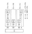
図11は、制御情報の間欠受信を説明する図である。図11によると、通信装置は、nのグループに分けられており、グループごとに制御信号を受信するスロット位置が決められている。図11の通信装置1は、G1の位置でのみ制御信号を受信し、通信装置2は、G3の位置でのみ制御信号の受信を行っている。通信装置は、電源投入時等にランダムアクセスチャネルにより移動通信システムへ接続要求を行い、移動通信システムからの応答を受けて待ち受け状態に移行するが、このとき移動通信システムからグループの通知、すなわち、制御信号の受信スロット位置の通知も受ける。各通信装置は、自装置が受信すべきスロット位置以外の期間は、端末制御に必要な回路のみに電源供給を行い、受信回路等には電源供給を行わないことで消費電力の低減を行っている。
FIG. 11 is a diagram illustrating intermittent reception of control information. According to FIG. 11, the communication devices are divided into n groups, and the slot position for receiving the control signal is determined for each group. The
また、1のグループには複数の通信装置が属することとなるが、移動通信システム側から特定の通信装置に宛てた制御情報を制御信号により送信する場合、宛先である通信装置のアドレスといった識別子を明示して送信を行う。尚、間欠受信を行うためにはフレーム構成が完全同期式である必要がある。 In addition, a plurality of communication devices belong to one group, but when transmitting control information addressed to a specific communication device from the mobile communication system side by a control signal, an identifier such as the address of the communication device that is the destination is set. Explicitly send. In order to perform intermittent reception, the frame configuration needs to be completely synchronous.
通信装置が、移動通信システムの基地局と、直接無線信号の送受信を行うのではなく、他の通信装置を経由して制御情報等の送受信を行うマルチホップネットワークについて、現在検討が行われている。図12にマルチホップネットワークの構成図を示す。図12において、BS(Base Station)は基地局であり、MS(Mobile Station)及びRS(Repeater Station)は通信装置である。MSとRSとの違いは、通信装置が他の通信装置のための中継を行っているか否かであり、装置そのものは同一である。以後、中継動作を行っている通信装置を中継装置又はRSと、中継動作を行っていない通信装置を移動装置又はMSと表現する。 Currently, a multi-hop network in which a communication device does not directly transmit / receive radio signals to / from a base station of a mobile communication system but transmits / receives control information or the like via another communication device is currently being studied. . FIG. 12 shows a configuration diagram of the multi-hop network. In FIG. 12, BS (Base Station) is a base station, and MS (Mobile Station) and RS (Repeator Station) are communication devices. The difference between the MS and the RS is whether or not the communication device is relaying for another communication device, and the device itself is the same. Hereinafter, a communication device performing a relay operation is expressed as a relay device or RS, and a communication device not performing a relay operation is expressed as a mobile device or MS.
図12のグループBは、通信装置が、音声及び/又はデータを送受するトラヒックチャネルと、制御情報を送受する制御チャネルを基地局との間で直接設定する、従来からのシングルホップ通信での構成を示している。この場合通信装置は、基地局の通信エリア内に存在する必要がある。 Group B in FIG. 12 is a conventional single-hop communication configuration in which a communication device directly sets a traffic channel for transmitting and receiving voice and / or data and a control channel for transmitting and receiving control information. Is shown. In this case, the communication device needs to exist in the communication area of the base station.
図12のグループAは、MSが基地局の通信エリア外に存在する場合に用いられる。MSは、基地局側、すなわち上流側に位置するRSとトラヒックチャネル及び制御チャネルを設定し、基地局とRSが設定しているトラヒックチャネル及び制御チャネルを使用して、基地局と音声等のトラヒックと、制御情報の送受信を行う。 Group A in FIG. 12 is used when the MS exists outside the communication area of the base station. The MS sets the RS, traffic channel, and control channel located on the base station side, that is, the upstream side, and uses the traffic channel and control channel set by the base station and the RS to use the traffic such as voice to the base station. Control information is transmitted and received.
図12のグループCは、トラヒックチャネルに対しては、マルチホップ通信を適用し、制御チャネルに対してはシングルホップ通信を適用する構成を示している。本構成においては、トラヒックチャネルの通信距離を短く刻むことで、トラヒックチャネルで高速な通信を行うことが可能となる。通信距離を短くすると伝播損失が小さくなり、その結果、受信装置での受信電力が大きくなり、よって、1ビット当たりのエネルギー対雑音電力密度比Eb/N0が大きくなるためである。一方、制御チャネルで伝送される情報量は少なく、制御チャネルの伝送速度は低速でもよいため、シングルホップ接続としている。 Group C in FIG. 12 shows a configuration in which multi-hop communication is applied to the traffic channel and single-hop communication is applied to the control channel. In this configuration, by shortening the communication distance of the traffic channel, it becomes possible to perform high-speed communication on the traffic channel. This is because if the communication distance is shortened, the propagation loss is reduced, and as a result, the received power at the receiving apparatus is increased, and thus the energy-to-noise power density ratio Eb / N0 per bit is increased. On the other hand, since the amount of information transmitted through the control channel is small and the transmission rate of the control channel may be low, a single-hop connection is used.
また、移動通信システムのマルチホップネットワークと類似するシステムとして、無線LANシステムのアドホックネットワークがある。無線LAN(Local Area Network)システムでは、BSS(Basic Service Set)とIBSS(Independent Basic Service Set)という2つのネットワーク構成が定義されており、このうちIBSSがアドホックネットワークと呼ばれるものである(非特許文献1参照)。 As a system similar to a multi-hop network of a mobile communication system, there is an ad hoc network of a wireless LAN system. In a wireless LAN (Local Area Network) system, two network configurations, BSS (Basic Service Set) and IBSS (Independent Basic Service Set), are defined, of which IBSS is called an ad hoc network (non-patent literature). 1).
アドホックネットワークでは、最初にアドホックネットワークを開設した通信装置が制御信号の1つであるビーコンを送信し、他の通信装置は、ビーコンの受信により既存の通信装置を認識しネットワークの確立を行う。ビーコンの送信間隔は、最初にアドホックネットワークを開設した通信装置が決定する。 In an ad hoc network, a communication device that first establishes an ad hoc network transmits a beacon that is one of control signals, and other communication devices recognize existing communication devices by receiving beacons and establish a network. The beacon transmission interval is determined by the communication apparatus that first established the ad hoc network.
無線LANにおいては、パワー管理機能についての規定もある。図13は、アドホックネットワークでのパワー管理機能を説明する図である。図13の通信装置1は、最初にアドホックネットワークを開設した通信装置であり、自身が決定したビーコン間隔に基づきビーコンを送信している。ビーコン間隔は、全通信装置が受信状態となるATIM(Announcement Traffic Indication Message)ウインドウ期間と、通信中の通信装置以外は、受信を行わず電力消費を防ぐDoze期間とに分けられている。他の通信装置にデータ送信を行いたい通信装置は、ATIMウインドウ期間中にATIMパケットを送信し、目的の通信装置にデータ送信を行う旨を通知する。図13においては、通信装置2が通信装置3にATIMパケットの送信を行っている。通信装置2及び3は、ATIMウインドウ期間経過後も、Doze状態とはならず、パケットの送受信を行う。
In the wireless LAN, there is also a regulation for a power management function. FIG. 13 is a diagram illustrating a power management function in an ad hoc network. The
マルチホップネットワークで、基地局と他の通信装置との中継を行う通信装置が、基地局からの周期的な制御信号の全スロットを常に受信し、中継する構成は、商用電源で動作する通信装置ならともかく、電池により動作する移動通信システム向けの通信装置では、消費電力の観点から難しく、従って、中継を行う通信装置であっても図11に示すような間欠動作を適用する必要がある。図12のグループCのように、トラヒックチャネルがマルチホップ構成であっても、制御チャネルがシングルホップ構成である場合には、移動装置は、基地局との制御チャネルにより、基地局から適当な中継装置の情報を取得し、或いは、基地局が制御チャネルを使用して中継装置に、移動装置の情報を与えることで、中継装置との間にトラヒックチャネルを確立する構成とすることが考えられる。 A communication device that relays between a base station and another communication device in a multi-hop network always receives and relays all slots of a periodic control signal from the base station. In any case, a communication device for a mobile communication system that is operated by a battery is difficult from the viewpoint of power consumption. Therefore, even a communication device that performs relay needs to apply an intermittent operation as shown in FIG. Even if the traffic channel has a multi-hop configuration as shown in group C in FIG. 12, if the control channel has a single-hop configuration, the mobile device performs appropriate relaying from the base station using the control channel with the base station. It is conceivable that a traffic channel is established between the base station and the relay device by acquiring the information of the device or by giving the mobile device information to the relay device using a control channel.
しかし、図12のグループAのように、制御チャネルもマルチホップ通信としなければならない状況下においては、通信装置が、基地局と接続し、基地局からの制御情報を間欠受信している他の通信装置を見つけ、前記他の通信装置との間に制御チャネルを確立し、確立した制御チャネルにより基地局と制御情報の送受信を行う手段が必要となる。 However, in a situation where the control channel must also be multi-hop communication as in group A in FIG. 12, the communication device is connected to the base station and receives other control information intermittently from the base station. A means for finding a communication device, establishing a control channel with the other communication device, and transmitting / receiving control information with the base station using the established control channel is required.
無線LANにおいてはビーコンを使用して、ATIMウイドウ内で、他の通信装置にATIMパケットを送信することで、間欠受信による消費電力削減と、通信装置間の接続の確立を両立させているが、ビーコンの送信は、他の装置が存在しない場合にも行われ、結果、不要な干渉を増大させる恐れがあり、また、定期的にビーコンを送信することで消費電力の削減にも一定の限界が生じることになる。従って、本構成を、中継装置と移動装置間での制御チャネルの確立に適用してもその効果は限定的なものとなる。 In a wireless LAN, using a beacon and transmitting ATIM packets to other communication devices within the ATIM window, both power consumption reduction by intermittent reception and establishment of connection between communication devices are achieved. Beacons are transmitted even when there is no other device. As a result, unnecessary interference may increase, and there is a certain limit to reducing power consumption by transmitting beacons periodically. Will occur. Therefore, even if this configuration is applied to establishment of a control channel between the relay device and the mobile device, the effect is limited.
従って、本発明は、基地局とのマルチホップ接続において、消費電力を増大させず、不要な干渉を抑え、基地局への接続のために中継可能な通信装置の存在を認識し、認識した通信装置経由で基地局と接続する通信装置及び基地局への接続方法を提供することを目的とする。 Therefore, the present invention recognizes the existence of a communication device capable of relaying for connection to a base station without increasing power consumption, suppressing unnecessary interference in a multi-hop connection with a base station, and recognizing the recognized communication. It is an object of the present invention to provide a communication apparatus that connects to a base station via the apparatus and a connection method to the base station.
本発明における通信装置によれば、
基地局とマルチホップで接続する通信装置であって、第1の制御チャネルで送信され、複数の時間スロットからなる制御信号のうち、所定のスロットのみを受信する第1の受信手段と、第1の制御信号の前記所定のスロットの情報を、自装置経由で基地局に接続する通信装置に中継する中継手段と、第2の制御チャネルに信号を送信する送信手段と、第1の受信手段での受信時に、第2の制御チャネルを受信する第2の受信手段とを有し、中継手段による中継は、第2の制御チャネルでの信号の送受信に基づき開始することを特徴とする。
According to the communication device of the present invention,
A communication device connected to a base station by multi-hop, wherein a first receiving means for receiving only a predetermined slot among control signals transmitted by a first control channel and comprising a plurality of time slots; A relay unit that relays the information of the predetermined slot of the control signal to a communication device connected to the base station via the own device, a transmission unit that transmits a signal to the second control channel, and a first reception unit. And receiving the second control channel, and relaying by the relaying unit is started based on transmission / reception of a signal on the second control channel.
本発明の通信装置における他の実施形態によれば、
第2の受信手段による自装置の識別子を含む接続要求の受信により、中継手段は、中継を開始することも好ましい。
According to another embodiment of the communication device of the present invention,
It is also preferable that the relay unit starts relaying by receiving the connection request including the identifier of the own device by the second receiving unit.
また、本発明の通信装置における他の実施形態によれば、
第2の受信手段が、装置の識別子を含まない接続要求を受信した場合には、送信手段は、前記接続要求の受信からランダムな待ち時間後に、自装置の識別子を含む接続応答を送信することも好ましい。
According to another embodiment of the communication device of the present invention,
When the second receiving unit receives a connection request that does not include the device identifier, the transmitting unit transmits a connection response including the identifier of the own device after a random waiting time from the reception of the connection request. Is also preferable.
更に、本発明の通信装置における他の実施形態によれば、
中継手段は、自装置経由で基地局に接続する通信装置宛ての情報がある場合のみ中継を行うことも好ましい。
Furthermore, according to another embodiment of the communication device of the present invention,
It is also preferable that the relay means relays only when there is information addressed to the communication device connected to the base station via its own device.
更に、本発明の通信装置における他の実施形態によれば、
第2の受信手段は、送信手段が接続要求を送信している間も、第2の制御チャネルの受信を行い、他の通信装置からの接続応答により、他の通信装置が中継する制御信号のスロット位置を認識し、第1の受信手段は、前記認識したスロット位置を前記所定のスロット位置として制御信号の受信を行うことも好ましい。
Furthermore, according to another embodiment of the communication device of the present invention,
The second receiving means receives the second control channel even while the transmitting means is transmitting a connection request, and receives a control signal relayed by another communication apparatus in response to a connection response from the other communication apparatus. It is also preferable that the first receiving means recognizes the slot position and receives the control signal with the recognized slot position as the predetermined slot position.
更に、本発明の通信装置における他の実施形態によれば、
送信手段は、接続要求の送信電力を、制御信号の時間スロットを単位として、第2の受信手段による接続応答の受信まで増加させることも好ましい。
Furthermore, according to another embodiment of the communication device of the present invention,
Preferably, the transmission means increases the transmission power of the connection request until reception of the connection response by the second reception means in units of time slots of the control signal.
本発明におけるマルチホップによる基地局への接続方法によれば、
複数の時間スロットからなり、基地局が第1の制御チャネルで送信する制御信号の所定のスロットのみを受信し、前記所定のスロットを受信しているときに、第2の制御チャネルも受信するように構成された第1の通信装置を経由して、第2の通信装置が基地局と接続する方法であって、第2の通信装置が、第2の制御チャネルに接続要求を連続して送信するステップと、第1の通信装置が、接続要求に対して、第2の制御チャネルに接続応答を送信するステップと、第2の通信装置が、接続応答により、第1の通信装置が中継する制御信号のスロット位置を認識するステップと、第1の通信装置が、受信する制御信号の中継を開始するステップと、第2の通信装置が、前記認識したスロット位置に基づき、第1の通信装置が中継する制御信号を受信するステップとを有することを特徴とする。
According to the connection method to the base station by multi-hop in the present invention,
It is composed of a plurality of time slots, and receives only a predetermined slot of a control signal transmitted from the base station through the first control channel, and receives the second control channel when receiving the predetermined slot. The second communication device is connected to the base station via the first communication device configured as described above, and the second communication device continuously transmits a connection request to the second control channel. The first communication device transmits a connection response to the second control channel in response to the connection request, and the second communication device relays the first communication device according to the connection response. A step of recognizing a slot position of the control signal, a step of the first communication apparatus starting relaying of the received control signal, and a second communication apparatus based on the recognized slot position of the first communication apparatus; Control signal relayed by Characterized by a step of receiving.
基地局との制御信号の中継を行う通信装置は、基地局からの制御信号の受信スロットと同じ時間だけ第2の受信手段による受信動作を行えばよく、また、自装置の受信スロットのみ中継を行えばよいため電源寿命を延ばすことができる。 The communication device that relays the control signal with the base station only needs to perform the reception operation by the second receiving means for the same time as the reception slot of the control signal from the base station, and relays only the reception slot of its own device. This can extend the life of the power supply.
自装置経由で基地局に接続する通信装置宛ての情報がある場合のみ中継を行うことで、
中継を行っている装置からの不要な信号の送信を止めて干渉を低減し、かつ、制御信号の中継頻度の低減により電池寿命を延ばすことを可能とする。
By relaying only when there is information addressed to the communication device connected to the base station via its own device,
It is possible to reduce the interference by stopping the transmission of unnecessary signals from the relaying device, and to extend the battery life by reducing the frequency of relaying the control signal.
送信手段は、接続要求の送信電力を、制御信号の時間スロットを単位として、第2の受信手段による接続応答の受信まで増加させることで、最適な送信電力を設定する。 The transmission means sets the optimum transmission power by increasing the transmission power of the connection request until reception of the connection response by the second reception means in units of time slots of the control signal.
本発明を実施するための最良の実施形態について、以下では図面を用いて詳細に説明する。以下の説明において、上述したように、基地局はBSとも表現し、中継動作を行っている(又は行うことになる)通信装置を、中継装置又はRSと表現し、中継動作を行っていない(又は行うこととならない)通信装置を、移動装置又はMSと表現する。しかしながらRSとMSは、その動作状態を区別するための便宜的なもので、装置としては同じものである。 The best mode for carrying out the present invention will be described in detail below with reference to the drawings. In the following description, as described above, a base station is also expressed as a BS, and a communication device that performs (or will perform) a relay operation is expressed as a relay device or RS and does not perform a relay operation ( A communication device (or that will not be performed) is expressed as a mobile device or MS. However, RS and MS are convenient for distinguishing their operating states, and are the same devices.
図1は、基地局と通信装置の報知チャネルによる制御信号の送受信タイミングを示す図である。図1に示すように、報知チャネルによる制御信号は、複数の時間スロットからなり、周期的に送信されるフレームで構成され、フレーム周期が各通信装置における間欠受信周期と一致している。このフレームはシステム内で既知であり、本発明による中継装置はフレーム毎に、つまり、間欠受信周期毎に、自装置が受信すべきスロット位置の信号を受信する。尚、中継装置が受信すべきスロット位置は、中継装置からのランダムアクセスチャネルによる基地局への接続要求をトリガとする、中継装置と基地局との接続処理の際に、基地局より他の制御チャネルを用いて通知されたものである。 FIG. 1 is a diagram illustrating transmission / reception timings of control signals using a broadcast channel between a base station and a communication apparatus. As shown in FIG. 1, the control signal by the broadcast channel is composed of a plurality of time slots and is composed of periodically transmitted frames, and the frame period coincides with the intermittent reception period in each communication device. This frame is known in the system, and the relay device according to the present invention receives a signal at a slot position that the device itself should receive every frame, that is, every intermittent reception cycle. The slot position to be received by the relay device is controlled by the base station during the connection process between the relay device and the base station, triggered by a connection request from the relay device to the base station via the random access channel. This is notified using the channel.
図2は、図1の状態から、移動装置が中継装置を経由して基地局と通信する方法を説明する図である。中継装置は、基地局からの報知チャネルによる制御信号を受信している間、同時にランダムアクセスチャネルを受信する構成とする。そして、移動装置は、ランダムアクセスチャネルにより、システム内で既知の接続要求を連続して送信する。制御信号である接続要求の送信期間は、最大でも、中継装置が報知チャネルを受信する周期である間欠受信周期であり、中継装置はランダムアクセスチャネルからの接続要求を受信した場合は、ランダムな待ち時間後に、自装置の識別子を含む接続応答をランダムアクセスチャネルにより、マルチホップ接続の下流側に位置することとなる移動装置に送信する。ここで、ランダムな待ち時間を設けるのは、複数の中継装置からの応答により信号が衝突するのを防止するためである。 FIG. 2 is a diagram illustrating a method in which the mobile device communicates with the base station via the relay device from the state of FIG. The relay device is configured to simultaneously receive the random access channel while receiving the control signal using the broadcast channel from the base station. Then, the mobile device continuously transmits connection requests known in the system using a random access channel. The transmission period of the connection request that is a control signal is at most an intermittent reception period that is a period in which the relay apparatus receives the broadcast channel. When the relay apparatus receives a connection request from the random access channel, the transmission period is a random waiting period. After a time, a connection response including the identifier of the own device is transmitted to the mobile device that will be located downstream of the multi-hop connection by a random access channel. Here, the reason for providing a random waiting time is to prevent signals from colliding due to responses from a plurality of relay apparatuses.
ランダムアクセスチャネルは、既に説明した通り、通信装置の電源投入時等に、通信装置が基地局に接続要求を行うためのものであり、通信装置が基地局と接続して待ち受け状態に移行した後、通信装置はランダムアクセスチャネルを使用しない。従って、待ち受け状態にある通信装置が、基地局からの報知チャネルを受信している間、同時にランダムアクセスチャネルを受信する構成とすることによる既存システムとの矛盾は生じない。 As described above, the random access channel is used when the communication device makes a connection request to the base station when the communication device is turned on. After the communication device connects to the base station and enters the standby state, The communication device does not use a random access channel. Therefore, there is no inconsistency with the existing system by adopting a configuration in which the communication apparatus in the standby state receives the random access channel at the same time while receiving the broadcast channel from the base station.
報知チャネルとランダムアクセスチャネルの同時受信については、現在の代表的な移動通信システムであるCDMA方式を例にすると、異なる拡散符号を使用することで、同一周波数で同一時間に送信された信号の識別が可能であり、本構成を実現することについての問題はない。 For simultaneous reception of the broadcast channel and the random access channel, for example, in the case of a CDMA system which is a typical mobile communication system, by using different spreading codes, it is possible to identify signals transmitted at the same frequency and at the same time. There is no problem with realizing this configuration.
制御信号である接続応答を受信した移動装置は、接続要求の送信を止めて、使用する中継装置の選択、すなわち、複数の中継装置から接続応答を受信した場合に備え、使用する1の中継装置の決定手順を開始する。選択は、選択した中継装置の識別子を含む接続要求を、選択した中継装置の受信タイミングに合わせて送信することにより行う。選択した中継装置が、再度接続応答を送信することで中継装置と移動装置間の接続が完了し、以後、中継装置は、基地局との報知チャネルの中継を開始する。中継装置が移動装置への報知チャネルの中継に使用する無線リソースは、基地局と中継装置間と同一のものを使用しても、異なるものを使用しても良い。尚、中継装置の選択基準は任意である。また、中継装置は、受信する接続要求に装置の識別子が含まれているか否かにより、1回目、つまり中継可能な装置を調べるための接続要求であるか、2回目、つまり中継装置の選択のための接続要求であるかを判断する。 The mobile device that has received the connection response that is a control signal stops transmission of the connection request and selects one relay device to be used, that is, one relay device to be used in preparation for receiving connection responses from a plurality of relay devices. Start the decision procedure. The selection is performed by transmitting a connection request including the identifier of the selected relay device in accordance with the reception timing of the selected relay device. The selected relay device transmits a connection response again to complete the connection between the relay device and the mobile device. Thereafter, the relay device starts relaying the broadcast channel with the base station. The radio resources used by the relay device for relaying the broadcast channel to the mobile device may be the same or different between the base station and the relay device. Note that the selection criterion for the relay device is arbitrary. Further, the relay device determines whether the connection request is for the first time, that is, a device for checking a device that can be relayed, or for the second time, that is, the selection of the relay device, depending on whether the received connection request includes the device identifier. It is determined whether the request is for connection.
図3は、移動装置が行う接続要求の送信電力制御を示す図である。移動装置は、各スロット内では、最小の送信電力から開始し、中継装置からの応答がない場合は、徐々に送信電力を増加させていく。中継装置から応答信号を受信した場合は、その時点での送信電力を以後の通信において使用する。図3では、送信電力を3段階で変化させる例が示されている。 FIG. 3 is a diagram illustrating transmission power control of a connection request performed by a mobile device. The mobile device starts from the minimum transmission power within each slot, and gradually increases the transmission power when there is no response from the relay device. When a response signal is received from the relay device, the transmission power at that time is used in subsequent communications. FIG. 3 shows an example in which the transmission power is changed in three stages.
図4は、移動装置での接続処理フロー図であり、図5は、中継装置での接続処理フロー図である。 FIG. 4 is a connection processing flowchart in the mobile device, and FIG. 5 is a connection processing flowchart in the relay device.
尚、中継装置と移動装置間の接続完了後、中継装置は、基地局から報知チャネルにより受信する制御信号の中継を開始するが、常に中継を行うのではなく、配下の移動装置に宛てた制御情報がある場合に限り中継を行う構成とする利点がある。図6は、中継装置が保持する現在接続中である移動装置の情報を示す図である。図6に示すように、制御信号の中継を、常時必要とする通信装置がある場合には、中継を行い、それ以外の通信装置には、当該通信装置宛ての制御情報がある場合のみ中継を行う。但し、情報の有無に係らず、通信装置は基地局の間欠受信周期に同期する必要があるため、定期的に制御信号を中継することが必要である。図6においては、64又は128スロット毎に制御信号を中継することとなっている。以上、中継装置からの不要な信号の送信を止めることで、干渉を低減し、かつ、電池寿命を延ばすことを可能としている。 After the connection between the relay device and the mobile device is completed, the relay device starts relaying the control signal received from the base station through the broadcast channel. However, the relay device does not always relay, but controls the mobile device under its control. There is an advantage that relaying is performed only when there is information. FIG. 6 is a diagram illustrating information on a mobile device currently connected to the relay device. As shown in FIG. 6, when there is a communication device that always needs to relay control signals, relay is performed, and other communication devices relay only when there is control information addressed to the communication device. Do. However, regardless of the presence or absence of information, the communication device needs to synchronize with the intermittent reception cycle of the base station, so it is necessary to periodically relay the control signal. In FIG. 6, the control signal is relayed every 64 or 128 slots. As described above, by stopping transmission of unnecessary signals from the relay device, it is possible to reduce interference and extend battery life.
図7は、中継装置が常に中継を行う場合のシーケンス図であり、図8は、移動装置宛ての情報がある場合にのみ中継を行う場合のシーケンス図である。また、以上の接続方法は、マルチホップの段数が大きくなっても使用できる。図9に、基地局−中継装置1−中継装置2−移動装置という3ホップでの接続のシーケンス図を示す。 FIG. 7 is a sequence diagram when the relay device always relays, and FIG. 8 is a sequence diagram when relay is performed only when there is information destined for the mobile device. The above connection method can be used even when the number of multi-hop stages is large. FIG. 9 shows a sequence diagram of connection in three hops: base station-relay apparatus 1-relay apparatus 2-mobile apparatus.
以上、下りリンクの制御信号の中継について説明を行ってきたが、通信中のトラヒックの流れについて補足する。移動装置と基地局間での通信が始まると、中継装置は、常時電源がON状態となり、移動装置と基地局間でのトラヒックの中継を行う。移動装置と基地局間での通信が終了すると、中継装置は再び間欠受信状態となる。 As described above, the relay of the downlink control signal has been described, but the flow of traffic during communication will be supplemented. When communication between the mobile device and the base station starts, the relay device is always turned on, and relays traffic between the mobile device and the base station. When the communication between the mobile device and the base station is completed, the relay device is again in the intermittent reception state.
次に、移動装置が移動して接続経路が変わる場合について説明する。この場合、最初に確立した経路で移動通信システムに接続している。この状態では、移動装置は、確立中の経路を用いて移動通信システム側から周辺にある基地局や、中継装置の情報を受信することができる。本手法は、従来の移動通信システムで採用されている手法であり、本発明の通信システムに対しても適用することができる。よって、ハンドオーバ時には、次に接続する中継装置の受信タイミングに合わせて接続要求信号を送信すれば良い。 Next, a case where the mobile device moves and the connection route changes will be described. In this case, the mobile communication system is connected to the first established route. In this state, the mobile device can receive information on base stations and relay devices in the vicinity from the mobile communication system side using the established path. This technique is a technique adopted in a conventional mobile communication system, and can also be applied to the communication system of the present invention. Therefore, at the time of handover, the connection request signal may be transmitted in accordance with the reception timing of the relay device to be connected next.
図10は、本発明の通信装置のブロック図である。アンテナ1が受信した無線信号は、デュプレクサ2を介して受信部3に入力される。デュプレクサ2は、送信信号と受信信号を分離するためのものである。受信信号は、復調部5で復調されて、報知チャネル処理部7、ランダムアクセスチャネル処理部8、更には、他チャネル処理部9として表現している、各チャネルの処理部に入力され、それぞれのチャネルの内容に応じた処理が行われる。送信側については、各チャネル処理部で処理された信号は、変調部6に入力されて、変調処理が行われ、送信部4で所定の電力に増幅された後、送信される。
FIG. 10 is a block diagram of the communication apparatus of the present invention. A radio signal received by the
間欠受信制御部11は、受信部3での受信タイミングの制御を行い、送信電力制御部12は、通信相手や通信環境に応じた送信電力の制御を行う。
The intermittent
この他、送受信タイミングや相手端末の識別子を記憶する記憶部13や、ディスプレイ等の表示部14、テンキー等の操作部15、メッセージ表示や入力を受け付ける入出力部16を有する。これらは、主制御部10の制御の元に動作する。例えば、基地局からの無線信号を受信し、復調後のメッセージが通信装置の呼出しである場合は、入出力部16を介して利用者に呼出し通知を行い、呼出し通知に対して利用者が通信装置の操作部15を操作して応答すると通信が始まる。また、移動通信システムからの同報メッセージの場合は、必要に応じてその情報が記憶部13に記憶される。記憶部13は、図6に示す様な、配下に接続する通信装置の情報を保存するためにも用いられる。
In addition, it has a
1 アンテナ
2 デュプレクサ
3 受信部
4 送信部
5 復調部
6 変調部
7 報知チャネル処理部
8 ランダムアクセスチャネル処理部
9 他チャネル処理部
10 主制御部
11 間欠受信制御部
12 送信電力制御部
13 記憶部
14 表示部
15 操作部
16 入出力部
DESCRIPTION OF
Claims (7)
第1の制御チャネルで送信され、複数の時間スロットからなる制御信号のうち、所定のスロットのみを受信する第1の受信手段と、
第1の制御信号の前記所定のスロットの情報を、自装置経由で基地局に接続する通信装置に中継する中継手段と、
第2の制御チャネルに信号を送信する送信手段と、
第1の受信手段での受信時に、第2の制御チャネルを受信する第2の受信手段とを有し、
中継手段による中継は、第2の制御チャネルでの信号の送受信に基づき開始すること、
を特徴とする通信装置。 A communication device that connects to a base station via multi-hop,
First receiving means for transmitting only a predetermined slot out of a control signal composed of a plurality of time slots and transmitted through a first control channel;
Relay means for relaying information of the predetermined slot of the first control signal to a communication device connected to the base station via the own device;
Transmitting means for transmitting a signal to the second control channel;
A second receiving means for receiving the second control channel at the time of reception by the first receiving means;
Relaying by the relay means starts based on transmission / reception of a signal on the second control channel;
A communication device characterized by the above.
送信手段は、前記接続要求の受信からランダムな待ち時間後に、自装置の識別子を含む接続応答を送信することを特徴とする請求項2に記載の通信装置。 When the second receiving means receives a connection request that does not include the device identifier,
3. The communication apparatus according to claim 2, wherein the transmission unit transmits a connection response including an identifier of the own apparatus after a random waiting time from reception of the connection request.
第1の受信手段は、前記認識したスロット位置を前記所定のスロット位置として制御信号の受信を行うことを特徴とする請求項1から4のいずれか1項に記載の通信装置。 The second receiving means receives the second control channel even while the transmitting means is transmitting a connection request, and receives a control signal relayed by another communication apparatus in response to a connection response from the other communication apparatus. Recognize slot position,
5. The communication apparatus according to claim 1, wherein the first receiving unit receives a control signal using the recognized slot position as the predetermined slot position. 6.
第2の通信装置が、第2の制御チャネルに接続要求を連続して送信するステップと、
第1の通信装置が、接続要求に対して、第2の制御チャネルに接続応答を送信するステップと、
第2の通信装置が、接続応答により、第1の通信装置が中継する制御信号のスロット位置を認識するステップと、
第1の通信装置が、受信する制御信号の中継を開始するステップと、
第2の通信装置が、前記認識したスロット位置に基づき、第1の通信装置が中継する制御信号を受信するステップと、
を有することを特徴とする方法。
It consists of a plurality of time slots, receives only a predetermined slot of the control signal transmitted by the base station on the first control channel, and receives the second control channel when receiving the predetermined slot The second communication device is connected to the base station via the first communication device configured as described above,
A second communication device continuously transmitting a connection request to the second control channel;
The first communication device transmits a connection response to the second control channel in response to the connection request;
A second communication device recognizing a slot position of a control signal relayed by the first communication device by a connection response;
The first communication device starts relaying the received control signal;
A second communication device receiving a control signal relayed by the first communication device based on the recognized slot position;
A method characterized by comprising:
Priority Applications (1)
| Application Number | Priority Date | Filing Date | Title |
|---|---|---|---|
| JP2005068728A JP4534807B2 (en) | 2005-03-11 | 2005-03-11 | Communication device and multi-hop connection method to base station |
Applications Claiming Priority (1)
| Application Number | Priority Date | Filing Date | Title |
|---|---|---|---|
| JP2005068728A JP4534807B2 (en) | 2005-03-11 | 2005-03-11 | Communication device and multi-hop connection method to base station |
Publications (2)
| Publication Number | Publication Date |
|---|---|
| JP2006254155A true JP2006254155A (en) | 2006-09-21 |
| JP4534807B2 JP4534807B2 (en) | 2010-09-01 |
Family
ID=37094153
Family Applications (1)
| Application Number | Title | Priority Date | Filing Date |
|---|---|---|---|
| JP2005068728A Expired - Fee Related JP4534807B2 (en) | 2005-03-11 | 2005-03-11 | Communication device and multi-hop connection method to base station |
Country Status (1)
| Country | Link |
|---|---|
| JP (1) | JP4534807B2 (en) |
Cited By (11)
| Publication number | Priority date | Publication date | Assignee | Title |
|---|---|---|---|---|
| JP2009061256A (en) * | 2007-08-10 | 2009-03-26 | Fujifilm Corp | Radiation image capturing system, and method of setting transmission radio field intensity in the system |
| EP2106174A2 (en) | 2008-03-28 | 2009-09-30 | Fujitsu Ltd. | Relay station, radio communication system, and control method of relay station |
| EP2234289A2 (en) | 2009-03-25 | 2010-09-29 | Fujitsu Limited | Relay method and relay station |
| JP2010226325A (en) * | 2009-03-23 | 2010-10-07 | Anritsu Networks Kk | Radio network system communication method and radio communication device |
| JP2010283664A (en) * | 2009-06-05 | 2010-12-16 | Hitachi Ltd | Wireless communication system, and wireless communication apparatus |
| WO2011010515A1 (en) * | 2009-07-23 | 2011-01-27 | ソニー株式会社 | Communication system, communication control method, mobile terminal, and relay device |
| JP2012510782A (en) * | 2008-12-01 | 2012-05-10 | クゥアルコム・インコーポレイテッド | Random access channel procedures in wireless communication systems with repeaters |
| CN101286780B (en) * | 2007-04-12 | 2012-10-03 | 华为技术有限公司 | System and method for implementing relay transmission |
| JP2012195970A (en) * | 2012-07-09 | 2012-10-11 | Fujitsu Ltd | Wireless communication apparatus |
| US8867427B2 (en) | 2008-07-10 | 2014-10-21 | Samsung Electronics Co., Ltd. | Communication system using hierarchical modulation scheme or network coding scheme |
| US9282522B2 (en) | 2013-09-10 | 2016-03-08 | Kabushiki Kaisha Toshiba | Communication apparatus and communication method |
Citations (3)
| Publication number | Priority date | Publication date | Assignee | Title |
|---|---|---|---|---|
| JPH10224287A (en) * | 1997-02-06 | 1998-08-21 | Teranetsuto Prod:Kk | Communication processing system for mobile object communication |
| JP2001103024A (en) * | 1999-09-29 | 2001-04-13 | Fujitsu Ltd | Digital radio equipment, digital radio communication system, digital radio transmitter and digital radio communicating method |
| JP2003188803A (en) * | 2001-12-20 | 2003-07-04 | Nec Saitama Ltd | Method for avoiding calling disabled state due to time slot error |
-
2005
- 2005-03-11 JP JP2005068728A patent/JP4534807B2/en not_active Expired - Fee Related
Patent Citations (3)
| Publication number | Priority date | Publication date | Assignee | Title |
|---|---|---|---|---|
| JPH10224287A (en) * | 1997-02-06 | 1998-08-21 | Teranetsuto Prod:Kk | Communication processing system for mobile object communication |
| JP2001103024A (en) * | 1999-09-29 | 2001-04-13 | Fujitsu Ltd | Digital radio equipment, digital radio communication system, digital radio transmitter and digital radio communicating method |
| JP2003188803A (en) * | 2001-12-20 | 2003-07-04 | Nec Saitama Ltd | Method for avoiding calling disabled state due to time slot error |
Cited By (21)
| Publication number | Priority date | Publication date | Assignee | Title |
|---|---|---|---|---|
| CN101286780B (en) * | 2007-04-12 | 2012-10-03 | 华为技术有限公司 | System and method for implementing relay transmission |
| JP2009061256A (en) * | 2007-08-10 | 2009-03-26 | Fujifilm Corp | Radiation image capturing system, and method of setting transmission radio field intensity in the system |
| EP2106174A2 (en) | 2008-03-28 | 2009-09-30 | Fujitsu Ltd. | Relay station, radio communication system, and control method of relay station |
| US8401463B2 (en) | 2008-03-28 | 2013-03-19 | Fujitsu Limited | Relay station, radio communication system, and control method of relay station |
| US8867427B2 (en) | 2008-07-10 | 2014-10-21 | Samsung Electronics Co., Ltd. | Communication system using hierarchical modulation scheme or network coding scheme |
| US9125217B2 (en) | 2008-12-01 | 2015-09-01 | Qualcomm Incorporated | Blank subframe uplink design |
| US8879461B2 (en) | 2008-12-01 | 2014-11-04 | Qualcomm Incorporated | Blank subframe uplink design |
| JP2012510782A (en) * | 2008-12-01 | 2012-05-10 | クゥアルコム・インコーポレイテッド | Random access channel procedures in wireless communication systems with repeaters |
| JP2010226325A (en) * | 2009-03-23 | 2010-10-07 | Anritsu Networks Kk | Radio network system communication method and radio communication device |
| US8335467B2 (en) | 2009-03-25 | 2012-12-18 | Fujitsu Limited | Relay method and relay station |
| EP2234289A2 (en) | 2009-03-25 | 2010-09-29 | Fujitsu Limited | Relay method and relay station |
| JP2010283664A (en) * | 2009-06-05 | 2010-12-16 | Hitachi Ltd | Wireless communication system, and wireless communication apparatus |
| JP2011029851A (en) * | 2009-07-23 | 2011-02-10 | Sony Corp | Communication system, communication control method, mobile terminal, and relay device |
| WO2011010515A1 (en) * | 2009-07-23 | 2011-01-27 | ソニー株式会社 | Communication system, communication control method, mobile terminal, and relay device |
| US8983556B2 (en) | 2009-07-23 | 2015-03-17 | Sony Corporation | Determining a communication device to be used from one or more communication devices having a power save mode |
| US9191096B2 (en) | 2009-07-23 | 2015-11-17 | Sony Corporation | Communication system, communication control method, mobile terminal, and relay device |
| CN105262532A (en) * | 2009-07-23 | 2016-01-20 | 索尼公司 | Communication system, communication control method, mobile terminal, and relay device |
| US10200174B2 (en) | 2009-07-23 | 2019-02-05 | Sony Corporation | Communication system, communication control method, mobile terminal and relay device |
| CN105262532B (en) * | 2009-07-23 | 2019-12-13 | 索尼公司 | Communication system, communication control method, mobile terminal and relay device |
| JP2012195970A (en) * | 2012-07-09 | 2012-10-11 | Fujitsu Ltd | Wireless communication apparatus |
| US9282522B2 (en) | 2013-09-10 | 2016-03-08 | Kabushiki Kaisha Toshiba | Communication apparatus and communication method |
Also Published As
| Publication number | Publication date |
|---|---|
| JP4534807B2 (en) | 2010-09-01 |
Similar Documents
| Publication | Publication Date | Title |
|---|---|---|
| JP4534807B2 (en) | Communication device and multi-hop connection method to base station | |
| US7058419B2 (en) | Method and apparatus for reducing communication latency in a wireless group call | |
| US8160048B2 (en) | Method for accessing hybrid network, and gateway apparatus, wireless terminal and communication system thereof | |
| US8320288B2 (en) | Communication system, communication apparatus and communication method, and computer program | |
| US8401463B2 (en) | Relay station, radio communication system, and control method of relay station | |
| JP4921492B2 (en) | Apparatus and method for supporting relay service in multi-hop relay broadband wireless access communication system | |
| US8938197B2 (en) | Base station aided mobile-relay candidate pre-selection and pre-deployment | |
| EP2161945B1 (en) | A method for terminating connection to wireless relay station | |
| KR101347089B1 (en) | Method and apparatus for implementing relay | |
| JP4630368B2 (en) | Signal relay system and method in communication system | |
| US20190364503A1 (en) | Power-save mode for wireless device | |
| WO2010050533A1 (en) | Wireless communication system, wireless communication method, wireless communication terminal device, relay device, and relay system | |
| KR20090010696A (en) | Apparatus and method for controlling power in wireless communication system using relay | |
| GB2436661A (en) | Method of operation in a wireless communication system and a client node, an infrastructure node and system | |
| JP2006121696A (en) | Communication system and traffic transmission method thereof | |
| CN113347645A (en) | 802.11 wireless multi-hop communication and self-adaptive switching method | |
| JP2008066827A (en) | Connection destination selecting method of relay station applied with ieee802.16, relay station, and program | |
| JP4496336B2 (en) | Packet transmission method in wireless multi-hop network | |
| JP5997661B2 (en) | Repeater device and repeater sleep control method | |
| Janefalkar et al. | Cellular ad-hoc relay for emergencies (CARE) | |
| JP2012195970A (en) | Wireless communication apparatus | |
| KR20120071113A (en) | Relay method of terminal for communicaion of emergency terminal in mobile communication system | |
| WO2023199229A1 (en) | Power saving modes of operation for network-controlled repeaters | |
| CN117097435A (en) | Data processing method, device, communication equipment, system and storage medium | |
| KR20120074242A (en) | Method for configuration cell by multi mode terminal |
Legal Events
| Date | Code | Title | Description |
|---|---|---|---|
| A621 | Written request for application examination |
Free format text: JAPANESE INTERMEDIATE CODE: A621 Effective date: 20070919 |
|
| A977 | Report on retrieval |
Free format text: JAPANESE INTERMEDIATE CODE: A971007 Effective date: 20100219 |
|
| A131 | Notification of reasons for refusal |
Free format text: JAPANESE INTERMEDIATE CODE: A131 Effective date: 20100302 |
|
| A521 | Request for written amendment filed |
Free format text: JAPANESE INTERMEDIATE CODE: A523 Effective date: 20100416 |
|
| TRDD | Decision of grant or rejection written | ||
| A01 | Written decision to grant a patent or to grant a registration (utility model) |
Free format text: JAPANESE INTERMEDIATE CODE: A01 Effective date: 20100525 |
|
| A01 | Written decision to grant a patent or to grant a registration (utility model) |
Free format text: JAPANESE INTERMEDIATE CODE: A01 |
|
| A61 | First payment of annual fees (during grant procedure) |
Free format text: JAPANESE INTERMEDIATE CODE: A61 Effective date: 20100607 |
|
| FPAY | Renewal fee payment (event date is renewal date of database) |
Free format text: PAYMENT UNTIL: 20130625 Year of fee payment: 3 |
|
| R150 | Certificate of patent or registration of utility model |
Ref document number: 4534807 Country of ref document: JP Free format text: JAPANESE INTERMEDIATE CODE: R150 Free format text: JAPANESE INTERMEDIATE CODE: R150 |
|
| LAPS | Cancellation because of no payment of annual fees |