JP2006246306A - Projector and its control method - Google Patents
Projector and its control method Download PDFInfo
- Publication number
- JP2006246306A JP2006246306A JP2005062013A JP2005062013A JP2006246306A JP 2006246306 A JP2006246306 A JP 2006246306A JP 2005062013 A JP2005062013 A JP 2005062013A JP 2005062013 A JP2005062013 A JP 2005062013A JP 2006246306 A JP2006246306 A JP 2006246306A
- Authority
- JP
- Japan
- Prior art keywords
- region
- image
- optical image
- forming
- projector
- Prior art date
- Legal status (The legal status is an assumption and is not a legal conclusion. Google has not performed a legal analysis and makes no representation as to the accuracy of the status listed.)
- Withdrawn
Links
Images


Classifications
-
- H—ELECTRICITY
- H04—ELECTRIC COMMUNICATION TECHNIQUE
- H04N—PICTORIAL COMMUNICATION, e.g. TELEVISION
- H04N9/00—Details of colour television systems
- H04N9/12—Picture reproducers
- H04N9/31—Projection devices for colour picture display, e.g. using electronic spatial light modulators [ESLM]
- H04N9/3179—Video signal processing therefor
-
- G—PHYSICS
- G03—PHOTOGRAPHY; CINEMATOGRAPHY; ANALOGOUS TECHNIQUES USING WAVES OTHER THAN OPTICAL WAVES; ELECTROGRAPHY; HOLOGRAPHY
- G03B—APPARATUS OR ARRANGEMENTS FOR TAKING PHOTOGRAPHS OR FOR PROJECTING OR VIEWING THEM; APPARATUS OR ARRANGEMENTS EMPLOYING ANALOGOUS TECHNIQUES USING WAVES OTHER THAN OPTICAL WAVES; ACCESSORIES THEREFOR
- G03B21/00—Projectors or projection-type viewers; Accessories therefor
- G03B21/005—Projectors using an electronic spatial light modulator but not peculiar thereto
-
- G—PHYSICS
- G03—PHOTOGRAPHY; CINEMATOGRAPHY; ANALOGOUS TECHNIQUES USING WAVES OTHER THAN OPTICAL WAVES; ELECTROGRAPHY; HOLOGRAPHY
- G03B—APPARATUS OR ARRANGEMENTS FOR TAKING PHOTOGRAPHS OR FOR PROJECTING OR VIEWING THEM; APPARATUS OR ARRANGEMENTS EMPLOYING ANALOGOUS TECHNIQUES USING WAVES OTHER THAN OPTICAL WAVES; ACCESSORIES THEREFOR
- G03B21/00—Projectors or projection-type viewers; Accessories therefor
- G03B21/14—Details
-
- H—ELECTRICITY
- H04—ELECTRIC COMMUNICATION TECHNIQUE
- H04N—PICTORIAL COMMUNICATION, e.g. TELEVISION
- H04N5/00—Details of television systems
- H04N5/74—Projection arrangements for image reproduction, e.g. using eidophor
-
- H—ELECTRICITY
- H04—ELECTRIC COMMUNICATION TECHNIQUE
- H04N—PICTORIAL COMMUNICATION, e.g. TELEVISION
- H04N9/00—Details of colour television systems
- H04N9/12—Picture reproducers
- H04N9/31—Projection devices for colour picture display, e.g. using electronic spatial light modulators [ESLM]
- H04N9/3102—Projection devices for colour picture display, e.g. using electronic spatial light modulators [ESLM] using two-dimensional electronic spatial light modulators
- H04N9/3105—Projection devices for colour picture display, e.g. using electronic spatial light modulators [ESLM] using two-dimensional electronic spatial light modulators for displaying all colours simultaneously, e.g. by using two or more electronic spatial light modulators
-
- H—ELECTRICITY
- H04—ELECTRIC COMMUNICATION TECHNIQUE
- H04N—PICTORIAL COMMUNICATION, e.g. TELEVISION
- H04N5/00—Details of television systems
- H04N5/74—Projection arrangements for image reproduction, e.g. using eidophor
- H04N5/7416—Projection arrangements for image reproduction, e.g. using eidophor involving the use of a spatial light modulator, e.g. a light valve, controlled by a video signal
- H04N5/7441—Projection arrangements for image reproduction, e.g. using eidophor involving the use of a spatial light modulator, e.g. a light valve, controlled by a video signal the modulator being an array of liquid crystal cells
- H04N2005/745—Control circuits therefor
-
- H—ELECTRICITY
- H04—ELECTRIC COMMUNICATION TECHNIQUE
- H04N—PICTORIAL COMMUNICATION, e.g. TELEVISION
- H04N21/00—Selective content distribution, e.g. interactive television or video on demand [VOD]
- H04N21/40—Client devices specifically adapted for the reception of or interaction with content, e.g. set-top-box [STB]; Operations thereof
- H04N21/47—End-user applications
- H04N21/485—End-user interface for client configuration
Abstract
Description
本発明は、画像信号を入力し、前記画像信号に応じた光学像を投写するプロジェクタ及びその制御方法に関する。 The present invention relates to a projector that inputs an image signal and projects an optical image corresponding to the image signal, and a control method therefor.
光源から射出された光を、光変調装置により画像信号に応じて変調して光学像を形成し、この光学像を投写レンズにてスクリーン上に拡大投写するプロジェクタが知られている(例えば、特許文献1参照)。
特許文献1に記載のプロジェクタは、ユーザの操作によるズーム指定等に基づいて、投写される画像のサイズを電子ズーム機能(レンズではなく電子回路を利用して画面のサイズ調整を行うもの)を用いて調整可能になっている。
電子ズーム機能は、入力した画像信号に所定の処理を施し、光変調装置における光学像を形成可能な領域(変調可能領域)内で、画像信号に応じた光学像を形成する領域(形成領域)のサイズを変更して、スクリーン上に投写される投写画像のサイズを変更可能とするものであり、光変調装置における変調可能領域の所定の位置(例えば、中心位置)を基準として、形成領域を拡大又は縮小するようになっている。
There is known a projector that modulates light emitted from a light source in accordance with an image signal by a light modulation device to form an optical image, and enlarges and projects this optical image on a screen by a projection lens (for example, patents). Reference 1).
The projector described in
The electronic zoom function performs predetermined processing on the input image signal, and forms an optical image corresponding to the image signal (formation area) within an area where the optical image can be formed in the light modulation device (modulable area). The size of the projected image projected on the screen can be changed by changing the size of the image forming area, and the formation area is determined based on a predetermined position (for example, the center position) of the modifiable area in the light modulation device. It is designed to expand or contract.
特許文献1に記載のプロジェクタでは、光変調装置における変調可能領域の中心位置を基準にして形成領域が拡大又は縮小するようになっている。このため、投写画像の中心位置とスクリーンの中心位置とが略合致するようにプロジェクタを設置した状態で、電子ズーム機能により形成領域を拡大又は縮小すると、投写画像は、スクリーンの中心位置を基準にして拡大又は縮小される。
しかしながら、一旦、投写画像の中心位置がスクリーンの中心位置に対してずれてしまうと、電子ズーム機能により投写画像を拡大した際に、本来ならスクリーンに投写可能な画像サイズであっても、画像の一部がスクリーンから外れてしまうことになり、拡大可能な画像サイズが制限されてしまう。このため、再度、中心位置同士を合わせるために、プロジェクタの設置状態を調整し直さなければならいという問題が生じてしまう。
In the projector described in
However, once the center position of the projected image deviates from the center position of the screen, when the projected image is enlarged by the electronic zoom function, even if the image size can be projected onto the screen originally, A part of the image will come off the screen, and the image size that can be enlarged is limited. For this reason, in order to align the center positions again, there arises a problem that the installation state of the projector must be readjusted.
本発明は上記問題を鑑みてなされたものであり、その目的は、投写画像の位置を容易に変更可能とするプロジェクタ及びその制御方法を提供することにある。 SUMMARY An advantage of some aspects of the invention is that it provides a projector that can easily change the position of a projected image and a control method thereof.
本発明のプロジェクタは、画像信号を入力し、前記画像信号に応じた光学像を投写して、投写面に画像を表示するプロジェクタであって、光を変調可能な変調可能領域を有し、光源から射出された光を前記変調可能領域で変調して光学像を形成する光変調装置と、前記光変調装置で形成された光学像を拡大投写する投写レンズと、前記変調可能領域内で前記画像信号に応じた光学像を形成するための形成領域のサイズ又は形状を変更可能な形成領域変更手段と、前記画像信号に応じた光学像の投写位置を表す位置情報を入力可能な操作部と、前記形成領域変更手段によってサイズ又は形状が変更された前記形成領域が前記変調可能領域内を移動可能な場合に、前記操作部から入力した前記位置情報に基づいて前記形成領域を移動させる形成領域移動手段とを備えることを特徴とする。 The projector of the present invention is a projector that inputs an image signal, projects an optical image corresponding to the image signal, and displays the image on a projection surface, and has a modifiable region capable of modulating light, and a light source A light modulator that modulates the light emitted from the light in the modulatable region to form an optical image, a projection lens that magnifies and projects the optical image formed by the light modulator, and the image in the modulatable region A forming region changing unit capable of changing the size or shape of a forming region for forming an optical image according to a signal, an operation unit capable of inputting position information indicating a projection position of the optical image according to the image signal, A formation region that moves the formation region based on the position information input from the operation unit when the formation region whose size or shape has been changed by the formation region changer is movable in the modifiable region. Characterized in that it comprises a moving means.
このプロジェクタによれば、形成領域変更手段によってサイズ又は形状が変更された形成領域が、変調可能領域内を移動可能な場合に、操作部から入力した位置情報に基づいて、形成領域を移動させる形成領域移動手段を備えているため、操作部の操作によって光学像の投写位置を変更させることが可能となる。この結果、投写画像の位置を容易に変更することが可能となる。 According to the projector, when the formation area whose size or shape has been changed by the formation area changing unit is movable in the modifiable area, the formation area is moved based on the position information input from the operation unit. Since the area moving means is provided, the projection position of the optical image can be changed by operating the operation unit. As a result, the position of the projected image can be easily changed.
このプロジェクタにおいて、前記形成領域変更手段で前記形成領域のサイズ又は形状を変更することによって、前記形成領域が前記変調可能領域内を移動可能となった場合に、前記画像信号に応じた光学像の投写位置が変更可能である旨を通知する通知手段を備えることが望ましい。 In this projector, when the formation region can be moved in the modifiable region by changing the size or shape of the formation region by the formation region changing means, an optical image corresponding to the image signal is changed. It is desirable to provide notification means for notifying that the projection position can be changed.
このプロジェクタによれば、形成領域が変調可能領域内を移動可能となった場合に、その旨を通知する通知手段を備えているため、投写画像が移動可能であることを容易に認識することが可能となる。 According to this projector, when the formation area becomes movable within the modifiable area, the projector is provided with notification means for notifying the fact that the projection image can be easily recognized as being movable. It becomes possible.
このプロジェクタにおいて、前記通知手段は、投写画像に通知内容を合成して表示することが望ましい。 In this projector, it is desirable that the notification means synthesizes and displays the notification content on the projected image.
このプロジェクタによれば、投写画像に通知内容を合成して表示するため、投写画像から目を離すことなく通知内容を認識することが可能となる。 According to this projector, since the notification content is combined with the projected image and displayed, it is possible to recognize the notification content without keeping an eye on the projection image.
本発明のプロジェクタは、画像信号を入力し、前記画像信号に応じた光学像を投写して、投写面に画像を表示するプロジェクタであって、光を変調可能な変調可能領域を有し、光源から射出された光を前記変調可能領域で変調して光学像を形成する光変調装置と、前記光変調装置で形成された光学像を拡大投写する投写レンズと、前記変調可能領域内で前記画像信号に応じた光学像を形成するための形成領域のサイズ又は形状を変更可能な形成領域変更手段と、前記画像信号に応じた光学像の投写位置を表す位置情報を入力可能な操作部と、前記形成領域変更手段によってサイズ又は形状が変更された前記形成領域が前記変調可能領域内を移動可能な場合に、前記画像信号に応じた光学像の投写位置が変更可能である旨を通知するとともに前記位置情報の入力を促す通知手段と、前記操作部によって入力された前記位置情報に基づいて、前記形成領域を移動させる形成領域移動手段とを備えることを特徴とする。 The projector of the present invention is a projector that inputs an image signal, projects an optical image corresponding to the image signal, and displays the image on a projection surface, and has a modifiable region capable of modulating light, and a light source A light modulator that modulates the light emitted from the light in the modulatable region to form an optical image, a projection lens that magnifies and projects the optical image formed by the light modulator, and the image in the modulatable region A forming region changing unit capable of changing the size or shape of a forming region for forming an optical image according to a signal, an operation unit capable of inputting position information indicating a projection position of the optical image according to the image signal, Notifying that the projection position of the optical image according to the image signal can be changed when the formation area whose size or shape has been changed by the formation area changing means is movable in the modifiable area. in front And notifying means for prompting the input of the position information, based on the positional information inputted by the operating unit, characterized in that it comprises a forming area moving means for moving the forming region.
このプロジェクタによれば、形成領域変更手段が形成領域のサイズ又は形状を変更した結果、形成領域が変調可能領域内を移動可能である場合に、形成領域移動手段による形成領域の移動を行うために、通知手段によって位置情報の入力を促す通知を行っている。このため、形成領域のサイズ又は形状の変更と、形成領域の移動とを連続して行うことが可能となり、投写画像の位置を変更する際の利便性が向上する。 According to the projector, when the formation region can be moved within the modifiable region as a result of the formation region changing unit changing the size or shape of the formation region, the formation region moving unit can move the formation region. The notification means prompts the input of the position information by the notification means. For this reason, it is possible to continuously change the size or shape of the formation region and move the formation region, and the convenience when changing the position of the projected image is improved.
このプロジェクタにおいて、前記通知手段は、投写画像に通知内容を合成して表示することが望ましい。 In this projector, it is desirable that the notification means synthesizes and displays the notification content on the projected image.
このプロジェクタによれば、投写画像に通知内容を合成して表示するため、投写画像から目を離すことなく通知内容を認識することが可能となる。 According to this projector, since the notification content is combined with the projected image and displayed, it is possible to recognize the notification content without keeping an eye on the projection image.
このプロジェクタにおいて、前記形成領域変更手段によってサイズ又は形状が変更された前記形成領域が前記変調可能領域内を移動可能な場合に、前記画像信号に応じた光学像が移動可能な位置又は方向を通知する案内手段を有することが望ましい。 In this projector, when the forming area whose size or shape has been changed by the forming area changing means is movable within the modifiable area, the position or direction in which the optical image corresponding to the image signal can be moved is notified. It is desirable to have guiding means to do this.
このプロジェクタによれば、形成領域を移動可能な位置又は方向を通知する案内手段を有しているため、移動可能な位置や方向を認識することが容易になり、投写画像の位置を変更する際の利便性がさらに向上する。 According to this projector, since the guide means for notifying the position or direction in which the formation area can be moved is provided, it is easy to recognize the position and direction in which the movement is possible, and when changing the position of the projected image The convenience is further improved.
このプロジェクタにおいて、前記案内手段は、投写画像に通知内容を合成して表示することが望ましい。 In this projector, it is desirable that the guiding means synthesizes and displays the notification contents on the projected image.
このプロジェクタによれば、投写画像に通知内容を合成して表示するため、投写画像から目を離すことなく通知内容を認識することが可能となる。 According to this projector, since the notification content is combined with the projected image and displayed, it is possible to recognize the notification content without keeping an eye on the projection image.
本発明のプロジェクタは、画像信号を入力し、前記画像信号に応じた光学像を投写して、投写面に画像を表示するプロジェクタであって、光を変調可能な変調可能領域を有し、光源から射出された光を前記変調可能領域で変調して光学像を形成する光変調装置と、前記光変調装置で形成された光学像を拡大投写する投写レンズと、前記画像信号に応じた光学像のサイズ又は形状を表すサイズ情報、及び当該光学像の投写位置を表す位置情報を入力可能な操作部と、前記操作部によって入力された前記サイズ情報に応じて、前記変調可能領域内で前記画像信号に応じた光学像を形成するための形成領域のサイズ又は形状を変更する形成領域変更手段と、前記形成領域変更手段によってサイズ又は形状が変更された前記形成領域が前記変調可能領域内を移動可能な場合に、前記画像信号に応じた光学像の投写位置が変更可能である旨を通知して前記位置情報の入力を促す通知手段と、前記操作部によって入力された前記位置情報に基づいて、前記形成領域を移動させる形成領域移動手段とを備えることを特徴とする。 The projector of the present invention is a projector that inputs an image signal, projects an optical image corresponding to the image signal, and displays the image on a projection surface, and has a modifiable region capable of modulating light, and a light source A light modulation device that modulates the light emitted from the light in the modulatable region to form an optical image, a projection lens that magnifies and projects the optical image formed by the light modulation device, and an optical image corresponding to the image signal An operation unit capable of inputting size information indicating the size or shape of the image and position information indicating the projection position of the optical image, and the image within the modifiable region in accordance with the size information input by the operation unit. Forming region changing means for changing the size or shape of a forming region for forming an optical image in accordance with a signal; and the forming region whose size or shape has been changed by the forming region changing means A notification means for notifying that the projection position of the optical image can be changed according to the image signal and prompting the input of the position information, and the position information input by the operation unit And a formation region moving means for moving the formation region.
このプロジェクタによれば、操作部から入力されたサイズ情報に基づいて形成領域変更手段が形成領域のサイズ又は形状を変更した結果、形成領域が変調可能領域内を移動可能である場合に、形成領域移動手段による形成領域の移動を行うために、通知手段によって位置情報の入力を促す通知を行っている。このため、投写画像の位置の変更を、投写画像のサイズ・形状変更と連続して行うことが可能となり、投写画像の位置を変更する際の利便性が向上する。 According to this projector, when the formation area is movable within the modifiable area as a result of the formation area changing unit changing the size or shape of the formation area based on the size information input from the operation unit, the formation area In order to move the formation area by the moving means, notification for prompting input of position information is performed by the notifying means. For this reason, the change of the position of the projection image can be performed continuously with the change of the size and shape of the projection image, and the convenience in changing the position of the projection image is improved.
本発明のプロジェクタの制御方法は、光を変調可能な変調可能領域を有し、光源から射出された光を前記変調可能領域で変調して光学像を形成する光変調装置と、前記光変調装置で形成された光学像を拡大投写する投写レンズとを備え、入力した画像信号に応じた光学像を投写して、投写面に画像を表示するプロジェクタの制御方法であって、前記変調可能領域内で前記画像信号に応じた光学像を形成するための形成領域のサイズ又は形状を変更する形成領域変更工程と、前記画像信号に応じた光学像の投写位置を表す位置情報を入力する位置情報入力工程と、前記形成領域変更工程にてサイズ又は形状が変更された前記形成領域が前記変調可能領域内を移動可能な場合に、前記位置情報入力工程にて入力した前記位置情報に基づいて前記形成領域を移動させる形成領域移動工程とを備えることを特徴とする。 The projector control method of the present invention includes a light modulation device that has a modulatable region capable of modulating light, modulates light emitted from a light source in the modulatable region, and forms an optical image, and the light modulation device And a projection lens for enlarging and projecting the optical image formed in step (b), projecting an optical image corresponding to the input image signal, and displaying the image on a projection surface. And a position information input for inputting position information indicating a projection position of the optical image according to the image signal, and a formation area changing step for changing the size or shape of the formation area for forming the optical image according to the image signal. And when the formation region whose size or shape has been changed in the formation region change step is movable in the modifiable region, the shape is based on the position information input in the position information input step. Characterized in that it comprises a forming area moving step of moving region.
このプロジェクタの制御方法によれば、形成領域変更工程にてサイズ又は形状が変更された形成領域が、変調可能領域内を移動可能な場合に、位置情報入力工程にて入力した位置情報に基づいて、形成領域を移動させる形成領域移動工程を備えているため、位置情報の入力操作によって光学像の投写位置を変更させることが可能となる。この結果、投写画像の位置を容易に変更することが可能となる。 According to this projector control method, when the formation area whose size or shape has been changed in the formation area change process is movable within the modifiable area, it is based on the position information input in the position information input process. Since the formation region moving step for moving the formation region is provided, the projection position of the optical image can be changed by the input operation of the position information. As a result, the position of the projected image can be easily changed.
本発明のプロジェクタの制御方法は、光を変調可能な変調可能領域を有し、光源から射出された光を前記変調可能領域で変調して光学像を形成する光変調装置と、前記光変調装置で形成された光学像を拡大投写する投写レンズとを備え、入力した画像信号に応じた光学像を投写して、投写面に画像を表示するプロジェクタの制御方法であって、前記変調可能領域内で前記画像信号に応じた光学像を形成するための形成領域のサイズ又は形状を変更する形成領域変更工程と、前記形成領域変更工程にてサイズ又は形状が変更された前記形成領域が前記変調可能領域内を移動可能な場合に、前記画像信号に応じた光学像の投写位置が変更可能である旨を通知するとともに、前記投写位置を表す位置情報の入力を促す通知工程と、前記位置情報を入力する位置情報入力工程と、前記位置情報入力工程にて入力された前記位置情報に基づいて、前記形成領域を移動させる形成領域移動工程とを備えることを特徴とする。 The projector control method of the present invention includes a light modulation device that has a modulatable region capable of modulating light, modulates light emitted from a light source in the modulatable region, and forms an optical image, and the light modulation device And a projection lens for enlarging and projecting the optical image formed in step (b), projecting an optical image corresponding to the input image signal, and displaying the image on a projection surface. The forming region changing step for changing the size or shape of the forming region for forming the optical image according to the image signal and the forming region whose size or shape has been changed in the forming region changing step can be modulated. A notification step for notifying that the projection position of the optical image can be changed in accordance with the image signal, and for prompting input of position information representing the projection position, when the position information is movable; Enter A position information input step of, based on the positional information inputted by said position information input step, characterized in that it comprises a forming area moving step of moving the forming region.
このプロジェクタの制御方法によれば、形成領域変更工程にて形成領域のサイズ又は形状を変更した結果、形成領域が変調可能領域内を移動可能である場合に、形成領域移動工程での形成領域の移動を行うために、位置情報の入力を促す通知を行っている。このため、形成領域のサイズ又は形状の変更と、形成領域の移動とを連続して行うことが可能となり、投写画像の位置を変更する際の利便性が向上する。 According to this projector control method, as a result of changing the size or shape of the formation region in the formation region change step, if the formation region can move within the modifiable region, In order to move, a notification prompting input of position information is performed. For this reason, it is possible to continuously change the size or shape of the formation region and move the formation region, and the convenience when changing the position of the projected image is improved.
本発明のプロジェクタの制御方法は、光を変調可能な変調可能領域を有し、光源から射出された光を前記変調可能領域で変調して光学像を形成する光変調装置と、前記光変調装置で形成された光学像を拡大投写する投写レンズとを備え、入力した画像信号に応じた光学像を投写して、投写面に画像を表示するプロジェクタの制御方法であって、前記画像信号に応じた光学像のサイズ又は形状を表すサイズ情報を入力するサイズ情報入力工程と、前記サイズ情報入力工程にて入力された前記サイズ情報に応じて、前記変調可能領域内で前記画像信号に応じた光学像を形成するための形成領域のサイズ又は形状を変更する形成領域変更工程と、前記形成領域変更工程にてサイズ又は形状が変更された前記形成領域が前記変調可能領域内を移動可能な場合に、前記画像信号に応じた光学像の投写位置が変更可能である旨を通知するとともに、前記投写位置を表す位置情報の入力を促す通知工程と、前記位置情報を入力する位置情報入力工程と、前記位置情報入力工程にて入力された前記位置情報に基づいて、前記形成領域を移動させる形成領域移動工程とを備えることを特徴とする。 The projector control method of the present invention includes a light modulation device that has a modulatable region capable of modulating light, modulates light emitted from a light source in the modulatable region, and forms an optical image, and the light modulation device And a projection lens for enlarging and projecting the optical image formed in step (b), projecting the optical image according to the input image signal, and displaying the image on the projection surface, the control method according to the image signal A size information input step for inputting size information representing the size or shape of the optical image, and an optical in accordance with the image signal in the modifiable region in accordance with the size information input in the size information input step. A forming region changing step for changing the size or shape of a forming region for forming an image, and the forming region whose size or shape has been changed in the forming region changing step can move within the modifiable region. A notification step for notifying that the projection position of the optical image according to the image signal can be changed, and for prompting input of position information indicating the projection position, and a position information input step for inputting the position information. And a formation region moving step of moving the formation region based on the position information input in the position information input step.
このプロジェクタの制御方法によれば、入力されたサイズ情報に基づいて、形成領域のサイズ又は形状を変更した結果、形成領域が変調可能領域内を移動可能である場合に、形成領域移動工程での形成領域の移動を行うために、位置情報の入力を促す通知を行っている。このため、投写画像の位置の変更を、投写画像のサイズ・形状変更と連続して行うことが可能となり、投写画像の位置を変更する際の利便性が向上する。 According to this projector control method, when the formation region is movable within the modifiable region as a result of changing the size or shape of the formation region based on the input size information, In order to move the formation area, notification for prompting input of position information is performed. For this reason, the change of the position of the projection image can be performed continuously with the change of the size and shape of the projection image, and the convenience in changing the position of the projection image is improved.
また、上述したプロジェクタ及びその制御方法がプロジェクタに備えられたコンピュータ(CPU)を用いて構築されている場合には、本発明は、その機能を実現するためのプログラム、或いは当該プログラムを前記コンピュータで読み取り可能に記録した記録媒体等の態様で構成することも可能である。記録媒体としては、フレキシブルディスクやCD−ROM、光磁気ディスク、ICカード、ROMカートリッジ、パンチカード、バーコード等の符号が印刷された印刷物、プロジェクタの内部記憶装置(RAMやROM等のメモリ)、及び外部記憶装置等、前記コンピュータが読み取り可能な種々の媒体を利用することができる。 Further, when the projector described above and its control method are constructed using a computer (CPU) provided in the projector, the present invention provides a program for realizing the function, or the program is executed by the computer. It is also possible to configure in the form of a readable recording medium or the like. As recording media, flexible disks, CD-ROMs, magneto-optical disks, IC cards, ROM cartridges, punch cards, printed matter on which codes such as barcodes are printed, projector internal storage devices (memory such as RAM and ROM), Various media that can be read by the computer, such as an external storage device, can be used.
以下、本発明の実施形態に係るプロジェクタについて、図面を参照して説明する。
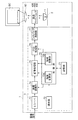
図1は、本実施形態に係るプロジェクタの概略構成を示すブロック図である。
本実施形態のプロジェクタ1は、光源から射出される光を、外部から入力される画像信号に応じて変調して光学像を形成し、形成した光学像をスクリーン上に拡大投写するものであり、図1に示すように、光学装置2と制御装置3とで構成されている。
Hereinafter, a projector according to an embodiment of the present invention will be described with reference to the drawings.
FIG. 1 is a block diagram illustrating a schematic configuration of a projector according to the present embodiment.
The
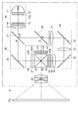
図2は、光学装置2の詳細を説明するための構成図であり、光源から射出された光が、スクリーンに至るまでの光路を示している。
図2に示すように、光学装置2は、照明光学系10と、色光分離光学系20と、リレー光学系30と、光変調装置としての3つの液晶ライトバルブ40R,40G,40Bと、クロスダイクロイックプリズム50と、投写レンズ60とを備えている。
FIG. 2 is a configuration diagram for explaining the details of the
As shown in FIG. 2, the
照明光学系10は、光源11と、第1のレンズアレイ12と、第2のレンズアレイ13と、偏光変換素子14と、重畳レンズ15とを備えており、光源11から射出された光線束は、微小なレンズ12aがマトリクス状に配置された第1のレンズアレイ12によって多数の微小な光線束に分割される。第2のレンズアレイ13及び重畳レンズ15は、分割された光線束のそれぞれが、照明対象である3つの液晶ライトバルブ40R,40G,40Bの全体を照射するように備えられている。このため、各光線束が液晶ライトバルブ40R,40G,40Bで重畳され、液晶ライトバルブ40R,40G,40Bの全体がほぼ均一に照明される。
The illumination
偏光変換素子14は、光源11からの非偏光な光を液晶ライトバルブ40R,40G,40Bで効率よく利用可能とするため、特定の偏光方向を有する偏光光に揃える機能を有している。照明光学系10を射出した偏光光は、色光分離光学系20に入射する。
The
色光分離光学系20は、照明光学系10から射出された光を、波長域の異なる3色の光に分離する。第1のダイクロイックミラー21は、略赤色の光を透過させるとともに、透過する光よりも短波長の光を反射する。第1のダイクロイックミラー21を透過した赤色光Rは、反射ミラー22で反射されて赤色光用の液晶ライトバルブ40Rを照明する。
The color light separation
第1のダイクロイックミラー21で反射された光のうち、緑色光Gは、第2のダイクロイックミラー23によって反射されて緑色光用の液晶ライトバルブ40Gを照明する。また、青色光Bは、第2のダイクロイックミラー23を透過し、リレー光学系30を通過して、青色光用の液晶ライトバルブ40Bを照明する。
Of the light reflected by the first
なお、青色光Bの経路は、他の色光の経路に比べて長くなってしまうことから、光線束の発散によって液晶ライトバルブ40Bへの照明効率が低下するのを抑制するために、青色光Bの経路には、リレー光学系30が設けられている。
In addition, since the path | route of blue light B becomes long compared with the path | route of other color lights, in order to suppress that the illumination efficiency to liquid crystal
リレー光学系30は、入射側レンズ31と、第1の反射ミラー32と、リレーレンズ33と、第2の反射ミラー34と、射出側レンズ35とを備えている。色光分離光学系20から射出した青色光Bは、入射側レンズ31によってリレーレンズ33の近傍で収束し、射出側レンズ35に向けて発散する。
The relay
液晶ライトバルブ40R,40G,40Bのそれぞれは、液晶パネル41と、入射側偏光板42と、射出側偏光板43とを備えており、入射した光を変調して画像(光学像)を形成する。
図3は、本実施形態の液晶ライトバルブ40R,40G,40Bの平面図である。
図3に示すように、液晶ライトバルブ40R,40G,40Bは、一対の透明基板間に液晶が封入された液晶パネル41を備えており、各透明基板の内面には、液晶に対して微小領域(画素41P)毎に駆動電圧を印加可能な透明電極(画素電極)が所定の領域(変調可能領域としての画素領域41A)内にマトリクス状に形成されている。なお、本実施形態の液晶ライトバルブ40R,40G,40Bは、画素領域41Aのアスペクト比(Ax:Ay)が4:3になっている。
Each of the liquid
FIG. 3 is a plan view of the liquid
As shown in FIG. 3, each of the liquid
図2に戻って、液晶パネル41の入射側表面及び射出側表面には、それぞれ入射側偏光板42及び射出側偏光板43が貼り付けられている。入射側偏光板42及び射出側偏光板43は、それぞれ特定の偏光方向の偏光光のみを透過可能であり、入射側偏光板42は、偏光変換素子14によって揃えられた偏光方向の偏光光を透過可能となっている。このため、各液晶ライトバルブ40R,40G,40Bに入射する各色光の大部分は入射側偏光板42を透過して、液晶パネル41に入射する。
Returning to FIG. 2, the incident-side
ここで、液晶パネル41の各画素41Pに、画像信号に応じた駆動電圧が印加されると、液晶パネル41の画素領域41Aに入射した光は、駆動電圧に応じて変調され、画素41P毎に異なる偏光方向を有した偏光光となる。この偏光光のうち、射出側偏光板43を透過可能な偏光成分のみが液晶ライトバルブ40R,40G,40Bから射出される。つまり、液晶ライトバルブ40R,40G,40Bが、画像信号に応じて、画素41P毎に異なる透過率で入射光を透過させることによって、階調を有する光学像が色光毎に形成される。液晶ライトバルブ40R,40G,40Bから射出した各色光からなる光学像は、クロスダイクロイックプリズム50に入射する。
Here, when a driving voltage corresponding to an image signal is applied to each
クロスダイクロイックプリズム50は、各液晶ライトバルブ40R,40G,40Bから射出された各色の光学像を、画素41P毎に合成してカラー画像を表す光学像を形成する。クロスダイクロイックプリズム50によって合成された光学像は、投写レンズ60によって拡大投写されて、スクリーンSC等に投写画像が表示される。
The cross
一方、図1に示すように、制御装置3は、制御部70と、記憶部71と、操作部72と、レシーバ73と、画質調整部74と、画像処理部75と、OSD(オンスクリーンディスプレイ)処理部76と、ライトバルブ駆動部77とを備えている。
On the other hand, as shown in FIG. 1, the control device 3 includes a
制御部70は、前記各部71,72,74〜76に接続されている。制御部70は、コンピュータとしてのCPU(Central Processing Unit)等により構成されており、記憶部71に記憶されている制御プログラムに従って、プロジェクタ1の動作を統括制御する。なお、制御部70には、画像処理部75に制御信号を出力して処理内容を指示可能な領域変更部70a及び領域移動部70bが備えられている。
The
記憶部71は、フラッシュROM(Read Only Memory)等のメモリによって構成され、前記制御プログラムを記憶するとともに、各種設定値等の記憶に用いられる。
The
操作部72には、電源のオン・オフや画質の調整等、プロジェクタ1に対して各種操作を行うためのスイッチやキー等が備えられており、ユーザが操作部72を操作すると、操作部72は、操作内容に応じた操作信号を制御部70に出力する。
The
レシーバ73は、外部の画像供給装置(図示せず)からアナログ又はデジタルの画像信号を入力し、各色(R,G,B)毎の階調を表す画像データに変換して画質調整部74に供給する。
The
画質調整部74は、制御部70からの指示に基づいて、入力した画像データに対して輝度、コントラスト、シャープネス、色合いの調整等を行い、画像処理部75に出力する。
The image
画像処理部75は、制御部70からの指示、即ち領域変更部70a及び領域移動部70bからの制御信号に基づいて、入力した画像データを変換し、液晶ライトバルブ40R,40G,40Bの各画素41Pに対応する階調値を導出することにより、全画素41Pの階調値からなる画像データを生成する。
The
ここで、領域変更部70aが出力する制御信号には、電子ズーム機能の拡縮率(ズーム倍率)を表す電子ズーム情報、投写画像のアスペクト比を表すアスペクト比情報、投写画像の台形歪を補正するための台形歪補正情報等からなるサイズ情報が含まれており、領域移動部70bが出力する制御信号には、光学像を投写する位置を表す位置情報が含まれている。
Here, the control signal output from the area changing unit 70a corrects electronic zoom information indicating the enlargement / reduction ratio (zoom magnification) of the electronic zoom function, aspect ratio information indicating the aspect ratio of the projected image, and trapezoidal distortion of the projected image. Size information including trapezoidal distortion correction information and the like is included, and the control signal output from the
画像処理部75は、前記サイズ情報に基づいて、液晶ライトバルブ40R,40G,40Bの画素領域41A内に、画像データに応じた画像を形成する領域(形成領域)のサイズや形状を変更することにより、電子ズーム機能、アスペクト比変更機能、台形歪補正機能を実現するとともに、前記位置情報に基づいて、前記形成領域の位置を画素領域41A内で移動させることにより、投写画像の位置を変更することが可能になっている。このため、領域変更部70aと画像処理部75とが、本発明の形成領域変更手段として機能し、領域移動部70bと画像処理部75とが、本発明の形成領域移動手段として機能する。
Based on the size information, the
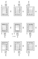
図4(a)〜(e)及び図5(a)〜(i)は、画像処理部75での処理を説明するための説明図である。ここで、図4は、サイズ情報に応じた処理を説明する説明図、図5は、位置情報に応じた処理を説明する説明図であり、いずれも図も、光源光の入射側正面から見た液晶ライトバルブ40R,40G,40Bを示している。
例えば、領域変更部70aからのサイズ情報が、電子ズームの拡縮率が最大値(100%)、アスペクト比が4:3、台形歪補正はなし、であることを示す場合には、画像処理部75は、画素領域41A全体を形成領域41Eとする(図4(a)参照)。
また、電子ズームの拡縮率が最大値未満の場合には、拡縮率(Ex/Ax)に応じた大きさの領域を形成領域41Eとし(図4(b)参照)、アスペクト比が16:9の場合には、アスペクト比(Ax:Ey)が16:9となる領域を形成領域41Eとする(図4(c)参照)。また、アスペクト比が4:3で台形歪補正を行う場合には、投写画像がアスペクト比4:3の矩形となるような台形形状の領域を形成領域41Eをとする(図4(d)参照)。なお、図4(e)は、電子ズームの拡縮率が最大値未満、アスペクト比が16:9で、台形歪補正を実施する場合の形成領域41Eを示している。
FIGS. 4A to 4E and FIGS. 5A to 5I are explanatory diagrams for explaining processing in the
For example, when the size information from the area changing unit 70a indicates that the enlargement / reduction ratio of the electronic zoom is the maximum value (100%), the aspect ratio is 4: 3, and the keystone distortion correction is not performed, the
When the enlargement / reduction ratio of the electronic zoom is less than the maximum value, an area having a size corresponding to the enlargement / reduction ratio (Ex / Ax) is defined as the
また、領域移動部70bからの位置情報は、画素領域41Aにおける形成領域41Eの位置を表すものであり、本実施形態では、図5(a)〜(i)に示すように、形成領域41Eの位置として、画素領域41AのX方向に3ヶ所、Y方向に3ヶ所の合計9(3×3)ヶ所のうちのいずれか1ヶ所を指定可能になっている。ここで、図5(e)は、形成領域41Eが画素領域41Aの中央に位置する状態を表している。図5(a)、(c)、(g)、(i)は、形成領域41Eが画素領域41Aの各角部に位置する状態であり、台形歪補正を行わない場合には、形成領域41Eの角部は、画素領域41Aの角部に一致する。図5(b)、(d)、(f)、(h)は、形成領域41Eが画素領域41Aの各辺に接するように位置する状態であり、台形歪補正を行わない場合には、形成領域41Eの一辺の中点が画素領域41Aの一辺の中点に一致する。
Further, the position information from the
上述したように、画像処理部75は、液晶ライトバルブ40R,40G,40Bの画素領域41A内に、形成領域41Eのサイズや形状、位置を定めた後、入力した画像データに対して間引き処理や補完処理を行って、形成領域41Eの各画素41Pに対応する階調値を生成する。また、画像の形成に寄与しない無効領域41N(画素領域41A内で形成領域41E以外の領域)の画素41Pの階調値を0(透過率が最小となる値)として、画素領域41A内の全画素41Pの階調値からなる画像データを生成し、生成した画像データをOSD処理部76に出力する。
As described above, the
OSD処理部76は、制御部70の指示により、メニュー画像やメッセージ画像等からなるOSD画像を、画像データに応じた画像(以下、「表示画像」という。)に重畳するための処理を行う。具体的には、OSD画像を表すOSD画像データを図示しないOSDメモリから読み出し、画像処理部75から入力した画像データにこのOSD画像データを合成した画像データを生成し、ライトバルブ駆動部77に出力する。なお、OSD画像を表示しない場合には、上記合成処理を行わないため、画像処理部75から出力される表示画像データが、そのままライトバルブ駆動部77に供給される。
The
ライトバルブ駆動部77は、OSD処理部76から入力した画像データに基づいて、液晶ライトバルブ40R,40G,40Bを駆動する。即ち、画素領域41Aの各画素41Pに、それぞれの階調値に応じた駆動電圧を印加することにより、液晶ライトバルブ40R,40G,40Bの形成領域41Eに画像を形成し、この液晶ライトバルブ40R,40G,40Bに光源の光が照射されると、スクリーンSC上に投写画像が表示される。
The light
図6(a)、(b)は、スクリーンSCに表示された投写画像を示す正面図であり、(a)は、電子ズームの拡縮率が100%の場合を示し、(b)は、拡縮率が100%未満の場合を示している。
電子ズームの拡縮率が最大値(100%)、アスペクト比が4:3、台形歪補正はなしの場合(図4(a)参照)には、画素領域41A全体が形成領域41Eであり、このとき、スクリーンSCには、図6(a)に示すように、画素領域41Aを透過した光の照射領域(以下、「投写領域GA」という。)の全体に表示画像GEが表示される。また、電子ズームの拡縮率が最大値未満の場合(図4(b)参照)には、図6(b)に示すように、投写領域GAよりも小さなサイズで表示画像GEが表示され、投写領域GA内で表示画像GEの外側の領域GNは、画素41Pの透過率が最小に設定された無効領域41Nに対応する領域であるため、ほとんど光が照射されない黒色領域となる。
6A and 6B are front views showing a projected image displayed on the screen SC, FIG. 6A shows a case where the enlargement / reduction ratio of the electronic zoom is 100%, and FIG. 6B shows the enlargement / reduction. The case where the rate is less than 100% is shown.
When the enlargement / reduction ratio of the electronic zoom is the maximum value (100%), the aspect ratio is 4: 3, and the keystone correction is not performed (see FIG. 4A), the
なお、上述した、電子ズーム機能、アスペクト比変更機能、台形歪補正機能は、いずれも、ユーザが操作部72を操作して指示することにより実行可能になっている。
Note that the electronic zoom function, the aspect ratio changing function, and the trapezoidal distortion correction function described above can be executed by the user operating the
次に、プロジェクタ1の動作について、図面を参照して説明する。本実施形態のプロジェクタ1は、操作部72からの操作信号に基づいて、電子ズーム、アスペクト比変更、台形歪補正等、形成領域41Eを変更する動作を行った結果、形成領域41Eが移動可能な状態である場合に、形成領域41E、即ち表示画像GEが移動可能である旨を通知してユーザに移動方向の入力を促す。さらに、この通知に応じて、ユーザが移動方向を指示すると、プロジェクタ1は、指示された方向に形成領域を移動させることにより表示画像GEの投写位置変更(以下、「画像シフト」という。)を行う。
Next, the operation of the
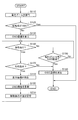
図7は、プロジェクタ1が電子ズーム機能を実行する際の動作を説明するフローチャートである。また、図8(a)、(b)及び図9(a)、(b)は、電子ズーム機能を実行する際に表示される投写画像を示す説明図である。プロジェクタ1が、例えば、画素領域41A全体で光学像を投写中、ユーザが操作部72を操作して、電子ズームを行う指示をすると、制御部70は、操作部72からの制御信号によりその旨を認識し、図7に示したフローに従って動作する。
FIG. 7 is a flowchart for explaining the operation when the
図7に示すように、ステップS110では、ユーザの指示に応じた電子ズーム機能を実行する。具体的には、制御部70は、OSD処理部76に指示をして、図8(a)に示すように、電子ズームを行うためのOSD画像GZを表示する。このOSD画像GZにより、ユーザは、表示画像GEのズーム状態(拡縮率)や、操作部72に備えられた「ワイド」キー及び「テレ」キーによりズーム状態を変更可能である旨を認識することができる。
As shown in FIG. 7, in step S110, an electronic zoom function according to a user instruction is executed. Specifically, the
ユーザが、前記OSD画像GZによる案内に従って、操作部72の「ワイド」キーや「テレ」キーを用いてズーム操作を行うと、制御部70は、領域変更部70aによって操作内容に応じた電子ズーム情報を画像処理部75に出力する。画像処理部75が当該電子ズーム情報に応じて形成領域41Eのサイズを変更することにより、表示画像GEは拡大又は縮小され、例えば、図8(b)に示すように、表示画像GEが投写領域GAに対して縮小されて表示される。ユーザは、表示画像GEが所望のサイズになるまで連続してズーム操作を行うことが可能であるが、所定時間(例えば、3秒程度)ズーム操作のない状態が続くと、制御部70は、ズーム操作が終了したと判断し、OSD画像GZの表示を終了してステップS120に移行する。
When the user performs a zoom operation using the “wide” key or the “tele” key of the
ステップS120では、制御部70は、ユーザによるズーム操作後のズーム状態(拡縮率)が100%か否かを判断する。ここで、拡縮率が100%の場合には、画素領域41A全体で画像を形成していることになり、形成領域41Eを移動させることができないため処理を終了する。ズーム操作後の拡縮率が100%未満の場合、つまり、形成領域41Eが画素領域41Aよりも小さい場合には、画素領域41A内で形成領域41Eが移動可能な状態であるため、ステップS130に移行して表示画像GEの投写位置を変更するための動作を行う。
In step S120, the
ステップS130では、制御部70は、OSD処理部76に指示をして、図9(a)に示すように、画像シフトをするためのOSD画像GMを表示する。このOSD画像GMは、操作部72に備えられた方向指示キーによって表示画像GEを移動できる旨を通知する内容を含むとともに、投写領域GAに対する表示画像GEのサイズや位置を表す状態図GSを含んでいる。つまり、制御部70及びOSD処理部76は、表示画像GE、即ち形成領域41Eの位置が変更可能である旨を通知する通知手段として機能し、ユーザは、このOSD画像GMによって、表示画像GEが移動可能であることを認識することが可能となる。さらに、OSD画像GMは、表示画像GEが移動可能な方向を表す8つの矢印GDを有しており、表示画像GEを、矢印GDが指し示す8つの方向のいずれかに移動可能であることを表している。つまり、制御部70及びOSD処理部76は、表示画像GE、即ち形成領域41Eが移動可能な位置又は方向を通知する案内手段としても機能する。
In step S130, the
ステップS140では、制御部70は、操作部72からの操作信号を監視して、ユーザが何らかの操作を行ったか否かを判断する。操作が行われていない場合にはステップS150に移行し、操作が行われた場合にはステップS170に移行する。
In step S140, the
何の操作も行われず、ステップS150に移行した場合は、制御部70は、操作が行われない状態で所定時間(例えば、10秒)経過したか否かを判断する。所定時間経過していなければステップS140に戻り、所定時間が経過していればステップS160に移行する。
When no operation is performed and the process proceeds to step S150, the
何の操作も行われず所定時間が経過して、ステップS160に移行した場合には、制御部70は、画像シフト操作が終了したと判断し、ステップS130で表示したOSD画像GMを消去して処理を終了する。
When no operation is performed and a predetermined time elapses and the process proceeds to step S160, the
ステップS140において、何らかの操作が行われてステップS170に移行した場合には、制御部70は、当該操作が方向指示キーによる操作であるか否かを判断する。方向指示キーによる操作である場合にはステップS180に移行し、方向指示キー以外の操作である場合には、画像シフト操作が終了したと判断してステップS160に移行し、OSD画像GMを消去した後に処理を終了する。
In step S140, when any operation is performed and the process proceeds to step S170, the
方向指示キーが操作されてステップS180に移行した場合には、制御部70は、方向指示キーによる操作を、表示画像GEの移動方向の指示と判断し、領域移動部70bによって、この移動方向を位置情報として画像処理部75に出力する。画像処理部75が、前記位置情報に基づいて、画素領域41Aに対する形成領域41Eの位置を変更することにより、表示画像GEの投写位置が変更する。
When the direction instruction key is operated and the process proceeds to step S180, the
例えば、ユーザが、方向指示キーにより表示画像GEを左(−X方向)に移動させる指示を行った場合には、画像処理部75は、図5(d)に示すように、画素領域41Aの左側境界に接するように形成領域41Eの位置を変更する。この結果、図9(b)に示すように、表示画像GEは、投写領域GAの左側境界に接した位置に移動して表示される。
For example, when the user gives an instruction to move the display image GE to the left (−X direction) with the direction instruction key, the
ここで、ユーザは、方向指示キーを連続して操作することにより投写位置を順次変更することが可能であるが、形成領域41Eが画素領域41Aの左側境界に接する位置に移動した状態(図5(d)参照)からは、これ以上形成領域41Eを左方向へ移動することはできない。このため、ステップS190では、移動可能な方向をOSD画像GMによって明示するために、制御部70は、OSD処理部76に指示をして表示中のOSD画像GMの更新を行う。具体的には、制御部70は、現時点の投写位置を基準にして、移動可能な方向と移動不可能な方向とを判別し、OSD処理部76に通知する。OSD処理部76は、図9(b)に示すように、移動不可能な方向を示す矢印GDの表示色を目立たない色に変更してOSD画像GMを再表示する。これによりユーザは、現在の投写位置から移動可能な方向を容易に認識することが可能となる。
Here, the user can sequentially change the projection position by continuously operating the direction instruction key, but the
ステップS200では、制御部70は、表示画像GEの位置を表す位置情報を記憶部71に記憶して、ステップS140に戻り、ユーザの操作を待つ。ここで、再度方向指示キーによる操作があれば、指示に従って表示画像GEを移動させ、他の操作がなされた場合や所定時間操作がない場合には、OSD画像GMを消去して処理を終了する。ここで、位置情報を記憶部71に記憶するようにしているため、プロジェクタ1は、次回起動時に当該位置情報を読み出すことにより、投写位置を再現することが可能となる。
In step S200, the
なお、図示は省略しているが、ステップS170において、ユーザが移動方向として移動不可能な方向を指示する操作を行った場合には、ステップS180による移動処理を行わずに、ステップS140に戻る Although illustration is omitted, in step S170, when the user performs an operation for instructing a direction in which movement is impossible, the process returns to step S140 without performing the movement process in step S180.
また、本実施形態では、ステップS110で電子ズーム機能を実行する際には、表示画像GEの投写位置に応じた拡大や縮小を行うようになっている。
図10は、表示画像GEの投写位置に応じたズーム動作を説明する説明図であり、スクリーンSC等に投写された表示画像GEの正面図である。
例えば、図10(a)に示すように、表示画像GEが投写領域GAの中央に位置する場合には、投写領域GAの中心点C1を基準にして表示画像GEの拡大や縮小を行い、図10(b)に示すように、表示画像GEが投写領域GAの角部に位置する場合には、当該角部の頂点C2を基準として表示画像GEの拡大や縮小を行う。また、図10(c)に示すように、表示画像GEの1辺と投写領域GAの1辺とが、互いの中点同士が交わるように接している場合には、前記中点C3を基準として拡大や縮小を行う。なお、前記各点C1〜C3を基準に表示画像GEを拡大し、拡縮率が100%になった場合でも、その後、縮小する際には、記憶部71に記憶された位置情報に基づいて前回の基準点C1〜C3を再現し、当該基準点を基準に縮小する。
In this embodiment, when the electronic zoom function is executed in step S110, enlargement or reduction is performed according to the projection position of the display image GE.
FIG. 10 is an explanatory diagram for explaining the zoom operation according to the projection position of the display image GE, and is a front view of the display image GE projected on the screen SC or the like.
For example, as shown in FIG. 10A, when the display image GE is located at the center of the projection area GA, the display image GE is enlarged or reduced with reference to the center point C1 of the projection area GA. As shown in FIG. 10B, when the display image GE is located at the corner of the projection area GA, the display image GE is enlarged or reduced with reference to the vertex C2 of the corner. In addition, as shown in FIG. 10C, when one side of the display image GE and one side of the projection area GA are in contact with each other so that their midpoints intersect, the midpoint C3 is used as a reference. Enlarge or reduce as Even when the display image GE is enlarged based on the respective points C1 to C3 and the enlargement / reduction ratio reaches 100%, the subsequent reduction is performed based on the position information stored in the
また、本実施形態では、アスペクト比変更や台形歪補正を行う際にも、OSD画像GMを表示して、表示画像GEの画像シフトを実行する。ただし、この場合には、拡縮率が100%の状態でも画像シフトが可能(例えば、図4(c)、(d)に示した状態では、上下方向(±Y方向)に画像シフトが可能)であるため、制御部70は、アスペクト比変更や台形歪補正を実行した後、形成領域41Eの周囲に存在する無効領域41Nの形状から移動可能な方向を判別し、ステップS130以降を実行する。
In the present embodiment, the OSD image GM is displayed and the image shift of the display image GE is performed also when changing the aspect ratio or correcting the trapezoidal distortion. In this case, however, the image can be shifted even when the enlargement / reduction ratio is 100% (for example, in the state shown in FIGS. 4C and 4D, the image can be shifted in the vertical direction (± Y direction)). Therefore, after executing the aspect ratio change and the trapezoidal distortion correction, the
以上説明したように、本実施形態のプロジェクタ1によれば、以下の効果を得ることができる。
As described above, according to the
(1)本実施形態のプロジェクタ1によれば、画像処理部75が形成領域41Eのサイズ又は形状を変更した結果、形成領域41Eが画素領域41A内を移動可能である場合に、操作部72から移動方向を表す位置情報を入力し、この位置情報に基づいて画像処理部75が形成領域41Eを移動させている。この結果、ユーザは、操作部72を操作することによって形成領域41E、即ち表示画像GEを移動させることが可能となり、表示画像GEの位置を容易に変更することが可能となる。
(1) According to the
(2)本実施形態のプロジェクタ1によれば、画像処理部75が形成領域41Eのサイズ又は形状を変更した結果、形成領域41Eが画素領域41A内を移動可能である場合に、OSD処理部76によって、形成領域41E、即ち表示画像GEが移動可能である旨を通知するようにしている。このため、ユーザは、表示画像GEが移動可能であることを容易に認識することが可能となる。
(2) According to the
(3)本実施形態のプロジェクタ1によれば、画像処理部75が形成領域41Eのサイズ又は形状を変更した結果、形成領域41Eが画素領域41A内を移動可能である場合に、OSD処理部76によって通知を行い、移動方向の入力を促している。このため、形成領域41Eのサイズ又は形状の変更と、形成領域41Eの移動とを連続して行うことが可能となり、表示画像GEの位置を変更する際の利便性が向上する。
(3) According to the
(4)本実施形態のプロジェクタ1によれば、移動方向の入力を促す際に、形成領域41E、即ち表示画像GEが移動可能な方向を、OSD画像GMによって通知しているため、ユーザは、移動可能な位置や方向を認識することが容易になり、表示画像GEの位置を変更する際の利便性がさらに向上する。
(4) According to the
(5)本実施形態のプロジェクタ1によれば、画像シフトを行う際に、OSD処理部76によって、投写領域GAに対する表示画像GEのサイズや位置を表す状態図GSを表示するようにしているため、画像信号が入力されていない状態のように表示画像GEの全面が黒色の場合でも、投写領域GAに対する表示画像GEの位置関係を認識することが可能となり、画像シフトを行う際の利便性が向上する。
(5) According to the
(変形例)
なお、本発明の実施形態は、以下のように変更してもよい。
・前記実施形態では、操作部72によって移動方向を指示可能になっているが、操作部72から入力する位置情報としては、移動方向に限られず、例えば、形成領域41Eが位置しうる9ヶ所のうちのいずれか1つを直接指定可能にしてもよい。
(Modification)
In addition, you may change embodiment of this invention as follows.
In the above-described embodiment, the movement direction can be instructed by the
・前記実施形態では、形成領域41Eは、画素領域41A内の9ヶ所のうちのいずれか1ヶ所を選択的に移動可能になっているが、形成領域の移動方法は前記に限定されず、例えば、1画素ずつ或いは所定の画素数ずつ移動可能としてもよい。これにより、表示画像GEの位置をよりきめ細かに調整することが可能となる。
In the embodiment, the
・前記実施形態では、電子ズームやアスペクト比変更、台形歪補正を実行した後に、画像シフトを実行可能としているが、画像シフトの実行タイミングは前記に限定されず、例えば、ユーザが操作部72を操作することにより、所望のタイミングでステップS130以降を実行できるようにしてもよい。 In the embodiment, the image shift can be executed after executing the electronic zoom, the aspect ratio change, and the trapezoidal distortion correction. However, the execution timing of the image shift is not limited to the above. By performing the operation, step S130 and subsequent steps may be executed at a desired timing.
・前記実施形態では、電子ズーム機能、アスペクト比変更機能、台形歪補正機能は、いずれも、ユーザが操作部72を操作して指示することにより実行可能になっているが、例えば、入力した画像信号のアスペクト比を認識可能なアスペクト比認識手段を備え、画像信号の入力と連動して投写画像のアスペクト比変更を実行可能な構成としてもよい。また、プロジェクタの傾きを検知可能な傾き検知手段や、投写画像の形状を認識可能な台形歪検知手段を備え、これらの検知動作と連動して台形歪補正を実行する構成としてもよい。
さらに、上記のようにアスペクト比の変更や台形歪補正を実行した結果、形成領域41Eが画素領域41A内を移動可能である場合に、ステップS130以降を実施するようにしてもよい。
In the embodiment, the electronic zoom function, the aspect ratio change function, and the trapezoidal distortion correction function can all be executed by the user operating the
Furthermore, when the
・前記実施形態では、表示画像GE(形成領域41E)が移動可能である旨の通知、及び、移動可能な方向の通知に、OSD画像GMを用いているが、これに限られず、これらの通知が可能な表示装置等をプロジェクタ1に備えるようにしてもよい。或いは、音声によって通知するようにしてもよい。
In the above embodiment, the OSD image GM is used for the notification that the display image GE (
・前記実施形態では、光変調装置として、透過型の液晶ライトバルブ40R,40G,40Bを用いているが、反射型の光変調装置であるLCOS(Liquid Crystal On Silicon)等を用いることも可能である。また、入射した光の射出方向を、画素としてのマイクロミラー毎に制御することにより、光源から射出した光を変調するDMD(テキサスインスツルメンツ社の登録商標)(デジタル・マイクロミラー・デバイス)等を用いることもできる。
In the above-described embodiment, the transmissive liquid
1…プロジェクタ、2…光学装置、3…制御装置、10…照明光学系、11…光源、12…第1のレンズアレイ、13…第2のレンズアレイ、14…偏光変換素子、15…重畳レンズ、20…色光分離光学系、21…ダイクロイックミラー、22…反射ミラー、23…ダイクロイックミラー、30…リレー光学系、31…入射側レンズ、32…反射ミラー、33…リレーレンズ、34…反射ミラー、35…射出側レンズ、40R,40G,40B…液晶ライトバルブ、41…液晶パネル、41A…画素領域、41E…形成領域、41N…無効領域、41P…画素、42…入射側偏光板、43…射出側偏光板、50…クロスダイクロイックプリズム、60…投写レンズ、70…制御部、70a…領域変更部、70b…領域移動部、71…記憶部、72…操作部、73…レシーバ、74…画質調整部、75…画像処理部、76…OSD処理部、77…ライトバルブ駆動部、GA…投写領域、GE…表示画像、GZ,GM…OSD画像、GS…状態図、GD…矢印。
DESCRIPTION OF
Claims (11)
光を変調可能な変調可能領域を有し、光源から射出された光を前記変調可能領域で変調して光学像を形成する光変調装置と、
前記光変調装置で形成された光学像を拡大投写する投写レンズと、
前記変調可能領域内で前記画像信号に応じた光学像を形成するための形成領域のサイズ又は形状を変更可能な形成領域変更手段と、
前記画像信号に応じた光学像の投写位置を表す位置情報を入力可能な操作部と、
前記形成領域変更手段によってサイズ又は形状が変更された前記形成領域が前記変調可能領域内を移動可能な場合に、前記操作部から入力した前記位置情報に基づいて前記形成領域を移動させる形成領域移動手段と、
を備えることを特徴とするプロジェクタ。 A projector for inputting an image signal, projecting an optical image corresponding to the image signal, and displaying the image on a projection surface,
A light modulation device having a modulatable region capable of modulating light, and forming an optical image by modulating light emitted from a light source in the modulatable region;
A projection lens for enlarging and projecting an optical image formed by the light modulation device;
A formation region changing means capable of changing the size or shape of the formation region for forming an optical image corresponding to the image signal in the modifiable region;
An operation unit capable of inputting position information indicating a projection position of an optical image according to the image signal;
Forming region movement for moving the forming region based on the position information input from the operation unit when the forming region whose size or shape has been changed by the forming region changing unit is movable in the modifiable region. Means,
A projector comprising:
光を変調可能な変調可能領域を有し、光源から射出された光を前記変調可能領域で変調して光学像を形成する光変調装置と、
前記光変調装置で形成された光学像を拡大投写する投写レンズと、
前記変調可能領域内で前記画像信号に応じた光学像を形成するための形成領域のサイズ又は形状を変更可能な形成領域変更手段と、
前記画像信号に応じた光学像の投写位置を表す位置情報を入力可能な操作部と、
前記形成領域変更手段によってサイズ又は形状が変更された前記形成領域が前記変調可能領域内を移動可能な場合に、前記画像信号に応じた光学像の投写位置が変更可能である旨を通知するとともに前記位置情報の入力を促す通知手段と、
前記操作部によって入力された前記位置情報に基づいて、前記形成領域を移動させる形成領域移動手段と、
を備えることを特徴とするプロジェクタ。 A projector for inputting an image signal, projecting an optical image corresponding to the image signal, and displaying the image on a projection surface,
A light modulation device having a modulatable region capable of modulating light, and forming an optical image by modulating light emitted from a light source in the modulatable region;
A projection lens for enlarging and projecting an optical image formed by the light modulation device;
A formation region changing means capable of changing the size or shape of the formation region for forming an optical image corresponding to the image signal in the modifiable region;
An operation unit capable of inputting position information indicating a projection position of an optical image according to the image signal;
Notifying that the projection position of the optical image according to the image signal can be changed when the formation area whose size or shape has been changed by the formation area changing means is movable in the modifiable area. Notification means for prompting input of the position information;
A formation region moving means for moving the formation region based on the position information input by the operation unit;
A projector comprising:
光を変調可能な変調可能領域を有し、光源から射出された光を前記変調可能領域で変調して光学像を形成する光変調装置と、
前記光変調装置で形成された光学像を拡大投写する投写レンズと、
前記画像信号に応じた光学像のサイズ又は形状を表すサイズ情報、及び当該光学像の投写位置を表す位置情報を入力可能な操作部と、
前記操作部によって入力された前記サイズ情報に応じて、前記変調可能領域内で前記画像信号に応じた光学像を形成する形成領域のサイズ又は形状を変更するための形成領域変更手段と、
前記形成領域変更手段によってサイズ又は形状が変更された前記形成領域が前記変調可能領域内を移動可能な場合に、前記画像信号に応じた光学像の投写位置が変更可能である旨を通知するとともに前記位置情報の入力を促す通知手段と、
前記操作部によって入力された前記位置情報に基づいて、前記形成領域を移動させる形成領域移動手段と、
を備えることを特徴とするプロジェクタ。 A projector for inputting an image signal, projecting an optical image corresponding to the image signal, and displaying the image on a projection surface,
A light modulation device having a modulatable region capable of modulating light, and forming an optical image by modulating light emitted from a light source in the modulatable region;
A projection lens for enlarging and projecting an optical image formed by the light modulation device;
An operation unit capable of inputting size information representing the size or shape of an optical image corresponding to the image signal and position information representing a projection position of the optical image;
A forming region changing means for changing the size or shape of a forming region for forming an optical image corresponding to the image signal in the modifiable region in accordance with the size information input by the operation unit;
Notifying that the projection position of the optical image according to the image signal can be changed when the formation area whose size or shape has been changed by the formation area changing means is movable in the modifiable area. Notification means for prompting input of the position information;
A formation region moving means for moving the formation region based on the position information input by the operation unit;
A projector comprising:
前記変調可能領域内で前記画像信号に応じた光学像を形成するための形成領域のサイズ又は形状を変更する形成領域変更工程と、
前記画像信号に応じた光学像の投写位置を表す位置情報を入力する位置情報入力工程と、
前記形成領域変更工程にてサイズ又は形状が変更された前記形成領域が前記変調可能領域内を移動可能な場合に、前記位置情報入力工程にて入力した前記位置情報に基づいて前記形成領域を移動させる形成領域移動工程と、
を備えることを特徴とするプロジェクタの制御方法。 A light modulation device that has a modulatable region capable of modulating light, modulates light emitted from a light source in the modulatable region, and forms an optical image, and enlarges and projects the optical image formed by the light modulation device A projector control method for projecting an optical image according to an input image signal and displaying an image on a projection surface,
A forming region changing step for changing the size or shape of the forming region for forming an optical image corresponding to the image signal in the modifiable region;
A position information input step of inputting position information representing a projection position of an optical image corresponding to the image signal;
When the formation region whose size or shape has been changed in the formation region change step can move within the modifiable region, the formation region is moved based on the position information input in the position information input step. A forming region moving step,
A projector control method comprising:
前記変調可能領域内で前記画像信号に応じた光学像を形成するための形成領域のサイズ又は形状を変更する形成領域変更工程と、
前記形成領域変更工程にてサイズ又は形状が変更された前記形成領域が前記変調可能領域内を移動可能な場合に、前記画像信号に応じた光学像の投写位置が変更可能である旨を通知するとともに、前記投写位置を表す位置情報の入力を促す通知工程と、
前記位置情報を入力する位置情報入力工程と、
前記位置情報入力工程にて入力された前記位置情報に基づいて、前記形成領域を移動させる形成領域移動工程と、
を備えることを特徴とするプロジェクタの制御方法。 A light modulation device that has a modulatable region capable of modulating light, modulates light emitted from a light source in the modulatable region, and forms an optical image, and enlarges and projects the optical image formed by the light modulation device A projector control method for projecting an optical image according to an input image signal and displaying an image on a projection surface,
A forming region changing step for changing the size or shape of the forming region for forming an optical image corresponding to the image signal in the modifiable region;
When the forming area whose size or shape has been changed in the forming area changing step can move within the modulatable area, it notifies that the projection position of the optical image according to the image signal can be changed. And a notification step for prompting input of position information representing the projection position;
A position information input step for inputting the position information;
A formation region moving step for moving the formation region based on the position information input in the position information input step;
A projector control method comprising:
前記画像信号に応じた光学像のサイズ又は形状を表すサイズ情報を入力するサイズ情報入力工程と、
前記サイズ情報入力工程にて入力された前記サイズ情報に応じて、前記変調可能領域内で前記画像信号に応じた光学像を形成するための形成領域のサイズ又は形状を変更する形成領域変更工程と、
前記形成領域変更工程にてサイズ又は形状が変更された前記形成領域が前記変調可能領域内を移動可能な場合に、前記画像信号に応じた光学像の投写位置が変更可能である旨を通知するとともに、前記投写位置を表す位置情報の入力を促す通知工程と、
前記位置情報を入力する位置情報入力工程と、
前記位置情報入力工程にて入力された前記位置情報に基づいて、前記形成領域を移動させる形成領域移動工程と、
を備えることを特徴とするプロジェクタの制御方法。
A light modulation device that has a modulatable region capable of modulating light, modulates light emitted from a light source in the modulatable region, and forms an optical image, and enlarges and projects the optical image formed by the light modulation device A projector control method for projecting an optical image according to an input image signal and displaying an image on a projection surface,
A size information input step of inputting size information representing the size or shape of the optical image according to the image signal;
A forming region changing step of changing the size or shape of a forming region for forming an optical image corresponding to the image signal in the modifiable region in accordance with the size information input in the size information input step; ,
When the forming area whose size or shape has been changed in the forming area changing step can move within the modulatable area, it notifies that the projection position of the optical image according to the image signal can be changed. And a notification step for prompting input of position information representing the projection position;
A position information input step for inputting the position information;
A formation region moving step for moving the formation region based on the position information input in the position information input step;
A projector control method comprising:
Priority Applications (3)
| Application Number | Priority Date | Filing Date | Title |
|---|---|---|---|
| JP2005062013A JP2006246306A (en) | 2005-03-07 | 2005-03-07 | Projector and its control method |
| US11/348,302 US20060197920A1 (en) | 2005-03-07 | 2006-02-07 | Projector and method of controlling the same |
| CNA200610057203XA CN1831631A (en) | 2005-03-07 | 2006-03-07 | Projector and method of controlling the same |
Applications Claiming Priority (1)
| Application Number | Priority Date | Filing Date | Title |
|---|---|---|---|
| JP2005062013A JP2006246306A (en) | 2005-03-07 | 2005-03-07 | Projector and its control method |
Publications (1)
| Publication Number | Publication Date |
|---|---|
| JP2006246306A true JP2006246306A (en) | 2006-09-14 |
Family
ID=36943790
Family Applications (1)
| Application Number | Title | Priority Date | Filing Date |
|---|---|---|---|
| JP2005062013A Withdrawn JP2006246306A (en) | 2005-03-07 | 2005-03-07 | Projector and its control method |
Country Status (3)
| Country | Link |
|---|---|
| US (1) | US20060197920A1 (en) |
| JP (1) | JP2006246306A (en) |
| CN (1) | CN1831631A (en) |
Cited By (16)
| Publication number | Priority date | Publication date | Assignee | Title |
|---|---|---|---|---|
| JP2008076791A (en) * | 2006-09-22 | 2008-04-03 | Mitsubishi Electric Corp | Projection type video display device and adjusting method thereof |
| JP2008103978A (en) * | 2006-10-19 | 2008-05-01 | Seiko Epson Corp | Projector, program and information storage medium |
| JP2008145702A (en) * | 2006-12-08 | 2008-06-26 | Canon Inc | Image display device |
| EP2278393A1 (en) | 2009-07-21 | 2011-01-26 | Canon Kabushiki Kaisha | Image projection apparatus |
| JP2011170008A (en) * | 2010-02-17 | 2011-09-01 | Seiko Epson Corp | Projector |
| JP2011191364A (en) * | 2010-03-12 | 2011-09-29 | Seiko Epson Corp | Image display apparatus and image processing method |
| JP2011205524A (en) * | 2010-03-26 | 2011-10-13 | Seiko Epson Corp | Projector device, and projection method thereof |
| JP2012027324A (en) * | 2010-07-26 | 2012-02-09 | Canon Inc | Display device, display device control method and display system |
| JP2012234203A (en) * | 2012-08-06 | 2012-11-29 | Hitachi Ltd | Projection type video display system |
| JP2013025077A (en) * | 2011-07-21 | 2013-02-04 | Seiko Epson Corp | Projector and control method for projector |
| US8794768B2 (en) | 2010-10-28 | 2014-08-05 | Seiko Epson Corporation | Projection display device and method of controlling the same |
| JP2015100052A (en) * | 2013-11-20 | 2015-05-28 | シャープ株式会社 | Video projection device |
| JP2015162784A (en) * | 2014-02-27 | 2015-09-07 | 株式会社リコー | Image projection device, control method of image projection device, and control program of image projection device |
| JP2017195634A (en) * | 2017-07-14 | 2017-10-26 | セイコーエプソン株式会社 | Projector and control method of the same |
| JP2019002989A (en) * | 2017-06-14 | 2019-01-10 | セイコーエプソン株式会社 | Method for driving liquid crystal device, liquid crystal device and electronic apparatus |
| JPWO2021131646A1 (en) * | 2019-12-27 | 2021-07-01 |
Families Citing this family (10)
| Publication number | Priority date | Publication date | Assignee | Title |
|---|---|---|---|---|
| US20060274209A1 (en) * | 2005-06-03 | 2006-12-07 | Coretronic Corporation | Method and a control device using the same for controlling a display device |
| TW200840354A (en) * | 2007-03-23 | 2008-10-01 | Avermedia Information Inc | Method for image displaying for document projector |
| JP5053188B2 (en) * | 2008-06-18 | 2012-10-17 | 株式会社リコー | Input device and image forming apparatus |
| JP5266954B2 (en) * | 2008-08-19 | 2013-08-21 | セイコーエプソン株式会社 | Projection display apparatus and display method |
| US9357262B2 (en) * | 2008-09-30 | 2016-05-31 | Echostar Technologies L.L.C. | Systems and methods for graphical control of picture-in-picture windows |
| JP5754124B2 (en) * | 2010-12-14 | 2015-07-29 | セイコーエプソン株式会社 | Projector and control method |
| US20130335643A1 (en) * | 2011-03-04 | 2013-12-19 | Kenji Ishida | Projection-type image display device and light quantity adjustment method |
| JP5644600B2 (en) * | 2011-03-15 | 2014-12-24 | セイコーエプソン株式会社 | projector |
| JP2013054093A (en) * | 2011-09-01 | 2013-03-21 | Sony Corp | Video projector and control method of video projector |
| JP6056290B2 (en) * | 2012-09-11 | 2017-01-11 | セイコーエプソン株式会社 | Image processing apparatus, projector, and image processing method |
-
2005
- 2005-03-07 JP JP2005062013A patent/JP2006246306A/en not_active Withdrawn
-
2006
- 2006-02-07 US US11/348,302 patent/US20060197920A1/en not_active Abandoned
- 2006-03-07 CN CNA200610057203XA patent/CN1831631A/en active Pending
Cited By (20)
| Publication number | Priority date | Publication date | Assignee | Title |
|---|---|---|---|---|
| JP2008076791A (en) * | 2006-09-22 | 2008-04-03 | Mitsubishi Electric Corp | Projection type video display device and adjusting method thereof |
| JP2008103978A (en) * | 2006-10-19 | 2008-05-01 | Seiko Epson Corp | Projector, program and information storage medium |
| JP2008145702A (en) * | 2006-12-08 | 2008-06-26 | Canon Inc | Image display device |
| EP2278393A1 (en) | 2009-07-21 | 2011-01-26 | Canon Kabushiki Kaisha | Image projection apparatus |
| JP2011027799A (en) * | 2009-07-21 | 2011-02-10 | Canon Inc | Image projection apparatus |
| JP2011170008A (en) * | 2010-02-17 | 2011-09-01 | Seiko Epson Corp | Projector |
| JP2011191364A (en) * | 2010-03-12 | 2011-09-29 | Seiko Epson Corp | Image display apparatus and image processing method |
| JP2011205524A (en) * | 2010-03-26 | 2011-10-13 | Seiko Epson Corp | Projector device, and projection method thereof |
| JP2012027324A (en) * | 2010-07-26 | 2012-02-09 | Canon Inc | Display device, display device control method and display system |
| US8794768B2 (en) | 2010-10-28 | 2014-08-05 | Seiko Epson Corporation | Projection display device and method of controlling the same |
| US9494846B2 (en) | 2010-10-28 | 2016-11-15 | Seiko Epson Corporation | Projection display device for setting a projection range based on a location specified by an electronic pen and method of controlling the same |
| JP2013025077A (en) * | 2011-07-21 | 2013-02-04 | Seiko Epson Corp | Projector and control method for projector |
| JP2012234203A (en) * | 2012-08-06 | 2012-11-29 | Hitachi Ltd | Projection type video display system |
| JP2015100052A (en) * | 2013-11-20 | 2015-05-28 | シャープ株式会社 | Video projection device |
| JP2015162784A (en) * | 2014-02-27 | 2015-09-07 | 株式会社リコー | Image projection device, control method of image projection device, and control program of image projection device |
| JP2019002989A (en) * | 2017-06-14 | 2019-01-10 | セイコーエプソン株式会社 | Method for driving liquid crystal device, liquid crystal device and electronic apparatus |
| JP2017195634A (en) * | 2017-07-14 | 2017-10-26 | セイコーエプソン株式会社 | Projector and control method of the same |
| JPWO2021131646A1 (en) * | 2019-12-27 | 2021-07-01 | ||
| JP7250175B2 (en) | 2019-12-27 | 2023-03-31 | 富士フイルム株式会社 | Projection device, projection method, and control program |
| US11889238B2 (en) | 2019-12-27 | 2024-01-30 | Fujifilm Corporation | Projection apparatus, projection method, and control program |
Also Published As
| Publication number | Publication date |
|---|---|
| CN1831631A (en) | 2006-09-13 |
| US20060197920A1 (en) | 2006-09-07 |
Similar Documents
| Publication | Publication Date | Title |
|---|---|---|
| JP2006246306A (en) | Projector and its control method | |
| US8985782B2 (en) | Projector and method for controlling projector | |
| JP5509663B2 (en) | Projector and control method thereof | |
| JP6500889B2 (en) | Projector and projector control method | |
| KR101151333B1 (en) | Projector and control method thereof | |
| US9033520B2 (en) | Projector, and control method thereof | |
| JP2009273015A (en) | Projection type video display device | |
| JP2005192188A (en) | Projector | |
| US8950875B2 (en) | Projector that acquires lens adjustment values corresponding to type of input terminal selected, and control method thereof | |
| JP2015132747A (en) | Projector | |
| JP2006295361A (en) | Projector and method of forming its image | |
| JP2013077958A (en) | Projector and control method of the same | |
| JP2009033365A (en) | Projection display device | |
| JP2008058454A (en) | Projector and control method thereof | |
| JP2008107527A (en) | Projector | |
| JP2013105170A (en) | Projector and control method of projector | |
| JP6179642B2 (en) | Projector and control method thereof | |
| JP5967242B2 (en) | Projector and control method thereof | |
| JP5725148B2 (en) | Projector and control method thereof | |
| JP6450985B2 (en) | Projector and control method thereof | |
| JP2013085159A (en) | Projector and control method of the same | |
| JP2013125055A (en) | Projector, and method for controlling projector | |
| JP2011248185A (en) | Projection type video display device | |
| JP4610180B2 (en) | Projection display device | |
| JP6226003B2 (en) | Projector and projector control method |
Legal Events
| Date | Code | Title | Description |
|---|---|---|---|
| RD04 | Notification of resignation of power of attorney |
Free format text: JAPANESE INTERMEDIATE CODE: A7424 Effective date: 20070404 |
|
| A131 | Notification of reasons for refusal |
Free format text: JAPANESE INTERMEDIATE CODE: A131 Effective date: 20070911 |
|
| A761 | Written withdrawal of application |
Free format text: JAPANESE INTERMEDIATE CODE: A761 Effective date: 20071107 |