JP2006244725A - Led lighting system - Google Patents
Led lighting system Download PDFInfo
- Publication number
- JP2006244725A JP2006244725A JP2005054642A JP2005054642A JP2006244725A JP 2006244725 A JP2006244725 A JP 2006244725A JP 2005054642 A JP2005054642 A JP 2005054642A JP 2005054642 A JP2005054642 A JP 2005054642A JP 2006244725 A JP2006244725 A JP 2006244725A
- Authority
- JP
- Japan
- Prior art keywords
- led
- leds
- led lighting
- fpc
- light source
- Prior art date
- Legal status (The legal status is an assumption and is not a legal conclusion. Google has not performed a legal analysis and makes no representation as to the accuracy of the status listed.)
- Pending
Links
Images


Classifications
-
- F—MECHANICAL ENGINEERING; LIGHTING; HEATING; WEAPONS; BLASTING
- F21—LIGHTING
- F21V—FUNCTIONAL FEATURES OR DETAILS OF LIGHTING DEVICES OR SYSTEMS THEREOF; STRUCTURAL COMBINATIONS OF LIGHTING DEVICES WITH OTHER ARTICLES, NOT OTHERWISE PROVIDED FOR
- F21V29/00—Protecting lighting devices from thermal damage; Cooling or heating arrangements specially adapted for lighting devices or systems
- F21V29/50—Cooling arrangements
- F21V29/60—Cooling arrangements characterised by the use of a forced flow of gas, e.g. air
- F21V29/67—Cooling arrangements characterised by the use of a forced flow of gas, e.g. air characterised by the arrangement of fans
-
- F—MECHANICAL ENGINEERING; LIGHTING; HEATING; WEAPONS; BLASTING
- F21—LIGHTING
- F21K—NON-ELECTRIC LIGHT SOURCES USING LUMINESCENCE; LIGHT SOURCES USING ELECTROCHEMILUMINESCENCE; LIGHT SOURCES USING CHARGES OF COMBUSTIBLE MATERIAL; LIGHT SOURCES USING SEMICONDUCTOR DEVICES AS LIGHT-GENERATING ELEMENTS; LIGHT SOURCES NOT OTHERWISE PROVIDED FOR
- F21K9/00—Light sources using semiconductor devices as light-generating elements, e.g. using light-emitting diodes [LED] or lasers
- F21K9/20—Light sources comprising attachment means
- F21K9/23—Retrofit light sources for lighting devices with a single fitting for each light source, e.g. for substitution of incandescent lamps with bayonet or threaded fittings
- F21K9/232—Retrofit light sources for lighting devices with a single fitting for each light source, e.g. for substitution of incandescent lamps with bayonet or threaded fittings specially adapted for generating an essentially omnidirectional light distribution, e.g. with a glass bulb
-
- F—MECHANICAL ENGINEERING; LIGHTING; HEATING; WEAPONS; BLASTING
- F21—LIGHTING
- F21V—FUNCTIONAL FEATURES OR DETAILS OF LIGHTING DEVICES OR SYSTEMS THEREOF; STRUCTURAL COMBINATIONS OF LIGHTING DEVICES WITH OTHER ARTICLES, NOT OTHERWISE PROVIDED FOR
- F21V3/00—Globes; Bowls; Cover glasses
-
- F—MECHANICAL ENGINEERING; LIGHTING; HEATING; WEAPONS; BLASTING
- F21—LIGHTING
- F21Y—INDEXING SCHEME ASSOCIATED WITH SUBCLASSES F21K, F21L, F21S and F21V, RELATING TO THE FORM OR THE KIND OF THE LIGHT SOURCES OR OF THE COLOUR OF THE LIGHT EMITTED
- F21Y2107/00—Light sources with three-dimensionally disposed light-generating elements
- F21Y2107/10—Light sources with three-dimensionally disposed light-generating elements on concave supports or substrates, e.g. on the inner side of bowl-shaped supports
-
- F—MECHANICAL ENGINEERING; LIGHTING; HEATING; WEAPONS; BLASTING
- F21—LIGHTING
- F21Y—INDEXING SCHEME ASSOCIATED WITH SUBCLASSES F21K, F21L, F21S and F21V, RELATING TO THE FORM OR THE KIND OF THE LIGHT SOURCES OR OF THE COLOUR OF THE LIGHT EMITTED
- F21Y2107/00—Light sources with three-dimensionally disposed light-generating elements
- F21Y2107/40—Light sources with three-dimensionally disposed light-generating elements on the sides of polyhedrons, e.g. cubes or pyramids
-
- F—MECHANICAL ENGINEERING; LIGHTING; HEATING; WEAPONS; BLASTING
- F21—LIGHTING
- F21Y—INDEXING SCHEME ASSOCIATED WITH SUBCLASSES F21K, F21L, F21S and F21V, RELATING TO THE FORM OR THE KIND OF THE LIGHT SOURCES OR OF THE COLOUR OF THE LIGHT EMITTED
- F21Y2115/00—Light-generating elements of semiconductor light sources
- F21Y2115/10—Light-emitting diodes [LED]
Landscapes
- Engineering & Computer Science (AREA)
- General Engineering & Computer Science (AREA)
- Physics & Mathematics (AREA)
- Microelectronics & Electronic Packaging (AREA)
- Optics & Photonics (AREA)
- Arrangement Of Elements, Cooling, Sealing, Or The Like Of Lighting Devices (AREA)
- Non-Portable Lighting Devices Or Systems Thereof (AREA)
Abstract
Description
本発明は、複数のLED(Light Emitting Diode:発光ダイオード)を用いて、輝度の高い光を発生することのできるLED照明装置に関する。 The present invention relates to an LED lighting device capable of generating light with high luminance using a plurality of LEDs (Light Emitting Diodes).
白色LEDが商品化されて以来、LEDを照明の光源として使用する試みがなされている。LEDは、白熱電球や蛍光灯に比べて熱エネルギーによる損失が少なく、また高寿命である。近年では、高光度の白色LEDが提供されており、従来の電球や蛍光灯等の光源に代わる照明装置への適用がさらに現実的になってきた。 Since the white LED has been commercialized, attempts have been made to use the LED as a light source for illumination. LEDs have less loss due to thermal energy and have a longer life than incandescent bulbs and fluorescent lamps. In recent years, high-intensity white LEDs have been provided, and their application to lighting devices that replace conventional light sources such as light bulbs and fluorescent lamps has become more realistic.
従来の電球や蛍光灯の照度や演色性を得るためには、点光源に近いLED単体を複数個、面状に配置することが必要である。 In order to obtain the illuminance and color rendering of conventional light bulbs and fluorescent lamps, it is necessary to arrange a plurality of single LEDs close to a point light source in a planar shape.
ところで、LEDを使用する場合、LEDの特性を十分に引き出すためには、放熱設計が必要となる。放熱が十分でないと、寿命の著しい低下や破壊につながる。 By the way, when using LED, in order to fully draw out the characteristic of LED, a heat dissipation design is needed. Insufficient heat dissipation leads to a significant decrease in life and destruction.
LEDが使用できる最大温度は、PN接合部の温度であるジャンクション温度(Tj)によって決まる。このジャンクション温度が、ジャンクション温度の最大規格を超えないような設計とする必要がある。ジャンクション温度Tj(℃)は、周辺温度をTa(℃)、PN接合部から放熱部までの熱抵抗をRja(℃/W)、LEDに投入された電力をW(W)とすると、次式で表される。
Tj=Ta+Rja・W
The maximum temperature at which the LED can be used is determined by the junction temperature (Tj), which is the temperature of the PN junction. It is necessary to design the junction temperature so as not to exceed the maximum specification of the junction temperature. The junction temperature Tj (° C.) is expressed as follows, assuming that the ambient temperature is Ta (° C.), the thermal resistance from the PN junction to the heat radiating portion is Rja (° C./W), and the power supplied to the LED is W (W). It is represented by
Tj = Ta + Rja · W
ジャンクション温度Tjを下げるには、周辺温度Taを下げるか、熱抵抗Rjaを下げるか、投入する電力Wを下げるかが必要である。周辺温度Taを下げるには、冷却ファン等を用いて空冷することが考えられるが、通常の照明装置では非現実的である。投入する電力Wを下げるのも、照度が下がることになるので、意味がない。したがって、放熱設計により熱抵抗Rjaを下げる工夫が必要である。 In order to lower the junction temperature Tj, it is necessary to lower the ambient temperature Ta, lower the thermal resistance Rja, or lower the input power W. In order to lower the ambient temperature Ta, it is conceivable to air-cool using a cooling fan or the like, but it is unrealistic with a normal lighting device. Lowering the electric power W to be input is meaningless because the illuminance decreases. Therefore, it is necessary to devise a technique for reducing the thermal resistance Rja by a heat radiation design.
LED照明装置の場合、一般的には、複数のLEDを実装した基板を放熱板などに熱的に接合して外部への放熱を高めるようにしている。 In the case of an LED lighting device, generally, a substrate on which a plurality of LEDs are mounted is thermally joined to a heat radiating plate or the like so as to enhance heat radiation to the outside.
例えば特許文献1には、一端に口金が設けられ、他端の開口部に向けてラッパ状に拡がるラッパ状金属放熱部と、このラッパ状金属放熱部の開口部に取り付けられた透光性カバーと、ラッパ状金属放熱部と透光性カバーにより形成された略球体の内部に設けられた板状の金属基板と、この金属基板の透光性カバーに対向する外面に実装されたLED素子とを備えたLED電球が開示されており、金属基板をラッパ状金属放熱部の開口に絶縁性を有する高熱伝導部材を介して固着している。 For example, in Patent Document 1, a trumpet-shaped metal heat dissipating part having a base at one end and expanding in a trumpet shape toward the opening at the other end, and a translucent cover attached to the opening of the trumpet-shaped metal heat dissipating part A plate-shaped metal substrate provided inside a substantially spherical body formed by the trumpet-shaped metal heat dissipating part and the translucent cover, and an LED element mounted on the outer surface of the metal substrate facing the translucent cover; The LED light bulb provided with this is disclosed, and the metal substrate is fixed to the opening of the trumpet-shaped metal heat dissipating part through a highly heat conductive member having insulation.
特許文献2には、複数の発光ダイオードが一方の面に配列された基板と、その基板を取り付ける樹脂ケースとを有し、その基板が底部に放熱固定板を介して取り付けられ、放熱固定板の基板が取り付けられた面と対向する面に樹脂ケースの底部との接触面積を増大させるように凸部が形成されたLED照明装置が開示されている。
特許文献3には、複数の発光ダイオードを凹面上に配列して、発光ダイオードの発光を集光するようにし、発光ダイオードの基板の裏側に密着して冷却部を設けた発光ダイオード照明装置が開示されている。
特許文献4には、LEDチップが実装される実装基板と、底部と筒部を一体にした形状であって内部に実装基板が設置される器具本体と、単数又は複数のレンズを有してLEDチップの前方に設けられるレンズユニットと、レンズユニットを器具本体に保持させるレンズユニット保持部とを有する照明器具において、レンズユニット保持部を筒部の内側に取り付けることにより、器具本体の筒部を外部に露出させた照明器具が開示されている。
In
上述した特許文献1に開示されたLED電球においては、板状の金属基板の周囲をラッパ状金属放熱部の開口部に高熱伝導部材を介して固着して放熱を行うようにしているが、金属基板とラッパ状金属放熱部との接合面積が小さいので、熱抵抗を小さくすることに限界がある。 In the LED bulb disclosed in Patent Document 1 described above, the periphery of the plate-shaped metal substrate is fixed to the opening of the trumpet-shaped metal heat dissipating part via a high heat conducting member to dissipate heat. Since the bonding area between the substrate and the trumpet-shaped metal heat radiating portion is small, there is a limit to reducing the thermal resistance.
また、特許文献2に開示されたLED照明装置では、放熱固定板に形成された凸部が冷却フィンを構成するものであるが、基板が剛体で平面であるので、LEDも、平面的に配列するしかなく、指向性が狭いという問題がある。
Further, in the LED lighting device disclosed in
特許文献3に開示された発光ダイオード照明装置では、凹面の内部に複数の発光ダイオードを配列しているが、発光ダイオードを実装する基板も曲面であるので、実装工程が複雑になるという問題がある。
In the light-emitting diode illuminating device disclosed in
特許文献4に開示された照明装置では、特許文献2と同様に基板が剛体で平面であるので、LEDも、平面的に配列するしかなく、指向性が狭いという問題がある。
In the illuminating device disclosed in
本発明は、これら従来の問題を解決して、LEDの熱抵抗を小さくし、実装工程が簡単であり、また要求される指向性に応じてLEDを立体的に配置することのできるLED照明装置を提供することを目的とする。 The present invention solves these conventional problems, reduces the thermal resistance of the LED, simplifies the mounting process, and allows the LED to be three-dimensionally arranged according to the required directivity. The purpose is to provide.
前記課題を解決するため、本発明のLED照明装置は、複数のLEDが実装され、平面に展開可能なフレキシブル回路基板を、曲面で構成された熱伝導率の大きな材料からなる光源取付部の表面に、密着して取り付けたことを特徴とする。 In order to solve the above-described problem, an LED lighting device according to the present invention has a flexible circuit board on which a plurality of LEDs are mounted and which can be developed in a plane. It is characterized by being attached closely.
本発明においては、フレキシブル回路基板を平面に展開した状態で複数のLEDを実装し、これを、曲面で構成された光源取付部に密着して取り付ける。光源取付部は金属等の熱伝導率の大きな材料であるので、各LEDの発熱部で発生する熱は光源取付部に直接伝熱され、熱抵抗を極力小さくすることができる。なお、ここでいう「曲面」とは、滑らかなカーブのみならず、多角形などの非平面を意味するものとする。 In the present invention, a plurality of LEDs are mounted in a state where the flexible circuit board is developed in a plane, and these are attached in close contact with a light source mounting portion formed of a curved surface. Since the light source mounting part is made of a material having a high thermal conductivity such as metal, the heat generated in the heat generating part of each LED is directly transferred to the light source mounting part, and the thermal resistance can be minimized. The “curved surface” here means not only a smooth curve but also a non-planar shape such as a polygon.
前記光源取付部は、照明装置の中心部のコアとすることができる。これにより、複数のLEDがそれぞれ外側を向くので、指向性が広い照明装置となる。
前記光源取付部は、反射器とすることができる。これにより、反射器の焦点方向に指向性を有する照明装置となる。
前記フレキシブル回路基板と前記光源取付部との間を熱伝導性接着剤で接着することができる。これにより、LEDを光源取付部に固着することができるとともに、LEDの発熱部からの熱が、光源取付部に伝わりやすくなる。
The light source mounting portion may be a core at the center of the lighting device. Thereby, since several LED faces each outer side, it becomes an illuminating device with wide directivity.
The light source mounting portion may be a reflector. Thereby, it becomes an illuminating device which has directivity in the focal direction of a reflector.
The flexible circuit board and the light source mounting portion can be bonded with a heat conductive adhesive. Thereby, while being able to adhere LED to a light source attachment part, the heat from the heat-emitting part of LED becomes easy to be transmitted to a light source attachment part.
本発明のLED照明装置によれば、複数のLEDが実装され、平面に展開可能なフレキシブル回路基板を、曲面で構成された熱伝導率の大きな材料からなる光源取付部の表面に、密着して取り付けたことにより、LEDの熱抵抗を小さくし、実装工程が簡単であり、また要求される指向性に応じてLEDを立体的に配置することができる。 According to the LED lighting device of the present invention, a flexible circuit board on which a plurality of LEDs are mounted and which can be developed in a plane is in close contact with the surface of a light source mounting portion made of a material having a large thermal conductivity, which is configured by a curved surface. By mounting, the thermal resistance of the LED is reduced, the mounting process is simple, and the LEDs can be three-dimensionally arranged according to the required directivity.
光源取付部を、照明装置の中心部のコアとすることにより、指向性が広い照明装置が得られる。
また光源取付部を、反射器とすることにより、反射器の焦点方向に指向性を有する照明装置が得られる。
フレキシブル回路基板と光源取付部との間を熱伝導性接着剤で接着することにより、LEDを光源取付部に固着することができるとともに、熱抵抗を小さくして、放熱性を向上させることができる。
By using the light source mounting portion as a core at the center of the lighting device, a lighting device with wide directivity can be obtained.
Moreover, the illuminating device which has directivity in the focus direction of a reflector is obtained by making a light source attachment part into a reflector.
By adhering the flexible circuit board and the light source mounting part with a heat conductive adhesive, the LED can be fixed to the light source mounting part, and the heat resistance can be reduced and the heat dissipation can be improved. .
以下、本発明の実施の形態を、図面を用いて説明する。
[実施の形態1]
Hereinafter, embodiments of the present invention will be described with reference to the drawings.
[Embodiment 1]
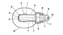
図1は本発明の実施の形態1に係るLED照明装置の構成を示す斜視図、図2は本実施の形態1におけるフレキシブル回路基板の平面図、図3は本実施の形態1に係るLED照明装置の断面図である。 FIG. 1 is a perspective view showing a configuration of an LED illumination device according to Embodiment 1 of the present invention, FIG. 2 is a plan view of a flexible circuit board according to Embodiment 1, and FIG. 3 is an LED illumination according to Embodiment 1. It is sectional drawing of an apparatus.
本実施の形態1のLED照明装置は、図2に示すように、展開したときに平面となる放射状のフレキシブル回路基板(Flexible Printed Circuit board、以下「FPC」という)1にLED2を複数実装し、各LED2を印刷配線で例えば直列接続し、端子3,4に引き出したものを使用する。FPC1としては、厚みが薄いエポキシ基板等を使用することができる。このFPC1を、本実施の形態では外形が八角柱形のアルミニウム製のコア5の表面に、熱伝導性接着剤、例えば放熱用シリコーン樹脂を用いて接着する。コア5の頭部は截頭八角錐となっており、その角錘部と角柱部にLED2が位置するようにしている。
As shown in FIG. 2, the LED lighting device according to the first embodiment has a plurality of
コア5の内部は空洞となっており、内部に電源回路基板6が収納されていて、商用電源電圧の交流100Vを、LED2を駆動するための電圧に変換するようにしている。電源回路基板6とFPC1の端子3,4とは、電線7により接続されている。コア5の基端部には絶縁体からなる取付ベース8が設けられており、この取付ベース8に、口金9が固着されている。取付ベース8としては、プラスチックやセラミックスが使用できるが、高熱伝導性プラスチックを使用すると、放熱効果が向上する。口金9と半田部10は内部において電線11により電源回路基板6に接続されている。
The
コア5には、複数のLED2を囲むキャップ12を被せたものとすることができる。キャップ12は透明または半透明なガラスまたはプラスチックで構成することができる。透明にした場合は、複数のLED2がそれぞれ点光源として見えるが、半透明ないし乳白色とすると、乱反射の作用により、キャップ12の全面が発光しているように見える。このキャップ12の内部は、白熱電球のように真空にする必要はないが、内部にゴミや湿気が入らないように乾燥した空気か不活性の窒素ガスなどを封入することが好ましい。
なお、FPC1がコア5の表面に露出しているままでもいいが、図4(b)に示すように、LED2の位置に対応する箇所に窓13aを設けたカバー13をコア5に被せて図4(a)のようにすると、FPC1が隠れてLED2のみが露出するので、意匠性が向上する。
The
The FPC 1 may remain exposed on the surface of the
以上の構成のLED照明装置を、白熱電球用のソケットに装着すると、口金9と半田部10に100Vの商用電源が供給される。その電源は電源回路基板6に供給され、そこでLED2を駆動するための電圧に変換されてFPC1に実装されたLED2に適正な電流が供給される。LED2のPN接合部で発生する熱は、FPC1、熱伝導性接着剤を介してコア5に伝達され放熱される。コア5の基端部は、図示していないが、フィンを形成することもできる。このように、厚みが薄いFPC1と表面積が大きなコア5により熱抵抗が小さくなり、LED2によって発生する熱は効率的に放熱される。これにより、高光度のLEDを複数用いても、LEDのジャンクション温度を最大ジャンクション温度よりも低い状態で使用でき、長寿命というLEDの特性を活かすことができる。
[実施の形態2]
When the LED lighting device having the above configuration is mounted on a socket for an incandescent lamp, a commercial power supply of 100 V is supplied to the base 9 and the solder portion 10. The power is supplied to the power supply circuit board 6, where it is converted into a voltage for driving the
[Embodiment 2]
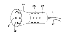
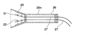
図5は本発明の実施の形態2に係るLED照明装置の構成を示す斜視図、図6はその正面図、図7はその断面図である。
FIG. 5 is a perspective view showing a configuration of an LED lighting device according to
本実施の形態2のLED照明装置は、展開したときに平面となる放射状のFPC21にLED22を複数実装し、各LED22を印刷配線で例えば直列接続し、端子23,24に引き出したものを使用する。FPC21としては、厚みが薄いエポキシ基板等を使用することができる。このFPC21を、アルミニウム製の反射器25の内面に、熱伝導性接着剤、例えば放熱用シリコーン樹脂を用いて接着する。反射器25の基部には筒部26が連設されており、放熱用の穴26aが設けられている。筒部26の内部には、FPC21の端子23,24に接続された電線27が引き出されており、外部の電源に接続される。なお、実施の形態1と同様に、筒部26の内部に電源回路基板を内蔵してもよい。
The LED lighting device according to the second embodiment uses a plurality of
以上の構成のLED照明装置に、電線27から電流を流すと、FPC21に実装されたLED22が点灯する。その光は反射器25内部で反射してある程度収束し、反射器25の前方より放射される。LED22のPN接合部で発生する熱は、FPC21、熱伝導性接着剤を介して反射器25に伝達され、反射器25の外面および反射器25に連設されている筒部26の外面より外気に放熱される。このように、厚みが薄いFPC1と表面が外気に接している反射器25および筒部26により熱抵抗が小さくなり、LED22によって発生する熱は効率的に放熱される。これにより、高光度のLEDを複数用いても、LEDのジャンクション温度を最大ジャンクション温度よりも低い状態で使用でき、長寿命というLEDの特性を活かすことができる。
When an electric current is passed from the
本発明は、LEDの熱抵抗が小さく、実装工程が簡単であり、また要求される指向性に応じてLEDを立体的に配置することのできる高光度のLED照明装置に利用することができる。 INDUSTRIAL APPLICABILITY The present invention can be used for a high-luminance LED lighting device in which the LED has a low thermal resistance, a mounting process is simple, and LEDs can be three-dimensionally arranged according to required directivity.
1 フレキシブル回路基板(FPC)
2 LED
3,4 端子
5 コア
6 電源回路基板
7 電線
8 取付ベース
9 口金
10 半田部
11 電線
12 キャップ
13 カバー
13a 窓
21 FPC
22 LED
23,24 端子
25 反射器
26 筒部
26a 穴
27 電線
1 Flexible circuit board (FPC)
2 LED
3,4
22 LED
23, 24
Claims (4)
Priority Applications (2)
| Application Number | Priority Date | Filing Date | Title |
|---|---|---|---|
| JP2005054642A JP2006244725A (en) | 2005-02-28 | 2005-02-28 | Led lighting system |
| US11/349,110 US20060193130A1 (en) | 2005-02-28 | 2006-02-08 | LED lighting system |
Applications Claiming Priority (1)
| Application Number | Priority Date | Filing Date | Title |
|---|---|---|---|
| JP2005054642A JP2006244725A (en) | 2005-02-28 | 2005-02-28 | Led lighting system |
Publications (1)
| Publication Number | Publication Date |
|---|---|
| JP2006244725A true JP2006244725A (en) | 2006-09-14 |
Family
ID=36931773
Family Applications (1)
| Application Number | Title | Priority Date | Filing Date |
|---|---|---|---|
| JP2005054642A Pending JP2006244725A (en) | 2005-02-28 | 2005-02-28 | Led lighting system |
Country Status (2)
| Country | Link |
|---|---|
| US (1) | US20060193130A1 (en) |
| JP (1) | JP2006244725A (en) |
Cited By (60)
| Publication number | Priority date | Publication date | Assignee | Title |
|---|---|---|---|---|
| JP2008091161A (en) * | 2006-09-29 | 2008-04-17 | Matsushita Electric Works Ltd | Led lighting system |
| JP2008103112A (en) * | 2006-10-17 | 2008-05-01 | Toshiba Lighting & Technology Corp | Led bulb and led luminaire |
| JP2008258080A (en) * | 2007-04-09 | 2008-10-23 | Hitachi Displays Ltd | Light source module, light source unit, liquid crystal display device, and lighting system |
| JP2009037820A (en) * | 2007-08-01 | 2009-02-19 | Toshiba Home Lighting Kk | Lighting system and luminaire |
| WO2009051128A1 (en) * | 2007-10-16 | 2009-04-23 | Toshiba Lighting & Technology Corporation | Light emitting element lamp and lighting equipment |
| JP2009135026A (en) * | 2007-11-30 | 2009-06-18 | Toshiba Lighting & Technology Corp | Led luminaire |
| JP2009184772A (en) * | 2008-02-05 | 2009-08-20 | Hitachi Building Systems Co Ltd | Lighting system of passenger conveyer |
| JP2009283449A (en) * | 2008-03-27 | 2009-12-03 | Cree Inc | Uniform intensity led lighting system |
| WO2009157704A2 (en) * | 2008-06-25 | 2009-12-30 | 주식회사 에이엠오 | Led package and manufacturing method for same |
| KR200448185Y1 (en) * | 2009-09-18 | 2010-03-24 | 박창수 | Illumination light and connection support device |
| JP2010073337A (en) * | 2008-09-16 | 2010-04-02 | Toshiba Lighting & Technology Corp | Light-bulb type lamp |
| WO2010053147A1 (en) * | 2008-11-06 | 2010-05-14 | ローム株式会社 | Led lamp |
| JP2010135309A (en) * | 2008-11-06 | 2010-06-17 | Rohm Co Ltd | Led lamp |
| JP2010541152A (en) * | 2007-09-27 | 2010-12-24 | コーニンクレッカ フィリップス エレクトロニクス エヌ ヴィ | Light emitting device and method for cooling light emitting device |
| JP2011040364A (en) * | 2009-07-16 | 2011-02-24 | Pearl Lighting Co Ltd | Led lamp |
| JP2011510490A (en) * | 2008-01-10 | 2011-03-31 | ゲーケン・グループ・コーポレーション | LED lamp replacement of low power incandescent lamp |
| JP2011070971A (en) * | 2009-09-25 | 2011-04-07 | Toshiba Lighting & Technology Corp | Self-ballasted lamp and lighting fixture |
| JP2011086615A (en) * | 2009-10-16 | 2011-04-28 | Foxsemicon Integrated Technology Inc | Illumination device |
| JP2011113746A (en) * | 2009-11-25 | 2011-06-09 | Yu-Lin Chu | Led light emitting structure |
| JP2011523180A (en) * | 2008-06-04 | 2011-08-04 | フォーエバー・バルブ・リミテッド・ライアビリティ・カンパニー | LED bulb device |
| JP2011150910A (en) * | 2010-01-22 | 2011-08-04 | Lead Co Ltd | Globe type led illumination device |
| WO2011105030A1 (en) * | 2010-02-23 | 2011-09-01 | 東芝ライテック株式会社 | Lamp with base, and illumination device |
| JP2011524615A (en) * | 2008-06-19 | 2011-09-01 | パナソニック株式会社 | LED lamp with combined heat dissipation structure |
| JP2011175916A (en) * | 2010-02-25 | 2011-09-08 | Olympia Shomei Co Ltd | Luminaire |
| JP2011222411A (en) * | 2010-04-13 | 2011-11-04 | Tss Kk | Lighting device and light source substrate to be used for the same |
| JP2011243512A (en) * | 2010-05-20 | 2011-12-01 | Birumen Kagoshima:Kk | Led lighting tool |
| JP2011253782A (en) * | 2010-06-04 | 2011-12-15 | Panasonic Corp | Led lamp |
| JP2012033485A (en) * | 2010-07-28 | 2012-02-16 | Man-Tsu Chang | Bulb type lighting system |
| JP2012094304A (en) * | 2010-10-25 | 2012-05-17 | Panasonic Corp | Light-emitting device and lighting fixture equipped with the same |
| JP2012099375A (en) * | 2010-11-04 | 2012-05-24 | Stanley Electric Co Ltd | Bulb type led lamp |
| JP2012142277A (en) * | 2010-12-31 | 2012-07-26 | Novalite Optronics Corp | Light emitting diode lamp and method for fabricating the same |
| JP2012181953A (en) * | 2011-02-28 | 2012-09-20 | Toshiba Corp | Lighting system |
| US8324789B2 (en) | 2009-09-25 | 2012-12-04 | Toshiba Lighting & Technology Corporation | Self-ballasted lamp and lighting equipment |
| JP2012243643A (en) * | 2011-05-20 | 2012-12-10 | Panasonic Corp | Bulb type lamp and lighting device |
| US8354783B2 (en) | 2009-09-24 | 2013-01-15 | Toshiba Lighting & Technology Corporation | Light-emitting device.having a frame member surrounding light-emitting elements and illumination device utilizing light-emitting device |
| US8376562B2 (en) | 2009-09-25 | 2013-02-19 | Toshiba Lighting & Technology Corporation | Light-emitting module, self-ballasted lamp and lighting equipment |
| US8382325B2 (en) | 2009-06-30 | 2013-02-26 | Toshiba Lighting & Technology Corporation | Lamp and lighting equipment using the same |
| US8395304B2 (en) | 2009-09-25 | 2013-03-12 | Toshiba Lighting & Technology Corporation | Lamp and lighting equipment with thermally conductive substrate and body |
| US8415889B2 (en) | 2009-07-29 | 2013-04-09 | Toshiba Lighting & Technology Corporation | LED lighting equipment |
| WO2013069446A1 (en) * | 2011-11-09 | 2013-05-16 | 岩崎電気株式会社 | Lamp |
| JP2013527575A (en) * | 2010-05-27 | 2013-06-27 | シ,ジエ | Heat dissipation device for LED bulb and LED bulb with high heat dissipation |
| JP2013138034A (en) * | 2013-04-08 | 2013-07-11 | Toshiba Lighting & Technology Corp | Bulb type lamp |
| US8500316B2 (en) | 2010-02-26 | 2013-08-06 | Toshiba Lighting & Technology Corporation | Self-ballasted lamp and lighting equipment |
| KR20130124819A (en) * | 2012-05-07 | 2013-11-15 | 엘지이노텍 주식회사 | Lighting device |
| JP2013235823A (en) * | 2012-05-07 | 2013-11-21 | Lg Innotek Co Ltd | Lighting device |
| JP2013239743A (en) * | 2009-02-23 | 2013-11-28 | Shinko Electric Ind Co Ltd | Wiring board and manufacturing method of the same |
| KR20130131777A (en) * | 2012-05-24 | 2013-12-04 | 엘지이노텍 주식회사 | Lighting device |
| JP2014003032A (en) * | 2013-08-30 | 2014-01-09 | Toshiba Lighting & Technology Corp | Electric bulb type lamp and luminaire |
| KR101367360B1 (en) * | 2012-04-10 | 2014-02-26 | 송인실 | Flexible heat dissipating substrate for led lighting module and led lighting module with the same |
| US8678618B2 (en) | 2009-09-25 | 2014-03-25 | Toshiba Lighting & Technology Corporation | Self-ballasted lamp having a light-transmissive member in contact with light emitting elements and lighting equipment incorporating the same |
| JP2014508389A (en) * | 2011-03-17 | 2014-04-03 | 北京優格莱照明科技有限公司 | Liquid-cooled LED lighting |
| WO2014049916A1 (en) * | 2012-09-26 | 2014-04-03 | パナソニック株式会社 | Lamp |
| JP5564696B1 (en) * | 2013-05-02 | 2014-07-30 | シーシーエス株式会社 | Lighting device |
| US8858041B2 (en) | 2005-04-08 | 2014-10-14 | Toshiba Lighting & Technology Corporation | Lamp having outer shell to radiate heat of light source |
| JP2015511370A (en) * | 2012-09-24 | 2015-04-16 | 蘇州晶品光電科技有限公司Suzhou Jingpin Optoelectronic Co.,Ltd | Almost omnidirectional LED lamp |
| JP2015521357A (en) * | 2012-06-04 | 2015-07-27 | コーニンクレッカ フィリップス エヌ ヴェ | Lamp with flexible printed circuit board |
| JP2015534216A (en) * | 2012-09-18 | 2015-11-26 | コーニンクレッカ フィリップス エヌ ヴェKoninklijke Philips N.V. | Lamp with heat sink |
| JP2016092306A (en) * | 2014-11-07 | 2016-05-23 | 住友電工プリントサーキット株式会社 | Led module and led lighting device |
| JP2016201206A (en) * | 2015-04-08 | 2016-12-01 | 三菱電機株式会社 | lamp |
| US9719671B2 (en) | 2011-09-02 | 2017-08-01 | Lg Innotek Co., Ltd. | Lighting device |
Families Citing this family (117)
| Publication number | Priority date | Publication date | Assignee | Title |
|---|---|---|---|---|
| US10340424B2 (en) | 2002-08-30 | 2019-07-02 | GE Lighting Solutions, LLC | Light emitting diode component |
| US20070159828A1 (en) * | 2006-01-09 | 2007-07-12 | Ceramate Technical Co., Ltd. | Vertical LED lamp with a 360-degree radiation and a high cooling efficiency |
| EP2021683A4 (en) * | 2006-05-02 | 2010-10-27 | Superbulbs Inc | Heat removal design for led bulbs |
| WO2007130358A2 (en) * | 2006-05-02 | 2007-11-15 | Superbulbs, Inc. | Plastic led bulb |
| EP2013919A2 (en) | 2006-05-02 | 2009-01-14 | Superbulbs, Inc. | Method of light dispersion and preferential scattering of certain wavelengths of light for light-emitting diodes and bulbs constructed therefrom |
| DE102007009229B4 (en) * | 2007-02-26 | 2015-01-08 | Zumtobel Lighting Gmbh | Light source for simulating a point light source, and light with such a light source |
| WO2008154172A1 (en) * | 2007-06-08 | 2008-12-18 | Superbulbs, Inc. | Apparatus for cooling leds in a bulb |
| CN100526707C (en) * | 2007-07-11 | 2009-08-12 | 宁波安迪光电科技有限公司 | Highpower LED street lamp |
| DE102007038216A1 (en) * | 2007-08-13 | 2009-02-19 | Johann Daunderer | LED bulb in the form of a light bulb |
| US8439528B2 (en) | 2007-10-03 | 2013-05-14 | Switch Bulb Company, Inc. | Glass LED light bulbs |
| CN101896766B (en) | 2007-10-24 | 2014-04-23 | 开关电灯公司 | Diffuser for LED light sources |
| KR100906087B1 (en) * | 2007-10-26 | 2009-07-06 | 화우테크놀러지 주식회사 | A led lighting fitting |
| US7726836B2 (en) * | 2007-11-23 | 2010-06-01 | Taiming Chen | Light bulb with light emitting elements for use in conventional incandescent light bulb sockets |
| JP5353216B2 (en) * | 2008-01-07 | 2013-11-27 | 東芝ライテック株式会社 | LED bulb and lighting fixture |
| ITNA20080011A1 (en) * | 2008-02-15 | 2009-08-16 | Self Sime Italia Ricerca & Sviluppo Srl | LED POWER LAMP FOR LIGHTS LANTERNS. |
| WO2009122453A1 (en) * | 2008-04-02 | 2009-10-08 | Wissen Lux S.P.A. | Led lighting apparatus |
| EP2256402A4 (en) * | 2008-06-27 | 2012-08-15 | Toshiba Lighting & Technology | Light-emitting element lamp and lighting fixture |
| KR100965558B1 (en) | 2008-07-22 | 2010-06-23 | (주)아이엠 | LED Bulb |
| AT524690B1 (en) * | 2008-07-24 | 2022-08-15 | Tridonic Gmbh & Co Kg | LAMPS WITH LED |
| DE102008036487B4 (en) * | 2008-08-05 | 2016-12-15 | Osram Opto Semiconductors Gmbh | Bulbs and use of a bulb |
| PL2318751T3 (en) * | 2008-09-05 | 2012-12-31 | Braun Andre | Gas lighting means |
| US7902761B2 (en) | 2008-10-03 | 2011-03-08 | Next Gen Illumination, Inc | Dimmable LED lamp |
| WO2010040645A2 (en) * | 2008-10-08 | 2010-04-15 | Osram Gesellschaft mit beschränkter Haftung | Circuit carrier |
| CN201293279Y (en) * | 2008-10-16 | 2009-08-19 | 郑榕彬 | LED illumination lamp |
| CN102301181A (en) * | 2009-02-17 | 2011-12-28 | 西尔欧集团 | LED light bulbs for space lighting |
| JP5333758B2 (en) * | 2009-02-27 | 2013-11-06 | 東芝ライテック株式会社 | Lighting device and lighting fixture |
| ITCN20090004A1 (en) * | 2009-03-04 | 2010-09-05 | Paolo Squassino | LED LAMP |
| US20100327726A1 (en) * | 2009-06-27 | 2010-12-30 | Harris Technology, Llc | LED bulb |
| CN101963293B (en) * | 2009-07-21 | 2014-04-30 | 富准精密工业(深圳)有限公司 | Light-emitting diode lamp |
| FR2949842B1 (en) * | 2009-09-09 | 2011-12-16 | Peugeot Citroen Automobiles Sa | FIRE FOR MOTOR VEHICLE |
| JP5601512B2 (en) * | 2009-09-14 | 2014-10-08 | 東芝ライテック株式会社 | Light emitting device and lighting device |
| US20130223082A1 (en) * | 2009-09-27 | 2013-08-29 | Dongguan Light Source Opto Tech Co., Ltd. | Led device for three-dimensional illumination |
| US20110073886A1 (en) * | 2009-09-28 | 2011-03-31 | Han-Ming Lee | LED multi-side light source bracket |
| US8593040B2 (en) | 2009-10-02 | 2013-11-26 | Ge Lighting Solutions Llc | LED lamp with surface area enhancing fins |
| CN102042518A (en) * | 2009-10-16 | 2011-05-04 | 富士迈半导体精密工业(上海)有限公司 | Lighting device |
| US9243758B2 (en) | 2009-10-20 | 2016-01-26 | Cree, Inc. | Compact heat sinks and solid state lamp incorporating same |
| US9217542B2 (en) | 2009-10-20 | 2015-12-22 | Cree, Inc. | Heat sinks and lamp incorporating same |
| EP2314913A1 (en) | 2009-10-21 | 2011-04-27 | Tyco Electronics Nederland B.V. | Light emitting unit carrier and light source comprising such a carrier |
| CN102087013A (en) * | 2009-12-04 | 2011-06-08 | 富准精密工业(深圳)有限公司 | Light-emitting diode (LED) lamp |
| CN201568915U (en) * | 2009-12-14 | 2010-09-01 | 东莞市美能电子有限公司 | Luminous device and illumination device thereof |
| EP2339223B1 (en) * | 2009-12-23 | 2014-05-14 | Novabase Digital TV Technologies GmbH | LED Bulb |
| US8536807B2 (en) * | 2010-01-04 | 2013-09-17 | Dongguan Hexi Optical Electric Technology Co., Ltd. | LED bulb |
| US8541933B2 (en) * | 2010-01-12 | 2013-09-24 | GE Lighting Solutions, LLC | Transparent thermally conductive polymer composites for light source thermal management |
| US8729781B2 (en) * | 2010-03-03 | 2014-05-20 | Koninklijke Philips N.V. | Electric lamp having reflector for transferring heat from light source |
| AU2011253167A1 (en) * | 2010-05-11 | 2013-01-10 | Goeken Group Corporation | High intensity LED replacement of incandescent lamps |
| CN101825241B (en) * | 2010-05-14 | 2011-08-17 | 江苏史福特光电科技有限公司 | LED bulb |
| DE102010029270A1 (en) * | 2010-05-25 | 2011-12-01 | Osram Gesellschaft mit beschränkter Haftung | Semiconductor lighting device, method for producing a carrier substrate and method for applying a carrier substrate to a heat sink |
| US8596821B2 (en) | 2010-06-08 | 2013-12-03 | Cree, Inc. | LED light bulbs |
| CN201696936U (en) * | 2010-06-13 | 2011-01-05 | 沈锦祥 | LED tower-shaped luminescent module |
| CN101852357A (en) * | 2010-06-21 | 2010-10-06 | 中山市汉仁电子有限公司 | LED light-emitting device |
| DE102010031008A1 (en) * | 2010-07-06 | 2012-01-12 | Osram Gesellschaft mit beschränkter Haftung | LED light |
| KR101153281B1 (en) | 2010-08-02 | 2012-06-12 | 홍삼표 | Light emitting diode bulb |
| CN201748230U (en) * | 2010-08-26 | 2011-02-16 | 吴大明 | Bulb taking LED as light source |
| TWM412319U (en) * | 2010-11-01 | 2011-09-21 | Parlux Optoelectronics Corp | LED illumination device |
| US8192051B2 (en) | 2010-11-01 | 2012-06-05 | Quarkstar Llc | Bidirectional LED light sheet |
| US20120169251A1 (en) * | 2010-12-31 | 2012-07-05 | Novalite Optronics Corp. | Light emitting diode lamp and method for fabricating the same |
| JP5671356B2 (en) * | 2011-01-26 | 2015-02-18 | ローム株式会社 | LED bulb |
| US8410726B2 (en) | 2011-02-22 | 2013-04-02 | Quarkstar Llc | Solid state lamp using modular light emitting elements |
| US8314566B2 (en) | 2011-02-22 | 2012-11-20 | Quarkstar Llc | Solid state lamp using light emitting strips |
| CN102650385A (en) * | 2011-02-25 | 2012-08-29 | 瑞莹光电股份有限公司 | Light emitting diode lamp and manufacturing method thereof |
| CN102650380A (en) * | 2011-02-25 | 2012-08-29 | 瑞莹光电股份有限公司 | Light emitting diode lamp and manufacturing method thereof |
| JP5759781B2 (en) * | 2011-03-31 | 2015-08-05 | ローム株式会社 | LED bulb |
| US10030863B2 (en) * | 2011-04-19 | 2018-07-24 | Cree, Inc. | Heat sink structures, lighting elements and lamps incorporating same, and methods of making same |
| JP5701668B2 (en) * | 2011-04-22 | 2015-04-15 | 矢崎総業株式会社 | LED lighting unit |
| WO2013000346A1 (en) * | 2011-06-29 | 2013-01-03 | 优杰精密机械(苏州)有限公司 | Led light strip/board |
| CN102853308A (en) * | 2011-06-29 | 2013-01-02 | 优杰精密机械(苏州)有限公司 | LED (light-emitting diode) light bar |
| US8591069B2 (en) | 2011-09-21 | 2013-11-26 | Switch Bulb Company, Inc. | LED light bulb with controlled color distribution using quantum dots |
| CN103032696A (en) * | 2011-09-30 | 2013-04-10 | Tss株式会社 | Lighting device and light source substrate used in lighting device |
| CN104254904A (en) * | 2011-10-31 | 2014-12-31 | 登森·西尔 | Led light source |
| CN104024723B (en) * | 2011-11-23 | 2016-08-24 | 3M创新有限公司 | There is the flexible luminous semiconductor device of three-dimensional structure |
| KR20130084884A (en) * | 2012-01-18 | 2013-07-26 | 삼성전자주식회사 | Illuminating device |
| CN102635793A (en) * | 2012-03-07 | 2012-08-15 | 深圳和而泰照明科技有限公司 | Luminous structure and LED (light emitting diode) lamp with same |
| CN103322429A (en) * | 2012-03-19 | 2013-09-25 | 台达电子工业股份有限公司 | Multidirectional bulb type lamp |
| US8757839B2 (en) * | 2012-04-13 | 2014-06-24 | Cree, Inc. | Gas cooled LED lamp |
| US9410687B2 (en) | 2012-04-13 | 2016-08-09 | Cree, Inc. | LED lamp with filament style LED assembly |
| US9500355B2 (en) | 2012-05-04 | 2016-11-22 | GE Lighting Solutions, LLC | Lamp with light emitting elements surrounding active cooling device |
| TW201411030A (en) * | 2012-09-12 | 2014-03-16 | Apm Communication Inc | Light source module and bulb lamp |
| DE102012216911A1 (en) * | 2012-09-20 | 2014-03-20 | Osram Gmbh | Method for manufacturing light assembly for lamp, involves bending circuit path of circuit path structure, so as to divide circuit path structure into tilted patches |
| CN103016987A (en) * | 2012-12-18 | 2013-04-03 | 居学良 | LED (light-emitting diode) bulb |
| CN103032739A (en) * | 2012-12-26 | 2013-04-10 | 惠州市东扬科技有限公司 | Patch LED (Light-Emitting Diode) lamp capable of emitting light on multiple faces |
| CN103090234A (en) * | 2013-01-23 | 2013-05-08 | 中山市美耐特光电有限公司 | Light-emitting diode (LED) energy-saving lamp |
| US9310063B1 (en) * | 2013-03-12 | 2016-04-12 | Mark A. Lauer | Lighting device with fins that conduct heat and reflect light outward from light sources |
| JP6105811B2 (en) * | 2013-05-14 | 2017-03-29 | フィリップス ライティング ホールディング ビー ヴィ | LIGHTING DEVICE AND METHOD FOR MANUFACTURING LIGHTING DEVICE |
| US20140375202A1 (en) * | 2013-06-25 | 2014-12-25 | Uniled Lighting Tw., Inc. | Led bulb |
| WO2014209055A1 (en) * | 2013-06-28 | 2014-12-31 | 서울반도체 주식회사 | Lighting apparatus |
| KR102325502B1 (en) * | 2013-06-28 | 2021-11-15 | 서울반도체 주식회사 | Lightting device |
| US20150003058A1 (en) * | 2013-07-01 | 2015-01-01 | Biao Zhang | Led light bulb |
| CN103423646A (en) * | 2013-08-26 | 2013-12-04 | 立达信绿色照明股份有限公司 | Integrated LED (Light Emitting Diode) bulb |
| CN203517389U (en) * | 2013-09-23 | 2014-04-02 | 马士科技有限公司 | LED bulb |
| JP6301097B2 (en) * | 2013-10-01 | 2018-03-28 | シチズン電子株式会社 | Semiconductor light emitting device |
| CN103742874A (en) * | 2013-12-31 | 2014-04-23 | 河南云华灿光电科技有限公司 | Aluminum substrate mechanism and LED (Light Emitting Diode) bulb lamp comprising same |
| US9555610B2 (en) * | 2014-03-10 | 2017-01-31 | Forever Bulb, Llc | LED light bulb with internal flexible heatsink and circuit |
| CN104035233B (en) * | 2014-06-13 | 2017-02-01 | 京东方科技集团股份有限公司 | Display screen frame eliminating device and display equipment |
| US9765956B2 (en) | 2014-08-04 | 2017-09-19 | Spring City Electrical Manufacturing Company | LED luminaire light fixture for a lamppost |
| CN104456182B (en) * | 2014-10-09 | 2016-08-24 | 邓放明 | A kind of can the manufacture method of LED aluminum base plate light source of bending |
| CN204141334U (en) * | 2014-10-10 | 2015-02-04 | 佛山燊业光电有限公司 | A kind of comprehensive LEDbulb lamp without blackening |
| US20160208986A1 (en) * | 2015-01-15 | 2016-07-21 | Ed Davis | Omniled light bulb system methods and apparatus |
| SG10201504177QA (en) * | 2015-05-27 | 2016-12-29 | 3M Innovative Properties Co | Lighting device, element thereof and a vehicle headlamp |
| EP3394509A1 (en) * | 2015-12-21 | 2018-10-31 | SABIC Global Technologies B.V. | Thermal conductive flexible pcb and all plastic heat sink for led bulb retrofit |
| CN105805579A (en) * | 2016-01-18 | 2016-07-27 | 漳州立达信光电子科技有限公司 | Large-angle light-emitting LED filament lamp |
| CN106195679A (en) * | 2016-06-30 | 2016-12-07 | 浙江生辉照明有限公司 | A kind of LED |
| WO2018019655A1 (en) * | 2016-07-26 | 2018-02-01 | Philips Lighting Holding B.V. | A light emitting device |
| CN206130567U (en) * | 2016-09-30 | 2017-04-26 | 朱永明 | LED light source substrate |
| CN206093556U (en) * | 2016-09-30 | 2017-04-12 | 朱永明 | LED (Light emitting diode) light source device |
| US11293632B2 (en) * | 2017-12-29 | 2022-04-05 | Shenzhen Fluence Technology Plc | Lamp and light source substrate thereof |
| US10943945B2 (en) | 2018-05-04 | 2021-03-09 | Lumileds Llc | Light fixture with dynamically controllable light distribution |
| US10821890B2 (en) | 2018-05-04 | 2020-11-03 | Lumileds Llc | Light engines with dynamically controllable light distribution |
| US10622405B2 (en) * | 2018-05-04 | 2020-04-14 | Lumileds Llc | Light fixture with dynamically controllable light distribution |
| US10750588B2 (en) | 2018-05-04 | 2020-08-18 | Lumileds Llc | Light fixture with dynamically controllable light distribution |
| US10859757B2 (en) * | 2018-05-04 | 2020-12-08 | Lumileds Llc | Light fixture with light guide and radially emitting LEDs |
| US10785847B2 (en) | 2018-05-04 | 2020-09-22 | Lumileds Llc | Light engines with dynamically controllable light distribution |
| US10872923B2 (en) | 2018-05-04 | 2020-12-22 | Lumileds Llc | Light engines with dynamically controllable light distribution |
| US10845529B2 (en) | 2018-05-04 | 2020-11-24 | Lumileds Llc | Light engines with dynamically controllable light distribution |
| CN211344826U (en) * | 2019-09-17 | 2020-08-25 | 欧普照明股份有限公司 | Lamp body and bulb lamp |
| US11774046B2 (en) | 2020-03-12 | 2023-10-03 | Zhejiang Yankon Mega Lighting Co., Ltd. | LED light source assembly and high-power lamp using the same |
| US11592166B2 (en) | 2020-05-12 | 2023-02-28 | Feit Electric Company, Inc. | Light emitting device having improved illumination and manufacturing flexibility |
| US11876042B2 (en) | 2020-08-03 | 2024-01-16 | Feit Electric Company, Inc. | Omnidirectional flexible light emitting device |
Family Cites Families (3)
| Publication number | Priority date | Publication date | Assignee | Title |
|---|---|---|---|---|
| JP4076329B2 (en) * | 2001-08-13 | 2008-04-16 | エイテックス株式会社 | LED bulb |
| TW533750B (en) * | 2001-11-11 | 2003-05-21 | Solidlite Corp | LED lamp |
| US7086767B2 (en) * | 2004-05-12 | 2006-08-08 | Osram Sylvania Inc. | Thermally efficient LED bulb |
-
2005
- 2005-02-28 JP JP2005054642A patent/JP2006244725A/en active Pending
-
2006
- 2006-02-08 US US11/349,110 patent/US20060193130A1/en not_active Abandoned
Cited By (90)
| Publication number | Priority date | Publication date | Assignee | Title |
|---|---|---|---|---|
| US9103541B2 (en) | 2005-04-08 | 2015-08-11 | Toshiba Lighting & Technology Corporation | Lamp having outer shell to radiate heat of light source |
| US8992041B2 (en) | 2005-04-08 | 2015-03-31 | Toshiba Lighting & Technology Corporation | Lamp having outer shell to radiate heat of light source |
| US9249967B2 (en) | 2005-04-08 | 2016-02-02 | Toshiba Lighting & Technology Corporation | Lamp having outer shell to radiate heat of light source |
| US9234657B2 (en) | 2005-04-08 | 2016-01-12 | Toshiba Lighting & Technology Corporation | Lamp having outer shell to radiate heat of light source |
| US8979315B2 (en) | 2005-04-08 | 2015-03-17 | Toshiba Lighting & Technology Corporation | Lamp having outer shell to radiate heat of light source |
| US9772098B2 (en) | 2005-04-08 | 2017-09-26 | Toshiba Lighting & Technology Corporation | Lamp having outer shell to radiate heat of light source |
| US9080759B2 (en) | 2005-04-08 | 2015-07-14 | Toshiba Lighting & Technology Corporation | Lamp having outer shell to radiate heat of light source |
| US8858041B2 (en) | 2005-04-08 | 2014-10-14 | Toshiba Lighting & Technology Corporation | Lamp having outer shell to radiate heat of light source |
| JP2008091161A (en) * | 2006-09-29 | 2008-04-17 | Matsushita Electric Works Ltd | Led lighting system |
| JP2008103112A (en) * | 2006-10-17 | 2008-05-01 | Toshiba Lighting & Technology Corp | Led bulb and led luminaire |
| JP2008258080A (en) * | 2007-04-09 | 2008-10-23 | Hitachi Displays Ltd | Light source module, light source unit, liquid crystal display device, and lighting system |
| JP2009037820A (en) * | 2007-08-01 | 2009-02-19 | Toshiba Home Lighting Kk | Lighting system and luminaire |
| JP2010541152A (en) * | 2007-09-27 | 2010-12-24 | コーニンクレッカ フィリップス エレクトロニクス エヌ ヴィ | Light emitting device and method for cooling light emitting device |
| WO2009051128A1 (en) * | 2007-10-16 | 2009-04-23 | Toshiba Lighting & Technology Corporation | Light emitting element lamp and lighting equipment |
| US9018828B2 (en) | 2007-10-16 | 2015-04-28 | Toshiba Lighting & Technology Corporation | Light emitting element lamp and lighting equipment |
| JP2009135026A (en) * | 2007-11-30 | 2009-06-18 | Toshiba Lighting & Technology Corp | Led luminaire |
| US11703191B2 (en) | 2008-01-10 | 2023-07-18 | Feit Electric Company, Inc. | LED lamp |
| US10753547B2 (en) | 2008-01-10 | 2020-08-25 | Feit Electric Company, Inc. | LED lamp |
| JP2011510490A (en) * | 2008-01-10 | 2011-03-31 | ゲーケン・グループ・コーポレーション | LED lamp replacement of low power incandescent lamp |
| JP2014167940A (en) * | 2008-01-10 | 2014-09-11 | Geeken Group Corp | Led lamp replacement of low power incandescent lamp |
| US11262028B2 (en) | 2008-01-10 | 2022-03-01 | Feit Electric Company, Inc. | LED lamp |
| US10845009B2 (en) | 2008-01-10 | 2020-11-24 | Feit Electric Company, Inc. | LED lamp |
| JP2009184772A (en) * | 2008-02-05 | 2009-08-20 | Hitachi Building Systems Co Ltd | Lighting system of passenger conveyer |
| JP2009283449A (en) * | 2008-03-27 | 2009-12-03 | Cree Inc | Uniform intensity led lighting system |
| JP2011523180A (en) * | 2008-06-04 | 2011-08-04 | フォーエバー・バルブ・リミテッド・ライアビリティ・カンパニー | LED bulb device |
| JP2011524615A (en) * | 2008-06-19 | 2011-09-01 | パナソニック株式会社 | LED lamp with combined heat dissipation structure |
| WO2009157704A2 (en) * | 2008-06-25 | 2009-12-30 | 주식회사 에이엠오 | Led package and manufacturing method for same |
| WO2009157704A3 (en) * | 2008-06-25 | 2010-03-25 | 주식회사 아모럭스 | Led package and manufacturing method for same |
| JP2010073337A (en) * | 2008-09-16 | 2010-04-02 | Toshiba Lighting & Technology Corp | Light-bulb type lamp |
| WO2010053147A1 (en) * | 2008-11-06 | 2010-05-14 | ローム株式会社 | Led lamp |
| JP2010135309A (en) * | 2008-11-06 | 2010-06-17 | Rohm Co Ltd | Led lamp |
| JP2010135308A (en) * | 2008-11-06 | 2010-06-17 | Rohm Co Ltd | Led lamp |
| JP4642129B2 (en) * | 2008-11-06 | 2011-03-02 | ローム株式会社 | LED lamp |
| US8698290B2 (en) | 2008-11-06 | 2014-04-15 | Rohm Co., Ltd. | LED lamp |
| JP2011054577A (en) * | 2008-11-06 | 2011-03-17 | Rohm Co Ltd | Led lamp |
| JP2013239743A (en) * | 2009-02-23 | 2013-11-28 | Shinko Electric Ind Co Ltd | Wiring board and manufacturing method of the same |
| US8382325B2 (en) | 2009-06-30 | 2013-02-26 | Toshiba Lighting & Technology Corporation | Lamp and lighting equipment using the same |
| JP2011040364A (en) * | 2009-07-16 | 2011-02-24 | Pearl Lighting Co Ltd | Led lamp |
| US8415889B2 (en) | 2009-07-29 | 2013-04-09 | Toshiba Lighting & Technology Corporation | LED lighting equipment |
| KR200448185Y1 (en) * | 2009-09-18 | 2010-03-24 | 박창수 | Illumination light and connection support device |
| US8354783B2 (en) | 2009-09-24 | 2013-01-15 | Toshiba Lighting & Technology Corporation | Light-emitting device.having a frame member surrounding light-emitting elements and illumination device utilizing light-emitting device |
| US8395304B2 (en) | 2009-09-25 | 2013-03-12 | Toshiba Lighting & Technology Corporation | Lamp and lighting equipment with thermally conductive substrate and body |
| US8376562B2 (en) | 2009-09-25 | 2013-02-19 | Toshiba Lighting & Technology Corporation | Light-emitting module, self-ballasted lamp and lighting equipment |
| JP2011070971A (en) * | 2009-09-25 | 2011-04-07 | Toshiba Lighting & Technology Corp | Self-ballasted lamp and lighting fixture |
| US8324789B2 (en) | 2009-09-25 | 2012-12-04 | Toshiba Lighting & Technology Corporation | Self-ballasted lamp and lighting equipment |
| US8998457B2 (en) | 2009-09-25 | 2015-04-07 | Toshiba Lighting & Technology Corporation | Self-ballasted lamp and lighting equipment having a support portion in contact with an inner circumference of a base body |
| US8678618B2 (en) | 2009-09-25 | 2014-03-25 | Toshiba Lighting & Technology Corporation | Self-ballasted lamp having a light-transmissive member in contact with light emitting elements and lighting equipment incorporating the same |
| JP2011086615A (en) * | 2009-10-16 | 2011-04-28 | Foxsemicon Integrated Technology Inc | Illumination device |
| JP2011113746A (en) * | 2009-11-25 | 2011-06-09 | Yu-Lin Chu | Led light emitting structure |
| JP2011150910A (en) * | 2010-01-22 | 2011-08-04 | Lead Co Ltd | Globe type led illumination device |
| JP2011175771A (en) * | 2010-02-23 | 2011-09-08 | Toshiba Lighting & Technology Corp | Metal base lamp and luminaire |
| WO2011105030A1 (en) * | 2010-02-23 | 2011-09-01 | 東芝ライテック株式会社 | Lamp with base, and illumination device |
| CN102575819A (en) * | 2010-02-23 | 2012-07-11 | 东芝照明技术株式会社 | Lamp with base, and illumination device |
| JP2011175916A (en) * | 2010-02-25 | 2011-09-08 | Olympia Shomei Co Ltd | Luminaire |
| US8500316B2 (en) | 2010-02-26 | 2013-08-06 | Toshiba Lighting & Technology Corporation | Self-ballasted lamp and lighting equipment |
| JP2011222411A (en) * | 2010-04-13 | 2011-11-04 | Tss Kk | Lighting device and light source substrate to be used for the same |
| JP2011243512A (en) * | 2010-05-20 | 2011-12-01 | Birumen Kagoshima:Kk | Led lighting tool |
| JP2013527575A (en) * | 2010-05-27 | 2013-06-27 | シ,ジエ | Heat dissipation device for LED bulb and LED bulb with high heat dissipation |
| JP2011253782A (en) * | 2010-06-04 | 2011-12-15 | Panasonic Corp | Led lamp |
| JP2012033485A (en) * | 2010-07-28 | 2012-02-16 | Man-Tsu Chang | Bulb type lighting system |
| JP2012094304A (en) * | 2010-10-25 | 2012-05-17 | Panasonic Corp | Light-emitting device and lighting fixture equipped with the same |
| JP2012099375A (en) * | 2010-11-04 | 2012-05-24 | Stanley Electric Co Ltd | Bulb type led lamp |
| JP2012142277A (en) * | 2010-12-31 | 2012-07-26 | Novalite Optronics Corp | Light emitting diode lamp and method for fabricating the same |
| JP2012181953A (en) * | 2011-02-28 | 2012-09-20 | Toshiba Corp | Lighting system |
| JP2014508389A (en) * | 2011-03-17 | 2014-04-03 | 北京優格莱照明科技有限公司 | Liquid-cooled LED lighting |
| JP2012243643A (en) * | 2011-05-20 | 2012-12-10 | Panasonic Corp | Bulb type lamp and lighting device |
| US9970644B2 (en) | 2011-09-02 | 2018-05-15 | Lg Innotek Co., Ltd. | Lighting device |
| US10260724B2 (en) | 2011-09-02 | 2019-04-16 | Lg Innotek Co., Ltd. | Lighting device |
| US9719671B2 (en) | 2011-09-02 | 2017-08-01 | Lg Innotek Co., Ltd. | Lighting device |
| US9239151B2 (en) | 2011-11-09 | 2016-01-19 | Iwasaki Electric Co., Ltd. | Lamp |
| WO2013069446A1 (en) * | 2011-11-09 | 2013-05-16 | 岩崎電気株式会社 | Lamp |
| US9097391B2 (en) | 2011-11-09 | 2015-08-04 | Iwasaki Electric Co., Ltd. | Lamp |
| KR101367360B1 (en) * | 2012-04-10 | 2014-02-26 | 송인실 | Flexible heat dissipating substrate for led lighting module and led lighting module with the same |
| KR101977649B1 (en) * | 2012-05-07 | 2019-05-13 | 엘지이노텍 주식회사 | Lighting device |
| KR20130124819A (en) * | 2012-05-07 | 2013-11-15 | 엘지이노텍 주식회사 | Lighting device |
| USRE47425E1 (en) | 2012-05-07 | 2019-06-04 | Lg Innotek Co., Ltd. | Lighting device having reflectors for indirect light emission |
| JP2013235823A (en) * | 2012-05-07 | 2013-11-21 | Lg Innotek Co Ltd | Lighting device |
| KR20130131777A (en) * | 2012-05-24 | 2013-12-04 | 엘지이노텍 주식회사 | Lighting device |
| KR102024703B1 (en) * | 2012-05-24 | 2019-09-24 | 엘지이노텍 주식회사 | Lighting device |
| JP2015521357A (en) * | 2012-06-04 | 2015-07-27 | コーニンクレッカ フィリップス エヌ ヴェ | Lamp with flexible printed circuit board |
| US10362679B2 (en) | 2012-06-04 | 2019-07-23 | Signify Holding B.V. | Lamp comprising a flexible printed circuit board |
| US9890942B2 (en) | 2012-09-18 | 2018-02-13 | Philips Lighting Holding B.V. | Lamp with a heat sink |
| JP2015534216A (en) * | 2012-09-18 | 2015-11-26 | コーニンクレッカ フィリップス エヌ ヴェKoninklijke Philips N.V. | Lamp with heat sink |
| JP2015511370A (en) * | 2012-09-24 | 2015-04-16 | 蘇州晶品光電科技有限公司Suzhou Jingpin Optoelectronic Co.,Ltd | Almost omnidirectional LED lamp |
| WO2014049916A1 (en) * | 2012-09-26 | 2014-04-03 | パナソニック株式会社 | Lamp |
| JP2013138034A (en) * | 2013-04-08 | 2013-07-11 | Toshiba Lighting & Technology Corp | Bulb type lamp |
| JP5564696B1 (en) * | 2013-05-02 | 2014-07-30 | シーシーエス株式会社 | Lighting device |
| JP2014003032A (en) * | 2013-08-30 | 2014-01-09 | Toshiba Lighting & Technology Corp | Electric bulb type lamp and luminaire |
| JP2016092306A (en) * | 2014-11-07 | 2016-05-23 | 住友電工プリントサーキット株式会社 | Led module and led lighting device |
| JP2016201206A (en) * | 2015-04-08 | 2016-12-01 | 三菱電機株式会社 | lamp |
Also Published As
| Publication number | Publication date |
|---|---|
| US20060193130A1 (en) | 2006-08-31 |
Similar Documents
| Publication | Publication Date | Title |
|---|---|---|
| JP2006244725A (en) | Led lighting system | |
| US8324835B2 (en) | Modular LED lamp and manufacturing methods | |
| US8525396B2 (en) | Illumination source with direct die placement | |
| US8618742B2 (en) | Illumination source and manufacturing methods | |
| US8643257B2 (en) | Illumination source with reduced inner core size | |
| US8829774B1 (en) | Illumination source with direct die placement | |
| US20140091697A1 (en) | Illumination source with direct die placement | |
| US20100264799A1 (en) | Led lamp | |
| US20060268555A1 (en) | Utility lamp | |
| JP5360402B2 (en) | Light bulb shaped lamp and lighting equipment | |
| US20070279910A1 (en) | Illumination device | |
| WO2009157285A1 (en) | Light-emitting element lamp and lighting fixture | |
| JP2010055993A (en) | Lighting system and luminaire | |
| JP2011091037A (en) | Lamp with cap and luminaire | |
| JP4406854B2 (en) | Light emitting element lamp and lighting apparatus | |
| JP2006202612A (en) | Light emission device and lighting system | |
| JP2007311760A (en) | Led module | |
| US8789974B2 (en) | Lighting device | |
| JP5664964B2 (en) | Lamp with lamp and lighting equipment | |
| JP5322776B2 (en) | Light-emitting unit for street light | |
| JP6277014B2 (en) | Light bulb type lighting device | |
| JP2011181252A (en) | Lighting fixture | |
| JP3177084U (en) | Combination heat dissipation structure for LED bulbs | |
| JP2006244726A (en) | Led lighting system | |
| US20130099668A1 (en) | Led lamp with an air-permeable shell for heat dissipation |
Legal Events
| Date | Code | Title | Description |
|---|---|---|---|
| A977 | Report on retrieval |
Free format text: JAPANESE INTERMEDIATE CODE: A971007 Effective date: 20080530 |
|
| A131 | Notification of reasons for refusal |
Free format text: JAPANESE INTERMEDIATE CODE: A131 Effective date: 20080610 |
|
| A02 | Decision of refusal |
Free format text: JAPANESE INTERMEDIATE CODE: A02 Effective date: 20081014 |