JP2006242872A - Separation device and measuring apparatus with the same - Google Patents

Separation device and measuring apparatus with the same Download PDF

Info

Publication number
JP2006242872A
JP2006242872A JP2005061674A JP2005061674A JP2006242872A JP 2006242872 A JP2006242872 A JP 2006242872A JP 2005061674 A JP2005061674 A JP 2005061674A JP 2005061674 A JP2005061674 A JP 2005061674A JP 2006242872 A JP2006242872 A JP 2006242872A
Authority
JP
Japan
Prior art keywords
separation
main body
separation device
liquid
blood
Prior art date
Legal status (The legal status is an assumption and is not a legal conclusion. Google has not performed a legal analysis and makes no representation as to the accuracy of the status listed.)
Pending
Application number
JP2005061674A
Other languages
Japanese (ja)
Other versions
JP2006242872A5 (en
Inventor
Yuji Katagiri
裕司 片桐
Sen Ka
川 何
Current Assignee (The listed assignees may be inaccurate. Google has not performed a legal analysis and makes no representation or warranty as to the accuracy of the list.)
AI BIO CHIPS KK
Kyocera Corp
Original Assignee
AI BIO CHIPS KK
Kyocera Corp
Priority date (The priority date is an assumption and is not a legal conclusion. Google has not performed a legal analysis and makes no representation as to the accuracy of the date listed.)
Filing date
Publication date
Application filed by AI BIO CHIPS KK, Kyocera Corp filed Critical AI BIO CHIPS KK
Priority to JP2005061674A priority Critical patent/JP2006242872A/en
Publication of JP2006242872A publication Critical patent/JP2006242872A/en
Publication of JP2006242872A5 publication Critical patent/JP2006242872A5/ja
Pending legal-status Critical Current

Links

Images

Abstract

<P>PROBLEM TO BE SOLVED: To provide a separation device capable of separating specific components from a liquid, such as blood or the like, using a simple operation. <P>SOLUTION: The separation device 1 which separates the liquid, such as blood consisting of a plurality of components, comprises a rotating body 3; a hollow section 9, which is disposed inside the body 3 and contains the liquid; a holding cavity 17, which is disposed inside the body so as to be spaced from the hollow section 9; and a connection channel 13 for connecting the hollow section with the holding cavity. Furthermore, a separation member 11 through which blood cell components or the like cannot pass, may be installed in the connection channel 13. Accordingly, prescribed components can be separated from the liquid by using simple operation of rotating the separation device 1 like a spinning top, in such a state with the liquid contained in the hollow section 9. <P>COPYRIGHT: (C)2006,JPO&NCIPI

Description

本発明は分離装置及び該分離装置を備えた測定装置に係り、特に、血液等の検体から簡単な操作で特定の成分を分離することが可能な分離装置及び該分離装置を備えた測定装置に関する。   The present invention relates to a separation apparatus and a measurement apparatus including the separation apparatus, and more particularly to a separation apparatus capable of separating a specific component from a specimen such as blood by a simple operation and a measurement apparatus including the separation apparatus. .

例えば血液等の検体検査において、ウイルス等の各種感染症や健康状態の診断を行うために、被験者から採取した血液を赤血球や血漿等の成分に分離して免疫学的検査や生化学的検査を行うことがある。
このような場合、従来では、患者から採取した血液を試験管等の容器に入れて、遠心分離装置で分離を行った後に、得られた上澄み等に対して所定の抗体成分や薬剤を添加することで、上記各種検査が行われていた。
For example, in the examination of blood and other specimens, in order to diagnose various infectious diseases such as viruses and health conditions, the blood collected from the subject is separated into components such as red blood cells and plasma, and immunological and biochemical tests are performed. There are things to do.
In such a case, conventionally, blood collected from a patient is put in a container such as a test tube and separated by a centrifugal separator, and then a predetermined antibody component or drug is added to the obtained supernatant. Thus, the above various inspections were performed.

しかしながら、上述の従来技術では、血液から血漿等の成分を分離するために遠心分離機等の分離装置が必要となり、このような装置が設置されていない場所では、検体から血漿等を分離・処理することが困難であった。   However, the above-described conventional technology requires a separation device such as a centrifugal separator to separate components such as plasma from blood, and in a place where such a device is not installed, plasma and the like are separated and processed from the specimen. It was difficult to do.

本発明は、上記事情に鑑みてなされたものであって、その目的は、簡単な操作で血液等の検体から特定の成分を分離することが可能な分離装置及び該分離装置を備えた測定装置を提供することにある。   The present invention has been made in view of the above circumstances, and an object thereof is a separation apparatus capable of separating a specific component from a sample such as blood by a simple operation, and a measurement apparatus including the separation apparatus. Is to provide.

上記課題を解決するために、請求項1の分離装置は、複数の成分からなる液体を分離させる分離装置であって、回転する本体と、前記本体内部に設けられ、前記液体を収容する中空部と、前記中空部と離れて前記本体内部に設けられた収容空間と、前記中空部と前記収容空間を連結する連結路と、を具備することにより解決される。   In order to solve the above-mentioned problem, the separation device according to claim 1 is a separation device that separates a liquid composed of a plurality of components, and includes a rotating main body and a hollow portion that is provided inside the main body and accommodates the liquid. And a housing space provided inside the main body apart from the hollow portion, and a connecting path that connects the hollow portion and the housing space.

このように、請求項1の分離装置によれば、回転する本体と、この本体内部に設けられ、液体を収容する中空部と、この中空部と離れて本体内部に設けられた収容空間と、中空部と収容空間を連結する連結路とを備えている。このため、血液等の液体を中空部に収容して回転させることで、中空部に収容された液体に遠心力が働き、一部は沈殿、残りは上澄みに分離される。このうち上澄みについては連結路を通過して収容空間に移動する。
すなわち、請求項1の分離装置によれば、従来の分離装置のように液体を収容した容器を回転させるために特別な装置を必要とすることがなく、中空部に液体を収容した状態でコマのように回転させるという簡単な操作により、液体から所定の成分を分離することが可能となっている。
Thus, according to the separation device of claim 1, the main body that rotates, the hollow portion that is provided inside the main body and that stores the liquid, and the storage space that is provided inside the main body apart from the hollow portion, The hollow part and the connection path which connects accommodation space are provided. For this reason, when a liquid such as blood is accommodated in the hollow portion and rotated, a centrifugal force acts on the liquid accommodated in the hollow portion, and a part thereof is separated and the rest is separated into a supernatant. Among these, the supernatant passes through the connecting path and moves to the accommodation space.
That is, according to the separation device of the first aspect, there is no need for a special device for rotating the container containing the liquid unlike the conventional separation device, and the coma in a state where the liquid is contained in the hollow portion. Thus, it is possible to separate a predetermined component from the liquid by a simple operation of rotating as described above.

また、請求項2の分離装置によれば、請求項1の要件に加えて、前記連結路の途中には、複数の成分からなるもののうち少なくとも一部を透過しない分離部材が設けられていると好適である。   According to the separation device of claim 2, in addition to the requirement of claim 1, a separation member that does not transmit at least a part of a plurality of components is provided in the middle of the connection path. Is preferred.

このように、請求項2の分離装置によれば、連結路の途中に分離部材が設けられているため、液体から所定の成分を更に効率よく分離することが可能となっている。   Thus, according to the separation device of the second aspect, since the separation member is provided in the middle of the connecting path, it is possible to more efficiently separate the predetermined component from the liquid.

また、請求項3の分離装置によれば、請求項1の要件に加えて、前記本体は、該本体の上面に設けられた軸部と、前記本体の底面に設けられ,鉛直下方に頂点を有する接地部と、を具備し、前記軸部の中心軸線と前記接地部の頂点を結ぶ軸線を回転軸線として回転可能に構成されていると好適である。   According to the separation device of claim 3, in addition to the requirements of claim 1, the main body is provided on the shaft portion provided on the upper surface of the main body and on the bottom surface of the main body, and has a vertex vertically below. And a grounding portion having a shaft, and an axis connecting the central axis of the shaft portion and the apex of the grounding portion is preferably configured to be rotatable about a rotation axis.

このように、請求項3の分離装置によれば、本体は、この本体の上面に設けられた軸部と、この本体の底面に設けられ,鉛直下方に頂点を有する接地部を具備しており、この軸部の中心軸線と接地部の頂点を結ぶ軸線を回転軸線として回転可能に構成されている。従って、軸部を指でつまんで回転力を加えることにより、接地部の頂点を接地した状態でコマのように分離装置を回転させることが可能となっている。
すなわち、請求項1の分離装置によれば、従来の分離装置のように液体を収容した容器を回転させるために特別な装置を必要とすることがなく、中空部に液体を収容した状態でコマのように回転させるという簡単な操作により、液体から所定の成分を分離することが可能となっている。
Thus, according to the separation device of claim 3, the main body includes the shaft portion provided on the upper surface of the main body and the grounding portion provided on the bottom surface of the main body and having a vertex vertically below. The axis connecting the central axis of the shaft and the apex of the grounding portion is configured to be rotatable about a rotation axis. Therefore, by pinching the shaft portion with a finger and applying a rotational force, the separation device can be rotated like a coma with the apex of the grounding portion grounded.
That is, according to the separation device of the first aspect, there is no need for a special device for rotating the container containing the liquid unlike the conventional separation device, and the coma in a state where the liquid is contained in the hollow portion. Thus, it is possible to separate a predetermined component from the liquid by a simple operation of rotating as described above.

また、請求項4の分離装置によれば、請求項3の要件に加えて、前記軸部は、管路が形成された管状部材で構成され、前記管路と前記中空部が連通していると好適である。   According to the separation device of claim 4, in addition to the requirement of claim 3, the shaft portion is constituted by a tubular member in which a pipe line is formed, and the pipe line and the hollow part are communicated with each other. It is preferable.

このように、請求項4の分離装置によれば、軸部は管路が形成された管状部材であり、この管路と中空部が連通した構造となっている。すなわち、分離装置をコマのように回すための軸部と、液体を中空部に導入するための通路を構成する部材とが共通となっている。従って、分離装置に設ける部品点数を減らすことが可能となり、製造にかかる費用や手間を低減することができる。また、このようにコマのように回転させる軸部と、液体を導入する通路を構成する部材とを共通化することで、分離装置を小型化することが可能となっている。
また、上記構成とすることで、軸部に形成された管路を中空部の一部として使用することも可能となっている。従って、中空部の容量以上の液体を導入することが可能であると共に、導入した液体が中空部から溢れた場合であっても、この管路に収容することが可能であるため、分離装置から液体が漏出することを防止することができる。
Thus, according to the separation device of the fourth aspect, the shaft portion is a tubular member in which a pipe line is formed, and the pipe line and the hollow part are in communication with each other. That is, the shaft part for rotating the separation device like a piece and the member constituting the passage for introducing the liquid into the hollow part are common. Therefore, it is possible to reduce the number of parts provided in the separation device, and it is possible to reduce costs and labor for manufacturing. In addition, the separation device can be reduced in size by sharing the shaft portion that rotates like a coma and the member that forms the passage for introducing the liquid.
Moreover, it is also possible to use the pipe line formed in the axial part as a part of hollow part by setting it as the said structure. Therefore, it is possible to introduce a liquid having a capacity larger than that of the hollow portion, and even if the introduced liquid overflows from the hollow portion, it can be accommodated in this pipe line. It is possible to prevent the liquid from leaking out.

更に、請求項5の分離装置によれば、請求項1の要件に加えて、前記本体は、複数の成分からなるもののうち少なくとも一部を透過しない材料から構成されると共に、前記分離部材は、前記本体を構成する材料の一部で構成されることにより解決される。
また、請求項6の分離装置によれば、請求項5の要件に加えて、前記本体を構成する材料が、多孔性セラミックスであると好適である。
Furthermore, according to the separation device of claim 5, in addition to the requirement of claim 1, the main body is made of a material that does not transmit at least part of a plurality of components, and the separation member is It is solved by being composed of a part of the material constituting the main body.
Moreover, according to the separation apparatus of Claim 6, in addition to the requirements of Claim 5, it is suitable that the material which comprises the said main body is a porous ceramics.

このように、請求項5又は6の分離装置によれば、本体は、複数の成分からなるもののうち少なくとも一部を透過可能な材料、例えば多孔性セラミックス、で構成されると共に、分離部材は、この本体を構成する材料の一部で構成されている。すなわち、本体の一部を分離部材として使用することが可能となっている。従って、別体として設けた分離部材を連結路に設置する必要がなく、分離装置の構造をより簡単なものとすることが可能となっている。   Thus, according to the separation device of claim 5 or 6, the main body is made of a material that can permeate at least a part of a plurality of components, for example, porous ceramics, and the separation member is It consists of a part of material which comprises this main body. That is, a part of the main body can be used as the separating member. Therefore, it is not necessary to install the separating member provided as a separate body in the connecting path, and the structure of the separating device can be simplified.

更にまた、請求項7の分離装置によれば、請求項1の要件に加えて、前記収容空間には、前記液体から分離された成分のうち少なくとも1つと反応する薬剤が収容されていることが好ましい。   Furthermore, according to the separation device of claim 7, in addition to the requirement of claim 1, the accommodation space may contain a medicine that reacts with at least one of the components separated from the liquid. preferable.

このように、請求項7の分離装置によれば、収容空間には、液体から分離された成分のうち少なくとも1つと反応する薬剤が収容されているため、分離部材で分離された所定の成分が収容空間に送液されると、薬剤と混合されて反応が開始される。すなわち、分離装置をコマのように回転させるという簡単な操作で、液体から所定の成分を分離する分離工程と、分離した成分に対して薬剤を添加・混合して反応を行う反応工程を連続して行うことが可能となっている。   Thus, according to the separation device of the seventh aspect, since the medicine that reacts with at least one of the components separated from the liquid is accommodated in the accommodation space, the predetermined component separated by the separation member is contained. When the liquid is fed into the storage space, it is mixed with the medicine and the reaction is started. That is, the separation process of separating a predetermined component from a liquid by a simple operation of rotating the separation device like a top, and the reaction process of adding and mixing a chemical to the separated component are continuously performed. Can be done.

更にまた、請求項8の分離装置によれば、請求項1乃至7の要件に加えて、前記液体が血液であると好適である。   Furthermore, according to the separation device of claim 8, in addition to the requirements of claims 1 to 7, it is preferable that the liquid is blood.

このように、請求項8の分離装置によれば、簡単な操作で血液から所定の成分を分離することが可能な分離装置を提供することが可能となる。   Thus, according to the separator of claim 8, it is possible to provide a separator capable of separating a predetermined component from blood by a simple operation.

上記課題は、請求項9の測定装置によれば、液体中に含まれる所定の成分を測定する測定装置であって、前記請求項1乃至8の分離装置と、該分離装置で分離され前記収容空間に収容された液体の測定手段と、を備えることにより解決される。   According to a measurement apparatus of claim 9, the above-mentioned problem is a measurement apparatus for measuring a predetermined component contained in a liquid, which is separated from the separation apparatus of claims 1 to 8 and separated by the separation apparatus. It is solved by providing a measuring means for the liquid contained in the space.

このように、請求項9の測定装置によれば、中空部に液体を収容した状態でコマのように回転させるという簡単な操作により液体から所定の成分を分離したのちに、分離された液体に含まれる成分などを測定することが可能となっている。   Thus, according to the measurement apparatus of claim 9, after separating a predetermined component from the liquid by a simple operation of rotating like a coma while the liquid is contained in the hollow portion, the separated liquid is converted into the separated liquid. It is possible to measure contained components.

本発明の分離装置によれば、従来の分離装置のように液体を収容した容器を回転させるために特別な装置を必要とすることがなく、中空部に液体を収容した状態でコマのように回転させるという簡単な操作により、液体から所定の成分を分離することが可能となっている。
また、本発明の測定装置によれば、中空部に液体を収容した状態でコマのように回転させるという簡単な操作により、液体から所定の成分を分離したのちに、分離された液体に含まれる成分などを測定することが可能となっている。
According to the separation device of the present invention, there is no need for a special device for rotating the container containing the liquid unlike the conventional separation device, and the liquid is contained in the hollow portion like a coma. By a simple operation of rotating, a predetermined component can be separated from the liquid.
In addition, according to the measuring apparatus of the present invention, after a predetermined component is separated from the liquid by a simple operation of rotating like a coma while the liquid is contained in the hollow portion, the liquid is contained in the separated liquid. It is possible to measure components and the like.

以下に、本発明の実施形態について図面を参照して説明する。なお、以下に説明する部材、配置等は、本発明を限定するものではなく、本発明の趣旨に沿って各種改変することができることは勿論である。   Embodiments of the present invention will be described below with reference to the drawings. It should be noted that members, arrangements, and the like described below do not limit the present invention, and it goes without saying that various modifications can be made in accordance with the spirit of the present invention.

図1乃至図3は、本発明の第一の実施形態に係る分離装置を説明した図であり、図1は本発明の第一の実施形態に係る分離装置を斜め上方からみた斜視図、図2は本発明の第一の実施形態に係る分離装置の横断面図、図3は本発明の第一の実施形態に係る分離装置を上面からみた説明図である。
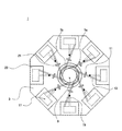
なお、連結路13、収容空間17及び排気路19については、図3の上面図では本来視認できないものであるが、発明の理解を容易にするため、図中に点線で示してある。
FIG. 1 to FIG. 3 are diagrams for explaining a separation device according to the first embodiment of the present invention, and FIG. 1 is a perspective view of the separation device according to the first embodiment of the present invention as seen obliquely from above. 2 is a cross-sectional view of the separation apparatus according to the first embodiment of the present invention, and FIG. 3 is an explanatory view of the separation apparatus according to the first embodiment of the present invention as viewed from above.
Note that the connection path 13, the accommodation space 17, and the exhaust path 19 are originally not visible in the top view of FIG. 3, but are shown by dotted lines in the drawing for easy understanding of the invention.

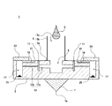
図1に示すように、本実施形態の分離装置1は、横断面形状が略正八角形をした板状の本体3と、この本体3の上面中央部に鉛直上方に向けて設けられた円筒状の軸部5と、本体3の下面中央部に設けられ、鉛直下方に頂点を向けて設けられた錐形の接地部7と、を主要な構成要素として備えている。   As shown in FIG. 1, the separation device 1 according to the present embodiment includes a plate-like main body 3 having a substantially regular octagonal cross-sectional shape, and a cylindrical shape provided vertically upward at the center of the upper surface of the main body 3. The shaft portion 5 and a conical grounding portion 7 provided at the center of the lower surface of the main body 3 and facing the apex vertically downward are provided as main components.

本体3は、樹脂,金属,セラミックス等の公知の材料を用いて形成される部材である。本実施形態では、本体3は直径2〜3cmの略八角形をした板状部材であるが、本体3の大きさや形状としては本実施形態のものに限定されない。例えば形状であれば、正十六角形等の他の多角形の形状であってもよく、あるいは円形のものであってもよい。また、本体3の外装には、ニッケルや金メッキを施してもよい。
図2に示すように、本体3は、上面中央部から本体3の中心部に向かって直径5mm程度の中空部9が形成されており、外部から導入された血液等の検体を収容可能となっている。
The main body 3 is a member formed using a known material such as resin, metal, or ceramics. In the present embodiment, the main body 3 is a plate member having a substantially octagonal shape with a diameter of 2 to 3 cm, but the size and shape of the main body 3 are not limited to those of the present embodiment. For example, as long as it is a shape, it may be another polygonal shape such as a regular hexagon or a circular shape. The exterior of the main body 3 may be plated with nickel or gold.
As shown in FIG. 2, the main body 3 is formed with a hollow portion 9 having a diameter of about 5 mm from the central portion of the upper surface toward the central portion of the main body 3, and can accommodate a specimen such as blood introduced from the outside. ing.

図3に示すように、中空部9からは、本体3の外方に向かって放射状に複数の連結路13が形成されており、連結路13と一対一に設けられた複数の収容空間17に夫々連通している。連結路13の途中には後述する分離部材11が連結路を遮蔽する位置に配置されている。
また、図2に示すように、連結路13は、中空部9から分離部材11まで連通する第一の連結路13aと、分離部材11から収容空間17まで連通する第二の連結路13bにより形成されている。
As shown in FIG. 3, a plurality of connection paths 13 are formed radially from the hollow portion 9 toward the outside of the main body 3, and a plurality of receiving spaces 17 provided one-on-one with the connection paths 13. Each communicates. In the middle of the connecting path 13, a separating member 11 described later is arranged at a position that shields the connecting path.
As shown in FIG. 2, the connection path 13 is formed by a first connection path 13 a that communicates from the hollow portion 9 to the separation member 11 and a second connection path 13 b that communicates from the separation member 11 to the accommodation space 17. Has been.

第一の連結路13aは、直径略500μmの細管であり、本体3の中空部9から横方向に垂直に形成されている。
また、第二の連結路13bは、直径略100μmの細管であり、第一の連結路13aと分離部材11を挟んで連続して形成されている。細管の直径としては、100μm〜200μm程度が好ましく、より好適には150μm程度がよい。
このように、第一の連結路13aは第二の連結路13bよりも大径となっているため、分離部材11で分離された固体成分により連結路13の目詰まりが防止される。
The first connection path 13 a is a thin tube having a diameter of about 500 μm, and is formed vertically from the hollow portion 9 of the main body 3 in the lateral direction.
The second connection path 13b is a thin tube having a diameter of about 100 μm, and is continuously formed with the first connection path 13a and the separation member 11 interposed therebetween. The diameter of the thin tube is preferably about 100 μm to 200 μm, and more preferably about 150 μm.
Thus, since the first connecting path 13a has a larger diameter than the second connecting path 13b, the clogging of the connecting path 13 is prevented by the solid component separated by the separating member 11.

更に、連結路13には、血液中の生体成分が壁面に付着することを防止するコーティング剤を塗布することが好ましい。このようなコーティング剤として特に好適なものが、2―メタクリロイルオキシエチルホスホリルコリン(MPC)を単量体成分として構成された共重合体である。このような共重合体の例としては、2―メタクリロイルオキシエチルホスホリルコリン(MPC)とメタクリル酸エステルの共重合体等が挙げられる。   Furthermore, it is preferable to apply a coating agent to the connection path 13 to prevent biological components in blood from adhering to the wall surface. Particularly suitable as such a coating agent is a copolymer composed of 2-methacryloyloxyethyl phosphorylcholine (MPC) as a monomer component. Examples of such a copolymer include a copolymer of 2-methacryloyloxyethyl phosphorylcholine (MPC) and a methacrylic acid ester.

収容空間17は、本体3の外周部に画設されており、連結路13から流入する液体を収容することが可能となっている。収容空間17は、略四角柱状の孔として形成されており、分離装置1の後述する回転軸線Zを中心として中空部9よりも外方に画設されている。本実施形態では、収容空間17は、横断面形状が正八角形の本体3のそれぞれの辺に対応する位置に一つずつ形成されている。ただし、収容空間17としては、このように本体3の各辺に対応する位置に形成されるものに限定されず、例えば正八角形状をした本体3であっても、収容空間17は2箇所のみ設けられるものであってもよい。   The accommodation space 17 is provided on the outer peripheral portion of the main body 3 and can accommodate the liquid flowing in from the connection path 13. The accommodation space 17 is formed as a substantially quadrangular columnar hole, and is provided outside the hollow portion 9 around a rotation axis Z (described later) of the separation device 1. In the present embodiment, one accommodation space 17 is formed at a position corresponding to each side of the main body 3 having a regular octagonal cross-sectional shape. However, the accommodation space 17 is not limited to the one formed in the position corresponding to each side of the main body 3 as described above. For example, even if the main body 3 has a regular octagonal shape, the accommodation space 17 has only two places. It may be provided.

収容空間17には、検体中の所定の成分と反応する薬剤25が収容されている。薬剤の種類としては、例えば血液中に含まれるウイルス等の抗原と反応して凝集する担体感作抗体や、血漿中に含まれる所定の成分と反応する試薬等が挙げられる。   The storage space 17 stores a drug 25 that reacts with a predetermined component in the specimen. Examples of the drug include carrier-sensitized antibodies that react and aggregate with antigens such as viruses contained in blood, and reagents that react with predetermined components contained in plasma.

収容空間17の上部開口には、収容空間17の液体が収容空間17の外へ飛散することを防止するため蓋体23が覆設されている。蓋体23は、樹脂製の透明部材あるいは半透明部材で構成され、分離された検体を測定するための測定光等を透過可能となっている。   A lid body 23 is covered with the upper opening of the storage space 17 in order to prevent the liquid in the storage space 17 from splashing out of the storage space 17. The lid 23 is made of a resin-made transparent member or translucent member, and can transmit measurement light or the like for measuring the separated specimen.

分離部材11は方形状のフィルターであり、血液等の検体から血漿等の所定の成分を透過する分離機能を有している。分離部材11は、本体3の上部に形成された挿入孔から差し込むことで本体3に取りつけられる。
本実施形態では、複数の連結路13毎に分離部材11を取りつけることが可能に構成されているため、分離性能の異なる分離部材11を連結路13に設けることで、一度の操作で同時に異なる成分や同じ成分であっても異なる組成で分離することが可能となる。
The separation member 11 is a rectangular filter and has a separation function of transmitting a predetermined component such as plasma from a specimen such as blood. The separation member 11 is attached to the main body 3 by being inserted from an insertion hole formed in the upper portion of the main body 3.
In the present embodiment, since the separation member 11 can be attached to each of the plurality of connection paths 13, by providing the connection path 13 with the separation members 11 having different separation performance, different components can be simultaneously performed by one operation. Even the same components can be separated with different compositions.

収容空間17の上部内壁からは、内部に存在する気体成分を除去する排気路19が本体3の中心方向に向かって形成されている。排気路19は、本体3の上面に形成された排気孔21に連通しており、収容空間17内に存在する空気や収容空間17内で発生するガスは、この排気孔21から外へ排気される。   From the upper inner wall of the accommodation space 17, an exhaust path 19 for removing a gas component existing inside is formed toward the center of the main body 3. The exhaust passage 19 communicates with an exhaust hole 21 formed on the upper surface of the main body 3, and air existing in the accommodation space 17 and gas generated in the accommodation space 17 are exhausted to the outside from the exhaust hole 21. The

続いて、軸部5について説明する。本実施形態の軸部5は、樹脂,金属,セラミックス等の公知の材料を用いて形成される管状部材であり、本実施形態では内部に管路5cが形成された円筒形状をしている。軸部5は、円筒形状をした円筒部5aと、円筒部5aの一端に形成されるフランジ5bにより構成される。フランジ5bは、円筒部5aの長手方向に対して横方向に向けて略垂直に延出した状態に形成されている。このフランジ5bは、軸部5を本体3に止着する際の止着面としての役割を果たす。本体3の上面とフランジ5bとは、接着剤等の公知の固着手段を用いて固着することが可能である。   Subsequently, the shaft portion 5 will be described. The shaft portion 5 of the present embodiment is a tubular member formed using a known material such as resin, metal, ceramics, etc., and in the present embodiment, has a cylindrical shape in which a pipe line 5c is formed. The shaft part 5 includes a cylindrical part 5a having a cylindrical shape and a flange 5b formed at one end of the cylindrical part 5a. The flange 5b is formed in a state extending substantially perpendicularly in the lateral direction with respect to the longitudinal direction of the cylindrical portion 5a. The flange 5b serves as a fastening surface when the shaft portion 5 is fastened to the main body 3. The upper surface of the main body 3 and the flange 5b can be fixed using a known fixing means such as an adhesive.

本体3と軸部5とが固着されると、軸部5の管路5cと本体3の中空部9が連通する。すなわち、軸部5の一端に形成されている開口から本体3の中空部9に通じる通路が形成される。管路5cは、後述するように検体を中空部9に導入するための通路としての機能を有している。   When the main body 3 and the shaft portion 5 are fixed, the conduit 5c of the shaft portion 5 and the hollow portion 9 of the main body 3 communicate with each other. That is, a passage from the opening formed at one end of the shaft portion 5 to the hollow portion 9 of the main body 3 is formed. The pipe line 5c has a function as a passage for introducing the specimen into the hollow portion 9, as will be described later.

接地部7は、樹脂,金属,セラミックス等の公知の材料を用いて形成される部材であり、本実施形態では円錐形状をした部材として形成されている。接地部7は、その頂点を鉛直下方向に向け、円錐の底面を本体3の底面中央部の板面と固着することで本体3に取り付けられている。本体3と接地部7とは接着剤等の公知の固着手段を用いて固着することが可能である。
なお、接地部7の形状としては、本実施形態のような円錐形状のものに限定されず、例えば多角錐形状等であってもよい。
The grounding portion 7 is a member formed using a known material such as resin, metal, ceramics, and is formed as a conical member in this embodiment. The grounding portion 7 is attached to the main body 3 by turning its apex vertically downward and fixing the bottom surface of the cone to the plate surface at the center of the bottom surface of the main body 3. The main body 3 and the grounding portion 7 can be fixed using a known fixing means such as an adhesive.
In addition, as a shape of the grounding part 7, it is not limited to the thing of a cone shape like this embodiment, For example, a polygonal pyramid shape etc. may be sufficient.

本実施形態では、軸部5及び接地部7は本体3とは別部材として設け、これらを本体3に止着する構成としているが、本発明の軸部及び接地部としてはこのような構成に限定されず、本体3と一体に形成してもよい。   In the present embodiment, the shaft portion 5 and the grounding portion 7 are provided as separate members from the main body 3, and are configured to be fixed to the main body 3. However, the shaft portion and the grounding portion of the present invention have such a configuration. It is not limited, You may form integrally with the main body 3.

本発明の分離装置1は、軸部5の長手方向での中心軸線と、接地部7の頂点7aとを結ぶ軸線を回転軸線Zとして、接地部7の頂点7aを接地した状態で回転軸線Zを中心にコマのように回転可能となっている。よって、軸部5を指でつまんで回転力を加えることにより、接地部7の頂点7aを台等の平面に接地した状態でコマのように回転させることが可能となっている。中空部9に血液等の検体を収容した状態で、分離装置1を回転させることにより、収容された検体に遠心力がかかり、検体中の固体成分が沈殿し、液体成分が上澄みとなる。具体的には、検体が血液の場合にあっては、中空部9の底部に血球成分が沈殿する一方、血漿成分が上澄みとなる。   The separation device 1 of the present invention has a rotation axis Z in a state where the axis connecting the central axis in the longitudinal direction of the shaft 5 and the vertex 7a of the grounding portion 7 is the rotation axis Z, and the vertex 7a of the grounding portion 7 is grounded. It can be rotated like a frame around the center. Therefore, by pinching the shaft portion 5 with a finger and applying a rotational force, the apex 7a of the grounding portion 7 can be rotated like a frame while being grounded on a plane such as a table. When the separation device 1 is rotated in a state where a sample such as blood is stored in the hollow portion 9, a centrifugal force is applied to the stored sample, the solid component in the sample is precipitated, and the liquid component becomes the supernatant. Specifically, when the sample is blood, the blood cell component is precipitated at the bottom of the hollow portion 9, while the plasma component is the supernatant.

血漿成分は更に、連結路13を通過して収容空間17に移動しようとする。本実施形態では、連結路13には分離部材11が連結路13の一部を遮蔽する位置に設けられているため、上澄み中に含まれる残存血球成分の通過が阻止されて、血漿成分のみ分離部材11を通過して収容空間17に移動する。
このように、本実施形態の分離装置1は、遠心力により血液から血漿成分を分離するのみならず、分離部材11が連結路13の一部を遮断する位置に設けられているため、血漿成分をより確実に分離することが可能となっている。
The plasma component further tries to move to the accommodation space 17 through the connection path 13. In the present embodiment, since the separation member 11 is provided in the connection path 13 at a position where a part of the connection path 13 is shielded, the passage of residual blood cell components contained in the supernatant is prevented, and only the plasma component is separated. It passes through the member 11 and moves to the accommodation space 17.
As described above, the separation device 1 according to this embodiment not only separates the plasma component from the blood by centrifugal force, but also the separation member 11 is provided at a position where a part of the connection path 13 is blocked. Can be more reliably separated.

収容空間17には検体中の成分と反応する薬剤25が収容されており、分離装置1が回転している間に、分離された血漿成分中の所定の成分と混合されて反応する。蓋体23は透明又は半透明であるため、蓋体23越しに反応後の溶液を分光学的に測定することが可能となっており、従って、蓋体23を取り外すことなく簡単な操作で、後述の分析装置などを用いて反応後の溶液を測定することができる。   The storage space 17 stores a drug 25 that reacts with the components in the specimen, and while the separation device 1 is rotating, it is mixed with a predetermined component in the separated plasma component and reacts. Since the lid body 23 is transparent or translucent, the solution after the reaction can be measured spectroscopically through the lid body 23. Therefore, the lid body 23 can be easily operated without removing the lid body 23. The solution after the reaction can be measured using an analyzer described later.

続いて、本発明の第二の実施形態に係る分離装置について説明する。図4及び図5は、本発明の第二の実施形態に係る分離装置を説明した図であり、図4は本発明の第二の実施形態に係る分離装置の横断面図、図5は本発明の第二の実施形態に係る分離装置を上面からみた説明図である。
なお、連結路13、収容空間17及び排気路19については、図5の上面図では本来視認できないものであるが、発明の理解を容易にするため、図中に点線で示してある。
Subsequently, a separation device according to a second embodiment of the present invention will be described. 4 and 5 are diagrams illustrating a separation device according to the second embodiment of the present invention. FIG. 4 is a cross-sectional view of the separation device according to the second embodiment of the present invention, and FIG. It is explanatory drawing which looked at the separation apparatus which concerns on 2nd embodiment of invention from the upper surface.
Note that the connection path 13, the accommodation space 17, and the exhaust path 19 are originally not visible in the top view of FIG. 5, but are shown by dotted lines in the drawing for easy understanding of the invention.

図4に示すように、本実施形態の分離装置は、第一の実施形態の分離装置と同様に、横断面形状が略正八角形をした板状の本体3と、この本体3の上面中央部に鉛直上方に向けて設けられた円筒状の軸部5と、本体3の下面中央部に設けられ、鉛直下方に頂点を向けて設けられた錐形の接地部7と、を主要な構成要素として備えている。
本実施形態では第一の実施形態の場合と異なり、図4に示すように、軸部5と接地部7とは一体の部材として形成されており、本体3の中心部に設けられた貫通孔に軸部5を貫挿することで本体3に取りつけられている。
As shown in FIG. 4, the separation device of the present embodiment is similar to the separation device of the first embodiment in that the plate-like main body 3 whose cross-sectional shape is a substantially regular octagon, and the central portion of the upper surface of the main body 3. A cylindrical shaft portion 5 provided vertically upward and a cone-shaped grounding portion 7 provided at the center of the lower surface of the main body 3 with the apex directed vertically downward. As prepared.
In this embodiment, unlike the case of the first embodiment, as shown in FIG. 4, the shaft portion 5 and the grounding portion 7 are formed as an integral member, and a through hole provided in the center portion of the main body 3. It is attached to the main body 3 by inserting the shaft portion 5 therethrough.

本体3は、第一の実施形態における本体と略同等の形状や構造を有しているが、第一の実施形態のように中空部9が本体3の中心に一箇所設けられているのではなく、本実施形態では図4及び図5に示すように、本体3の中心部周辺に複数の中空部9が同心円状に設けられている。そして、これら複数の中空部9からは夫々第一の連結路13a及び第二の連結路13bが形成されており、第二の連結路13bは夫々単一の収容空間17に連通している。
第一の連結路13aと第二の連結路13bとの間には、第一の実施形態と同様に、分離部材11が配設されている。第一の実施形態と同様に、中空部9の検体は、分離部材11により所定の成分に分離される。
The main body 3 has substantially the same shape and structure as the main body in the first embodiment, but the hollow portion 9 is not provided in one place in the center of the main body 3 as in the first embodiment. Instead, in this embodiment, as shown in FIGS. 4 and 5, a plurality of hollow portions 9 are provided concentrically around the central portion of the main body 3. A first connection path 13 a and a second connection path 13 b are formed from the plurality of hollow portions 9, respectively. The second connection path 13 b communicates with a single accommodation space 17.
As in the first embodiment, the separation member 11 is disposed between the first connection path 13a and the second connection path 13b. As in the first embodiment, the specimen in the hollow portion 9 is separated into predetermined components by the separation member 11.

本実施形態の分離装置1は、上述のように中空部9を複数備えているため、図4のように、夫々の中空部毎に異なる種類の検体S1および検体S2を収容することが可能となっている。具体的には、例えば複数の患者からの血液を夫々の中空部9に収容して、一度に血漿分離工程及び反応工程を行うことが可能である。従って、血液検査に要する時間や手間を省略することが可能となり、効率よく検査を実施することが可能となっている。   Since the separation apparatus 1 of the present embodiment includes a plurality of hollow portions 9 as described above, it is possible to accommodate different types of samples S1 and S2 for each hollow portion as shown in FIG. It has become. Specifically, for example, blood from a plurality of patients can be accommodated in the respective hollow portions 9, and the plasma separation step and the reaction step can be performed at once. Therefore, the time and labor required for the blood test can be omitted, and the test can be performed efficiently.

続いて、本発明の第三の実施形態に係る分離装置について説明する。図6及び図7は、本発明の第三の実施形態に係る分離装置を説明した図であり、図6は本発明の第三の実施形態に係る分離装置の横断面図、図7は本発明の第三の実施形態に係る分離装置を上面からみた説明図である。
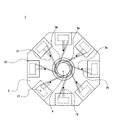
なお、連結路15、収容空間17及び排気路19については、図7の上面図では本来視認できないものであるが、発明の理解を容易にするため、図中に点線で示してある。
Subsequently, a separation device according to a third embodiment of the present invention will be described. 6 and 7 are diagrams illustrating a separation device according to a third embodiment of the present invention. FIG. 6 is a cross-sectional view of the separation device according to the third embodiment of the present invention. FIG. It is explanatory drawing which looked at the separation apparatus which concerns on 3rd embodiment of invention from the upper surface.
Note that the connection path 15, the accommodation space 17, and the exhaust path 19 are originally not visible in the top view of FIG. 7, but are shown by dotted lines in the drawing for easy understanding of the invention.

本実施形態の分離装置は、第一の実施形態の分離装置と同様に、横断面形状が略正八角形をした板状の本体3と、この本体3の上面中央部に鉛直上方に向けて設けられた円筒状の軸部5と、本体3の下面中央部に設けられ、鉛直下方に頂点を向けて設けられた錐形の接地部7と、を主要な構成要素として備えている。   Similar to the separation device of the first embodiment, the separation device of the present embodiment is provided with a plate-like main body 3 having a substantially regular octagonal cross-sectional shape and a vertically upper portion at the center of the upper surface of the main body 3. The cylindrical shaft portion 5 and the conical grounding portion 7 provided at the center of the lower surface of the main body 3 with the apex facing vertically downward are provided as main components.

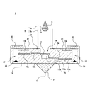
本体3は、第一の実施形態における本体と略同等の形状や構造を有しており、中空部9は、本体3の上面中央部に形成されている。第一の実施形態との相違点は、第一の実施形態では分離部材11が連結路15の夫々に対して配設されているのに対して、本実施形態では図7に示すように、中空部9の下側に隔室15aが形成されており、この隔室15aと中空部9の間に第一の分離部材としての分離部材11が設けられている点である。すなわち、本実施形態では、共通の分離部材としての単一の分離部材11が設けられている。このような構成とすることで、複数の分離部材を設ける必要がなく、分離装置の製造コストを下げることが可能となっている。   The main body 3 has substantially the same shape and structure as the main body in the first embodiment, and the hollow portion 9 is formed at the center of the upper surface of the main body 3. The difference from the first embodiment is that, in the first embodiment, the separation member 11 is arranged for each of the connecting paths 15, whereas in the present embodiment, as shown in FIG. A compartment 15 a is formed below the hollow portion 9, and a separation member 11 as a first separation member is provided between the compartment 15 a and the hollow portion 9. That is, in this embodiment, the single separation member 11 as a common separation member is provided. With such a configuration, it is not necessary to provide a plurality of separation members, and the manufacturing cost of the separation device can be reduced.

また、本実施形態の本体3は、血液から所定の成分を分離することが可能な部材で構成されている。本実施形態では、具体的には多孔質セラミックスで形成されている。多孔質セラミックスには、血液中の血漿成分を通過させるが血球成分の通過を阻止する大きさの孔が複数形成されており、血漿成分を分離する機能を備えている。   Moreover, the main body 3 of this embodiment is comprised with the member which can isolate | separate a predetermined component from the blood. In this embodiment, specifically, it is made of porous ceramics. The porous ceramics is formed with a plurality of pores having a size that allows the plasma component in the blood to pass but prevents the passage of the blood cell component, and has a function of separating the plasma component.

隔室15aは、中空部9よりも直径の小さい円筒状の小室である。また、分離部材11は、直径が中空部9と略等しい円板状のフィルターであり、第一の実施形態と同様に血液等の検体から血漿等の所定の成分を透過する分離機能を有している。分離部材11は、中空部9と隔室15aとの間の縮径した縁部に、分離部材11の周縁部が圧着された状態で配置される。   The compartment 15 a is a cylindrical small chamber having a smaller diameter than the hollow portion 9. Further, the separation member 11 is a disc-shaped filter having a diameter substantially equal to that of the hollow portion 9, and has a separation function of transmitting a predetermined component such as plasma from a specimen such as blood as in the first embodiment. ing. The separation member 11 is disposed in a state where the peripheral edge portion of the separation member 11 is crimped to the edge having a reduced diameter between the hollow portion 9 and the compartment 15a.

図7に示すように、隔室15a(図7中では不図示)からは、本体3の外方に向かって放射状に第一の連結路15b及び第二の連結路15cからなる複数の連結路が形成されており、この連結路と一対一に設けられた複数の収容空間17に夫々連通している。図6に示すように、連結路15b及び連結路15cの間には後述する第二の分離部材である分離領域3aが連結路15b及び連結路15cの間を遮蔽する位置に配置されている。
なお、隔室15a、第一の連結路15b、第二の連結路15cは、本発明の連結路15を構成する。
As shown in FIG. 7, from the compartment 15a (not shown in FIG. 7), there are a plurality of connecting paths that are radially formed from the first connecting path 15b and the second connecting path 15c toward the outside of the main body 3. Are formed and communicated with a plurality of accommodating spaces 17 provided one-on-one with the connecting path. As illustrated in FIG. 6, a separation region 3 a that is a second separation member described later is disposed between the coupling path 15 b and the coupling path 15 c at a position that shields between the coupling path 15 b and the coupling path 15 c.
In addition, the compartment 15a, the 1st connection path 15b, and the 2nd connection path 15c comprise the connection path 15 of this invention.

第一の連結路15bは、隔室15aから後述する分離領域3aに連通している。分離領域3aは、本体3の一部の領域であり、本体3と同じく多孔質セラミックスで形成されている。分離領域を挟んで、第一の連結路15bと対向する位置に第二の連結路15cが形成され、収容空間17へ連通している。   The first connecting path 15b communicates with the separation region 3a described later from the compartment 15a. The separation region 3 a is a partial region of the main body 3 and is formed of porous ceramics as with the main body 3. A second connection path 15 c is formed at a position facing the first connection path 15 b across the separation region, and communicates with the accommodation space 17.

第一の連結路15bの端部と第二の連結路15cの端部との間は短く離間している。すなわち、図6に示すように、第一の連結路15bと第二の連結路15cの間には、本体3の一部の領域である分離領域3aが形成されている。分離領域3aは本体3の一部であるため、本体3と同様に多孔質セラミックスで形成されている。すなわち、分離領域3aでは、血漿成分を通すが血球成分を通さないため、分離領域3aは血漿成分を分離する分離部材11と同様の作用を備えている。   The end of the first connecting path 15b and the end of the second connecting path 15c are short apart. That is, as shown in FIG. 6, a separation region 3 a that is a partial region of the main body 3 is formed between the first connection passage 15 b and the second connection passage 15 c. Since the separation region 3 a is a part of the main body 3, it is made of porous ceramics like the main body 3. That is, in the separation region 3a, the plasma component is passed but the blood cell component is not passed. Therefore, the separation region 3a has the same function as the separation member 11 that separates the plasma component.

このように、本実施形態の分離装置は、分離部材11と第二の分離部材である分離領域3aの2つの分離部材を備えているため、分離装置1の回転により完全には分離できなかった血球成分を分離部材11で除去することができると共に、この第一の分離部材11でも除去できずに漏出した血球成分を、更に第二の分離部材である分離領域3aで除去することが可能となっている。従って、より確実に血球成分を除去することが可能となっている。   As described above, since the separation device of the present embodiment includes the two separation members of the separation member 11 and the separation region 3a that is the second separation member, the separation device 1 could not be completely separated by the rotation of the separation device 1. The blood cell component can be removed by the separation member 11, and the blood cell component leaked without being removed by the first separation member 11 can be further removed by the separation region 3a which is the second separation member. It has become. Therefore, it is possible to remove blood cell components more reliably.

また、本実施形態の分離装置は、本体3が検体から所定の成分を分離可能な材料から構成されると共に、その一部により分離領域3aが形成されている。すなわち、本体3の一部を分離部材として使用している。従って、別体として分離部材を用意してこれを連結路に設置するという手間を必要とせず、分離装置の製造にかかる手間を簡略化することが可能であると共に、分離装置の構造をより簡単なものとすることができる。   In the separation apparatus of the present embodiment, the main body 3 is made of a material capable of separating a predetermined component from a specimen, and a separation region 3a is formed by a part thereof. That is, a part of the main body 3 is used as a separating member. Therefore, it is not necessary to prepare a separating member as a separate body and install it in the connecting path, and it is possible to simplify the labor involved in manufacturing the separating device and to simplify the structure of the separating device. Can be.

続いて、本発明の第四の実施形態に係る分離装置について説明する。図8及び図9は、本発明の第四の実施形態に係る分離装置を説明した図であり、図8は本発明の第四の実施形態に係る分離装置の横断面図、図9は本発明の第四の実施形態に係る分離装置に回転力を付与する回転力付与装置の斜視図である。   Subsequently, a separation device according to a fourth embodiment of the present invention will be described. 8 and 9 are diagrams illustrating a separation device according to a fourth embodiment of the present invention. FIG. 8 is a cross-sectional view of the separation device according to the fourth embodiment of the present invention. FIG. It is a perspective view of the rotational force provision apparatus which provides rotational force to the separation apparatus which concerns on 4th embodiment of invention.

本実施形態の分離装置1は、図8に示すように、第一の実施形態と異なり軸部を備えておらず、分離装置1を手で回すのではなく回転力付与装置としてのシューター40を用いて回す点に特徴がある。
分離装置1の本体3の下面には、後述するシューター40の回転体42に形成された係合部42aと係合する形状の切欠部(図示せず)が形成されており、シューター40の回転体42に載置される。
As shown in FIG. 8, the separation device 1 of the present embodiment does not include a shaft portion unlike the first embodiment, and instead of turning the separation device 1 by hand, a shooter 40 as a rotational force applying device is provided. It is characterized in that it is used and rotated.
On the lower surface of the main body 3 of the separating apparatus 1, a notch portion (not shown) is formed to engage with an engaging portion 42 a formed on a rotating body 42 of the shooter 40 described later. It is placed on the body 42.

本実施形態のシューター40は、分離装置1を保持し、これに回転力を与えてコマのように回転させる装置である。このようなシューターは、玩具のコマを回すための回転力付与装置として公知のものである。本実施形態のシューター40としては、このような玩具の回転力付与装置としてのシューターを転用することも可能である。   The shooter 40 of the present embodiment is a device that holds the separation device 1 and applies a rotational force to the separation device 1 to rotate it like a top. Such a shooter is known as a rotational force imparting device for turning a toy piece. As the shooter 40 of this embodiment, it is also possible to divert such a shooter as a toy rotational force applying device.

本実施形態のシューター40は、図9に示すように、シューター本体41とラックベルト50を主要な構成要素として備えている。シューター本体41は略方形をした中空部材で構成され、シューター本体41の側面にはラックベルト50を挿通可能な開口41aが形成されている。また、シューター本体41内には図示しない軸体が設けられている。この軸体には、ラックベルト50のラックギヤ50aと噛合する図示しないピニオンギヤが回動可能に設けられている。ラックギヤ50aは回転体42と連結しており、この回転体42には、前述のように分離装置1の切欠部と係合する形状の係合部42aが形成されている。シューター本体41の上面中央部には円形の開口が設けられており、係合部42aが形成された回転体42の一部領域が露出している。   As shown in FIG. 9, the shooter 40 of the present embodiment includes a shooter body 41 and a rack belt 50 as main components. The shooter main body 41 is configured by a substantially square hollow member, and an opening 41 a through which the rack belt 50 can be inserted is formed on a side surface of the shooter main body 41. A shaft body (not shown) is provided in the shooter body 41. A pinion gear (not shown) that meshes with the rack gear 50a of the rack belt 50 is rotatably provided on the shaft body. The rack gear 50a is connected to the rotating body 42. The rotating body 42 is formed with the engaging portion 42a having a shape that engages with the notch portion of the separating device 1 as described above. A circular opening is provided at the center of the upper surface of the shooter body 41, and a partial region of the rotating body 42 in which the engaging portion 42a is formed is exposed.

続いて、本実施形態の分離装置1を回転する手順について説明する。まず、ラックベルト50を開口41aからシューター本体41内に挿入して、ラックギヤ50aとピニオンギヤが噛合するようにする。この状態で、分離装置1をシューター本体41の上面に載置して、分離装置1の本体3下面に形成された切欠部を回転体42の係合部42aに係合する。   Subsequently, a procedure for rotating the separation device 1 of the present embodiment will be described. First, the rack belt 50 is inserted into the shooter main body 41 from the opening 41a so that the rack gear 50a and the pinion gear mesh. In this state, the separating device 1 is placed on the upper surface of the shooter main body 41, and the notch formed on the lower surface of the main body 3 of the separating device 1 is engaged with the engaging portion 42a of the rotating body 42.

そして、分離装置1と係合部42aが係合した状態で、ラックベルト50の環状部に指をかけてラックベルト50をシューター本体41から思いっきり引き抜くと、ラックベルト50のラックギヤ50aと係合したピニオンギヤが軸体を中心に回転する。ピニオンギヤは回転体42の一部であるため、ラックベルト50を引き抜くことにより、回転力がピニオンギヤから回転体42に伝わる。回転体42が回転すると、回転体42と係合した分離装置1が回転して、その力で分離装置1の切欠部と回転体42の係合部42aの係合が解除され、分離装置1がシューター40から離脱して、分離装置1の接地部の頂点を支点として机上等の平面上で回転する。
分離装置1内には他の実施形態と同様に、中空部に検体である液体が収容されているため、分離装置1の回転に伴い液体中の成分が分離される。
Then, when the separating device 1 and the engaging portion 42a are engaged, when the rack belt 50 is pulled out from the shooter body 41 by placing a finger on the annular portion of the rack belt 50, the rack gear 50a of the rack belt 50 is engaged. The pinion gear rotates around the shaft. Since the pinion gear is a part of the rotating body 42, when the rack belt 50 is pulled out, the rotational force is transmitted from the pinion gear to the rotating body 42. When the rotating body 42 rotates, the separating device 1 engaged with the rotating body 42 rotates, and the engagement between the notch portion of the separating device 1 and the engaging portion 42a of the rotating body 42 is released by the force, and the separating device 1 Detaches from the shooter 40 and rotates on a plane such as a desk with the apex of the grounding portion of the separation device 1 as a fulcrum.
As in the other embodiments, since the liquid that is the specimen is stored in the hollow portion in the separation device 1, the components in the liquid are separated as the separation device 1 rotates.

このように、本実施形態の分離装置1では、分離装置1に回転力を付与する回転力付与装置を用いて分離装置1を回転させている。このため、他の実施形態のように手で分離装置1を回す場合と異なり、操作者が分離装置1を上手く回せない場合においても好適に分離装置1を回転させることが可能となっている。   As described above, in the separation device 1 of the present embodiment, the separation device 1 is rotated using the rotational force applying device that applies the rotational force to the separation device 1. For this reason, unlike the case where the separation device 1 is manually rotated as in the other embodiments, the separation device 1 can be suitably rotated even when the operator cannot turn the separation device 1 well.

すなわち、本実施形態では、回転力付与装置を用いて分離装置1を回転させているため、分離装置1の回転のさせ方がわからない人であっても分離装置1を回転することが可能である。また、分離装置1を回転する人の技量や力加減によらず、略均一な遠心力を検体に付加することが可能となるため、再現性よく検体から所定の成分を分離することが可能となっている。   That is, in this embodiment, since the separation device 1 is rotated using the rotational force applying device, the separation device 1 can be rotated even by a person who does not know how to rotate the separation device 1. . Further, since it is possible to apply a substantially uniform centrifugal force to the specimen regardless of the skill and force of the person who rotates the separation device 1, it is possible to separate a predetermined component from the specimen with high reproducibility. It has become.

以上、本発明の分離装置について複数の実施形態を挙げて説明した。上記各実施形態の分離装置はいずれも錐形の接地部の頂点で机等の平面状に接地した状態で回転するものであるが、本発明の分離装置はこのような形態のものに限定されず、例えばジャイロスコープのように、複数の環状部材の中心部に本実施形態のコマを設置し、これを回転するものであってもよい。   Hereinabove, the separation apparatus of the present invention has been described with reference to a plurality of embodiments. Each of the separation devices of the above embodiments rotates in a state where it is grounded on a flat surface such as a desk at the apex of the conical grounding portion, but the separation device of the present invention is limited to such a configuration. Instead, for example, like the gyroscope, the top of the present embodiment may be installed at the center of a plurality of annular members and rotated.

更に、測定手段を備えた分析装置に本発明の分離装置1を設置して、分離後の検体を測定する構成としてもよい。
図10は本発明の測定装置60の横断面図である。図10に示すように、本実施形態の測定装置60は、分離装置1と、分析装置を備えている。分析装置は、図示しないケースと、光源62と、投光側光ファイバ63と、投光ヘッド64と、集光レンズ65と、受光ヘッド66と、受光側光ファイバ67と、分光部68と、コンピュータ69を主要な構成要素として備えている。本実施形態では、光源62と、投光側光ファイバ63と、投光ヘッド64と、集光レンズ65と、受光ヘッド66と、受光側光ファイバ67と、分光部68については、ケース内に収容されている。
なお、分析装置は本発明における測定手段に該当する。
Furthermore, the separation apparatus 1 of the present invention may be installed in an analyzer equipped with a measuring means to measure a sample after separation.
FIG. 10 is a cross-sectional view of the measuring apparatus 60 of the present invention. As shown in FIG. 10, the measuring device 60 of the present embodiment includes a separation device 1 and an analysis device. The analyzer includes a case (not shown), a light source 62, a light projecting side optical fiber 63, a light projecting head 64, a condenser lens 65, a light receiving head 66, a light receiving side optical fiber 67, a spectroscopic unit 68, A computer 69 is provided as a main component. In the present embodiment, the light source 62, the light projecting side optical fiber 63, the light projecting head 64, the condensing lens 65, the light receiving head 66, the light receiving side optical fiber 67, and the spectroscopic unit 68 are included in the case. Contained.
The analyzer corresponds to the measuring means in the present invention.

本実施形態の測定装置60は、上記各実施形態に記載された分離装置1を構成要素の一部として備えている。すなわち、分離装置1は、前述のように分離装置1の中空部9に検体を収容した状態で分離装置1をコマのように回すことで、所望の成分を含む分離後の検体S3が収容空間17に分離される。そして、本実施形態では、この分離操作を行った後の分離装置1を分析装置の所定の位置にセットして、収容空間17に収容された分離後の検体S3に対して光学測定などの測定を行うことにより、分離後の検体中に含まれる所定成分の濃度などが測定可能となっている。   The measuring device 60 of the present embodiment includes the separation device 1 described in each of the above embodiments as a part of the constituent elements. That is, the separation device 1 rotates the separation device 1 like a frame in a state where the sample is accommodated in the hollow portion 9 of the separation device 1 as described above, so that the separated sample S3 containing a desired component is contained in the accommodation space. 17 is separated. In this embodiment, the separation device 1 after performing this separation operation is set at a predetermined position of the analyzer, and measurement such as optical measurement is performed on the separated sample S3 accommodated in the accommodation space 17. By performing the above, it is possible to measure the concentration of a predetermined component contained in the sample after separation.

光源62は、電源から供給される電力によって白色光を発する装置である。光源62には投光側光ファイバ63が接続されており、光源62で発した光は投光側光ファイバ63の一端に入射する。投光側光ファイバ63の他端には投光ヘッド64が接続されている。投光ヘッド64は集光レンズ65の方向へ向いており、投光側光ファイバ63の一端から入射した光は投光ヘッド64から集光レンズ65に向けて発射される。集光レンズ65はガラスなどの公知の材料で構成され、所定の屈折率を有するレンズである。集光レンズ65に向けて発射された光は集光レンズ65で屈折されて集束し、分離装置1の収容空間17に向けて発射される。収容空間17には分離後の検体S3が収容されている。   The light source 62 is a device that emits white light by power supplied from a power source. A light projecting side optical fiber 63 is connected to the light source 62, and light emitted from the light source 62 enters one end of the light projecting side optical fiber 63. A light projecting head 64 is connected to the other end of the light projecting side optical fiber 63. The light projecting head 64 is directed toward the condensing lens 65, and light incident from one end of the light projecting side optical fiber 63 is emitted from the light projecting head 64 toward the condensing lens 65. The condenser lens 65 is a lens made of a known material such as glass and having a predetermined refractive index. The light emitted toward the condensing lens 65 is refracted and converged by the condensing lens 65 and emitted toward the accommodation space 17 of the separation device 1. In the storage space 17, the separated specimen S3 is stored.

本実施形態では、蓋体23は樹脂製の透明部材あるいは半透明部材で構成され、分離された検体を測定するための測定光等を透過可能となっている。このため、蓋体23を装着したままで分離後の検体S3を光学測定することが可能となっている。従って、測定における手間を大幅に低減することができる。   In the present embodiment, the lid body 23 is made of a transparent member or a translucent member made of resin, and can transmit measurement light or the like for measuring the separated specimen. For this reason, it is possible to optically measure the separated specimen S3 with the lid 23 attached. Therefore, the labor for measurement can be greatly reduced.

前述のように、収容空間17には検体中の所定の成分と反応する薬剤25が収容されていることが好ましい。薬剤25としては、血液中の所定の成分に対する抗原を感作した担体粒子などが挙げられる。このような感作担体粒子は、分離後の検体中で所定の成分と抗原抗体反応を生じさせて凝集する。この凝集度を吸光度変化や光散乱変化を測定することで測定して、目的の成分を検出する。   As described above, it is preferable that the accommodating space 17 accommodates the medicine 25 that reacts with a predetermined component in the specimen. Examples of the drug 25 include carrier particles sensitized with an antigen against a predetermined component in blood. Such sensitized carrier particles are aggregated by causing an antigen-antibody reaction with a predetermined component in the separated specimen. This aggregation degree is measured by measuring a change in absorbance or a change in light scattering to detect a target component.

この場合、投光ヘッド64から集光レンズ65を介して収容空間17内の検体S3に入射した測定光は、凝集した粒子により散乱される。この散乱光は集光レンズ65を介して集束され、受光ヘッド66に入射する。受光ヘッド66には受光側光ファイバ67の一端が接続されており、他端は分光部68に接続されている。受光ヘッド66に入射した散乱光は受光側光ファイバ67を伝送して分光部68に入射する。分光部68には分光フィルター68a及び受光素子68bが設けられている。   In this case, the measurement light incident on the sample S3 in the accommodation space 17 from the light projecting head 64 via the condenser lens 65 is scattered by the aggregated particles. The scattered light is focused through the condenser lens 65 and enters the light receiving head 66. One end of a light receiving side optical fiber 67 is connected to the light receiving head 66, and the other end is connected to the spectroscopic unit 68. The scattered light incident on the light receiving head 66 is transmitted through the light receiving side optical fiber 67 and is incident on the spectroscopic unit 68. The spectroscopic unit 68 is provided with a spectroscopic filter 68a and a light receiving element 68b.

分光フィルター68aは特定の波長の光のみを通過するフィルターである。分光フィルター68aに入射した光のうち、所定の波長を有する光のみが分光フィルター68aを通過する。分光フィルター68aを通過した光は受光素子68bに入射する。受光素子68bはフォトダイオードなど光電変換素子で構成され、受光した光の強度に応じた電流を発生する。   The spectral filter 68a is a filter that passes only light of a specific wavelength. Of the light incident on the spectral filter 68a, only light having a predetermined wavelength passes through the spectral filter 68a. The light that has passed through the spectral filter 68a enters the light receiving element 68b. The light receiving element 68b is composed of a photoelectric conversion element such as a photodiode, and generates a current corresponding to the intensity of the received light.

受光素子68bはコンピュータ69と電気的に接続されている。コンピュータ69は演算手段であるCPUと、記憶手段であるメモリ及びハードディスクを少なくとも備えている。   The light receiving element 68b is electrically connected to the computer 69. The computer 69 includes at least a CPU that is a calculation unit, and a memory and a hard disk that are storage units.

血液中の成分と反応する薬剤25としては上述のような感作担体粒子に限定されず、血液中の成分と化学反応をする試薬などであってもよい。例えば血液中に含まれる乳酸を測定するために用いられる乳酸酸化酵素(LOD)及びルミノールなどが挙げられる。この場合、血液中の乳酸はLODにより酸化され、ピルビン酸と過酸化水素が生成する。この過酸化水素はルミノールと反応してアミノフタル酸ジアニオンが生成する。このとき、エネルギーの一部は光として放出される。この場合、波長425nmにスペクトルピークを有する発光が観察される。従って、分光部68で425nmの波長における発光強度を検出することにより、血液中に含まれる乳酸の濃度を測定することが可能となる。   The drug 25 that reacts with the components in the blood is not limited to the sensitized carrier particles as described above, and may be a reagent that chemically reacts with the components in the blood. Examples thereof include lactate oxidase (LOD) and luminol used for measuring lactic acid contained in blood. In this case, lactic acid in the blood is oxidized by LOD, and pyruvic acid and hydrogen peroxide are generated. This hydrogen peroxide reacts with luminol to produce aminophthalate dianion. At this time, part of the energy is released as light. In this case, light emission having a spectral peak at a wavelength of 425 nm is observed. Therefore, it is possible to measure the concentration of lactic acid contained in blood by detecting the emission intensity at a wavelength of 425 nm with the spectroscopic unit 68.

このように、本実施形態の測定装置60によれば、分離操作を行った後の分離装置1を分析装置の所定の位置にセットして、収容空間17に収容された分離後の検体S3に対して分析装置で光学測定などの測定を行うことにより、分離後の検体中に含まれる所定の成分の濃度などを測定可能となる。   As described above, according to the measuring apparatus 60 of the present embodiment, the separation apparatus 1 after performing the separation operation is set at a predetermined position of the analyzer, and the separated sample S3 accommodated in the accommodation space 17 is applied. On the other hand, by performing measurement such as optical measurement with an analyzer, the concentration of a predetermined component contained in the sample after separation can be measured.

なお、本実施形態では分離後の検体を光学的に測定する測定装置について説明したが、本発明の測定手段としては、このような光学的測定手段に限定されない。例えば、測定手段として固定化酵素などを備えたバイオセンサ素子を用いて検体中の所定の成分を無試薬で測定することも可能である。   In the present embodiment, the measurement apparatus for optically measuring the separated specimen has been described. However, the measurement means of the present invention is not limited to such an optical measurement means. For example, it is possible to measure a predetermined component in a specimen without using a biosensor element equipped with an immobilized enzyme or the like as a measuring means.

本発明の第一の実施形態に係る分離装置を斜め上方からみた斜視図である。It is the perspective view which looked at the separation device concerning a first embodiment of the present invention from the slanting upper part. 本発明の第一の実施形態に係る分離装置の横断面図である。It is a cross-sectional view of the separation apparatus according to the first embodiment of the present invention. 本発明の第一の実施形態に係る分離装置を上面からみた説明図である。It is explanatory drawing which looked at the separation apparatus which concerns on 1st embodiment of this invention from the upper surface. 本発明の第二の実施形態に係る分離装置の横断面図である。It is a cross-sectional view of the separation apparatus according to the second embodiment of the present invention. 本発明の第二の実施形態に係る分離装置を上面からみた説明図である。It is explanatory drawing which looked at the separation apparatus which concerns on 2nd embodiment of this invention from the upper surface. 本発明の第三の実施形態に係る分離装置の横断面図である。It is a cross-sectional view of the separation apparatus according to the third embodiment of the present invention. 本発明の第三の実施形態に係る分離装置を上面からみた説明図である。It is explanatory drawing which looked at the separation apparatus which concerns on 3rd embodiment of this invention from the upper surface. 本発明の第四の実施形態に係る分離装置を斜め上方からみた斜視図である。It is the perspective view which looked at the separation apparatus which concerns on 4th embodiment of this invention from diagonally upward. 本発明の第四の実施形態に係る分離装置に回転力を付与する回転力付与手段の斜視図である。It is a perspective view of the rotational force provision means which provides rotational force to the separation apparatus which concerns on 4th embodiment of this invention. 本発明の測定装置を側面から見た一部断面図を含む説明図である。It is explanatory drawing containing the partial cross section which looked at the measuring apparatus of this invention from the side.

符号の説明Explanation of symbols

1 分離装置
3 本体
3a 分離領域(分離部材)
5 軸部
5a 円筒部
5b フランジ
5c 管路
7 接地部
7a 頂点
9 中空部
11 分離部材
13 連結路
13a 第一の連結路
13b 第二の連結路
15 連結路
15a 隔室
15b 第一の連結路
15c 第二の連結路
17 収容空間
19 排気路
21 排気孔
23 蓋体
25 薬剤
40 シューター
41 シューター本体
41a 開口
42 回転体
42a 係合部
50 ラックベルト
50a ラックギヤ
60 測定装置
62 光源
63 投光側光ファイバ
64 投光ヘッド
65 集光レンズ
66 受光ヘッド
67 受光側光ファイバ
68 分光部
68a 分光フィルター
68b 受光素子
69 コンピュータ
S 検体
S1 検体
S2 検体
S3 検体
Z 回転軸線
DESCRIPTION OF SYMBOLS 1 Separator 3 Main body 3a Separation area (separation member)
5 Shaft part 5a Cylindrical part 5b Flange 5c Pipe line 7 Grounding part 7a Apex 9 Hollow part 11 Separation member 13 Connection path 13a First connection path 13b Second connection path 15 Connection path 15a Separation chamber 15b First connection path 15c Second connecting path 17 Accommodating space 19 Exhaust path 21 Exhaust hole 23 Lid body 25 Drug 40 Shooter 41 Shooter body 41a Opening 42 Rotating body 42a Engaging portion 50 Rack belt 50a Rack gear 60 Measuring device 62 Light source 63 Light emitting side optical fiber 64 Light projecting head 65 Condensing lens 66 Light receiving head 67 Light receiving side optical fiber 68 Spectrometer 68a Spectral filter 68b Light receiving element 69 Computer S Sample S1 Sample S2 Sample S3 Sample Z Rotation axis

Claims (9)

複数の成分からなる液体を分離させる分離装置であって、
回転する本体と、
前記本体内部に設けられ、前記液体を収容する中空部と、
前記中空部と離れて前記本体内部に設けられた収容空間と、
前記中空部と前記収容空間を連結する連結路と、
を具備することを特徴とする分離装置。
A separation device for separating a liquid composed of a plurality of components,
A rotating body,
A hollow portion provided inside the main body and containing the liquid;
A housing space provided in the main body apart from the hollow portion;
A connection path connecting the hollow portion and the accommodation space;
A separation apparatus comprising:
前記連結路の途中には、複数の成分からなるもののうち少なくとも一部を透過しない分離部材が設けられたことを特徴とする請求項1記載の分離装置。 The separation device according to claim 1, wherein a separation member that does not transmit at least a part of a plurality of components is provided in the middle of the connection path. 前記本体は、
該本体の上面に設けられた軸部と、
前記本体の底面に設けられ,鉛直下方に頂点を有する接地部と、を具備し、
前記軸部の中心軸線と前記接地部の頂点を結ぶ軸線を回転軸線として回転可能に構成されていることを特徴とする請求項1記載の分離装置。
The body is
A shaft provided on the upper surface of the main body;
A grounding portion provided on a bottom surface of the main body and having a vertex vertically below,
2. The separation apparatus according to claim 1, wherein the separation device is configured to be rotatable with an axis connecting the central axis of the shaft and the apex of the grounding portion as a rotation axis.
前記軸部は、管路が形成された管状部材で構成され、前記管路と前記中空部が連通していることを特徴とする請求項3記載の分離装置。 The separation device according to claim 3, wherein the shaft portion is constituted by a tubular member in which a pipe line is formed, and the pipe line and the hollow part communicate with each other. 前記本体は、複数の成分からなるもののうち少なくとも一部を透過しない材料から構成されると共に、前記分離部材は、前記本体を構成する材料の一部で構成されることを特徴とする請求項1記載の分離装置。 The said main body is comprised from the material which does not permeate | transmit at least one part among what consists of a some component, and the said separation member is comprised from a part of material which comprises the said main body, It is characterized by the above-mentioned. The separation device described. 前記本体を構成する材料が、多孔性セラミックスであることを特徴とする請求項5記載の分離装置。 6. The separation apparatus according to claim 5, wherein the material constituting the main body is porous ceramics. 前記収容空間には、前記液体から分離された成分のうち少なくとも1つと反応する薬剤が収容されていることを特徴とする請求項1記載の分離装置。 The separation device according to claim 1, wherein a medicine that reacts with at least one of the components separated from the liquid is contained in the accommodation space. 前記液体が血液であることを特徴とする請求項1乃至7のいずれか1に記載の分離装置。 The separation apparatus according to claim 1, wherein the liquid is blood. 液体中に含まれる所定の成分を測定する測定装置であって、
前記請求項1乃至8の分離装置と、
該分離装置で分離され前記収容空間に収容された液体の測定手段と、
を具備することを特徴とする分離装置を備えた測定装置。
A measuring device for measuring a predetermined component contained in a liquid,
A separator according to any of the preceding claims,
Means for measuring the liquid separated by the separation device and stored in the storage space;
A measuring device comprising a separation device.
JP2005061674A 2005-03-04 2005-03-04 Separation device and measuring apparatus with the same Pending JP2006242872A (en)

Priority Applications (1)

Application Number Priority Date Filing Date Title
JP2005061674A JP2006242872A (en) 2005-03-04 2005-03-04 Separation device and measuring apparatus with the same

Applications Claiming Priority (1)

Application Number Priority Date Filing Date Title
JP2005061674A JP2006242872A (en) 2005-03-04 2005-03-04 Separation device and measuring apparatus with the same

Publications (2)

Publication Number Publication Date
JP2006242872A true JP2006242872A (en) 2006-09-14
JP2006242872A5 JP2006242872A5 (en) 2006-11-02

Family

ID=37049429

Family Applications (1)

Application Number Title Priority Date Filing Date
JP2005061674A Pending JP2006242872A (en) 2005-03-04 2005-03-04 Separation device and measuring apparatus with the same

Country Status (1)

Country Link
JP (1) JP2006242872A (en)

Cited By (5)

* Cited by examiner, † Cited by third party
Publication number Priority date Publication date Assignee Title
WO2008029735A1 (en) * 2006-09-06 2008-03-13 Kyocera Corporation Specimen separator, separation device with the specimen separator, and method of producing the specimen separator
JP2012058256A (en) * 2007-01-25 2012-03-22 F Hoffmann-La Roche Ag Device and method for separating liquid component of blood sample and analyzer provided with the same device
JP2014065019A (en) * 2012-09-27 2014-04-17 Fujifilm Corp Container for centrifugal separation
WO2016163494A1 (en) * 2015-04-08 2016-10-13 株式会社パートナーファーム Solid-phase reaction chip and measurement method using same
WO2023135704A1 (en) * 2022-01-13 2023-07-20 株式会社日立ハイテク Collection method, test method, container, centrifuge and test system

Citations (8)

* Cited by examiner, † Cited by third party
Publication number Priority date Publication date Assignee Title
JPH0623767B2 (en) * 1989-03-07 1994-03-30 出光石油化学株式会社 Method and apparatus for analyzing liquid sample
JPH0862225A (en) * 1994-07-19 1996-03-08 Becton Dickinson & Co Testing device for performing assay for clinical diagnosis and assay method thereof
JP2000515632A (en) * 1997-02-28 2000-11-21 バースタイン ラボラトリーズ,インコーポレイティド Discs, devices for performing assays, assay elements, and assay components
JP2004212050A (en) * 2002-05-08 2004-07-29 Hitachi High-Technologies Corp Chemical analysis apparatus and genetic diagnostic apparatus
JP3699721B1 (en) * 2004-10-28 2005-09-28 株式会社石川製作所 Centrifugal dispensing method and centrifugal dispensing apparatus for specimen sample
WO2006011393A1 (en) * 2004-07-29 2006-02-02 Matsushita Electric Industrial Co., Ltd. Analysis device, analysis disk, and analysis system with the device and the disk
JP2006058280A (en) * 2004-03-16 2006-03-02 Fuji Photo Film Co Ltd Assay chip
JP2007500351A (en) * 2003-07-25 2007-01-11 長岡実業株式会社 Fluid circuit for sample preparation with biodisc and related method

Patent Citations (8)

* Cited by examiner, † Cited by third party
Publication number Priority date Publication date Assignee Title
JPH0623767B2 (en) * 1989-03-07 1994-03-30 出光石油化学株式会社 Method and apparatus for analyzing liquid sample
JPH0862225A (en) * 1994-07-19 1996-03-08 Becton Dickinson & Co Testing device for performing assay for clinical diagnosis and assay method thereof
JP2000515632A (en) * 1997-02-28 2000-11-21 バースタイン ラボラトリーズ,インコーポレイティド Discs, devices for performing assays, assay elements, and assay components
JP2004212050A (en) * 2002-05-08 2004-07-29 Hitachi High-Technologies Corp Chemical analysis apparatus and genetic diagnostic apparatus
JP2007500351A (en) * 2003-07-25 2007-01-11 長岡実業株式会社 Fluid circuit for sample preparation with biodisc and related method
JP2006058280A (en) * 2004-03-16 2006-03-02 Fuji Photo Film Co Ltd Assay chip
WO2006011393A1 (en) * 2004-07-29 2006-02-02 Matsushita Electric Industrial Co., Ltd. Analysis device, analysis disk, and analysis system with the device and the disk
JP3699721B1 (en) * 2004-10-28 2005-09-28 株式会社石川製作所 Centrifugal dispensing method and centrifugal dispensing apparatus for specimen sample

Cited By (5)

* Cited by examiner, † Cited by third party
Publication number Priority date Publication date Assignee Title
WO2008029735A1 (en) * 2006-09-06 2008-03-13 Kyocera Corporation Specimen separator, separation device with the specimen separator, and method of producing the specimen separator
JP2012058256A (en) * 2007-01-25 2012-03-22 F Hoffmann-La Roche Ag Device and method for separating liquid component of blood sample and analyzer provided with the same device
JP2014065019A (en) * 2012-09-27 2014-04-17 Fujifilm Corp Container for centrifugal separation
WO2016163494A1 (en) * 2015-04-08 2016-10-13 株式会社パートナーファーム Solid-phase reaction chip and measurement method using same
WO2023135704A1 (en) * 2022-01-13 2023-07-20 株式会社日立ハイテク Collection method, test method, container, centrifuge and test system

Similar Documents

Publication Publication Date Title
TWI486570B (en) Ensuring sample adequacy using turbidity light scattering techniques
ES2745106T3 (en) Device and procedure for the photometric study of samples and analysis apparatus that presents a device of this type
US20100182607A1 (en) Fiber-optic localized plasmon resonance sensing device and system thereof
JP2011502623A (en) Transdermal body fluid sampling and pretreatment apparatus and method
JP2009008610A (en) Microchemical analyzer, its measuring method, and test sample picking device
JP2007501415A5 (en)
JP2012529048A5 (en)
JP2007501415A (en) Apparatus and method for process monitoring
JP2017519199A (en) Cartridge with rotatable lid
WO2006011531A1 (en) Method of auto-discrimination of test sample
JP2006242872A (en) Separation device and measuring apparatus with the same
JP2014232023A (en) Analysis chip
JP2006242872A5 (en)
JPS62501447A (en) Methods, devices and systems for performing biochemical assays
US20120288887A1 (en) Blood cell agglutination image determining method and blood cell agglutination image determining apparatus
JP2005147826A (en) Fluorescence measurement instrument
CH621410A5 (en)
JP2007517200A (en) Disposable reaction container with integrated optical element
JP2016223919A (en) Chip for chromatographic processing, chromatographic processing device, and chromatographic processing method
WO2012017175A1 (en) Chemical and/or biological analysis method and device
JP2006038525A (en) Liquid filtering instrument and dry analyzing element
JP2007333716A (en) Separating/weighing chip, and method for using the same
EP3137861B1 (en) A disposable measurement tip and method for use thereof
JP2006098227A (en) Reflected light measuring instrument and biochemical analyzer
JP6545556B2 (en) Test reagent and sample measurement system

Legal Events

Date Code Title Description
A521 Written amendment

Effective date: 20060509

Free format text: JAPANESE INTERMEDIATE CODE: A821

A521 Written amendment

Effective date: 20060809

Free format text: JAPANESE INTERMEDIATE CODE: A523

A521 Written amendment

Effective date: 20060818

Free format text: JAPANESE INTERMEDIATE CODE: A523

A521 Written amendment

Free format text: JAPANESE INTERMEDIATE CODE: A821

Effective date: 20060809

A621 Written request for application examination

Free format text: JAPANESE INTERMEDIATE CODE: A621

Effective date: 20080304

A977 Report on retrieval

Effective date: 20100401

Free format text: JAPANESE INTERMEDIATE CODE: A971007

A131 Notification of reasons for refusal

Free format text: JAPANESE INTERMEDIATE CODE: A131

Effective date: 20101116

A02 Decision of refusal

Effective date: 20110405

Free format text: JAPANESE INTERMEDIATE CODE: A02