JP2006192540A - Polishing film for liquid crystal color filter - Google Patents
Polishing film for liquid crystal color filter Download PDFInfo
- Publication number
- JP2006192540A JP2006192540A JP2005007851A JP2005007851A JP2006192540A JP 2006192540 A JP2006192540 A JP 2006192540A JP 2005007851 A JP2005007851 A JP 2005007851A JP 2005007851 A JP2005007851 A JP 2005007851A JP 2006192540 A JP2006192540 A JP 2006192540A
- Authority
- JP
- Japan
- Prior art keywords
- polishing
- liquid crystal
- color filter
- binder resin
- crystal color
- Prior art date
- Legal status (The legal status is an assumption and is not a legal conclusion. Google has not performed a legal analysis and makes no representation as to the accuracy of the status listed.)
- Pending
Links
Images
Landscapes
- Polishing Bodies And Polishing Tools (AREA)
Abstract
Description
本発明は、液晶カラーフィルター用研磨フィルムに関し、更に詳しくは、液晶ディスプレイに使用される液晶カラーフィルターの製造工程で該フィルター上に発生する異物等を除去するための研磨フィルム(研磨テープ)に関する。 The present invention relates to an abrasive film for a liquid crystal color filter, and more particularly to an abrasive film (abrasive tape) for removing foreign substances and the like generated on the filter in the production process of a liquid crystal color filter used in a liquid crystal display.
TV、PC、携帯電話等の液晶ディスプレイには、フルカラー表示を実現するため、R(赤)、G(緑)、B(青)のカラーフィルターが使用されている。液晶ディスプレイにおいて、RGBカラーフィルターの画素は、電極基板の片側に配列され、必要に応じてR、G、B素子間にブラック層(ブラックマトリックス:BM)が形成される。素子が形成されたカラーフィルター上には、色層の保護や平滑性を目的としてポリイミドなどで保護膜(オーバーコート層)が形成される。 Liquid crystal displays such as TVs, PCs, and mobile phones use R (red), G (green), and B (blue) color filters in order to achieve full color display. In a liquid crystal display, pixels of an RGB color filter are arranged on one side of an electrode substrate, and a black layer (black matrix: BM) is formed between R, G, and B elements as necessary. On the color filter on which the element is formed, a protective film (overcoat layer) is formed of polyimide or the like for the purpose of protecting the color layer or smoothness.
カラーフィルターの製造方法としては、各種の方法が開発、検討されている。フィルター製造法を大きく分類すると、有機材料を着色層として利用する有機フィルターと、無機材料を用いた無機フィルターと、これらの組み合わせによる複合フィルターとがある。この中で、主流は有機フィルターであり、染色法、分散法、印刷法、電着法など様々な工法が確立されている。これらの各種方法で作製されたカラーフィルターは、背面TFTガラス基板と共にスペーサーを介して液晶を封入し、偏光板やバックライトモジュールと組み合わされて液晶ディスプレイとなる。 Various methods for producing color filters have been developed and studied. Filter manufacturing methods can be broadly classified into organic filters that use organic materials as a colored layer, inorganic filters that use inorganic materials, and composite filters that combine these. Among them, the mainstream is an organic filter, and various methods such as a dyeing method, a dispersion method, a printing method, and an electrodeposition method have been established. The color filter produced by these various methods encloses a liquid crystal through a spacer together with a back TFT glass substrate, and is combined with a polarizing plate or a backlight module to form a liquid crystal display.
近年、液晶ディスプレイは、動画再生時の応答速度を向上させるために、カラーフィルターとTFTガラス基板との間(セルギャップ)を従来の10μm程度から5μm又はそれ以下に狭ギャップ化する傾向にあり、カラーフィルター上に微小な異物や突起があると、この狭ギャップ化が妨げられ、高応答速度の実現が図れないため、大きな問題となってきた。 In recent years, the liquid crystal display tends to narrow the gap between the color filter and the TFT glass substrate (cell gap) from about 10 μm to 5 μm or less in order to improve the response speed at the time of moving image reproduction. If there are minute foreign matters or protrusions on the color filter, this narrowing of the gap is hindered and a high response speed cannot be realized, which has been a serious problem.
カラーフィルター上に発生する突起は、従来から専用の検査装置で突起高さを計測した後、除去するプロセスが確立されている。また、異物除去の方法は、レーザーによる除去や研磨フィルムよる除去、及びこれらを複合した方法が主流となっている。これらの研磨方法や研磨フィルムは、例えば、特開平8−25205号公報、特開平9−57634号公報、特開2001−62696号公報、特開2002−154061号公報等に開示されている。
しかしながら、カラーフィルター上に発生する異物や突起は、例えば、ガラス基板から発生するガラスカレット、送液ライン中から混入する金属質の異物、オーバーコート材料の凝集物、未溶解物等で、その硬度や大きさが様々であり、従来用いられている研磨フィルムでは、これらの異物や突起を均一に除去することが困難になってきた。 However, the foreign matters and protrusions generated on the color filter are, for example, glass cullet generated from the glass substrate, metallic foreign matters mixed in the liquid feeding line, aggregates of the overcoat material, undissolved matter, etc. However, it has been difficult to uniformly remove these foreign matters and protrusions in conventionally used polishing films.
そのため、より研磨力の高い研磨フィルムによる加工を試みると、金属やガラス質の異物や突起は比較的効率的に除去することができるが、その仕上げ面粗さは悪く、カラーフィルター表面にダメージを与えてしまう。また、反対にカラーフィルターのダメージを考慮して微細な研磨材を用いた研磨フィルムによる加工では、仕上げ面粗さは良好であるが、研磨効率が悪いために、ガラスや金属質の突起が除去しきれずに残留してしまったり、仕上げ処理に長時間を要するといった問題が発生している。 Therefore, if processing with a polishing film with higher polishing power is attempted, foreign objects and protrusions of metal and glass can be removed relatively efficiently, but the finish surface roughness is poor and the color filter surface is damaged. I will give it. On the other hand, when processing with a polishing film using fine abrasives in consideration of damage to the color filter, the finished surface roughness is good, but the polishing efficiency is poor, so glass and metallic protrusions are removed. There is a problem that it remains without being squeezed or a long time is required for finishing.
更に、カラーフィルターの検査工程では、異物や突起の位置や形状、大きさは計測することが可能であるが、異物や突起の種類まで分類することは不可能であり、突起の種類によって研磨テープを使い分けることは実質上不可能である。そのため、一つのテープで多種の異物や突起を均一に、しかもカラーフィルターにダメージを与えず除去することができる研磨テープが望まれていた。 Furthermore, in the color filter inspection process, it is possible to measure the position, shape, and size of foreign objects and protrusions, but it is impossible to classify the types of foreign objects and protrusions. It is practically impossible to use them properly. Therefore, there has been a demand for an abrasive tape that can remove various foreign matters and protrusions uniformly with a single tape without damaging the color filter.
また、通常の粉砕粉を研磨材として用いた研磨フィルムでは、研磨材砥粒を粉砕する際に、破片のサイズ、形状などの破砕のされ方をコントロールすることは困難であるため、単に粉砕された砥粒は均一にはならず、サイズ、形状などの点でばらつきがある。そのため、このような一般研磨材を砥粒として用いると粉砕された破砕面は不規則に角があり、また鋭く鋭利な角を有するものもあり、研磨時に液晶カラーフィルター表面に不必要なダメージを与えることになってしまう。更に、このような不定形の砥粒では、特に樹脂質の異物を除去する場合、砥粒−砥粒間に目詰まりが発生し易く、高い研磨レートを長時間にわたって維持することができなかった。 In addition, in a polishing film using ordinary pulverized powder as an abrasive, it is difficult to control how the size and shape of the fragments are crushed when pulverizing abrasive abrasive grains. The abrasive grains are not uniform and vary in terms of size and shape. Therefore, when such a general abrasive is used as an abrasive grain, the crushed crushing surface has irregular corners, and some have sharp and sharp corners, causing unnecessary damage to the surface of the liquid crystal color filter during polishing. Will give. Further, with such irregular shaped abrasive grains, particularly when removing resinous foreign matters, clogging is likely to occur between the abrasive grains and the abrasive grains, and a high polishing rate could not be maintained for a long time. .
本発明は、以上の点に着目してなされたもので、液晶カラーフィルター製造工程で該フィルター上に発生する様々な硬度を有する異物や突起を安定して高研磨レートで除去でき、なおかつ高い研磨面品位を得ることができる液晶カラーフィルター用研磨フィルムを提供することを目的とする。 The present invention has been made paying attention to the above points, and can remove foreign matters and protrusions having various hardnesses generated on the filter in the liquid crystal color filter manufacturing process stably at a high polishing rate, and high polishing. It aims at providing the polishing film for liquid crystal color filters which can obtain a surface quality.
上記課題を解決するため、本発明によれば、基材上に研磨材粒子をバインダ樹脂で固定化した液晶カラーフィルター用研磨フィルムにおいて、研磨材粒子の平均球形度Ψwが0.6〜1.0であり、バインダ樹脂の、応力−ひずみ曲線から求められる破壊エネルギーの値が0.1±0.05N/mの範囲であることを特徴とする液晶カラーフィルター用研磨フィルムが提供される。 In order to solve the above-mentioned problems, according to the present invention, in an abrasive film for a liquid crystal color filter in which abrasive particles are fixed on a substrate with a binder resin, the average sphericity Ψw of the abrasive particles is 0.6 to 1. There is provided a polishing film for a liquid crystal color filter, characterized in that the value of fracture energy of the binder resin determined from the stress-strain curve of the binder resin is in the range of 0.1 ± 0.05 N / m.
本発明において、基材としては、PET、PENなどのプラスチックを好ましく用いることができるが、これに限定されるものではない。基材の厚さは、12ミクロンから75ミクロンが好ましく、特に25ミクロンが好ましい。 In the present invention, plastics such as PET and PEN can be preferably used as the substrate, but are not limited thereto. The thickness of the substrate is preferably 12 to 75 microns, and particularly preferably 25 microns.
本発明において、研磨材粒子としてαアルミナを好ましく用いることができる。また、研磨材粒子の平均粒子径は、0.05〜1.0μmであることが望ましい。 In the present invention, α-alumina can be preferably used as the abrasive particles. The average particle size of the abrasive particles is preferably 0.05 to 1.0 μm.
研磨材粒子の球形度Ψwは、電子顕微鏡による粒子の観察結果から、長軸に接する円の直径と短軸に接する円の直径の比から求める値である。つまり、球形度Ψwの値が1.0である場合には真球であり、Ψwの値が1.0より小さくなる程、球状から離れた形状になっていることを示す。 The sphericity Ψw of the abrasive particles is a value determined from the ratio of the diameter of the circle in contact with the major axis and the diameter of the circle in contact with the minor axis from the observation result of the particles by an electron microscope. That is, when the value of the sphericity Ψw is 1.0, it is a true sphere, and as the value of Ψw becomes smaller than 1.0, the shape is separated from the sphere.
本発明では、球形度Ψwが0.6から1.0の研磨材粒子を用いる。これは以下の理由による。 In the present invention, abrasive particles having a sphericity Ψw of 0.6 to 1.0 are used. This is due to the following reason.
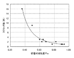
研磨材粒子の球形度Ψwが研磨面に与える影響について検証するため、各球形度の研磨材粒子(平均粒子径0.3μm)を用いた研磨フィルムを作製し次のように評価した。それぞれ10mm×10mm×5mmの石英ガラスブロックをワークとして、加工圧500g、研磨ストローク100mm、研磨回数50サイクルの条件にて石英ブロックを研磨し、微分干渉顕微鏡(カールツァイス社製Axio Plan、観察倍率×510.2)により研磨面上のスクラッチを評価した。ここでは研磨後の石英ガラスに発生しているスクラッチ本数が3本以下の場合、良好とし、4本以上の場合を不良とした。その結果、研磨材粒子の球形度Ψwが0.6以上ではスクラッチ発生頻度が少なく、高研磨面精度を得られることがわかった。反対に球形度Ψwが0.6を下回っている場合にはスクラッチ発生頻度が増加し、被研磨物にダメージが大きいことが確認された。評価結果を図2に示す。 In order to verify the influence of the sphericity Ψw of the abrasive particles on the polished surface, abrasive films using abrasive particles (average particle diameter of 0.3 μm) of each sphericity were prepared and evaluated as follows. Each 10 mm × 10 mm × 5 mm quartz glass block was used as a workpiece, the quartz block was polished under conditions of a processing pressure of 500 g, a polishing stroke of 100 mm, and a polishing frequency of 50 cycles, and a differential interference microscope (Axio Plan manufactured by Carl Zeiss, observation magnification × 510.2), scratches on the polished surface were evaluated. Here, when the number of scratches generated in the polished quartz glass was 3 or less, it was judged as good, and when it was 4 or more, it was judged as bad. As a result, it was found that when the sphericity Ψw of the abrasive particles is 0.6 or more, the frequency of occurrence of scratches is low and high polishing surface accuracy can be obtained. On the other hand, when the sphericity Ψw is less than 0.6, it was confirmed that the frequency of occurrence of scratches increased and the object to be polished was significantly damaged. The evaluation results are shown in FIG.
球形度Ψwが0.6以上の球状研磨材ではまた、通常の鋭利な角を有する不定形の研磨材と比較して、同一圧力下で砥粒の切り込み深さは同等であるが、球状砥粒に掛かる接触面積は増大する。その結果、一つの砥粒で除去される面積も増大するために、粉砕粉より研磨レートが高くなる。また、球状粒子の場合、広い接触面積で被研磨物を除去するために、鋭利な先端での引っかき除去の集合体である粉砕粉の場合に比較して、生成される研磨面粗さを良好に保つことができる。 A spherical abrasive having a sphericity Ψw of 0.6 or more also has an equivalent depth of cutting of the abrasive grains under the same pressure as compared to an irregular abrasive having a normal sharp angle. The contact area on the grains increases. As a result, since the area removed by one abrasive grain also increases, the polishing rate becomes higher than that of the pulverized powder. Also, in the case of spherical particles, in order to remove the object to be polished with a wide contact area, the generated polished surface roughness is better than in the case of pulverized powder that is an aggregate of scratch removal with a sharp tip. Can be kept in.
更に、充填率(バインダ樹脂中の研磨材体積濃度)が同等で比較的高い場合、球状粒子では、不定形粒子の集合体である粉砕粉に比較して、研磨材−研磨材間隙が比較的広くなるため、目詰まりの問題が発生しづらく、高い研磨レートを長時間にわたって維持することが可能である。特に、樹脂質の異物を除去する場合には目詰まりの問題は深刻であったが、球状粒子を用いた場合には、この問題も回避することができる。なお、上記充填率は、被研磨物に応じて最適値が決められる。 Further, when the filling rate (abrasive volume concentration in the binder resin) is equal and relatively high, the spherical particles have a relatively small abrasive-abrasive gap compared to the pulverized powder that is an aggregate of irregular shaped particles. Since it becomes wider, the problem of clogging hardly occurs, and a high polishing rate can be maintained for a long time. In particular, the clogging problem was serious when removing resinous foreign matter, but this problem can also be avoided when spherical particles are used. In addition, the said filling rate determines an optimal value according to a to-be-polished object.
球形度Ψwが0.6未満では、形状が不定形に近づくため、上述した接触面積や目詰まり回避特性が劣ってくる。なお、球形度Ψw1.0は真球であるために、これより大きな値になることはない。 When the sphericity Ψw is less than 0.6, the shape approaches an indeterminate shape, and the contact area and clogging avoidance characteristics described above are inferior. Since the sphericity Ψw1.0 is a true sphere, the value does not become larger than this.
本発明において、バインダ樹脂の、応力−ひずみ曲線から求められる破壊エネルギーの値は、0.1±0.05N/mの範囲である。なお、バインダ樹脂の破壊エネルギーとは、研磨材粒子を拘束・保持している状態の硬化又は乾燥したバインダ樹脂の破壊エネルギーを意味する。また、応力−ひずみ曲線は、JIS K7161に準拠した測定方法に従って以下のように求められる。 In the present invention, the value of the fracture energy obtained from the stress-strain curve of the binder resin is in the range of 0.1 ± 0.05 N / m. The breaking energy of the binder resin means the breaking energy of the cured or dried binder resin in a state where the abrasive particles are restrained and held. Moreover, a stress-strain curve is calculated | required as follows according to the measuring method based on JISK7161.
すなわち、一定の形状に作製された試験片(例えば100mm×10mm、厚さ0.02mm)を用い、ISO5893に準拠した試験機によって、試験片が破壊に至るまで、又は応力(荷重)もしくはひずみ(伸び)が規定値に達するまで、試験片を主縦軸に沿って一定速度で引っ張り、その間に試験片に掛かる荷重と伸びを測定する。試験中の荷重及びそれに対応する標線間距離及びクロスヘッド(測定用ロードセル)間距離の増加量を自動記録計を用いて応力−ひずみ曲線として記録する。得られた応力−ひずみ曲線の破断点に至るまでに掛かった荷重を引っ張り破壊強度、伸びを引張破壊伸度と呼ぶ。 That is, using a test piece (for example, 100 mm × 10 mm, thickness 0.02 mm) manufactured in a certain shape, until the test piece breaks or stress (load) or strain ( The test piece is pulled along the main longitudinal axis at a constant speed until the elongation reaches a specified value, and the load and elongation applied to the test piece during that time are measured. The load during the test and the corresponding increase in the distance between the marked lines and the distance between the crossheads (measurement load cells) are recorded as a stress-strain curve using an automatic recorder. The load applied up to the breaking point of the obtained stress-strain curve is called tensile fracture strength, and the elongation is called tensile fracture elongation.
引張破壊強度は次式によって算出される。
σ=F/A
ここで、σ=引張破壊強度(MPa)、F=破壊時の規定ひずみにおける荷重(N)、A=試験片の元の最小断面積(mm2)である。
The tensile fracture strength is calculated by the following formula.
σ = F / A
Here, σ = tensile fracture strength (MPa), F = load (N) at the specified strain at the time of fracture, and A = original minimum cross-sectional area (mm 2 ) of the test piece.
また、引張破壊伸度は次式によって算出される。
ε=(L−Lo)/Lo×100
ここで、ε=引張破壊伸度(%)、L=最大荷重時の標線間距離(mm)、Lo=元の標線間距離(mm)である。
Further, the tensile fracture elongation is calculated by the following formula.
ε = (L−Lo) / Lo × 100
Here, ε = tensile elongation at break (%), L = distance between marked lines at maximum load (mm), Lo = original distance between marked lines (mm).
破壊エネルギーGf(Fracture Energy Density)は、上述の試験方法によって求めた応力−ひずみ曲線の面積を表す(参考文献:On the transition from continuum nonlocal damage to quasi-brittle discrete crack models. C.Comi et al 2002 GIMC)。
破壊エネルギーは、応力−ひずみ曲線の破断点に至る面積を示すため、引張破壊強度及び引張破壊伸度共に大きな材料程、大きな値になることから、強靭であることが示されている。
Fracture Energy Density (Gf) represents the area of the stress-strain curve obtained by the above test method (Reference: On the transition from continuum nonlocal damage to quasi-brittle discrete crack models. C. Comi et al 2002 GIMC).
Since the fracture energy indicates the area to the fracture point of the stress-strain curve, the larger the tensile fracture strength and the tensile fracture elongation, the greater the value, indicating that the fracture energy is tough.
破壊エネルギーが上記範囲内のバインダ樹脂を用いると、研磨力と研磨面精度の両特性のバランスをとることができる。破壊エネルギーの値が0.05N/m以下のバインダ樹脂を用いると、カラーフィルター表面に対してマイルドに加工が進行するために、研磨面精度は優れているが所望の研磨力を得ることができない。一方、破壊エネルギーの値が0.15N/mを超える硬質なバインダ樹脂を用いた場合には、高い研磨力は得られるが、研磨面に与えるダメージが大きく液晶カラーフィルターの修正には適さない。このように破壊エネルギーの値が0.10±0.05N/mの範囲のバインダ樹脂を用いることが、液晶カラーフィルター修正用研磨フィルムには重要な因子となっている。 When a binder resin having a fracture energy within the above range is used, it is possible to balance both characteristics of polishing power and polished surface accuracy. When a binder resin having a fracture energy value of 0.05 N / m or less is used, processing progresses mildly with respect to the color filter surface, so that the polishing surface accuracy is excellent but a desired polishing force cannot be obtained. . On the other hand, when a hard binder resin having a fracture energy value of more than 0.15 N / m is used, a high polishing power can be obtained, but damage to the polished surface is great and it is not suitable for correcting a liquid crystal color filter. Thus, the use of a binder resin having a fracture energy value in the range of 0.10 ± 0.05 N / m is an important factor for a polishing film for correcting a liquid crystal color filter.
破壊エネルギーが上記範囲内のバインダ樹脂を用いると、研磨力と研磨面精度の両特性のバランスをとることができる。破壊エネルギーの値が0.05N/m以下のバインダ樹脂を用いると、カラーフィルター表面に対してマイルドに加工が進行するために、研磨面精度は優れているが所望の研磨力を得ることができない。一方、破壊エネルギーの値が0.15N/mを超える硬質なバインダ樹脂を用いた場合には、高い研磨力は得られるが、研磨面に与えるダメージが大きく液晶カラーフィルターの修正には適さない。このように破壊エネルギーの値が0.10±0.05N/mの範囲のバインダ樹脂を用いることが、液晶カラーフィルター修正用研磨フィルムには重要な因子となっている。 When a binder resin having a fracture energy within the above range is used, it is possible to balance both characteristics of polishing power and polished surface accuracy. When a binder resin having a fracture energy value of 0.05 N / m or less is used, processing progresses mildly with respect to the color filter surface, so that the polishing surface accuracy is excellent but a desired polishing force cannot be obtained. . On the other hand, when a hard binder resin having a fracture energy value of more than 0.15 N / m is used, a high polishing power can be obtained, but damage to the polished surface is great and it is not suitable for correcting a liquid crystal color filter. Thus, the use of a binder resin having a fracture energy value in the range of 0.10 ± 0.05 N / m is an important factor for a polishing film for correcting a liquid crystal color filter.
以上の物性を有するバインダ樹脂としては、ポリウレタン樹脂が好適である。特に、本発明に用いるバインダ樹脂として、カルボキシル基含有ポリウレタン樹脂をイソシアネート化合物により架橋させた系が望ましい。一般にアルミナ粒子は、酸−塩基の分類からは塩基性粒子であるために、バインダ樹脂にカルボキシル基が官能基として存在するポリウレタン樹脂を用いることによって、アルミナ研磨材粒子表面とバインダ樹脂の官能基が相互作用し、分散性を改善し、その結果、粒子の保持力が向上する。すなわち、塩基性顔料であるアルミナ研磨材の表面に対し、酸性官能基を有するバインダ樹脂が吸着しやすいため、粒子表面をバインダ樹脂により完全に濡らすことができ、これにより分散性が向上し、なおかつ粒子表面がバインダ樹脂によって被覆されているため、結果として粒子の保持力が高まる。そのため、液晶カラーフィルターの研磨中に、研磨材粒子のバインダ樹脂からの脱落などによるスクラッチの発生を抑えることが可能となる。なお、バインダ樹脂は単独もしくは二種類以上任意の割合で使用される。 As the binder resin having the above physical properties, a polyurethane resin is suitable. In particular, the binder resin used in the present invention is preferably a system in which a carboxyl group-containing polyurethane resin is crosslinked with an isocyanate compound. In general, alumina particles are basic particles from the classification of acid-base. Therefore, by using a polyurethane resin in which a carboxyl group is present as a functional group in the binder resin, the alumina abrasive particle surface and the functional group of the binder resin are changed. Interact and improve dispersibility, resulting in improved retention of particles. That is, since the binder resin having an acidic functional group is easily adsorbed to the surface of the alumina abrasive that is a basic pigment, the particle surface can be completely wetted with the binder resin, thereby improving dispersibility, and Since the particle surface is coated with the binder resin, the retention force of the particles is increased as a result. Therefore, during the polishing of the liquid crystal color filter, it is possible to suppress the occurrence of scratches due to the removal of the abrasive particles from the binder resin. In addition, binder resin is used individually or in 2 or more types in arbitrary ratios.
以下、本発明の好適な実施形態について説明する。 Hereinafter, preferred embodiments of the present invention will be described.
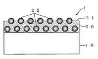
図1は、本発明に係る液晶カラーフィルター用研磨フィルム1の概略断面図である。研磨フィルム1は、基材フィルム10と、基材フィルム10上に固着・形成した研磨層20とからなる。研磨層20は、バインダ樹脂21と、バインダ樹脂21によって固定化された多数の研磨材粒子22とを含む。基材フィルム10としては、厚さ25ミクロンのPETを用いた。バインダ樹脂21としては、カルボキシル基含有ポリウレタン樹脂を用いた。また、研磨層20をなしているバインダ樹脂21の、JIS K7161に準拠した測定方法に従う応力−ひずみ曲線から求められる破壊エネルギーの値を、0.1±0.05N/mの範囲となるように調製した。更に、研磨材粒子22としては、平均球形度Ψwが0.6以上でかつ平均粒子径が0.3μmのαアルミナを用いた。
FIG. 1 is a schematic cross-sectional view of a
研磨層20は、バインダ樹脂21及び硬化剤を溶媒で均一に溶解すると共に該溶媒(樹脂液)中に研磨材粒子22を分散させてなる塗工液を、基材フィルム10上に塗布し、これを乾燥又は硬化処理することにより製造した。研磨材粒子22は、必要量を秤量し、混合して、サンドミルなどの分散機で樹脂液中に均一に分散される。基材上への塗布手段としては、例えば、ワイヤーバーコーター、グラビアコーター、リバースコーター、ナイフコーター、ノズル、ダイコーターなどを使用することができる。
The polishing layer 20 is a solution in which the binder resin 21 and the curing agent are uniformly dissolved with a solvent, and a coating liquid in which abrasive particles 22 are dispersed in the solvent (resin liquid) is applied onto the
硬化剤としては、ポリイソシアネートを用いることができ、具体例として、ヘキサメチレンジイソシアネート、トリレンジイソシアネート、キシリレンジイソシアネート、イソホロンジイソシアネート、ナフチレンジイソシアネート等を挙げることができる。これらの硬化剤は単独もしくは二種類以上任意の割合で使用される。 As the curing agent, polyisocyanate can be used, and specific examples include hexamethylene diisocyanate, tolylene diisocyanate, xylylene diisocyanate, isophorone diisocyanate, naphthylene diisocyanate, and the like. These curing agents are used alone or in any proportion of two or more.
研磨層20を形成するための塗工液に使用される溶媒としては、アセトン、メチルエチルケトン、メチルイソブチルケトン、シクロヘキサノン、イソホロン、酢酸エチル酢酸ブチル、テトラヒドロフラン、トルエン、キシレン、エタノール、イソプロパノール等を用いることができるが、これらに限定されるものではない。これらの有機溶剤は、バインダ樹脂21及び硬化剤を均一溶解でき、また、研磨材粒子22を安定して分散させることができる。更に、該溶媒は、塗布後、完全乾燥除去されるように、単独もしくは二種類以上任意の割合で使用される。 As the solvent used in the coating liquid for forming the polishing layer 20, acetone, methyl ethyl ketone, methyl isobutyl ketone, cyclohexanone, isophorone, ethyl butyl acetate, tetrahydrofuran, toluene, xylene, ethanol, isopropanol, etc. may be used. However, it is not limited to these. These organic solvents can uniformly dissolve the binder resin 21 and the curing agent, and can stably disperse the abrasive particles 22. Further, the solvent is used alone or in an arbitrary ratio of two or more so that it is completely dried and removed after coating.
なお、上記塗工液において、必要に応じて他の界面活性剤やカップリング剤などを使用することができる。 In addition, in the said coating liquid, other surfactant, a coupling agent, etc. can be used as needed.
次に、以上の液晶カラーフィルター用研磨フィルム1の具体例である本発明の実施例1及び2を比較例1から5と比較して、本発明の効果等を説明する。
Next, Examples 1 and 2 of the present invention, which are specific examples of the above-described liquid crystal color
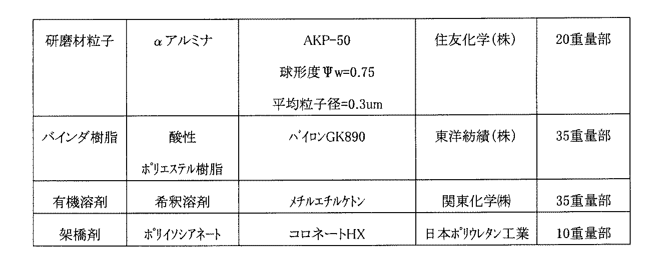
実施例1の研磨フィルムを次のようにして得た。有機溶剤としてのメチルエチルケトンと、カルボキシル基含有バインダ樹脂としてのポリウレタン系樹脂(商品名「ダイフェラミンMAU5022」:大日精化(株)製)とを用いて33wt%の樹脂液を作製した。この樹脂液に対し、研磨材粒子として平均球形度Ψw=0.75、平均粒子径0.3ミクロンのαアルミナ粒子(商品名「AKP−50」:住友化学(株)製)を、サンドミルで均一に混合・分散した後、イソシアネート架橋剤(硬化剤)(商品名「コロネートHX」:日本ポリウレタン工業(株)製)を撹拌しながら加え、その後、濾過精度5μmのフィルターリングを施して塗工液を作製した。この塗工液の組成を表1に示す。この塗工液を、ナイフコーターにより、基材としての、易接着処理を施した厚み25μmのポリエチレンテレフタレートフィルム(商品名「SG−2」:帝人(株)製)上に塗布した。コーターの乾燥炉温度は120℃に設定され、塗布後、24時間室温放置し、次いで40℃にて48時間エージングをし、当該研磨フィルムを得た。 The abrasive film of Example 1 was obtained as follows. A 33 wt% resin solution was prepared using methyl ethyl ketone as an organic solvent and a polyurethane-based resin (trade name “Dyferamin MAU5022” manufactured by Dainichi Seika Co., Ltd.) as a carboxyl group-containing binder resin. For this resin liquid, α-alumina particles (trade name “AKP-50” manufactured by Sumitomo Chemical Co., Ltd.) having an average sphericity of Ψw = 0.75 and an average particle diameter of 0.3 microns were used as abrasive particles with a sand mill. After mixing and dispersing uniformly, an isocyanate cross-linking agent (curing agent) (trade name “Coronate HX”: manufactured by Nippon Polyurethane Industry Co., Ltd.) is added with stirring, followed by coating with a filtering accuracy of 5 μm. A liquid was prepared. The composition of this coating solution is shown in Table 1. This coating solution was applied with a knife coater onto a polyethylene terephthalate film (trade name “SG-2” manufactured by Teijin Ltd.) having a thickness of 25 μm and subjected to easy adhesion treatment. The drying oven temperature of the coater was set to 120 ° C., and after coating, left at room temperature for 24 hours, and then aged at 40 ° C. for 48 hours to obtain the abrasive film.
実施例2の研磨フィルム(その塗工液の組成を表2に示す。)は、バインダ樹脂のみをスルフォベタイン基含有ポリウレタン(商品名「タケラックE−780」:三井武田ケミカル(株)製)に変更して、実施例1と同様に作製したものである。 The abrasive film of Example 2 (the composition of the coating solution is shown in Table 2) is a polyurethane resin containing sulfobetaine group (trade name “Takelac E-780” manufactured by Mitsui Takeda Chemical Co., Ltd.) In this way, it was fabricated in the same manner as in Example 1.
実施例1及び2に対する比較例として、比較例1の研磨フィルムは、実施例1の研磨フィルムに対し、研磨材粒子を、平均球形度Ψw=0.5及び平均粒子径0.3ミクロンの粉砕アルミナ粒子(商品名「WA20000」:(株)フジミインコーポレーテッド製)に、比較例2の研磨フィルムは、平均球形度Ψw=0.36及び平均粒子径0.2ミクロンのシリコーンカーバイト研磨材(商品名「GC30000」:(株)フジミインコーポレーテッド製)にそれぞれ変更して調製したものである。比較例1及び2の塗工液の組成を表3及び4に示す。 As a comparative example for Examples 1 and 2, the abrasive film of Comparative Example 1 was crushed with abrasive particles having an average sphericity of Ψw = 0.5 and an average particle diameter of 0.3 microns with respect to the abrasive film of Example 1. Alumina particles (trade name “WA20000”: manufactured by Fujimi Incorporated), the abrasive film of Comparative Example 2 is a silicone carbide abrasive material having an average sphericity Ψw = 0.36 and an average particle diameter of 0.2 microns ( Product name “GC30000”: manufactured by Fujimi Incorporated). Tables 3 and 4 show the compositions of the coating liquids of Comparative Examples 1 and 2.
また、比較例3の研磨フィルムは、実施例1の研磨フィルムに対し、バインダ樹脂を無極性のもの(商品名「MAU9022」:大日精化製)に、比較例4の研磨フィルムは、バインダ樹脂を塩基性のものに(商品名「MAU4308」:大日精化製)にそれぞれ変更して調製したものである。更に、比較例5の研磨フィルムは、実施例1の研磨フィルムに対し、バインダ樹脂を、カルボキシル基を含有するポリエステル樹脂(商品名「バイロンGK890」:東洋紡績(株)製)に変更して調製したものである。比較例3〜5の塗工液の組成を表5〜7に示す。 The polishing film of Comparative Example 3 is a non-polar binder resin (trade name “MAU9022” manufactured by Dainichi Seika) with respect to the polishing film of Example 1, and the polishing film of Comparative Example 4 is a binder resin. Were changed to basic ones (trade name “MAU4308” manufactured by Dainichi Seika). Furthermore, the polishing film of Comparative Example 5 was prepared by changing the binder resin to a polyester resin containing a carboxyl group (trade name “Byron GK890” manufactured by Toyobo Co., Ltd.) with respect to the polishing film of Example 1. It is a thing. The compositions of the coating liquids of Comparative Examples 3 to 5 are shown in Tables 5 to 7.
以上の実施例及び比較例の研磨フィルムについて、JIS K7161に準拠した測定方法に従う応力−ひずみ曲線から求められる破壊エネルギーの値を、オリエンテック社製引張試験機にて測定した。測定条件は、クロスヘッド速度200.0mm/min、試料幅10.0mm、厚さ0.02mm、初期試料長さ50.0mmとし、各試料とも5回応力−ひずみ曲線を測定し、その平均値を用いた。各試料の破壊エネルギーの測定値を表8に示す。 About the abrasive film of the above Example and the comparative example, the value of the fracture energy calculated | required from the stress-strain curve according to the measuring method based on JISK7161 was measured with the orientec company made tensile tester. The measurement conditions were a crosshead speed of 200.0 mm / min, a sample width of 10.0 mm, a thickness of 0.02 mm, and an initial sample length of 50.0 mm. Was used. Table 8 shows the measured values of the fracture energy of each sample.
研磨特性は、実際の液晶カラーフィルター上に存在し得る金属性異物、ガラスカレット、樹脂の未溶解物からなる各種硬度の異物を想定し、それぞれ、10mm×10mm×5mmのセンダストブロック、石英ガラスブロック、ポリイミドブロックを作製し、加工圧500g、研磨ストローク100mm、研磨回数50サイクルの条件にて各ブロックをダミー研磨(ダミー研磨用のオリジナル機械を作製して使用)し、そのときの研磨力を求めた。 The polishing characteristics are assumed to be metallic foreign matter, glass cullet, and foreign matter of various hardness consisting of undissolved resin, which can be present on the actual liquid crystal color filter, respectively, 10mm x 10mm x 5mm sendust block, quartz glass block A polyimide block is prepared, and each block is dummy-polished (using an original machine for dummy polishing and used) under conditions of a processing pressure of 500 g, a polishing stroke of 100 mm, and a polishing frequency of 50 cycles, and the polishing power at that time is obtained. It was.
研磨力判定は、硬度の異なるそれぞれのブロックの研磨量がほぼ同等なものを良好とし、硬度差による研磨量のばらつきが大きいものを不良とした。 In the judgment of the polishing force, a block having almost the same polishing amount for each block having different hardness was evaluated as good, and a block having a large variation in polishing amount due to a difference in hardness was determined as defective.
研磨面(上記各ブロックで実施したダミー研磨の研磨面)の評価は、微分干渉顕微鏡(カールツァイス社製Axio Plan、観察倍率×510.2)により、各ブロックの10mm×10mmの研磨面全域におけるスクラッチを次のように評価した。すなわち、スクラッチの発生がないものを◎、観察エリア内に1〜3本のスクラッチが発生しているものを○、4本以上のスクラッチが発生するものを×とした。 Evaluation of the polishing surface (polishing surface of the dummy polishing performed in each of the above blocks) was performed over the entire 10 mm × 10 mm polishing surface of each block using a differential interference microscope (Axio Plan manufactured by Carl Zeiss, observation magnification × 510.2). The scratch was evaluated as follows. That is, ◎ indicates that no scratch is generated, ◯ indicates that 1 to 3 scratches are generated in the observation area, and × indicates that 4 or more scratches are generated.
以上の研磨力及び研磨面評価の結果を表9に示す。 Table 9 shows the results of the above polishing force and polished surface evaluation.
また、実際の液晶カラーフィルターの異物(突起)除去実験も併せて行った。この実験では、液晶カラーフィルター上に存在する各突起の高さを予め測定し、その突起を、カラーフィルター研磨装置で研磨し、研磨後の突起高さが5ミクロン以下になるまでの研磨回数を求め、そのときの加工面状態を上記スクラッチ評価とほぼ同様に評価した。この際、上記研磨回数が1回でかつ加工面状態が◎もしくは○のものを良好と判定し、研磨回数が1回でも加工面状態が×であるか、又は、加工面状態が◎もしくは○でも研磨回数が2回以上の場合、不良(研磨力不足/研磨面悪)と判定した。かかる実験結果を表10に示す。 In addition, an actual liquid crystal color filter foreign matter (projection) removal experiment was also performed. In this experiment, the height of each protrusion existing on the liquid crystal color filter is measured in advance, the protrusion is polished with a color filter polishing apparatus, and the number of times of polishing until the protrusion height after polishing becomes 5 microns or less is measured. The processed surface state at that time was evaluated in substantially the same manner as the scratch evaluation. At this time, it is determined that the number of polishing times is 1 and the processed surface state is ◎ or ◯, and the processed surface state is x even when the polishing number is 1, or the processed surface state is ◎ or ○. However, when the number of times of polishing was 2 times or more, it was judged as defective (insufficient polishing power / poor polishing surface). The experimental results are shown in Table 10.
以上の試験・実験結果から、研磨材粒子の平均球形度Ψwが0.6〜1であり、バインダ樹脂の応力−ひずみ曲線から求められる破壊エネルギーの値が0.1±0.05N/mの範囲であり、バインダ樹脂としてカルボキシル基含有ポリウレタンを用いた、実施例1及び2のような液晶カラーフィルター用研磨フィルムでは、硬度の異なる複数の異物に対しても短時間で所望の研磨力が得られ、なおかつ研磨面状態も良好であることが確認された。その一方、比較例1〜3のように破壊エネルギーの値が上記範囲にあっても、研磨材粒子の球形度が0.6未満の場合、あるいは、比較例5のように酸性バインダを用いても、破壊エネルギーの値が上記範囲外である場合には、研磨力不足や研磨面不良が発生し、液晶カラーフィルターの異物研磨には適さないことも確認された。 From the above test and experimental results, the average sphericity Ψw of the abrasive particles is 0.6 to 1, and the value of the fracture energy obtained from the stress-strain curve of the binder resin is 0.1 ± 0.05 N / m. In the polishing film for liquid crystal color filters as in Examples 1 and 2 using a carboxyl group-containing polyurethane as a binder resin, a desired polishing force can be obtained in a short time even for a plurality of foreign matters having different hardnesses. In addition, it was confirmed that the polished surface condition was also good. On the other hand, even if the value of the fracture energy is in the above range as in Comparative Examples 1 to 3, when the sphericity of the abrasive particles is less than 0.6, or using an acidic binder as in Comparative Example 5 However, it was also confirmed that when the value of the breaking energy is outside the above range, the polishing power is insufficient or the polishing surface is defective, which is not suitable for the foreign matter polishing of the liquid crystal color filter.
以上のように、本発明に係る液晶カラーフィルター用研磨フィルムでは、硬度の異なる異物等であっても短時間で良好な研磨力及び仕上げ面精度を得ることができるため、液晶カラーフィルター製造工程で該フィルター上に発生する様々な硬度を有する異物や突起を安定して高研磨レートで除去でき、なおかつ高い研磨面品位を得ることができる。 As described above, in the liquid crystal color filter polishing film according to the present invention, it is possible to obtain good polishing power and finished surface accuracy in a short time even for foreign matters having different hardnesses. Foreign matters and protrusions having various hardnesses generated on the filter can be stably removed at a high polishing rate, and a high polished surface quality can be obtained.
1 液晶カラーフィルター用研磨フィルム
10 基材フィルム
20 研磨層
21 バインダ樹脂
22 研磨材粒子
DESCRIPTION OF
Claims (4)
研磨材粒子の平均球形度Ψwが0.6〜1.0であり、
バインダ樹脂の、応力−ひずみ曲線から求められる破壊エネルギーの値が0.1±0.05N/mの範囲であることを特徴とする液晶カラーフィルター用研磨フィルム。 In the polishing film for liquid crystal color filters in which the abrasive particles are fixed with a binder resin on the substrate,
The average sphericity Ψw of the abrasive particles is 0.6 to 1.0,
A polishing film for a liquid crystal color filter, wherein a binder resin has a fracture energy value determined from a stress-strain curve in a range of 0.1 ± 0.05 N / m.
Priority Applications (1)
| Application Number | Priority Date | Filing Date | Title |
|---|---|---|---|
| JP2005007851A JP2006192540A (en) | 2005-01-14 | 2005-01-14 | Polishing film for liquid crystal color filter |
Applications Claiming Priority (1)
| Application Number | Priority Date | Filing Date | Title |
|---|---|---|---|
| JP2005007851A JP2006192540A (en) | 2005-01-14 | 2005-01-14 | Polishing film for liquid crystal color filter |
Publications (1)
| Publication Number | Publication Date |
|---|---|
| JP2006192540A true JP2006192540A (en) | 2006-07-27 |
Family
ID=36798992
Family Applications (1)
| Application Number | Title | Priority Date | Filing Date |
|---|---|---|---|
| JP2005007851A Pending JP2006192540A (en) | 2005-01-14 | 2005-01-14 | Polishing film for liquid crystal color filter |
Country Status (1)
| Country | Link |
|---|---|
| JP (1) | JP2006192540A (en) |
Cited By (45)
| Publication number | Priority date | Publication date | Assignee | Title |
|---|---|---|---|---|
| WO2010077518A1 (en) * | 2008-12-17 | 2010-07-08 | 3M Innovative Properties Company | Shaped abrasive particles with an opening |
| JP2010274341A (en) * | 2009-05-26 | 2010-12-09 | Shin Etsu Handotai Co Ltd | Method of discriminating whetstone |
| US8123828B2 (en) | 2007-12-27 | 2012-02-28 | 3M Innovative Properties Company | Method of making abrasive shards, shaped abrasive particles with an opening, or dish-shaped abrasive particles |
| US8142891B2 (en) | 2008-12-17 | 2012-03-27 | 3M Innovative Properties Company | Dish-shaped abrasive particles with a recessed surface |
| US8142531B2 (en) | 2008-12-17 | 2012-03-27 | 3M Innovative Properties Company | Shaped abrasive particles with a sloping sidewall |
| US8753742B2 (en) | 2012-01-10 | 2014-06-17 | Saint-Gobain Ceramics & Plastics, Inc. | Abrasive particles having complex shapes and methods of forming same |
| US8753558B2 (en) | 2011-12-30 | 2014-06-17 | Saint-Gobain Ceramics & Plastics, Inc. | Forming shaped abrasive particles |
| US8758461B2 (en) | 2010-12-31 | 2014-06-24 | Saint-Gobain Ceramics & Plastics, Inc. | Abrasive particles having particular shapes and methods of forming such particles |
| US8764865B2 (en) | 2008-12-17 | 2014-07-01 | 3M Innovative Properties Company | Shaped abrasive particles with grooves |
| US8764863B2 (en) | 2011-12-30 | 2014-07-01 | Saint-Gobain Ceramics & Plastics, Inc. | Composite shaped abrasive particles and method of forming same |
| US8840694B2 (en) | 2011-06-30 | 2014-09-23 | Saint-Gobain Ceramics & Plastics, Inc. | Liquid phase sintered silicon carbide abrasive particles |
| US8840696B2 (en) | 2012-01-10 | 2014-09-23 | Saint-Gobain Ceramics & Plastics, Inc. | Abrasive particles having particular shapes and methods of forming such particles |
| US8840695B2 (en) | 2011-12-30 | 2014-09-23 | Saint-Gobain Ceramics & Plastics, Inc. | Shaped abrasive particle and method of forming same |
| US8986409B2 (en) | 2011-06-30 | 2015-03-24 | Saint-Gobain Ceramics & Plastics, Inc. | Abrasive articles including abrasive particles of silicon nitride |
| US9074119B2 (en) | 2012-12-31 | 2015-07-07 | Saint-Gobain Ceramics & Plastics, Inc. | Particulate materials and methods of forming same |
| US9150765B2 (en) | 2009-12-22 | 2015-10-06 | 3M Innovative Properties Company | Transfer assisted screen printing method of making shaped abrasive particles and the resulting shaped abrasive particles |
| US9200187B2 (en) | 2012-05-23 | 2015-12-01 | Saint-Gobain Ceramics & Plastics, Inc. | Shaped abrasive particles and methods of forming same |
| US9242346B2 (en) | 2012-03-30 | 2016-01-26 | Saint-Gobain Abrasives, Inc. | Abrasive products having fibrillated fibers |
| CN105773458A (en) * | 2016-05-16 | 2016-07-20 | 衢州学院 | High-solid-content nano spherical silicon dioxide polishing film and preparing method thereof |
| US9440332B2 (en) | 2012-10-15 | 2016-09-13 | Saint-Gobain Abrasives, Inc. | Abrasive particles having particular shapes and methods of forming such particles |
| US9457453B2 (en) | 2013-03-29 | 2016-10-04 | Saint-Gobain Abrasives, Inc./Saint-Gobain Abrasifs | Abrasive particles having particular shapes and methods of forming such particles |
| US9517546B2 (en) | 2011-09-26 | 2016-12-13 | Saint-Gobain Ceramics & Plastics, Inc. | Abrasive articles including abrasive particulate materials, coated abrasives using the abrasive particulate materials and methods of forming |
| US9566689B2 (en) | 2013-12-31 | 2017-02-14 | Saint-Gobain Abrasives, Inc. | Abrasive article including shaped abrasive particles |
| US9604346B2 (en) | 2013-06-28 | 2017-03-28 | Saint-Gobain Cermaics & Plastics, Inc. | Abrasive article including shaped abrasive particles |
| US9676981B2 (en) | 2014-12-24 | 2017-06-13 | Saint-Gobain Ceramics & Plastics, Inc. | Shaped abrasive particle fractions and method of forming same |
| US9707529B2 (en) | 2014-12-23 | 2017-07-18 | Saint-Gobain Ceramics & Plastics, Inc. | Composite shaped abrasive particles and method of forming same |
| US9771507B2 (en) | 2014-01-31 | 2017-09-26 | Saint-Gobain Ceramics & Plastics, Inc. | Shaped abrasive particle including dopant material and method of forming same |
| US9783718B2 (en) | 2013-09-30 | 2017-10-10 | Saint-Gobain Ceramics & Plastics, Inc. | Shaped abrasive particles and methods of forming same |
| US9803119B2 (en) | 2014-04-14 | 2017-10-31 | Saint-Gobain Ceramics & Plastics, Inc. | Abrasive article including shaped abrasive particles |
| US9902045B2 (en) | 2014-05-30 | 2018-02-27 | Saint-Gobain Abrasives, Inc. | Method of using an abrasive article including shaped abrasive particles |
| US9914864B2 (en) | 2014-12-23 | 2018-03-13 | Saint-Gobain Ceramics & Plastics, Inc. | Shaped abrasive particles and method of forming same |
| US9938440B2 (en) | 2015-03-31 | 2018-04-10 | Saint-Gobain Abrasives, Inc./Saint-Gobain Abrasifs | Fixed abrasive articles and methods of forming same |
| US10106714B2 (en) | 2012-06-29 | 2018-10-23 | Saint-Gobain Ceramics & Plastics, Inc. | Abrasive particles having particular shapes and methods of forming such particles |
| US10137556B2 (en) | 2009-06-22 | 2018-11-27 | 3M Innovative Properties Company | Shaped abrasive particles with low roundness factor |
| US10196551B2 (en) | 2015-03-31 | 2019-02-05 | Saint-Gobain Abrasives, Inc. | Fixed abrasive articles and methods of forming same |
| US10557067B2 (en) | 2014-04-14 | 2020-02-11 | Saint-Gobain Ceramics & Plastics, Inc. | Abrasive article including shaped abrasive particles |
| US10563105B2 (en) | 2017-01-31 | 2020-02-18 | Saint-Gobain Ceramics & Plastics, Inc. | Abrasive article including shaped abrasive particles |
| US10711171B2 (en) | 2015-06-11 | 2020-07-14 | Saint-Gobain Ceramics & Plastics, Inc. | Abrasive article including shaped abrasive particles |
| US10759024B2 (en) | 2017-01-31 | 2020-09-01 | Saint-Gobain Ceramics & Plastics, Inc. | Abrasive article including shaped abrasive particles |
| US10865148B2 (en) | 2017-06-21 | 2020-12-15 | Saint-Gobain Ceramics & Plastics, Inc. | Particulate materials and methods of forming same |
| US11230653B2 (en) | 2016-09-29 | 2022-01-25 | Saint-Gobain Abrasives, Inc. | Fixed abrasive articles and methods of forming same |
| CN114952643A (en) * | 2022-05-25 | 2022-08-30 | 成都贝瑞光电科技股份有限公司 | Manufacturing method of fixed abrasive polishing asphalt disc |
| US11718774B2 (en) | 2016-05-10 | 2023-08-08 | Saint-Gobain Ceramics & Plastics, Inc. | Abrasive particles and methods of forming same |
| US11926019B2 (en) | 2019-12-27 | 2024-03-12 | Saint-Gobain Ceramics & Plastics, Inc. | Abrasive articles and methods of forming same |
| US11959009B2 (en) | 2016-05-10 | 2024-04-16 | Saint-Gobain Ceramics & Plastics, Inc. | Abrasive particles and methods of forming same |
Citations (6)
| Publication number | Priority date | Publication date | Assignee | Title |
|---|---|---|---|---|
| JPH0825205A (en) * | 1994-07-20 | 1996-01-30 | Fuji Photo Film Co Ltd | Polishing method |
| JPH08291356A (en) * | 1995-04-20 | 1996-11-05 | Sumitomo Electric Ind Ltd | Cbn sintered compact and its manufacture |
| JP2001071273A (en) * | 1999-09-01 | 2001-03-21 | Hitachi Maxell Ltd | Abrasive sheet |
| JP2004268152A (en) * | 2003-03-05 | 2004-09-30 | Tokyo Magnetic Printing Co Ltd | Polishing film |
| JP2004322253A (en) * | 2003-04-24 | 2004-11-18 | Admatechs Co Ltd | Fixed abrasive grain polishing material |
| JP2004330345A (en) * | 2003-05-07 | 2004-11-25 | Hitachi Zosen Corp | Method and apparatus for grinding flake workpiece |
-
2005
- 2005-01-14 JP JP2005007851A patent/JP2006192540A/en active Pending
Patent Citations (6)
| Publication number | Priority date | Publication date | Assignee | Title |
|---|---|---|---|---|
| JPH0825205A (en) * | 1994-07-20 | 1996-01-30 | Fuji Photo Film Co Ltd | Polishing method |
| JPH08291356A (en) * | 1995-04-20 | 1996-11-05 | Sumitomo Electric Ind Ltd | Cbn sintered compact and its manufacture |
| JP2001071273A (en) * | 1999-09-01 | 2001-03-21 | Hitachi Maxell Ltd | Abrasive sheet |
| JP2004268152A (en) * | 2003-03-05 | 2004-09-30 | Tokyo Magnetic Printing Co Ltd | Polishing film |
| JP2004322253A (en) * | 2003-04-24 | 2004-11-18 | Admatechs Co Ltd | Fixed abrasive grain polishing material |
| JP2004330345A (en) * | 2003-05-07 | 2004-11-25 | Hitachi Zosen Corp | Method and apparatus for grinding flake workpiece |
Cited By (94)
| Publication number | Priority date | Publication date | Assignee | Title |
|---|---|---|---|---|
| US8123828B2 (en) | 2007-12-27 | 2012-02-28 | 3M Innovative Properties Company | Method of making abrasive shards, shaped abrasive particles with an opening, or dish-shaped abrasive particles |
| US9938439B2 (en) | 2008-12-17 | 2018-04-10 | 3M Innovative Properties Company | Production tool to make abrasive particles with grooves |
| US9890309B2 (en) | 2008-12-17 | 2018-02-13 | 3M Innovative Properties Company | Abrasive article with shaped abrasive particles with grooves |
| US8764865B2 (en) | 2008-12-17 | 2014-07-01 | 3M Innovative Properties Company | Shaped abrasive particles with grooves |
| US8142891B2 (en) | 2008-12-17 | 2012-03-27 | 3M Innovative Properties Company | Dish-shaped abrasive particles with a recessed surface |
| US8142532B2 (en) | 2008-12-17 | 2012-03-27 | 3M Innovative Properties Company | Shaped abrasive particles with an opening |
| US8142531B2 (en) | 2008-12-17 | 2012-03-27 | 3M Innovative Properties Company | Shaped abrasive particles with a sloping sidewall |
| JP2012512047A (en) * | 2008-12-17 | 2012-05-31 | スリーエム イノベイティブ プロパティズ カンパニー | Molded abrasive particles having openings |
| CN102281993B (en) * | 2008-12-17 | 2014-01-29 | 3M创新有限公司 | Shaped abrasive particles with an opening |
| WO2010077518A1 (en) * | 2008-12-17 | 2010-07-08 | 3M Innovative Properties Company | Shaped abrasive particles with an opening |
| KR101800900B1 (en) | 2008-12-17 | 2017-11-23 | 쓰리엠 이노베이티브 프로퍼티즈 컴파니 | Shaped abrasive particles with an opening |
| US11767454B2 (en) | 2008-12-17 | 2023-09-26 | 3M Innovative Properties Company | Production tool to make abrasive particles with grooves |
| CN102281993A (en) * | 2008-12-17 | 2011-12-14 | 3M创新有限公司 | Shaped abrasive particles with an opening |
| US10987780B2 (en) | 2008-12-17 | 2021-04-27 | 3M Innovative Properties Company | Shaped abrasive particles with a sloping sidewall |
| JP2010274341A (en) * | 2009-05-26 | 2010-12-09 | Shin Etsu Handotai Co Ltd | Method of discriminating whetstone |
| US10137556B2 (en) | 2009-06-22 | 2018-11-27 | 3M Innovative Properties Company | Shaped abrasive particles with low roundness factor |
| US9150765B2 (en) | 2009-12-22 | 2015-10-06 | 3M Innovative Properties Company | Transfer assisted screen printing method of making shaped abrasive particles and the resulting shaped abrasive particles |
| US9017439B2 (en) | 2010-12-31 | 2015-04-28 | Saint-Gobain Ceramics & Plastics, Inc. | Abrasive particles having particular shapes and methods of forming such particles |
| US8758461B2 (en) | 2010-12-31 | 2014-06-24 | Saint-Gobain Ceramics & Plastics, Inc. | Abrasive particles having particular shapes and methods of forming such particles |
| US9303196B2 (en) | 2011-06-30 | 2016-04-05 | Saint-Gobain Ceramics & Plastics, Inc. | Liquid phase sintered silicon carbide abrasive particles |
| US8840694B2 (en) | 2011-06-30 | 2014-09-23 | Saint-Gobain Ceramics & Plastics, Inc. | Liquid phase sintered silicon carbide abrasive particles |
| US8986409B2 (en) | 2011-06-30 | 2015-03-24 | Saint-Gobain Ceramics & Plastics, Inc. | Abrasive articles including abrasive particles of silicon nitride |
| US9598620B2 (en) | 2011-06-30 | 2017-03-21 | Saint-Gobain Ceramics & Plastics, Inc. | Abrasive articles including abrasive particles of silicon nitride |
| US9517546B2 (en) | 2011-09-26 | 2016-12-13 | Saint-Gobain Ceramics & Plastics, Inc. | Abrasive articles including abrasive particulate materials, coated abrasives using the abrasive particulate materials and methods of forming |
| US11453811B2 (en) | 2011-12-30 | 2022-09-27 | Saint-Gobain Ceramics & Plastics, Inc. | Shaped abrasive particle and method of forming same |
| US8753558B2 (en) | 2011-12-30 | 2014-06-17 | Saint-Gobain Ceramics & Plastics, Inc. | Forming shaped abrasive particles |
| US8764863B2 (en) | 2011-12-30 | 2014-07-01 | Saint-Gobain Ceramics & Plastics, Inc. | Composite shaped abrasive particles and method of forming same |
| US9765249B2 (en) | 2011-12-30 | 2017-09-19 | Saint-Gobain Ceramics & Plastics, Inc. | Shaped abrasive particle and method of forming same |
| US8840695B2 (en) | 2011-12-30 | 2014-09-23 | Saint-Gobain Ceramics & Plastics, Inc. | Shaped abrasive particle and method of forming same |
| US10428255B2 (en) | 2011-12-30 | 2019-10-01 | Saint-Gobain Ceramics & Plastics, Inc. | Shaped abrasive particle and method of forming same |
| US9567505B2 (en) | 2012-01-10 | 2017-02-14 | Saint-Gobain Ceramics & Plastics, Inc. | Abrasive particles having complex shapes and methods of forming same |
| US10364383B2 (en) | 2012-01-10 | 2019-07-30 | Saint-Gobain Ceramics & Plastics, Inc. | Abrasive particles having complex shapes and methods of forming same |
| US9771506B2 (en) | 2012-01-10 | 2017-09-26 | Saint-Gobain Ceramics & Plastics, Inc. | Abrasive particles having complex shapes and methods of forming same |
| US9676980B2 (en) | 2012-01-10 | 2017-06-13 | Saint-Gobain Ceramics & Plastics, Inc. | Abrasive particles having particular shapes and methods of forming such particles |
| US11649388B2 (en) | 2012-01-10 | 2023-05-16 | Saint-Gobain Cermaics & Plastics, Inc. | Abrasive particles having complex shapes and methods of forming same |
| US8753742B2 (en) | 2012-01-10 | 2014-06-17 | Saint-Gobain Ceramics & Plastics, Inc. | Abrasive particles having complex shapes and methods of forming same |
| US11859120B2 (en) | 2012-01-10 | 2024-01-02 | Saint-Gobain Ceramics & Plastics, Inc. | Abrasive particles having an elongated body comprising a twist along an axis of the body |
| US10106715B2 (en) | 2012-01-10 | 2018-10-23 | Saint-Gobain Ceramics & Plastics, Inc. | Abrasive particles having complex shapes and methods of forming same |
| US9238768B2 (en) | 2012-01-10 | 2016-01-19 | Saint-Gobain Ceramics & Plastics, Inc. | Abrasive particles having complex shapes and methods of forming same |
| US8840696B2 (en) | 2012-01-10 | 2014-09-23 | Saint-Gobain Ceramics & Plastics, Inc. | Abrasive particles having particular shapes and methods of forming such particles |
| US11142673B2 (en) | 2012-01-10 | 2021-10-12 | Saint-Gobain Ceramics & Plastics, Inc. | Abrasive particles having complex shapes and methods of forming same |
| US9242346B2 (en) | 2012-03-30 | 2016-01-26 | Saint-Gobain Abrasives, Inc. | Abrasive products having fibrillated fibers |
| US9428681B2 (en) | 2012-05-23 | 2016-08-30 | Saint-Gobain Ceramics & Plastics, Inc. | Shaped abrasive particles and methods of forming same |
| US9200187B2 (en) | 2012-05-23 | 2015-12-01 | Saint-Gobain Ceramics & Plastics, Inc. | Shaped abrasive particles and methods of forming same |
| US9688893B2 (en) | 2012-05-23 | 2017-06-27 | Saint-Gobain Ceramics & Plastics, Inc. | Shaped abrasive particles and methods of forming same |
| US10000676B2 (en) | 2012-05-23 | 2018-06-19 | Saint-Gobain Ceramics & Plastics, Inc. | Shaped abrasive particles and methods of forming same |
| US10106714B2 (en) | 2012-06-29 | 2018-10-23 | Saint-Gobain Ceramics & Plastics, Inc. | Abrasive particles having particular shapes and methods of forming such particles |
| US11148254B2 (en) | 2012-10-15 | 2021-10-19 | Saint-Gobain Abrasives, Inc. | Abrasive particles having particular shapes and methods of forming such particles |
| US9440332B2 (en) | 2012-10-15 | 2016-09-13 | Saint-Gobain Abrasives, Inc. | Abrasive particles having particular shapes and methods of forming such particles |
| US11154964B2 (en) | 2012-10-15 | 2021-10-26 | Saint-Gobain Abrasives, Inc. | Abrasive particles having particular shapes and methods of forming such particles |
| US10286523B2 (en) | 2012-10-15 | 2019-05-14 | Saint-Gobain Abrasives, Inc. | Abrasive particles having particular shapes and methods of forming such particles |
| US9074119B2 (en) | 2012-12-31 | 2015-07-07 | Saint-Gobain Ceramics & Plastics, Inc. | Particulate materials and methods of forming same |
| US9676982B2 (en) | 2012-12-31 | 2017-06-13 | Saint-Gobain Ceramics & Plastics, Inc. | Particulate materials and methods of forming same |
| US10668598B2 (en) | 2013-03-29 | 2020-06-02 | Saint-Gobain Abrasives, Inc./Saint-Gobain Abrasifs | Abrasive particles having particular shapes and methods of forming such particles |
| US11590632B2 (en) | 2013-03-29 | 2023-02-28 | Saint-Gobain Abrasives, Inc. | Abrasive particles having particular shapes and methods of forming such particles |
| US9457453B2 (en) | 2013-03-29 | 2016-10-04 | Saint-Gobain Abrasives, Inc./Saint-Gobain Abrasifs | Abrasive particles having particular shapes and methods of forming such particles |
| US10179391B2 (en) | 2013-03-29 | 2019-01-15 | Saint-Gobain Abrasives, Inc. | Abrasive particles having particular shapes and methods of forming such particles |
| US9604346B2 (en) | 2013-06-28 | 2017-03-28 | Saint-Gobain Cermaics & Plastics, Inc. | Abrasive article including shaped abrasive particles |
| US10563106B2 (en) | 2013-09-30 | 2020-02-18 | Saint-Gobain Ceramics & Plastics, Inc. | Shaped abrasive particles and methods of forming same |
| US9783718B2 (en) | 2013-09-30 | 2017-10-10 | Saint-Gobain Ceramics & Plastics, Inc. | Shaped abrasive particles and methods of forming same |
| US11091678B2 (en) | 2013-12-31 | 2021-08-17 | Saint-Gobain Abrasives, Inc. | Abrasive article including shaped abrasive particles |
| US9566689B2 (en) | 2013-12-31 | 2017-02-14 | Saint-Gobain Abrasives, Inc. | Abrasive article including shaped abrasive particles |
| US9771507B2 (en) | 2014-01-31 | 2017-09-26 | Saint-Gobain Ceramics & Plastics, Inc. | Shaped abrasive particle including dopant material and method of forming same |
| US11926781B2 (en) | 2014-01-31 | 2024-03-12 | Saint-Gobain Ceramics & Plastics, Inc. | Shaped abrasive particle including dopant material and method of forming same |
| US10597568B2 (en) | 2014-01-31 | 2020-03-24 | Saint-Gobain Ceramics & Plastics, Inc. | Shaped abrasive particle including dopant material and method of forming same |
| US10557067B2 (en) | 2014-04-14 | 2020-02-11 | Saint-Gobain Ceramics & Plastics, Inc. | Abrasive article including shaped abrasive particles |
| US11891559B2 (en) | 2014-04-14 | 2024-02-06 | Saint-Gobain Ceramics & Plastics, Inc. | Abrasive article including shaped abrasive particles |
| US9803119B2 (en) | 2014-04-14 | 2017-10-31 | Saint-Gobain Ceramics & Plastics, Inc. | Abrasive article including shaped abrasive particles |
| US9902045B2 (en) | 2014-05-30 | 2018-02-27 | Saint-Gobain Abrasives, Inc. | Method of using an abrasive article including shaped abrasive particles |
| US10351745B2 (en) | 2014-12-23 | 2019-07-16 | Saint-Gobain Ceramics & Plastics, Inc. | Shaped abrasive particles and method of forming same |
| US11926780B2 (en) | 2014-12-23 | 2024-03-12 | Saint-Gobain Ceramics & Plastics, Inc. | Shaped abrasive particles and method of forming same |
| US11608459B2 (en) | 2014-12-23 | 2023-03-21 | Saint-Gobain Ceramics & Plastics, Inc. | Shaped abrasive particles and method of forming same |
| US9914864B2 (en) | 2014-12-23 | 2018-03-13 | Saint-Gobain Ceramics & Plastics, Inc. | Shaped abrasive particles and method of forming same |
| US9707529B2 (en) | 2014-12-23 | 2017-07-18 | Saint-Gobain Ceramics & Plastics, Inc. | Composite shaped abrasive particles and method of forming same |
| US9676981B2 (en) | 2014-12-24 | 2017-06-13 | Saint-Gobain Ceramics & Plastics, Inc. | Shaped abrasive particle fractions and method of forming same |
| US9938440B2 (en) | 2015-03-31 | 2018-04-10 | Saint-Gobain Abrasives, Inc./Saint-Gobain Abrasifs | Fixed abrasive articles and methods of forming same |
| US11643582B2 (en) | 2015-03-31 | 2023-05-09 | Saint-Gobain Abrasives, Inc. | Fixed abrasive articles and methods of forming same |
| US11472989B2 (en) | 2015-03-31 | 2022-10-18 | Saint-Gobain Abrasives, Inc. | Fixed abrasive articles and methods of forming same |
| US10196551B2 (en) | 2015-03-31 | 2019-02-05 | Saint-Gobain Abrasives, Inc. | Fixed abrasive articles and methods of forming same |
| US10358589B2 (en) | 2015-03-31 | 2019-07-23 | Saint-Gobain Abrasives, Inc. | Fixed abrasive articles and methods of forming same |
| US10711171B2 (en) | 2015-06-11 | 2020-07-14 | Saint-Gobain Ceramics & Plastics, Inc. | Abrasive article including shaped abrasive particles |
| US11879087B2 (en) | 2015-06-11 | 2024-01-23 | Saint-Gobain Ceramics & Plastics, Inc. | Abrasive article including shaped abrasive particles |
| US11718774B2 (en) | 2016-05-10 | 2023-08-08 | Saint-Gobain Ceramics & Plastics, Inc. | Abrasive particles and methods of forming same |
| US11959009B2 (en) | 2016-05-10 | 2024-04-16 | Saint-Gobain Ceramics & Plastics, Inc. | Abrasive particles and methods of forming same |
| CN105773458A (en) * | 2016-05-16 | 2016-07-20 | 衢州学院 | High-solid-content nano spherical silicon dioxide polishing film and preparing method thereof |
| US11230653B2 (en) | 2016-09-29 | 2022-01-25 | Saint-Gobain Abrasives, Inc. | Fixed abrasive articles and methods of forming same |
| US10563105B2 (en) | 2017-01-31 | 2020-02-18 | Saint-Gobain Ceramics & Plastics, Inc. | Abrasive article including shaped abrasive particles |
| US11549040B2 (en) | 2017-01-31 | 2023-01-10 | Saint-Gobain Ceramics & Plastics, Inc. | Abrasive article including shaped abrasive particles having a tooth portion on a surface |
| US10759024B2 (en) | 2017-01-31 | 2020-09-01 | Saint-Gobain Ceramics & Plastics, Inc. | Abrasive article including shaped abrasive particles |
| US11932802B2 (en) | 2017-01-31 | 2024-03-19 | Saint-Gobain Ceramics & Plastics, Inc. | Abrasive article including shaped abrasive particles comprising a particular toothed body |
| US11427740B2 (en) | 2017-01-31 | 2022-08-30 | Saint-Gobain Ceramics & Plastics, Inc. | Method of making shaped abrasive particles and articles comprising forming a flange from overfilling |
| US10865148B2 (en) | 2017-06-21 | 2020-12-15 | Saint-Gobain Ceramics & Plastics, Inc. | Particulate materials and methods of forming same |
| US11926019B2 (en) | 2019-12-27 | 2024-03-12 | Saint-Gobain Ceramics & Plastics, Inc. | Abrasive articles and methods of forming same |
| CN114952643A (en) * | 2022-05-25 | 2022-08-30 | 成都贝瑞光电科技股份有限公司 | Manufacturing method of fixed abrasive polishing asphalt disc |
Similar Documents
| Publication | Publication Date | Title |
|---|---|---|
| JP2006192540A (en) | Polishing film for liquid crystal color filter | |
| TWI549818B (en) | A transparent film and a surface protective film using the same | |
| TWI508857B (en) | Surface protective film | |
| US6783813B2 (en) | Toner composition for organic black matrix and preparation method thereof | |
| DE102015003240A1 (en) | CHEMICAL-MECHANICAL POLISHING CUSHION WITH POLISHING LAYER AND WINDOW | |
| JP2009072832A (en) | Polishing sheet and method for production thereof | |
| DE102014012353A1 (en) | CHEMICAL MECHANICAL POLISH PILLOW | |
| CN103725087A (en) | Halogen-free ultraviolet light radiation, solidification and light guiding printing ink and preparation and usage methods thereof | |
| CN101208398A (en) | Colorful spectral filter grinding fluid composition | |
| CN108587567A (en) | A kind of abrasive suitable for the soft crisp wafer grinding polishing of cadmium-zinc-teiluride | |
| CN100357342C (en) | Ultraprecise polished film and method for manufacturing the same | |
| US20170362463A1 (en) | Method for preparing an aluminum oxide polishing solution | |
| JP2007268658A (en) | Polishing sheet and polishing method | |
| DE102017112910B4 (en) | DISPERSION AND METHOD OF MANUFACTURING A HARD COATING | |
| EP3124141B1 (en) | Flaky metal pigment and method of manufacturing flaky metal pigment | |
| CN106141918B (en) | Method for preparing substrate | |
| CN110497672A (en) | Easy adhering film and its manufacturing method, polarizer and image display device | |
| JP2008260815A (en) | Abrasive grain for polishing material, and polishing material | |
| JP2007138133A (en) | Polishing liquid for polishing organic film and method of polishing organic film using the same | |
| JP5168427B2 (en) | Laminated film, polarizing plate protective film, polarizing plate and method for producing laminated film | |
| JP5289687B2 (en) | Abrasive grains for abrasive, method for producing the same, and abrasive | |
| US20030171078A1 (en) | Polishing member and method for polishing end faces of optical fibers | |
| US20210261823A1 (en) | Multi-core ferrule polishing material | |
| JP2002239926A (en) | Abrasive film and manufacturing method of the same | |
| JP2007182553A (en) | Polymer resin binder for color filter, pigment dispersion liquid, and inkjet ink |
Legal Events
| Date | Code | Title | Description |
|---|---|---|---|
| A621 | Written request for application examination |
Free format text: JAPANESE INTERMEDIATE CODE: A621 Effective date: 20071107 |
|
| A711 | Notification of change in applicant |
Effective date: 20071107 Free format text: JAPANESE INTERMEDIATE CODE: A712 |
|
| A521 | Written amendment |
Effective date: 20071107 Free format text: JAPANESE INTERMEDIATE CODE: A821 |
|
| A977 | Report on retrieval |
Effective date: 20100218 Free format text: JAPANESE INTERMEDIATE CODE: A971007 |
|
| A131 | Notification of reasons for refusal |
Free format text: JAPANESE INTERMEDIATE CODE: A131 Effective date: 20101019 |
|
| A521 | Written amendment |
Free format text: JAPANESE INTERMEDIATE CODE: A523 Effective date: 20101214 |
|
| A02 | Decision of refusal |
Free format text: JAPANESE INTERMEDIATE CODE: A02 Effective date: 20110524 |