JP2006167267A - Ultrasonograph - Google Patents
Ultrasonograph Download PDFInfo
- Publication number
- JP2006167267A JP2006167267A JP2004365811A JP2004365811A JP2006167267A JP 2006167267 A JP2006167267 A JP 2006167267A JP 2004365811 A JP2004365811 A JP 2004365811A JP 2004365811 A JP2004365811 A JP 2004365811A JP 2006167267 A JP2006167267 A JP 2006167267A
- Authority
- JP
- Japan
- Prior art keywords
- image
- display
- ultrasonic
- reference image
- ultrasound
- Prior art date
- Legal status (The legal status is an assumption and is not a legal conclusion. Google has not performed a legal analysis and makes no representation as to the accuracy of the status listed.)
- Pending
Links
Images


Landscapes
- Ultra Sonic Daignosis Equipment (AREA)
Abstract
Description
本発明は、超音波診断装置に係り、特に、時間をおいて撮像される同一部位の2つの画像を対比して診断するのに好適な技術に関する。 The present invention relates to an ultrasonic diagnostic apparatus, and more particularly to a technique suitable for making a diagnosis by comparing two images of the same part that are imaged with time.
超音波診断装置は、リアルタイムで任意断面の超音波像を観察できることから、治療前などに前もって撮像された同一被検体の同一部位(関心部位、例えば、腫瘍など)の診断画像をリファレンス画像とし、治療後または治療中のリアルタイム超音波画像とを対比することにより、治療効果の診断あるいは治療時のガイドとしての有効利用が図られている。ここで、リファレンス画像としては、超音波画像、X線CT画像、MR画像などの診断画像を利用でき、それらの診断画像の3次元画像データ(ボリュームデータ)から、リアルタイム超音波画像に対応するスライス位置の2次元画像データを切り出して生成される。 Since the ultrasonic diagnostic apparatus can observe an ultrasonic image of an arbitrary cross section in real time, a diagnostic image of the same part (part of interest, for example, a tumor) of the same subject captured in advance before treatment or the like as a reference image, By comparing with a real-time ultrasonic image after treatment or during treatment, effective use as a diagnosis of treatment effect or as a guide at the time of treatment is achieved. Here, diagnostic images such as ultrasound images, X-ray CT images, and MR images can be used as reference images, and slices corresponding to real-time ultrasound images are obtained from the three-dimensional image data (volume data) of these diagnostic images. It is generated by cutting out the two-dimensional image data of the position.
例えば、特許文献1には、超音波探触子の位置および姿勢を検出して超音波断層像の空間座標位置を割り出し、これに対応するCT像を3次元ボリュームデータから再構築し、リファレンス画像としてモニタに表示することが行われている。
For example, in
しかし、特許文献1に記載された技術では、リアルタイムで描画されている超音波画像の表示条件と、リファレンス画像の表示条件とを合わせることについては配慮されていないことから、次のような問題がある。
However, since the technique described in
例えば、リアルタイム超音波画像の表示倍率が変更されても、リファレンス画像の表示倍率は変更されないから、観察者は表示倍率が異なる2つの画像を対比観察しなければならない。そのため、対比観察における視認性が悪く、かつ不便で使い勝手が悪いという問題がある。 For example, even if the display magnification of the real-time ultrasonic image is changed, the display magnification of the reference image is not changed. Therefore, the observer must compare and observe two images having different display magnifications. For this reason, there are problems that visibility in contrast observation is poor, inconvenience, and usability is poor.
同様に、リアルタイム超音波画像は、視野を深度方向上下に移動したり、ズームにより視野を自由に変更することができる。しかし、これらの変更に追従させてリファレンス画像の視野を変更することについては考慮されていない。 Similarly, in the real-time ultrasonic image, the field of view can be moved up and down in the depth direction, or the field of view can be freely changed by zooming. However, no consideration is given to changing the field of view of the reference image following these changes.
また、一般に、超音波画像は、探触子の種類によって、扇型あるいは扇型の中心部分が切除された画像形状により描画される。しかし、一般に、X線CT画像やMR画像は輪切り画像と称される円形画像で描画されるから、違和感があり視認性が悪い。 Further, in general, an ultrasonic image is drawn with an image shape in which a sector shape or a central portion of a sector shape is removed depending on the type of the probe. However, in general, X-ray CT images and MR images are drawn as circular images called round-cut images, so that there is a sense of incongruity and poor visibility.
本発明は、リアルタイム超音波画像とリファレンス画像の比較を分かり易く行えるようにすることを課題とする。 An object of the present invention is to enable easy comparison of a real-time ultrasonic image and a reference image.
上記の課題を解決するため、本発明は、被検体との間で超音波を送受する超音波探触子により受信された反射エコー信号に基づいて再構成された超音波画像と、予め撮像した前記被検体の3次元画像データから前記超音波画像に対応する断面位置の画像を切り出したリファレンス画像とを、表示画面に対比可能に表示する超音波診断装置において、前記リファレンス画像を、前記超音波画像の表示条件に合わせて描画することを特徴とする。 In order to solve the above problems, the present invention captures in advance an ultrasonic image reconstructed based on a reflected echo signal received by an ultrasonic probe that transmits and receives ultrasonic waves to and from a subject. In an ultrasonic diagnostic apparatus that displays a reference image obtained by cutting out an image of a cross-sectional position corresponding to the ultrasonic image from the three-dimensional image data of the subject so that the reference image can be compared with the reference image, the reference image is the ultrasonic image The image is drawn according to the display conditions of the image.
すなわち、超音波画像の表示倍率、上下移動、上下左右反転、表示深度、ズーム及び画像形状の少なくとも一つの表示条件に合わせて、リファレンス画像を再構成することを特徴とする。これらの場合において、リファレンス画像は、超音波画像、X線CT画像及びMR画像のいずれか一つを適用することができる。 In other words, the reference image is reconstructed in accordance with at least one display condition of display magnification, up / down movement, up / down / left / right inversion, display depth, zoom, and image shape of the ultrasonic image. In these cases, any one of an ultrasonic image, an X-ray CT image, and an MR image can be applied as the reference image.
本発明の具体的な超音波診断装置は、被検体との間で超音波を送受する超音波探触子により計測された反射エコー信号に基づいて超音波画像を再構成する超音波画像構成手段と、前記超音波探触子の位置および姿勢の検出情報に基づいて前記超音波画像の断面位置を演算する画像位置演算手段と、予め撮像した前記被検体の3次元画像データが記録された記録媒体と、前記画像位置演算手段により演算された前記超音波画像の断面位置に対応するリファレンス画像を前記3次元画像データから切り出すリファレンス画像構成手段と、画像表示手段と、入力手段とを備え、前記入力手段から入力される指示に従って前記画像表示手段の画面に表示させる画像の表示条件を管理するとともに、前記超音波画像構成手段と前記リファレンス画像構成手段とに表示条件を出力する画像表示条件管理手段を設けてなることを特徴とする。 A specific ultrasonic diagnostic apparatus of the present invention is an ultrasonic image constructing means for reconstructing an ultrasonic image based on a reflected echo signal measured by an ultrasonic probe that transmits and receives ultrasonic waves to and from a subject. And an image position calculation means for calculating the cross-sectional position of the ultrasonic image based on the detection information of the position and orientation of the ultrasonic probe, and a record in which the three-dimensional image data of the subject imaged in advance is recorded A medium, a reference image construction unit that cuts out a reference image corresponding to a cross-sectional position of the ultrasonic image calculated by the image position calculation unit from the three-dimensional image data, an image display unit, and an input unit, Manages display conditions of images to be displayed on the screen of the image display means according to instructions input from the input means, and also configures the ultrasonic image construction means and the reference image construction Characterized by comprising providing an image display condition managing means for outputting a display condition and stage.
また、前記入力手段から入力される指示に従って、前記画像表示手段の画面に表示させる前記リファレンス画像と前記超音波画像との表示モードを切り替える表示画像制御手段を設けることができる。この場合において、表示モードは、リファレンス画像と超音波画像について、いずれか一方を切り替えて表示する形態と並べて表示する形態とを含むことができる。 Further, display image control means for switching display modes between the reference image and the ultrasonic image to be displayed on the screen of the image display means according to an instruction input from the input means can be provided. In this case, the display mode can include a form in which one of the reference image and the ultrasonic image is switched and displayed and a form in which the reference image and the ultrasonic image are displayed side by side.
また、リファレンス画像構成手段は、リアルタイム超音波画像に対応するリファレンス画像を再構成する場合、探触子の動きの大きさが設定値以上のときはリファレンス画像の再構成を中断するようにすることができる。つまり、関心部位を探す操作の場合は探触子の動きが大きくなり、そのような場合には、リファレンス画像を表示する必要がないことから、無駄な処理を省くことができる。 Further, when reconstructing the reference image corresponding to the real-time ultrasound image, the reference image composing means interrupts the reconstructing of the reference image when the magnitude of the probe movement is equal to or larger than the set value. Can do. That is, in the operation of searching for a region of interest, the movement of the probe becomes large. In such a case, it is not necessary to display the reference image, so that useless processing can be omitted.
本発明によれば、リアルタイム超音波画像とリファレンス画像の比較を分かり易く行うことができる。 According to the present invention, it is possible to easily compare a real-time ultrasonic image and a reference image.
以下、本発明を実施形態に基づいて説明する。 Hereinafter, the present invention will be described based on embodiments.
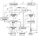
図1に、本発明を適用した超音波診断装置の一実施形態のブロック構成図を示す。同図において、探触子1は複数の超音波振動子が内蔵されて形成されている。この探触子1は、超音波送受信部2から出力される超音波信号を超音波に変換して被検体100の診断部位に送信するとともに、被検体100の診断部位から発生する超音波を反射エコー信号に変換して超音波送受信部2に出力するようになっている。超音波送受信部2は、探触子1から出力される反射エコー信号を増幅、検波、整相加算等の受信処理して、超音波画像構成部3に出力するようになっている。超音波画像構成部3は、入力される反射エコー信号に基づいて診断部位の超音波画像(Bモード像)を再構成して、シネメモリ部4のメモリに格納する。シネメモリ部4は、超音波画像を2次元画像データのフレーム単位でフレームNo.を付して記録するようになっている。
FIG. 1 shows a block diagram of an embodiment of an ultrasonic diagnostic apparatus to which the present invention is applied. In the figure, the
また、磁気位置センサ5は、被検体100の3次元座標系を基準に、探触子1の位置および傾き角度(姿勢)を検出し、その検出情報6を画像位置演算部7に出力するようになっている。画像位置演算部7は、探触子1の位置および姿勢に基づいて撮像された超音波画像の断面位置を演算により求め、シネメモリ部4からフレームNo.通知14によって入力される超音波画像のフレームNo.に対応付けて保存するようになっている。
The
一方、シネメモリ部4に一旦格納された超音波画像は、表示画像制御部8を介して画像表示部9に転送され、リアルタイムで画面に表示されるようになっている。操作パネル10は、キーボードやトラックボール等を有して構成されている。操作パネル10からは、超音波画像の表示条件の指定、リファレンス画像を表示させる指令、画像表示部9の画面上に表示する超音波画像及びリファレンス画像の表示方法などの表示モードの指令などを入力するようになっている。
On the other hand, the ultrasonic image once stored in the
例えば、超音波画像の表示倍率などの表示条件が指定されると、操作パネル10から表示条件指示11が画像表示条件管理部12に入力される。ここで、表示条件としては、表示倍率の他、例えば、探触子1によりリアルタイムで撮像される超音波画像の視野の上下移動及びズームなどを指定できるようになっている。また、探触子1の種類によって画像形状が扇形又は扇形の要部を切除した形状になることから、探触子1の種類を画像形状の情報として入力するようになっている。
For example, when a display condition such as a display magnification of the ultrasonic image is designated, a
画像表示条件管理部12は、操作パネル10から入力される表示条件指示11を記憶するとともに、表示条件指示11を超音波画像構成部3及び必要に応じてシネメモリ部4に出力するようになっている。これにより、超音波画像構成部3は、表示条件指示11に適合した表示条件の超音波画像を再構成させるようになっている。つまり、超音波送受信部2から入力される反射エコー信号に基づいて、超音波画像の表示倍率、上下移動及びズーム処理を行った超音波画像を再構成して、シネメモリ部4に格納するようになっている。シネメモリ部4に格納された超音波画像は表示画像制御部8を介して画像表示部9に表示されるようになっている。また、後述するように、画像表示条件管理部12は、リファレンス画像構成部16に表示条件指示11を出力して、指示に適合したリファレンス画像を読み出させるようにしている。
The image display
また、操作パネル10から入力される超音波画像及びリファレンス画像の表示モード指示13は、表示画像制御部8に入力されるようになっている。ここで、画像の表示モードには、リファレンス画像と超音波画像について、いずれか一方を切り替えて表示する態様、並べて表示する態様、その他メニュー画面等に表示される表示モードを選択して指定することができるようになっている。表示画像制御部8は、リファレンス画像と超音波画像を指定された表示モードによって画像表示部9に表示させるようになっている。
The
次に、本実施形態の特徴部に係るリファレンス画像の生成に係る部分について説明する。ボリュームデータ取得処理部15に、本実施形態の超音波診断装置、あるいは他の超音波診断装置、X線CT装置、MRI装置などの画像診断装置によって撮像された同一の被検体100についてのボリュームデータが格納されるようになっている。このボリュームデータには、撮像した画像診断装置の空間座標系に基づいた座標情報が付与されている。なお、図1中に破線21、22、23を用いて表したラインは、本実施形態の超音波診断装置によりボリュームデータを取得する場合に用いるラインであり、詳細な手順については後述する。また、ボリュームデータ取得処理部15は、本実施形態に示すように、超音波診断装置の内部に設けてもよいが、CD等の記録媒体やネットワーク上のサーバに設けたり、あるいはネットワークで接続されたX線CT装置又はMRI装置から直接取得するようにしてもよい。
Next, a part related to generation of a reference image according to the characteristic part of the present embodiment will be described. Volume data for the
リファレンス画像構成部16は、画像位置情報取得部17を介して画像位置演算部7からリアルタイム超音波画像の断面位置情報18を取り込んで、ボリュームデータ取得処理部15のボリュームデータから断面位置情報18に対応する断面位置のリファレンス画像を切り出して、再構成するようになっている。なお、画像位置情報取得部17は、シネメモリ部4から通知されるリアルタイム超音波画像のフレームNo.に対応するリアルタイム超音波画像の断面位置情報18を画像位置演算部7から取得する。リファレンス画像構成部16により再構成されたリファレンス画像は、表示画像制御部8を介して画像表示部9に表示可能になっている。
The reference
特に、リファレンス画像構成部16は、画像表示条件管理部12から入力される表示条件指示11に従い、リアルタイム超音波画像の表示倍率に一致させてリファレンス画像を切り出すようになっている。例えば、リファレンス画像の画素間寸法とリアルタイム超音波画像の画素間寸法の比を予め設定しておき、その比と画像表示条件管理部12から指示された表示倍率に基づいてリファレンス画像の表示倍率を求めて切り出すようにする。また、探触子1の種類の情報に基づいてリアルタイム超音波画像の形状を判断し、これに基づいてリファレンス画像の形状を扇形又は扇形の要部を切除した形状に切り出すようになっている。さらに、上下移動及びズームの場合は、リアルタイム画像の表示倍率や形状と共に表示開始深度や表示位置を判断し、リファレンス画像の表示位置、表示倍率及び形状を一致させて切り出すようになっている。
In particular, the reference
次に、本実施形態を用いて、リアルタイム超音波画像を撮像しながら同一部位のリファレンス画像を画像表示部9に表示して対比観察する場合の手順について説明する。
Next, a procedure in the case of performing a comparative observation by displaying a reference image of the same part on the
(観察前処理)
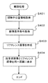
まず、実際の対比観察をする前に、予め取得しなければならないボリュームデータの取得処理手順を図2に示す。同図に示すように、ボリュームデータ取得処理部15に格納されているボリュームデータのうち、参照したいボリュームデータを指定する(S201)。指定の方法は、画像表示部9に表示されたメニュー等により、格納先アドレスや名称を指示することにより行なう。
(Pre-observation processing)
First, FIG. 2 shows a volume data acquisition processing procedure that must be acquired in advance before actual contrast observation. As shown in the figure, among the volume data stored in the volume data
次に、指定したボリュームデータ上で、探触子1の基準点位置と一致する位置を直交座標のX,Y,Z座標で指定する(S202)。この際、使用する探触子1に関する情報も与え、探触子1の形状により異なる最大表示幅等についても考慮して、基準点位置の設定が行なえるようにしてもよい。
Next, on the designated volume data, a position that coincides with the reference point position of the
次に、指定した基準点位置の設定を超音波診断装置側で行なう。つまり、探触子1を被検体100上の指定した基準点と同様の部位に当て、操作パネル10等により、設定実行を入力する(S203)。これにより、超音波画像とリファレンス画像との位置関係を対応付けることができる。ここまでが、実際の対比観察を行なうまでの準備処理となる。
Next, the designated reference point position is set on the ultrasonic diagnostic apparatus side. That is, the
(画像位置情報の取得処理)
ここで、図3を参照して、画像位置演算部7における断面位置情報18を演算する処理、及び画像位置情報取得部17における断面位置情報18の取得処理について説明する。なお、画像位置演算部7は、リアルタイム時に、リアルタイム超音波画像の断面位置情報18を演算する。また、画像位置情報取得部17は、リアルタイム時におけるリファレンス画像用の断面位置情報18の取得処理と、フリーズ時におけるリファレンス画像用の断面位置情報18の取得処理を行なうようになっている。
(Image position information acquisition process)
Here, with reference to FIG. 3, processing for calculating the
まず、画像位置演算部7は、フリーズか否かを判定する(S301)。この判定は、シネメモリ部4から通知されるフレームNo.が変化するときはリアルタイムとし、フレームNo.が変化しないときはフリーズと判定することができる。但し、フリーズの判定は、この方法に限られるものではなく、図示していないが、操作パネル10に入力されるフリーズ指令を画像位置演算部7に出力し、これに基づいて判定するようにすることができる。
First, the image
リアルタイムと判定された場合は、磁気位置センサ5から探触子1の位置及び姿勢の検出情報6を取り込んで、リアルタイム超音波画像の断面位置の座標情報を演算により求め、断面位置情報18として保存する(S302)。次に、シネメモリ部4から通知されるリアルタイム超音波画像のフレームNo.を取得する(S303)。そして、断面位置情報18とフレームNo.を対応付けてメモリに格納する(S304)。
If it is determined as real time, the
画像位置情報取得部17は、リアルタイム/フリーズの双方に共通の処理として、リファレンス画像を切り出すために、シネメモリ部4から通知される現在表示されている超音波画像のフレームNo.を取得し(S305)、次いで、そのフレームNo.に対応する断面位置情報18を画像位置演算部7から取得する(S306)。
As a process common to both real time and freeze, the image position
このようにして、リアルタイム又はフリーズ時に画像表示部9に表示される超音波画像に対応する断面位置情報18が取得され、これに基づいてリファレンス画像構成部16は、リファレンス画像をボリュームデータから切り出して、表示画像制御部8を介して画像表示部9に表示させる。
Thus, the
(対比観察)
図4を参照して、実際に対比観察を行なう際の処理手順を説明する。画像表示部9の画像を見ながら、探触子1を観察したい関心領域に移動する。探触子1を移動すると、磁気位置サンサ5から探触子1の位置と姿勢が逐一取得され、取得された検出情報6に基づいて画像位置演算部7において、リアルタイム超音波画像の断面位置の座標が演算される。演算された断面位置の座標は、シネメモリ部4から通知されるフレームNo.に対応付けて記録される(S401)。
(Contrast observation)
With reference to FIG. 4, the processing procedure when actually performing the contrast observation will be described. While looking at the image on the
次に、リファレンス画像構成部16は、画像表示条件管理部12からリファレンス画像表示の起動指令が出力されている場合、表示倍率、上下移動量、ズーム情報等の超音波画像の表示条件を取得する(S402)。また、画像位置情報取得部17からリアルタイム超音波画像の断面位置情報18を取得し、その断面位置に対応するボリュームデータ上の断面位置の画像を抽出する。さらに、超音波画像の表示条件に応じて抽出したリファレンス画像を再構成する(S403)。つまり、画像表示条件管理部12から指示される表示条件に基づいて、抽出したリファレンス画像を拡大又は縮小したり、画像の上下移動やズーム機能に基づいて、表示位置を限定する。さらに、探触子1の形状に応じてセクタ画像の場合は、扇形に画像を切り抜いたり、コンベックス画像の場合は、扇形の上側を超音波画像の表示に合わせ弧状等に切り抜いたりする。これにより、リアルタイム超音波画像と同一部位、同一断面のリファレンス画像を、同一表示条件によって画像表示部9に描画させることができる。
Next, when a reference image display activation command is output from the image display
また、このようにして作成されたリファレンス画像を、表示画像制御部8に入力されている表示モード指示13に従って、リアルタイム超音波画像とともに、あるいは単独で画像表示部9に描画させる(S404)。この表示形態は、前述したように、リファレンス画像と超音波画像について、いずれか一方を切り替えて表示する態様、並べて表示する態様、その他メニュー画面等によって選択された表示モードにより表示される。例えば、リファレンス画像を表示する際に、同一画面上にボリュームデータの3次元画像を表示してもよい。また、リファレンス画像は、超音波画像の動きに合わせて、動画像表示するようにできることは言うまでもない。
Further, the reference image created in this way is drawn on the
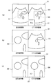
このようにして、図5に示すように、画像表示部9に表示される超音波画像とリファレンス画像の表示条件が合わせて表示される。つまり、図5に示した表示画像の一例は、リファレンス画像としてX線CT画像又はMR画像を用いた例である。同図(a)に示すように、表示画面31の左半分にリアルタイム又はフリーズ時の超音波画像32が表示され、右半分にリファレンス画像33が表示される。図示のように、リファレンス画像33は、超音波画像32と同じ表示倍率で、かつ同じ画像形状により表示される。したがって、両画像の対比観察を容易に行うことができる。
In this way, as shown in FIG. 5, the display conditions of the ultrasonic image and the reference image displayed on the
一方、操作パネル10から超音波画像32に関心領域34を設定し、この領域についてズームアップ指令を入力すると、同図(b)に示すように、関心領域34の部分を拡大した超音波画像35が表示される。これに対し、リファレンス画像33を同図(a)の表示倍率のまま表示すると、同図(b)を対比して明らかなように、違和感があり、対比観察しにくい。この点、本実施形態によれば、同図(c)に示すように、ズームアップ表示された超音波画像35に合わせて、リファレンス画像36が拡大表示される。
On the other hand, when a region of
また、図5(a)又は図5(c)に示したように、表示画面31の一部領域に、関心領域34の部位の3次元画像37を表示することもできる。さらに、図5(a)に示すように、リファレンス画像33の解像度がよい場合は、リファレンス画像33に関心領域38を設定し、この関心領域38に基づいて、超音波画像35を拡大表示するようにしてもよい。関心領域34,38は、操作パネル10からに入力によって、拡大、縮小、上下左右の移動を操作することができる。また、図5(c)の表示状態において、操作パネル10を操作して関心領域を拡大、縮小、上下左右に移動できる。
5A or 5C, a three-
上述したように、本実施形態によれば、観察者は、リアルタイム表示される超音波画像又はフリーズ表示される超音波画像に対応した同一描出位置、同一画像表示条件のリファレンス画像が画面に表示されるから、両画像の対比観察を容易に行うことができる。その結果、両者の画像を違和感なく対比観察できるから、治療時のガイドラインとしての利用や、患者の治療効果判断に利用する際の使い勝手が向上し、診断効果を向上させることができる。また、超音波画像による診断の教育に役立たせることができる。 As described above, according to the present embodiment, the observer displays the reference image of the same rendering position and the same image display condition corresponding to the ultrasonic image displayed in real time or the ultrasonic image displayed as freeze display on the screen. Therefore, the contrast observation of both images can be easily performed. As a result, since both images can be compared and observed without a sense of incongruity, the use as a guideline at the time of treatment and the usability when used for determining the treatment effect of a patient are improved, and the diagnosis effect can be improved. In addition, it can be used for education of diagnosis using ultrasonic images.
(リファレンス画像の生成タイミング)
上記実施形態では、超音波画像とリファレンス画像の生成時間に相違がある場合の処理について説明しなかった。ところが、一般に、超音波画像に対応するリファレンス画像をボリュームデータから切り出して再構成する処理は、リアルタイム超音波画像を再構成する処理よりも時間がかかる。
(Reference image generation timing)
In the above embodiment, the processing when there is a difference between the generation times of the ultrasonic image and the reference image has not been described. However, in general, the process of extracting and reconstructing a reference image corresponding to an ultrasound image from volume data takes more time than the process of reconstructing a real-time ultrasound image.
そこで、図6を用いて、ボリュームデータからリファレンス画像を切り出して再構成する処理と、リアルタイム超音波画像を再構成する処理のタイミングの一例を説明する。図6において、リアルタイム超音波画像41は周期的に撮像され、フレームNo.1、2、・・・が付されて、シネメモリ部4に順次格納される。また、画像位置演算部7は、フレームNo.の更新タイミング42ごとに、磁気位置センサ5から探触子1の位置と姿勢の検出情報6を取り込み、リアルタイム超音波画像の断面位置情報18を演算し、フレームNo.に対応付けて記録する。
An example of the timing of processing for cutting out and reconstructing a reference image from volume data and processing for reconstructing a real-time ultrasound image will be described with reference to FIG. In FIG. 6, real-time
一方、リファレンス画像構成部16は、超音波画像の数フレームにつき、リファレンス画像を1フレーム生成する。例えば、フレームNo.1の更新タイミングに処理を開始し、フレームNo.3の更新タイミング時にフレームNo.1の超音波画像に対応するリファレンス画像43を表示する。また、フレームNo.3の更新タイミングに処理を開始し、フレームNo.6の更新タイミング時にフレームNo.3の超音波画像に対応するリファレンス画像44を表示する。
On the other hand, the reference
また、フレームNo.6の超音波画像が表示されているタイミングに、操作パネル10からフリーズオンの指令45が入力されると、フリーズオン時のフレームNo.を取り込み、そのフレームNo.に対応する断面位置情報18を画像位置演算部7から取得する。そして、フリーズオン時の超音波画像に対応するリファレンス画像46を生成して表示する。また、シネメモリ部4に格納されている超音波画像をシネ再生する場合は、フリーズ時と同様に、シネメモリ部4から通知されるフレームNo.に対応する断面位置情報18を取得して、リファレンス画像を生成して表示する。また、シネ再生時の表示条件は、シネメモリ画像の表示条件であるフリーズ直前の表示条件を超音波画像構成部3から取得して、リファレンス画像を生成する。
Also, frame No. When the freeze-on
さらに、超音波画像のフレームレートと、リファレンス画像の生成時間を考慮して、超音波画像の画面表示を若干遅らせることも可能である。この遅れ時間によって、断面位置情報18を取得する処理、及び画像の表示条件を合わせるための処理を加えてもよい。また、2つの画像の位置や時間のずれを画面上に、図や文字等で表示したりしてしらせてもよい。
Furthermore, it is possible to slightly delay the screen display of the ultrasonic image in consideration of the frame rate of the ultrasonic image and the generation time of the reference image. Depending on the delay time, processing for obtaining the
また、リアルタイム時において、探触子1の動きの大小を監視し、探触子1の動きの大きい場合は、リファレンス画像の生成を中断し、動きが小さいか、あるいは止まった場合にリファレンス画像の生成を再開させるようにすることができる。これによれば、単に関心部位を探索するために探触子1を移動させている操作の場合には、リファレンス画像の描出は不要であるから、不要な処理を排除することができる。
Also, in real time, the magnitude of the movement of the
(超音波画像のボリュームデータ収集)
上記の説明では、リファレンス画像用のボリュームデータとしてX線CT画像又はMR像を例に説明したが、前述したように、図1の実施形態の超音波診断装置によりリファレンス画像用のボリュームデータを収集することができる。この場合、被検体100の診断部位の体表面に探触子1を当てて一方向に移動操作し、診断部位を含む周辺領域の超音波画像を獲得する。そして、ボリュームデータ取得処理部15は、シネメモリ部4からリアルタイム超音波画像をフレームNo.と共に取り込み、画像位置演算部7からそのフレームNo.に対応する断面位置情報18を取り込んで、超音波画像の3次元ボリュームデータを収集する。
(Volume data collection of ultrasound images)
In the above description, the X-ray CT image or the MR image has been described as an example of the reference image volume data. However, as described above, the reference image volume data is collected by the ultrasonic diagnostic apparatus of the embodiment of FIG. can do. In this case, the
(表示モード例)
次に、表示画像制御部8の切換えによる画像表示部9の表示画面における表示モードについて、図7を参照して説明する。操作パネル10の各々のキーに割り当てられた機能により、あるいは図7に示したアイコン51等の機能により、例えば、図7の(a)〜(e)に示すように表示モードを任意に選択して切り替えるようにすることができる。同図(a)は、超音波画像52とリファレンス画像53との2画面表示する典型的な対比表示例である。同図(b)は、超音波画像52と同一表示条件によるリファレンス画像54の2画面表示例である。同図(c)、(d)は、それぞれ、超音波画像52とリファレンス画像53の1画面表示例である。同図(e)は、超音波画像52、リファレンス画像53及リファレンス画像に係る3D画像55の表示画面の表示例である。ここで、同図(e)の3D画像には、リファレンス画像53の断面位置を示すカットプレート56を表示することもできる。
(Display mode example)
Next, a display mode on the display screen of the
図8に、画像表示部9の表示画面に表示される実際の表示モードの一例を示す。同図(a)は、X線CT画像のボリュームデータを用いて、本実施形態のリファレンス画像を生成表示させる際のセットアップ時の表示画面である。同図に基づいて、探触子1の基準点を設定し、その位置に探触子1を当ててボリュームデータの座標系と超音波診断装置の座標系の対応付けを設定する。同図(b)は、図7(b)に対応する表示モードであり、左側の超音波画像と、右側のリファレンス画像とが同一表示条件によって表示されている。
FIG. 8 shows an example of an actual display mode displayed on the display screen of the
また、図7、図8により説明した表示モードは、リアルタイム超音波画像の表示に限られるものではなく、フリーズ時あるいはシネ再生時にも適用することができる。 Further, the display mode described with reference to FIGS. 7 and 8 is not limited to the display of the real-time ultrasonic image, and can be applied at the time of freezing or cine reproduction.
また、ボリュームデータ取得処理部15に格納されている超音波画像の3次元ボリュームデータとX線CT画像などの3次元ボリュームデータに基づいて、超音波画像とリファレンス画像の2つの画像をそれぞれ3次元表示することも可能である。この3次元表示においても、2つの画像の3D構成位置や、3D表示方向、及び表示条件は一致させることができる。
Further, based on the three-dimensional volume data of the ultrasonic image and the three-dimensional volume data such as the X-ray CT image stored in the volume data
1 探触子
2 超音波送受信部
3 超音波画像構成部
4 シネメモリ部
5 磁気位置センサ
7 画像位置演算部
8 表示画像制御部
9 画像表示部
10 操作パネル
12 画像表示条件管理部
15 ボリュームデータ取得処理部
16 リファレンス画像構成部
17 画像位置情報取得部
DESCRIPTION OF
Claims (7)
前記リファレンス画像は、前記超音波画像の表示条件に合わせて描画されることを特徴とする超音波診断装置。 From the ultrasound image reconstructed based on the reflected echo signal received by the ultrasound probe that transmits and receives ultrasound to and from the subject, and the three-dimensional image data of the subject imaged in advance, the ultrasound In an ultrasonic diagnostic apparatus that displays a reference image obtained by cutting out an image of a cross-sectional position corresponding to an image on a display screen in a comparable manner,
The ultrasonic diagnostic apparatus, wherein the reference image is drawn according to display conditions of the ultrasonic image.
前記入力手段から入力される指示に従って前記画像表示手段の画面に表示させる画像の表示条件を管理するとともに、前記超音波画像構成手段と前記リファレンス画像構成手段とに表示条件を出力する画像表示条件管理手段を設けてなることを特徴とする超音波診断装置。 Ultrasound image constructing means for reconstructing an ultrasound image based on a reflected echo signal measured by an ultrasound probe that transmits and receives ultrasound to and from the subject, and the position and orientation of the ultrasound probe Calculated by the image position calculating means for calculating the cross-sectional position of the ultrasonic image based on the detected information, the recording medium on which the three-dimensional image data of the subject imaged in advance is recorded, and the image position calculating means A reference image constituting unit that cuts out a reference image corresponding to a cross-sectional position of the ultrasonic image from the three-dimensional image data, an image display unit, and an input unit;
Image display condition management for managing display conditions of images to be displayed on the screen of the image display means in accordance with instructions input from the input means and outputting display conditions to the ultrasonic image construction means and the reference image construction means An ultrasonic diagnostic apparatus characterized by comprising means.
Priority Applications (1)
| Application Number | Priority Date | Filing Date | Title |
|---|---|---|---|
| JP2004365811A JP2006167267A (en) | 2004-12-17 | 2004-12-17 | Ultrasonograph |
Applications Claiming Priority (1)
| Application Number | Priority Date | Filing Date | Title |
|---|---|---|---|
| JP2004365811A JP2006167267A (en) | 2004-12-17 | 2004-12-17 | Ultrasonograph |
Related Child Applications (1)
| Application Number | Title | Priority Date | Filing Date |
|---|---|---|---|
| JP2010256778A Division JP4690503B2 (en) | 2010-11-17 | 2010-11-17 | Ultrasonic diagnostic equipment |
Publications (2)
| Publication Number | Publication Date |
|---|---|
| JP2006167267A true JP2006167267A (en) | 2006-06-29 |
| JP2006167267A5 JP2006167267A5 (en) | 2008-01-31 |
Family
ID=36668603
Family Applications (1)
| Application Number | Title | Priority Date | Filing Date |
|---|---|---|---|
| JP2004365811A Pending JP2006167267A (en) | 2004-12-17 | 2004-12-17 | Ultrasonograph |
Country Status (1)
| Country | Link |
|---|---|
| JP (1) | JP2006167267A (en) |
Cited By (30)
| Publication number | Priority date | Publication date | Assignee | Title |
|---|---|---|---|---|
| JP2008136867A (en) * | 2006-11-30 | 2008-06-19 | General Electric Co <Ge> | Imaging parameter storage method |
| JP2008142151A (en) * | 2006-12-07 | 2008-06-26 | Matsushita Electric Ind Co Ltd | Ultrasonic diagnostic apparatus and ultrasonic diagnostic system |
| JP2008173255A (en) * | 2007-01-18 | 2008-07-31 | Toshiba Corp | Ultrasonic image diagnostic apparatus and ultrasonic image diagnostic program |
| JP2008188417A (en) * | 2007-01-11 | 2008-08-21 | Toshiba Corp | Three-dimensional image diagnosis system |
| JP2008188288A (en) * | 2007-02-06 | 2008-08-21 | Toshiba Corp | Ultrasonic diagnostic equipment and ultrasonic image display device |
| JP2008188193A (en) * | 2007-02-05 | 2008-08-21 | Hitachi Medical Corp | Medical image diagnostic apparatus |
| JP2008237883A (en) * | 2007-03-01 | 2008-10-09 | Toshiba Corp | Magnetic resonance imaging apparatus and magnetic resonance imaging method |
| WO2010007860A1 (en) * | 2008-07-15 | 2010-01-21 | 株式会社 日立メディコ | Ultrasound diagnostic device and method for displaying probe operation guide of the same |
| JP2010017537A (en) * | 2008-06-10 | 2010-01-28 | Toshiba Corp | Ultrasonic diagnostic apparatus |
| JP2010246630A (en) * | 2009-04-13 | 2010-11-04 | Aloka Co Ltd | Ultrasound diagnostic apparatus |
| JP2010279425A (en) * | 2009-06-02 | 2010-12-16 | Toshiba Corp | Ultrasonic diagnostic apparatus |
| JP2011500250A (en) * | 2007-10-26 | 2011-01-06 | コーニンクレッカ フィリップス エレクトロニクス エヌ ヴィ | Closed-loop registration control for multi-modality soft tissue imaging |
| JP2011011001A (en) * | 2009-07-06 | 2011-01-20 | Toshiba Corp | Ultrasonic diagnostic apparatus and processing program therefor |
| JP2011024827A (en) * | 2009-07-27 | 2011-02-10 | Toshiba Corp | Ultrasonograph |
| JP2011078440A (en) * | 2009-10-02 | 2011-04-21 | Ge Medical Systems Global Technology Co Llc | Medical image diagnostic apparatus |
| JP2011115324A (en) * | 2009-12-02 | 2011-06-16 | Hitachi Medical Corp | Ultrasonograph and ultrasonic image display method |
| JP2011115456A (en) * | 2009-12-04 | 2011-06-16 | Toshiba Corp | Ultrasonic diagnostic apparatus and control program for image data display |
| JP2011125567A (en) * | 2009-12-18 | 2011-06-30 | Canon Inc | Information processor, information processing method, information processing system and program |
| JP2012061261A (en) * | 2010-09-17 | 2012-03-29 | Toshiba Corp | Ultrasonic diagnostic apparatus, medical image processor, and medical image processing program |
| JP2012223416A (en) * | 2011-04-21 | 2012-11-15 | Ge Medical Systems Global Technology Co Llc | Ultrasonic diagnosis apparatus and program for controlling the same |
| WO2013035393A1 (en) * | 2011-09-08 | 2013-03-14 | 株式会社 日立メディコ | Ultrasound diagnostic device and ultrasound image display method |
| JP2013123582A (en) * | 2011-12-15 | 2013-06-24 | Hitachi Aloka Medical Ltd | Ultrasonic diagnostic apparatus and image display method |
| JP2014097162A (en) * | 2012-11-14 | 2014-05-29 | Toshiba Corp | Ultrasonic image diagnostic apparatus |
| WO2014115751A1 (en) * | 2013-01-23 | 2014-07-31 | 株式会社 東芝 | Ultrasonic diagnosis device |
| JP2014184341A (en) * | 2014-07-08 | 2014-10-02 | Toshiba Corp | Ultrasonic diagnostic apparatus |
| US8852106B2 (en) | 2009-04-13 | 2014-10-07 | Hitachi Aloka Medical, Ltd. | Ultrasound diagnostic apparatus |
| WO2014199631A1 (en) * | 2013-06-11 | 2014-12-18 | 株式会社 東芝 | Ultrasonic diagnostic device |
| JP2015136445A (en) * | 2014-01-21 | 2015-07-30 | 株式会社東芝 | Ultrasonic diagnostic apparatus, image processing apparatus, and program |
| WO2017038300A1 (en) * | 2015-09-02 | 2017-03-09 | 株式会社日立製作所 | Ultrasonic imaging device, and image processing device and method |
| CN107072633A (en) * | 2014-10-24 | 2017-08-18 | 通用电气公司 | A kind of method and device that area-of-interest is shown on current ultrasonic image |
Citations (8)
| Publication number | Priority date | Publication date | Assignee | Title |
|---|---|---|---|---|
| JPH02193655A (en) * | 1989-01-24 | 1990-07-31 | Fujitsu Ltd | Ultrasonic diagnostic device |
| JPH02203845A (en) * | 1989-02-01 | 1990-08-13 | Fujitsu Ltd | Ultrasonic wave diagnostic device |
| JPH09322894A (en) * | 1996-06-07 | 1997-12-16 | Matsushita Electric Ind Co Ltd | Ultrasonograph |
| JPH10151131A (en) * | 1996-11-25 | 1998-06-09 | Hitachi Medical Corp | Ultrasonograph |
| JPH10305031A (en) * | 1997-05-08 | 1998-11-17 | Aloka Co Ltd | Ultrasonic diagnostic system |
| JP2002263101A (en) * | 2001-03-06 | 2002-09-17 | Aloka Co Ltd | Ultrasonic diagnostic device |
| JP2003180697A (en) * | 2001-12-18 | 2003-07-02 | Olympus Optical Co Ltd | Ultrasonic diagnostic equipment |
| WO2004098414A1 (en) * | 2003-05-08 | 2004-11-18 | Hitachi Medical Corporation | Reference image display method for ultrasonography and ultrasonograph |
-
2004
- 2004-12-17 JP JP2004365811A patent/JP2006167267A/en active Pending
Patent Citations (8)
| Publication number | Priority date | Publication date | Assignee | Title |
|---|---|---|---|---|
| JPH02193655A (en) * | 1989-01-24 | 1990-07-31 | Fujitsu Ltd | Ultrasonic diagnostic device |
| JPH02203845A (en) * | 1989-02-01 | 1990-08-13 | Fujitsu Ltd | Ultrasonic wave diagnostic device |
| JPH09322894A (en) * | 1996-06-07 | 1997-12-16 | Matsushita Electric Ind Co Ltd | Ultrasonograph |
| JPH10151131A (en) * | 1996-11-25 | 1998-06-09 | Hitachi Medical Corp | Ultrasonograph |
| JPH10305031A (en) * | 1997-05-08 | 1998-11-17 | Aloka Co Ltd | Ultrasonic diagnostic system |
| JP2002263101A (en) * | 2001-03-06 | 2002-09-17 | Aloka Co Ltd | Ultrasonic diagnostic device |
| JP2003180697A (en) * | 2001-12-18 | 2003-07-02 | Olympus Optical Co Ltd | Ultrasonic diagnostic equipment |
| WO2004098414A1 (en) * | 2003-05-08 | 2004-11-18 | Hitachi Medical Corporation | Reference image display method for ultrasonography and ultrasonograph |
Cited By (42)
| Publication number | Priority date | Publication date | Assignee | Title |
|---|---|---|---|---|
| JP2008136867A (en) * | 2006-11-30 | 2008-06-19 | General Electric Co <Ge> | Imaging parameter storage method |
| JP2008142151A (en) * | 2006-12-07 | 2008-06-26 | Matsushita Electric Ind Co Ltd | Ultrasonic diagnostic apparatus and ultrasonic diagnostic system |
| JP2008188417A (en) * | 2007-01-11 | 2008-08-21 | Toshiba Corp | Three-dimensional image diagnosis system |
| JP2013063342A (en) * | 2007-01-11 | 2013-04-11 | Toshiba Corp | Three-dimensional diagnostic imaging system |
| JP2008173255A (en) * | 2007-01-18 | 2008-07-31 | Toshiba Corp | Ultrasonic image diagnostic apparatus and ultrasonic image diagnostic program |
| JP2008188193A (en) * | 2007-02-05 | 2008-08-21 | Hitachi Medical Corp | Medical image diagnostic apparatus |
| JP2008188288A (en) * | 2007-02-06 | 2008-08-21 | Toshiba Corp | Ultrasonic diagnostic equipment and ultrasonic image display device |
| JP2008237883A (en) * | 2007-03-01 | 2008-10-09 | Toshiba Corp | Magnetic resonance imaging apparatus and magnetic resonance imaging method |
| US8885897B2 (en) | 2007-10-26 | 2014-11-11 | Koninklijke Philips N.V. | Closed loop registration control for multi-modality soft tissue imaging |
| JP2011500250A (en) * | 2007-10-26 | 2011-01-06 | コーニンクレッカ フィリップス エレクトロニクス エヌ ヴィ | Closed-loop registration control for multi-modality soft tissue imaging |
| JP2010017537A (en) * | 2008-06-10 | 2010-01-28 | Toshiba Corp | Ultrasonic diagnostic apparatus |
| US9592028B2 (en) | 2008-06-10 | 2017-03-14 | Toshiba Medical Systems Corporation | Ultrasonic diagnostic apparatus |
| WO2010007860A1 (en) * | 2008-07-15 | 2010-01-21 | 株式会社 日立メディコ | Ultrasound diagnostic device and method for displaying probe operation guide of the same |
| JP5586465B2 (en) * | 2008-07-15 | 2014-09-10 | 株式会社日立メディコ | Ultrasonic diagnostic equipment |
| US8376951B2 (en) | 2008-07-15 | 2013-02-19 | Hitachi Medical Corporation | Ultrasonic diagnostic apparatus and method for displaying probe operation guide |
| US8852106B2 (en) | 2009-04-13 | 2014-10-07 | Hitachi Aloka Medical, Ltd. | Ultrasound diagnostic apparatus |
| JP2010246630A (en) * | 2009-04-13 | 2010-11-04 | Aloka Co Ltd | Ultrasound diagnostic apparatus |
| JP2010279425A (en) * | 2009-06-02 | 2010-12-16 | Toshiba Corp | Ultrasonic diagnostic apparatus |
| JP2011011001A (en) * | 2009-07-06 | 2011-01-20 | Toshiba Corp | Ultrasonic diagnostic apparatus and processing program therefor |
| JP2011024827A (en) * | 2009-07-27 | 2011-02-10 | Toshiba Corp | Ultrasonograph |
| JP2011078440A (en) * | 2009-10-02 | 2011-04-21 | Ge Medical Systems Global Technology Co Llc | Medical image diagnostic apparatus |
| JP2011115324A (en) * | 2009-12-02 | 2011-06-16 | Hitachi Medical Corp | Ultrasonograph and ultrasonic image display method |
| JP2011115456A (en) * | 2009-12-04 | 2011-06-16 | Toshiba Corp | Ultrasonic diagnostic apparatus and control program for image data display |
| JP2011125567A (en) * | 2009-12-18 | 2011-06-30 | Canon Inc | Information processor, information processing method, information processing system and program |
| JP2012061261A (en) * | 2010-09-17 | 2012-03-29 | Toshiba Corp | Ultrasonic diagnostic apparatus, medical image processor, and medical image processing program |
| JP2012223416A (en) * | 2011-04-21 | 2012-11-15 | Ge Medical Systems Global Technology Co Llc | Ultrasonic diagnosis apparatus and program for controlling the same |
| US9480457B2 (en) | 2011-09-08 | 2016-11-01 | Hitachi Medical Corporation | Ultrasound diagnostic device and ultrasound image display method |
| CN103781426A (en) * | 2011-09-08 | 2014-05-07 | 株式会社日立医疗器械 | Ultrasound diagnostic device and ultrasound image display method |
| WO2013035393A1 (en) * | 2011-09-08 | 2013-03-14 | 株式会社 日立メディコ | Ultrasound diagnostic device and ultrasound image display method |
| JPWO2013035393A1 (en) * | 2011-09-08 | 2015-03-23 | 株式会社日立メディコ | Ultrasonic diagnostic apparatus and ultrasonic image display method |
| JP2013123582A (en) * | 2011-12-15 | 2013-06-24 | Hitachi Aloka Medical Ltd | Ultrasonic diagnostic apparatus and image display method |
| JP2014097162A (en) * | 2012-11-14 | 2014-05-29 | Toshiba Corp | Ultrasonic image diagnostic apparatus |
| JP2014158693A (en) * | 2013-01-23 | 2014-09-04 | Toshiba Corp | Ultrasound diagnostic device |
| WO2014115751A1 (en) * | 2013-01-23 | 2014-07-31 | 株式会社 東芝 | Ultrasonic diagnosis device |
| US10966687B2 (en) | 2013-01-23 | 2021-04-06 | Canon Medical Systems Corporation | Ultrasonic diagnostic apparatus |
| WO2014199631A1 (en) * | 2013-06-11 | 2014-12-18 | 株式会社 東芝 | Ultrasonic diagnostic device |
| JP2014239731A (en) * | 2013-06-11 | 2014-12-25 | 株式会社東芝 | Ultrasound diagnostic device |
| JP2015136445A (en) * | 2014-01-21 | 2015-07-30 | 株式会社東芝 | Ultrasonic diagnostic apparatus, image processing apparatus, and program |
| JP2014184341A (en) * | 2014-07-08 | 2014-10-02 | Toshiba Corp | Ultrasonic diagnostic apparatus |
| CN107072633A (en) * | 2014-10-24 | 2017-08-18 | 通用电气公司 | A kind of method and device that area-of-interest is shown on current ultrasonic image |
| WO2017038300A1 (en) * | 2015-09-02 | 2017-03-09 | 株式会社日立製作所 | Ultrasonic imaging device, and image processing device and method |
| JPWO2017038300A1 (en) * | 2015-09-02 | 2018-04-26 | 株式会社日立製作所 | Ultrasonic imaging apparatus, image processing apparatus, and method |
Similar Documents
| Publication | Publication Date | Title |
|---|---|---|
| JP2006167267A (en) | Ultrasonograph | |
| KR101140525B1 (en) | Method and apparatus for extending an ultrasound image field of view | |
| KR100718411B1 (en) | Three-dimensional ultrasound data display using multiple cut planes | |
| EP1623674B1 (en) | Reference image display method for ultrasonography and ultrasonograph | |
| JP4693465B2 (en) | Three-dimensional ultrasonic diagnostic apparatus and volume data display area setting method | |
| JP5400466B2 (en) | Diagnostic imaging apparatus and diagnostic imaging method | |
| JP5965894B2 (en) | Volumetric ultrasound image data reformatted as an image plane sequence | |
| EP2253275A1 (en) | Ultrasonic diagnostic apparatus, ultrasonic image processing apparatus and ultrasonic image processing method | |
| JP5165858B2 (en) | Ultrasonic diagnostic apparatus, ultrasonic image processing apparatus, and ultrasonic image processing program | |
| JPWO2006059668A1 (en) | Ultrasonic device, ultrasonic imaging program, and ultrasonic imaging method | |
| WO2007114375A1 (en) | Ultrasound diagnostic device and control method for ultrasound diagnostic device | |
| JP7150800B2 (en) | Motion-adaptive visualization in medical 4D imaging | |
| JP2014161444A (en) | Ultrasound diagnostic device, medical image processor and control program | |
| JP2007313311A (en) | Apparatus and method for displaying ultrasonic image | |
| JP2006246974A (en) | Ultrasonic diagnostic equipment with reference image display function | |
| JP2008173216A (en) | Ultrasonic diagnostic apparatus | |
| JPH11113902A (en) | Ultrasonograph and ultrasonography | |
| JP4690503B2 (en) | Ultrasonic diagnostic equipment | |
| JP5465893B2 (en) | Ultrasonic diagnostic apparatus and control program therefor | |
| JP5653135B2 (en) | Ultrasonic diagnostic apparatus and control program therefor | |
| JP2005006770A (en) | Ultrasonic diagnostic device | |
| JP5583472B2 (en) | Medical image diagnostic apparatus and control program | |
| JP4987503B2 (en) | Ultrasonic diagnostic apparatus, image data display apparatus, and image data display control program | |
| JP4096170B2 (en) | Ultrasonic diagnostic equipment | |
| JP5701362B2 (en) | Diagnostic imaging apparatus and diagnostic imaging method |
Legal Events
| Date | Code | Title | Description |
|---|---|---|---|
| A521 | Written amendment |
Free format text: JAPANESE INTERMEDIATE CODE: A523 Effective date: 20071207 |
|
| A621 | Written request for application examination |
Free format text: JAPANESE INTERMEDIATE CODE: A621 Effective date: 20071207 |
|
| A131 | Notification of reasons for refusal |
Free format text: JAPANESE INTERMEDIATE CODE: A131 Effective date: 20100622 |
|
| A521 | Written amendment |
Free format text: JAPANESE INTERMEDIATE CODE: A523 Effective date: 20100823 |
|
| A02 | Decision of refusal |
Free format text: JAPANESE INTERMEDIATE CODE: A02 Effective date: 20100907 |
|
| RD04 | Notification of resignation of power of attorney |
Free format text: JAPANESE INTERMEDIATE CODE: A7424 Effective date: 20101102 |
|
| A521 | Written amendment |
Free format text: JAPANESE INTERMEDIATE CODE: A523 Effective date: 20101117 |
|
| A911 | Transfer of reconsideration by examiner before appeal (zenchi) |
Free format text: JAPANESE INTERMEDIATE CODE: A911 Effective date: 20101125 |
|
| A912 | Removal of reconsideration by examiner before appeal (zenchi) |
Free format text: JAPANESE INTERMEDIATE CODE: A912 Effective date: 20110121 |