JP2006162341A - Radar system of scanning type - Google Patents
Radar system of scanning type Download PDFInfo
- Publication number
- JP2006162341A JP2006162341A JP2004351490A JP2004351490A JP2006162341A JP 2006162341 A JP2006162341 A JP 2006162341A JP 2004351490 A JP2004351490 A JP 2004351490A JP 2004351490 A JP2004351490 A JP 2004351490A JP 2006162341 A JP2006162341 A JP 2006162341A
- Authority
- JP
- Japan
- Prior art keywords
- radar
- vehicle
- target
- scanning
- scan
- Prior art date
- Legal status (The legal status is an assumption and is not a legal conclusion. Google has not performed a legal analysis and makes no representation as to the accuracy of the status listed.)
- Pending
Links
Images


Landscapes
- Traffic Control Systems (AREA)
- Radar Systems Or Details Thereof (AREA)
Abstract
Description
本発明は、スキャン型レーダ装置に関し、特に、車両に搭載され、所定の角度でビームを順次発射してスキャンを行い、前方にある物体の位置を検出して、衝突警報又は防止、オートクルーズコントロールなどに使用されるスキャン型レーダ装置であって、装置自体の信号処理能力を増強することなく、検出精度を向上し、ビームスキャンの広角化を図ることができるスキャン型レーダ装置に関する。 The present invention relates to a scanning radar apparatus, and more particularly, mounted on a vehicle, sequentially emits a beam at a predetermined angle to perform scanning, detects a position of an object in front, and detects a collision warning or prevention, and auto cruise control. The present invention relates to a scanning radar apparatus that can improve the detection accuracy and widen the beam scan without increasing the signal processing capability of the apparatus itself.
従来から、乗用車などの自動車を自動運転するために制御情報を取得する手段として、レーダ装置が用いられ、このレーダ装置については、種々提案されている。この提案されたレーダ装置の中でも、スキャン型レーダ装置が多く用いられている。例えば、ミリ波帯使用のFM−CW方式によるスキャン型レーダ装置である。 Conventionally, a radar apparatus has been used as means for acquiring control information for automatically driving a car such as a passenger car, and various radar apparatuses have been proposed. Among the proposed radar devices, a scanning radar device is often used. For example, it is a scanning radar apparatus based on the FM-CW method using a millimeter wave band.
そこで、図5に、このFM−CW方式スキャン型レーダ装置を用いた車間距離制御装置の構成の概要を示した。この車間距離制御装置において、レーダセンサ部は、レーダアンテナ1、走査機構2、及びレーダ制御部3を備えている。車両制御用の電子制御ユニット(ECU)4は、センサ部5から得られる情報に基づいて車間距離の制御を実行する。そのセンサ部5は、例えば、ステアリングセンサ5−1、ヨーレートセンサ5−2、車速センサ5−3などを含んでいる。
FIG. 5 shows an outline of the configuration of the inter-vehicle distance control device using the FM-CW scan type radar device. In this inter-vehicle distance control device, the radar sensor unit includes a
車両制御ECU4は、レーダセンサ部のレーダ制御部3で得られた物標検出情報を受け、センサ部5から得られる情報に基づいて、制御負荷6として、警報機6−2、ブレーキ6−3、スロットル6−4等を制御する。そして、車両制御ECU4は、車両の制御状態に関する情報やメッセージなどを表示器6−1に表示する。また、車間距離制御装置には、通常、ユーザが該装置に対する種々の設定を行える操作部が備えられるが、この表示器6−1自体を、タッチパネル方式による入力操作部とする場合もある。
The vehicle control ECU 4 receives the target detection information obtained by the
図6には、図5に示された車間距離制御装置が車両に搭載され、該装置によって、当該車両の前方を走行する車両までの距離を測定する概要が示されている。図6では、2台の車両、A車とB車が、破線で示される走行車線内を走行している場合が示されている。A車は、速度Vaで、B車は、速度Vbで、それぞれ走行している。A車に搭載された車間距離制御装置に備えられたレーダアンテナ1から、A車の前方に向けてビームが送信され、該ビームは、走査機構2によって、走査角度θでスキャンされる。
FIG. 6 shows an outline in which the inter-vehicle distance control device shown in FIG. 5 is mounted on a vehicle, and the distance to the vehicle traveling in front of the vehicle is measured by the device. FIG. 6 shows a case where two vehicles, vehicle A and vehicle B, are traveling in a travel lane indicated by a broken line. Car A is traveling at speed Va and Car B is traveling at speed Vb. A beam is transmitted from the
レーダアンテナ1から送信されたビームが、前方を走行するB車から反射されると、この反射波は、レーダアンテナ1で受信される。この受信信号は、レーダ制御部3に送られて、このレーダ制御部3において、高速フーリエ変換(FFT)処理され、物標に対するパワースペクトルが検出される。これに基づいて、物標であるB車との距離R及び相対速度(Va−Vb)が算出され、さらに、物標までの距離Rにおける幅W、即ち、B車の車幅Wが検出される。
When the beam transmitted from the
例えば、ミリ波スキャン型レーダ装置の場合、検出エリアは、アンテナパターンによる拡がり以外の、様々な要因が、物標の位置検出の精度に影響する。先行走行するB車の車幅Wを求める場合でも、反射波の受信レベルの形態から先行車両の端部位置を推定して車幅Wを求めている。しかし、車両の形状によっては、送信されたビームの反射が均一でなく、また、反射波信号にはノイズが重畳されるため、先行車両の端部位置を必ずしも正確に検出することができない。例えば、遠距離に物標がある場合、又は、反射波の強度が小さい場合、例えば、物標として、オートバイのように、車幅Wが狭く、しかも、反射波の強度が元々小さくなる形状である場合には、物標検出の精度は低下することになる。 For example, in the case of a millimeter-wave scanning radar apparatus, various factors other than the expansion of the detection area due to the antenna pattern affect the accuracy of target position detection. Even when obtaining the vehicle width W of the preceding traveling vehicle B, the vehicle width W is obtained by estimating the end position of the preceding vehicle from the form of the reception level of the reflected wave. However, depending on the shape of the vehicle, the reflection of the transmitted beam is not uniform, and noise is superimposed on the reflected wave signal, so that it is not always possible to accurately detect the end position of the preceding vehicle. For example, when there is a target at a long distance or when the intensity of the reflected wave is small, for example, as a target, the vehicle width W is narrow, as in a motorcycle, and the intensity of the reflected wave is originally reduced. In some cases, the accuracy of target detection will be reduced.
ここで、図5に示された車間距離制御装置におけるレーダ制御部3の具体例を、図7に示した。このレーダ制御部3は、走査制御部31、レーダ信号処理部32、制御対象認識部33などを含んでいる。レーダ制御部3に接続されるレーダアンテナ1、走査機構2、車両制御ECU4は、図5に示されたものと同じものであり、同じ符号が付されている。
Here, a specific example of the
レーダアンテナ1から送信されたビームは、制御対象である物標で反射され、その反射波が、レーダアンテナ1で受信される。この反射波の受信信号は、レーダ信号処理部31に送られ、ここで、該受信信号が、FFT処理されて、物標に対するパワースペクトルが検出される。そして、制御対象認識部33において、B車が制御対象の物標と認識され、B車との距離R、相対速度(Va−Vb)が求められる。走査制御部31は、車両制御ECU4を介して、ステアリングセンサ5−1、ヨーレートセンサ5−2、車速センサ5−3等から得られた車両情報に基づいて設定される走査角について車両制御ECU4から指示を受け、該指示による走査角で走査機構2を制御する。
The beam transmitted from the
走査制御部31は、スキャン型レーダの場合には、スキャン走査角を制御するものである。走査機構2は、走査制御部31からの制御信号を受けて所定の走査角度で順次ビームを発射してスキャンを行う。この走査機構2により、レーダアンテナ1から送信されるビームがスキャンされ、また、該ビームが物標から反射された反射波信号に対するレーダアンテナ1の受信制御が行われる。レーダアンテナ1で受信された反射波信号は、レーダ制御部3に送られ、制御対象となる物標が判別される。この結果は、車両制御ECU4に送信される。
In the case of a scanning radar, the
ところで、車両に搭載されたFM−CW方式スキャン型レーダ装置は、前方の車両(物標)をスキャンするために、三角波状の周波数変調された連続の送信波を出力して、物標との距離等を求めている。即ち、物標との距離等を求める車間距離制御装置では、あるスキャン角度のレーダアンテナからの送信波が物標で反射され、反射波の受信信号と送信信号とのビート信号が形成され、FFT処理により周波数分析される。この周波数分析によるビート信号は、物標対象部分に対してパワーがピークとなり、このピークに対応する周波数がピーク周波数として得られる。ピーク周波数は距離に関する情報を有し、ターゲットとの相対速度によるドプラ効果に起因して上昇時、下降時で異なる。この上昇時、下降時の周波数ピークからターゲットとの距離等が得られる。このように、レーダ信号処理を待って、レーダ制御部3は、次のビームスキャン角度を設定して、走査機構2を制御し、レーダアンテナ1から次の送信波を出力する
By the way, an FM-CW scanning radar device mounted on a vehicle outputs a continuous transmission wave having a triangular wave-like frequency modulation to scan a vehicle (target) ahead, Seeking distance etc. That is, in the inter-vehicle distance control device for obtaining the distance to the target, the transmission wave from the radar antenna at a certain scan angle is reflected by the target, and a beat signal of the reception signal and the transmission signal of the reflected wave is formed, and the FFT is performed. The frequency is analyzed by processing. The beat signal obtained by this frequency analysis has a peak power with respect to the target portion, and the frequency corresponding to this peak is obtained as the peak frequency. The peak frequency has information related to the distance, and is different when rising and falling due to the Doppler effect due to the relative velocity with the target. The distance to the target and the like can be obtained from the frequency peak at the time of rising and falling. Thus, after waiting for the radar signal processing, the
このような物標検出の信号の処理方法によると、レーダ制御部におけるスキャン毎の受信信号の処理時間が長い場合には、レーダ装置から送信されるビームのスキャン速度を早くすることができないという問題がある。そこで、処理精度を保持しつつ処理時間を短縮してスキャン速度を早くできるFM−CW方式レーダ装置が、種々提案されている(例えば、特許文献1、2を参照)。
According to such a target detection signal processing method, when the processing time of the received signal for each scan in the radar control unit is long, the scan speed of the beam transmitted from the radar device cannot be increased. There is. Therefore, various FM-CW radar devices have been proposed that can shorten the processing time and increase the scanning speed while maintaining the processing accuracy (see, for example,
特許文献1に示されたレーダ装置では、レーダのビート信号をアナログからデジタルに変換する時に、上昇時及び下降時のビート信号の一方のサンプリング周波数が他方のサンプリング周波数の半分に設定され、上昇時及び下降時でそれぞれビート信号の周波数分析では、物標の各々に対してパワーピークを得るときに、アナログデジタル変換においてサンプリング周波数を半分に設定した方のビート信号の取り込みサンプル数を半分にし、得られる周波数分析でパワーピークに対する上昇時、下降時のピーク周波数をペアリングするとき、サンプリング周波数を半分に設定した方の周波数分析から折り返しピーク周波数を検知し、この折り返しピーク周波数を折り返しのない場合のピーク周波数に変換してペアリングを行うようにしている。
In the radar apparatus disclosed in
この様にして、このレーダ装置においては、周波数分解能を維持したままで、上昇時及び下降時のうち、いずれかのビート信号の周波数分析の処理時間を半分に短縮しており、この分だけレーダアンテナから送信されるビームのスキャンを早くすることを可能にしている。 In this way, in this radar apparatus, while maintaining the frequency resolution, the processing time of the frequency analysis of any beat signal during ascending and descending is shortened by half, and the amount of radar analysis is reduced accordingly. This makes it possible to quickly scan the beam transmitted from the antenna.
また、特許文献2に示されたレーダ装置では、検出済み物標に関する情報から、距離パワースペクトル上で検出されるべき予測ピーク前後の周波数領域に含まれる周波数BINをピークデータとして登録し、自車両が走行する走行ラインを予測し、その走行ラインに沿ったパワースペクトルを求め、そのパワースペクトルのピークをピークデータとして登録しておく。更に、チャンネル毎に求められる距離パワースペクトルを平均化し、その平均化した距離パワースペクトルのピークをピークデータとして登録し、これら登録したピークデータ(周波数BIN)についてのみ、方位パワースペクトルを求めるようにしている。
In the radar apparatus disclosed in
この様に、特許文献2に示されたレーダ装置によれば、レーダ制御部における演算処理の負荷を軽減して、物標の速やかな検出を行うことができ、十分な検出能力を確保することができるとしている。
As described above, according to the radar device disclosed in
一方、上述したように、処理精度を保持しつつ処理時間を短縮などして、スキャン速度を早くするという必要性の他に、車両に搭載されるスキャン型レーダ装置にとっては、車両の安全走行の観点から、レーダ装置の死角が少なくなるように、広角化を図る必要性がある。 On the other hand, as described above, in addition to the necessity of increasing the scanning speed by shortening the processing time while maintaining the processing accuracy, for the scanning radar apparatus mounted on the vehicle, From the viewpoint, it is necessary to widen the angle so that the blind spot of the radar apparatus is reduced.
ところで、従来技術によるレーダ装置における物標の検出範囲、物標に係る信号の検出数は、送信波のスキャン毎に決められており、その検出数は、1スキャンのビーム全てに対して同じに設定されている。そのため、死角が少なくなるように、広範囲を測定するためには、検出ビーム数を増加させるか、或いは、ビームの間隔を拡げるなどの方策が考えられる。 By the way, the detection range of the target in the radar apparatus according to the prior art and the number of detections of the signal related to the target are determined for each scan of the transmission wave, and the detection number is the same for all the beams of one scan. Is set. Therefore, in order to measure a wide range so as to reduce the blind spot, measures such as increasing the number of detected beams or expanding the interval between beams can be considered.
検出ビーム数を増加させる方策を採用した場合には、処理すべきデータ量も増加することを意味し、レーダ制御部の信号処理能力に依存することとなる。そのため、この処理能力が不足するときには、1ビーム当たりのデータ量を減らすしかなく、結果として、物標の検出性能に制限がかかることになる。或いは、信号処理能力を大きなものにすれば、実現できるが、その分コストが嵩むことになる。また、ビームの間隔を拡げる方策を採用した場合には、ビーム間が開いてしまうことから、角度精度、分離性能が悪化するため、必要な物標に対する制御性が低下することとなる。 When a measure for increasing the number of detection beams is adopted, this means that the amount of data to be processed also increases and depends on the signal processing capability of the radar control unit. Therefore, when this processing capability is insufficient, the amount of data per beam must be reduced, and as a result, the target detection performance is limited. Alternatively, if the signal processing capability is increased, this can be realized, but the cost increases accordingly. In addition, when the measure for widening the beam interval is adopted, the gap between the beams is widened, so that the angle accuracy and the separation performance are deteriorated, so that the controllability with respect to a necessary target is lowered.
そこで、本発明は、レーダ装置における信号処理能力を増強することを不要とし、精度良く広角化を図ることができるスキャン型レーダ装置を提供することを目的とする。 SUMMARY OF THE INVENTION An object of the present invention is to provide a scanning radar apparatus that does not require enhancement of signal processing capability in a radar apparatus and can achieve a wide angle with high accuracy.
以上の課題を解決するために、本発明では、車両に搭載され、送信波ビームを所定の角度でスキャンして送信でき、該車両の前方の物標から反射された反射波を受信することができるレーダアンテナと、前記送信波ビームのスキャン制御を行い、前記レーダアンテナで受信された受信信号に基づいて前記物標に係る物標情報を生成処理するレーダ制御部とを備え、前記レーダ制御部は、前記送信波ビームの送信方向に対する横方向範囲におけるビーム位置に応じて、当該ビームに対する抽出すべき信号情報の量を制御して、前記物標情報を生成処理することとした。 In order to solve the above problems, in the present invention, a transmission wave beam mounted on a vehicle can be scanned and transmitted at a predetermined angle, and a reflected wave reflected from a target in front of the vehicle can be received. A radar antenna capable of performing scan control of the transmission wave beam, and generating and processing target information related to the target based on a received signal received by the radar antenna, the radar control unit Is configured to generate the target information by controlling the amount of signal information to be extracted for the beam in accordance with the beam position in the lateral range with respect to the transmission direction of the transmission wave beam.
そして、前記レーダ制御部は、前記横方向範囲の端部に位置するビームに対する前記信号情報の量を、該横方向範囲の中央部に位置するビームに対する前記信号情報の量より減らして、前記物標情報を生成処理することとし、或いは、前記横方向範囲でスキャンされる各ビームに対する前記信号情報の量を、該横方向範囲の中心部から外側になるに従って減らして、前記物標情報を生成処理することとした。 The radar control unit reduces the amount of the signal information with respect to the beam located at the end of the lateral range less than the amount of the signal information with respect to the beam located at the center of the lateral range, The target information is generated by processing the target information or reducing the amount of the signal information for each beam scanned in the lateral range from the center of the lateral range to the outside. It was decided to process.
また、前記レーダ制御部は、前記車両が曲線路を走行している場合に、該曲線路の外側に相当する前記横方向範囲でスキャンされるビームに対する前記信号情報の量を、該曲線路の内側に対応する前記横方向範囲でスキャンされるビームに対する前記信号情報の量より減らすこととした。 In addition, when the vehicle is traveling on a curved road, the radar control unit determines the amount of the signal information for the beam scanned in the lateral range corresponding to the outside of the curved road. The amount of the signal information for the beam scanned in the lateral range corresponding to the inside is reduced.
さらに、前記レーダ制御部は、前記車両が側壁を備えた道路を走行している場合に、前記横方向範囲でスキャンされる各ビームに対する前記信号情報のうち、他のビームと同じ周波数成分を有するデータを除去して、前記物標情報を生成処理することとした。 Further, the radar control unit has the same frequency component as the other beams in the signal information for each beam scanned in the lateral range when the vehicle is traveling on a road having a side wall. Data was removed and the target information was generated.
以上の様に、本発明では、車両に搭載されるスキャン型レーダ装置に備えられたレーダ制御部において、当該車両の前方に存在する物標の検出処理の際に、該レーダ制御部は、前記送信波ビームの送信方向に対する横方向範囲におけるビーム位置に応じて、当該ビームに対する抽出すべき信号情報の量を制限するようにしており、特に、横方向範囲の端部に位置するビームに対する信号情報の量が、該横方向範囲の中央部に位置するビームに対する信号情報の量より減らされ、或いは、横方向範囲でスキャンされる各ビームに対する前記信号情報の量が、該横方向範囲の中心部から外側になるに従って減らされるので、レーダ制御部の信号処理速度を変えずに、該制御部内の処理手順プログラムを変更するだけで、物標検出の範囲を広げることが可能となった。 As described above, in the present invention, in the radar control unit provided in the scan radar device mounted on the vehicle, the radar control unit is configured to detect the target existing in front of the vehicle. The amount of signal information to be extracted for the beam is limited according to the beam position in the lateral range with respect to the transmission direction of the transmission wave beam, and in particular, the signal information for the beam located at the end of the lateral range. The amount of signal information for a beam located in the center of the lateral range or the amount of signal information for each beam scanned in the lateral range is the center of the lateral range. The range of target detection can be expanded by changing the processing procedure program in the control unit without changing the signal processing speed of the radar control unit. It has become possible.
また、レーダ制御部において、送信波ビームの送信方向に対する横方向範囲におけるビーム位置に応じて、当該ビームに対する抽出すべき信号情報の量を制限するようにしたので、物標検出に関して、不要なデータを処理する必要がなくなることから、誤って検出した物標を運転制御システムに使用してしまうことがなくなる。 Also, since the radar control unit limits the amount of signal information to be extracted for the beam in accordance with the beam position in the lateral range with respect to the transmission direction of the transmission wave beam, unnecessary data for target detection. Therefore, it is not necessary to use an erroneously detected target for the operation control system.
次に、本発明によるスキャン型レーダ装置の実施形態について、図を参照しながら、説明する。前述したように、図5及び図7に示された従来技術によるスキャン型レーダ装置を使用して、道路を走行する車両間の距離を測定できることについて、図6を参照して説明した。 Next, an embodiment of a scanning radar apparatus according to the present invention will be described with reference to the drawings. As described above, it has been described with reference to FIG. 6 that the distance between vehicles traveling on a road can be measured using the conventional scanning radar apparatus shown in FIGS.
本実施形態によるスキャン型レーダ装置では、従来技術によるスキャン型レーダ装置の構成をそのまま利用することとし、レーダ制御部における信号処理のプログラムを工夫することにより、信号処理能力を増強することなく、精度良くビームの広角化を図り、レーダ装置の物標検出範囲を広げるようにした。 In the scan type radar apparatus according to the present embodiment, the configuration of the scan type radar apparatus according to the prior art is used as it is, and the signal processing program in the radar control unit is devised to improve the accuracy without increasing the signal processing capability. The beam was widened well and the target detection range of the radar device was expanded.
そこで、スキャン型レーダ装置を搭載する車両が直線の道路を走行している場合、そのレーダ装置のレーダ制御部における信号処理の制御について、図1を参照して説明する。図1では、レーダ装置を搭載するA車が、破線で示される3車線を有する直線道路上の走行レーン内を走行していることを示している。A車のレーダ装置は、前方に向けて、スキャン角度θでスキャンしながら送信波ビームを放射している。 Therefore, when a vehicle equipped with a scanning radar apparatus is traveling on a straight road, control of signal processing in the radar control unit of the radar apparatus will be described with reference to FIG. In FIG. 1, it is shown that the A vehicle on which the radar apparatus is mounted is traveling in a traveling lane on a straight road having three lanes indicated by broken lines. The radar apparatus for car A emits a transmission wave beam while scanning forward at a scan angle θ.
図中では、このビームは、太線の矢印で示されているが、通常、スキャン角度θ内で、例えば、ビーム間隔が2度ずつとなるように、複数本のビームがレーダアンテナから順次放射される。放射された各ビームが、A車の前方に存在する物標、例えば、前方を走行する車両、道路標識、側壁・ガードレールなどから反射され、この反射された反射波がビーム毎にレーダアンテナで受信され、レーダ制御部で物標検出のための信号処理が実行される。 In the figure, this beam is indicated by a thick arrow. Normally, however, a plurality of beams are sequentially radiated from the radar antenna so that the beam interval is 2 degrees, for example, within the scan angle θ. The Each radiated beam is reflected from a target existing ahead of Car A, for example, a vehicle traveling ahead, a road sign, a side wall / guardrail, etc., and this reflected reflected wave is received by the radar antenna for each beam. Then, signal processing for target detection is executed by the radar control unit.
図1においては、代表的に、3本の送信波ビームA1、A2、A3が、真中の走行レーンを走行するA車のレーダ装置から前方に放射された様子を示している。ビームA1は、ビームのスキャン範囲の中央部で放射されたものである。ここで、ビームA1による物標検出可能な有効距離Le1は、レーダ装置の送信出力の大きさとレーダ制御部における信号処理速度によって決まり、レーダ装置を利用した車両運転制御システムにおいて設定された制御距離Lcより遥かに長いものである。 FIG. 1 typically shows a state in which three transmission wave beams A1, A2, and A3 are radiated forward from the radar device of car A traveling in the middle traveling lane. The beam A1 is emitted at the center of the beam scanning range. Here, the effective distance Le1 at which the target can be detected by the beam A1 is determined by the magnitude of the transmission output of the radar device and the signal processing speed in the radar control unit, and is the control distance Lc set in the vehicle operation control system using the radar device. It is much longer.
また、車両運転制御システムにおいて、物標検出の横方向範囲を3車線分とした場合に、ビームA2が図示のスキャン角度で放射されたときには、ビームA2による物標検出可能な有効距離は、Le2となる。この有効距離Le2は、制御距離Lcと比較的近い距離になる。さらに、この場合に、隣の走行レーンを走行している他車が、A車の直前に割り込むことも想定されるので、この他車をも検出可能とするため、レーダ装置のスキャン最大範囲は、物標検出の横方向範囲の3車線分よりも広くスキャン角度θに設定されている。そのため、ビームのスキャン範囲の端部で放射されたビームA3の有効距離は、図示のように、Le3となる。 Further, in the vehicle operation control system, when the lateral direction range of target detection is three lanes, when the beam A2 is emitted at the scan angle shown in the figure, the effective distance at which the target can be detected by the beam A2 is Le2. It becomes. This effective distance Le2 is relatively close to the control distance Lc. Furthermore, in this case, it is also assumed that another vehicle traveling in the adjacent lane is interrupted immediately before vehicle A, so that this other vehicle can also be detected, so the maximum scan range of the radar device is The scan angle θ is set wider than the three lanes in the lateral range of target detection. Therefore, the effective distance of the beam A3 emitted at the end of the beam scanning range is Le3 as shown in the figure.
レーダ装置のレーダ制御部では、レーダアンテナで受信した各ビームに係る反射波に基づいて、物標検出処理がビーム毎に実行される。車両に搭載されたレーダ装置の場合には、物標検出の横方向範囲の端部においては、例えば、自車両の直前に割り込む車両を検出することが重要となるので、近距離の検出データが必要であり、遠方に存在する物標に係る検出データは、物標検出上では、必要がなくなる。このことは、自車両の走行レーンとその両隣の走行レーンとが、物標検出範囲に入っていればよく、スキャン範囲の端部で放射されたビームに関しては、該ビームによる検出データに、遠方の物標に係る信号情報が含まれ、車両運転制御システムにおける検出範囲を超えるものとなるからである。 In the radar control unit of the radar apparatus, the target detection process is executed for each beam based on the reflected wave related to each beam received by the radar antenna. In the case of a radar device mounted on a vehicle, it is important to detect, for example, a vehicle that interrupts immediately before the own vehicle at the end of the lateral range of target detection. Detection data related to a target that is necessary and is located far away is not necessary for target detection. This means that the traveling lane of the host vehicle and the traveling lanes on both sides of the traveling lane need only be within the target detection range. With respect to the beam emitted at the end of the scan range, This is because the signal information related to the target is included and exceeds the detection range in the vehicle operation control system.
一般に、横方向に存在する物標からの反射波レベルは、さほど大きくなく、物標が遠方に存在するほど、その反射波レベルは、低下する。そのため、この物標検出処理においては、反射波レベルの大きいものを優先するようにしている。そこで、レーダ制御部の信号処理能力に応じて、例えば、物標に係る信号情報について、各ビームに対する処理毎に、その抽出数を10個というように、検出データ数を制限する選択基準が設定されている。 In general, the reflected wave level from a target existing in the lateral direction is not so large, and the reflected wave level decreases as the target is located farther away. For this reason, in this target detection process, priority is given to those having a high reflected wave level. Therefore, according to the signal processing capability of the radar control unit, for example, a selection criterion for limiting the number of detected data is set such that the number of extractions of signal information related to a target is 10 per process for each beam. Has been.
スキャン型レーダ装置を利用した車両運転制御システムでは、距離制御に必要な検出データは、自車両が走行する走行レーンと、他車の割り込みなどの応答性を上げるために必要な隣接走行レーンとに関連した検出範囲で取得され、レーダ制御部の信号処理能力に応じて、スキャンされるビーム本数と、各ビームに対する物標検出処理における検出データ数とが決められることとなる。 In a vehicle operation control system using a scanning radar device, detection data necessary for distance control is divided into a traveling lane in which the host vehicle is traveling, and an adjacent traveling lane that is necessary to increase the responsiveness such as interruption of other vehicles. The number of beams to be scanned and the number of detected data in the target detection processing for each beam are determined according to the signal processing capability of the radar control unit acquired in the related detection range.
そこで、本実施形態のスキャン型レーダ装置においては、レーダ制御部における信号処理能力を変更することなく、レーダアンテナから放射されるビームに対する検出データ数の設定をビームのスキャン位置に応じて、中央部のビームに対する検出データ数より減らすことにより、当該ビームに対する信号処理時間を低減させ、低減できた処理時間をビーム本数の増加に振り向けることとした。処理時間を低減できた分だけ、同じ信号処理速度でも、ビーム本数を増加させることができ、ビームスキャンの広角化を図れる。 Therefore, in the scan type radar apparatus of the present embodiment, the setting of the number of detection data for the beam radiated from the radar antenna is set in the center portion without changing the signal processing capability in the radar control unit. By reducing the number of detected data for the beam, the signal processing time for the beam is reduced, and the reduced processing time is directed to increasing the number of beams. Since the processing time can be reduced, the number of beams can be increased even at the same signal processing speed, and the beam scan can be widened.
本実施形態の具体例1を、図1を参照して、以下に説明する。この具体例1は、自車両が直線道路を走行している場合におけるスキャン型レーダ装置の実施形態であり、該レーダ装置による物標検出情報が車両運転制御システムに利用されている。 Specific example 1 of this embodiment will be described below with reference to FIG. This specific example 1 is an embodiment of a scanning radar apparatus when the host vehicle is traveling on a straight road, and target detection information by the radar apparatus is used in a vehicle operation control system.
このシステムでは、図1に示されているように、スキャン範囲の中央部付近で放射されたビームA1については、より多くの情報を抽出する必要がある。しかし、スキャン範囲の端部で放射されたビームA3に関しては、例えば、隣の走行レーンから自車の直前に割り込んでくる他車を検出できればよいので、有効距離Le3を超えた距離にある物標に関するデータを抽出する必要がない。そのため、近距離に該当するデータを抽出できれば良いので、スキャン範囲の端部で放射されるビームA3に対する検出データ数を、スキャン範囲の中央部付近で放射されるビームA1に対する検出データ数の半分に制限するように設定する。 In this system, as shown in FIG. 1, it is necessary to extract more information about the beam A1 emitted near the center of the scan range. However, with respect to the beam A3 radiated at the end of the scan range, for example, it is only necessary to detect another vehicle that is interrupted immediately before the own vehicle from the adjacent traveling lane, so that the target at a distance exceeding the effective distance Le3. There is no need to extract data about. Therefore, it is only necessary to extract data corresponding to a short distance, so the number of detection data for the beam A3 emitted at the end of the scan range is reduced to half of the number of detection data for the beam A1 emitted near the center of the scan range. Set to restrict.
この様な検出データ数の制限によれば、例えば、スキャン角度θのスキャン範囲において、10本のビームが、ビーム間隔を2度ずつとして順次放射されてスキャンされる場合に、スキャン範囲の両端で放射されたビームを両隣の走行レーンに係る検出用ビームとしたとき、この両端で放射されたビームに対する検出データ数を半分に制限することにより、ビーム1本分に対する信号処理時間を減らすことが可能となるので、レーダ制御部における同じ信号処理速度で、12本のビームに対する信号処理を実現できることになり、ビームの広角化を図れる。 According to such a limitation on the number of detection data, for example, in the scan range of the scan angle θ, when 10 beams are sequentially emitted and scanned at a beam interval of 2 degrees, at both ends of the scan range. When the emitted beam is used as a detection beam for the adjacent driving lanes, the signal processing time for one beam can be reduced by limiting the number of detection data for the emitted beam at both ends to half. Therefore, signal processing for 12 beams can be realized at the same signal processing speed in the radar control unit, and the wide angle of the beam can be achieved.
一方、上述した具体例1によるスキャン型レーダ装置では、単に、スキャン範囲の両端で放射されるビームに対してのみ、その検出データ数を、スキャン範囲の中央部付近で放射されるビームに対する検出データ数の半分に制限するように設定したが、ビームに対する検出データ数の制限の仕方は、これに限られない。次に、図1及び図2を参照して、スキャン範囲内のビーム毎に検出データ数の制限をする仕方を採用したスキャン型レーダ装置の具体例2について説明する。 On the other hand, in the scanning radar apparatus according to the first specific example described above, only the number of detection data for the beam emitted at both ends of the scan range is set to the detection data for the beam emitted near the center of the scan range. Although the limit is set to be half of the number, the method of limiting the number of detection data for the beam is not limited to this. Next, with reference to FIGS. 1 and 2, a specific example 2 of a scanning radar apparatus that adopts a method of limiting the number of detection data for each beam within the scanning range will be described.
具体例2のスキャン型レーダ装置では、例えば、制御距離Lcが100mの車両運転制御システムの場合に、スキャン範囲の中央部付近のビームに対する検出データ数を10、ビーム間隔を2度と仮定すると、隣接走行レーンを含めた3車線の範囲に対して各ビームに必要な検出範囲の最大距離である有効距離Leを求め、この有効距離Leの大きさに応じて、中央部付近のビームとの比率を算出し、スキャン範囲内でスキャンされる各ビームに対してその比率に応じた検出データ数を設定するようにしてもよい。この様にすると、有効距離Leの大きさに応じて、各ビームに対する検出データ数を、中央部付近のビームに対して設定される検出データ数よりも減らすことができる。そのため、レーダ制御部が持つ同じ信号処理時間で、さらに多くの範囲を処理することが可能となる。 In the scan type radar apparatus of the specific example 2, for example, in the case of a vehicle operation control system with a control distance Lc of 100 m, assuming that the number of detection data for the beam near the center of the scan range is 10 and the beam interval is 2 degrees, The effective distance Le, which is the maximum distance of the detection range necessary for each beam, is determined for the range of three lanes including adjacent lanes, and the ratio with the beam near the center according to the size of the effective distance Le. And the number of detection data corresponding to the ratio may be set for each beam scanned within the scan range. In this way, the number of detection data for each beam can be reduced from the number of detection data set for the beam near the center, depending on the size of the effective distance Le. Therefore, it is possible to process more ranges in the same signal processing time that the radar control unit has.
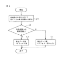
図2に示されたフローチャートは、レーダ制御部内に備えられた制御対象認識部において、物標検出処理が実行されるとき、各ビームに対して検出データ数を設定する手順を現している。先ず、走査機構にスキャンビームの角度を指示したとき、各ビームに係る有効距離Leを算出する(ステップS1)。 The flowchart shown in FIG. 2 shows a procedure for setting the number of detection data for each beam when the target detection process is executed in the control object recognition unit provided in the radar control unit. First, when an angle of the scan beam is instructed to the scanning mechanism, an effective distance Le related to each beam is calculated (step S1).
ここで、車両運転制御システムにおいて、隣接走行レーンを含めた3車線の範囲の物標を検出する必要がある場合には、各ビームのスキャンされる角度と、3車線分の走行レーン幅とから、各ビームに係る有効距離Leを演算できる。例えば、スキャン範囲の端部におけるビームA3については、有効距離Le3が演算され、スキャン角度θの中間におけるビームA2については、有効距離Le2が演算される。 Here, in the vehicle operation control system, when it is necessary to detect a target in the range of three lanes including adjacent driving lanes, the scanning angle of each beam and the driving lane width for three lanes are used. The effective distance Le relating to each beam can be calculated. For example, the effective distance Le3 is calculated for the beam A3 at the end of the scan range, and the effective distance Le2 is calculated for the beam A2 in the middle of the scan angle θ.
次いで、各ビームが放射される毎に、有効距離Leが演算されると、この有効距離Leは、制御距離Lcの大きさと比較される(ステップS2)。ここで、演算された有効距離Leが、制御距離Lcより、例えば、このシステムであれば、100mより大きい場合(ステップS2のY)、当該ビームに対する検出データ数について、デフォルト値を設定する(ステップS3)。このデフォルト値は、10である。これにより、有効距離Leが制御距離Lcより長い範囲のビームによる物標検出に対しては、所定の検出精度が確保される。 Next, when the effective distance Le is calculated every time each beam is emitted, the effective distance Le is compared with the control distance Lc (step S2). Here, when the calculated effective distance Le is greater than 100 m from the control distance Lc, for example, in this system (Y in Step S2), a default value is set for the number of detection data for the beam (Step S2). S3). The default value is 10. Thereby, a predetermined detection accuracy is ensured for target detection using a beam in which the effective distance Le is longer than the control distance Lc.
一方、演算された有効距離Leが、制御距離Lcより、例えば、100mより短い場合(ステップS2のN)、検出データ数のデフォルト値に有効距離Leと制御距離Lcとの比率Le/Lcを乗算して、当該ビームに対する検出ビーム数として、その演算値を設定する(ステップS4)。この場合には、有効距離Leが制御距離Lcより小さい値となっていることから、スキャンされるビームの位置が、スキャン範囲の中央部から見て外側になるほど、設定される検出データ数が、中央部付近のビームに対して設定される検出データ数より減らされることになる。 On the other hand, when the calculated effective distance Le is shorter than the control distance Lc, for example, 100 m (N in Step S2), the default value of the number of detected data is multiplied by the ratio Le / Lc between the effective distance Le and the control distance Lc. Then, the calculated value is set as the number of detected beams for the beam (step S4). In this case, since the effective distance Le is a value smaller than the control distance Lc, the detection data number to be set becomes smaller as the position of the beam to be scanned becomes outside as viewed from the center of the scan range. This is less than the number of detection data set for the beam near the center.
以上のように、直線路を直線走行している場合に関する具体例2によるスキャン型レーダ装置においては、検出精度が要求されるスキャン範囲の中央付近では、所定の検出データ数とし、その外側にあるビームほど、検出データ数を減らすことができるので、レーダ制御部が持つ同じ信号処理時間で、さらに多くの範囲を処理することが可能となる。 As described above, in the scan-type radar apparatus according to the second specific example relating to the case where the vehicle is traveling straight on a straight road, a predetermined number of detection data is set near the center of the scan range where detection accuracy is required, and is outside the predetermined range. Since the number of detected data can be reduced with a beam, a larger number of ranges can be processed in the same signal processing time of the radar control unit.
なお、上述した具体例2のスキャン型レーダ装置では、レーダ制御部において、物標検出処理の際に、スキャンされるビーム毎に有効距離Leを演算して夫々のビームに対する検出データ数をその都度設定したが、車両運転制御システムの車両制御ECUに接続された車速センサとヨーレートセンサとから、車両が直線道路を走行していると判断できるときには、車両が直線走行し続ける限り、各ビームに対する検出データ数の設定を変更する必要がないので、直線走行開始時に演算した有効距離Leを記憶し、直線走行を継続していると判断されるときには、各ビームに対する検出データ数を設定したままとする。 In the scan type radar device of the above-described specific example 2, the radar control unit calculates the effective distance Le for each scanned beam and calculates the number of detected data for each beam in the target detection process. If the vehicle speed sensor and yaw rate sensor connected to the vehicle control ECU of the vehicle operation control system can be determined to be traveling on a straight road, detection is performed for each beam as long as the vehicle continues traveling straight. Since it is not necessary to change the setting of the number of data, the effective distance Le calculated at the start of linear traveling is stored, and when it is determined that the linear traveling is continued, the number of detected data for each beam is kept set. .
以上に説明した具体例1及び2によるスキャン型レーダ装置は、車両が直線走行をしている場合を想定したが、例えば、高速道路など、車両が走行する道路は、直線路だけでなく、カーブしている部分も多い。しかし、具体例1及び2のスキャン型レーダ装置に採用された検出データ数の設定の仕方によって制御したのでは、車両が曲線路を走行しているときには、各ビームがスキャン角度θの範囲内でスキャンされていると、カーブの内側において、物標検出に必要なデータを確保できなくなる。 In the scanning radar apparatus according to the first and second specific examples described above, it is assumed that the vehicle travels in a straight line. However, a road on which the vehicle travels, such as an expressway, is not only a straight road but also a curve. There are many parts. However, when controlled by the method of setting the number of detected data employed in the scanning radar apparatus of specific examples 1 and 2, when the vehicle is traveling on a curved road, each beam is within the range of the scan angle θ. When scanned, it becomes impossible to secure data necessary for target detection inside the curve.
図3に、車両が曲線路を走行しているときの様子が示されている。図3では、実線矢印で示されているように、曲率半径Rの道路上を、スキャン型レーダ装置を搭載したA車が走行しているとする。そこで、該レーダ装置から放射されるビームは、図1の場合と同様に、スキャン角度θの範囲内でスキャンされている。しかし、各ビームは、スキャン角度θでA車の正面に向けて放射されるため、道路がカーブしていると、各ビームの有効距離Leは、道路のカーブの外側部分と内側部分とでは異なるものとなる。 FIG. 3 shows a situation when the vehicle is traveling on a curved road. In FIG. 3, as indicated by the solid line arrow, it is assumed that a vehicle A equipped with a scanning radar device is traveling on a road having a radius of curvature R. Therefore, the beam radiated from the radar apparatus is scanned within the range of the scan angle θ as in the case of FIG. However, since each beam is radiated toward the front of car A at a scan angle θ, when the road is curved, the effective distance Le of each beam differs between the outer portion and the inner portion of the road curve. It will be a thing.
そのため、具体例1及び2によるスキャン型レーダ装置の場合のように、スキャン範囲の端部において、ビームに対する検出データ数を制限してしまうと、車両が曲線路を走行しているときに必要な物標検出データを確保することができなくなる。そこで、具体例3のスキャン型レーダ装置では、曲線路を走行中の場合には、制御距離Lcから抽出数を判定するとき、有効距離Leの演算に、曲線路の曲率半径Rの条件を取り入れて、各ビームのどれが制御距離Lcによる検出に必要かを判断することとした。 For this reason, if the number of detection data for the beam is limited at the end of the scan range as in the case of the scanning radar apparatus according to specific examples 1 and 2, it is necessary when the vehicle is traveling on a curved road. Target detection data cannot be secured. Therefore, in the scan type radar apparatus of the specific example 3, when traveling on a curved road, when determining the number of extraction from the control distance Lc, the condition of the curvature radius R of the curved road is taken into the calculation of the effective distance Le. Thus, it is determined which of the beams is necessary for detection by the control distance Lc.
図4に示されたフローチャートは、車両が曲率半径Rの曲線路をカーブ走行している場合、レーダ制御部内に備えられた制御対象認識部において物標検出処理が実行されるときにおける、各ビームに対して検出データ数を設定する手順を現している。ここで、図4のフローチャートによる手順は、図2に示されたフローチャートの手順を基本としているが、有効距離Leの演算手法の点で、両手順が異なっており、図4の手順では、その演算に、曲率半径Rの条件が加えられており、図2に示されたステップS1がステップS11に置き換えられている。 The flowchart shown in FIG. 4 shows each beam when the target detection processing is executed in the control object recognition unit provided in the radar control unit when the vehicle is traveling along a curved road having a radius of curvature R. Shows the procedure for setting the number of detected data. Here, the procedure according to the flowchart of FIG. 4 is based on the procedure of the flowchart shown in FIG. 2, but both procedures are different in terms of the calculation method of the effective distance Le. In the procedure of FIG. The condition of the radius of curvature R is added to the calculation, and step S1 shown in FIG. 2 is replaced with step S11.
先ず、走査機構にスキャンビームの角度を指示したとき、曲線路の半径Rに応じた各ビームに係る有効距離Leを算出する(ステップS11)。 First, when an angle of the scan beam is instructed to the scanning mechanism, an effective distance Le related to each beam corresponding to the radius R of the curved path is calculated (step S11).
このステップS11における有効距離Leの演算の仕方について、図3を参照して説明する。例えば、制御距離Lcにおいて横方向範囲が3車線に設定されている場合に、最初に、各ビームについて、スキャンされたときの相対横位置が走行レーンの1.5倍の幅に相当する距離を算出する。ここで、スキャン範囲における中心とスキャンされたビームAとの角度をθcとするとき、この角度θcは、次式で求められる。
θc=(Lc/2πR)×180°
なお、車両が走行する曲線路の曲率半径Rについては、A車両の走行速度とヨウレートとから演算によって求めることができる。
A method of calculating the effective distance Le in step S11 will be described with reference to FIG. For example, when the lateral range is set to three lanes at the control distance Lc, first, for each beam, a distance corresponding to a width that is 1.5 times the width of the traveling lane when the relative lateral position is scanned. calculate. Here, when the angle between the center in the scan range and the scanned beam A is θc, the angle θc is obtained by the following equation.
θc = (Lc / 2πR) × 180 °
The curvature radius R of the curved road on which the vehicle travels can be obtained by calculation from the traveling speed and the yaw rate of the vehicle A.
これで、走行している曲線路のカーブに合わせて、ビームのスキャン範囲における横方向位置の中心をづらしたことになり、ビームAの横方向位置が基準となる。次いで、スキャンされる各ビームに対して、当該ビームとこの基準ビームとの角度差から、相対横位置が走行レーンの1.5倍の幅となる距離、即ち、有効距離Leを算出する。ここで、当該ビームのスキャン角度をθとすると、この有効距離Leは、次式で求められる。
Le=1.5×H/sin(|θ−θc|)
Thus, the center of the lateral position in the beam scanning range is set in accordance with the curve of the traveling curved road, and the lateral position of the beam A becomes the reference. Next, for each scanned beam, a distance at which the relative lateral position is 1.5 times the width of the traveling lane, that is, an effective distance Le is calculated from the angle difference between the beam and the reference beam. Here, assuming that the scan angle of the beam is θ, the effective distance Le is obtained by the following equation.
Le = 1.5 × H / sin (| θ−θc |)
そこで、各ビームが放射される毎に、上述の式に従って有効距離Leが演算されるが、これ以降の処理手順は、図2に示されたフローチャートのステップS2乃至ステップS4の処理手順と同様であり、演算された有効距離Leは、制御距離Lcの大きさと比較される(ステップS2)。ここで、演算された有効距離Leが、制御距離Lcより、例えば、このシステムであれば、100mより大きい場合(ステップS2のY)、当該ビームに対する検出データ数について、デフォルト値を設定する(ステップS3)。このデフォルト値は、10である。これにより、有効距離Leが制御距離Lcより長い範囲のビームによる物標検出に対しては、所定の検出精度が確保される。 Therefore, every time each beam is emitted, the effective distance Le is calculated according to the above formula. The subsequent processing procedure is the same as the processing procedure of steps S2 to S4 in the flowchart shown in FIG. Yes, the calculated effective distance Le is compared with the magnitude of the control distance Lc (step S2). Here, when the calculated effective distance Le is greater than 100 m from the control distance Lc, for example, in this system (Y in Step S2), a default value is set for the number of detection data for the beam (Step S2). S3). The default value is 10. Thereby, a predetermined detection accuracy is ensured for target detection using a beam in which the effective distance Le is longer than the control distance Lc.
一方、演算された有効距離Leが、制御距離Lcより、例えば、100mより短い場合(ステップS2のN)、検出データ数のデフォルト値に有効距離Leと制御距離Lcとの比率Le/Lcを乗算して、当該ビームに対する検出ビーム数として、その演算値を設定する(ステップS4)。この場合には、有効距離Leが制御距離Lcより小さい値となっていることから、スキャンされるビームの位置が、スキャン範囲の中央部から見て外側になるほど、設定される検出データ数が、中央部付近のビームに対して設定される検出データ数より減らされることになる。 On the other hand, when the calculated effective distance Le is shorter than the control distance Lc, for example, 100 m (N in Step S2), the default value of the number of detected data is multiplied by the ratio Le / Lc between the effective distance Le and the control distance Lc. Then, the calculated value is set as the number of detected beams for the beam (step S4). In this case, since the effective distance Le is a value smaller than the control distance Lc, the detection data number to be set becomes smaller as the position of the beam to be scanned becomes outside as viewed from the center of the scan range. This is less than the number of detection data set for the beam near the center.
以上の様に、具体例3のスキャン型レーダ装置では、曲線路を走行中の場合においては、制御距離Lcから抽出数を判定するとき、有効距離Leの演算に、曲線路の曲率半径Rの条件が取り入れられて、各ビームのどれが制御距離Lcによる検出に必要かが判断され、そのビームを基準にして検出データ数が設定されるので、曲線路を走行中でも、物標検出に必要な検出データ数を確保でき、同じ信号処理時間で、さらに、精度良く検出範囲を広げることができる。 As described above, in the scan type radar device of the specific example 3, when traveling on a curved road, when determining the number of extractions from the control distance Lc, the effective distance Le is calculated by calculating the curvature radius R of the curved road. Conditions are taken in and it is determined which of each beam is necessary for detection by the control distance Lc, and the number of detection data is set based on that beam. Therefore, even when traveling on a curved road, it is necessary for target detection. The number of detection data can be ensured, and the detection range can be expanded more accurately with the same signal processing time.
これまで説明した具体例1乃至3のスキャン型レーダ装置では、通常の道路を走行している場合を想定したが、スキャン型レーダ装置を搭載した車両が、例えば、トンネルを走行することもある。そこで、具体例4によるスキャン型レーダ装置では、このトンネル内を走行しているときに、反射波がトンネルの影響を受けて、誤って物標検出しないようにするとともに、同じ信号処理時間で、さらに精度よく広角化を図れるようにした。 In the scan type radar devices of specific examples 1 to 3 described so far, it is assumed that the vehicle is traveling on a normal road. However, a vehicle equipped with the scan type radar device may travel through a tunnel, for example. Therefore, in the scanning radar device according to the specific example 4, while traveling in the tunnel, the reflected wave is influenced by the tunnel so as not to detect the target by mistake, and with the same signal processing time, In addition, the wide angle can be improved with high accuracy.
例えば、トンネル内部などでは、走行レーンの両側に、電波を反射する性質を持つ側壁が存在する。そのため、車両がトンネル内部を走行しているときには、スキャン型レーダ装置から放射された送信波ビームがその側壁により反射され、側壁が該レーダ装置によって物標として検出されてしまう。この場合に、側壁からの反射波のレベルが高くなり、単に、レベルの高い検出信号を優先的に抽出するという仕方において、具体例1及び2の場合のように、スキャン範囲の端部におけるビームに対して検出データ数を制限して物標検出が行われると、本来検出されなければならない近距離にある物標に係る検出データを抽出できない可能性がでてくる。 For example, in a tunnel or the like, side walls having a property of reflecting radio waves exist on both sides of a traveling lane. Therefore, when the vehicle is traveling inside the tunnel, the transmission wave beam radiated from the scanning radar apparatus is reflected by the side wall, and the side wall is detected as a target by the radar apparatus. In this case, the level of the reflected wave from the side wall is increased, and the beam at the end of the scan range is simply used in the manner of preferentially extracting a detection signal having a high level, as in the first and second embodiments. However, if target detection is performed by limiting the number of detection data, there is a possibility that detection data relating to a target at a short distance that should be detected cannot be extracted.
そのため、具体例4によるスキャン型レーダ装置では、車両が、トンネルなどのように、側壁を備えた道路を走行している場合に、横方向にスキャンされる各ビームに対して得られる信号情報のうち、他のビームと同じ周波数成分を有するデータを除去して、物標検出を行うようにする。つまり、各ビームを比較して、同じ距離で、同じ相対速度の物標が存在すると判断できる場合に、レーダ装置の走行軸に対して横方向にあるビームデータから、当該物標に係るデータを除去する。 Therefore, in the scanning radar apparatus according to the fourth specific example, when the vehicle is traveling on a road having a side wall such as a tunnel, signal information obtained for each beam scanned in the lateral direction is provided. Of these, data having the same frequency component as that of other beams is removed, and target detection is performed. That is, when each beam is compared and it can be determined that there is a target having the same relative speed at the same distance, the data related to the target is obtained from the beam data lateral to the traveling axis of the radar apparatus. Remove.
以上のようにして、車両がトンネルなどの側壁を有する道路を走行している場合に、物標検出において誤って抽出することがないように、各ビームにおける検出データ数を制限することとした。この検出データ数を制限して設定されることにより、同じ信号処理時間で、さらに精度よく広角化を図れる。なお、具体例4による実施形態を、上述した具体例1又は具体例2による実施形態のスキャン型レーダ装置に適用することもできる。 As described above, when the vehicle is traveling on a road having a side wall such as a tunnel, the number of detected data in each beam is limited so as not to be erroneously extracted in target detection. By setting the number of detection data to be limited, it is possible to widen the angle more accurately with the same signal processing time. Note that the embodiment according to the specific example 4 can also be applied to the scan radar apparatus according to the embodiment according to the specific example 1 or the specific example 2 described above.
1 レーダアンテナ
2 走査機構
3 レーダ制御部
31 走査制御部
32 レーダ信号処理部
33 制御対象認識部
4 車両制御ECU
5 センサ部
5−1 ステアリングセンサ
5−2 ヨーレートセンサ
5−3 車速センサ
6 制御負荷
6−1 表示器
6−2 警報器
6−3 ブレーキ
6−4 スロットル
DESCRIPTION OF
5 Sensor unit 5-1 Steering sensor 5-2 Yaw rate sensor 5-3
Claims (5)
前記送信波ビームのスキャン制御を行い、前記レーダアンテナで受信された受信信号に基づいて前記物標に係る物標情報を生成処理するレーダ制御部とを備え、
前記レーダ制御部は、前記送信波ビームの送信方向に対する横方向範囲におけるビーム位置に応じて、当該ビームに対する抽出すべき信号情報の量を制御して、前記物標情報を生成処理することを特徴とするスキャン型レーダ装置。 A radar antenna mounted on a vehicle, capable of scanning and transmitting a transmission wave beam at a predetermined angle, and receiving a reflected wave reflected from a target in front of the vehicle;
A scan control of the transmission wave beam, and a radar control unit that generates and processes target information related to the target based on a received signal received by the radar antenna,
The radar control unit generates the target information by controlling the amount of signal information to be extracted for the beam according to a beam position in a lateral range with respect to a transmission direction of the transmission wave beam. Scan type radar device.
Priority Applications (1)
| Application Number | Priority Date | Filing Date | Title |
|---|---|---|---|
| JP2004351490A JP2006162341A (en) | 2004-12-03 | 2004-12-03 | Radar system of scanning type |
Applications Claiming Priority (1)
| Application Number | Priority Date | Filing Date | Title |
|---|---|---|---|
| JP2004351490A JP2006162341A (en) | 2004-12-03 | 2004-12-03 | Radar system of scanning type |
Publications (2)
| Publication Number | Publication Date |
|---|---|
| JP2006162341A true JP2006162341A (en) | 2006-06-22 |
| JP2006162341A5 JP2006162341A5 (en) | 2008-01-10 |
Family
ID=36664533
Family Applications (1)
| Application Number | Title | Priority Date | Filing Date |
|---|---|---|---|
| JP2004351490A Pending JP2006162341A (en) | 2004-12-03 | 2004-12-03 | Radar system of scanning type |
Country Status (1)
| Country | Link |
|---|---|
| JP (1) | JP2006162341A (en) |
Cited By (5)
| Publication number | Priority date | Publication date | Assignee | Title |
|---|---|---|---|---|
| JP2008152388A (en) * | 2006-12-14 | 2008-07-03 | Toyota Motor Corp | Periphery-monitoring device for vehicle |
| JP2008170193A (en) * | 2007-01-09 | 2008-07-24 | Mitsubishi Electric Corp | Radar device |
| CN108072873A (en) * | 2016-11-07 | 2018-05-25 | 株式会社万都 | Vehicular object sensor-based system and vehicular object method for sensing |
| US10571563B2 (en) | 2016-06-03 | 2020-02-25 | Fujitsu Ten Limited | Radar device and signal processing method |
| CN111521988A (en) * | 2019-02-01 | 2020-08-11 | 比亚迪股份有限公司 | Radar angle measurement method and device based on beam forming, radar and vehicle |
Citations (4)
| Publication number | Priority date | Publication date | Assignee | Title |
|---|---|---|---|---|
| JPH09292461A (en) * | 1996-04-25 | 1997-11-11 | Matsushita Electric Ind Co Ltd | On-vehicle radar equipment |
| JPH11281735A (en) * | 1998-03-31 | 1999-10-15 | Fujitsu Ten Ltd | Signal processing device for scan type radar |
| JP2002040137A (en) * | 2000-07-26 | 2002-02-06 | Denso Corp | Obstacle-recognizing device for vehicle |
| JP2005127909A (en) * | 2003-10-24 | 2005-05-19 | Fujitsu Ten Ltd | Scanning method of radar |
-
2004
- 2004-12-03 JP JP2004351490A patent/JP2006162341A/en active Pending
Patent Citations (4)
| Publication number | Priority date | Publication date | Assignee | Title |
|---|---|---|---|---|
| JPH09292461A (en) * | 1996-04-25 | 1997-11-11 | Matsushita Electric Ind Co Ltd | On-vehicle radar equipment |
| JPH11281735A (en) * | 1998-03-31 | 1999-10-15 | Fujitsu Ten Ltd | Signal processing device for scan type radar |
| JP2002040137A (en) * | 2000-07-26 | 2002-02-06 | Denso Corp | Obstacle-recognizing device for vehicle |
| JP2005127909A (en) * | 2003-10-24 | 2005-05-19 | Fujitsu Ten Ltd | Scanning method of radar |
Cited By (6)
| Publication number | Priority date | Publication date | Assignee | Title |
|---|---|---|---|---|
| JP2008152388A (en) * | 2006-12-14 | 2008-07-03 | Toyota Motor Corp | Periphery-monitoring device for vehicle |
| JP2008170193A (en) * | 2007-01-09 | 2008-07-24 | Mitsubishi Electric Corp | Radar device |
| US10571563B2 (en) | 2016-06-03 | 2020-02-25 | Fujitsu Ten Limited | Radar device and signal processing method |
| CN108072873A (en) * | 2016-11-07 | 2018-05-25 | 株式会社万都 | Vehicular object sensor-based system and vehicular object method for sensing |
| CN111521988A (en) * | 2019-02-01 | 2020-08-11 | 比亚迪股份有限公司 | Radar angle measurement method and device based on beam forming, radar and vehicle |
| CN111521988B (en) * | 2019-02-01 | 2023-11-14 | 比亚迪股份有限公司 | Radar angle measurement method and device based on beam forming, radar and vehicle |
Similar Documents
| Publication | Publication Date | Title |
|---|---|---|
| US9073548B2 (en) | Vehicle-mounted radar apparatus | |
| US9354299B2 (en) | Radar apparatus and signal processing method | |
| US8976058B2 (en) | Vechicle-mounted radar apparatus | |
| US9134409B2 (en) | Vehicle-mounted radar apparatus | |
| JP4561507B2 (en) | Road shape recognition device | |
| JP4678945B2 (en) | Scanning radar stationary object detection method | |
| JP4007498B2 (en) | Automotive radar equipment | |
| JP6443011B2 (en) | Target detection device | |
| WO2014136718A1 (en) | Object recognition device | |
| JP2009031053A (en) | Device for detecting forward obstacle | |
| JP2010038705A (en) | Signal processing apparatus, radar device, vehicle control device, and signal processing method | |
| JP2014227000A (en) | Vehicle control device, method and program | |
| US8896482B2 (en) | Object detection method | |
| JP2010112937A (en) | Signal processing device and radar device | |
| JP4184096B2 (en) | Preceding vehicle estimation method | |
| JP5983572B2 (en) | Undercover detection device | |
| JP2018115930A (en) | Radar device and method for detecting target | |
| JP2009058316A (en) | Radar device, object detection method, and vehicle | |
| JP2006162341A (en) | Radar system of scanning type | |
| JP4407315B2 (en) | Target estimation device | |
| JP5557491B2 (en) | Signal processing device, radar device, vehicle control system, signal processing method, and program | |
| JP2004286537A (en) | Vehicle-mounted radar equipment | |
| JP2006250793A (en) | Radar apparatus | |
| JP4684876B2 (en) | Radar device and method for detecting object of radar device | |
| JP2001141812A (en) | Fm-cw radar |
Legal Events
| Date | Code | Title | Description |
|---|---|---|---|
| A521 | Written amendment |
Free format text: JAPANESE INTERMEDIATE CODE: A523 Effective date: 20071116 |
|
| A621 | Written request for application examination |
Free format text: JAPANESE INTERMEDIATE CODE: A621 Effective date: 20071116 |
|
| A977 | Report on retrieval |
Free format text: JAPANESE INTERMEDIATE CODE: A971007 Effective date: 20091105 |
|
| A131 | Notification of reasons for refusal |
Free format text: JAPANESE INTERMEDIATE CODE: A131 Effective date: 20091110 |
|
| A521 | Written amendment |
Free format text: JAPANESE INTERMEDIATE CODE: A523 Effective date: 20100104 |
|
| A131 | Notification of reasons for refusal |
Free format text: JAPANESE INTERMEDIATE CODE: A131 Effective date: 20101012 |
|
| A02 | Decision of refusal |
Free format text: JAPANESE INTERMEDIATE CODE: A02 Effective date: 20110308 |