JP2006158633A - Electric pot - Google Patents
Electric pot Download PDFInfo
- Publication number
- JP2006158633A JP2006158633A JP2004354095A JP2004354095A JP2006158633A JP 2006158633 A JP2006158633 A JP 2006158633A JP 2004354095 A JP2004354095 A JP 2004354095A JP 2004354095 A JP2004354095 A JP 2004354095A JP 2006158633 A JP2006158633 A JP 2006158633A
- Authority
- JP
- Japan
- Prior art keywords
- temperature
- hot water
- inner container
- heat
- heat retention
- Prior art date
- Legal status (The legal status is an assumption and is not a legal conclusion. Google has not performed a legal analysis and makes no representation as to the accuracy of the status listed.)
- Pending
Links
Images


Landscapes
- Cookers (AREA)
Abstract
Description
本願発明は、貯湯された湯水を所定の温度で保温する機能をもつ電気ポットに関するものである。 The present invention relates to an electric kettle having a function of keeping stored hot water at a predetermined temperature.
電気ポットは、貯湯用の内容器内の湯水を所定の高温度(たとえば、沸騰状態まで)に加熱したあと、所定の設定温度で保温する機能をそなえているとともに、貯湯容器内の湯水の温度を外部に表示する機能をそなえているものが多い。 The electric kettle has the function of heating the hot water in the inner container for hot water storage to a predetermined high temperature (for example, up to the boiling state) and then keeping it at a predetermined set temperature, and the temperature of the hot water in the hot water storage container. Many of them have a function to display externally.
ところで、このような電気ポットでは内容器の外壁面(多くの場合は底面)に温度センサーを装着して、該温度センサーの検知温度を内容器内の湯温に換算して外部に表示するようにしているのが通例である。この場合、温度センサーが感知する内容器外壁面の温度と内容器内部の実際の湯温とは、ヒーター使用の有無によりある程度異なってくるため、温度センサーの検知温度を貯湯容器内の湯温として表示する場合に、ヒーター使用時の湯温外部表示の数値に対してヒーター不使用時の湯温表示の数値に補正値を加えるようにしたものがある(本件出願人の先願にかかる特開2002−27614=特許文献1)。 By the way, in such an electric pot, a temperature sensor is attached to the outer wall surface (in many cases, the bottom surface) of the inner container, and the temperature detected by the temperature sensor is converted into the hot water temperature in the inner container and displayed outside. It is customary to make it. In this case, the temperature of the outer wall of the inner container sensed by the temperature sensor and the actual hot water temperature inside the inner container differ to some extent depending on whether or not the heater is used. Therefore, the temperature detected by the temperature sensor is used as the hot water temperature in the hot water storage container. In the case of display, there is one in which a correction value is added to the numerical value of the hot water temperature display when the heater is not used with respect to the numerical value of the hot water temperature display when the heater is used (Japanese Patent Application Laid-Open 2002-27614 = Patent Document 1).
ところで、内容器の外壁面に装着した温度センサーの検知温度を内容器内の湯温として表示する場合、上記特許文献1のように、単にヒーターの使用、不使用だけで温度表示の補正を考えれば実用上十分であるかというと、本願発明者の研究によれば、たとえば、ヒーターの使用、不使用にかかわりなく、同じ保温モードの中でも温度表示の補正を行う必要があることが知見された。
By the way, when displaying the detected temperature of the temperature sensor attached to the outer wall surface of the inner container as the hot water temperature in the inner container, it is possible to correct the temperature display only by using or not using the heater as in
また、電気ポットの中には、内容器内の湯水を沸騰させてカルキ抜きしたあと、急速に温度降下させて素早く使用に適した湯温(たとえば、粉ミルク調合用の電気ポットの場合、60℃程度)にするようにしたものがある(いわゆる調乳ポット、等)。そのような電気ポットの場合、湯温を急降下させるために、電気ポットの容器本体内に冷却ファン等の内容器冷却手段を設けて、湯水沸騰後の所定時間だけ、内容器を冷却するようにしたものがある(たとえば、上記実開平4−32629)。 Also, in the electric pot, the hot water in the inner container is boiled to remove the chalk, and then the temperature is rapidly lowered to make it suitable for quick use (for example, 60 ° C. in the case of an electric pot for formulating milk powder). Grade)) (so-called milking pots, etc.). In the case of such an electric pot, in order to rapidly lower the hot water temperature, an inner container cooling means such as a cooling fan is provided in the container body of the electric pot so that the inner container is cooled only for a predetermined time after boiling the hot water. (For example, the above-mentioned Japanese Utility Model Publication No. 4-32629).
このように、同じ保温モードの中で、内容器を冷却する冷却併用保温モードと冷却を伴わないで保温を行う自然放冷保温モードがある場合は、特に、内容器外壁面に装着されている温度センサーと内容器内の実際の湯温との間にそれらの保温モードの相違によってセンサー検知温度に差異が生じることが懸念される。 In this way, in the same heat retention mode, when there is a cooling combined heat retention mode that cools the inner container and a natural cooling and heat retention mode that retains heat without cooling, it is mounted on the outer wall surface of the inner container. There is a concern that a difference in sensor detection temperature may occur between the temperature sensor and the actual hot water temperature in the inner container due to the difference in the heat retention mode.
本願発明は、上記のような知見にもとずいてなされたもので、貯湯用の内容器と、該内容器内の湯水を加熱および保温する保温加熱手段と、上記内容器の外壁面に装着された温度センサーの検知温度を内容器内の湯温として検出する湯温検出手段と、保温時において上記温度センサーの検知温度を内容器内の湯温として演算表示する湯温演算表示手段と、上記内容器内の湯温を異なる保温モードにしたがって所定の目標保温温度に設定する保温モード設定手段と、上記保温加熱手段の出力を制御する保温加熱制御手段とをそなえてなる電気ポットにおいて、上記湯温演算表示手段は、異なる保温モードに対応して上記温度センサーによる検知温度を上記内容器内の湯温として演算する演算式が異なるようにされていることを第1の構成とするものである。 The present invention has been made on the basis of the above-described knowledge, and is mounted on the inner container for hot water storage, heat insulation heating means for heating and keeping hot water in the inner container, and the outer wall surface of the inner container. A hot water temperature detecting means for detecting the detected temperature of the temperature sensor as the hot water temperature in the inner container, and a hot water temperature calculation display means for calculating and displaying the detected temperature of the temperature sensor as the hot water temperature in the inner container at the time of heat retention, In an electric pot comprising: a heat retention mode setting means for setting the hot water temperature in the inner container to a predetermined target heat retention temperature according to different heat retention modes; and a heat retention heating control means for controlling the output of the heat retention heating means. The hot water temperature calculation display means has a first configuration in which an arithmetic expression for calculating the temperature detected by the temperature sensor as the hot water temperature in the inner container is different corresponding to different heat retention modes. Than it is.
また、本願発明は、貯湯用の内容器と、該内容器内の湯水を加熱および保温する保温加熱手段と、上記内容器の湯水の温度が所定の高温度から所定の目標保温温度まで降下するように上記内容器を冷却する内容器冷却手段と、上記内容器の外壁面に装着された温度センサーの検知温度を内容器内の湯温として検出する湯温検出手段と、保温時において上記温度センサーの検知温度を内容器内の湯温として演算表示する湯温演算表示手段と、上記内容器内の湯温を異なる保温モードに対応して所定の目標保温温度に設定する保温モード設定手段と、上記保温加熱手段の出力を制御する保温加熱制御手段とをそなえてなる電気ポットにおいては、上記湯温演算表示手段は、上記内容器が上記内容器冷却手段によって冷却されて所定の高温度から上記目標保温温度まで移行中である保温モード移行時(冷却併用保温モード時)と、上記内容器冷却手段による上記内容器の冷却が行われないで保温される自然放冷保温モード時とで、上記温度センサーによる検知温度を上記内容器内の湯温として演算する演算式が異なるようにされていることを第2の構成とするものである。 The present invention also relates to an inner container for storing hot water, a heat retaining heating means for heating and retaining the hot water in the inner container, and the temperature of the hot water in the inner container drops from a predetermined high temperature to a predetermined target heat retaining temperature. The inner container cooling means for cooling the inner container, the hot water temperature detecting means for detecting the temperature detected by the temperature sensor mounted on the outer wall surface of the inner container as the hot water temperature in the inner container, and the temperature during the heat retention Hot water temperature calculation display means for calculating and displaying the detected temperature of the sensor as the hot water temperature in the inner container; and a heat retention mode setting means for setting the hot water temperature in the inner container to a predetermined target heat retention temperature corresponding to different heat retention modes; In the electric pot provided with the heat insulation heating control means for controlling the output of the heat insulation heating means, the hot water temperature calculation display means is configured such that the inner container is cooled by the inner container cooling means and the predetermined temperature is increased. Up In the heat retention mode transition (during cooling combined heat retention mode) during the transition to the target heat retention temperature and in the natural cooling heat retention mode in which the inner container is not cooled by the inner container cooling means, The second configuration is that the calculation formula for calculating the temperature detected by the temperature sensor as the hot water temperature in the inner container is different.
さらに、本願発明では、上記第2の構成において、内容器冷却手段作動中の湯温降下率が予じめ設定した値に達しない場合に、該内容器冷却手段に異常があるものとしてその異常を報知する内容器冷却手段異常報知手段をそなえることができる(第3の構成)。 Further, in the present invention, in the second configuration, when the rate of temperature drop during operation of the inner container cooling means does not reach a preset value, it is assumed that the inner container cooling means is abnormal. (3rd configuration) can be provided.
本願発明では、また、上記第3の構成において、内容器冷却手段による内容器冷却開始後における所定時間経過後または所定温度到達時までは、上記内容器冷却手段異常報知手段を作動させないようにすることができる(第4の構成)。 In the present invention, in the third configuration, the inner container cooling means abnormality notifying means is not operated after a predetermined time has elapsed after the inner container cooling start by the inner container cooling means or until a predetermined temperature is reached. (Fourth configuration).
本願発明の上記第1の構成のように、貯湯用の内容器と、該内容器内の湯水を加熱および保温する保温加熱手段と、上記内容器の外壁面に装着された温度センサーの検知温度を内容器内の湯温として検出する湯温検出手段と、保温時において上記温度センサーの検知温度を内容器内の湯温として演算表示する湯温演算表示手段と、上記内容器内の湯温を異なる保温モードにしたがって所定の目標保温温度に設定する保温モード設定手段と、上記保温加熱手段の出力を制御する保温加熱制御手段とをそなえてなる電気ポットにおいて、上記湯温演算表示手段が、異なる保温モードに対応して上記温度センサーによる検知温度を上記内容器内の湯温として演算する演算式が異なるようにされていると、保温モードが異なる場合でも温度センサーの各検知温度が、それぞれの保温モードに対応した適切な演算式にしたがって(湯温演算表示手段)によって適切な湯温として表示できる効果がある。 As in the first configuration of the present invention, the inner container for hot water storage, the heat retaining heating means for heating and retaining the hot water in the inner container, and the detection temperature of the temperature sensor mounted on the outer wall surface of the inner container Hot water temperature detecting means for detecting hot water temperature in the inner container, hot water temperature calculation display means for calculating and displaying the detected temperature of the temperature sensor as hot water temperature in the inner container at the time of heat retention, and hot water temperature in the inner container In an electric pot comprising a heat retention mode setting means for setting a predetermined target heat retention temperature according to different heat retention modes and a heat retention heating control means for controlling the output of the heat retention heating means, the hot water temperature calculation display means comprises: If the calculation formula for calculating the temperature detected by the temperature sensor as the hot water temperature in the inner container is different for different heat retention modes, even if the heat retention mode is different, the temperature sensor Detection temperature, according to the appropriate operation expressions corresponding to respective insulation mode by (hot water operation display means) is effective to show a proper water temperature.
また、本願発明の上記第2の構成のように、貯湯用の内容器と、該内容器内の湯水を加熱および保温する保温加熱手段と、上記内容器の湯水の温度が所定の高温度から所定の目標保温温度まで降下するように上記内容器を冷却する内容器冷却手段と、上記内容器の外壁面に装着された温度センサーの検知温度を内容器内の湯温として検出する湯温検出手段と、保温時において上記温度センサーの検知温度を内容器内の湯温として演算表示する湯温演算表示手段と、上記内容器内の湯温を異なる保温モードに対応して所定の目標保温温度に設定する保温モード設定手段と、上記保温加熱手段の出力を制御する保温加熱制御手段とをそなえてなる電気ポットにおいて、上記湯温演算表示手段が、上記内容器が上記内容器冷却手段によって冷却されて所定の高温度から上記目標保温温度まで移行中である保温モード移行時(冷却併用保温モード時)と、上記内容器冷却手段による上記内容器の冷却が行われないで保温される自然放冷保温モード時とで、上記温度センサーによる検知温度を上記内容器内の湯温として演算する演算式が異なるようにされていると、それぞれの保温モードにあわせて、温度センサーによる検知温度をそれぞれの保温モードに対応した演算式によって適切な湯温として湯温演算表示手段によって表示することができる。 Further, as in the second configuration of the present invention, the inner container for hot water storage, the heat retaining heating means for heating and retaining the hot water in the inner container, and the temperature of the hot water in the inner container from a predetermined high temperature. An inner container cooling means for cooling the inner container so as to drop to a predetermined target temperature, and a hot water temperature detection that detects a temperature detected by a temperature sensor mounted on the outer wall surface of the inner container as a hot water temperature in the inner container. Means, a hot water temperature calculation display means for calculating and displaying the temperature detected by the temperature sensor as the hot water temperature in the inner container at the time of heat retention, and a predetermined target heat retaining temperature corresponding to different heat retaining modes for the hot water temperature in the inner container. In the electric pot comprising a heat-retaining mode setting means for setting and a heat-retaining and heating control means for controlling the output of the heat-retaining and heating means, the hot-water temperature calculation display means is configured to cool the inner container by the inner container cooling means. Is When the temperature is changed from a predetermined high temperature to the target temperature, the temperature is kept without the inner container being cooled by the inner container cooling means when the temperature is changed to the heat retention mode (in the cooling combined heat retention mode). If the calculation formula for calculating the temperature detected by the temperature sensor as the hot water temperature in the inner container is different depending on the mode, the temperature detected by the temperature sensor will be kept at the same temperature in accordance with each heat retention mode. An appropriate hot water temperature can be displayed by the hot water temperature calculation display means by an arithmetic expression corresponding to the mode.
さらに、本願発明の上記第3の構成のようにすれば、上記第2の構成において、内容器冷却手段作動中の湯温降下率が予じめ設定した値に達しない場合に、該内容器冷却手段に異常があるものとしてその異常を報知する内容器冷却手段異常報知手段をそなえることができ、その場合は、上記第2の構成の作用に加えて、内容器冷却手段の作動異常を検知することができる。 Further, according to the third configuration of the present invention, in the second configuration, when the rate of temperature drop during operation of the inner container cooling means does not reach a preset value, the inner container It is possible to provide an inner container cooling means abnormality notifying means for notifying that the cooling means is abnormal. In this case, in addition to the operation of the second configuration, the operation abnormality of the inner container cooling means is detected. can do.
また、本願発明の上記第4の構成のようにすれば、上記第3の構成において、内容器冷却手段による内容器冷却開始後における所定時間経過後または所定温度到達時までは、上記内容器冷却手段異常報知手段を作動させないようにすることができ、その場合は、上記第2,第3の構成の作用に加えて、内容器冷却手段の不必要な異常報知によるトラブルを防止し得るという効果がある。 Further, according to the fourth configuration of the present invention, in the third configuration, the inner container cooling is performed after a predetermined time elapses after the inner container cooling start by the inner container cooling means or until a predetermined temperature is reached. In this case, in addition to the operations of the second and third configurations, it is possible to prevent troubles caused by unnecessary abnormality notification of the inner container cooling means. There is.
以下、添付の図面を参照して、本願発明の実施例にかかる電気ポットの構成と作用について説明する。 Hereinafter, the configuration and operation of an electric pot according to an embodiment of the present invention will be described with reference to the accompanying drawings.
(電気ポット本体部の構成)
図1ないし図3には、本願発明の実施例にかかる電気ポットの本体および要部の構成が示されている。
(Configuration of the electric pot body)
1 to 3 show the configuration of the main body and the main part of an electric pot according to an embodiment of the present invention.
この電気ポットは、先ず図1および図2に示すように、貯湯用の内容器3を備えた容器本体1と、該容器本体1の上部側開口部を開閉する蓋体2と、上記内容器3を湯沸し時において加熱する加熱手段である湯沸しヒータ4Aと、上記内容器3を保温時において加熱する加熱手段である保温ヒータ4Bと、上記内容器3内の湯を外部へ給湯するための給湯通路5と、AC電源が接続されている状態において上記給湯通路5を介して上記内容器3内の湯を外部に送り出す電動給湯ポンプ6とを備えて構成されている。
First, as shown in FIGS. 1 and 2, the electric pot includes a
上記容器本体1は、外側面部を構成する合成樹脂製の筒状の外ケース7と、内側面部を構成する上記内容器3と、上記外ケース7と内容器3とを上部側で一体に結合固定する合成樹脂製の環状の肩部材8と、底面部を構成する合成樹脂製の皿状の底部材9とからなっている。
The said container
上記内容器3の底板3aの下面側には、上記湯沸しヒータ4Aと保温ヒータ4B(例えば雲母板にワット数の異なる2組の発熱体を保持させたマイカヒータよりなる)が取り付けられている。
On the lower surface side of the
符号12は、上記内容器3の温度(換言すれば、内容器3内の湯温)を検出する湯温検出手段として作用する温度センサー(湯温センサー又は底センサー)であり、サーミスタよりなっている。さらに、符号13は上記内容器3の満水位を表示する凸状の満水位表示部である。
上記蓋体2は、合成樹脂製の上板14と該上板14に対して外周縁が結合された合成樹脂製の下板15とからなっており、上記肩部材8の後部に設けられたヒンジ受け16に対してヒンジピン17を介して上下方向に開閉自在且つ着脱自在に支持されている。
The
なお、符号21a〜21cは、下方から上方に向けて相互に連通した蓋体2の蒸気排出通路、22は同蒸気排出通路21a〜21cの蒸気導出部21a側途中に配設された転倒時止水弁である。
上記蓋体2における下板15の下面には、金属製の内カバー部材23が固定されており、該内カバー部材23の外周縁には、上記蓋体2の閉蓋時において上記内容器3の給水口3bの上面に圧接される耐熱ラバー製のシールパッキン24が設けられている。
A metal
上記給湯通路5の上流端側である上記内容器3の下部位置には、内容器3側湯導入筒6a、給湯ポンプ側湯吸入口6bを介して直流型の電動給湯ポンプ6が配設されており、この給湯通路5においては上記湯導入筒6aを介して湯吸入口6bより吸入された湯が当該電動給湯ポンプ6のポンピング作用により、その吐出口6cから吐出され、同給湯通路5の湯注出口5aに導かれる。
At the lower position of the
さらに、符号35は、後述する各種スイッチ類の操作面や液晶表示部の表示面を備えた操作パネル部である。
Furthermore, the code |
上記操作パネル部35には、給湯スイッチ38、給湯ロック解除スイッチ39、再沸騰タイマースイッチ40、保温選択スイッチ41、再沸騰表示用LED44、保温動作表示用LED45、給湯ロック解除表示用LED46、液晶表示部47等が設けられている。
The
上記液晶表示部47には、例えば時刻/時間/湯温/作動状態等兼用表示部47a、保温設定温度表示部47b等が設けられており、各種の便利な情報表示がなされるようになっている。
The liquid
この電動給湯型の電気ポットは、上記給湯スイッチ38を押し続ける限り、連続的に上記電動給湯ポンプ6を駆動して湯を注出できる連続給湯モードを備えて構成されている。
The electric hot water supply type electric kettle is configured to have a continuous hot water supply mode in which hot water can be poured out by continuously driving the electric hot water supply pump 6 as long as the hot
図示実施例の電気ポットは、粉ミルク調合用の貯湯ポット(いわゆる、調乳ポット)として機能するように構成されており、容器本体1内の底部ほぼ中央に、内容器内の湯温を所定温度(約60℃)まで急速に降下させるための冷却ファン62とその駆動用モータ61が設置されている。この冷却ファン62は、容器本体1の背面側に形成した空気吸込口26と容器本体1の背面側に形成した空気吸込口27とから空気A1を容器本体1内に吸込み、内容器3の外周面を冷却したあと、同空気を容器本体1の底部に形成された空気排出口28から排気A2として排出する。容器本体1の底部材9の下部には、排気A2の出口となる切欠部29が形成されている。
The electric pot of the illustrated embodiment is configured to function as a hot water storage pot (so-called milking pot) for formulating powdered milk, and the temperature of the hot water in the inner container is set at a predetermined temperature approximately at the center of the bottom of the
(制御回路部の構成)
次に図4は、上記構成の電気ポット本体における制御回路部の構成を示すブロック図である。
(Configuration of control circuit)
Next, FIG. 4 is a block diagram showing the configuration of the control circuit unit in the electric pot body configured as described above.
図4中、符号53は例えば平滑コンデンサおよび電源ICよりなり、マイコン制御部60および加熱制御部54、ポンプ電源部55、ファンモータ電源部63等に直流電源を供給する直流安定化電源部、また54は湯沸しヒータ4Aおよび保温ヒータ4Bの出力制御(ON,OFF制御)用の加熱制御部、4A,4Bは上述した湯沸しヒータ4Aおよび保温ヒータ4Bよりなる加熱手段、55は上記電動給湯ポンプ6のポンプ電源部、38は上述の給湯スイッチ、6は上述の直流型の電動給湯ポンプ、61は冷却ファン62を駆動する冷却ファンモータである。
In FIG. 4,
上記湯沸しヒータ4Aは、例えば上記マイコン制御部60から、上記加熱制御部54に湯沸しヒータON信号が出力されると、例えば図示しないトランジスタを介して電源リレーを作動させ、それに対応して電源スイッチがONになることにより、駆動される。
For example, when the heater control signal is output from the
また、上記保温ヒータ4Bは、上記マイコン制御部60から、上記加熱制御部54に保温ヒータON信号が出力されると、例えば図示しないトランジスタがONになることにより、トライアックを駆動させて駆動される。
Further, when the warming heater ON signal is output from the
また、上記マイコン制御部60には、さらに液晶表示部47、再沸騰表示用LED44、保温動作表示用LED45、給湯ロック解除表示用LED46等の各種LED表示部や給湯スイッチ38、再沸騰タイマースイッチ40、給湯ロック解除スイッチ39、保温選択スイッチ41等の各種操作部や底センサ(サーミスタ)よりなる温度センサー12などの各種センサー部等が、各々図示しない入出力ポートを介して接続されている。
Further, the
そして、以上の電気ポットでは、湯沸時には上記湯沸しヒータ4Aを使用して高加熱出力で速やかに沸とう状態まで加熱した後に、ブザー音による沸とう報知(湯沸し完了報知)を行って湯沸しヒータ4AをOFFにし、その後、保温工程に移行する。
In the above-described electric pot, when the water heater is heated, the
この実施例の電気ポットは、通常の保温機能(95℃又は80℃での湯温維持)のほかに、調乳ポットとしての機能(60℃での湯温維持)を有しており、保温選択スイッチ41の操作により、95℃,80℃又は60℃のいずれかの湯温を選択して保温を行わせることができるようになっている。 The electric pot of this example has a function as a milking pot (maintaining hot water temperature at 60 ° C.) in addition to a normal heat retaining function (maintaining hot water temperature at 95 ° C. or 80 ° C.). By operating the selection switch 41, any hot water temperature of 95 ° C., 80 ° C. or 60 ° C. can be selected and kept warm.
すなわち、この実施例の電気ポットは、内容器を強制冷却する内容器冷却手段(冷却ファン62)を有しており、内容器3内の水を沸騰させてカルキ抜きしたあと、冷却ファン62により内容器3内の湯を急速冷却して調乳に適した湯温(60℃)まで急速降下させることができるようにされている。
That is, the electric pot of this embodiment has an inner container cooling means (cooling fan 62) for forcibly cooling the inner container. After boiling the water in the
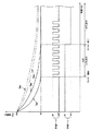
図5は、図示実施例の電気ポットにおける保温工程時の保温ヒータ4Bの制御、冷却ファン62の制御と内容器内の湯温変化ならびに温度センサー12の検知温度の変化とを関連づけて示すグラフである。
FIG. 5 is a graph showing the control of the
図5中、曲線Twoは、内容器3内の水沸騰後にそのまま自然放冷して保温する場合の内容器3内の平均湯温の変化を示す曲線、曲線Tsoは、上記自然放冷保温モード時に温度センサー12が感知する温度変化曲線、曲線Twcは、内容器3内の水沸騰後に冷却ファン62によって内容器3を強制冷却しながら保温する場合の内容器3内の平均湯温の変化を示す温度変化曲線、曲線Tscは上記強制冷却併用保温モード時に温度センサー12が感知する温度変化曲線を示している。
In FIG. 5, a curve Two is a curve showing a change in the average hot water temperature in the
以上からわかるように、自然放冷保温モード時には温度センサー12が感知する温度(センサー検知温度)Tsoと実際の湯温(平均湯温)Twoとの間には、ΔTo=Two−Tsoだけの偏差があり、したがって、自然放冷保温モード時に液晶表示部47において表示する温度(Tno)は、温度センサー12の検知温度Tsoに偏差ΔToを加えた温度(Tno=Tso+ΔTo)とする必要がある。一方、冷却ファン62を駆動しながら行う強制冷却併用保温モード時における温度センサー12のセンサー検知温度Tscと内容器3内の実際の湯温(平均温度)Twcとの間には、ΔTc=Twc−Tscだけの偏差があり、したがって、強制冷却併用保温モード時に液晶表示部47において表示する温度(Tnc)は、温度センサー12の検知温度Tscに偏差ΔTcを加えた温度(Tnc=Tsc+ΔTc)とする必要がある。
As can be seen from the above, there is a deviation of ΔTo = Two−Tso between the temperature (sensor detection temperature) Tso sensed by the
なお、上記の温度偏差(ΔTo,ΔTs)は同じ保温モードの期間中において、常に一定ということはなく、たとえば同じ自然放冷保温モード時であっても、内容器3内の湯量や保温温度帯の変化によって変化する(たとえば、保温温度90℃でのΔTo(90℃)と保温温度60℃でのΔTo(60℃)は同じではない)。
The temperature deviations (ΔTo, ΔTs) are not always constant during the same heat retention mode. For example, even in the same natural cooling and heat retention mode, the amount of hot water in the
以上のように図示実施例の電気ポットでは、自然放冷保温モード時に液晶表示部47に表示する湯温の演算式
Tno=Tso+ΔTo
と、冷却ファン62による強制冷却併用保温モード時に液晶表示部47に表示する湯温の演算式
Tnc=Tsc+ΔTc
とを異ならせている(ΔTo,ΔTcは、予じめ作成して記憶させている演算テーブルから引き出す)。
As described above, in the electric pot of the illustrated embodiment, the hot water temperature calculation expression displayed on the liquid
And an equation for calculating the hot water temperature displayed on the liquid
(ΔTo and ΔTc are extracted from the calculation table stored in advance).
表1は、図示実施例の電気ポットにおいて使用する温度表示用演算テーブルである。 Table 1 is a temperature display calculation table used in the electric pot of the illustrated embodiment.

この表1に示す温度表示用演算テーブルについて説明すると、この実施例の電気ポットでは、温度下降時に、たとえば、自然放冷保温モード時のセンサー検知温度Tsoが63.8℃〜56.2℃、強制冷却併用保温モード時のセンサー検知温度Tscが57.4℃〜53.0℃の場合に、それぞれ液晶表示部47においてTno,Tncが60℃と表示される(※部分)ように、それぞれの保温モードが異なるのにしたがって使用する温度表示用演算テーブルが異なるようにされている。
The temperature display calculation table shown in Table 1 will be described. In the electric pot of this embodiment, when the temperature falls, for example, the sensor detection temperature Tso in the natural cooling and keeping mode is 63.8 ° C. to 56.2 ° C., When the sensor detection temperature Tsc in the forced cooling combined heat retention mode is 57.4 ° C. to 53.0 ° C., Tno and Tnc are displayed as 60 ° C. on the liquid
表1についてさらに詳しく説明すると、この実施例では、液晶表示部47における表示温度(Tno,Tnc)は5℃きざみとされており、それぞれの表示温度に対応するセンサー検知温度の帯域が自然放冷保温モード時と、強制冷却併用保温モード時で異なるようにされている。
Table 1 will be described in more detail. In this embodiment, the display temperatures (Tno, Tnc) in the liquid
すなわち、同じ表示温度に対応するセンサー検知温度の帯域が自然放冷保温モードの方が強制冷却併用保温モードの場合より約1℃〜約5℃高く設定されている(実際には、温度上昇時又は温度降下時に、5℃ごとの表示温度移行のためのそれぞれのセンサー検知温度のしきい値を変化させるだけで対応できる)。 That is, the sensor detection temperature band corresponding to the same display temperature is set to be about 1 ° C. to about 5 ° C. higher in the natural cooling heat retention mode than in the forced cooling combined heat retention mode (actually, when the temperature rises) Or, when the temperature drops, it is possible to respond by simply changing the threshold value of each sensor detection temperature for the display temperature transition every 5 ° C).
次に、図5のグラフ及び図6のフローチャートを使用して図示実施例の電気ポットの制御の態様を説明すると、図示実施例の電気ポットは、給水状態で電源を入れると沸騰モードか否かの判別が行われ(ステップS1)、沸騰モードYESの場合は、表1の温度表示用演算テーブル中の自然放冷保温モード時のセンサー検知温度欄(「通常モード閾値テーブル」という)にしたがって、温度(Tno)の表示が行われ(ステップS2)その表示方法が沸騰検知(ステップS3)まで継続される。 Next, the control mode of the electric pot of the illustrated embodiment will be described using the graph of FIG. 5 and the flowchart of FIG. 6. The electric pot of the illustrated embodiment is in the boiling mode when the power is turned on in the water supply state. (Step S 1 ), and in the case of the boiling mode YES, according to the sensor detection temperature column (referred to as “normal mode threshold value table”) in the natural cooling and keeping mode in the temperature display calculation table of Table 1. The temperature (Tno) is displayed (step S 2 ), and the display method is continued until boiling detection (step S 3 ).
沸騰検知後は、その後の保温工程を冷却ファン62駆動による強制冷却併用保温モード(「冷却モード」という)で行うか、自然放冷保温モード(冷却ファン62非駆動)で行うかの判別が行われ(ステップS4)、冷却モードNOの場合は加熱時と同様、温度表示用演算テーブル中の自然放冷保温モード時のセンサー検知温度Tso欄(「通常モード閾値テーブル」)の数値にしたがって温度Tnoの表示を行いながら、所定の設定温度(たとえば、95℃、80℃)での保温が行われる(保温ヒータ4BのON,OFF制御による:ステップS5,S6)。
After the boiling is detected, it is determined whether the subsequent heat retention process is performed in the forced cooling combined heat retention mode (referred to as “cooling mode”) driven by the cooling
これに対して、ステップS4で冷却モードYESが判別された場合は、以後の温度表示は表1の温度表示用演算テーブル中の強制冷却併用保温モード時のセンサー検知温度Tsc欄(「冷却モード閾値テーブル」という)の数値にしたがって温度Tncの表示を行いながら、所定の設定温度(この実施例では60℃)での保温が行われる。その場合の保温ヒータ4Bや冷却ファン62の制御態様を図5を参照して説明すると、この実施例の電気ポットでは、沸騰検知後、カルキ抜きに必要な時間だけ経過したあと、冷却ファン62を駆動して、内容器3の強制冷却を開始する。その場合は、上記したように、内容器3内の湯温(平均湯温)は図5中の温度曲線Twcのように変化するのに、温度センサー12の検知温度は図5中の温度曲線Tscのように変化する。このため、表1に示す強制冷却併用保温モード時のセンサー検知温度Tscを表示温度Tncとして液晶表示部47に表示する。
In contrast, cooling if the mode YES is determined, the sensor detection temperature Tsc column ( "cooling mode of the subsequent temperature display the forced cooling combined insulation mode in operation table for temperature display in Table 1 at step S 4 While the temperature Tnc is displayed according to the numerical value of the “threshold value table”, the temperature is kept at a predetermined set temperature (60 ° C. in this embodiment). The control mode of the
冷却ファン62による冷却開始後、温度センサー12の検知温度が60℃になったところ(実際の平均湯温は65℃程度)でタイマーを作動させて時間計測を開始し、その後13分間は冷却ファン62と保温ヒータ4Bを併用して温度制御を行うとともに、その間は、液晶表示部47での温度表示は65℃で固定する。
After the start of cooling by the cooling
そしてタイマー作動終了(13分後)になると(そのころ、内容器3内の平均湯温が約60℃になる)冷却ファン62を停止させて保温ヒータ4Bだけでの通常の保温モードに移行する(ステップS9,S5,S6)。そしてそれ以後は、表1の温度表示用演算テーブル中の自然放冷保温モード用のセンサー検知温度Tsoを使用しての温度表示とする。
Then, when the timer operation ends (after 13 minutes) (at that time, the average hot water temperature in the
なお、沸騰モード判定ステップS1でNOの判定がされた場合(すなわち、100℃未満の湯温、たとえば95℃から調乳用の湯温60℃まで急速温度降下させたい場合)は、ステップS7の冷却モードYESへ進み、冷却ファン62が駆動される。その場合の温度表示は、上記したステップS4の冷却モードYESの場合と同様であるので説明を省略する。
When NO is determined in the boiling mode determination step S 1 (that is, when a hot water temperature of less than 100 ° C., for example, when it is desired to rapidly decrease the temperature from 95 ° C. to 60 ° C. for milk preparation), step S The process proceeds to a cooling mode YES of 7 , and the cooling
(図示実施例の電気ポットのその他の構成または変形例)
続いて、図示実施例の電気ポットのその他の構成または変形例を説明する。
(Other configurations or modifications of the electric pot of the illustrated embodiment)
Subsequently, other configurations or modifications of the electric pot of the illustrated embodiment will be described.
(1) 図示実施例の電気ポットでは、冷却ファン62による強制冷却モード時に、温度センサー12で検知する温度の降下率が所定の値を外れた場合に、内容器冷却手段系統に異常があるものとして(たとえば、冷却ファン62それ自体の異常や、冷却空気の吸込口26,27や排気口28の目詰まり等があるものとして)、警報音や、警報ランプ(LED)等で報知する。その場合、異常検知は所定の温度又は時間単位で測定し、複数回異常を検知することによって異常報知するようにすることができる。
(1) In the electric pot of the illustrated embodiment, when the rate of decrease in temperature detected by the
(2) 冷却ファン62による冷却時以外や、冷却ファン62による冷却終了後には、上記異常報知機能が無効となるようにするとよい。
(2) The abnormality notification function may be invalidated except when cooling by the cooling
(3) 図示の実施例において、加熱ヒータ4Aや保温ヒータ4BがONになっていて湯温が上昇しているときと、ヒータ4A,4BがOFFになっていて湯温が降下中であるときとでは、複数種類の異なる通常モード閾値テーブルを使用して液晶表示部47に温度表示させるようにすることができる。
(3) In the illustrated embodiment, when the
(4) 図示実施例の電気ポットにおいて、保温設定温度を変える場合(たとえば95℃保温から80℃保温にする場合など)、当初は従前の閾値テーブルを用いて温度表示し、一定の条件を検知すると(たとえば新たな閾値テーブルにおける特定の閾値とクロスすると)、新たな閾値テーブルに移行して温度表示を行う。 (4) In the electric pot of the illustrated embodiment, when the heat retention set temperature is changed (for example, from 95 ° C. heat retention to 80 ° C. heat retention), the temperature is initially displayed using a conventional threshold table to detect a certain condition. Then (for example, when crossing a specific threshold in the new threshold table), the temperature is displayed by moving to the new threshold table.
(5) 操作パネル部35に静音モード選択ボタンを設けて、該ボタンを押したときは、沸騰報知用ブザー等の各種報知音が出ないようにする(乳幼児の睡眠を妨げないようにするため)。ただし、各種異常警報音は出るようにしておく。なお、静音モードは専用スイッチを設けても良いが、他の操作スイッチを一定時間(3秒程度)同時に押すようにしても良い。
(5) A silent mode selection button is provided on the
(6) 複数の温度設定を有する場合で、静音モードでも、最低温度設定時(たとえば、調乳用湯温である60℃)には設定温度到達報知を行うようにすることができる。 (6) In the case of having a plurality of temperature settings, even in the silent mode, when the minimum temperature is set (for example, 60 ° C., which is the temperature for milk preparation), notification of reaching the set temperature can be performed.
(7) 静音モード時には、ファン冷却モードであってもファンは駆動させないか、または低速駆動に切り替えるようにすることができる。 (7) In the silent mode, the fan is not driven even in the fan cooling mode, or can be switched to low speed driving.
(8) 最低温度設定時(調乳温度設定)時で設定温度への降下途中にロック解除操作が行われた場合にロックは解除されるが、静音モードでもブザー報知を行う。 (8) The lock is released when the unlocking operation is performed during the lowering to the set temperature when the minimum temperature is set (milking temperature setting), but the buzzer is notified even in the silent mode.
(9) 静音モード時にプラグ外れが発生するとブザーで報知し、プラグの再セット後は非静音モードで制御を行うようにすることができる。 (9) When the plug disconnection occurs in the silent mode, a buzzer notifies the user, and the control can be performed in the non-silent mode after the plug is reset.
(10) 静音モードは一回を含む所定回数の湯沸し(沸騰検知)で解除されるようにすることができる。 (10) The silent mode can be canceled by boiling a predetermined number of times (boiling detection) including one time.
(11) 静音モードは給湯又はロック解除の操作で解除されるようにすることができる。 (11) The silent mode can be released by hot water supply or unlocking operation.
(12) 静音モードは手動でも解除されるようにすることができる。 (12) The silent mode can be canceled manually.
(13) 調乳温度設定を最低設定温度として複数の設定温度を有する場合、初期設定は最低設定温度とするとよい。 (13) When there are a plurality of set temperatures with the milk preparation temperature set as the minimum set temperature, the initial setting may be the minimum set temperature.
(14) 調乳用湯温(たとえば60℃)まで冷却している途中の湯吐出注意報知として、設定保温温度として上記湯温(60℃)選択中で、湯温がまだ60℃まで降下していないときにロック解除キーが押されると、ブザー報知(たとえば、「ピ」音 3回)をおこなうようにとともに、ヤケド防止のために湯を吐出禁止とすることができる。あるいは、これとは逆に、ブザー報知は行いつつ、給湯可能状態とすることができる(60℃保温設定時でも、場合によっては高温の湯が使いたいこともあるため)。図7は、この実施態様に対応したフローチャートである。 (14) As a hot water discharge caution notice during cooling to the temperature for preparing milk (for example, 60 ° C.), the hot water temperature (60 ° C.) is being selected as the set heat retention temperature, and the hot water temperature still drops to 60 ° C. When the lock release key is pressed when not in operation, buzzer notification (for example, three “beep” sounds) is performed, and hot water discharge can be prohibited to prevent burns. Or, conversely, it is possible to make a hot water supply possible state while performing a buzzer notification (because it may be desired to use hot water in some cases even at 60 ° C. heat retention setting). FIG. 7 is a flowchart corresponding to this embodiment.
これについて簡単に説明すると、先ず、ステップS1において給湯ロック解除キー39が押されると、60℃保温選択中であるか否かの判別が行われ(ステップS2)、YESであるとステップS3において内容器3内の湯温表示が「65℃」表示以上であるか否かの判別が行われ、YESであると「ピピピ」の警報ブザー音が鳴り(ステップS4)、続いてロック解除LED49が点灯するとともに給湯ロックが解除される(ステップS5,S6)。
If this is briefly described, first, when the hot water supply unlock key 39 in step S 1 is pressed, 60 ° C. incubation whether the selected determination is performed (step S 2), is YES step S In step 3 , it is determined whether or not the hot water temperature display in the
一方、ステップS2又はステップS3においてNOの判定が行われると、単音ブザー音「ピ」が鳴るのみで、そのままステップS5、S6へ進むことができる。 On the other hand, if the determination NO in step S 2 or step S 3 is performed, only single sound buzzer sound "Pi" rings, can be directly proceeds to step S 5, S 6.
(15) 上記(14)の場合に、使用者に直接的に危険状態を知らせるために、ブザー報知にかえて、電動給湯ポンプ6を断続的に作動させて使用者に気付かせることができる。図8は、この実施態様に対応したフローチャートである。 (15) In the case of (14), in order to notify the user of the dangerous state directly, the user can be made aware by operating the electric hot water supply pump 6 intermittently instead of the buzzer notification. FIG. 8 is a flowchart corresponding to this embodiment.
これについて簡単に説明すると、先ずステップS1,S2において保温設定中であるか否か、また60℃保温設定中であるか否かの判別が行われ、それぞれYESであると、内容器3内の水温(湯温)測定が行われ(ステップS3)、さらに湯温が60℃以上であるか否かの判別が行われ(ステップS4)、YESであると続いて給湯ロックを解除するか否か(給湯ロック解除スイッチ39が押されているか否か)の判別が行われる(ステップS5)。そしてステップS5においてYES判別であると給湯可能状態となり、給湯ボタン38を押す(ステップS6=YES)ことにより給湯が開始される。
This will be briefly described. First, in steps S 1 and S 2 , it is determined whether or not the heat retention setting is being performed, and whether or not the heat retention setting is being performed at 60 ° C. The water temperature (hot water temperature) is measured (step S 3 ), and whether or not the hot water temperature is 60 ° C. or higher is determined (step S 4 ). If YES, the hot water supply lock is subsequently released. It is determined whether or not to perform (whether or not the hot water supply
そして、この給湯は以下の制御により継続的に行われることになる。 And this hot water supply is continuously performed by the following control.
すなわち、給湯開始とともにタイマ・カウントが開始され(ステップS7)、そのあと、たとえば5秒ごとに給湯ポンプ6による給湯又は給湯停止が繰り返される(ステップS8,S9,S10,S11,S12)。電気ポットのユーザーは、この異常な湯吐出状態によって危険を察知することができる。この異常な給湯ポンプ動作は、タイマ・クリアされることによって終了する(ステップS13)。 That is, the timer count is started with the start of hot water supply (step S 7 ), and then hot water supply or hot water supply stop by the hot water supply pump 6 is repeated every 5 seconds (steps S 8 , S 9 , S 10 , S 11 , S 12). The user of the electric pot can perceive a danger from this abnormal hot water discharge state. This abnormal hot water supply pump operation ends when the timer is cleared (step S 13 ).
1は容器本体、2は蓋体、3は内容器、4Aは湯沸しヒータ、4Bは保温ヒータ、5は給湯通路、6は電動給湯ポンプ、7は外ケース、8は肩部材、9は底部、12は温度センサー、21a〜21cは蒸気排出通路、26,27は空気吸込口、28は空気排出口、35は操作パネル部、38は給湯スイッチ、39は給湯ロック解除スイッチ、40は再沸騰タイマースイッチ、41は保温選択スイッチ、44は再沸騰表示用LED、45は保温動作表示用LED、46は給湯ロック解除表示用LED、47は液晶表示部、54は加熱制御部、61は駆動用モータ、62は冷却ファンである。
1 is a container body, 2 is a lid, 3 is an inner container, 4A is a hot water heater, 4B is a heat retaining heater, 5 is a hot water supply passage, 6 is an electric hot water supply pump, 7 is an outer case, 8 is a shoulder member, 9 is a bottom, 12 is a temperature sensor, 21a to 21c are steam discharge passages, 26 and 27 are air suction ports, 28 is an air discharge port, 35 is an operation panel section, 38 is a hot water supply switch, 39 is a hot water supply lock release switch, and 40 is a reboiling timer. Switch, 41 is a heat retention selection switch, 44 is a reboiling display LED, 45 is a heat retention operation display LED, 46 is a hot water supply unlock display LED, 47 is a liquid crystal display section, 54 is a heating control section, 61 is a
Claims (4)
Priority Applications (1)
| Application Number | Priority Date | Filing Date | Title |
|---|---|---|---|
| JP2004354095A JP2006158633A (en) | 2004-12-07 | 2004-12-07 | Electric pot |
Applications Claiming Priority (1)
| Application Number | Priority Date | Filing Date | Title |
|---|---|---|---|
| JP2004354095A JP2006158633A (en) | 2004-12-07 | 2004-12-07 | Electric pot |
Related Child Applications (1)
| Application Number | Title | Priority Date | Filing Date |
|---|---|---|---|
| JP2005270226A Division JP2006158951A (en) | 2005-09-16 | 2005-09-16 | Electric pot |
Publications (1)
| Publication Number | Publication Date |
|---|---|
| JP2006158633A true JP2006158633A (en) | 2006-06-22 |
Family
ID=36661261
Family Applications (1)
| Application Number | Title | Priority Date | Filing Date |
|---|---|---|---|
| JP2004354095A Pending JP2006158633A (en) | 2004-12-07 | 2004-12-07 | Electric pot |
Country Status (1)
| Country | Link |
|---|---|
| JP (1) | JP2006158633A (en) |
Cited By (4)
| Publication number | Priority date | Publication date | Assignee | Title |
|---|---|---|---|---|
| JP2012501278A (en) * | 2008-07-21 | 2012-01-19 | ネステク ソシエテ アノニム | Liquid food preparation equipment or beverage preparation equipment with raw material property monitoring |
| CN104566991A (en) * | 2013-09-03 | 2015-04-29 | 广东美的生活电器制造有限公司 | Liquid heating device and control method thereof |
| JP2016022230A (en) * | 2014-07-22 | 2016-02-08 | 株式会社テックスイージー | Milk preparation device |
| CN107198454A (en) * | 2016-06-21 | 2017-09-26 | 九阳股份有限公司 | A kind of cooking apparatus and its method for heating and controlling |
-
2004
- 2004-12-07 JP JP2004354095A patent/JP2006158633A/en active Pending
Cited By (4)
| Publication number | Priority date | Publication date | Assignee | Title |
|---|---|---|---|---|
| JP2012501278A (en) * | 2008-07-21 | 2012-01-19 | ネステク ソシエテ アノニム | Liquid food preparation equipment or beverage preparation equipment with raw material property monitoring |
| CN104566991A (en) * | 2013-09-03 | 2015-04-29 | 广东美的生活电器制造有限公司 | Liquid heating device and control method thereof |
| JP2016022230A (en) * | 2014-07-22 | 2016-02-08 | 株式会社テックスイージー | Milk preparation device |
| CN107198454A (en) * | 2016-06-21 | 2017-09-26 | 九阳股份有限公司 | A kind of cooking apparatus and its method for heating and controlling |
Similar Documents
| Publication | Publication Date | Title |
|---|---|---|
| JP2010172557A (en) | Electric water boiler | |
| JP5147773B2 (en) | Electromagnetic cooker | |
| JP2006158633A (en) | Electric pot | |
| JP2016112099A (en) | Heating cooker | |
| WO2017054214A1 (en) | Pancake machine | |
| JP2006158951A (en) | Electric pot | |
| AU2019100677A4 (en) | Baby mode for a heating vessel | |
| WO2017161680A1 (en) | Method for controlling drink machine | |
| JP3736456B2 (en) | Electric pot | |
| JP2003190017A (en) | Electric pot | |
| JP2006158630A (en) | Electric pot | |
| JP2009066441A (en) | Electric pot | |
| JP2006158727A (en) | Electric pot | |
| JP3177936B2 (en) | Cooking device | |
| JP3617486B2 (en) | an electronic pot | |
| JP4968252B2 (en) | Electric pot | |
| JP4434087B2 (en) | Electric hot water storage container | |
| JP3666470B2 (en) | an electronic pot | |
| JP2007020715A (en) | Electric pot | |
| KR200181864Y1 (en) | A Cold And Hot Water Supplier Having Function of Re-boil | |
| JP4595510B2 (en) | Toilet equipment | |
| JP3928586B2 (en) | Electric pot | |
| JPH08275876A (en) | Pot | |
| JP2023154308A (en) | heating cooker | |
| JP2002243157A5 (en) |
Legal Events
| Date | Code | Title | Description |
|---|---|---|---|
| A621 | Written request for application examination |
Free format text: JAPANESE INTERMEDIATE CODE: A621 Effective date: 20070817 |
|
| A977 | Report on retrieval |
Effective date: 20081014 Free format text: JAPANESE INTERMEDIATE CODE: A971007 |
|
| A131 | Notification of reasons for refusal |
Effective date: 20081021 Free format text: JAPANESE INTERMEDIATE CODE: A131 |
|
| A521 | Written amendment |
Free format text: JAPANESE INTERMEDIATE CODE: A523 Effective date: 20081205 |
|
| A131 | Notification of reasons for refusal |
Free format text: JAPANESE INTERMEDIATE CODE: A131 Effective date: 20090210 |
|
| A02 | Decision of refusal |
Free format text: JAPANESE INTERMEDIATE CODE: A02 Effective date: 20090609 |