JP2006148047A - Modularization radiator - Google Patents
Modularization radiator Download PDFInfo
- Publication number
- JP2006148047A JP2006148047A JP2005156741A JP2005156741A JP2006148047A JP 2006148047 A JP2006148047 A JP 2006148047A JP 2005156741 A JP2005156741 A JP 2005156741A JP 2005156741 A JP2005156741 A JP 2005156741A JP 2006148047 A JP2006148047 A JP 2006148047A
- Authority
- JP
- Japan
- Prior art keywords
- heat
- modular
- pipes
- modules
- heat exchange
- Prior art date
- Legal status (The legal status is an assumption and is not a legal conclusion. Google has not performed a legal analysis and makes no representation as to the accuracy of the status listed.)
- Pending
Links
Images


Classifications
-
- F—MECHANICAL ENGINEERING; LIGHTING; HEATING; WEAPONS; BLASTING
- F28—HEAT EXCHANGE IN GENERAL
- F28F—DETAILS OF HEAT-EXCHANGE AND HEAT-TRANSFER APPARATUS, OF GENERAL APPLICATION
- F28F1/00—Tubular elements; Assemblies of tubular elements
- F28F1/10—Tubular elements and assemblies thereof with means for increasing heat-transfer area, e.g. with fins, with projections, with recesses
- F28F1/12—Tubular elements and assemblies thereof with means for increasing heat-transfer area, e.g. with fins, with projections, with recesses the means being only outside the tubular element
- F28F1/24—Tubular elements and assemblies thereof with means for increasing heat-transfer area, e.g. with fins, with projections, with recesses the means being only outside the tubular element and extending transversely
- F28F1/32—Tubular elements and assemblies thereof with means for increasing heat-transfer area, e.g. with fins, with projections, with recesses the means being only outside the tubular element and extending transversely the means having portions engaging further tubular elements
-
- F—MECHANICAL ENGINEERING; LIGHTING; HEATING; WEAPONS; BLASTING
- F28—HEAT EXCHANGE IN GENERAL
- F28D—HEAT-EXCHANGE APPARATUS, NOT PROVIDED FOR IN ANOTHER SUBCLASS, IN WHICH THE HEAT-EXCHANGE MEDIA DO NOT COME INTO DIRECT CONTACT
- F28D1/00—Heat-exchange apparatus having stationary conduit assemblies for one heat-exchange medium only, the media being in contact with different sides of the conduit wall, in which the other heat-exchange medium is a large body of fluid, e.g. domestic or motor car radiators
- F28D1/02—Heat-exchange apparatus having stationary conduit assemblies for one heat-exchange medium only, the media being in contact with different sides of the conduit wall, in which the other heat-exchange medium is a large body of fluid, e.g. domestic or motor car radiators with heat-exchange conduits immersed in the body of fluid
- F28D1/04—Heat-exchange apparatus having stationary conduit assemblies for one heat-exchange medium only, the media being in contact with different sides of the conduit wall, in which the other heat-exchange medium is a large body of fluid, e.g. domestic or motor car radiators with heat-exchange conduits immersed in the body of fluid with tubular conduits
- F28D1/047—Heat-exchange apparatus having stationary conduit assemblies for one heat-exchange medium only, the media being in contact with different sides of the conduit wall, in which the other heat-exchange medium is a large body of fluid, e.g. domestic or motor car radiators with heat-exchange conduits immersed in the body of fluid with tubular conduits the conduits being bent, e.g. in a serpentine or zig-zag
- F28D1/0477—Heat-exchange apparatus having stationary conduit assemblies for one heat-exchange medium only, the media being in contact with different sides of the conduit wall, in which the other heat-exchange medium is a large body of fluid, e.g. domestic or motor car radiators with heat-exchange conduits immersed in the body of fluid with tubular conduits the conduits being bent, e.g. in a serpentine or zig-zag the conduits being bent in a serpentine or zig-zag
-
- F—MECHANICAL ENGINEERING; LIGHTING; HEATING; WEAPONS; BLASTING
- F28—HEAT EXCHANGE IN GENERAL
- F28F—DETAILS OF HEAT-EXCHANGE AND HEAT-TRANSFER APPARATUS, OF GENERAL APPLICATION
- F28F9/00—Casings; Header boxes; Auxiliary supports for elements; Auxiliary members within casings
- F28F9/26—Arrangements for connecting different sections of heat-exchange elements, e.g. of radiators
- F28F9/262—Arrangements for connecting different sections of heat-exchange elements, e.g. of radiators for radiators
-
- G—PHYSICS
- G06—COMPUTING; CALCULATING OR COUNTING
- G06F—ELECTRIC DIGITAL DATA PROCESSING
- G06F1/00—Details not covered by groups G06F3/00 - G06F13/00 and G06F21/00
- G06F1/16—Constructional details or arrangements
- G06F1/20—Cooling means
-
- F—MECHANICAL ENGINEERING; LIGHTING; HEATING; WEAPONS; BLASTING
- F28—HEAT EXCHANGE IN GENERAL
- F28D—HEAT-EXCHANGE APPARATUS, NOT PROVIDED FOR IN ANOTHER SUBCLASS, IN WHICH THE HEAT-EXCHANGE MEDIA DO NOT COME INTO DIRECT CONTACT
- F28D21/00—Heat-exchange apparatus not covered by any of the groups F28D1/00 - F28D20/00
- F28D2021/0019—Other heat exchangers for particular applications; Heat exchange systems not otherwise provided for
- F28D2021/0028—Other heat exchangers for particular applications; Heat exchange systems not otherwise provided for for cooling heat generating elements, e.g. for cooling electronic components or electric devices
- F28D2021/0031—Radiators for recooling a coolant of cooling systems
-
- H—ELECTRICITY
- H01—ELECTRIC ELEMENTS
- H01L—SEMICONDUCTOR DEVICES NOT COVERED BY CLASS H10
- H01L23/00—Details of semiconductor or other solid state devices
- H01L23/34—Arrangements for cooling, heating, ventilating or temperature compensation ; Temperature sensing arrangements
- H01L23/46—Arrangements for cooling, heating, ventilating or temperature compensation ; Temperature sensing arrangements involving the transfer of heat by flowing fluids
- H01L23/473—Arrangements for cooling, heating, ventilating or temperature compensation ; Temperature sensing arrangements involving the transfer of heat by flowing fluids by flowing liquids
-
- H—ELECTRICITY
- H01—ELECTRIC ELEMENTS
- H01L—SEMICONDUCTOR DEVICES NOT COVERED BY CLASS H10
- H01L2924/00—Indexing scheme for arrangements or methods for connecting or disconnecting semiconductor or solid-state bodies as covered by H01L24/00
- H01L2924/0001—Technical content checked by a classifier
- H01L2924/0002—Not covered by any one of groups H01L24/00, H01L24/00 and H01L2224/00
Landscapes
- Engineering & Computer Science (AREA)
- Physics & Mathematics (AREA)
- General Engineering & Computer Science (AREA)
- Thermal Sciences (AREA)
- Mechanical Engineering (AREA)
- Theoretical Computer Science (AREA)
- Geometry (AREA)
- Human Computer Interaction (AREA)
- General Physics & Mathematics (AREA)
- Cooling Or The Like Of Electrical Apparatus (AREA)
- Cooling Or The Like Of Semiconductors Or Solid State Devices (AREA)
Abstract
Description
本発明は一種の放熱器に係り、特にモジュール化放熱器に関する。 The present invention relates to a kind of radiator, and more particularly to a modular radiator.
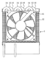
図1は周知の放熱器の後面図であり、図示されるように、伝統的な放熱器1はその熱交換管10が位置をずらした方式で配列され、熱交換管10のファン11の流場を邪魔し、ファン11と放熱器1の間の風の抵抗を大きくし、また、放熱器1の熱交換管10が位置をずらした方式で配列されているため、全体の放熱器1の体積が比較的大きくなる。
FIG. 1 is a rear view of a well-known radiator. As shown in the figure, the traditional radiator 1 has its
図2は周知の液冷式コンピュータ用放熱器の立体図である。図示されるように、液冷式コンピュータ用放熱器1の熱交換管10は一体に放熱フィン12内に固定され、前列と後列の熱交換管10がファン11に接近するか否かにより熱流エリア13とサブ熱流エリア14を形成し、放熱フィン12上で直接の熱伝導を形成し、これにより全体の放熱器1の放熱効率に影響が生じる。このほか、液冷式コンピュータ用放熱器1の熱交換管10は一体に放熱フィン12内に固定されているため、放熱器1の放熱効率は最初から固定され、変化設計と拡充の可能性がなく、理想的とはいえない。
FIG. 2 is a three-dimensional view of a known liquid-cooled computer radiator. As shown in the figure, the
本発明は一種のモジュール化放熱器を提供することを目的とし、それは、相互に前後に一体に配列された少なくとも二つの放熱モジュールを具え、そのうち、各放熱モジュールは複数の放熱フィン、複数の熱交換管、二つの固定板、複数の第一曲管、複数の第二曲管を包含し、その放熱フィンは相互に横向きに平行に配列され、並びに縦向きに相互に特定距離離間し、且つ各放熱フィンに相互に対応する複数の縦向き貫通孔が開設され、熱交換管は相互に平行に並びにそれぞれ縦向きに前述の縦向き貫通孔内を貫通する。 An object of the present invention is to provide a kind of modular heatsink, which includes at least two heatsink modules that are integrally arranged one after the other, each heatsink module having a plurality of heatsink fins, a plurality of heatsinks. Including an exchange pipe, two fixing plates, a plurality of first curved pipes, a plurality of second curved pipes, and the radiating fins are arranged in parallel to each other in the horizontal direction, and are spaced apart from each other by a specific distance, and A plurality of vertical through holes corresponding to each other are formed in each heat dissipating fin, and the heat exchange tubes pass through the above-described vertical through holes in parallel to each other and vertically.
このほか、上述の二つの固定板はそれぞれ平行に放熱フィンの第一縦向き外側及び第二縦向き外側に組み付けられ、且つ二つの固定板に複数の縦向き貫通孔が開設され、それは熱交換管の二端外壁に嵌合され、また複数の第一曲管が第一縦向き外側の二つの隣り合う熱交換管の間に接続され、且つ複数の第二曲管は第二縦向き外側の二つの隣り合う熱交換管の間に接続され、且つ第一曲管は第二曲管と交錯するよう設置され、並びにそれぞれ熱交換管と直列に接続されて連続するS形管路を形成し、各S形管路が入口と出口を包含する。 In addition, the above-mentioned two fixing plates are assembled in parallel to the first vertical outer side and the second vertical outer side of the radiating fin, respectively, and a plurality of vertical through holes are opened in the two fixing plates, which are used for heat exchange. A plurality of first curved pipes are connected between two adjacent heat exchange pipes on the first longitudinally outer side, and the plurality of second curved pipes are on the second longitudinally outer side. Are connected between two adjacent heat exchange pipes, and the first curved pipe is installed so as to intersect with the second curved pipe, and each is connected in series with the heat exchange pipe to form a continuous S-shaped pipe. Each S-shaped conduit includes an inlet and an outlet.
このほか、本発明のモジュール化放熱器は少なくとも一つの連接管を具え、それは上述のそのうち一つの放熱モジュールのS形管路の出口と次の放熱モジュールのS形管路の入口に接続されている。 In addition, the modular heatsink of the present invention includes at least one connecting pipe, which is connected to the outlet of the S-shaped pipe line of one of the above-mentioned heat-dissipating modules and the inlet of the S-shaped pipe line of the next heat-dissipating module. Yes.
本発明は更に少なくとも一つのファンを包含しうる。それは放熱フィンに平行で並びに放熱フィンの特定距離間を流れる流動空気流場を提供する。前述の少なくとも一つのファンは少なくとも二つの放熱モジュール配列後の同一外側、或いは少なくとも二つの放熱モジュールの間に組み付け可能である。 The present invention may further include at least one fan. It provides a flowing air flow field that is parallel to the radiating fins as well as flowing between specific distances of the radiating fins. The at least one fan may be assembled on the same outside after the arrangement of at least two heat dissipation modules or between at least two heat dissipation modules.
このほか、上述の少なくとも二つの放熱モジュールは相互に前後に並列するよう配列され得て、且つ二つの隣り合う固定板の隣り合う内側に固定片が設けられて、並びに相互に一体に組み合わされて固定され、そのうち、二つの隣り合う固定片にそれぞれ固定孔が開設され、並びにネジで二つの固定孔が固定されるか、或いはナットが組み合わされて固定され、或いは固定孔がセルフタッピンネジにより直接固定される。このほか、二つの隣り合う固定片の間に少なくとも一つの断熱パッキングが組み付けられ、これにより熱流エリアとサブ熱流エリアの熱エネルギーが有効に隔離される。 In addition, the at least two heat dissipating modules described above can be arranged in parallel with each other in front and back, and a fixing piece is provided on the inner side of two adjacent fixing plates, and they are integrally combined with each other. The fixing holes are opened in each of two adjacent fixing pieces, and the two fixing holes are fixed with screws, or the nuts are combined and fixed, or the fixing holes are directly fixed with self-tapping screws. Is done. In addition, at least one heat insulating packing is assembled between two adjacent fixed pieces, thereby effectively isolating the heat energy in the heat flow area and the sub heat flow area.
請求項1の発明は、モジュール化放熱器において、
少なくとも二つの放熱モジュールであって、相互に前後に一体に配列され、そのうち、各放熱モジュールは複数の放熱フィン、複数の熱交換管、二つの固定板、複数の第一曲管、複数の第二曲管を包含し、これら放熱フィンは相互に横向きに平行に配列され、並びに縦向きに相互に特定距離離間し、且つ各放熱フィンに相互に対応する複数の縦向き貫通孔が開設され、熱交換管は相互に平行に並びにそれぞれ縦向きに前述の縦向き貫通孔内を貫通し、二つの固定板はそれぞれ平行に放熱フィンの第一縦向き外側及び第二縦向き外側に組み付けられ、該二つの固定板に複数の縦向き貫通孔が開設されて熱交換管の二端外壁に嵌合され、また複数の第一曲管が第一縦向き外側の二つの隣り合う熱交換管の間に接続され、且つ複数の第二曲管は第二縦向き外側の二つの隣り合う熱交換管の間に接続され、且つ第一曲管は第二曲管と交錯するよう設置され、並びにそれぞれ熱交換管と直列に接続されて連続するS形管路を形成し、各S形管路が入口と出口を包含する、上記少なくとも二つの放熱モジュールと、
少なくとも一つの連接管であって、そのうち一つの放熱モジュールのS形管路の出口と次の放熱モジュールのS形管路の入口に接続された、上記少なくとも一つの連接管と、
を包含することを特徴とする、モジュール化放熱器としている。
請求項2の発明は、請求項1記載のモジュール化放熱器において、少なくとも一つのファンを更に具え、それは放熱フィンに平行で並びに放熱フィンの特定距離間を流れる流動空気流場を提供することを特徴とする、モジュール化放熱器としている。
請求項3の発明は、請求項2記載のモジュール化放熱器において、少なくとも一つのファンが少なくとも二つの放熱モジュール配列後の同一外側に組み付けられたことを特徴とする、モジュール化放熱器としている。
請求項4の発明は、請求項2記載のモジュール化放熱器において、少なくとも一つのファンが少なくとも二つの放熱モジュールの間に組み付けられたことを特徴とする、モジュール化放熱器としている。
請求項5の発明は、請求項1記載のモジュール化放熱器において、少なくとも二つの放熱モジュールが相互に前後に並列するよう配列されて、且つ二つの隣り合う固定板の隣り合う内側に固定片が設けられて、並びに固定片が相互に一体に組み合わされて固定されたことを特徴とする、モジュール化放熱器としている。
請求項6の発明は、請求項5記載のモジュール化放熱器において、二つの隣り合う固定片にそれぞれ固定孔が開設され、並びにネジで二つの固定孔が固定されたことを特徴とする、モジュール化放熱器としている。
請求項7の発明は、請求項5記載のモジュール化放熱器において、二つの隣り合う固定片の間に少なくとも一つの断熱パッキングが組み付けられたことを特徴とする、モジュール化放熱器としている。
The invention of claim 1 is a modular radiator,
At least two heat dissipation modules, which are integrally arranged one after the other, each heat dissipation module having a plurality of heat dissipation fins, a plurality of heat exchange tubes, two fixing plates, a plurality of first curved tubes, and a plurality of first Including two bent pipes, these radiating fins are arranged in parallel to each other in the horizontal direction, and a plurality of vertical through holes corresponding to each radiating fin are opened, spaced apart from each other by a specific distance in the vertical direction, The heat exchange tubes pass through the above-described vertical through holes in parallel with each other and in the vertical direction, and the two fixing plates are respectively assembled in parallel with the first vertical outer side and the second vertical outer side of the radiating fins, respectively. A plurality of longitudinal through-holes are formed in the two fixing plates and fitted to the two end outer walls of the heat exchange pipe, and the plurality of first curved pipes are arranged between two adjacent heat exchange pipes on the first longitudinal outer side. And a plurality of second bent pipes are connected between An S-shaped pipe line connected between two adjacent heat exchange pipes on the outer side and the first curved pipe installed so as to intersect with the second curved pipe, and connected in series with each of the heat exchange pipes. And at least two heat dissipating modules each including an inlet and an outlet,
At least one connecting pipe, the at least one connecting pipe connected to the outlet of the S-shaped pipe line of one of the heat dissipating modules and the inlet of the S-shaped pipe line of the next heat dissipating module;
It is set as the modular heatsink characterized by including.
The invention of
According to a third aspect of the present invention, there is provided a modularized heat radiator according to the second aspect, wherein at least one fan is assembled on the same outside after the arrangement of at least two heat radiating modules.
According to a fourth aspect of the present invention, there is provided a modular heat radiator according to the second aspect, wherein at least one fan is assembled between at least two heat radiating modules.
According to a fifth aspect of the present invention, in the modular heatsink according to the first aspect, at least two heat radiating modules are arranged in parallel to each other in the front-rear direction, and a fixing piece is adjacent to the inner side of two adjacent fixing plates. The modular heatsink is characterized in that it is provided and fixed pieces are combined and fixed together.
The invention according to claim 6 is the modular heatsink according to claim 5, wherein a fixing hole is formed in each of two adjacent fixing pieces, and the two fixing holes are fixed by screws. A heatsink is used.
The invention according to claim 7 is the modular heat radiator according to claim 5, wherein at least one heat insulating packing is assembled between two adjacent fixed pieces.
本発明は相互に配列された少なくとも二つの放熱モジュール及び少なくとも一つの連接管により、周知の熱交換管の位置をずらした配列により形成される風の抵抗を防止し、また、全体の放熱器の使用体積を減少する。このほか、放熱モジュールにモジュール化方式の設計が採用され、異なる要求により配列を増加でき、これにより放熱器の変化設計と拡充の可能性が増されている。このほか、モジュール化設計と相互に配列された放熱モジュールにより周知の直接熱伝導の問題を改善でき、全体の放熱器の放熱効率を高めることができる。 The present invention prevents wind resistance formed by an arrangement in which the positions of known heat exchange tubes are shifted by means of at least two heat radiation modules and at least one connecting tube arranged with respect to each other. Reduce the volume used. In addition, a modular design is adopted for the heat dissipation module, and the arrangement can be increased due to different requirements, thereby increasing the possibility of changing and expanding the heatsink. In addition, the well-known problem of direct heat conduction can be improved by the heat dissipation modules arranged mutually with the modular design, and the heat dissipation efficiency of the entire heatsink can be increased.
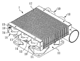
図3、4、5は本発明の好ましい実施例のモジュール化放熱器の正面図、立体図及び平面図である。本実施例中、モジュール化放熱器2は、二つの放熱モジュール3、連接管350、及びファン36を包含する。
3, 4, and 5 are a front view, a three-dimensional view, and a plan view of a modular heatsink according to a preferred embodiment of the present invention. In this embodiment, the
前述の二つの放熱モジュール3は相互に前後に一体に配列され、且つ各放熱モジュール3は複数の放熱フィン30、複数の熱交換管31、二つの固定板32、複数の第一曲管33、複数の第二曲管34を包含する。本実施例中、放熱フィン30は相互に横向きに平行に配列され、並びに縦向きに相互に特定距離離間し、且つ各放熱フィン30に相互に対応する複数の縦向き貫通孔301が開設され、熱交換管31は相互に平行に並びにそれぞれ縦向きに前述の縦向き貫通孔301内を貫通する。
The two
このほか、本実施例においては、上述の二つの固定板32に複数の縦向き貫通孔320が開設され、それは熱交換管31の熱交換管31の二端外壁に嵌合され、且つ第一曲管33は第一縦向き外側302の二つの隣り合う熱交換管31の間に接続され、且つ複数の第二曲管34は第二縦向き外側303の二つの隣り合う熱交換管31の間に接続され、且つ第一曲管33は第二曲管34と交錯するよう設置され、並びにそれぞれ熱交換管31と直列に接続されて連続するS形管路35を形成し、各S形管路35が入口351と出口352を包含する。
In addition, in the present embodiment, a plurality of longitudinal through
このほか、連接管350が図示されるように、そのうち一つの放熱モジュール3のS形管路35の出口352と次の放熱モジュール3のS形管路の入口351に接続されている。
In addition, the connecting
本実施例中、ファン36が二つの放熱モジュール3が平行に重ね合わされた後の同一外側に組み付けられ、それは放熱フィン30に平行で並びに放熱フィン30の特定距離間を流れる流動空気流場360を提供する。
In this embodiment, the
二つの隣り合う固定板32はその隣り合う内側323に固定片321が設けられて、並びに相互に一体に固定され、そのうち、二つの隣り合う固定片321にそれぞれ固定孔322が開設され、並びにネジ37で二つの固定孔322が固定されるか、或いはナットが組み合わされて固定され、或いは固定孔322がセルフタッピンネジにより直接固定される。
The two
また、本実施例は、更に四つの断熱パッキング38を包含し、この四つの断熱パッキング38は二つの隣り合う固定片321の間に組み付けられ、これにより二つの放熱モジュール3の間の熱流エリアとサブ熱流エリアの熱エネルギーが有効に隔離される。
In addition, the present embodiment further includes four
これにより、上述の構造を利用して、周知の熱交換管の位置をずらした配列により形成される風の抵抗を防止し、また、全体のモジュール化放熱器2の使用体積を減少する。このほか、放熱モジュール3にモジュール化方式の設計が採用され、異なる要求により配列を増加でき、これによりモジュール化放熱器2の変化設計と拡充の可能性が増されている。このほか、モジュール化設計と相互に配列された放熱モジュール3により周知の直接熱伝導の問題を改善でき、全体の放熱器の放熱効率を高めることができる。
Thereby, the resistance of the wind formed by the arrangement | positioning which shifted the position of the well-known heat exchange pipe | tube is prevented using the above-mentioned structure, and the use volume of the whole
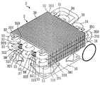
図6は本発明の別の実施例のモジュール化放熱器の分解図である。その主要な構造は上述の実施例と同じであるが、異なるところは、本実施例では四つの放熱モジュール60及び三台のファン61が使用され、放熱モジュール60は直接重ね置かれるほか、相互に前後に所定距離離間するように配列可能で、これにより上述の実施例で説明された各種の効果を達成するほか、ファン61が放熱モジュール60の間に組み付けられて放熱モジュール60の放熱効率が高められている。 FIG. 6 is an exploded view of a modular heat radiator according to another embodiment of the present invention. Its main structure is the same as that of the above-described embodiment, but the difference is that in this embodiment, four heat radiation modules 60 and three fans 61 are used, and the heat radiation modules 60 are directly placed on top of each other. In addition to achieving the various effects described in the above-described embodiments, the fan 61 is assembled between the heat dissipation modules 60 to increase the heat dissipation efficiency of the heat dissipation module 60. It has been.
以上の実施例は本発明の実施範囲を限定するものではなく、本発明に基づきなしうる細部の修飾或いは改変は、いずれも本発明の請求範囲に属するものとする。 The above embodiments do not limit the scope of the present invention, and any modification or alteration of details that can be made based on the present invention shall fall within the scope of the claims of the present invention.
1 放熱器 10 熱交換管
11 ファン 12 放熱フィン
13 熱流エリア 14 サブ熱流エリア
2 モジュール化放熱器 3 放熱モジュール
30 放熱フィン 301 貫通孔
302 第一縦向き外側 303 第二縦向き外側
31 熱交換管 32 固定板
323 内側 33 第一曲管
34 第二曲管 35 S形管路
350 連接管 351 入口
352 出口 36 ファン
360 流動空気流場 37 ネジ
38 断熱パッキング 60 放熱モジュール
61 ファン
DESCRIPTION OF SYMBOLS 1
Claims (7)
少なくとも二つの放熱モジュールであって、相互に前後に一体に配列され、そのうち、各放熱モジュールは複数の放熱フィン、複数の熱交換管、二つの固定板、複数の第一曲管、複数の第二曲管を包含し、これら放熱フィンは相互に横向きに平行に配列され、並びに縦向きに相互に特定距離離間し、且つ各放熱フィンに相互に対応する複数の縦向き貫通孔が開設され、熱交換管は相互に平行に並びにそれぞれ縦向きに前述の縦向き貫通孔内を貫通し、二つの固定板はそれぞれ平行に放熱フィンの第一縦向き外側及び第二縦向き外側に組み付けられ、該二つの固定板に複数の縦向き貫通孔が開設されて熱交換管の二端外壁に嵌合され、また複数の第一曲管が第一縦向き外側の二つの隣り合う熱交換管の間に接続され、且つ複数の第二曲管は第二縦向き外側の二つの隣り合う熱交換管の間に接続され、且つ第一曲管は第二曲管と交錯するよう設置され、並びにそれぞれ熱交換管と直列に接続されて連続するS形管路を形成し、各S形管路が入口と出口を包含する、上記少なくとも二つの放熱モジュールと、
少なくとも一つの連接管であって、そのうち一つの放熱モジュールのS形管路の出口と次の放熱モジュールのS形管路の入口に接続された、上記少なくとも一つの連接管と、
を包含することを特徴とする、モジュール化放熱器。 In modular radiators,
At least two heat dissipation modules, which are integrally arranged one after the other, each heat dissipation module having a plurality of heat dissipation fins, a plurality of heat exchange tubes, two fixing plates, a plurality of first curved tubes, and a plurality of first Including two bent pipes, these radiating fins are arranged in parallel to each other in the horizontal direction, and a plurality of vertical through holes corresponding to each radiating fin are opened, spaced apart from each other by a specific distance in the vertical direction, The heat exchange tubes pass through the above-described vertical through holes in parallel with each other and in the vertical direction, and the two fixing plates are respectively assembled in parallel with the first vertical outer side and the second vertical outer side of the radiating fins, respectively. A plurality of longitudinal through-holes are formed in the two fixing plates and fitted to the two end outer walls of the heat exchange pipe, and the plurality of first curved pipes are arranged between two adjacent heat exchange pipes on the first longitudinal outer side. And a plurality of second bent pipes are connected between An S-shaped pipe line connected between two adjacent heat exchange pipes on the outer side and the first curved pipe installed so as to intersect with the second curved pipe, and connected in series with each of the heat exchange pipes. And at least two heat dissipating modules each including an inlet and an outlet,
At least one connecting pipe, the at least one connecting pipe connected to the outlet of the S-shaped pipe line of one of the heat dissipating modules and the inlet of the S-shaped pipe line of the next heat dissipating module;
A modular heatsink comprising:
6. The modular radiator according to claim 5, wherein at least one heat insulating packing is assembled between two adjacent fixed pieces.
Applications Claiming Priority (1)
| Application Number | Priority Date | Filing Date | Title |
|---|---|---|---|
| TW093218784U TWM267437U (en) | 2004-11-23 | 2004-11-23 | Modular heat dissipation device |
Publications (1)
| Publication Number | Publication Date |
|---|---|
| JP2006148047A true JP2006148047A (en) | 2006-06-08 |
Family
ID=36459890
Family Applications (1)
| Application Number | Title | Priority Date | Filing Date |
|---|---|---|---|
| JP2005156741A Pending JP2006148047A (en) | 2004-11-23 | 2005-05-30 | Modularization radiator |
Country Status (3)
| Country | Link |
|---|---|
| US (1) | US7273092B2 (en) |
| JP (1) | JP2006148047A (en) |
| TW (1) | TWM267437U (en) |
Cited By (34)
| Publication number | Priority date | Publication date | Assignee | Title |
|---|---|---|---|---|
| JP2012054455A (en) * | 2010-09-02 | 2012-03-15 | Fujitsu Ltd | Radiator and electric device |
| JP2013532301A (en) * | 2010-05-04 | 2013-08-15 | マニュファクチャリング・リソーシズ・インターナショナル・インコーポレーテッド | System for cooling an electronic image assembly |
| CN105466243A (en) * | 2015-12-29 | 2016-04-06 | 潍坊恒安散热器集团有限公司 | Novel heat radiator |
| US9549490B2 (en) | 2008-12-18 | 2017-01-17 | Manufacturing Resources International, Inc. | System for cooling an electronic image assembly with circulating gas and ambient gas |
| US9797588B2 (en) | 2008-03-03 | 2017-10-24 | Manufacturing Resources International, Inc. | Expanded heat sink for electronic displays |
| US9801305B2 (en) | 2008-03-03 | 2017-10-24 | Manufacturing Resources International, Inc. | Heat exchanger for an electronic display |
| US9835893B2 (en) | 2008-03-03 | 2017-12-05 | Manufacturing Resources International, Inc. | Heat exchanger for back to back electronics displays |
| US9894800B2 (en) | 2008-03-03 | 2018-02-13 | Manufacturing Resources International, Inc. | Constricted convection cooling system for an electronic display |
| US10080316B2 (en) | 2009-11-13 | 2018-09-18 | Manufacturing Resources International, Inc. | Electronic display assembly having thermal cooling plate and optional convective air cooling loop |
| US10088702B2 (en) | 2013-07-08 | 2018-10-02 | Manufacturing Resources International, Inc. | Figure eight closed loop cooling system for electronic display |
| US10194564B2 (en) | 2014-04-30 | 2019-01-29 | Manufacturing Resources International, Inc. | Back to back electronic display assembly |
| US10212845B2 (en) | 2014-03-11 | 2019-02-19 | Manufacturing Resources International, Inc. | Hybrid rear cover and mounting bracket for electronic display |
| US10278311B2 (en) | 2015-02-17 | 2019-04-30 | Manufacturing Resources International, Inc. | Perimeter ventilation system |
| US10398066B2 (en) | 2017-04-27 | 2019-08-27 | Manufacturing Resources International, Inc. | System and method for preventing display bowing |
| US10420257B2 (en) | 2008-03-26 | 2019-09-17 | Manufacturing Resources International, Inc. | System and method for maintaining a consistent temperature gradient across an electronic display |
| US10485113B2 (en) | 2017-04-27 | 2019-11-19 | Manufacturing Resources International, Inc. | Field serviceable and replaceable display |
| US10524397B2 (en) | 2013-03-15 | 2019-12-31 | Manufacturing Resources International, Inc. | Heat exchanger assembly for an electronic display |
| US10524384B2 (en) | 2013-03-15 | 2019-12-31 | Manufacturing Resources International, Inc. | Cooling assembly for an electronic display |
| US10559965B2 (en) | 2017-09-21 | 2020-02-11 | Manufacturing Resources International, Inc. | Display assembly having multiple charging ports |
| US10660245B2 (en) | 2012-10-16 | 2020-05-19 | Manufacturing Resources International, Inc. | Back pan cooling assembly for electronic display |
| US10795413B1 (en) | 2019-04-03 | 2020-10-06 | Manufacturing Resources International, Inc. | Electronic display assembly with a channel for ambient air in an access panel |
| US10820445B2 (en) | 2016-03-04 | 2020-10-27 | Manufacturing Resources International, Inc. | Cooling system for double sided display assembly |
| US10827656B2 (en) | 2008-12-18 | 2020-11-03 | Manufacturing Resources International, Inc. | System for cooling an electronic image assembly with circulating gas and ambient gas |
| US11019735B2 (en) | 2018-07-30 | 2021-05-25 | Manufacturing Resources International, Inc. | Housing assembly for an integrated display unit |
| US11096317B2 (en) | 2019-02-26 | 2021-08-17 | Manufacturing Resources International, Inc. | Display assembly with loopback cooling |
| US11470749B2 (en) | 2020-10-23 | 2022-10-11 | Manufacturing Resources International, Inc. | Forced air cooling for display assemblies using centrifugal fans |
| US11477923B2 (en) | 2020-10-02 | 2022-10-18 | Manufacturing Resources International, Inc. | Field customizable airflow system for a communications box |
| US11744054B2 (en) | 2021-08-23 | 2023-08-29 | Manufacturing Resources International, Inc. | Fan unit for providing improved airflow within display assemblies |
| US11762231B2 (en) | 2021-08-23 | 2023-09-19 | Manufacturing Resources International, Inc. | Display assemblies inducing turbulent flow |
| US11778757B2 (en) | 2020-10-23 | 2023-10-03 | Manufacturing Resources International, Inc. | Display assemblies incorporating electric vehicle charging equipment |
| US11919393B2 (en) | 2021-08-23 | 2024-03-05 | Manufacturing Resources International, Inc. | Display assemblies inducing relatively turbulent flow and integrating electric vehicle charging equipment |
| US11966263B2 (en) | 2021-07-28 | 2024-04-23 | Manufacturing Resources International, Inc. | Display assemblies for providing compressive forces at electronic display layers |
| US11968813B2 (en) | 2021-11-23 | 2024-04-23 | Manufacturing Resources International, Inc. | Display assembly with divided interior space |
| US12004310B2 (en) | 2022-08-12 | 2024-06-04 | Manufacturing Resources International, Inc. | Display assemblies incorporating electric vehicle charging equipment |
Families Citing this family (16)
| Publication number | Priority date | Publication date | Assignee | Title |
|---|---|---|---|---|
| KR100664076B1 (en) * | 2005-09-29 | 2007-01-03 | 엘지전자 주식회사 | Heat supplying system using fuel cell |
| US7466550B2 (en) * | 2006-11-03 | 2008-12-16 | Xigmatek Co., Ltd | Integrated heat dissipating assembly |
| US9072200B2 (en) * | 2008-09-10 | 2015-06-30 | Schneider Electric It Corporation | Hot aisle containment panel system and method |
| US8184435B2 (en) | 2009-01-28 | 2012-05-22 | American Power Conversion Corporation | Hot aisle containment cooling system and method |
| US8031468B2 (en) * | 2009-06-03 | 2011-10-04 | American Power Conversion Corporation | Hot aisle containment cooling unit and method for cooling |
| TWI394524B (en) * | 2010-02-10 | 2013-04-21 | Delta Electronics Inc | Modularized heat dissipating apparatus |
| EP2663811B1 (en) | 2011-01-11 | 2021-10-06 | Schneider Electric IT Corporation | Cooling unit and method |
| TWI562512B (en) * | 2015-05-20 | 2016-12-11 | Genius Electronic Optical Co Ltd | Water cooling power supply device applicable to open water source |
| GB201609172D0 (en) * | 2016-05-25 | 2016-07-06 | Pierce David B | Heat exchanger unit, assembled heat exchanger and method of installation |
| WO2018044813A1 (en) | 2016-08-31 | 2018-03-08 | Nlight, Inc. | Laser cooling system |
| US20190098799A1 (en) * | 2017-09-26 | 2019-03-28 | Dura Operating, Llc | Thermal enclosure |
| US10784645B2 (en) | 2018-03-12 | 2020-09-22 | Nlight, Inc. | Fiber laser having variably wound optical fiber |
| US11409342B2 (en) * | 2018-10-29 | 2022-08-09 | Corsair Memory, Inc. | Modular PC cooling pump |
| EP3686714A1 (en) | 2019-01-25 | 2020-07-29 | Asetek Danmark A/S | Cooling system including a heat exchanging unit |
| CN111681999A (en) * | 2020-05-18 | 2020-09-18 | 广东工业大学 | Vacuum heat conduction cavity soaking plate and air-cooled heat dissipation device |
| CN114963492B (en) * | 2022-04-12 | 2023-09-22 | 安徽美博新能源科技有限公司 | Modular air conditioner condenser pipe |
Family Cites Families (13)
| Publication number | Priority date | Publication date | Assignee | Title |
|---|---|---|---|---|
| US1788068A (en) * | 1928-12-24 | 1931-01-06 | Mcquay Radiator Corp | Heat-exchange device |
| US1929937A (en) * | 1930-10-01 | 1933-10-10 | Fedders Mfg Co Inc | Evaporator |
| US2047799A (en) * | 1933-08-26 | 1936-07-14 | Justin W Macklin | Air conditioning apparatus |
| US2118206A (en) * | 1935-02-07 | 1938-05-24 | Peerless Of America | Finned type cooling unit |
| US2189652A (en) * | 1937-04-15 | 1940-02-06 | York Ice Machinery Corp | Finned tube |
| US2354131A (en) * | 1938-03-19 | 1944-07-18 | Lul Products Inc | Refrigerating apparatus |
| US3780799A (en) * | 1972-06-26 | 1973-12-25 | Peerless Of America | Heat exchangers and method of making same |
| US4580623A (en) * | 1984-10-02 | 1986-04-08 | Inglis Limited | Heat exchanger |
| US5940270A (en) * | 1998-07-08 | 1999-08-17 | Puckett; John Christopher | Two-phase constant-pressure closed-loop water cooling system for a heat producing device |
| US6263957B1 (en) * | 2000-01-13 | 2001-07-24 | Lucent Technologies Inc. | Integrated active cooling device for board mounted electric components |
| US6926070B2 (en) * | 2002-03-22 | 2005-08-09 | Intel Corporation | System and method for providing cooling systems with heat exchangers |
| US20050099774A1 (en) * | 2003-11-06 | 2005-05-12 | Kyu Sop Song | Semiconductor chip cooling module with fin-fan-fin configuration |
| US7142424B2 (en) * | 2004-04-29 | 2006-11-28 | Hewlett-Packard Development Company, L.P. | Heat exchanger including flow straightening fins |
-
2004
- 2004-11-23 TW TW093218784U patent/TWM267437U/en unknown
-
2005
- 2005-03-25 US US11/088,742 patent/US7273092B2/en not_active Expired - Fee Related
- 2005-05-30 JP JP2005156741A patent/JP2006148047A/en active Pending
Cited By (61)
| Publication number | Priority date | Publication date | Assignee | Title |
|---|---|---|---|---|
| US11013142B2 (en) | 2008-03-03 | 2021-05-18 | Manufacturing Resources International, Inc. | Electronic display with cooling |
| US10721836B2 (en) | 2008-03-03 | 2020-07-21 | Manufacturing Resources International, Inc. | Electronic display with cooling |
| US11540418B2 (en) | 2008-03-03 | 2022-12-27 | Manufacturing Resources International, Inc. | Electronic display with cooling |
| US10506738B2 (en) | 2008-03-03 | 2019-12-10 | Manufacturing Resources International, Inc. | Constricted convection cooling for an electronic display |
| US9797588B2 (en) | 2008-03-03 | 2017-10-24 | Manufacturing Resources International, Inc. | Expanded heat sink for electronic displays |
| US9801305B2 (en) | 2008-03-03 | 2017-10-24 | Manufacturing Resources International, Inc. | Heat exchanger for an electronic display |
| US11596081B2 (en) | 2008-03-03 | 2023-02-28 | Manufacturing Resources International, Inc. | Electronic display with cooling |
| US9894800B2 (en) | 2008-03-03 | 2018-02-13 | Manufacturing Resources International, Inc. | Constricted convection cooling system for an electronic display |
| US9835893B2 (en) | 2008-03-03 | 2017-12-05 | Manufacturing Resources International, Inc. | Heat exchanger for back to back electronics displays |
| US10506740B2 (en) | 2008-03-03 | 2019-12-10 | Manufacturing Resources International, Inc. | Electronic display with cooling |
| US10420257B2 (en) | 2008-03-26 | 2019-09-17 | Manufacturing Resources International, Inc. | System and method for maintaining a consistent temperature gradient across an electronic display |
| US11191193B2 (en) | 2008-12-18 | 2021-11-30 | Manufacturing Resources International, Inc. | System for cooling an electronic image assembly with circulating gas and ambient gas |
| US10827656B2 (en) | 2008-12-18 | 2020-11-03 | Manufacturing Resources International, Inc. | System for cooling an electronic image assembly with circulating gas and ambient gas |
| US10314212B2 (en) | 2008-12-18 | 2019-06-04 | Manufacturing Resources International, Inc. | System for cooling an electronic image assembly with circulating gas and ambient gas |
| US9549490B2 (en) | 2008-12-18 | 2017-01-17 | Manufacturing Resources International, Inc. | System for cooling an electronic image assembly with circulating gas and ambient gas |
| US10736245B2 (en) | 2009-11-13 | 2020-08-04 | Manufacturing Resources International, Inc. | Electronic display assembly with combined conductive and convective cooling |
| US10080316B2 (en) | 2009-11-13 | 2018-09-18 | Manufacturing Resources International, Inc. | Electronic display assembly having thermal cooling plate and optional convective air cooling loop |
| JP2013532301A (en) * | 2010-05-04 | 2013-08-15 | マニュファクチャリング・リソーシズ・インターナショナル・インコーポレーテッド | System for cooling an electronic image assembly |
| JP2012054455A (en) * | 2010-09-02 | 2012-03-15 | Fujitsu Ltd | Radiator and electric device |
| US10660245B2 (en) | 2012-10-16 | 2020-05-19 | Manufacturing Resources International, Inc. | Back pan cooling assembly for electronic display |
| US10524384B2 (en) | 2013-03-15 | 2019-12-31 | Manufacturing Resources International, Inc. | Cooling assembly for an electronic display |
| US10524397B2 (en) | 2013-03-15 | 2019-12-31 | Manufacturing Resources International, Inc. | Heat exchanger assembly for an electronic display |
| US10088702B2 (en) | 2013-07-08 | 2018-10-02 | Manufacturing Resources International, Inc. | Figure eight closed loop cooling system for electronic display |
| US10359659B2 (en) | 2013-07-08 | 2019-07-23 | Manufactruing Resources Internatonal, Inc. | Cooling system for electronic display |
| US10212845B2 (en) | 2014-03-11 | 2019-02-19 | Manufacturing Resources International, Inc. | Hybrid rear cover and mounting bracket for electronic display |
| US10687446B2 (en) | 2014-04-30 | 2020-06-16 | Manufacturing Resources International, Inc. | Back to back electronic display assembly |
| US10973156B2 (en) | 2014-04-30 | 2021-04-06 | Manufacturing Resources International, Inc. | Dual electronic display assembly |
| US10194564B2 (en) | 2014-04-30 | 2019-01-29 | Manufacturing Resources International, Inc. | Back to back electronic display assembly |
| US10278311B2 (en) | 2015-02-17 | 2019-04-30 | Manufacturing Resources International, Inc. | Perimeter ventilation system |
| US10548247B2 (en) | 2015-02-17 | 2020-01-28 | Manufacturing Resources International, Inc. | Perimeter ventilation system |
| CN105466243A (en) * | 2015-12-29 | 2016-04-06 | 潍坊恒安散热器集团有限公司 | Novel heat radiator |
| US10820445B2 (en) | 2016-03-04 | 2020-10-27 | Manufacturing Resources International, Inc. | Cooling system for double sided display assembly |
| US11744036B2 (en) | 2016-03-04 | 2023-08-29 | Manufacturing Resources International, Inc. | Cooling system for double sided display assembly |
| US10716224B2 (en) | 2017-04-27 | 2020-07-14 | Manufacturing Resources International, Inc. | Field serviceable and replaceable assembly |
| US11934054B2 (en) | 2017-04-27 | 2024-03-19 | Manufacturing Resources International, Inc. | Field serviceable and replaceable assembly |
| US10925174B2 (en) | 2017-04-27 | 2021-02-16 | Manufacturing Resources International, Inc. | Field serviceable and replaceable assembly |
| US10757844B2 (en) | 2017-04-27 | 2020-08-25 | Manufacturing Resources International, Inc. | System and method for reducing or combating display bowing |
| US10624218B2 (en) | 2017-04-27 | 2020-04-14 | Manufacturing Resources International, Inc. | Field serviceable and replaceable display assembly |
| US10398066B2 (en) | 2017-04-27 | 2019-08-27 | Manufacturing Resources International, Inc. | System and method for preventing display bowing |
| US11032923B2 (en) | 2017-04-27 | 2021-06-08 | Manufacturing Resources International, Inc. | Field serviceable display assembly |
| US11822171B2 (en) | 2017-04-27 | 2023-11-21 | Manufacturing Resources International, Inc. | Field serviceable and replaceable assembly |
| US10499516B2 (en) | 2017-04-27 | 2019-12-03 | Manufacturing Resources International, Inc. | Field serviceable and replaceable assembly |
| US10485113B2 (en) | 2017-04-27 | 2019-11-19 | Manufacturing Resources International, Inc. | Field serviceable and replaceable display |
| US10559965B2 (en) | 2017-09-21 | 2020-02-11 | Manufacturing Resources International, Inc. | Display assembly having multiple charging ports |
| US11019735B2 (en) | 2018-07-30 | 2021-05-25 | Manufacturing Resources International, Inc. | Housing assembly for an integrated display unit |
| US11889636B2 (en) | 2018-07-30 | 2024-01-30 | Manufacturing Resources International, Inc. | Housing assembly for an integrated display unit |
| US11617287B2 (en) | 2019-02-26 | 2023-03-28 | Manufacturing Resources International, Inc. | Display assembly with loopback cooling |
| US11096317B2 (en) | 2019-02-26 | 2021-08-17 | Manufacturing Resources International, Inc. | Display assembly with loopback cooling |
| US10795413B1 (en) | 2019-04-03 | 2020-10-06 | Manufacturing Resources International, Inc. | Electronic display assembly with a channel for ambient air in an access panel |
| US11507141B2 (en) | 2019-04-03 | 2022-11-22 | Manufacturing Resources International, Inc. | Electronic display assembly with a channel for ambient air in an access panel |
| US11989059B2 (en) | 2019-04-03 | 2024-05-21 | Manufacturing Resources International, Inc. | Electronic display assembly with a channel for ambient air in an access panel |
| US11477923B2 (en) | 2020-10-02 | 2022-10-18 | Manufacturing Resources International, Inc. | Field customizable airflow system for a communications box |
| US11470749B2 (en) | 2020-10-23 | 2022-10-11 | Manufacturing Resources International, Inc. | Forced air cooling for display assemblies using centrifugal fans |
| US11778757B2 (en) | 2020-10-23 | 2023-10-03 | Manufacturing Resources International, Inc. | Display assemblies incorporating electric vehicle charging equipment |
| US11966263B2 (en) | 2021-07-28 | 2024-04-23 | Manufacturing Resources International, Inc. | Display assemblies for providing compressive forces at electronic display layers |
| US11744054B2 (en) | 2021-08-23 | 2023-08-29 | Manufacturing Resources International, Inc. | Fan unit for providing improved airflow within display assemblies |
| US11919393B2 (en) | 2021-08-23 | 2024-03-05 | Manufacturing Resources International, Inc. | Display assemblies inducing relatively turbulent flow and integrating electric vehicle charging equipment |
| US11762231B2 (en) | 2021-08-23 | 2023-09-19 | Manufacturing Resources International, Inc. | Display assemblies inducing turbulent flow |
| US11968813B2 (en) | 2021-11-23 | 2024-04-23 | Manufacturing Resources International, Inc. | Display assembly with divided interior space |
| US12004310B2 (en) | 2022-08-12 | 2024-06-04 | Manufacturing Resources International, Inc. | Display assemblies incorporating electric vehicle charging equipment |
| US12004311B2 (en) | 2023-12-15 | 2024-06-04 | Manufacturing Resources International, Inc. | Housing assembly for an integrated display unit |
Also Published As
| Publication number | Publication date |
|---|---|
| US7273092B2 (en) | 2007-09-25 |
| US20060108105A1 (en) | 2006-05-25 |
| TWM267437U (en) | 2005-06-11 |
Similar Documents
| Publication | Publication Date | Title |
|---|---|---|
| JP2006148047A (en) | Modularization radiator | |
| CN103167780A (en) | Combined type radiator for power module and combined type radiator assembly | |
| JP7152796B2 (en) | water cooling radiator | |
| WO2017036283A1 (en) | Semiconductor refrigerating device for circulation cooling system | |
| US20060090888A1 (en) | Heat-exchange type cooler | |
| US7278467B2 (en) | Liquid-cooled heat radiator kit | |
| CN101431878A (en) | Single plate cooling device and its production method, box type electronic equipment and communication cabinet | |
| JP3125425U (en) | Liquid-cooled heat dissipation device | |
| CN112882983A (en) | Heat dissipation device and server with same | |
| TWI707116B (en) | Liquid cooling device | |
| JP2010093034A (en) | Cooling device for electronic component | |
| CN211352922U (en) | Novel radiator structure for photovoltaic inverter | |
| JP2005051127A (en) | Cooling module and laminated structure of heat radiator | |
| TWM561776U (en) | Water-cooled heat dissipation module | |
| JP3947797B2 (en) | Three-dimensional mounting type heat dissipation module | |
| JP4457238B2 (en) | Heat dissipating structure of heat generating parts in equipment cabinet | |
| JP2005123260A (en) | Water-cooled heatsink | |
| CN106091780B (en) | Fin pitch is from the arc-shaped heat-dissipating pipe that rule changes | |
| CN219876627U (en) | Special-shaped heat dissipation device | |
| CN219328973U (en) | Heat radiation structure and projector | |
| CN214409983U (en) | Heat dissipation device and server with same | |
| CN105180701A (en) | Arc-shaped radiating tube set arranged in corner | |
| CN213694645U (en) | Liquid cooling type heat dissipation device | |
| CN210199679U (en) | Water-cooling radiator with aRGB light efficiency | |
| CN207393310U (en) | A kind of double-radiation function device |
Legal Events
| Date | Code | Title | Description |
|---|---|---|---|
| A977 | Report on retrieval |
Free format text: JAPANESE INTERMEDIATE CODE: A971007 Effective date: 20080716 |
|
| A131 | Notification of reasons for refusal |
Free format text: JAPANESE INTERMEDIATE CODE: A131 Effective date: 20080805 |
|
| A02 | Decision of refusal |
Free format text: JAPANESE INTERMEDIATE CODE: A02 Effective date: 20090303 |