JP2006123631A - Control device of vehicle - Google Patents
Control device of vehicle Download PDFInfo
- Publication number
- JP2006123631A JP2006123631A JP2004312370A JP2004312370A JP2006123631A JP 2006123631 A JP2006123631 A JP 2006123631A JP 2004312370 A JP2004312370 A JP 2004312370A JP 2004312370 A JP2004312370 A JP 2004312370A JP 2006123631 A JP2006123631 A JP 2006123631A
- Authority
- JP
- Japan
- Prior art keywords
- vehicle
- control
- driving force
- deceleration
- control device
- Prior art date
- Legal status (The legal status is an assumption and is not a legal conclusion. Google has not performed a legal analysis and makes no representation as to the accuracy of the status listed.)
- Pending
Links
Images


Landscapes
- Valves And Accessory Devices For Braking Systems (AREA)
- Regulating Braking Force (AREA)
- Control Of Transmission Device (AREA)
Abstract
Description
本発明は、車両の制御装置に係り、特に車両のブレーキ操作検出装置の異常を検出する故障診断装置を備え、車両が、運転者の操作によらず自動減速制御を行う際に、前記故障診断装置の診断を禁止する車両の制御装置に関する。 The present invention relates to a vehicle control device, and more particularly to a failure diagnosis device that detects an abnormality of a vehicle brake operation detection device, and when the vehicle performs automatic deceleration control regardless of a driver's operation, the failure diagnosis is performed. The present invention relates to a vehicle control device that prohibits diagnosis of the device.
従来、運転者のブレーキ操作を直接的に検出するブレーキスイッチを備えた車両における該ブレーキスイッチの故障を診断する装置としては、運転者がブレーキぺダルを踏み込むブレーキ操作と車速センサからの車両速度の減速度(急減速)とを関連づけて、ブレーキスイッチの異常を判定するものがある。この異常検知装置は、運転者がブレーキ操作をしたときにのみ、車両が急減速するという関係を前提としているものであり、車両が急減速しているにも関わらず、ブレーキスイッチからブレーキ操作信号が発せられない(ブレーキスイッチが非動作状態)場合には、ブレーキスイッチが故障状態であると診断するものである(例えば特許文献1参照)。 Conventionally, as a device for diagnosing a failure of a brake switch in a vehicle having a brake switch that directly detects a driver's brake operation, a brake operation in which the driver depresses a brake pedal and a vehicle speed from a vehicle speed sensor are described. There is one that determines an abnormality of a brake switch in association with deceleration (rapid deceleration). This abnormality detection device is premised on the relationship that the vehicle decelerates only when the driver performs a brake operation, and the brake operation signal is output from the brake switch despite the vehicle decelerating rapidly. Is not issued (the brake switch is in a non-operating state), the brake switch is diagnosed as being in a failure state (see, for example, Patent Document 1).
ところで、近年、車両を安定して走行すべく、車両のスリップ状態を検出した時にブレーキ装置を制御するブレーキ制御装置、燃料カットや点火リタードの制御とスロットル開度の制御とにより駆動力を増減させる制御装置、車両の速度や車両の制動を制御する車間距離制御装置、定速度走行制御装置、自動変速機制御装置、トラクションコントロール制御装置などの様々な制御装置が車両に搭載されている。そして、これらの制御装置は、安定走行を行うために、運転者のブレーキ操作によらず、車両の走行条件、外部環境に基づいて車両を自動的に減速させる場合がある。 By the way, in recent years, in order to drive the vehicle stably, a brake control device that controls a brake device when a slip state of the vehicle is detected, a drive force is increased or decreased by control of fuel cut or ignition retard and throttle opening control. Various control devices such as a control device, an inter-vehicle distance control device that controls vehicle speed and vehicle braking, a constant speed travel control device, an automatic transmission control device, and a traction control control device are mounted on the vehicle. And in order to perform stable driving | running | working, these control apparatuses may decelerate a vehicle automatically based on a driving | running condition of a vehicle and an external environment irrespective of a driver | operator's brake operation.
例えば、車間(車両)距離制御装置は、前方車両と衝突の可能性があると判断したときに、運転者がブレーキぺダルを踏まなくても(ブレーキ操作に関係なく)、エンジンに逆駆動力いわゆるエンジンブレーキ状態を要求し、車両を強制的に急減速させる。 For example, when the inter-vehicle (vehicle) distance control device determines that there is a possibility of a collision with the vehicle ahead, even if the driver does not step on the brake pedal (regardless of the brake operation), the reverse driving force is applied to the engine. A so-called engine brake state is requested to forcibly decelerate the vehicle.
しかし、このような制御装置を備えた車両に、先に示した異常検知装置を適用した場合に、前記制御装置は、運転者がブレーキぺダルの操作をしなくても車両を急減速させるものであるため、該異常検知装置は、ブレーキスイッチ(ブレーキ操作検出装置)に異常が無いにも関わらず、ブレーキスイッチが異常であると誤診断をしてしまう。 However, when the above-described abnormality detection device is applied to a vehicle equipped with such a control device, the control device rapidly decelerates the vehicle without operating the brake pedal. Therefore, the abnormality detection device makes a false diagnosis that the brake switch is abnormal although there is no abnormality in the brake switch (brake operation detection device).
さらに、運転者がブレーキペダルを操作したときに、ブレーキスイッチから制御装置に出力されるブレーキ操作信号は、自動制御から手動操作に変更するためのトリガーとして使用されることもあり、例えば、定速度走行(オートクルーズ)制御の解除などに用いられている。しかし、前記の如くブレーキスイッチが異常であると誤診断したときには、ブレーキ操作信号は適切に出力されないため、定速度走行制御などの自動制御を適切に行うことができない。 Furthermore, when the driver operates the brake pedal, the brake operation signal output from the brake switch to the control device may be used as a trigger for changing from automatic control to manual operation. It is used to cancel travel (auto cruise) control. However, when the brake switch is erroneously diagnosed as described above, the brake operation signal is not properly output, so that automatic control such as constant speed traveling control cannot be appropriately performed.
本発明は、このような問題に鑑みてなされたものであって、その目的とするところは、運転者のブレーキ操作によらず車両が自動減速した場合には、ブレーキ操作検出装置の故障の診断を中止して誤診断を防止する車両の制御装置を提供することである。 The present invention has been made in view of such a problem, and an object of the present invention is to diagnose a failure of the brake operation detection device when the vehicle is automatically decelerated regardless of the driver's brake operation. Is to provide a vehicle control device that prevents misdiagnosis.
前記の目的を達成すべく、本発明に係る車両の制御装置は、車両の減速度を検出する減速度検出手段と前記車両の制動装置の制動操作を検出する制動操作検出手段とを有し、前記減速度及び前記制動操作の検出結果に基づいて前記制動操作検出手段の故障を診断する故障診断手段を備えた車両の制御装置であって、該故障診断装置は、前記車両が自動減速制御をしていると判定したときには、前記故障診断を禁止することを特徴としている。 In order to achieve the above object, a vehicle control device according to the present invention has a deceleration detection means for detecting a deceleration of the vehicle, and a braking operation detection means for detecting a braking operation of the braking device of the vehicle, A vehicle control device comprising failure diagnosis means for diagnosing a failure of the braking operation detection means based on the deceleration and the detection result of the braking operation, wherein the failure diagnosis device performs automatic deceleration control. When it is determined that the failure diagnosis is performed, the failure diagnosis is prohibited.
前記の如く構成された本発明の車両の制御装置は、車両が、運転者の手動による制動操作(運転者によるブレーキ踏込み操作)によらない自動減速制御を行ったとしても、自動減速制御をしているときは、故障診断を禁止するので、例えばブレーキスイッチなどの制動操作検出手段が異常であるとの誤診断をすることはない。そして、運転者の制動装置の制動操作によらず、例えば駆動力や制動力を制御して自動減速するような装置が車両に搭載されたとしても、制動操作検出手段の故障診断を正しく行うことができ、制動装置の制動操作に基づいて駆動装置の制御等を確実にすることができる。 The vehicle control device of the present invention configured as described above performs automatic deceleration control even when the vehicle performs automatic deceleration control that does not depend on the driver's manual braking operation (brake stepping operation by the driver). Therefore, the failure diagnosis is prohibited, so that a wrong diagnosis that the braking operation detecting means such as a brake switch is abnormal is not made. And, even if a device that automatically decelerates by controlling the driving force and braking force is mounted on the vehicle, regardless of the braking operation of the driver's braking device, the failure diagnosis of the braking operation detection means is performed correctly. Therefore, the control of the driving device can be ensured based on the braking operation of the braking device.
本発明に係る車両の制御装置は、自動減速制御が、前記車両の定速度走行制御において、前記車両の駆動装置を減速駆動させる制御であることを特徴としている。 The vehicle control device according to the present invention is characterized in that the automatic deceleration control is a control for driving the vehicle drive device to decelerate in the constant speed traveling control of the vehicle.
前記の如く構成された本発明の車両の制御装置は、定速度走行制御において、車両が設定された速度となるように車両を減速すべく、駆動装置(例えばエンジン)の駆動を制御する。そして、このような減速駆動制御をしているときには、自動減速制御をしていると判定し、故障診断を禁止するので、例えばブレーキスイッチなどの制動操作検出手段が異常であるとの誤診断をすることはない。また、制動操作検出手段の診断を正確に行うことで、制動操作検出手段の出力信号をトリガーとした自動制御を、より確実に行うことができる。 The vehicle control device of the present invention configured as described above controls driving of a drive device (for example, an engine) so as to decelerate the vehicle so that the vehicle has a set speed in the constant speed traveling control. When such deceleration drive control is being performed, it is determined that automatic deceleration control is being performed, and failure diagnosis is prohibited. Therefore, for example, an erroneous diagnosis that braking operation detection means such as a brake switch is abnormal is performed. Never do. Further, by accurately diagnosing the braking operation detection means, automatic control using the output signal of the braking operation detection means as a trigger can be performed more reliably.
本発明に係る車両の制御装置は、前記自動減速制御が、前記車両の走行状態に基づいて前記駆動装置を減速駆動させる制御であることを特徴としている。前記の如く構成された本発明の車両の制御装置は、車間距離、車輪のスリップなどの車両の走行状態に基づいて、車両を減速すべく駆動装置を(減速)駆動制御しているときには、車両が自動減速制御をしていると判定し、故障診断を禁止するので、異常であるとの誤診断をすることはない。さらに、制動装置の制動操作(運転者のブレーキ操作)をトリガーとする自動制御を、より精度よく実施することができる。 The vehicle control device according to the present invention is characterized in that the automatic deceleration control is a control for driving the drive device to decelerate based on a running state of the vehicle. The vehicle control device of the present invention configured as described above is configured such that when the drive device (deceleration) drive control is performed in order to decelerate the vehicle based on the traveling state of the vehicle such as the inter-vehicle distance and wheel slip. Is determined to be performing automatic deceleration control, and failure diagnosis is prohibited, so that a false diagnosis of an abnormality is not made. Furthermore, automatic control using a braking operation of the braking device (driver's braking operation) as a trigger can be performed with higher accuracy.
また、本発明に係る車両の制御装置は、前記自動減速制御が、前記制動装置を自動制動させる制御であることを特徴としているので、運転者の制動装置の操作によらず、制御装置が、例えば安全な車両走行すべく制動装置を制御した場合であっても、制動操作検出手段が異常であるとの誤診断をすることはない。 Further, the vehicle control device according to the present invention is characterized in that the automatic deceleration control is control for automatically braking the braking device, so that the control device does not depend on the driver's operation of the braking device, For example, even when the braking device is controlled so that the vehicle travels safely, there is no erroneous diagnosis that the braking operation detection means is abnormal.
また、本発明に係る車両の制御装置は、前記自動減速制御が終了してから、さらに所定時間の間、前記故障診断を禁止することを特徴としている。前記の如く構成された本発明の車両の制御装置は、たとえば、自動減速制御が終了し、車両が制御遅れ等の影響により減速している場合においても、故障診断を禁止しているので制動操作検出手段が異常であると誤診断することはない。 The vehicle control apparatus according to the present invention is characterized in that the failure diagnosis is prohibited for a predetermined time after the automatic deceleration control is completed. The vehicle control apparatus of the present invention configured as described above is, for example, a braking operation because the failure diagnosis is prohibited even when the automatic deceleration control is finished and the vehicle is decelerated due to the influence of a control delay or the like. There is no misdiagnosis that the detection means is abnormal.
また、本発明に係る車両の制御装置は、前記減速度検出手段が、前記車両の速度の変化、又は前記駆動装置の駆動力の変化に基づいて、前記減速度を検出することを特徴としている。前記の如く構成された本発明の車両の制御装置は、駆動力の変化に基づいて減速度を検出するので、制動操作検出手段の異常を、より正確に検出することができる。また、好ましくは、前記減速度を加速度計等により検出してもよい。 Further, the vehicle control apparatus according to the present invention is characterized in that the deceleration detection means detects the deceleration based on a change in the speed of the vehicle or a change in the driving force of the drive device. . Since the vehicle control device of the present invention configured as described above detects the deceleration based on the change in the driving force, it is possible to detect the abnormality of the braking operation detecting means more accurately. Preferably, the deceleration may be detected by an accelerometer or the like.
さらにまた、本発明に係る車両の制御装置における前記減速駆動させる制御をしていることの判定は、前記制御装置が前記駆動装置に要求する駆動力に基づいて行われることを特徴とする。 Still further, the determination that the control for the deceleration drive is performed in the vehicle control device according to the present invention is performed based on a driving force required by the control device for the drive device.
本発明によれば、運転者がブレーキを操作せずに、車両が自動的に減速した場合に、ブレーキスイッチなどの制動操作検出手段の故障診断を禁止するので、誤った診断をすることがない。さらに、このような誤診断を防止することで、制動装置の制動操作(運転者のブレーキ操作)信号をトリガーとして自動制御を行うような制御装置を安定して使用することができる。 According to the present invention, when the vehicle is automatically decelerated without operating the brake, the failure diagnosis of the brake operation detecting means such as the brake switch is prohibited, so that no erroneous diagnosis is made. . Furthermore, by preventing such a misdiagnosis, it is possible to stably use a control device that performs automatic control using a brake operation (driver's brake operation) signal as a trigger.
以下、本発明に係る車両の制御装置の一実施形態を図面に基づき詳細に説明する。 Hereinafter, an embodiment of a vehicle control apparatus according to the present invention will be described in detail with reference to the drawings.
図1は本実施形態に係る車両の制御装置10を備えた車両1の全体構成図を示した図である。
FIG. 1 is a diagram showing an overall configuration diagram of a
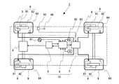
図1に示すように、車両1は、エンジン本体(駆動装置)4、制動装置(ブレーキ)8、車輪9、及び車両の制御装置10を備えている。そして、車両の制御装置10は、エンジン制御装置(ECU)5、車両安定化制御装置(ESP)6、制動制御装置7を備えており、エンジン制御装置5は、運転者の運転操作による操作信号及び後述する車両安定化制御装置6からの出力信号に基づいて、エンジン本体4を制御しており、該エンジン本体4は、エンジン制御装置5の制御信号に基づいて車輪(駆動輪)9に駆動力を伝達している。
As shown in FIG. 1, the
一方、制動制御装置7は、主にキャリパー81及びブレーキディスク82からなる制動装置8を制御し、前記駆動回転した車輪9を制動し、車両1を減速させる装置であって、運転者のブレーキぺダル49の踏込み量(操作量)または後述する車両安定化制御装置6からの出力信号に基づいて、キャリパー81に油を供給してブレーキパッド(図示せず)をブレーキディスク82に押圧し制動制御を行っている。また、ブレーキぺダル49が手動により制動操作をしたときには、その制動操作を検出するために、ブレーキ操作検出装置50が作動する(ON状態となる)。
On the other hand, the
また、この他にも、車両1には、車両1の状態を検出するために、例えば、ステアリングの角度を検出するステアリング角度センサ61、車両1のヨーレイトを検出するヨーレイトセンサ62、横方向に作用する加速度を検出する横Gセンサ63、車両1の4つの車輪9の車輪速度を検出する車輪速度センサ64、が配置されている。
In addition, in order to detect the state of the
車両安定化制御装置(ESP)6は、車両の走行状態に基づいて車輪9に伝達される駆動力を制御することで、車両1を安定走行させる装置であり、先に示したステアリング角度センサ61、ヨーレイトセンサ62、横Gセンサ63、車輪速度センサ64、からの信号に基づいて、車両1を安定走行させるための条件を、内蔵したマイクロコンピュータで演算し、前記エンジン制御装置5と、制動制御装置7と、に信号を出力している。
The vehicle stabilization control device (ESP) 6 is a device for stably driving the
具体的には、車両安定化制御装置6は、前記ステアリング角度センサ61、ヨーレイトセンサ62、横Gセンサ63、車輪速度センサ64での検出信号に基づいて、駆動輪9の空転や車両1の横滑り等を検知した場合に、制動制御装置7に制動要求信号を出力すると共に、駆動力の増減を図るために、エンジン制御装置5に駆動力の増減を要求する信号を出力する。
Specifically, the vehicle
そして、車両安定化制御装置6から制動要求信号を受けた制動制御装置7は、4輪のブレーキ8を個々に制御する。一方、車両安定化制御装置6から駆動力増減の要求信号を受けたエンジン制御装置5は、車両を安定化する要求(主に駆動力の増減の要求)を満たすため、燃料供給量や点火時期、スロットル開度等を制御し、駆動輪9の空転や車両1の横滑り等を回避する。
Then, the
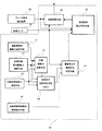
図2は、エンジン制御装置5、車両安定化制御装置6、これらの装置に接続された機器、及び入出力される信号を説明するための制御ブロック図である。図2に示すように車両安定化制御装置6は、前記ステアリング角度センサ61、ヨーレイトセンサ62、横Gセンサ63、車輪速度センサ64に接続され、これらセンサ61〜64で検出された検出信号が入力可能となっている。そして、車両安定化制御装置6は、これらのセンサ検出信号と、エンジン制御装置5からの出力信号と、に基づいて、スリップや横滑りの可能性がある場合には車両の目標駆動力を演算するとともに4つ車輪の各々に対して、制動制御時にかけるべきブレーキ圧を演算し、車輪ブレーキ圧を制御するための信号を制動制御装置7に送信する。
FIG. 2 is a control block diagram for explaining the
一方、エンジン制御装置5は、前記ブレーキ操作検出装置50と、車両の速度を検出する車速センサ51と、運転者のアクセル操作量を検出するアクセルペダルセンサ52と、エンジンの回転数を計測するクランク角度センサ53と、定速度走行制御(定速制御)を起動するためのクルーズメインスイッチ54と、定速度走行制御中に車両速度を増加するためのクルーズ加速スイッチ55と、定速度走行制御中に車両速度を減少するためクルーズ減速スイッチ56と、ギアまたはブレーキの操作で一時的に定速度走行制御がキャンセルされてから再度定速度走行制御を起動するためクルーズレジュームスイッチ57と、に接続されており、これらのセンサまたはスイッチの信号が入力可能な状態となっている。
On the other hand, the
そして、エンジン制御装置5は、車両の安定化要求、主に駆動力の増減の要求を満たすために、空気量を調節する電子スロットル装置41と、燃料供給量を調節する燃料噴射装置42と、点火時期を調節する点火装置43と、運転者のブレーキ操作を示すブレーキランプ44とに、制御信号を出力すべく接続されている。また、車両安定化制御装置6とエンジン制御装置5とは、CAN通信による通信手段を介して通信可能に接続されている。
The
図3は、図2に示す車両安定化制御装置6とエンジン制御装置5との間のCAN通信情報を説明するためのブロック図である。図3に示すように、エンジン制御装置5は、エンジンの燃焼における燃焼トルク、後述する運転者の操作(要求)により演算された運転者要求駆動力、エンジン本体4の機械的損失やポンプ損失によるエンジンフリクショントルクを車両安定化制御装置6へ送信する。
FIG. 3 is a block diagram for explaining CAN communication information between the vehicle
一方、車両安定化制御装置6は、車両の走行状態を検出する各センサ61〜64に基づいて該装置で演算した外部要求駆動力と、ブレーキぺダルの制動操作によらず自動制動すべく制動制御装置7に出力した自動制動制御動作情報をエンジン制御装置5へ送信する。ここに示す外部要求駆動力は、車両を安定走行させるために運転者の直接的な操作とは関係なく、外部から間接的にエンジン本体4を制御させるための駆動力であり、具体的に車両の駆動力を増減させる要求が含まれている。また、この外部要求駆動力としては、車両の駆動力の増減ではなく、エンジン燃焼トルク増減など、駆動力の増減を示すものであるならば特に限定されない。
On the other hand, the vehicle
図4は、本実施形態に係る車両の制御装置10の全体の制御ブロック図を示している。図4に示すように、制御装置10は、ブレーキ操作検出装置(ブレーキスイッチ)50の故障を診断するため故障診断手段20を備えている。該故障診断手段20は、車速センサ51の車速信号から車両の減速度を検出する減速度検出手段(図示せず)とブレーキ操作検出装置50で検出した操作信号から制動操作を検出する制動操作検出手段(図示せず)とを備え、検出した減速度及び制動操作の各々の結果に基づいて、ブレーキ操作検出装置50の故障を診断している。
FIG. 4 is an overall control block diagram of the
また、制御装置10は、運転者以外減速要求判定手段(自動減速判定手段)17、故障診断禁止判定手段18、運転者要求駆動力演算手段11、定速制御要求駆動力演算手段12、外部要求駆動力演算手段13、自動制動制御動作情報検出手段14、目標駆動力演算手段15、及び車両走行状態判定手段16、を備えている。以下に示す各要求駆動力とは、エンジン本体4に要求する駆動力そのものであってもよいが、駆動力に比例した要求量であってもよい。
Further, the
運転者要求駆動力演算手段11は、運転者がエンジン本体4に要求する要求駆動力を演算し、定速制御要求駆動力演算手段12は、車両を定速度で走行させるべくエンジン本体4に要求する要求駆動力を演算し、外部要求駆動力演算手段13は、車両を安定走行すべく車両の走行状態に基づいてエンジン本体4に要求する要求駆動力を演算している。そして、これらの演算手段で演算された要求駆動力は、目標駆動力演算手段15へ出力され、目標駆動力演算手段15は、これらの3つの要求駆動力に基づいて、エンジン本体4が駆動すべき目標駆動力を演算している。ここで示す目標駆動力とは、エンジン本体4を駆動させるための目標となる駆動力そのものであるが、先に示したように、駆動力に比例した数値であってもよい。さらに、該目標駆動力演算手段15で演算された目標駆動力は、車両走行状態判定手段16へ出力され、車両走行状態判定手段16は、目標駆動力と、各演算手段11〜13で演算された各要求駆動力と、に基づいて、後述する予め設定された6つの走行状態(パラメータDVR)を用いて、現状の車両の走行状態を判定している。そして、車両走行状態判定手段16は、このパラメータDVRを運転者以外減速要求判定手段17に出力している。
The driver required driving force calculating means 11 calculates the required driving force requested by the driver to the
運転者以外減速要求判定手段(自動減速判定手段)17は、運転者の制動操作によらずに、制御装置10が自動減速制御しているかを判定する手段であり、パラメータDVRを表す信号と、自動制動動作情報検出手段14から入力される自動制動制御の信号と、前記車速センサ51の車速信号と、に基づいて、車両の減速が運転者の制動操作によらず、エンジン本体4を減速駆動させる制御(減速駆動制御)をしているとき、または制動装置8を自動制動制御しているときに、車両が自動減速制御を行っていると判定している。
The non-driver deceleration request determining means (automatic deceleration determining means) 17 is a means for determining whether the
運転者以外減速要求判定手段17で自動減速制御をしていると判定した信号と、前記ブレーキ操作検出装置50の操作信号と、前記車速センサ51の車速信号とは、故障診断禁止判定手段18に入力される。そして、故障診断禁止判定手段18は、これらの入力された信号に基づいてブレーキ操作検出装置50の故障診断を禁止するか否かを判定する。故障診断禁止判定手段18で、故障診断を禁止すると判定されたときには、故障診断手段20は、ブレーキ操作検出装置50の故障診断を行わない。また、故障診断禁止判定手段18は、故障診断を禁止する時間を延長するディレイ処理を行っている。
A signal determined by the deceleration request determination means 17 other than the driver to perform automatic deceleration control, an operation signal of the brake
図5は、図4に示す運転者要求駆動力演算手段11の演算について説明するためのブロック図である。運転者要求駆動力演算手段11は、運転者が、アクセルペダルを踏込むことにより発生し、エンジン本体4に要求する要求駆動力を演算する手段であって、該演算手段11には、アクセルペダルセンサ52から出力された検出値と、クランク角度センサ53から出力された検出値と、前記したエンジンフリクショントルクの演算値と、が入力され、運転者要求駆動力演算手段11は、このアクセルペダルセンサ52の検出値とクランク角度センサ53の検出値から算出されるエンジン回転数に基づいて、運転者が要求している燃焼トルクを演算している。さらに、運転者要求駆動力演算手段11は、この燃焼トルクとエンジンフリクショントルクとに基づいて、運転者がエンジン本体4に要求している要求駆動力(運転者要求駆動力)を演算する。また、燃焼トルクと前記エンジンフリクショントルクとから運転者要求駆動力を算出するにあたっては、変速装置のギア値と車速の関係を示したマップに基づいて、ギア値に合わせた運転者駆動要求力を算出しても良い。さらにまた、運転者要求駆動力は、アクセルぺダルセンサ52から求めたが、例えば他のセンサからの検出値を用いて演算してもよい。
FIG. 5 is a block diagram for explaining the calculation of the driver required driving force calculating means 11 shown in FIG. The driver required driving force calculation means 11 is a means for calculating the required driving force that is generated when the driver steps on the accelerator pedal and is requested from the
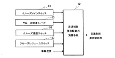
図6は、図4に示す定速制御要求駆動力演算手段12の演算について説明するためのブロック図である。定速制御要求駆動力演算手段12は、車両1を定速度で走行させるような制御を行う際に、エンジン本体4に要求する要求駆動力を演算する手段であって、この定速度走行制御は一般にクルーズ制御と呼ばれている。そして、このクルーズ制御(定速度走行制御)は、運転者がアクセルペダルを踏まずにスイッチの操作のみで車両の速度を一定に保持する制御技術である。図6に示すように、定速制御要求駆動力演算手段12は、クルーズメインスイッチ54、クルーズ加速スイッチ55、クルーズ減速スイッチ56、及びクルーズレジュームスイッチ57のスイッチ信号と、車輪速度と、を入力している。そして、定速制御要求駆動力演算手段12は、前記スイッチを介して運転者から入力されたスイッチ信号と、車輪速度と、に基づいて、速度を保持するために必要な駆動力を演算する(以下、車両速度を保持するためにエンジン本体4に要求する要求駆動力を定速制御要求駆動力と呼ぶ)。
FIG. 6 is a block diagram for explaining the calculation of the constant speed control required driving force calculation means 12 shown in FIG. The constant speed control required driving force calculating means 12 is a means for calculating the required driving force required for the
さらに、運転者の要求に基づいて運転者が加減速スイッチを操作することで、ある車速から規定速度範囲以内となるように加減速できる。従って、運転者が操作せずとも、このような減速動作は、定速度走行制御の一つの運転制御状態である。よって、定速度走行制御における減速駆動制御中である時は、車両が運転者の要求するブレーキ操作以外の減速動作であるので、このような減速は、運転者要求以外の減速(自動減速)である。 Furthermore, when the driver operates the acceleration / deceleration switch based on the driver's request, acceleration / deceleration can be performed so as to be within a specified speed range from a certain vehicle speed. Therefore, even if the driver does not operate, such a deceleration operation is one operation control state of constant speed traveling control. Therefore, when the deceleration drive control in the constant speed traveling control is being performed, the vehicle is performing a deceleration operation other than the brake operation requested by the driver. Therefore, such a deceleration is a deceleration other than the driver request (automatic deceleration). is there.
図7は、図4に示す外部要求駆動力演算手段13の演算について説明するためのブロック図である。図7に記載の外部要求駆動力演算手段13は、前記車両安定化制御装置(ESP)6の内部にある演算手段であり、車両1の外部との関係(外部環境)において、車両が安定走行するために、車両の走行状態に基づいて、エンジン本体4に要求する駆動力を演算している。
FIG. 7 is a block diagram for explaining the calculation of the external required driving force calculation means 13 shown in FIG. The external required driving force calculation means 13 shown in FIG. 7 is a calculation means inside the vehicle stabilization control device (ESP) 6, and the vehicle runs stably in relation to the outside of the vehicle 1 (external environment). Therefore, the driving force required for the
この外部要求駆動力演算手段13は、ステアリング角度センサ61、ヨーレイトセンサ62、横Gセンサ63、車輪速度センサ64などで検出された信号に基づいて、車両の横振れ、内部側の車輪と外側の車輪との速度関係によって、車両の走行(運転)状態を検出している。そして、外部要求駆動力演算手段13は、この検出した車両の走行状態から車両のスリップや横すべりの可能性がある場合は、そのスリップや横すべりを防止すべく、車輪速度や駆動力を制御するに必要な要求駆動力(外部要求駆動力)を演算している。
This external required driving force calculating means 13 is based on signals detected by the
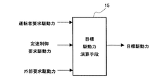
図8は、図4に示す目標駆動力演算手段15の演算について説明するためのブロック図である。目標駆動力演算手段15は、先に示した運転者要求駆動力と、定速制御要求駆動力と、外部要求駆動力と、に基づいて、予め設定した関係に従って目標駆動力の演算している。 FIG. 8 is a block diagram for explaining the calculation of the target driving force calculation means 15 shown in FIG. The target driving force calculation means 15 calculates the target driving force according to a preset relationship based on the driver required driving force, the constant speed control required driving force, and the external required driving force described above. .
例えば、外部駆動要求及び定速度走行制御の駆動要求がない状態では、運転者駆動要求が優先され、目標駆動力は、運転者要求駆動力となる。しかし、定速度走行制御における駆動要求がない状態で、車両を減速させるべく駆動力を低下させる外部駆動要求が発生した場合には、外部要求駆動力と運転者要求駆動力とを比較して、小さい方の駆動力を優先して、目標駆動力として演算する。 For example, in a state where there is no external drive request and constant speed travel control drive request, the driver drive request is given priority, and the target drive force is the driver request drive force. However, when there is an external drive request that reduces the driving force to decelerate the vehicle in the absence of a driving request in constant speed traveling control, the external required driving force is compared with the driver required driving force, The smaller driving force is prioritized and calculated as the target driving force.
また、外部駆動要求がない状態で、運転者が走行中にアクセルペダルを離して定速度走行用のスイッチ操作をした場合には、定速度走行制御するために必要な駆動力を定速制御要求駆動力演算手段12で演算し、演算された定速制御要求駆動力と運転者要求駆動力とを比較して、大きい方の駆動力を優先して、目標駆動力を演算する。 In addition, when there is no external drive request and the driver releases the accelerator pedal and operates the switch for constant speed driving while driving, the driving force required for constant speed driving control is requested. The driving force calculating means 12 calculates and compares the calculated constant speed control required driving force with the driver required driving force, and calculates the target driving force with priority on the larger driving force.
図9は、図4に示す車両走行状態判定手段(DRV)16の判定内容を示す判定フロー図である。ここでは、図5〜8で演算した要求駆動力から、車両がどのような走行状態であるかを分類すべく判定処理を行っている。 FIG. 9 is a determination flowchart showing the determination contents of the vehicle running state determination means (DRV) 16 shown in FIG. Here, a determination process is performed to classify the running state of the vehicle based on the required driving force calculated in FIGS.
図9に示す処理910では目標駆動力と運転者要求駆動力を比較して、比較結果が同じであるかを判定する。そして同じである場合には、車両走行状態を示すパラメータDRVを“0”に設定する。ここに示すDRV=“0”は運転者の要求により駆動制御を行っている状態(運転者駆動制御動作中の状態)を表している。
In a
また、前記処理910の判定結果が不成立である場合は処理912に進む。処理912では、前記目標駆動力と定速制御要求駆動力が同じかどうかを判定し、比較結果が同じである場合は、車両走行状態を示すパラメータDRVを“2”に設定し処理915へ進む。ここに示すDRV=“2”は定速度走行制御による駆動制御を行っている状態(定速度走行制御動作中の状態)を表している。
On the other hand, when the determination result of the
処理915では、定速度走行制御の動作状態が、運転者のクルーズ減速スイッチ操作に応じて車両を強制的に減速している状態かどうかを判定する。処理915での判定で、車両が減速動作状態である場合は、処理919に進み、車両走行状態を示すパラメータDRVを“4”に設定する。ここに示すDRV=“4”は、定速度走行制御における減速動作中の状態を表している。また、前記処理915の判定が不成立の場合には、処理917に進み、処理917では、車両走行状態を示すパラメータDRVを“3”に設定する。ここに示すDRV=“3”は定速度走行制御において減速動作を行っていない状態(定速度走行制御の減速非動作中の状態)を表している。
In
また、前記処理912の判定結果が不成立の場合は、車両走行状態を示すパラメータDRVを“1”に設定し、処理916に進む。ここに示すDRV=“1”は、外部駆動制御中の状態を表している。そして処理916では、前記処理913の外部駆動力動作中状態が外部駆動力低下中であるかどうかを判定し(外部要求駆動力が低下しているかどうかを判定し)、外部駆動力低下中である場合は、処理920へ進み、車両走行状態を示すパラメータDRVを“6”に設定する。ここに示すDRV=“6”は外部駆動力低下制御中状態を表している。
If the determination result of the
一方、処理916で外部駆動力非低下中であると判定した場合には、ステップ918に進み、車両走行状態を示すパラメータDRVを“5”に設定する。ここに示すDRV=“5”は外部駆動力非低下制御中の状態を表す。前記処理916での外部駆動力低下中の状態とは、車両安定化制御装置(外部装置)6が、エンジン本体4の駆動力を強制的に低下させる要求をしている状態を示している。このような要求は、例えば、外部装置であるASRやEPS等からのトルクダウン要求またはその他のパラメータで要求されるもので、最終的に車両の駆動力を低下する目的で外部装置から送信される要求である。
On the other hand, if it is determined in
図10は、図4に示す運転者以外減速要求判定手段(自動減速判定手段)17の判定内容を示す演算フロー図である。まず、処理1000では、車速センサの車速情報、車両走行状態(DRV)、制動制御動作情報を取りこみ、処理1001へ進む。処理1001では、車速情報に応じて車両が減速動作中であるかどうかを判定する。処理1001で、車両が減速していると判定(判定が成立)した場合、処理1002へ進み、車両の減速度(ΔV)を演算する。この車両の減速度ΔVは予め決めた時間間隔で演算されている。そして処理1003へ進み、車両走行が外部駆動力低下制御中の状態(DRV=6)または定速度走行制御の減速度動作中の状態(DRV=4)であるかどうかを判定する。判定結果がDRV=4やDRV=6の場合(判定が成立した場合)は、処理1005へ進み、駆動力低下中相当の減速度(ΔVk)を演算する。処理1005における減速度(ΔVk)演算は予め設定したマップやテーブルにより、各車両走行動作中での駆動力と車速関係で発生する減速度を演算するものである。また、減速度(ΔVk)の演算をテーブル・マップで規定せず、数式等で求めても良い。
FIG. 10 is a calculation flow chart showing the determination contents of the deceleration request determination means (automatic deceleration determination means) 17 other than the driver shown in FIG. First, in
一方、処理1003の判定結果がDRV=4又はDRV=6以外である場合は、処理1004に進み、車両1が、(自動)制動制御動作中であるかどうかを判定する。処理1004においての制動制御動作中であるかの判定は、車両安定化制御装置6の情報に基づいて行われる。例えば、車両の横すべりやスリップを検出したとき、車両安定化制御装置(ESP)6が制動制御装置7に適切な車輪の制動をさせるとともに、車両が制動動作中である情報をエンジン制御装置5に送信する。そして、エンジン制御装置5は、この情報に基づいて、制動制御の判定を行う。そして、処理1004の判定が成立の場合は、処理1005に進み、駆動力低下相当の減速(ΔVk)を演算する。
On the other hand, if the determination result of
次に、処理1002で演算した車両減速(ΔV)と処理1006で演算した駆動力低下相当の減速(ΔVk)を処理1006で比較し、比較結果が所定誤差範囲以内である場合は、処理1008で運転者要求以外の減速動作状態であると判定する。一方、前記処理1004や処理1006で判定が不成立の場合は処理1007に進み、運転者要求の減速動作状態であると判定する。
Next, the vehicle deceleration (ΔV) calculated in the
図11は、図4に示す故障診断禁止判定手段18の演算内容を示す演算フロー図である。処理1100で車速情報、ブレーキ操作情報を取り込み、処理1101で運転者以外の減速動作中の状態であるか、その情報を取りこむ。そして、前記ブレーキ踏み込み状態の情報に応じて、処理1102ではブレーキ操作検出装置(ブレーキスイッチ)50が作動しているかどうかを判定し、ブレーキ操作検出装置50が非作動である場合は、処理1103に進み、車速情報から車両が減速しているかどうかを判定する。
FIG. 11 is a calculation flowchart showing the calculation contents of the failure diagnosis prohibition judging means 18 shown in FIG. In a
処理1103で車両が減速しているという結果を得た場合には、処理1104に進み、車両の減速が運転者のブレーキ操作による減速動作か、運転者の操作以外の減速動作(車両安定化制御装置6が要求する要求駆動力が低下したときにエンジン本体4を減速駆動させる制御する場合の減速動作、定速度走行制御によりエンジン本体4を減速駆動させる制御をする場合の減速動作、制動装置8を自動制動させる制御をする場合の減速動作)か、を判定する。処理1104の判定が成立した場合は、車両の減速が運転者の操作ではなく、運転者の操作以外の減速動作(車両安定化制御装置6が要求する要求駆動力が低下したときにエンジン本体4を減速駆動させる制御をする場合の減速動作、定速度走行制御によりエンジン本体4を減速駆動させる制御をする場合の減速動作、制動装置8を自動制動させる制御をする場合の減速動作)なので、処理1105でブレーキ操作検出装置50の故障診断を禁止する。
If the result of
前記処理1104の判定結果が不成立の場合は、処理1106で運転者要求以外の減速動作が終了してからのディレイ中であるがどうかを判定し、ディレイ中である場合は、まだ運転者要求以外の減速動作が終わっても、車両がまだ減速動作から完全に復帰してない可能性あるので、処理1105でブレーキ操作検出装置50の故障診断を禁止する。前記処理1106での判定が不成立の場合は、運転者による減速動作であるので、前記ブレーキ操作検出装置50が非動作状態を示すことから、ブレーキ操作検出装置50の異常を表すため処理1107でブレーキ操作検出装置50の故障診断を許可する。
If the determination result of the
(第一実施例)
図12は、本実施形態に係る車両の制御装置の第一実施例を示すタイミングチャートであり、要求される駆動力が運転者の制動操作による場合のタイミングチャートである。図12の(1)には、図5〜7で示した外部要求要求駆動力、運転者要求駆動力、及び定速制御要求駆動力が時系列で示されている。図12の(1)に示すように、車両安定化制御装置6などの外部装置からの駆動の要求、及び、定速度走行制御における駆動の要求、が無い場合には、各要求駆動力の絶対値を比較すると次の式1のような関係になっている。
(First Example)
FIG. 12 is a timing chart showing a first example of the vehicle control apparatus according to the present embodiment, and is a timing chart in a case where a required driving force is due to a driver's braking operation. In FIG. 12 (1), the external required driving force, the driver required driving force, and the constant speed control required driving force shown in FIGS. 5 to 7 are shown in time series. As shown in (1) of FIG. 12, when there is no drive request from an external device such as the vehicle
外部要求駆動力>運転者要求駆動力>定速制御要求駆動力…式1
External required driving force> Driver required driving force> Constant speed control required driving force ...
そして、図12の(2)では、図12の(1)に示した各要求駆動力に基づいて得られた目標駆動力を示している。図12の(1)では外部要求駆動力が運転者要求駆動力より大きいので目標駆動力に反映されない。また、定速制御要求駆動力は、運転者要求駆動力より小さいので目標駆動力に反映されず、運転者要求駆動力のみが反映される。
And (2) of
また、図12の(3)に示す波形は、自動制動制御の動作中であるときに出力する波形であり、本実施例では、自動制動制御は行っていない(自動制動制御が非動作中である)ので、出力されていない。また、図12の(4)に示す波形は、運転者が要求している駆動力で制御をしているときに出力する波形であり、図12の(1)に示す如く運転者が駆動力を要求している(運転者駆動力による制御が動作中である)ので、この期間は常時出力されている。さらに、図12の(5)に示す波形は、定速度走行制御により減速動作をしているときに出力する波形であり、図12の(1)に示す如く定速度走行制御を行っていない(定速度走行制御による減速制御が非動作中である)ので、この期間は出力していない。さらにまた、図12の(6)に示す波形は、外部駆動力により駆動力を低下させるような制御を行っているときに出力する波形であり、図12の(1)に示す如く外部駆動力により駆動力を低下させるような制御は行っていない(外部駆動力を低下制御が非動作中である)ので、この期間は出力していない。また、図12の(7)に示す波形は、上の(3)〜(6)の波形に基づいて、運転者要求以外の減速動作中であるときに出力する波形であり、図12の(2)に示す目標駆動力が、運転者要求駆動力に相当しているので、運転者以外の減速動作中ではないので出力されない。よって、このような場合には、ブレーキ操作検出装置50の故障診断は許可される。
The waveform shown in (3) of FIG. 12 is a waveform output when the automatic braking control is in operation. In this embodiment, automatic braking control is not performed (the automatic braking control is not operating). Is not output. Also, the waveform shown in (4) of FIG. 12 is a waveform that is output when control is being performed with the driving force requested by the driver. As shown in (1) of FIG. (Control by the driver driving force is in operation), so this period is always output. Further, the waveform shown in (5) of FIG. 12 is a waveform that is output when the vehicle is decelerating by constant speed running control, and the constant speed running control is not performed as shown in (1) of FIG. 12 ( Since the deceleration control by the constant speed traveling control is not operating), no output is made during this period. Furthermore, the waveform shown in (6) of FIG. 12 is a waveform that is output when control is performed such that the driving force is reduced by the external driving force, and the external driving force is shown in (1) of FIG. Therefore, no control is performed to reduce the driving force (the control for reducing the external driving force is not in operation), and thus no output is made during this period. Further, the waveform shown in (7) of FIG. 12 is a waveform that is output based on the waveforms of (3) to (6) above when a deceleration operation other than the driver's request is being performed. Since the target driving force shown in 2) corresponds to the driver-requested driving force, it is not output because the vehicle is not decelerating other than the driver. Therefore, in such a case, failure diagnosis of the brake
(第二実施例)
図13は、本実施形態に係る車両の制御装置の第二実施例を示すタイミングチャートであり、第一実施例と異なるところは、期間Bにおいて、車両安定化制御装置6などの外部装置からエンジン本体4に駆動要求がされている点である。
(Second embodiment)
FIG. 13 is a timing chart showing a second example of the vehicle control device according to the present embodiment. The difference from the first example is that in period B, the engine is driven from an external device such as the vehicle
図13の(1)に示すように、期間Bでは、外部装置から駆動要求があるので、外部要求駆動力と運転者要求駆動力の大小を比較し、目標駆動力を求める。図13の(2)に示すように、期間Aと期間Cでは、運転者要求駆動力が、外部要求駆動力より小さいので、第一実施例と同様に目標駆動力に運転者要求駆動力が反映される。しかし、図13の(2)の期間Bでは、運転者要求駆動力が、外部要求駆動力より大きいので、目標駆動力に外部要求駆動力が反映される。 As shown in (1) of FIG. 13, in period B, there is a drive request from the external device, so the target drive force is obtained by comparing the magnitudes of the external request drive force and the driver request drive force. As shown in (2) of FIG. 13, in the period A and the period C, the driver required driving force is smaller than the external required driving force. Therefore, as in the first embodiment, the driver required driving force is the target driving force. Reflected. However, in the period B of (2) in FIG. 13, the driver required driving force is larger than the external required driving force, so the external required driving force is reflected in the target driving force.
また、図13の(3)〜(6)に示すように、期間Bでは、外部からの駆動力の要求があるので、図13の(4)に示すように、運転者から要求される駆動力で制御しておらず、図13の(6)に示すように、駆動力の低下を含めた外部から要求される駆動力で制御をしている。そして、このような期間Bでは、図13の(7)に示すように、運転者の操作は反映されず、車両の制御装置10が、車両1を減速させるために、エンジン本体4を減速駆動制御する可能性がある。すなわち、この期間Bでは、運転者の操作以外の減速要求により、自動減速制御を行う可能性があるので、この期間は、ブレーキスイッチの故障診断を禁止している。
Further, as shown in (3) to (6) of FIG. 13, since there is a request for driving force from the outside in period B, as shown in (4) of FIG. 13, driving requested by the driver. It is not controlled by force, and as shown in (6) of FIG. 13, it is controlled by driving force required from the outside including reduction of driving force. In such a period B, as shown in (7) of FIG. 13, the driver's operation is not reflected, and the
(第三実施例)
図14は、本実施形態に係る車両の制御装置の第三実施例を示すタイミングチャートであり、第一実施例と異なるところは、期間Bにおいて、定速度走行制御による駆動要求が反映されて制御されている点である。
(Third embodiment)
FIG. 14 is a timing chart showing a third example of the vehicle control apparatus according to the present embodiment. The difference from the first example is that in period B, the drive request by the constant speed traveling control is reflected and controlled. It is a point that has been.
図14の(1)に示すように、期間Aでは、運転者要求駆動力が、定速制御要求駆動力よりも大きく、期間Bでは、運転者要求駆動力が、定速制御要求駆動力よりも小さいので、図14の(2)に示すように、期間Aでは、第一実施例と同様に目標駆動力に運転者要求駆動力が反映され、期間Bでは、目標駆動力に定速制御要求駆動力が反映される。 As shown in (1) of FIG. 14, in period A, the driver required driving force is greater than the constant speed control required driving force, and in period B, the driver required driving force is greater than the constant speed control required driving force. Therefore, as shown in FIG. 14 (2), in the period A, the driver requested driving force is reflected in the target driving force as in the first embodiment, and in the period B, the constant driving speed control is performed on the target driving force. The required driving force is reflected.
また、図14の(3)〜(6)に示すように、期間Bでは、定速度走行制御による駆動力の要求があるので、図14の(4)に示すように、運転者から要求される駆動力で制御をしていない。特に、図14の(2)に示す期間Cでは、定速度走行制御で要求される駆動力が低下するので、図14の(5)に示すように、定速度走行制御において、車両を減速すべく、エンジン本体4を減速駆動させる制御をしている状態(減速動作中)である。
Further, as shown in (3) to (6) of FIG. 14, in period B, there is a request for driving force by constant speed traveling control, so that it is requested by the driver as shown in (4) of FIG. It is not controlled by the driving force. In particular, during the period C shown in (2) of FIG. 14, the driving force required for the constant speed running control is reduced. Therefore, as shown in (5) of FIG. 14, the vehicle is decelerated in the constant speed running control. Therefore, the
そして、このような期間Cでは、運転者の操作は反映されず、運転者の操作以外の減速要求により減速を行っている(運転者要求以外の自動減速制御中である)ので、この期間は、ブレーキスイッチの故障診断を禁止している。 In such a period C, the driver's operation is not reflected, and the vehicle is decelerating by a deceleration request other than the driver's operation (the automatic deceleration control other than the driver's request is being performed). Brake switch failure diagnosis is prohibited.
図15及び図16は、ブレーキ操作検出装置50の異常検出の許可又は禁止を説明するためのタイミングチャートである。図15は、ブレーキ操作検出装置50の故障診断を許可する場合のタイミングチャートである。図15の(1)は、走行している車両の速度を示しており、運転者のブレーキ操作により車両を減速させた速度状態を示している。また、図15の(2)は、車両運転動作開始からのブレーキ操作検出装置50の作動する状態を示しており、図15の(3)は図12〜図14の(7)に示す波形と同様に、運転者要求以外により車両が減速動作をしたか否かを示している。さらに、図15の(4)に示す波形は、ブレーキ操作検出装置50の異常検出を禁止するか否かを示している。
15 and 16 are timing charts for explaining permission or prohibition of abnormality detection of the brake
図15の(1)〜(3)に示すように、期間Δtにおいて、運転者がブレーキ操作を行って、車両が減速しているにも関わらずブレーキ操作検出装置50は非動作状態であるので、ブレーキ操作検出装置50が故障状態(異常)である。このような異常を検出するために、図15の(4)に示す如くブレーキ操作検出装置50の故障診断を許可し、ブレーキ操作検出装置診断禁止フラグを設定しないようにする。
As shown in (1) to (3) of FIG. 15, in the period Δt, the brake
図16は運転者以外の減速動作時においてブレーキ操作検出装置50の故障診断を禁止する動作を説明するためのタイミングチャートである。図16の(1)〜(2)は図15に示す波形と同じ波形を示している。図16の(3)に示すように、期間Δtでは、図16の(1)の運転者以外の減速を行ったので、運転者要求以外の減速動作中の信号が出力される。この期間Δtでは、ブレーキ操作検出装置50が非動作状態で、運転者以外の減速動作により車両が減速動作状態になっているので、ブレーキ操作検出装置50が異常であることの誤検出を防止するために、ブレーキ操作検出装置50の診断禁止フラグを設定し、ブレーキ操作検出装置50の故障診断を禁止する。
FIG. 16 is a timing chart for explaining an operation for prohibiting the failure diagnosis of the brake
また、運転者以外減速動作期間中であると判断された場合は、ブレーキ操作検出装置50の故障診断(異常検出)を禁止するにあたっては、外部駆動力低下中や定速度走行制御の減速動作や自動制動制御動作等の運転者要求以外減速動作が終了しても、実際に車両が運転者以外の減速動作から完全に復帰するまでにいくらかの時間かかることを想定している。従って、図16の(4)に示すように、運転者要求以外の減速動作後の時間遅れを考慮して、さらに所定時間の間、ブレーキ操作検出装置50の故障診断の禁止時間を延長(ディレイ)する。これによって、運転者要求以外の駆動力低下要求により駆動力を低下させるような要求が終了した場合でも、自動減速制御が終了後の所定時間の間、故障診断を禁止しているので、ブレーキ操作検出装置50を異常であると誤診断することはない。
In addition, when it is determined that a deceleration operation period other than the driver is in progress, in order to prohibit the failure diagnosis (abnormality detection) of the brake
図17は、車両速度と駆動トルクの関係を示した図である。近年、車両の駆動トルクを検出する技術が拡大されており、車両の駆動トルクが分かれば、逆算して、そのギア比で起きている車両速度を演算することが可能となる。従って、本実施形態において、車両の速度変化をトルク変化として演算することができる。 FIG. 17 is a diagram showing the relationship between the vehicle speed and the driving torque. In recent years, techniques for detecting the driving torque of a vehicle have been expanded. If the driving torque of the vehicle is known, it is possible to calculate the vehicle speed occurring at the gear ratio by performing a reverse calculation. Therefore, in this embodiment, a change in the speed of the vehicle can be calculated as a change in torque.
図17は、駆動トルクと車速の関係の一例であり、駆動トルクと車速の関係をギア比やその他のパラメータでテーブルやマップから演算しても良い。このことにより運転者要求以外の減速や車両の減速そのものを駆動トルクの変化や駆動トルクと運転者要求駆動トルクの比較により判断できる。そして、車両の減速が運転者要求減速、外部駆動要求や定速度制御の減速動作要求や自動制動制御要求で起きている運転者以外減速要求かを正確に区別することが可能となる。そして、制御装置が、このような車両を自動減速させるような制御を行っているか識別することで、より正確にブレーキ操作検出装置の異常検出できる。 FIG. 17 shows an example of the relationship between the driving torque and the vehicle speed, and the relationship between the driving torque and the vehicle speed may be calculated from a table or map using a gear ratio or other parameters. As a result, deceleration other than the driver request or vehicle deceleration itself can be determined by a change in the drive torque or a comparison between the drive torque and the driver request drive torque. In addition, it is possible to accurately distinguish whether the vehicle deceleration is a driver request deceleration, an external drive request, a deceleration operation request for constant speed control, or a deceleration request other than the driver that is caused by an automatic braking control request. And it is possible to detect the abnormality of the brake operation detecting device more accurately by identifying whether or not the control device is performing such control that automatically decelerates the vehicle.
以上、本発明の一実施形態について詳述したが、本発明は、前記の実施形態に限定されるものではなく、特許請求の範囲に記載された本発明の精神を逸脱しない範囲で、種々の設計変更を行うことができるものである。 Although one embodiment of the present invention has been described in detail above, the present invention is not limited to the above-described embodiment, and various modifications can be made without departing from the spirit of the present invention described in the claims. Design changes can be made.
本発明では外部装置として車両安定化制御装置を用いたが、アンチロックブレーキ制御装置、車間距離制御装置、自動変速制御装置、トラクションコントロール制御装置などを用いても良く、またはこれらの装置の組み合わせであってもよい。さらに、本発明では、車両はエンジンにより駆動するが、バッテリにより駆動する電気自動車でもよく、また、これらの組み合わせによって駆動するハイブリッド車両であってもよい。 In the present invention, the vehicle stabilization control device is used as the external device. However, an anti-lock brake control device, an inter-vehicle distance control device, an automatic transmission control device, a traction control control device, or the like may be used, or a combination of these devices. There may be. Furthermore, in the present invention, the vehicle is driven by the engine, but may be an electric vehicle driven by a battery, or may be a hybrid vehicle driven by a combination thereof.
さらに、本実施形態に示す要求駆動力は、エンジンに要求する駆動力であっても良く、駆動力に比例した値であるならば、特に限定されるものではない。 Furthermore, the required driving force shown in the present embodiment may be a driving force required for the engine, and is not particularly limited as long as it is a value proportional to the driving force.
本発明に係る車両の制御装置は、運転者のブレーキ操作による減速と同様の自動減速を行うに制御装置に適している。具体的には、ABS制御装置、車間距離制御装置、定速度走行制御制御装置、自動変速機制御装置、トラクションコントロール制御装置、または車両安定化制御装置などを備えた車両に適しており、特に、ブレーキ操作の信号に基づいて自動制御を行う車両には、特に有効である。 The vehicle control apparatus according to the present invention is suitable for a control apparatus for performing automatic deceleration similar to deceleration by a driver's brake operation. Specifically, it is suitable for vehicles equipped with an ABS control device, an inter-vehicle distance control device, a constant speed travel control control device, an automatic transmission control device, a traction control control device, a vehicle stabilization control device, etc. This is particularly effective for a vehicle that performs automatic control based on a brake operation signal.
1…車両,4…エンジン本体(駆動装置),5…エンジン制御装置,6…車両安定化制御装置,7…制動制御装置,8…制動装置,10…車両の制御装置,11…運転者要求駆動力演算手段,12…定速制御要求駆動力演算手段,13…外部要求駆動力演算手段,17…自動減速判定手段(運転者以外減速要求判定手段),18…故障診断禁止判定手段,20…故障診断手段,50…ブレーキ操作検出装置
DESCRIPTION OF
Claims (7)
該故障診断手段は、前記車両が自動減速制御をしていると判定したときには、前記故障診断を禁止することを特徴とする車両の制御装置。 A brake detection means for detecting a deceleration of the vehicle; and a braking operation detection means for detecting a braking operation of the braking device of the vehicle. The braking operation detection means based on the detection result of the deceleration and the braking operation. A vehicle control device provided with a failure diagnosis means for diagnosing a failure of the vehicle,
The failure diagnosis means prohibits the failure diagnosis when it is determined that the vehicle is performing automatic deceleration control.
The vehicle according to any one of claims 2 to 6, wherein the determination that the control for the deceleration driving is performed is made based on a driving force requested by the control device to the driving device. Control device.
Priority Applications (1)
| Application Number | Priority Date | Filing Date | Title |
|---|---|---|---|
| JP2004312370A JP2006123631A (en) | 2004-10-27 | 2004-10-27 | Control device of vehicle |
Applications Claiming Priority (1)
| Application Number | Priority Date | Filing Date | Title |
|---|---|---|---|
| JP2004312370A JP2006123631A (en) | 2004-10-27 | 2004-10-27 | Control device of vehicle |
Publications (1)
| Publication Number | Publication Date |
|---|---|
| JP2006123631A true JP2006123631A (en) | 2006-05-18 |
Family
ID=36718785
Family Applications (1)
| Application Number | Title | Priority Date | Filing Date |
|---|---|---|---|
| JP2004312370A Pending JP2006123631A (en) | 2004-10-27 | 2004-10-27 | Control device of vehicle |
Country Status (1)
| Country | Link |
|---|---|
| JP (1) | JP2006123631A (en) |
Cited By (5)
| Publication number | Priority date | Publication date | Assignee | Title |
|---|---|---|---|---|
| JP2012091647A (en) * | 2010-10-26 | 2012-05-17 | Nissan Motor Co Ltd | Diagnostic device of brake |
| JP2013180632A (en) * | 2012-02-29 | 2013-09-12 | Daihatsu Motor Co Ltd | Abnormality detector for brake negative pressure sensor |
| JP2014237421A (en) * | 2013-06-10 | 2014-12-18 | 三菱自動車工業株式会社 | Braking device |
| JP2017061323A (en) * | 2017-01-13 | 2017-03-30 | 三菱自動車工業株式会社 | Braking device |
| CN112897267A (en) * | 2021-01-15 | 2021-06-04 | 日立楼宇技术(广州)有限公司 | Elevator brake detection method, device, equipment and medium |
-
2004
- 2004-10-27 JP JP2004312370A patent/JP2006123631A/en active Pending
Cited By (6)
| Publication number | Priority date | Publication date | Assignee | Title |
|---|---|---|---|---|
| JP2012091647A (en) * | 2010-10-26 | 2012-05-17 | Nissan Motor Co Ltd | Diagnostic device of brake |
| JP2013180632A (en) * | 2012-02-29 | 2013-09-12 | Daihatsu Motor Co Ltd | Abnormality detector for brake negative pressure sensor |
| JP2014237421A (en) * | 2013-06-10 | 2014-12-18 | 三菱自動車工業株式会社 | Braking device |
| JP2017061323A (en) * | 2017-01-13 | 2017-03-30 | 三菱自動車工業株式会社 | Braking device |
| CN112897267A (en) * | 2021-01-15 | 2021-06-04 | 日立楼宇技术(广州)有限公司 | Elevator brake detection method, device, equipment and medium |
| CN112897267B (en) * | 2021-01-15 | 2022-04-29 | 日立楼宇技术(广州)有限公司 | Elevator brake detection method, device, equipment and medium |
Similar Documents
| Publication | Publication Date | Title |
|---|---|---|
| JP5336052B2 (en) | Cruise control device, program, and target vehicle speed setting method | |
| US7002452B2 (en) | Collision preventing apparatus for a vehicle | |
| CN106553645B (en) | automatic parking control system and control method based on the system | |
| KR20170117322A (en) | Vehicle running control apparatus | |
| EP3459820B1 (en) | Driving support device | |
| US9108623B2 (en) | System and method of controlling motor vehicle operation | |
| JP5299552B2 (en) | Vehicle power hop detection method | |
| JP2006348854A (en) | Traction control device | |
| JP5867353B2 (en) | Vehicle control device | |
| CN108350816A (en) | Idling flameout control method and idling flameout control device | |
| JP5843833B2 (en) | Vehicle control device | |
| JP4163844B2 (en) | Vehicle rear-end collision avoidance device | |
| JP2006123631A (en) | Control device of vehicle | |
| JPWO2006057070A1 (en) | Automotive control device | |
| JP2008030677A (en) | Vehicular deceleration control apparatus | |
| US20190161065A1 (en) | Method of changing abs control mode by using analysis of driving pattern | |
| JP5169539B2 (en) | Downhill road speed control device | |
| JP4561333B2 (en) | Driver's control dependence detecting device and vehicle deceleration control device having the same | |
| JP2011527260A (en) | Apparatus and corresponding method for assessing lateral acceleration of an automobile | |
| JP2021109558A (en) | Vehicle travel control device | |
| JP2010023579A (en) | Travel control device | |
| JP2010249080A (en) | Road surface slope determination method and control device for on-vehicle internal combustion engine | |
| JP2009275591A (en) | Vehicle controller | |
| JP4148028B2 (en) | Vehicle travel control device | |
| JP2010149568A (en) | Vehicle driving support device and vehicle driving support method |