JP2006111444A - Chute for sorting/inspection apparatus - Google Patents
Chute for sorting/inspection apparatus Download PDFInfo
- Publication number
- JP2006111444A JP2006111444A JP2005218036A JP2005218036A JP2006111444A JP 2006111444 A JP2006111444 A JP 2006111444A JP 2005218036 A JP2005218036 A JP 2005218036A JP 2005218036 A JP2005218036 A JP 2005218036A JP 2006111444 A JP2006111444 A JP 2006111444A
- Authority
- JP
- Japan
- Prior art keywords
- chute
- product
- station
- sorting
- inspection
- Prior art date
- Legal status (The legal status is an assumption and is not a legal conclusion. Google has not performed a legal analysis and makes no representation as to the accuracy of the status listed.)
- Pending
Links
Images


Classifications
-
- B—PERFORMING OPERATIONS; TRANSPORTING
- B07—SEPARATING SOLIDS FROM SOLIDS; SORTING
- B07C—POSTAL SORTING; SORTING INDIVIDUAL ARTICLES, OR BULK MATERIAL FIT TO BE SORTED PIECE-MEAL, e.g. BY PICKING
- B07C5/00—Sorting according to a characteristic or feature of the articles or material being sorted, e.g. by control effected by devices which detect or measure such characteristic or feature; Sorting by manually actuated devices, e.g. switches
- B07C5/02—Measures preceding sorting, e.g. arranging articles in a stream orientating
-
- B—PERFORMING OPERATIONS; TRANSPORTING
- B07—SEPARATING SOLIDS FROM SOLIDS; SORTING
- B07C—POSTAL SORTING; SORTING INDIVIDUAL ARTICLES, OR BULK MATERIAL FIT TO BE SORTED PIECE-MEAL, e.g. BY PICKING
- B07C5/00—Sorting according to a characteristic or feature of the articles or material being sorted, e.g. by control effected by devices which detect or measure such characteristic or feature; Sorting by manually actuated devices, e.g. switches
- B07C5/34—Sorting according to other particular properties
- B07C5/342—Sorting according to other particular properties according to optical properties, e.g. colour
-
- B—PERFORMING OPERATIONS; TRANSPORTING
- B07—SEPARATING SOLIDS FROM SOLIDS; SORTING
- B07C—POSTAL SORTING; SORTING INDIVIDUAL ARTICLES, OR BULK MATERIAL FIT TO BE SORTED PIECE-MEAL, e.g. BY PICKING
- B07C2501/00—Sorting according to a characteristic or feature of the articles or material to be sorted
- B07C2501/0081—Sorting of food items
Abstract
Description
本発明は、選別・検査装置に使用するシュートに関し、特に生産品を選別ステーション又は検査ステーションに届けるシュートに生産品が供給されるようになっている装置に関する。この種の選別装置は、米国特許第4,513,868号、第4,630,736号及び第5,628,411号に記載されている。検査装置も同じ技術を使用できるが、しかしそれは、生産品の流れから不合格品を排除するよりもむしろデータを集めることを目的としている。 The present invention relates to a chute for use in a sorting / inspection apparatus, and more particularly to an apparatus in which a product is supplied to a chute that delivers the product to a sorting station or an inspection station. Such sorters are described in U.S. Pat. Nos. 4,513,868, 4,630,736 and 5,628,411. Inspection equipment can use the same technology, but it is aimed at collecting data rather than eliminating rejects from the product stream.
生産品によっては、それら生産品がシュートの下方端を離れるときに個々の生産品の向き及び位置が定められるように、溝付きのシュート又はチャンネル付きのシュートが使用される。これによって、選別プロセス又は検査プロセスが促進されることになり、選別装置では、生産品の流れから個々の生産品を排除するのに使われる装置及び機構が、的確に選定された個々の生産品だけを確実に取り扱えるようになる。 Depending on the product, grooved chutes or channeled chutes are used so that the orientation and position of individual products is determined when they leave the lower end of the chute. This facilitates the sorting or inspection process. In the sorting device, the equipment and mechanisms used to exclude individual products from the product stream are the individual products that have been properly selected. Can be handled reliably.
本発明に係る種類の装置における検査ステーションでは、異なった品質の個々の生産品を区別するために一般的に光学システムが使用されており、個別に容易に識別されるように生産品の流れの中にある個々の生産品それぞれが隣にある個々の生産品すべてから離れているのが理想的である。同時に、できるだけ多くの生産品が生産品の流れに存在することが望ましいことは当然である。生産品は、加振機から流れ出て行くので比較的ゆっくり移動している。生産品が途切れること無く加振トレイを離れてチャンネル付きシュート上に供給されていく公知の装置では、生産品はチャンネル内に途切れること無く供給される。もし、二つ以上の穀粒がチャンネル内に同時に入れば、それらは個々の穀粒が流れる場合よりも若干遅くそのチャンネル内を並んで移動することになり、個々の穀粒がそれらに追い着き、次いで塊を形成することになる。チャンネル内でこれら生産品の塊が同じ速度で移動してシュート上で離れなくなる傾向が一旦生じると、その場合一つ一つの生産品の流れと言うよりもむしろ塊として検査ステーションを通って行くことになる。このようになると検査効率が低下することになり、また選別装置では欠陥が検出された場合に二つ以上の穀粒が排除されることになる。このような事態を回避するために、シュート内への生産品の流速を制限する必要があり、装置の処理能力が低減する。 In an inspection station of the type of apparatus according to the invention, an optical system is generally used to distinguish individual products of different qualities, so that the flow of the product can be easily identified individually. Ideally, each individual product within is separated from all adjacent products. At the same time, it is naturally desirable that as many products as possible be present in the product stream. Since the product flows out of the shaker, it moves relatively slowly. In the known apparatus in which the product is supplied to the chute with a channel by leaving the vibration tray without interruption, the product is supplied without interruption in the channel. If two or more kernels enter the channel at the same time, they will move side-by-side in that channel slightly later than if the individual kernels flow, and the individual kernels will catch up with them. Then, a lump will be formed. Once there is a tendency for these product masses to move at the same speed in the channel and not leave on the chute, then go through the inspection station as a mass rather than a single product flow. become. In such a case, the inspection efficiency is lowered, and when a defect is detected in the sorting apparatus, two or more grains are excluded. In order to avoid such a situation, it is necessary to limit the flow rate of the product into the chute, which reduces the processing capacity of the apparatus.
本発明は、多数の生産品の流れを検査ステーションに届ける装置において、チャンネル付きシュート又は溝付きシュートを使用するメリットを活かそうとするものであるが、塊になるリスクを低減し、それによって大量で流速が速くても検査効率が維持されるようにするものである。本発明によれば、このように選別装置又は検査装置において使用されるシュートは、上端部及び下端部を有し、シュートの上端部に滑らかな表面を備えた第一部分と、シュートの下端部に向かって延びた溝又はチャンネルが形成された第二部分とを有している。我々は、生産品の流れにおける個々の生産品が第2部分に到達する時までにより一様に隔離されるように、第1部分の滑らかな表面が個々の生産品を互いに分離させるように作用することを見出した。このようにして、塊になるリスクが低減される。 The present invention seeks to take advantage of the advantage of using a channeled chute or grooved chute in an apparatus that delivers a large number of product streams to an inspection station, but reduces the risk of clumping, thereby increasing the volume. The inspection efficiency is maintained even when the flow rate is high. According to the present invention, the chute used in the sorting device or the inspection device in this way has an upper end portion and a lower end portion, a first portion having a smooth surface at the upper end portion of the chute, and a lower end portion of the chute. And a second portion formed with a groove or channel extending toward the top. We act so that the smooth surface of the first part separates the individual products from each other so that the individual products in the product stream are more evenly separated by the time they reach the second part. I found out. In this way, the risk of clumping is reduced.
本発明に係るシュートにおいては、シュート上の生産品が第一部分から第二部分上又は第二部分内へと直接流れるように、第一部分及び第二部分が通常直に接している。この第一部分の滑らかな表面は、その下縁を第二部分におけるチャンネル又は溝の壁面に直接重ねて連続させることができる。このような構成によって、生産品の流れにおける個々の生産品は、第一部分から第二部分に滑らかに移動できるものであり、その間実質的に一方又は他方の構成要素と常時接触したままになっている。 In the chute according to the present invention, the first part and the second part are usually in direct contact so that the product on the chute flows directly from the first part onto the second part or into the second part. The smooth surface of this first part can be continued with its lower edge directly overlying the wall of the channel or groove in the second part. With such a configuration, individual products in the product flow can move smoothly from the first part to the second part, while remaining substantially in constant contact with one or the other component during that time. Yes.
その最も簡単な形態では、本発明に係るシュートにおける第一部分は、第二部分におけるチャンネル又は溝が第一部分の下のシュート上端部に向かって延びるように、第二部分の一部分を覆って配置されたプレートを有している。好都合なことには、第一部分は平坦なプレートから構成することができ、そして、第二部分は、別のプレートに平行な平面に平行チャンネル又は平行溝の配列を有することができる。しかし、第一部分と第二部分のいずれか一方又は両方は、湾曲又は起伏した輪郭を有することもでき、多様な輪郭の組み合わせにより、本発明を各種適用するうえで幾つかの長所をもたらす。第一部分は、一般にシュートの上端部から下端部までのシュート長さの少なくとも20%まで延びているが、通常は、シュート長さの50%を超えて延びることはない。 In its simplest form, the first part of the chute according to the invention is arranged over a part of the second part so that the channel or groove in the second part extends towards the upper chute below the first part. Has a plate. Conveniently, the first part may consist of a flat plate and the second part may have an array of parallel channels or grooves in a plane parallel to another plate. However, either one or both of the first part and the second part can have curved or undulating contours, and various contour combinations provide several advantages for various applications of the present invention. The first portion generally extends at least 20% of the chute length from the upper end to the lower end of the chute, but usually does not extend beyond 50% of the chute length.
本発明に係るシュートを使用した選別装置は、上述のように、通常は選別ステーションに光学システムを有している。適切な光学式選別システムは、前記参照した特許に記載されている。シュートの上端部において、供給ステーションは、通常ホッパー又は他のタンクからシュートに供給される生産品を搬送する水平コンベヤを有している。一般にコンベヤは、振動コンベヤであり、個々の生産品がシュートに供給される前に、それらをある程度分離するものである。 As described above, the sorting apparatus using the chute according to the present invention usually has an optical system in the sorting station. Suitable optical sorting systems are described in the above referenced patents. At the upper end of the chute, the supply station usually has a horizontal conveyor that transports the product supplied to the chute from a hopper or other tank. In general, the conveyor is an oscillating conveyor that separates the individual products before they are fed to the chute.
上述のように、本発明は、検査装置においても同様に有用なものであり、その検査装置では、シュートを離れた流れの中にある生産品が、選別よりもむしろデータ収集の目的で検査される。丁度参照した種類の選別装置で使用されているものと同様の検査機構を採用することができる。そのような検査は、破損したり又は歪んだりした個々の生産品のような、機械を流れて通過していく生産品についての属性を収集するのに役立つものである。 As mentioned above, the present invention is equally useful in inspection equipment, in which products in the flow off the chute are inspected for the purpose of data collection rather than sorting. The An inspection mechanism similar to that used in the sorter of the type just referenced can be employed. Such inspection is useful for collecting attributes about products that flow through the machine, such as individual products that are damaged or distorted.
溝付きシュート又はチャンネル付きシュートは、比較的多数の欠陥生産品を含んだ生産品に特に適している。本発明の一つ応用として、二段階となっている『再選別』プロセスがある。第一段階では、極めて大量の良品が品質の劣った生産品と共に排斥されるようにすることで、非常に高品質の生産品のみが受け入れられる。この第一合格品からの排斥品は、欠陥生産品の含有割合がより高くなっており、良好な生産品の大部分を回収するために次に再度選別される。チャンネル付きシュートは、通常この第二合格品のために使用される。一般に、全生産品の流れの10%未満が第二選別を受ける。 Grooved chutes or channeled chutes are particularly suitable for products containing a relatively large number of defective products. One application of the present invention is a “resort” process that has two stages. In the first stage, only a very high quality product is accepted by ensuring that a very large number of good products are rejected together with a poor quality product. The rejected product from the first acceptable product has a higher content of defective products and is then re-sorted to recover most of the good products. A chute with a channel is usually used for this second acceptable product. Generally, less than 10% of the total product stream undergoes a second sort.
本発明のシュートは、例えばコーヒ豆や米などを含む広範囲の生産品を選別して検査する装置に有用である。ほぼ細長い形状を有した生産品は、当然、自然にチャンネル又は溝において自ら整列する傾向にあるが、チャンネル及び溝は、大きく異なった形状を有した生産品の動きを制御するのにも有効である。 The chute of the present invention is useful for an apparatus for selecting and inspecting a wide range of products including, for example, coffee beans and rice. A product with a generally elongated shape naturally tends to align itself in the channel or groove, but the channel and groove are also effective in controlling the movement of products with very different shapes. is there.
以下、添付した概略図面を参照し、例示によって本発明を説明する。
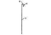
図1に示すように、本発明の第一実施例に係るシュートは、ほぼ長方形状を成し、アルミニウム合金又は他の適当な材料から成る長い本体2を基本としており、多数の溝4がその本体の全長にわたって延びている。図2及び図3から分かるように、シュートの第一部分6は、本体2の端部に取外し可能に搭載された別体の構成部品から構成されている。第一部分6は、ステンレススチィール又は別な適当な材料で成形されており、本体2の端部に重なって適合するクリップ8を形成するように上縁部10が曲げられている。第一部分6の露出面と、本体2の溝付き面4は、その上を個々の生産品が確実に滑らかに通過していくように高度に磨かれている。
The invention will now be described by way of example with reference to the accompanying schematic drawings, in which:
As shown in FIG. 1, the chute according to the first embodiment of the present invention has a substantially rectangular shape and is based on a long
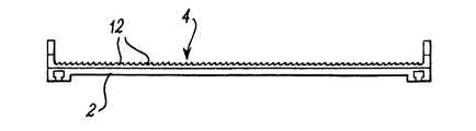
図4は、図1におけるシュートの第二部分を形成している本体2の溝を示している。各溝は、標準的なU−形状又はV−形状の横断面とすることができ、またシュートを使用することとなる生産品に応じて、2mm2から25mm2の範囲の横断面積を有することができる。各溝の一般的な深さは3mm以下である。
FIG. 4 shows the groove of the
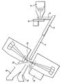
図5は、図1に示されている種類のシュートが、前記参照した米国特許第4,513,868号、第4,630,736号及び第5,628,411号で開示されている種類の広い範囲の選別装置にどのようにして使用されるかを示している。本装置は、選別又は検査される生産品を補給加振機18上に搭載されたトレイ16に供給する受け入れホッパー14を有している。加振機を作動させることで、生産品を前記説明したように高度に磨かれた滑らかな表面を有するコンベヤの第一部分6の上端部に供給する。シュートの第一部分6上に放出された生産品は、その表面上で自由に横方向及び下方向に移動し、上記第二部分2に供給されて行く。その第二部分上で個々の生産品は、下方向に進行するに従って溝12(図4)内へと落下して行き、それら溝内又はそれら溝上で整列される。このようなより規則正しい配列状態で、個々の生産品はシュートの排出端部20から検査ゾーン22へと放出される。その検査ゾーン22では、個々の生産品が前記参照した特許に開示された種類の光学技術を使用して照らされ、監視される。本装置が検査のみに使用される場合、その際個々の生産品は妨害を受けることなく容器24内に連続移動する。本装置が選別のために使用される場合、その際エゼクターが、通常は空圧式エゼクターが、検査装置によって発生される信号に応答して生産品の流れから個々の品を排除するために組み込まれる。排除された個々の生産品は、生産品の流れから排斥容器28内へと逸らされる。
FIG. 5 shows the type of chute of the type shown in FIG. 1 disclosed in the above referenced US Pat. Nos. 4,513,868, 4,630,736 and 5,628,411. Shows how it can be used in a wide range of sorting devices. The apparatus includes a
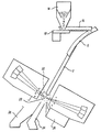
図6は、図5のものに基本的に類似した装置を示しているが、そのシュートの第一部分6は湾曲した輪郭を有している。この輪郭によって、トレイ16から供給された個々の生産品は、溝付きの第二部分2に向かって多少より緩やかに加速して行く。これは、トレイからの供給速度が比較的遅い場合や、第二部分への生産品の供給速度を遅くしたいと言う必要性又は要望がある場合に役立つものである。これにより個々の生産品の横方向への分離を改善することができる。
FIG. 6 shows a device essentially similar to that of FIG. 5, but the
本発明に係る代表的なシュートは、約300mm幅と約1200mm長さとを有する。第一部分の長さは、通常シュート全長の少なくとも20%、好ましくは50%以下になっている。図1の実施例では、約300mm(25%)の長さになっており、図5及び図6では約40%になっている。厚さは、第一部分からチャンネル又は溝への段移行を最小にするためにできるだけ薄くするべきであり、また第一部分の下方縁部は、いかなる供給遅れをも回避するために、当然ぎざぎざが全く無い状態にすべきである。 A typical chute according to the present invention has a width of about 300 mm and a length of about 1200 mm. The length of the first portion is usually at least 20% of the total length of the chute, preferably 50% or less. In the embodiment of FIG. 1, the length is about 300 mm (25%), and in FIGS. 5 and 6, it is about 40%. The thickness should be as thin as possible to minimize step transitions from the first part to the channel or groove, and the lower edge of the first part is of course not jagged to avoid any supply delay. There should be no state.
説明してきたシュートは、各々異なった材料から造られた二つの部分により構成されている。しかし、一方の部分から他方の部分への滑らかな移行が確保されるならば、両部分は単一の材料片から同等に成形又は機械加工され得るものである。第二部分も、別々の構成部品から造られたり、又はシュートが一部分となっている装置上に組み付けられたり若しくは単にグループ化されて搭載される個別のチャンネルから造られたりもする。具体的に説明してきたものとは異なった第一部分の形状を使用し、生産品がシュートのチャンネル付き又は溝付きの第二部分に到達する前に、生産品を横方向及び移行方向に種々の程度に分離させることもできる。 The chute that has been described consists of two parts, each made from a different material. However, if a smooth transition from one part to the other is ensured, both parts can be equally molded or machined from a single piece of material. The second part can also be made from separate components, or can be assembled on a device where the chute is a part, or it can be made from individual channels that are simply grouped and mounted. Use a different first part shape than what has been specifically described, before the product reaches the chute channeled or grooved second part, it can be It can also be separated to the extent.
我々がテストしたところ、選別性能において特に改良がみられることが分かった。すなわち、前記参照した種類の代表的な300mmシュートにおいては、比較的高い流速、例えば1000kg/hour程度以上の流速で、シュートのチャンネル付き第二部分において塊になるのがより少なくなった。滑らかな第一部分が、個々の生産品をチャンネル付き第二部分に入る前に横方向及び流れ方向の両方向に自由に分離させるので、前記テストは長粒米を選別するのに特に有利であった。 We tested and found that there was a particular improvement in sorting performance. That is, the representative 300 mm chute of the above-mentioned type is less likely to clump in the second part with the channel of the chute at a relatively high flow rate, for example, a flow rate of about 1000 kg / hour or more. The test was particularly advantageous for sorting long grain rice because the smooth first part allows individual products to freely separate in both the transverse and flow directions before entering the channeled second part. .
Claims (20)
20. A method as claimed in any one of claims 17 to 19 wherein the granular product comprises an edible item.
Applications Claiming Priority (1)
| Application Number | Priority Date | Filing Date | Title |
|---|---|---|---|
| GB0416717A GB2416533B (en) | 2004-07-27 | 2004-07-27 | Chutes for sorting and inspection apparatus |
Publications (2)
| Publication Number | Publication Date |
|---|---|
| JP2006111444A true JP2006111444A (en) | 2006-04-27 |
| JP2006111444A5 JP2006111444A5 (en) | 2012-10-11 |
Family
ID=32947501
Family Applications (1)
| Application Number | Title | Priority Date | Filing Date |
|---|---|---|---|
| JP2005218036A Pending JP2006111444A (en) | 2004-07-27 | 2005-07-27 | Chute for sorting/inspection apparatus |
Country Status (10)
| Country | Link |
|---|---|
| US (1) | US8100268B2 (en) |
| EP (1) | EP1799363B1 (en) |
| JP (1) | JP2006111444A (en) |
| KR (2) | KR20120096114A (en) |
| CN (1) | CN1733370B (en) |
| AT (1) | ATE552920T1 (en) |
| BR (1) | BRPI0513800B1 (en) |
| ES (1) | ES2385487T3 (en) |
| GB (1) | GB2416533B (en) |
| WO (1) | WO2006010873A1 (en) |
Cited By (3)
| Publication number | Priority date | Publication date | Assignee | Title |
|---|---|---|---|---|
| JP2011041872A (en) * | 2009-08-19 | 2011-03-03 | Toyo Glass Co Ltd | Matter discrimination device, and matter sorting device |
| JP2012505808A (en) * | 2008-10-20 | 2012-03-08 | ビューラー ソーテックス リミテッド | Chute for sorting and inspection equipment |
| JP2019526327A (en) * | 2016-08-20 | 2019-09-19 | ビューラー・アクチエンゲゼルシャフトBuehler AG | Apparatus and method for sterilizing and / or sterilizing granular articles and cartridge |
Families Citing this family (9)
| Publication number | Priority date | Publication date | Assignee | Title |
|---|---|---|---|---|
| GB2416533B (en) | 2004-07-27 | 2008-06-18 | Sortex Ltd | Chutes for sorting and inspection apparatus |
| KR100830613B1 (en) * | 2007-10-01 | 2008-05-22 | 주식회사에이멕스 | Support panel of chute for color discerning apparatus |
| GB2464689A (en) * | 2008-10-21 | 2010-04-28 | Buhler Sortex Ltd | Chute for inspection and sorting apparatus |
| US9221186B2 (en) * | 2009-04-09 | 2015-12-29 | David W. Scaroni | Produce processing apparatus |
| US20130008837A1 (en) * | 2011-07-06 | 2013-01-10 | Key Technology, Inc. | Sorting apparatus |
| JP5807448B2 (en) * | 2011-08-26 | 2015-11-10 | 株式会社サタケ | Chute for optical sorter and optical sorter |
| US9124109B2 (en) | 2012-03-30 | 2015-09-01 | Toyota Motor Engineering & Manufacturing North America, Inc. | Console assembly with charging state indicator |
| CN105366331A (en) * | 2015-12-03 | 2016-03-02 | 贵州遵义新佳裕食品有限公司 | Pepper tidying device |
| CN109665380A (en) * | 2018-11-12 | 2019-04-23 | 际华三五零六纺织服装有限公司 | A kind of yarn bobbin bobbin oscillating machine |
Citations (7)
| Publication number | Priority date | Publication date | Assignee | Title |
|---|---|---|---|---|
| JPS49134060A (en) * | 1972-10-27 | 1974-12-24 | ||
| JPS6026877Y2 (en) * | 1979-10-17 | 1985-08-13 | 株式会社 サタケ | Feeding device in color sorter |
| JPS61171710U (en) * | 1985-04-11 | 1986-10-24 | ||
| JPH0389981A (en) * | 1989-08-31 | 1991-04-15 | Kinki Kogyo Kk | Apparatus for sorting cullet |
| JPH08252535A (en) * | 1995-03-16 | 1996-10-01 | Anzai Sogo Kenkyusho:Kk | Ejector nozzle for multirow type sorter |
| JPH10128243A (en) * | 1996-10-25 | 1998-05-19 | Satake Usa Inc | Clogging preventive channel incline trough for sorter |
| JP2001524028A (en) * | 1997-05-09 | 2001-11-27 | アンクル ベンズ,インコーポレイテッド | Method and apparatus for sorting products |
Family Cites Families (49)
| Publication number | Priority date | Publication date | Assignee | Title |
|---|---|---|---|---|
| US606520A (en) | 1898-06-28 | Revolving coal chute and crib | ||
| US176700A (en) | 1876-04-25 | Improvement in coal-carts | ||
| US708082A (en) | 1902-03-17 | 1902-09-02 | Frank L Sackett | Chute. |
| US708081A (en) | 1902-03-17 | 1902-09-02 | Frank L Sackett | Chute. |
| US789381A (en) | 1904-09-06 | 1905-05-09 | Harry A Post | Coal-chute. |
| US827349A (en) | 1906-03-31 | 1906-07-31 | Frederic S Converse | Extension coal-chute. |
| US1241436A (en) | 1917-04-17 | 1917-09-25 | Clarence Peterson | Loading and unloading chute. |
| US2095494A (en) | 1936-09-29 | 1937-10-12 | Isaac T Dobbs | Chute |
| US2652288A (en) | 1949-03-09 | 1953-09-15 | Sands Charles | Ensilage distributor |
| US3064783A (en) * | 1960-07-18 | 1962-11-20 | Admos Inc | Construction of article supporting chutes |
| GB1009597A (en) * | 1963-10-28 | 1965-11-10 | K. & H. Equipment Limited | |
| GB1212120A (en) * | 1968-12-31 | 1970-11-11 | Sphere Invest Ltd | Position memory system |
| US3750945A (en) | 1972-03-20 | 1973-08-07 | J Warr | Track for toy autos |
| US3990580A (en) * | 1974-01-28 | 1976-11-09 | Gunson's Sortex Limited | Method and apparatus for sorting sultanas |
| US4009912A (en) * | 1974-11-04 | 1977-03-01 | Joseph Mraz | Pneumatic conveying apparatus and method |
| US3976176A (en) * | 1975-05-22 | 1976-08-24 | Kurtz John C | Spiral chute device |
| DE3174515D1 (en) * | 1981-01-19 | 1986-06-05 | Gunsons Sortex Ltd | Sorting machine |
| JPS57187628A (en) | 1981-05-14 | 1982-11-18 | Satake Eng Co Ltd | Photo-electric detector for color selecting machine |
| US4569446A (en) * | 1982-10-29 | 1986-02-11 | Kelley-Perry, Incorporated | Method and apparatus for feeding a product including fines |
| CA1225137A (en) | 1983-03-23 | 1987-08-04 | Ian D. Van Zyl | Ore sorting |
| GB8314029D0 (en) | 1983-05-20 | 1983-06-29 | Atomic Energy Authority Uk | Ore irradiator divider |
| GB2142426B (en) * | 1983-06-30 | 1986-09-17 | Gunsons Sortex Ltd | Sorting machine and method |
| JPS6026877A (en) | 1983-07-20 | 1985-02-09 | 住友金属工業株式会社 | Pipe joint for oil well pipe |
| GB2151018B (en) * | 1983-12-06 | 1987-07-22 | Gunsons Sortex Ltd | Sorting machine and method |
| US4628411A (en) | 1984-03-12 | 1986-12-09 | International Business Machines Corporation | Apparatus for directly powering a multi-chip module from a power distribution bus |
| US4577725A (en) | 1984-05-16 | 1986-03-25 | Hunter Danny P | Vehicle mounted fire escape chute |
| JPS60242324A (en) | 1984-05-16 | 1985-12-02 | Nomura Sangyo Kk | Color sorting device |
| JPS61162409A (en) * | 1984-12-28 | 1986-07-23 | Toyo Seimaiki Seisakusho:Kk | Flow-down chute of optical selecting device |
| JPS63100993A (en) | 1986-10-15 | 1988-05-06 | 服部 勝 | Multistage type selector |
| JPH022510A (en) | 1988-06-16 | 1990-01-08 | Matsushita Electric Ind Co Ltd | Driving method for ferroelectric liquid crystal panel |
| US5016686A (en) | 1989-10-06 | 1991-05-21 | Atlantic Richfield Company | Method and apparatus for loading particulate materials |
| US5111926A (en) * | 1991-08-07 | 1992-05-12 | Esm International Inc. | Singulating and orienting slide conveyor |
| US5628411A (en) | 1994-12-01 | 1997-05-13 | Sortex Limited | Valve devices for use in sorting apparatus ejectors |
| CN1129615A (en) * | 1995-02-24 | 1996-08-28 | 株式会社佐竹制作所 | Cereal grain color sorting apparatus |
| JPH09122510A (en) * | 1995-11-02 | 1997-05-13 | Satake Eng Co Ltd | Hulling device |
| US5791493A (en) * | 1996-07-26 | 1998-08-11 | Memc Electronic Materials, Inc. | Polysilicon particle classifying apparatus |
| US6186304B1 (en) | 1998-02-17 | 2001-02-13 | Haakansson Torsten Ingemar | Telescopic chute assembly |
| DE19847939A1 (en) * | 1998-10-09 | 2000-04-20 | Elexso Sortiertech Gmbh | Dry grain sorting machine issue chute charger for coffee beans, nuts etc. comprises multi-disk drum feeding singled product flows into chute conveying channels |
| JP4561944B2 (en) * | 2000-06-16 | 2010-10-13 | 株式会社サタケ | Granule sorter |
| JP2002263585A (en) | 2001-03-13 | 2002-09-17 | Kubota Corp | Granular material classifying apparatus and granular material treating apparatus |
| JP2002346483A (en) | 2001-05-29 | 2002-12-03 | Shizuoka Seiki Co Ltd | Grain component analyzer |
| JP2003080173A (en) | 2001-09-13 | 2003-03-18 | Nkk Corp | Waste carrier chute |
| US6682294B2 (en) | 2002-02-15 | 2004-01-27 | Westinghouse Air Brake Technologies Corporation | Loading ramp deck |
| JP2003275690A (en) | 2002-03-19 | 2003-09-30 | Kawasaki Kiko Co Ltd | Hue sorter for tea leaves |
| SE526412C2 (en) * | 2003-02-03 | 2005-09-13 | Svante Bjoerk Ab | Arrangements for particle removal, separation method and arrangement for optical inspection in connection with a process for manufacturing electric power cables |
| GB2416533B (en) | 2004-07-27 | 2008-06-18 | Sortex Ltd | Chutes for sorting and inspection apparatus |
| RU2007121847A (en) * | 2004-11-12 | 2008-12-20 | Тифенбах Конттифенбах Контрол Системс Грол Системс Гмбх (De)Бх (De) | RINSABLE COLUMN FOR LIQUID FILTERING, EQUIPPED WITH MULTIPLE FILTER BLOCKS |
| US7851722B2 (en) * | 2006-06-15 | 2010-12-14 | Satake Corporation | Optical cracked-grain selector |
| US8247724B2 (en) | 2008-10-20 | 2012-08-21 | Buhler Sortex Ltd. | Chutes for sorting and inspection apparatus |
-
2004
- 2004-07-27 GB GB0416717A patent/GB2416533B/en not_active Expired - Fee Related
-
2005
- 2005-02-08 ES ES05702142T patent/ES2385487T3/en active Active
- 2005-02-08 AT AT05702142T patent/ATE552920T1/en active
- 2005-02-08 KR KR1020127020976A patent/KR20120096114A/en not_active Application Discontinuation
- 2005-02-08 EP EP05702142A patent/EP1799363B1/en active Active
- 2005-02-08 US US11/572,895 patent/US8100268B2/en active Active
- 2005-02-08 KR KR1020077004493A patent/KR101212380B1/en not_active IP Right Cessation
- 2005-02-08 BR BRPI0513800-0A patent/BRPI0513800B1/en active IP Right Grant
- 2005-02-08 WO PCT/GB2005/000424 patent/WO2006010873A1/en active Application Filing
- 2005-07-27 CN CN2005100845583A patent/CN1733370B/en active Active
- 2005-07-27 JP JP2005218036A patent/JP2006111444A/en active Pending
Patent Citations (7)
| Publication number | Priority date | Publication date | Assignee | Title |
|---|---|---|---|---|
| JPS49134060A (en) * | 1972-10-27 | 1974-12-24 | ||
| JPS6026877Y2 (en) * | 1979-10-17 | 1985-08-13 | 株式会社 サタケ | Feeding device in color sorter |
| JPS61171710U (en) * | 1985-04-11 | 1986-10-24 | ||
| JPH0389981A (en) * | 1989-08-31 | 1991-04-15 | Kinki Kogyo Kk | Apparatus for sorting cullet |
| JPH08252535A (en) * | 1995-03-16 | 1996-10-01 | Anzai Sogo Kenkyusho:Kk | Ejector nozzle for multirow type sorter |
| JPH10128243A (en) * | 1996-10-25 | 1998-05-19 | Satake Usa Inc | Clogging preventive channel incline trough for sorter |
| JP2001524028A (en) * | 1997-05-09 | 2001-11-27 | アンクル ベンズ,インコーポレイテッド | Method and apparatus for sorting products |
Cited By (3)
| Publication number | Priority date | Publication date | Assignee | Title |
|---|---|---|---|---|
| JP2012505808A (en) * | 2008-10-20 | 2012-03-08 | ビューラー ソーテックス リミテッド | Chute for sorting and inspection equipment |
| JP2011041872A (en) * | 2009-08-19 | 2011-03-03 | Toyo Glass Co Ltd | Matter discrimination device, and matter sorting device |
| JP2019526327A (en) * | 2016-08-20 | 2019-09-19 | ビューラー・アクチエンゲゼルシャフトBuehler AG | Apparatus and method for sterilizing and / or sterilizing granular articles and cartridge |
Also Published As
| Publication number | Publication date |
|---|---|
| KR20070059067A (en) | 2007-06-11 |
| KR101212380B1 (en) | 2012-12-13 |
| CN1733370A (en) | 2006-02-15 |
| BRPI0513800B1 (en) | 2017-06-27 |
| CN1733370B (en) | 2012-07-11 |
| GB2416533B (en) | 2008-06-18 |
| US8100268B2 (en) | 2012-01-24 |
| US20070256959A1 (en) | 2007-11-08 |
| KR20120096114A (en) | 2012-08-29 |
| WO2006010873A1 (en) | 2006-02-02 |
| EP1799363B1 (en) | 2012-04-11 |
| GB0416717D0 (en) | 2004-09-01 |
| BRPI0513800A (en) | 2008-05-13 |
| EP1799363A1 (en) | 2007-06-27 |
| ES2385487T3 (en) | 2012-07-25 |
| GB2416533A (en) | 2006-02-01 |
| ATE552920T1 (en) | 2012-04-15 |
Similar Documents
| Publication | Publication Date | Title |
|---|---|---|
| JP2006111444A (en) | Chute for sorting/inspection apparatus | |
| US8247724B2 (en) | Chutes for sorting and inspection apparatus | |
| JP6734558B2 (en) | Ore sorting method and apparatus | |
| EP2822710B1 (en) | Sorting apparatus | |
| JP5846348B2 (en) | Optical sorter | |
| RU2604442C2 (en) | Method and system for location of rod-like elements and system of tobacco recycling from rejected cigarettes | |
| FI76714C (en) | Luftströmsseparator | |
| KR20170137736A (en) | New Intelligent Selector with Orbital Tracking Sensor Network and Method Thereof | |
| JP3152920U (en) | Sorting device | |
| US3680694A (en) | Method and apparatus for separating objects having different resiliencies | |
| EP0478280A2 (en) | Small particle separator | |
| US9987664B1 (en) | Item size grader | |
| CN1461241A (en) | Apparatus for sorting wood chips in separate fractions | |
| JP4020215B2 (en) | Classification device | |
| JP2019188306A (en) | Soybean selector | |
| CN206351127U (en) | A kind of apparatus of selecting rice color | |
| WO1993003863A1 (en) | Ore sorting | |
| JP6023003B2 (en) | Long grain / spherical grain sorter | |
| JP6840205B1 (en) | Rod-shaped body separator and image inspection device | |
| JP2023155802A (en) | Sorter | |
| CN112871729A (en) | Copper screw defective products sieving mechanism | |
| AU661713B2 (en) | Ore sorting | |
| GB2464689A (en) | Chute for inspection and sorting apparatus | |
| GB2485819A (en) | Transfer plate for a delivery mechanism | |
| JPH0837135A (en) | Selecting apparatus for pellet with lead |
Legal Events
| Date | Code | Title | Description |
|---|---|---|---|
| A621 | Written request for application examination |
Free format text: JAPANESE INTERMEDIATE CODE: A621 Effective date: 20080725 |
|
| A131 | Notification of reasons for refusal |
Free format text: JAPANESE INTERMEDIATE CODE: A131 Effective date: 20110809 |
|
| A521 | Request for written amendment filed |
Free format text: JAPANESE INTERMEDIATE CODE: A523 Effective date: 20111109 |
|
| A131 | Notification of reasons for refusal |
Free format text: JAPANESE INTERMEDIATE CODE: A131 Effective date: 20120529 |
|
| A524 | Written submission of copy of amendment under article 19 pct |
Free format text: JAPANESE INTERMEDIATE CODE: A524 Effective date: 20120829 |
|
| A131 | Notification of reasons for refusal |
Free format text: JAPANESE INTERMEDIATE CODE: A131 Effective date: 20121106 |
|
| A02 | Decision of refusal |
Free format text: JAPANESE INTERMEDIATE CODE: A02 Effective date: 20130409 |