JP2006106692A - Image forming apparatus, cartridge, and storage medium - Google Patents
Image forming apparatus, cartridge, and storage medium Download PDFInfo
- Publication number
- JP2006106692A JP2006106692A JP2005222899A JP2005222899A JP2006106692A JP 2006106692 A JP2006106692 A JP 2006106692A JP 2005222899 A JP2005222899 A JP 2005222899A JP 2005222899 A JP2005222899 A JP 2005222899A JP 2006106692 A JP2006106692 A JP 2006106692A
- Authority
- JP
- Japan
- Prior art keywords
- cartridge
- information
- image forming
- image
- image carrier
- Prior art date
- Legal status (The legal status is an assumption and is not a legal conclusion. Google has not performed a legal analysis and makes no representation as to the accuracy of the status listed.)
- Withdrawn
Links
Images


Classifications
-
- G—PHYSICS
- G03—PHOTOGRAPHY; CINEMATOGRAPHY; ANALOGOUS TECHNIQUES USING WAVES OTHER THAN OPTICAL WAVES; ELECTROGRAPHY; HOLOGRAPHY
- G03G—ELECTROGRAPHY; ELECTROPHOTOGRAPHY; MAGNETOGRAPHY
- G03G15/00—Apparatus for electrographic processes using a charge pattern
- G03G15/06—Apparatus for electrographic processes using a charge pattern for developing
-
- G—PHYSICS
- G03—PHOTOGRAPHY; CINEMATOGRAPHY; ANALOGOUS TECHNIQUES USING WAVES OTHER THAN OPTICAL WAVES; ELECTROGRAPHY; HOLOGRAPHY
- G03G—ELECTROGRAPHY; ELECTROPHOTOGRAPHY; MAGNETOGRAPHY
- G03G15/00—Apparatus for electrographic processes using a charge pattern
- G03G15/55—Self-diagnostics; Malfunction or lifetime display
- G03G15/553—Monitoring or warning means for exhaustion or lifetime end of consumables, e.g. indication of insufficient copy sheet quantity for a job
- G03G15/556—Monitoring or warning means for exhaustion or lifetime end of consumables, e.g. indication of insufficient copy sheet quantity for a job for toner consumption, e.g. pixel counting, toner coverage detection or toner density measurement
-
- G—PHYSICS
- G03—PHOTOGRAPHY; CINEMATOGRAPHY; ANALOGOUS TECHNIQUES USING WAVES OTHER THAN OPTICAL WAVES; ELECTROGRAPHY; HOLOGRAPHY
- G03G—ELECTROGRAPHY; ELECTROPHOTOGRAPHY; MAGNETOGRAPHY
- G03G21/00—Arrangements not provided for by groups G03G13/00 - G03G19/00, e.g. cleaning, elimination of residual charge
- G03G21/16—Mechanical means for facilitating the maintenance of the apparatus, e.g. modular arrangements
- G03G21/18—Mechanical means for facilitating the maintenance of the apparatus, e.g. modular arrangements using a processing cartridge, whereby the process cartridge comprises at least two image processing means in a single unit
- G03G21/1875—Mechanical means for facilitating the maintenance of the apparatus, e.g. modular arrangements using a processing cartridge, whereby the process cartridge comprises at least two image processing means in a single unit provided with identifying means or means for storing process- or use parameters, e.g. lifetime of the cartridge
- G03G21/1878—Electronically readable memory
- G03G21/1889—Electronically readable memory for auto-setting of process parameters, lifetime, usage
-
- G—PHYSICS
- G03—PHOTOGRAPHY; CINEMATOGRAPHY; ANALOGOUS TECHNIQUES USING WAVES OTHER THAN OPTICAL WAVES; ELECTROGRAPHY; HOLOGRAPHY
- G03G—ELECTROGRAPHY; ELECTROPHOTOGRAPHY; MAGNETOGRAPHY
- G03G2221/00—Processes not provided for by group G03G2215/00, e.g. cleaning or residual charge elimination
- G03G2221/16—Mechanical means for facilitating the maintenance of the apparatus, e.g. modular arrangements and complete machine concepts
- G03G2221/18—Cartridge systems
- G03G2221/1823—Cartridges having electronically readable memory
-
- G—PHYSICS
- G03—PHOTOGRAPHY; CINEMATOGRAPHY; ANALOGOUS TECHNIQUES USING WAVES OTHER THAN OPTICAL WAVES; ELECTROGRAPHY; HOLOGRAPHY
- G03G—ELECTROGRAPHY; ELECTROPHOTOGRAPHY; MAGNETOGRAPHY
- G03G2221/00—Processes not provided for by group G03G2215/00, e.g. cleaning or residual charge elimination
- G03G2221/16—Mechanical means for facilitating the maintenance of the apparatus, e.g. modular arrangements and complete machine concepts
- G03G2221/18—Cartridge systems
- G03G2221/183—Process cartridge
- G03G2221/1838—Autosetting of process parameters
Landscapes
- Physics & Mathematics (AREA)
- General Physics & Mathematics (AREA)
- Engineering & Computer Science (AREA)
- Computer Vision & Pattern Recognition (AREA)
- Control Or Security For Electrophotography (AREA)
- Electrophotography Configuration And Component (AREA)
Abstract
Description
本発明は、一般には、電子写真方式を用いた画像形成装置、この画像形成装置本体に装着可能なカートリッジ、すなわち、プロセスカートリッジ、カートリッジ化された現像装置、画像形成システム、およびカートリッジに搭載された記憶媒体に関する。 The present invention is generally mounted on an image forming apparatus using an electrophotographic system, and a cartridge that can be mounted on the main body of the image forming apparatus, that is, a process cartridge, a developing device formed into a cartridge, an image forming system, and a cartridge. The present invention relates to a storage medium.
ここで、電子写真画像形成装置としては、例えば電子写真複写機、電子写真プリンタ(例えば、LEDプリンタ、レーザービームプリンタなど)、電子写真ファクシミリ装置などが含まれる。 Here, examples of the electrophotographic image forming apparatus include an electrophotographic copying machine, an electrophotographic printer (for example, an LED printer, a laser beam printer, etc.), an electrophotographic facsimile apparatus, and the like.
また、電子写真画像形成装置本体に着脱可能なカートリッジとは、電子写真感光体、電子写真感光体を帯電させる帯電手段、電子写真感光体に現像剤を供給する現像手段、電子写真感光体をクリーニングするクリーニング手段のうち少なくとも一つを有するものをいう。特に、プロセスカートリッジとは、帯電手段、現像手段およびクリーニング手段の少なくとも一つと、電子写真感光体とを一体的にカートリッジ化し、このカートリッジを電子写真画像形成装置本体に対して着脱可能とするものであるか、または、少なくとも現像手段と電子写真感光体とを一体的にカートリッジ化し、このカートリッジを電子写真画像形成装置本体に対して着脱可能とするものをいう。 The cartridge that can be attached to and detached from the main body of the electrophotographic image forming apparatus includes an electrophotographic photosensitive member, a charging unit that charges the electrophotographic photosensitive member, a developing unit that supplies a developer to the electrophotographic photosensitive member, and a cleaning device for the electrophotographic photosensitive member. The cleaning means having at least one of the cleaning means. In particular, the process cartridge is a cartridge in which at least one of a charging unit, a developing unit, and a cleaning unit and an electrophotographic photosensitive member are integrally formed, and the cartridge can be attached to and detached from the electrophotographic image forming apparatus main body. In other words, it means that at least the developing means and the electrophotographic photosensitive member are integrally formed into a cartridge, and this cartridge can be attached to and detached from the main body of the electrophotographic image forming apparatus.
従来、電子写真画像形成プロセスを用いた画像形成装置においては、電子写真感光体と電子写真感光体に作用するプロセス手段とを一体的にカートリッジ化して、このカートリッジを画像形成装置本体に着脱可能とするプロセスカートリッジ方式が採用されている。このプロセスカートリッジ方式によれば、装置のメンテナンスをサービスマンによらずユーザー自身で行うことができるので、格段に操作性を向上させることができる。そこで、このプロセスカートリッジ方式は、電子写真画像形成装置において広く用いられている。 2. Description of the Related Art Conventionally, in an image forming apparatus using an electrophotographic image forming process, an electrophotographic photosensitive member and process means acting on the electrophotographic photosensitive member are integrally formed into a cartridge, and the cartridge can be attached to and detached from the image forming apparatus main body. The process cartridge method is adopted. According to this process cartridge system, the maintenance of the apparatus can be performed by the user himself / herself without depending on the service person, so that the operability can be remarkably improved. Therefore, this process cartridge system is widely used in electrophotographic image forming apparatuses.
さらに、プロセスカートリッジ(以下、単に「カートリッジ」という)に記憶手段としてのメモリを搭載し、メモリにカートリッジに係わる情報を記憶する方法も開示されている。例えば、特許文献1では、メモリにカートリッジの製造ロットや種類、現像剤(トナー)の種類などを記憶し、カートリッジの品質管理を行うことが提案されている。 Furthermore, a method of mounting a memory as a storage means on a process cartridge (hereinafter simply referred to as “cartridge”) and storing information relating to the cartridge in the memory is also disclosed. For example, Japanese Patent Application Laid-Open No. 2004-228561 proposes that cartridge manufacturing lots and types, types of developer (toner), and the like are stored in a memory to perform cartridge quality control.
また、カートリッジに搭載されたメモリに記憶されている情報を用いて、カートリッジの使用状況によらず画質を安定化する方法も提案されている。例えば、特許文献2では、メモリ内に画像形成装置本体でのカートリッジの使用量として積算したプリント(複写)枚数を随時記録し、プリント枚数の積算値に応じてプロセス条件(画像形成条件)を制御する画像形成装置が開示されている。
There has also been proposed a method for stabilizing the image quality regardless of the usage status of the cartridge by using information stored in a memory mounted on the cartridge. For example, in
この他、画質の安定を達成するために、例えば、特許文献3、特許文献4、特許文献5などに示されているのような様々な提案がなされている。
In addition, in order to achieve stable image quality, various proposals such as those shown in
特許文献3、特許文献4、特許文献5ではカートリッジを使用することによる感光ドラムの膜厚の減少に応じて、帯電手段に印加する帯電バイアス、現像手段に印加する現像バイアスを切り替えて、感光ドラムの膜厚変化による画質の変化を抑制する画像形成装置が開示されている。
In
また、より高精度に感光ドラムの使用度合いを求める方法として、例えば、特許第3285785に示されているように、カートリッジに設けられたメモリに、感光ドラムの回転時間情報と感光ドラムを帯電するための帯電手段に印加される帯電バイアスの印加時間情報とを積算記憶させておき、その情報を用いて、感光ドラムの使用量を高精度に演算する方式も提案されている。
ところで、最近ではコンピュータの普及により幅広い層のユーザーがプリンタ、複写機、FAX等を使用するようになり、メーカーもそれに応じた製品作りを行う必要が出てきた。 Recently, with the widespread use of computers, a wide range of users have come to use printers, copiers, fax machines, etc., and manufacturers have been required to make products accordingly.
その中で、プリンタ、複写機、FAXなどの消耗品であるプロセスカートリッジにおいても、オフィス等で画像形成装置を使用するプリントボリュームの多いユーザー向けにはトナー容量の多い長寿命のカートリッジを、個人で画像形成装置を使用するなど、少ないプリントボリュームや、安さを求めるユーザーにはトナー容量の小さいカートリッジなど、同じ画像形成装置本体に対して装着可能な、トナー量(寿命)の異なる複数種類のプロセスカートリッジを提供することがある。 Among them, process cartridges, which are consumables such as printers, copiers, and fax machines, have long life cartridges with a large toner capacity for users with large print volumes who use image forming apparatuses in offices. Multiple types of process cartridges with different toner amounts (lifetime) that can be mounted on the same image forming device body, such as cartridges with a small print volume, such as using an image forming device, and a small toner capacity for users who want low prices May provide.
同じ画像形成装置本体に装着可能なトナー容量(寿命)の異なるカートリッジにおいては、それぞれトナー容量(寿命)に応じてカートリッジの構成が適正な設定になされている。そのため、トナー容量が異なるだけでなく、感光ドラムの感光層の膜厚も異なる設定にしていることが多い。このような場合、それぞれのカートリッジを同じプリント枚数、同じ時間使用した場合であっても、それぞれのカートリッジの使用量に対する感光ドラムの潜像特性(帯電特性)、現像特性が異なってくる。このような潜像特性や現像特性の違いが生じるために、上述した従来技術だけではトナー容量(寿命)の異なる全てのカートリッジにおいて、画質を補正し安定させることは困難であった。 In cartridges with different toner capacities (lifetime) that can be mounted on the same image forming apparatus main body, the cartridge configuration is set appropriately according to the toner capacity (lifetime). Therefore, not only the toner capacity is different, but also the film thickness of the photosensitive layer of the photosensitive drum is often set differently. In such a case, even if each cartridge is used for the same number of prints and for the same time, the latent image characteristics (charging characteristics) and development characteristics of the photosensitive drum differ with respect to the usage amount of each cartridge. Because of such differences in latent image characteristics and development characteristics, it has been difficult to correct and stabilize image quality in all cartridges having different toner capacities (lifetime) only with the above-described conventional technology.
例えば、寿命の短い(トナー容量の少ない)Sカートリッジと寿命の長い(トナー容量の多い)Lカートリッジにおいて、Lカートリッジに適正なプロセス制御(ここでは、ドラム使用量に応じたプロセス条件切り替えの設定)をカートリッジの種類関係なく、Sカートリッジでも同じように行った場合の画像濃度を比較してみる。その結果、図15のようにSカートリッジとLカートリッジで印字率25%のハーフトーン濃度において0.05〜0.1の濃度差が生じてしまい同じ画像形成装置で用いられるLカートリッジとSカートリッジとの種類の違いで異なる画質の画像が得られてしまうことになる。 For example, in an S cartridge having a short life (small toner capacity) and an L cartridge having a long life (large toner capacity), process control appropriate for the L cartridge (here, setting of process condition switching according to the amount of drum use) Compare the image density when the same operation is performed for the S cartridge regardless of the type of cartridge. As a result, as shown in FIG. 15, a density difference of 0.05 to 0.1 occurs between the S cartridge and the L cartridge at a halftone density of 25%, and the L cartridge and the S cartridge used in the same image forming apparatus. Different image quality results in different image quality.
つまり、同じ画像を印字した場合に、使用するカートリッジの種類が異なることで濃度差が出てしまうことになる。 In other words, when the same image is printed, a density difference is generated due to different types of cartridges to be used.
したがって、本発明の目的は、上記課題を解決するためになされたものであり、複数種類のカートリッジを用いた場合でも、安定した画質で画像形成可能な装置を提供することである。 Accordingly, an object of the present invention is to solve the above-described problems, and to provide an apparatus capable of forming an image with stable image quality even when a plurality of types of cartridges are used.
また、本発明の他の目的は、トナー容量や感光ドラムの膜厚が異なる複数種類のカートリッジを用いて画像を行った場合でも、複数種類のカートリッジに設けられた記憶媒体に記憶される各カートリッジのプロセス条件を設定するための情報に基づいて複数種類のカートリッジの複数の特性の違いによる画像変動を防止して、安定した画質で画像形成可能とするための装置及びカートリッジ、記憶媒体を提供することである。 Another object of the present invention is to provide each cartridge stored in a storage medium provided in a plurality of types of cartridges even when images are performed using a plurality of types of cartridges having different toner capacities and film thicknesses of photosensitive drums. Provided are an apparatus, a cartridge, and a storage medium for preventing image fluctuations due to differences in a plurality of characteristics of a plurality of types of cartridges based on information for setting the process conditions and enabling image formation with stable image quality That is.
上記目的を達成するための、本発明の画像形成装置は、画像形成のために用いられる複数のプロセス部材と情報を記憶するための記憶媒体とを備えた複数種類のカートリッジが着脱可能な画像形成装置であって、前記カートリッジの複数の特性に応じて画像形成条件を設定するための複数の設定情報を記憶する記憶部と、前記複数種類の各カートリッジの使用量に係わる情報と前記カートリッジの記憶媒体に記憶される前記設定情報を選択するための情報とに基づいて、前記画像形成条件を設定する制御部とを有することを特徴とする。 In order to achieve the above object, an image forming apparatus according to the present invention is an image forming apparatus in which a plurality of types of cartridges including a plurality of process members used for image formation and a storage medium for storing information are detachable. A storage unit for storing a plurality of setting information for setting image forming conditions in accordance with a plurality of characteristics of the cartridge; information relating to usage amount of each of the plurality of types of cartridges; and storage of the cartridge And a control unit for setting the image forming condition based on information for selecting the setting information stored in a medium.
また、本発明の他の画像形成装置は、画像形成のために用いられる複数のプロセス部材を備えた複数種類のカートリッジが着脱可能な画像形成装置であって、前記カートリッジの複数の特性に応じた複数の設定情報を記憶する記憶部と、前記記憶部に記憶される設定情報に基づいて、前記画像形成条件を設定する制御部と、を有することを特徴とする。 Another image forming apparatus according to the present invention is an image forming apparatus in which a plurality of types of cartridges including a plurality of process members used for image formation can be attached and detached, in accordance with a plurality of characteristics of the cartridges. A storage unit that stores a plurality of setting information, and a control unit that sets the image forming conditions based on the setting information stored in the storage unit.
また、本発明のカートリッジは、画像形成装置に着脱可能なカートリッジであって、像担持体と、前記像担持体に作用する複数のプロセス部材と、前記カートリッジの複数の特性に応じて画像形成条件を設定するための複数の設定情報を選択するための情報を記憶する記憶領域を有することを特徴とする。 The cartridge of the present invention is a cartridge that can be attached to and detached from the image forming apparatus, and includes an image bearing member, a plurality of process members that act on the image bearing member, and a plurality of characteristics of the cartridge. It has a storage area for storing information for selecting a plurality of setting information for setting.
また、本発明の記憶媒体は、画像形成装置に用いられるカートリッジに搭載される記憶媒体であって、前記カートリッジは、像担持体と、前記像担持体に作用する複数のプロセス部材と、を含み、前記記憶媒体は、前記カートリッジの複数の特性に応じて画像形成条件を設定するための複数の設定情報を選択するための情報を記憶する記憶領域を有することを特徴とする。 The storage medium of the present invention is a storage medium mounted on a cartridge used in an image forming apparatus, and the cartridge includes an image carrier and a plurality of process members that act on the image carrier. The storage medium includes a storage area for storing information for selecting a plurality of setting information for setting image forming conditions according to a plurality of characteristics of the cartridge.
以上説明したように、本発明によれば、画像形成装置に複数種類のカートリッジを用いた場合でも、その種類の違いによる画像変動を防止しつつ、各カートリッジを用いて安定した画質を提供することが可能となる。 As described above, according to the present invention, even when a plurality of types of cartridges are used in the image forming apparatus, it is possible to provide stable image quality using each cartridge while preventing image fluctuations due to differences in the types. Is possible.
また、本発明によれば、複数種類のカートリッジに設けられたメモリに記憶されている情報に基づいて、寿命の異なる、つまりトナー容量や、感光体の感光層膜厚等の異なるプロセスカートリッジを同一の画像形成装置本体で使用した場合でも、各カートリッジの種類の違いによる画質の差を補正して、複数種類の各カートリッジにおいて安定した画質を提供することが可能となる。 Further, according to the present invention, process cartridges having different lifetimes, that is, having different toner capacities, photosensitive layer thicknesses of the photosensitive member, and the like, based on information stored in memories provided in a plurality of types of cartridges are the same. Even when used in the main body of the image forming apparatus, it is possible to correct the difference in image quality due to the difference in the type of each cartridge, and to provide a stable image quality in each of a plurality of types of cartridges.
以下、本発明に係る画像形成装置、カートリッジを図面に則して更に詳しく説明する。 Hereinafter, an image forming apparatus and a cartridge according to the present invention will be described in more detail with reference to the drawings.
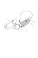
まず、図1および図2を参照して、本発明に従って構成されるカートリッジを着脱可能な電子写真画像形成装置の一実施例について説明する。本実施例の画像形成装置は、ホストコンピュータから画像情報を受け取り、画像出力するレーザービームプリンタであり、電子写真感光体である感光ドラムや、その他のプロセス手段、現像剤であるトナーなどの消耗品を一体的に構成しプロセスカートリッジとして電子写真画像形成装置本体に対して着脱交換可能とした電子写真画像形成装置である。 First, an embodiment of an electrophotographic image forming apparatus to which a cartridge constructed according to the present invention can be attached and detached will be described with reference to FIGS. The image forming apparatus of the present embodiment is a laser beam printer that receives image information from a host computer and outputs an image, and is a consumable item such as a photosensitive drum as an electrophotographic photosensitive member, other process means, and toner as a developer. Is an electrophotographic image forming apparatus that can be attached to and detached from the main body of the electrophotographic image forming apparatus as a process cartridge.
本実施例におけるプロセスカートリッジCは、感光ドラム1と、感光ドラム1を均一に帯電するための帯電手段である接触帯電ローラ2と、感光ドラム1に対向配置された現像手段としての現像ローラ5(以下現像スリーブ5と言う)と、現像スリーブ5に連結されトナーtを収容する現像剤収納部であるトナー容器4aとからなる現像装置4、クリーニングブレード10、およびクリーニングブレード10により感光体1から除去された残留トナーを収容する廃トナー容器11を備えたクリーニング手段6とが一体的に構成されている。
The process cartridge C in this embodiment includes a
帯電ローラ2は芯金の表面に導電性弾性体を形成したもので、芯金の両端部を回転自在に保持され、所定の押圧力にて感光ドラム1の外周面に圧接され、感光ドラム1の回転に従動回転する。帯電ローラ2には画像形成装置本体内に設けられた高圧電源から芯金を介して、帯電開始電圧の2倍以上のピーク間電圧Vppを有するAC成分VacとDC成分Vdcとの重畳電圧(Vac+Vdc)が帯電ローラ2に印加されて、回転駆動されている感光ドラム1の外周面がAC印加方式で均一に接触帯電処理される。
The
現像スリーブ5は、非磁性のアルミ製のスリーブ(ローラ)に樹脂層でコートされている。現像スリーブ5内には図示していないが4極のマグネットロールが配置されている。トナーtは現像スリーブ上に担持され、現像剤規制部材7により現像スリーブ5上に適正なコート量に規制される。
The developing
トナー容器4a内に収容されたトナーtは負帯電性磁性一成分トナーが用いられる。 As the toner t accommodated in the toner container 4a, a negatively chargeable magnetic one-component toner is used.
現像スリーブ5に印加される現像バイアスは、例えばDC電圧と矩形波のAC電圧の重畳電圧である。
The developing bias applied to the developing
また、トナー容器4a内にはトナー撹拌部材8があり、トナー容器4a内のトナーを攪拌し、ほぐしながら、現像スリーブ5近傍の現像領域にトナーを送り込んでいる。
A
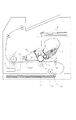
図2の本実施例のレーザービームプリンタにおいて、像担持体である円筒状の感光ドラム1は、その軸を中心に一方向に回転する。感光ドラム1は帯電ローラ2によってその表面を一様に帯電された後、露光装置(露光手段としての半導体レーザまたはLED等)3により静電潜像を形成される。感光ドラム1上に形成された静電潜像は現像装置4によりトナーtを供給してトナー像として可視化させる。現像スリーブ5にはバイアス供給電源(不図示)が接続されており、感光ドラム1と現像スリーブ5の間に上述した直流バイアスに交流バイアスを重畳した適正な現像バイアスを与えるようになっている。
In the laser beam printer of this embodiment shown in FIG. 2, the cylindrical
一方、給紙カセット20内に収容された記録媒体である転写材Pは、給紙ローラ21によって1枚ずつレジストローラ18まで送り出され、レジストローラ18によって感光ドラム1上の像と同期がとられて転写部に送られる。
On the other hand, the transfer material P, which is a recording medium accommodated in the
転写部において、トナーtにより可視化された感光ドラム1上のトナー像は転写ローラ9により転写材Pに転写される。転写材Pはさらに定着装置12に搬送され、トナー像が熱もしくは圧力により定着されて記録画像となる。
In the transfer portion, the toner image on the
転写後に転写されず感光ドラム1上に残ったトナーはクリーニングブレード10により除かれ廃トナー容器11に収容される。その後、感光ドラム1は再び帯電ローラ2によって帯電され上述の工程を繰り返す。
The toner that is not transferred after transfer but remains on the
つぎに、上記プロセスカートリッジ(以下、単に「カートリッジ」という)Cに装着される記憶手段(記憶媒体)としてのメモリ22について説明する。
Next, the
本実施例のカートリッジCは、廃トナー容器11の装着方向前面部に設けられたメモリ22と、メモリ22への情報の読み書きを制御するためのカートリッジ側伝達部23とを有している。このカートリッジ側伝達部とは送信されるデータをメモリ22に送信し、メモリ22に書き込む、またはメモリ22から読み出す機能を有している。このカートリッジ側伝達部23とメモリ22とは基板上に一体化されて構成されて、カートリッジCに装着されている。カートリッジCが画像形成装置本体に装着されると、カートリッジ側伝達部23と画像形成装置本体側の本体側伝達部14とが対向位置で接触するように配置されている。なお、本体側伝達部14は画像形成装置本体側の伝達手段としての機能し、画像形成装置本体の本体制御部24に接続されている。
The cartridge C of this embodiment includes a
本発明に使用されるメモリとしては、通常の半導体による電子的なメモリであれば特に制限なく使用することができる。メモリとして例えばEEPROM,FeRAMなどが使用可能である。 The memory used in the present invention can be used without particular limitation as long as it is an electronic memory using a normal semiconductor. For example, EEPROM, FeRAM or the like can be used as the memory.
上記記載はカートリッジ側伝達部23と本体側伝達部14が接触してデータ通信路を確立して読み出し/書き込みのデータ通信を行う場合であるが、非接触にしてデータ通信を電磁波によって行う場合こともできる。その場合には電磁波で通信するためのアンテナ部材(不図示)をカートリッジ側、画像形成装置本体側それぞれに設けて通信を行うようにすればよい。
The above description is a case where the cartridge-side transmission unit 23 and the main body-
これらのカートリッジ側伝達部23、本体側伝達部14、本体制御部24によってメモリ22内の情報の読み出しおよび書き込みを行うことが可能となる。メモリ22の容量については、後述するカートリッジ使用量およびカートリッジ特性値などの複数個の情報を記憶するのに十分な容量をもつものとする。
The cartridge side transmission unit 23, the main body
また、メモリ22には、カートリッジCの使用量情報が随時書き込み記憶される。メモリ22内に記憶されるカートリッジ使用量情報とは、画像形成装置本体によって判断できれば特に制限はない。例えば、感光ドラム1、帯電ローラ2、現像スリーブ5などの各ユニットの回転時間、帯電ローラ2、現像スリーブ5などへのバイアス印加時間、トナー残量、印字枚数、感光体に作像する画像ドット数、感光体を露光する際のレーザ発光時間の積算値、および感光体の膜厚、それぞれの使用量に重み付けを行って組み合わせた値、ぞれぞれの使用量を用いて演算した値などが挙げられる。
In addition, the usage amount information of the cartridge C is written and stored in the
さらに、カートリッジ出荷時におけるカートリッジの個々の特性に応じたカートリッジの特性値は、画像形成時のプロセス条件を変更するためのパラメータであり、工場出荷時にメモリ22に格納される。パラメータとしては、例えば、感光ドラムの製造ロットや帯電ローラの電気的な特性値、クリーニングブレードの当接圧などによって適正な値が記憶される。
Further, the characteristic value of the cartridge corresponding to the individual characteristic of the cartridge at the time of shipping the cartridge is a parameter for changing the process conditions at the time of image formation, and is stored in the
そして、メモリ22に格納されたこれらの情報に基づいて、本体制御部24によってプロセス条件が制御される。すなわち、メモリ22内の情報をカートリッジ側伝達部23、本体側伝達部14を介して本体制御部24が読み取って、本体制御部24においてその情報を用いて演算し、その演算結果に基づいてプロセス条件を変化させる。
Based on these pieces of information stored in the
本実施例では、同一の画像形成装置本体に着脱可能な異なる種類のカートリッジとして、感光ドラムの膜厚及び収容されるトナー容量の異なるカートリッジを用いる。 In this embodiment, cartridges having different film thicknesses of photosensitive drums and different toner capacities are used as different types of cartridges that can be attached to and detached from the same image forming apparatus main body.
まず、感光ドラムの感光層の膜厚の違いよる感光ドラムの潜像特性について説明する。 First, the latent image characteristics of the photosensitive drum depending on the film thickness of the photosensitive layer of the photosensitive drum will be described.
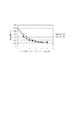
感光ドラムは感光層の膜厚の違いに応じて感光ドラムの持つ静電容量が異なるため、同じ暗部電位(−600V)を持つ感光ドラムに所定の露光量を当てた場合、明部電位は膜厚に応じて異なる。図3は感光層の膜厚が40μm、30μmの場合の露光量に対する明部電位の推移である。膜厚が薄くなると図3のドラム面でのレーザパワーが2.0mJ/m2付近の露光量の小さい領域で明部電位が高くなる。つまり、ハーフトーン等の中間調の画像では感光ドラムの膜厚の違いにより濃度が異なる。このように、感光体の感光層の膜圧の違いによって、同じ画像を形成した場合でも濃度が変動してしまうことが分かる。 Since the photosensitive drum has different electrostatic capacities depending on the film thickness of the photosensitive layer, when a predetermined exposure amount is applied to the photosensitive drum having the same dark portion potential (−600 V), the bright portion potential is the film thickness. It depends on the thickness. FIG. 3 shows the transition of the bright portion potential with respect to the exposure amount when the film thickness of the photosensitive layer is 40 μm and 30 μm. As the film thickness decreases, the bright portion potential increases in a region where the laser power on the drum surface in FIG. 3 is small and the exposure amount is near 2.0 mJ / m 2 . That is, in a halftone image such as a halftone, the density varies depending on the film thickness of the photosensitive drum. Thus, it can be seen that the density fluctuates even when the same image is formed due to the difference in the film pressure of the photosensitive layer of the photoreceptor.
同じ画像形成装置本体に感光ドラムの膜圧の異なる数種類のカートリッジを装着可能にする場合においては、異なる種類の全てのカートリッジを用いて画像形成を行った場合に同じ画像濃度であることが望ましいので、ドラム膜厚差によらず明部電位を適正化する必要がある。 When several types of cartridges having different film pressures of the photosensitive drum can be mounted on the same image forming apparatus main body, it is desirable that the same image density be obtained when image formation is performed using all the different types of cartridges. It is necessary to optimize the bright portion potential regardless of the drum film thickness difference.
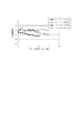
図4では、感光層の膜厚30μmの感光ドラムにおいて、帯電バイアスのDC電圧を変更して暗部電位を下げた場合の明部電位の推移である。図3と比較してわかるように膜厚の薄い感光ドラムに対しては暗部電位を下げることで、これらの明部電位が40μmの明部電位の推移に近くなり、ハーフトーン等の中間調の画像の濃度をほぼ同じにすることができる。よって、ドラム面でのレーザパワーが2.5〜3.5mJ/m2をべた濃度の明部電位に設定することで、感光層の膜厚差によるハーフトーン濃度、べた濃度差を小さくすることができる。 FIG. 4 shows the transition of the bright portion potential when the dark portion potential is lowered by changing the DC voltage of the charging bias in the photosensitive drum having a photosensitive layer thickness of 30 μm. As can be seen from the comparison with FIG. 3, by reducing the dark part potential for a thin photosensitive drum, the bright part potential becomes close to the transition of the bright part potential of 40 μm, and halftone and other halftones are obtained. The image density can be made substantially the same. Accordingly, by setting the laser power on the drum surface to 2.5 to 3.5 mJ / m 2 to a bright part potential with a solid density, the halftone density and solid density difference due to the film thickness difference of the photosensitive layer can be reduced. Can do.
ただし、暗部電位を下げすぎると現像電位との差(バックコントラスト)が小さくなることから、同じ現像コントラストでも濃度が高めになったり、かぶりと呼ばれる白地部にトナーが飛翔する量が多くなる。よって、濃度、かぶりが適正な範囲になるように現像バイアスのDC電圧を微調整してバックコントラストを大きくする必要がある。 However, if the dark portion potential is lowered too much, the difference from the development potential (back contrast) becomes small, so that the density increases even with the same development contrast, and the amount of toner flying to the white background portion called fog increases. Therefore, it is necessary to finely adjust the DC voltage of the developing bias so that the density and fog are in appropriate ranges, thereby increasing the back contrast.
また他の手段として、レーザの露光量を調整して明部電位を合わせることも可能である。 As another means, it is possible to adjust the light exposure potential by adjusting the exposure amount of the laser.
図3より、初期である40μmの膜厚において、2.7mJ/m2の露光量で明部電位を−160Vと設定している場合、30μmの膜厚時には3.1mJ/m2にの露光量にすることでほぼ同じ明部電位になり、ハーフトーン電位の差も小さくすることができる。 As shown in FIG. 3, when the light portion potential is set to −160 V with an exposure amount of 2.7 mJ / m 2 at an initial film thickness of 40 μm, the exposure is 3.1 mJ / m 2 when the film thickness is 30 μm. By setting the amount, the same bright portion potential is obtained, and the difference in halftone potential can be reduced.
次に、トナー容量が異なることで起きうる現像特性の変化を説明する。 Next, changes in development characteristics that may occur due to different toner volumes will be described.
図5はトナー容量が5000枚相当のSカートリッジ、10000枚相当のLカートリッジにおいて、感光ドラム使用量(プリント枚数)に応じた4dot(解像度600dpi設定)ラインのライン幅推移を示したものである。なお、ここでは、S、Lカートリッジはトナー容量のみが異なっている条件としている。
FIG. 5 shows the transition of the line width of a 4 dot (
使用初期はS、Lカートリッジともに同じライン幅推移であるが、その後において寿命の短いSカートリッジのライン幅の方が、寿命の長いLカートリッジよりは太り傾向は大きい。寿命の長いLカートリッジにおいてはライン幅の太り傾向はSカートリッジよりは小さいが、寿命後半でSカートリッジと同じ200μmの幅まで太くなる傾向はある。 In the initial stage of use, both the S and L cartridges have the same line width transition, but after that, the line width of the S cartridge having a short life is larger than that of the L cartridge having a long life. In the L cartridge having a long life, the line width tends to be thicker than that of the S cartridge, but in the latter half of the life, it tends to be thick up to the same width of 200 μm as the S cartridge.
トナー容量が小さいと攪拌部材による撹拌等によりトナーの循環が良いため、全体的にトナーが電荷を付与されるのが早くなり、トナー容量が多い場合に比べると、現像部にトナーが供給された時にはトナーの適度な電荷量までの立ち上がりが早くなり現像性が高くなる。よって、このようなSカートリッジでの現像特性から、Sカートリッジでは、Lカートリッジよりもライン幅の変化が大きくなるもの。一方、トナー容量の多いLカートリッジはトナーの電荷の立ち上がりが遅いのでSカートリッジよりもライン幅の太りは小さく、現像容器内の残トナー量が少なくなった頃にライン幅の太り変化が大きくなる。 When the toner capacity is small, the toner circulation is good due to stirring by the stirring member, etc., so that the toner is charged faster overall, and the toner is supplied to the developing unit as compared with the case where the toner capacity is large. Occasionally, the toner rises up to an appropriate charge amount, and developability increases. Therefore, because of the development characteristics of the S cartridge, the S cartridge has a larger change in line width than the L cartridge. On the other hand, the L cartridge with a large toner capacity has a slower toner charge rise, so the line width is smaller than that of the S cartridge, and the change in the line width increases as the amount of residual toner in the developing container decreases.
このように、充填されたトナー量の違いで現像特性が異なるので、トナー量の違い応じた制御を行い現像性を安定させるのが良い。 As described above, since the development characteristics differ depending on the amount of filled toner, it is preferable to stabilize the developability by performing control according to the difference in toner amount.
その手段としては、帯電、現像バイアスのACまたはDC電圧を変化させたり、レーザ露光量を調整する方法がある。 As the means, there are methods of changing the AC or DC voltage of charging and developing bias, and adjusting the laser exposure amount.
また、この現像性を安定させるための制御を行うためには、トナーの消費量を推定できる感光ドラム上に作像した像に対する画像情報の累積ドット数で行うことも可能であるし、あるいはプリント枚数や、後述するカートリッジが駆動した時間と係数情報によるカートリッジの使用量を用いることができる。画像情報の累積ドット数、または、プリント枚数、カートリッジ使用量が所定値(所定の閾値情報)に到達したタイミングで帯電、現像バイアス、レーザ露光量を調整するよう制御すれば良い。 In addition, in order to perform control for stabilizing the developability, it is possible to use the cumulative number of dots of image information for an image formed on the photosensitive drum capable of estimating the toner consumption amount, or print. It is possible to use the number of cartridges and the amount of cartridge used based on the time and coefficient information of the cartridge that will be described later. It may be controlled to adjust the charging, developing bias, and laser exposure amount at the timing when the cumulative number of dots of image information, the number of prints, and the cartridge usage amount reach a predetermined value (predetermined threshold information).
本実施例では、上述したカートリッジの種類に応じた潜像特性や現像特性の違いを調整するために、カートリッジの使用量に係わる情報を用いて、下記のような制御を行う。
(1)カートリッジCにメモリ22を備え、カートリッジの種類に係わる情報を記憶させておく。
(2)メモリ22にカートリッジCが画像形成装置本体内で駆動された時間を記憶する。
(3)感光ドラム1とクリーニングブレード10の当接圧、帯電ローラ2の電気特性によって決まる演算式の係数情報と、プロセス条件を切り替えるタイミングとしての閾値情報と、を製造時にメモリ22に記憶させておく。
(4)画像形成装置本体において、カートリッジの種類を識別し、カートリッジCのメモリ22に記憶されている駆動時間と係数情報によってカートリッジCの使用量(例えば、感光ドラム1の使用量)を計算し、その計算値と、カートリッジCのメモリ22に記憶されている、予め感光ドラム1の感光材料の特性によって決定される上記使用量に関する閾値情報と比較する。そして計算値が閾値となった時にプロセス条件を変更する。
In this embodiment, in order to adjust the difference in latent image characteristics and development characteristics according to the type of cartridge described above, the following control is performed using information relating to the amount of cartridge used.
(1) The cartridge C includes a
(2) The
(3) Coefficient information of an arithmetic expression determined by the contact pressure between the
(4) In the main body of the image forming apparatus, the type of the cartridge is identified, and the amount of use of the cartridge C (for example, the amount of use of the photosensitive drum 1) is calculated based on the drive time and coefficient information stored in the
ここで、カートリッジCのメモリ22に記憶されている閾値情報は複数設定して、露光量、帯電/現像バイアスの切り替えを複数回行ってもよい。このことにより、感光ドラム1の使用期間を通して安定した明部電位を得ることが可能となり、形成画像の高画質化(画質の安定化)が実現できる。また、変更するプロセス条件の設定に関する情報とともに、この閾値情報をカートリッジのメモリ22に記憶させても良い。
Here, a plurality of threshold information stored in the
図6および図7によって、本実施例における特徴部分の構成について具体的に説明する。 The configuration of the characteristic part in the present embodiment will be specifically described with reference to FIGS.
本実施例では、カートリッジ使用量に係わる情報として感光ドラム回転時間をもとに算出した感光ドラム使用量情報を用いた。これは特登録3285785で開示されている感光ドラムのダメージ指数に基づき演算される感光ドラムの使用量に相当する。 In this embodiment, the photosensitive drum usage information calculated based on the photosensitive drum rotation time is used as the information related to the cartridge usage. This corresponds to the usage amount of the photosensitive drum calculated based on the damage index of the photosensitive drum disclosed in Japanese Patent No. 3285785.
図6に示すように、本体制御部24では、データ記憶用メモリ13、制御部25、演算部26、感光体回転指示部27、帯電バイアス印加時間検出部28、および本体伝達部14などからなり、バイアス供給電源29と接続されている。また、カートリッジCにはメモリ22と伝達部23が配置されている。
As shown in FIG. 6, the main
また、図7に示すように、カートリッジC内のメモリ22にはカートリッジ駆動時間情報T、感光ドラム使用量を演算するための重み付け係数であるドラム使用量演算式係数情報φ、感光ドラム使用量閾値情報α、感光ドラム使用量閾値情報に対応して画像形成条件を設定するためのテーブルを示す情報などの情報が格納されている。なお、ドラム使用量閾値情報αとドラム使用量演算式係数情報φはカートリッジCの出荷時にメモリ22に記憶される。これらの値は、ドラム感度やドラム材料、クリーニングブレードの当接圧、帯電ローラの電気的特性によって変化するため、カートリッジCの個々にメモリに記憶されて出荷される。
Further, as shown in FIG. 7, the
つぎに、本実施例の制御動作について説明する。 Next, the control operation of this embodiment will be described.
プリント信号を画像形成装置本体が受けると感光体回転指示部27によってカートリッジCが駆動され、画像形成プロセスが開始される。この際、以下のようにドラム使用量を算出する。 When the main body of the image forming apparatus receives the print signal, the cartridge C is driven by the photosensitive member rotation instruction unit 27, and the image forming process is started. At this time, the drum usage is calculated as follows.
感光体回転指示部27からの感光ドラム回転時間データ(上記カートリッジ駆動時間情報Tに相当)を積算した値Bと、帯電バイアス印加時間検出部28からの帯電バイアス印加時間データを積算した値Aと、メモリ22から読み出された重み付け係数φを用いた換算式D=A+B×φにより演算部26でドラム使用量Dが計算され、本体データ記憶用の本体メモリ13に積算記憶される。積算記憶されたドラム使用量Dは演算部26により、画像形成装置本体内のメモリ13内の閾値αと比較される。比較の結果、ドラム使用量Dが閾値αより大きくなった時に、制御部25からバイアス供給電源部29内の高圧回路部(不図示)に制御信号が送られ帯電/現像バイアスのDC電圧が変更される。
A value B obtained by integrating photosensitive drum rotation time data (corresponding to the cartridge driving time information T) from the photoconductor rotation instruction unit 27, and a value A obtained by integrating charging bias application time data from the charging bias application
感光ドラム回転時間データと帯電バイアス印加時間データは随時メモリ22に格納され、ドラム使用量のデータの演算は、感光ドラム1の駆動が停止した際に随時行われる。
The photosensitive drum rotation time data and the charging bias application time data are stored in the
なお、感光ドラム回転時間データや帯電バイアス印加時間データをメモリ22に記憶するかわりに、演算した結果のドラム使用量Dをメモリ22に書き込んでも良い。
Instead of storing the photosensitive drum rotation time data and charging bias application time data in the
本実施例では、上述した感光ドラムの膜厚に依存する感光ドラムの潜像特性と、トナー容量に依存する現像特性を考慮した複数のプロセス条件のセットであるテーブルを複数設けて、カートリッジの種類、使用量の状況に応じて複数のテーブルから一つを選択して、プロセス条件を設定するようにした。 In this embodiment, a plurality of tables, each of which is a set of a plurality of process conditions considering the latent image characteristics of the photosensitive drum depending on the film thickness of the photosensitive drum and the development characteristics depending on the toner capacity, are provided. The process conditions are set by selecting one from a plurality of tables according to the usage status.
本実施例でのプロセス条件の組み合わせとしては、
(1)露光量と帯電/現像バイアス
主に、潜像特性:露光量、現像特性:帯電/現像DC電圧で制御する。あるいは、潜像特性:帯電/現像DC電圧、現像特性:露光量で制御する。
(2)帯電/現像バイアスのみ
潜像特性、現像特性:ともに帯電、現像DC電圧で制御する。
が可能である。
As a combination of process conditions in this embodiment,
(1) Exposure amount and charging / development bias Mainly controlled by latent image characteristics: exposure amount, development characteristics: charging / development DC voltage. Alternatively, control is performed using latent image characteristics: charging / developing DC voltage and developing characteristics: exposure amount.
(2) Charging / development bias only Latent image characteristics and development characteristics: Both are controlled by charging and developing DC voltage.
Is possible.
上記プロセス条件の組み合わせについて順に詳細に説明する。 The combination of the process conditions will be described in detail in order.
(実施形態1)
露光量と帯電/現像バイアスで制御する場合
トナー容量と感光ドラムの感光層の膜厚が異なる以下のカートリッジCにおいて、例を挙げる。
Sカートリッジ;トナー容量5000枚(5%印字)相当、感光層の膜厚 30μm
Lカートリッジ;トナー容量10000枚(5%印字)相当、感光層の膜厚 40μm
潜像特性においては、感光層の消耗量により、表1のように4段階に露光量を切り替えられるようにし、現像特性においては、3段階に帯電DC電圧現像DC電圧を切り替えられるようにした。
(Embodiment 1)
When Controlled by Exposure Amount and Charging / Developing Bias An example is given in the following cartridge C in which the toner capacity and the photosensitive layer thickness of the photosensitive drum are different.
S cartridge; toner capacity equivalent to 5000 sheets (5% printing), photosensitive layer thickness 30 μm
L cartridge; equivalent to 10,000 toner capacity (5% printing), photosensitive layer thickness 40 μm
In the latent image characteristics, the exposure amount can be switched in four stages as shown in Table 1 depending on the consumption amount of the photosensitive layer, and in the development characteristics, the charging DC voltage development DC voltage can be switched in three stages.

この帯電DC電圧、現像DC電圧の切替については、図8のように濃度調整を帯電、現像バイアスのDC電圧の変化で行う場合、Default設定値(濃度設定値)だけでなく、その上限(濃度濃い側)、下限(濃度低い側)の電圧設定も含めた表2の3通りを用意した。 As for the switching of the charging DC voltage and the developing DC voltage, when density adjustment is performed by changing the DC voltage of charging and developing bias as shown in FIG. 8, not only the default setting value (density setting value) but also its upper limit (density) The three types shown in Table 2 including the voltage settings for the dark side and the lower limit (low concentration side) were prepared.
以上、S、Lカートリッジの潜像特性、現像特性の違いによる濃度、ライン幅の推移から、表3のような露光量、帯電DC電圧、現像DC電圧設定の組み合わせとして、7つの組み合わせからなるテーブルを用意した。 As described above, the table of seven combinations as combinations of exposure amount, charging DC voltage, and development DC voltage setting as shown in Table 3 from the transition of density and line width due to differences in latent image characteristics and development characteristics of S and L cartridges. Prepared.
ここで、通紙枚数による感光ドラムの摩耗スピード(摩耗度合い)を確認したところ、S、Lカートリッジともに、1枚/jobのモードで1μm/1000枚であった。 Here, the wear speed (wear level) of the photosensitive drum according to the number of sheets passed was confirmed. As a result, both the S and L cartridges were 1 μm / 1000 sheets in the 1 sheet / job mode.
そして、ドラム使用量は1枚プリントで、
帯電バイアス印加時間データを積算した値A=10、
感光ドラム回転時間データを積算した値B=5、
重み付け係数φ=2、となり
1枚プリントにおけるドラム使用量D=20(10+5×2)となる。
And the drum usage is one sheet print,
A value A = 10 obtained by integrating charging bias application time data,
Value B = 5 obtained by integrating photosensitive drum rotation time data,
The weighting coefficient φ = 2, and the drum usage D per sheet print D = 20 (10 + 5 × 2).
これらより、通紙枚数による感光ドラムの摩耗量、現像特性より、図9のような閾値情報αの設定と選択するテーブルを決めた。 From these, the table for selecting and setting the threshold information α as shown in FIG. 9 is determined from the wear amount of the photosensitive drum depending on the number of sheets to be passed and the development characteristics.
図9(a)は表3のテーブルの切り替えタイミングとその選択するテーブル設定を示しており、図9(b)はその切り替えタイミングの詳細情報である。図9(a)に示されるようにSカートリッジとLカートリッジとで異なるタイミングで異なるテーブルを選択してプロセス条件を設定するために、SカートリッジとLカートリッジに設けられたメモリの記憶内容は図16に示されるような構成となる。 FIG. 9A shows the switching timing of the table of Table 3 and the table setting to be selected, and FIG. 9B shows detailed information of the switching timing. As shown in FIG. 9A, in order to select different tables at different timings for the S cartridge and the L cartridge and set the process conditions, the storage contents of the memory provided in the S cartridge and the L cartridge are as shown in FIG. It becomes a structure as shown in.
Sカートリッジ、Lカートリッジのそれぞれに設けられたメモリには、それぞれ記憶領域S01〜S10、L01〜L12が設定されている。記憶内容は以下のとおりである。
S01、L01:SカートリッジかLカートリッジかを示すカートリッジ種類情報
S02、L02:カートリッジを用いて印字した際の感光ドラムの回転時間情報
S03、L03:カートリッジを用いて印字した際の帯電手段(帯電ローラ2)に帯電バイアスを印加した印加時間情報
S04、L04:感光ドラムの使用量演算に用いる演算係数情報
S05、L05:カートリッジが未使用であることを示す情報
S06,L06:カートリッジ使用初期のプロセス条件を設定するための情報(表3の値)
S07、S09、L07、L09、L11:感光ドラム使用量の閾値情報(感光ドラム使用量がこの閾値情報に達した場合にプロセス条件を切り替える)
S08、S10、L08、L10、L12:感光ドラムの使用量に応じたプロセス条件を選択するための情報(表3の値であり閾値情報に対応して記憶されている)。
Storage areas S01 to S10 and L01 to L12 are set in the memories provided in the S cartridge and the L cartridge, respectively. The stored contents are as follows.
S01, L01: Cartridge type information S02 indicating whether the cartridge is an S cartridge or L cartridge, L02: Rotating time information of the photosensitive drum when printing is performed using the cartridge, S03, L03: Charging means (printing roller when printing is performed using the cartridge) 2) Application time information S04, L04 when charging bias is applied: Calculation coefficient information S05, L05: Information indicating that the cartridge is not used S06, L06: Process conditions at the beginning of cartridge use For setting the value (value in Table 3)
S07, S09, L07, L09, L11: Photosensitive drum usage threshold information (switches process conditions when the photosensitive drum usage reaches this threshold information)
S08, S10, L08, L10, L12: Information for selecting a process condition corresponding to the usage amount of the photosensitive drum (the values in Table 3 are stored corresponding to the threshold information).
SカートリッジとLカートリッジではカートリッジの構成は同一であるが、前記したとおり、トナー容量と感光ドラムの膜厚がそれぞれ異なる。Sカートリッジはトナー容量が5000枚(A4:5%印字)相当の容量、感光ドラムの膜厚は30μmであり、Lカートリッジはトナー容量が10000枚(A4:5%印字)相当の容量、感光ドラムの膜厚は40μmである。 Although the cartridge configuration of the S cartridge and the L cartridge is the same, as described above, the toner capacity and the film thickness of the photosensitive drum are different. The S cartridge has a toner capacity equivalent to 5000 sheets (A4: 5% printing), the film thickness of the photosensitive drum is 30 μm, and the L cartridge has a toner capacity equivalent to 10,000 sheets (A4: 5% printing), a photosensitive drum. The film thickness is 40 μm.
そして図9に示されているように各カートリッジで感光ドラムの使用量に応じてプロセス条件(露光条件、帯電・現像条件)を変更する。 Then, as shown in FIG. 9, the process conditions (exposure conditions, charging / developing conditions) are changed in accordance with the usage amount of the photosensitive drum in each cartridge.
つぎに、図16と図10のフローチャートを用いて本実施例の画像形成装置の動作を説明する。
START:制御開始
S101:画像形成装置本体の電源ON。
S102:本体の制御部24が装着されたカートリッジCの種類を認識する。(メモリ22の記憶領域S01(Lカートリッジの場合はL01)に記憶されている情報を読み出して、Sカートリッジ、Lカートリッジのどちらかを認識し、例えば画像形成装置本体のオペレーションパネルなどにカートリッジの種類を表示するなどする。)
S103:次に、メモリ22の記憶領域S05からカートリッジが未使用かどうかを示す未使用情報を読み出し、未使用であることを示している場合には、その情報を使用済みであることを示す情報に更新する。そして、メモリ22の記憶領域S06から使用開始時のプロセス条件を設定するための情報cを読み出す。このcは表3で示されているテーブル内のデータであり、この場合はcに対応するプロセス条件を使用開始時のプロセス条件として設定する。なお、cはカートリッジ使用開始時の値としてメモリ13に記憶される。S104:本体制御部24がメモリ22の記憶領域S07(Lカートリッジの場合はL07)に記憶されている閾値情報αsiを読み出し、読み出した閾値情報を制御部24のメモリ13に記憶する。(iの初期値は1)
S105:カートリッジCのメモリ22の記憶領域S02、S03(Lカートリッジの場合はL02、L03)からこれまでの感光体回転時間と帯電バイアス印加時間の積算値情報を読み出す。
S106:その後画像形成装置はプリントレディ状態(プリント信号受付可能な状態)になりプリント信号の受信を待機している。
S107:プリント信号ON。
S108:感光体回転時間検出部27が回転時間のカウントを開始してメモリ22から読み出された感光体回転時間に積算する。
S109:帯電バイアス印加時間検出部28が、帯電バイアス印加時間のカウントを開始してメモリ22から読み出された帯電バイアス印加時間に積算する。
S110:プリント終了。
S111:カートリッジのメモリ22の記憶領域S04(Lカートリッジの場合はL04)から重み付け係数φを読み出す。
S112:演算部26にて、S108、S109で積算された感光ドラム回転時間と帯電バイアス印加時間と、メモリ22から読み出した重み付け係数φとを用いてドラム使用量Dを計算する。
S113:本体制御部24内のメモリ13より閾値情報αsiを読み出す。
S114:演算部26が、ドラム使用量データDと、ドラム使用量演算式閾値αsiを比較する。すなわち、D>αsiかどうかを判断する。“YES”と判断された場合には、S115に進み、“NO”と判断された場合には、ステップS105に戻り、制御を繰り返す。
S115:カートリッジのメモリ22の記憶領域S08(Lカートリッジの場合はL08)より、ドラム使用量演算式閾値αs1に対応したテーブル設定値dを読み出して、表3のテーブル設定値dに基づいて、プロセス条件(露光量、帯電・現像DC電圧)が切り替えられる。ここで、S103においてメモリ13に記憶されたcの値をこのd値に書き換えて記憶する。(設定値が切り替わるごとにメモリ13を書き換える。)
S116:i=i+1として、S106に戻り、制御を繰り返す。
Next, the operation of the image forming apparatus of this embodiment will be described with reference to the flowcharts of FIGS.
START: Start of control S101: The image forming apparatus main body is turned on.
S102: Recognize the type of cartridge C in which the
S103: Next, unused information indicating whether or not the cartridge is unused is read from the storage area S05 of the
S105: The integrated value information of the photosensitive member rotation time and the charging bias application time so far is read from the storage areas S02 and S03 of the
S106: Thereafter, the image forming apparatus is in a print ready state (a state in which a print signal can be received) and is waiting to receive a print signal.
S107: Print signal ON.
S108: The photoconductor rotation time detection unit 27 starts counting the rotation time and integrates it with the photoconductor rotation time read from the
S 109: The charging bias
S110: End of printing.
S111: The weighting coefficient φ is read from the storage area S04 of the cartridge memory 22 (L04 in the case of the L cartridge).
S 112: The
S113: The threshold information αsi is read from the
S114: The
S115: The table setting value d corresponding to the drum usage amount calculation formula threshold value αs1 is read from the storage area S08 of the
S116: Set i = i + 1, return to S106, and repeat the control.
S、Lカートリッジそれぞれにおいて、2%印字率の画像、かつ、1枚/jobの条件で印字して、所定枚数毎に画像の評価を行った。(プリント枚数:0〜15000枚)
図11は孤立1dotで形成された印字率25%のハーフトーン画像での濃度推移である。図12は4dot(解像度600dpi設定)ライン幅の推移である。それぞれ、カートリッジの種類差なく、寿命を通して安定したハーフトーン濃度、ライン幅を示し、カブリのない高画質な画像を得ることを確認した。
In each of the S and L cartridges, an image having a printing rate of 2% was printed under the condition of 1 sheet / job, and the image was evaluated for each predetermined number of sheets. (Number of prints: 0 to 15000)
FIG. 11 is a density transition in a halftone image formed at an isolated 1 dot and having a printing rate of 25%. FIG. 12 shows the transition of 4 dot (
なお、1000枚プリント毎に印字率25%のハーフトン画像を印字して濃度推移を確認し、1000枚プリント毎に4dotライン幅の画像を印字してライン幅推移を確認している。 A halftone image with a printing rate of 25% is printed every 1000 prints to check the density transition, and an image with a 4-dot line width is printed every 1000 prints to check the line width change.
また、Sカートリッジ、Lカートリッジそれぞれのドラム使用量に応じて選択する表3のテーブルの値(a〜g)は、Sカートリッジ、Lカートリッジで各々独立した設定になっているが、設定する感光ドラムの膜厚やトナー容量、それに応じた濃度、ライン幅の推移状況によっては同じテーブルの値に設定されることもあり得る。例えば、テーブル設定のc=fとなることもあり得る。 Further, the table values (a to g) selected in accordance with the drum usage amount of each of the S cartridge and the L cartridge are set independently for the S cartridge and the L cartridge. The values in the same table may be set depending on the film thickness, toner capacity, density corresponding to the film thickness, and the transition state of the line width. For example, c = f may be set in the table setting.
また、テーブルを切り替える閾値情報もSカートリッジ、Lカートリッジで各々独立はしているが、感光ドラムの削れ量がS、Lカートリッジでともに同じである場合もあるので、(異なる場合もあるが)、同じ閾値情報でテーブル設定の選択切り替えが行われることもある。 The threshold information for switching the table is also independent for the S cartridge and the L cartridge, but the amount of photoconductor drum wear may be the same for both the S and L cartridges (though it may be different). The table setting selection switching may be performed with the same threshold information.
なお、図16におけるカートリッジCの構成は前述しているので説明を省略する。 Since the configuration of the cartridge C in FIG. 16 has been described above, the description thereof will be omitted.
(実施形態2)
帯電/現像バイアスのみで制御
本実施形態では、実施形態1で述べたような上限、下限設定も含めた帯電/現像バイアスのDC電圧設定を切り替えることによって、種類の異なるカートリッジの潜像特性、現像特性の違いによる濃度、ライン幅の変動を抑制する。
(Embodiment 2)
Control only by charging / developing bias In this embodiment, the latent image characteristics and development of different types of cartridges are switched by switching the DC voltage setting of charging / developing bias including the upper limit and lower limit setting as described in the first embodiment. Suppresses fluctuations in density and line width due to differences in characteristics.
本実施例で用いたカートリッジCは、実施例1のS、Lのカートリッジと同じ構成であるが、それぞれのカートリッジのメモリ22に記憶される情報が異なる。
The cartridge C used in the present embodiment has the same configuration as the cartridges S and L in the first embodiment, but the information stored in the
本実施形態では、感光ドラムの感光層の膜厚に応じたドラム使用量の閾値情報によって、潜像電位が同じになるように帯電バイアスのDC電圧を小さくする。そして、帯電バイアスのDC電圧の変更にあわせてカブリが発生しないようバックコントラストがある程度確保できるように現像バイアスのDC電圧も小さくするように設定する。帯電バイアスDC電圧と現像バイアスDC電圧の設定として表4のような濃度上限、下限も含めた設定を3通り((I)〜(III)の表)用意する。 In this embodiment, the DC voltage of the charging bias is reduced so that the latent image potentials are the same based on the threshold information of the drum usage amount corresponding to the film thickness of the photosensitive layer of the photosensitive drum. Then, the DC voltage of the developing bias is set to be small so that the back contrast can be secured to some extent so as not to cause fogging in accordance with the change of the DC voltage of the charging bias. As the setting of the charging bias DC voltage and the developing bias DC voltage, three kinds of settings including the upper limit and the lower limit of density as shown in Table 4 (tables (I) to (III)) are prepared.
そして、現像特性の補正の仕方としては、表4の(I)〜(III)から選択された帯電/現像バイアスのDC設定の中で、濃度のDefault設定値(濃度設定値)を変えて行う。例えば図13のように上限から下限までのバイアスの設定が10段階に分けられて選択できるようにする。通常のDefault設定(濃度設定)は5の設定であるが、例えば現像特性上ラインが細めにあるときには、濃度が高くなる側の3のDC電圧設定にし、現像性が上がってきたら5の設定に選択できるようにして、現像性を安定させる。 The developing characteristics are corrected by changing the density default setting value (density setting value) in the DC setting of the charging / developing bias selected from (I) to (III) in Table 4. . For example, as shown in FIG. 13, the setting of the bias from the upper limit to the lower limit can be selected in 10 stages. The normal default setting (density setting) is 5; however, for example, when the line is narrow due to development characteristics, the DC voltage setting of 3 on the higher density side is set. The developability is stabilized by allowing selection.
以上、S、Lカートリッジの潜像、現像特性の違いによる濃度、ライン幅の推移から、表5のようなDC電圧設定と濃度のDefault設定(濃度設定)との6つの組み合わせからなるテーブルを用意した。電圧の濃度設定は上述したように、上限(濃度が高い側)設定を0、下限(濃度が低い側)設定を10として、0〜10の期間で均等配分した設定値の中から選択した。 As described above, a table comprising six combinations of DC voltage setting and density default setting (density setting) as shown in Table 5 is prepared based on changes in latent images of S and L cartridges, density and line width due to differences in development characteristics. did. As described above, the voltage density setting was selected from set values that were uniformly distributed over a period of 0 to 10, with the upper limit (higher density side) setting being 0 and the lower limit (lower density side) setting being 10.
例えば、Sカートリッジにおいて、帯電/現像バイアスのDC電圧の濃度Default設定(濃度設定)は表6のようになる。 For example, in the S cartridge, the density default setting (density setting) of the DC voltage of the charging / developing bias is as shown in Table 6.
ドラム使用量が閾値情報αs1に達すると、図5のSカートリッジの現像特性によりトナー現像性が高くなる(立ち上がりが早くなる)ことによるライン幅の増加を抑えるために、テーブル設定がj→kに設定が切り替わり、同じDC設定(II)の中で濃度Default設定(濃度設定)が5→7になる。 When the drum usage amount reaches the threshold information αs1, the table setting is changed from j to k in order to suppress an increase in the line width due to an increase in toner developability due to the development characteristics of the S cartridge in FIG. The setting is switched, and the density default setting (density setting) is changed from 5 to 7 in the same DC setting (II).
そして、ドラム使用量が閾値情報αs2に達すると、テーブル設定がk→lに設定が切り替わる。主に感光ドラムの感光層膜厚減による潜像特性を補正するため、(III)のDC設定に切り替えが行われ、更にライン幅の変動の微調補正をするために濃度Default設定(濃度設定)を6にした。 When the drum usage reaches the threshold information αs2, the table setting is switched from k → l. In order to correct the latent image characteristic mainly due to the reduction in the photosensitive layer thickness of the photosensitive drum, the DC setting in (III) is switched, and the density default setting (density setting) is used to finely correct the line width variation. Was set to 6.
このように、カートリッジの潜像特性を補正するため、そして、感光ドラム使用量に応じてバックコントラストを確保するために、帯電バイアス及び現像バイアスのDC電圧のテーブル(I)〜(III)を設定し、それぞれのテーブルにおいて、現像特性を補正するために濃度設定値のDefault値を変更するように設定している。 Thus, in order to correct the latent image characteristics of the cartridge and to ensure the back contrast according to the amount of photosensitive drum used, the charging bias and developing bias DC voltage tables (I) to (III) are set. In each table, the default value of the density setting value is set to be changed in order to correct the development characteristics.
そして、図9(b)に示されているのと同様の切り替えタイミングで、図14に示されているのような制御を行ったところ、実施例1と同様な効果が得られた。 Then, when the control as shown in FIG. 14 was performed at the same switching timing as shown in FIG. 9B, the same effect as in Example 1 was obtained.
図17は本実施形態におけるS,Lカートリッジそれぞれのメモリ22の記憶内容の構成を示している。記憶領域の構成は実施例1(図16)の構成とほぼ同様であるが、閾値情報α(記憶領域S05、S07)の値とそれに対応して記憶されている設定値(記憶領域S06、S08、S10、L06、L08、L10、L12)が実施例1とは異なっている。
FIG. 17 shows the configuration of the contents stored in the
なお、本実施例における画像形成動作の制御については実施例1の図10のフローチャートに示されている制御と同様であるため説明は省略する。 The control of the image forming operation in the present embodiment is the same as the control shown in the flowchart of FIG.
なお、図17におけるカートリッジCの構成は前述しているので説明を省略する。 Note that the configuration of the cartridge C in FIG.
なお、上記実施形態1、実施形態2では図16及び図17で示したように、感光ドラム回転時間情報、帯電バイアス印加時間情報を別々に更新記憶する構成で説明した。しかし、これに限らず、感光ドラム回転時間情報と帯電バイアス印加時間情報とを夫々記憶するのではなく、感光ドラム回転時間情報と帯電バイアス印加時間情報と用いて演算した感光体の使用量の情報(D)を更新記憶する構成においても同様の効果を得ることができる。 In the first embodiment and the second embodiment, as shown in FIGS. 16 and 17, the photosensitive drum rotation time information and the charging bias application time information are separately updated and stored. However, the present invention is not limited to this, and the photosensitive drum rotation time information and the charging bias application time information are not stored separately, but the usage amount information of the photoconductor calculated using the photosensitive drum rotation time information and the charging bias application time information. The same effect can be obtained in the configuration in which (D) is updated and stored.
以上のように、本実施例によれば、感光ドラムの膜厚、充填されるトナー容量が異なる複数種類のカートリッジを同一の画像形成装置本体に用いた場合でも、濃度、ライン幅のばらつきを低減することが可能となる。つまり、同じ感光ドラム使用量のタイミングで異なるプロセス制御を行うことで、その種類の差による画質のバラツキ、特に濃度、ライン幅のばらつきを抑えることができるとともに、使用開始から寿命までを通して画質を安定させることができる。 As described above, according to this embodiment, even when a plurality of types of cartridges having different photosensitive drum thicknesses and filled toner capacities are used in the same image forming apparatus main body, variations in density and line width are reduced. It becomes possible to do. In other words, by performing different process control at the same photosensitive drum usage timing, it is possible to suppress variations in image quality due to the difference in type, especially variations in density and line width, and to stabilize image quality from the start of use to the end of its service life. Can be made.
1 感光ドラム
2 帯電ローラ
3 露光装置
4 現像装置
4a 現像容器
5 現像スリーブ
6 クリーニング装置
7 現像規制部材
8 攪拌部材
9 転写ローラ
10 クリーニングブレード
11 廃トナー容器
12 定着装置
13 メモリ
14 本体側伝達部
18 レジストローラ
20 給紙カセット
21 給紙ローラ
22 メモリ
C プロセスカートリッジ
P 転写材
t トナー
DESCRIPTION OF
Claims (19)
前記カートリッジの複数の特性に応じて画像形成条件を設定するための複数の設定情報を記憶する記憶部と、
前記複数種類の各カートリッジの使用量に係わる情報と前記カートリッジの記憶媒体に記憶される前記設定情報を選択するための情報とに基づいて、前記画像形成条件を設定する制御部とを有することを特徴とする画像形成装置。 An image forming apparatus in which a plurality of types of cartridges including a plurality of process members used for image formation and a storage medium for storing information are detachable,
A storage unit for storing a plurality of setting information for setting image forming conditions according to a plurality of characteristics of the cartridge;
A controller configured to set the image forming condition based on information on the usage amount of each of the plurality of types of cartridges and information for selecting the setting information stored in a storage medium of the cartridge. An image forming apparatus.
前記制御部は、前記複数の設定情報を選択するための情報と前記しきい値情報と、前記複数種類の各カートリッジの使用量に係わる情報と、に応じて前記画像形成条件を設定することを特徴とする請求項1に記載の画像形成装置。 The storage medium further stores threshold information on the usage amount of the cartridge,
The control unit sets the image forming condition in accordance with information for selecting the plurality of setting information, the threshold information, and information on the usage amount of each of the plurality of types of cartridges. The image forming apparatus according to claim 1, wherein:
前記しきい値情報とは、前記像担持体の回転時間、前記帯電部材へのバイアス印加時間のいずれかを含むこと特徴とする請求項2に記載の画像形成装置。 The process member includes an image carrier and a charging member for charging the image carrier,
The image forming apparatus according to claim 2, wherein the threshold information includes any one of a rotation time of the image carrier and a bias application time to the charging member.
前記複数の設定情報とは、前記帯電部材、または現像部材へ印加されるバイアス、または前記像担持体へ露光する露光量に関わる情報を含むことを特徴とする請求項1または2に記載の画像形成装置。 The process member includes an image carrier, a charging member for charging the image carrier, and a developing member for developing a latent image formed on the image carrier,
3. The image according to claim 1, wherein the plurality of setting information includes information related to a bias applied to the charging member or the developing member or an exposure amount to be exposed to the image carrier. Forming equipment.
前記制御部は前記演算係数情報を用いて前記カートリッジの使用量を演算することを特徴とする請求項1〜4のいずれかに記載の画像形成装置。 The storage medium further stores calculation coefficient information,
The image forming apparatus according to claim 1, wherein the control unit calculates a usage amount of the cartridge using the calculation coefficient information.
像担持体と、
前記像担持体に作用する複数のプロセス部材と、
前記カートリッジの複数の特性に応じて画像形成条件を設定するための複数の設定情報を選択するための情報を記憶する記憶領域を有する記憶媒体と、を有することを特徴とするカートリッジ。 A cartridge detachable from the image forming apparatus,
An image carrier;
A plurality of process members acting on the image carrier;
And a storage medium having a storage area for storing information for selecting a plurality of setting information for setting image forming conditions according to a plurality of characteristics of the cartridge.
前記複数の設定情報とは、前記帯電部材、または現像部材へ印加されるバイアス、あるいは前記像担持体へ露光する露光量に関わる情報であることを特徴とする請求項7または8に記載のカートリッジ。 The process member includes a charging member for charging the image carrier and a developing member for developing a latent image of the image carrier,
9. The cartridge according to claim 7, wherein the plurality of setting information are information related to a bias applied to the charging member or the developing member or an exposure amount to be exposed to the image carrier. .
前記カートリッジは、像担持体と、前記像担持体に作用する複数のプロセス部材と、を含み、
前記記憶媒体は、
前記カートリッジの複数の特性に応じて画像形成条件を設定するための複数の設定情報を選択するための情報を記憶する記憶領域を有することを特徴とする記憶媒体。 A storage medium mounted on a cartridge used in an image forming apparatus,
The cartridge includes an image carrier, and a plurality of process members that act on the image carrier,
The storage medium is
A storage medium having a storage area for storing information for selecting a plurality of setting information for setting image forming conditions according to a plurality of characteristics of the cartridge.
前記カートリッジの使用量のしきい値情報とは、前記像担持体の回転時間、前記帯電手段へのバイアス印加時間のいずれかを含むこと特徴とする請求項14に記載の記憶媒体。 The process member includes a charging member for charging the image carrier,
15. The storage medium according to claim 14, wherein the threshold information of the usage amount of the cartridge includes any one of a rotation time of the image carrier and a bias application time to the charging unit.
前記カートリッジの複数の特性に応じた複数の設定情報を記憶する記憶部と、
前記記憶部に記憶される設定情報に基づいて、前記画像形成条件を設定する制御部と、を有することを特徴とする画像形成装置。 An image forming apparatus in which a plurality of types of cartridges including a plurality of process members used for image formation are detachable,
A storage unit for storing a plurality of setting information corresponding to a plurality of characteristics of the cartridge;
An image forming apparatus comprising: a control unit configured to set the image forming condition based on setting information stored in the storage unit.
前記複数種類のカートリッジとは、前記像担持体の膜厚が異なるカートリッジであることを特徴とする請求項18に記載の画像形成装置。 The process member includes an image carrier,
The image forming apparatus according to claim 18, wherein the plurality of types of cartridges are cartridges having different film thicknesses of the image carrier.
Priority Applications (5)
| Application Number | Priority Date | Filing Date | Title |
|---|---|---|---|
| JP2005222899A JP2006106692A (en) | 2004-09-10 | 2005-08-01 | Image forming apparatus, cartridge, and storage medium |
| KR1020050078745A KR100718610B1 (en) | 2004-09-10 | 2005-08-26 | Image forming apparatus, cartridge, and storage medium |
| US11/222,186 US7430378B2 (en) | 2004-09-10 | 2005-09-08 | Image forming apparatus setting an image forming condition based on characteristics of a cartridge, cartridge used in the image forming apparatus, and storage medium mounted on the cartridge |
| CN 200510102451 CN1746783B (en) | 2004-09-10 | 2005-09-09 | Image forming apparatus and cartridge |
| CN201210027371.XA CN102540803B (en) | 2004-09-10 | 2005-09-09 | Image forming apparatus and cartridge |
Applications Claiming Priority (2)
| Application Number | Priority Date | Filing Date | Title |
|---|---|---|---|
| JP2004264220 | 2004-09-10 | ||
| JP2005222899A JP2006106692A (en) | 2004-09-10 | 2005-08-01 | Image forming apparatus, cartridge, and storage medium |
Related Child Applications (1)
| Application Number | Title | Priority Date | Filing Date |
|---|---|---|---|
| JP2011127925A Division JP5312524B2 (en) | 2004-09-10 | 2011-06-08 | Image forming apparatus |
Publications (2)
| Publication Number | Publication Date |
|---|---|
| JP2006106692A true JP2006106692A (en) | 2006-04-20 |
| JP2006106692A5 JP2006106692A5 (en) | 2008-09-11 |
Family
ID=36034094
Family Applications (1)
| Application Number | Title | Priority Date | Filing Date |
|---|---|---|---|
| JP2005222899A Withdrawn JP2006106692A (en) | 2004-09-10 | 2005-08-01 | Image forming apparatus, cartridge, and storage medium |
Country Status (4)
| Country | Link |
|---|---|
| US (1) | US7430378B2 (en) |
| JP (1) | JP2006106692A (en) |
| KR (1) | KR100718610B1 (en) |
| CN (1) | CN102540803B (en) |
Cited By (5)
| Publication number | Priority date | Publication date | Assignee | Title |
|---|---|---|---|---|
| JP2008233152A (en) * | 2007-03-16 | 2008-10-02 | Ricoh Co Ltd | Image forming apparatus |
| JP2012189886A (en) * | 2011-03-11 | 2012-10-04 | Canon Inc | Color image forming apparatus |
| JP2013238803A (en) * | 2012-05-17 | 2013-11-28 | Canon Inc | Image forming device |
| JP2015096904A (en) * | 2013-11-15 | 2015-05-21 | 株式会社リコー | Image forming apparatus |
| US9086667B2 (en) | 2012-03-05 | 2015-07-21 | Canon Kabushiki Kaisha | Image forming apparatus having current detection |
Families Citing this family (8)
| Publication number | Priority date | Publication date | Assignee | Title |
|---|---|---|---|---|
| US7729623B2 (en) * | 2007-06-07 | 2010-06-01 | Samsung Electronics Co., Ltd. | Image forming apparatus and image forming method thereof |
| WO2010093075A1 (en) * | 2009-02-13 | 2010-08-19 | ㈜싸이퍼일렉트로닉 | General resetter for cartridge chip of printing device and method thereof |
| US20110038009A1 (en) * | 2009-08-13 | 2011-02-17 | Brian Edward Cooper | Method and System for Compensating Imaging Defect in Image Forming Apparatus |
| JP5929359B2 (en) * | 2012-03-15 | 2016-06-01 | 富士ゼロックス株式会社 | Image forming apparatus and program |
| RU2640649C2 (en) | 2013-07-31 | 2018-01-10 | Хьюлетт-Паккард Дивелопмент Компани, Л.П. | Transfer of consumer product classification |
| JP2017142305A (en) | 2016-02-08 | 2017-08-17 | キヤノン株式会社 | Image forming apparatus |
| JP6704744B2 (en) * | 2016-02-08 | 2020-06-03 | キヤノン株式会社 | Image forming device |
| US20180046137A1 (en) * | 2016-08-10 | 2018-02-15 | Kabushiki Kaisha Toshiba | Image forming apparatus and image forming control method |
Citations (3)
| Publication number | Priority date | Publication date | Assignee | Title |
|---|---|---|---|---|
| JPH08146677A (en) * | 1994-11-24 | 1996-06-07 | Canon Inc | Image forming method |
| JP2002091098A (en) * | 2000-09-18 | 2002-03-27 | Canon Inc | Electrophotographic image forming device and process cartridge |
| JP2003307994A (en) * | 2002-04-17 | 2003-10-31 | Canon Inc | Image forming apparatus, cartridge, process control system and storage medium |
Family Cites Families (10)
| Publication number | Priority date | Publication date | Assignee | Title |
|---|---|---|---|---|
| US5272503A (en) * | 1992-09-02 | 1993-12-21 | Xerox Corporation | Replaceable sub-assemblies for electrostatographic reproducing machines |
| JP3285785B2 (en) | 1996-12-20 | 2002-05-27 | キヤノン株式会社 | Image carrier life detecting method, image forming apparatus, and process cartridge |
| JPH10221938A (en) | 1997-02-03 | 1998-08-21 | Toshiba Chem Corp | Toner cartridge |
| JPH10246994A (en) | 1997-03-04 | 1998-09-14 | Ricoh Co Ltd | Image forming device |
| JP3266054B2 (en) | 1997-06-20 | 2002-03-18 | 富士ゼロックス株式会社 | Image forming device |
| CN1172222C (en) * | 1998-10-14 | 2004-10-20 | 株式会社理光 | Method for controlling powder toner, and image formation apparatus using this method |
| US6694106B2 (en) * | 2001-02-19 | 2004-02-17 | Canon Kabushiki Kaisha | Image processing apparatus, a unit used in the apparatus, and a memory device mounted on the unit |
| JP4194298B2 (en) * | 2002-05-17 | 2008-12-10 | キヤノン株式会社 | Information storage medium, unit, process cartridge, developing cartridge, and electrophotographic image forming apparatus |
| JP2004170956A (en) * | 2002-11-08 | 2004-06-17 | Canon Inc | Image forming apparatus, cartridge, image forming system and memory medium for cartridge |
| US7088928B2 (en) * | 2004-08-13 | 2006-08-08 | Static Control Components, Inc. | Systems and methods for universal imaging components |
-
2005
- 2005-08-01 JP JP2005222899A patent/JP2006106692A/en not_active Withdrawn
- 2005-08-26 KR KR1020050078745A patent/KR100718610B1/en active IP Right Grant
- 2005-09-08 US US11/222,186 patent/US7430378B2/en active Active
- 2005-09-09 CN CN201210027371.XA patent/CN102540803B/en not_active Expired - Fee Related
Patent Citations (3)
| Publication number | Priority date | Publication date | Assignee | Title |
|---|---|---|---|---|
| JPH08146677A (en) * | 1994-11-24 | 1996-06-07 | Canon Inc | Image forming method |
| JP2002091098A (en) * | 2000-09-18 | 2002-03-27 | Canon Inc | Electrophotographic image forming device and process cartridge |
| JP2003307994A (en) * | 2002-04-17 | 2003-10-31 | Canon Inc | Image forming apparatus, cartridge, process control system and storage medium |
Cited By (6)
| Publication number | Priority date | Publication date | Assignee | Title |
|---|---|---|---|---|
| JP2008233152A (en) * | 2007-03-16 | 2008-10-02 | Ricoh Co Ltd | Image forming apparatus |
| JP2012189886A (en) * | 2011-03-11 | 2012-10-04 | Canon Inc | Color image forming apparatus |
| US9086667B2 (en) | 2012-03-05 | 2015-07-21 | Canon Kabushiki Kaisha | Image forming apparatus having current detection |
| JP2013238803A (en) * | 2012-05-17 | 2013-11-28 | Canon Inc | Image forming device |
| JP2015096904A (en) * | 2013-11-15 | 2015-05-21 | 株式会社リコー | Image forming apparatus |
| US9244374B2 (en) | 2013-11-15 | 2016-01-26 | Ricoh Company, Ltd. | Image forming apparatus |
Also Published As
| Publication number | Publication date |
|---|---|
| KR20060050701A (en) | 2006-05-19 |
| CN102540803A (en) | 2012-07-04 |
| US20060056858A1 (en) | 2006-03-16 |
| US7430378B2 (en) | 2008-09-30 |
| CN102540803B (en) | 2015-07-22 |
| KR100718610B1 (en) | 2007-05-16 |
Similar Documents
| Publication | Publication Date | Title |
|---|---|---|
| JP2006106692A (en) | Image forming apparatus, cartridge, and storage medium | |
| JP4618775B2 (en) | Image forming apparatus | |
| JP3559630B2 (en) | Image forming device | |
| JP2004170955A (en) | Image forming apparatus, cartridge, image forming system and memory medium for cartridge | |
| JP2002072573A (en) | Image-forming device, cartridge image-forming system and storage medium | |
| JP2007179023A (en) | Image forming apparatus to which cartridges are detachably mountable | |
| JP2006154485A (en) | Image formation system and image forming apparatus | |
| JP5312524B2 (en) | Image forming apparatus | |
| JP2004170956A (en) | Image forming apparatus, cartridge, image forming system and memory medium for cartridge | |
| JP4724464B2 (en) | Image forming apparatus | |
| US20150117880A1 (en) | Image forming apparatus | |
| JP5030096B2 (en) | Image forming method and image forming apparatus | |
| US6226463B1 (en) | Automatic consumable conditioning | |
| JP4886345B2 (en) | Image forming apparatus | |
| JP2001117425A (en) | Memory medium for process cartridge, process cartridge, device and system for forming electrophotographic image | |
| JP2008158246A (en) | Image forming apparatus | |
| JP4630605B2 (en) | Image forming apparatus | |
| JP3441912B2 (en) | Image forming device | |
| JP5072709B2 (en) | Image forming apparatus and consumable unit | |
| JP2006276058A (en) | Image forming apparatus | |
| JP2002258550A (en) | Image forming device, electrophotographic image forming device, process cartridge and image forming method | |
| JP2001117468A (en) | Memory medium for process cartridge, process cartridge, device and system for forming electrophotographic image | |
| JP2003307994A (en) | Image forming apparatus, cartridge, process control system and storage medium | |
| US20070127935A1 (en) | Image forming apparatus to which cartridges are detachably mountable | |
| JP2006349779A (en) | Image developing device and image forming apparatus equipped therewith |
Legal Events
| Date | Code | Title | Description |
|---|---|---|---|
| A521 | Request for written amendment filed |
Free format text: JAPANESE INTERMEDIATE CODE: A523 Effective date: 20080725 |
|
| A621 | Written request for application examination |
Free format text: JAPANESE INTERMEDIATE CODE: A621 Effective date: 20080725 |
|
| RD04 | Notification of resignation of power of attorney |
Free format text: JAPANESE INTERMEDIATE CODE: A7424 Effective date: 20100201 |
|
| RD01 | Notification of change of attorney |
Free format text: JAPANESE INTERMEDIATE CODE: A7421 Effective date: 20100630 |
|
| A131 | Notification of reasons for refusal |
Free format text: JAPANESE INTERMEDIATE CODE: A131 Effective date: 20100817 |
|
| A521 | Request for written amendment filed |
Free format text: JAPANESE INTERMEDIATE CODE: A523 Effective date: 20101016 |
|
| A131 | Notification of reasons for refusal |
Free format text: JAPANESE INTERMEDIATE CODE: A131 Effective date: 20101124 |
|
| A521 | Request for written amendment filed |
Free format text: JAPANESE INTERMEDIATE CODE: A523 Effective date: 20110120 |
|
| A02 | Decision of refusal |
Free format text: JAPANESE INTERMEDIATE CODE: A02 Effective date: 20110308 |
|
| A521 | Request for written amendment filed |
Free format text: JAPANESE INTERMEDIATE CODE: A523 Effective date: 20110608 |
|
| A761 | Written withdrawal of application |
Free format text: JAPANESE INTERMEDIATE CODE: A761 Effective date: 20110714 |