JP2006100633A - Led lighting device - Google Patents
Led lighting device Download PDFInfo
- Publication number
- JP2006100633A JP2006100633A JP2004285806A JP2004285806A JP2006100633A JP 2006100633 A JP2006100633 A JP 2006100633A JP 2004285806 A JP2004285806 A JP 2004285806A JP 2004285806 A JP2004285806 A JP 2004285806A JP 2006100633 A JP2006100633 A JP 2006100633A
- Authority
- JP
- Japan
- Prior art keywords
- led
- transistor
- constant current
- current circuit
- resistor
- Prior art date
- Legal status (The legal status is an assumption and is not a legal conclusion. Google has not performed a legal analysis and makes no representation as to the accuracy of the status listed.)
- Withdrawn
Links
Images


Classifications
-
- H—ELECTRICITY
- H05—ELECTRIC TECHNIQUES NOT OTHERWISE PROVIDED FOR
- H05B—ELECTRIC HEATING; ELECTRIC LIGHT SOURCES NOT OTHERWISE PROVIDED FOR; CIRCUIT ARRANGEMENTS FOR ELECTRIC LIGHT SOURCES, IN GENERAL
- H05B45/00—Circuit arrangements for operating light-emitting diodes [LED]
- H05B45/30—Driver circuits
- H05B45/395—Linear regulators
-
- H—ELECTRICITY
- H05—ELECTRIC TECHNIQUES NOT OTHERWISE PROVIDED FOR
- H05B—ELECTRIC HEATING; ELECTRIC LIGHT SOURCES NOT OTHERWISE PROVIDED FOR; CIRCUIT ARRANGEMENTS FOR ELECTRIC LIGHT SOURCES, IN GENERAL
- H05B45/00—Circuit arrangements for operating light-emitting diodes [LED]
- H05B45/40—Details of LED load circuits
-
- H—ELECTRICITY
- H01—ELECTRIC ELEMENTS
- H01L—SEMICONDUCTOR DEVICES NOT COVERED BY CLASS H10
- H01L2224/00—Indexing scheme for arrangements for connecting or disconnecting semiconductor or solid-state bodies and methods related thereto as covered by H01L24/00
- H01L2224/01—Means for bonding being attached to, or being formed on, the surface to be connected, e.g. chip-to-package, die-attach, "first-level" interconnects; Manufacturing methods related thereto
- H01L2224/42—Wire connectors; Manufacturing methods related thereto
- H01L2224/47—Structure, shape, material or disposition of the wire connectors after the connecting process
- H01L2224/48—Structure, shape, material or disposition of the wire connectors after the connecting process of an individual wire connector
- H01L2224/4805—Shape
- H01L2224/4809—Loop shape
- H01L2224/48091—Arched
-
- Y—GENERAL TAGGING OF NEW TECHNOLOGICAL DEVELOPMENTS; GENERAL TAGGING OF CROSS-SECTIONAL TECHNOLOGIES SPANNING OVER SEVERAL SECTIONS OF THE IPC; TECHNICAL SUBJECTS COVERED BY FORMER USPC CROSS-REFERENCE ART COLLECTIONS [XRACs] AND DIGESTS
- Y02—TECHNOLOGIES OR APPLICATIONS FOR MITIGATION OR ADAPTATION AGAINST CLIMATE CHANGE
- Y02B—CLIMATE CHANGE MITIGATION TECHNOLOGIES RELATED TO BUILDINGS, e.g. HOUSING, HOUSE APPLIANCES OR RELATED END-USER APPLICATIONS
- Y02B20/00—Energy efficient lighting technologies, e.g. halogen lamps or gas discharge lamps
- Y02B20/30—Semiconductor lamps, e.g. solid state lamps [SSL] light emitting diodes [LED] or organic LED [OLED]
-
- Y—GENERAL TAGGING OF NEW TECHNOLOGICAL DEVELOPMENTS; GENERAL TAGGING OF CROSS-SECTIONAL TECHNOLOGIES SPANNING OVER SEVERAL SECTIONS OF THE IPC; TECHNICAL SUBJECTS COVERED BY FORMER USPC CROSS-REFERENCE ART COLLECTIONS [XRACs] AND DIGESTS
- Y10—TECHNICAL SUBJECTS COVERED BY FORMER USPC
- Y10S—TECHNICAL SUBJECTS COVERED BY FORMER USPC CROSS-REFERENCE ART COLLECTIONS [XRACs] AND DIGESTS
- Y10S362/00—Illumination
- Y10S362/80—Light emitting diode
Landscapes
- Led Devices (AREA)
- Led Device Packages (AREA)
- Arrangements Of Lighting Devices For Vehicle Interiors, Mounting And Supporting Thereof, Circuits Therefore (AREA)
Abstract
Description
本発明はLED照明装置に関する。詳しくは、車両内で使用するLED照明装置の改良に関する。 The present invention relates to an LED lighting device. In detail, it is related with improvement of the LED lighting apparatus used in a vehicle.
車両室内照明用の光源として、高輝度、長寿命等の利点からのLEDが使用されつつある。このような照明における電源には車両用バッテリーが用いられるが、この車両用バッテリーは車両における他の電動駆動系(ワイパー、パワーウィンド、電動スライドドア、ウインカー、ヘッドライトなど)への電源となっている。近年では、車両用バッテリーは電動パワステやハイブリッドカーにおける電動駆動などの電源ともなっている。 As a light source for vehicle interior lighting, LEDs having advantages such as high brightness and long life are being used. A vehicle battery is used as a power source in such illumination, and this vehicle battery serves as a power source for other electric drive systems (wiper, power window, electric sliding door, turn signal, headlight, etc.) in the vehicle. Yes. In recent years, vehicle batteries have also become power sources for electric power steering and electric driving in hybrid cars.
車両用バッテリーから照明装置への供給電圧は電動駆動系の作動に伴って変動する。特に電動パワステやハイブリッドカーにおける電動駆動などの使用は車両用バッテリーに負担を掛け、今まで以上にバッテリー電圧の変動を生じさせる。このような状況でLEDの電源として車両用バッテリーを用いれば、LEDに流れる電流量が変動し、その結果輝度が変化してしまう。また、必要以上の電流が流れた場合には過度の発熱が生じLED自体が損傷する恐れがある。すなわち、バッテリー電圧の変動によりLEDの発光にちらつきが生じるとともに、LEDに過電圧がかかればLED自体への影響も発生する。
一方、LED以外の素子による発熱によってLEDが損傷する恐れもある。
そこで、本発明はLEDへの供給電流を安定化させ、LEDの安定的な駆動が可能な装置構成を提供することを目的とする。また、LEDへの熱の影響が少なく、信頼性及び安定性に優れた装置構成を提供することを目的とする。
The supply voltage from the vehicle battery to the lighting device varies with the operation of the electric drive system. In particular, the use of electric power steering or electric drive in a hybrid car puts a burden on the vehicle battery and causes battery voltage fluctuations more than ever. If the vehicle battery is used as the power source of the LED in such a situation, the amount of current flowing through the LED fluctuates, and as a result, the luminance changes. In addition, if a current more than necessary flows, excessive heat generation may occur and the LED itself may be damaged. That is, flickering occurs in the light emission of the LED due to fluctuations in the battery voltage, and if the overvoltage is applied to the LED, the LED itself is also affected.
On the other hand, the LED may be damaged by heat generated by elements other than the LED.
Therefore, an object of the present invention is to provide an apparatus configuration that can stabilize the supply current to the LED and can stably drive the LED. It is another object of the present invention to provide an apparatus configuration that is less affected by heat on the LED and that is excellent in reliability and stability.
本発明は以上の目的の少なくとも一つを達成するために、次の構成からなる。即ち、
放熱性基板と、前記放熱性基板上に配置される少なくとも1個のLEDと、前記LEDに接続されている定電流回路と、を備えるLED照明装置である。
In order to achieve at least one of the above objects, the present invention has the following configuration. That is,
An LED lighting device comprising: a heat dissipating substrate; at least one LED disposed on the heat dissipating substrate; and a constant current circuit connected to the LED.
上記構成によれば、LEDには定電流回路を介して一定値の電流が流れる。すなわち、バッテリー電圧が変動したとしても定電流回路よってLEDに流れる電流を一定値に保つことができる。これにより、一定の輝度でLEDを発光させることができる。加えて、電流の増大によるLED自体の発熱による損傷を防止でき、LED素子の長寿命化が図られる。 According to the above configuration, a constant current flows through the LED via the constant current circuit. That is, even if the battery voltage fluctuates, the current flowing through the LED can be maintained at a constant value by the constant current circuit. Thereby, LED can be light-emitted with fixed brightness | luminance. In addition, it is possible to prevent damage due to heat generation of the LED itself due to an increase in current, thereby extending the life of the LED element.
以下、本発明におけるLED照明装置の構成要素について詳細に説明する。
(放熱性基板)
放熱性基板によってその上に配置された回路素子の熱が効率的に外部に放出される。放熱性基板の材質は熱伝導性に優れたものが好ましい。例えば、アルミ、セラミックス、銅、鉄で放熱性基板を形成する。放熱性基板の形状は特に限定されない。
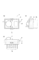
一層効率的な放熱を可能とすべく、ヒートシンクを併用することが好ましい。例えば、アルミ、セラミックス、銅、伝熱性の高い樹脂をヒートシンクとして用いることができる。ヒートシンクの形状は特に限定されない。例えば、図1(b)に示すように放熱用のフィン6aを多数設けることにより放熱領域の表面積を広くした形状であることが好ましい。なお、ヒートシンクと放熱性基板とを一体的に構成してもよい。
Hereafter, the component of the LED lighting apparatus in this invention is demonstrated in detail.
(Heat dissipation board)
The heat of the circuit element disposed thereon is efficiently released to the outside by the heat dissipating substrate. The material of the heat dissipating substrate is preferably excellent in thermal conductivity. For example, the heat dissipation substrate is formed of aluminum, ceramics, copper, or iron. The shape of the heat dissipation substrate is not particularly limited.
In order to enable more efficient heat dissipation, it is preferable to use a heat sink together. For example, aluminum, ceramics, copper, or a resin having high heat conductivity can be used as the heat sink. The shape of the heat sink is not particularly limited. For example, as shown in FIG. 1 (b), it is preferable to have a shape in which the surface area of the heat radiation area is increased by providing a large number of
(LED)
本発明では光源としてLEDを使用する。LEDの種類は特に限定されないが、例えば、封止樹脂にレンズを有する砲弾タイプやSMDタイプ(表面実装型)の素子を用いる。LEDの発光色も特に限定されず、例えば、白色LEDを使用することができる。
現在、一般的に使用されるLED(例えば白色LED)の動作電圧は約3V〜4Vである。LEDの電源として12ボルトの車両用バッテリーを使用する場合にはLEDの駆動電圧として約10V〜16Vを確保できる。以上のことを考慮すれば、LED照明装置に接続されるLEDの個数は1〜3個が好ましい。さらに好ましくは2個である。
(LED)
In the present invention, an LED is used as the light source. The type of LED is not particularly limited. For example, a bullet type or SMD type (surface mount type) element having a lens in a sealing resin is used. The emission color of the LED is not particularly limited, and for example, a white LED can be used.
Currently, the operating voltage of commonly used LEDs (for example, white LEDs) is about 3V to 4V. When a 12-volt vehicle battery is used as the power source of the LED, about 10V to 16V can be secured as the LED drive voltage. Considering the above, the number of LEDs connected to the LED lighting device is preferably 1 to 3. More preferably, it is two.
(定電流回路)
定電流回路はLEDに流れる電流を一定に制御するために用いられる。定電流回路の回路構成、定電流回路で使用される素子等は限定されない。車内などの限られたスペースにLED照明装置を設置する場合、定電流回路のサイズを小さくせざるを得ず、定電流回路を構成する素子を比較的狭い領域に配置することが要求される。このことから、定電流回路を構成する素子の数をできる限り少なくすることが好ましい。素子数を少なくすれば配置の自由度が高まり、発熱量の大きい素子をLEDから離して配置することが容易になるからである。また、素子数が少なければ定電流回路全体としての発熱量も低減し、LEDへの熱の影響が少なくなる。
(Constant current circuit)
The constant current circuit is used to control the current flowing through the LED to be constant. The circuit configuration of the constant current circuit, elements used in the constant current circuit, and the like are not limited. When the LED lighting device is installed in a limited space such as in a car, the size of the constant current circuit must be reduced, and the elements constituting the constant current circuit are required to be arranged in a relatively narrow region. For this reason, it is preferable to reduce the number of elements constituting the constant current circuit as much as possible. This is because if the number of elements is reduced, the degree of freedom in arrangement increases, and it becomes easy to arrange elements with a large amount of heat generation away from the LEDs. Also, if the number of elements is small, the amount of heat generated by the constant current circuit as a whole is also reduced, and the influence of heat on the LEDs is reduced.
例えば、定電流回路を構成する回路素子としてトランジスタ、抵抗、ツェナーダイオード、ダイオード等を使用する場合、発熱量はトランジスタが最も大きい。LEDと定電流回路を同一基板上に配置した場合、LEDとトランジスタとを可能な限り離れた位置に配置し、トランジスタの発熱の影響を受けにくくすることが好ましい。 For example, when a transistor, resistor, Zener diode, diode, or the like is used as a circuit element constituting the constant current circuit, the transistor generates the largest amount of heat. When the LED and the constant current circuit are arranged on the same substrate, it is preferable that the LED and the transistor are arranged as far as possible so as not to be affected by the heat generated by the transistor.
図2は本発明で用いる定電流回路の一例であり、図2(a)は、定電流回路をマイナス側で制御する場合の回路構成である。図2(b)は定電流回路をプラス側で制御する場合の回路構成である。 FIG. 2 shows an example of a constant current circuit used in the present invention, and FIG. 2A shows a circuit configuration when the constant current circuit is controlled on the minus side. FIG. 2B shows a circuit configuration when the constant current circuit is controlled on the plus side.
図1に本発明の実施例であるLED照明装置1を示す。LED照明装置1は車両室内で使用される。図1(a)はLED照明装置1の上面図であり、(b)及び(c)はそれぞれ(a)においてA側から観察した側面図及びB側から観察した側面図である。LED照明装置1では、放熱性基板5の上に定電流回路3並びにレンズ2が配置され、放熱性基板5の下にヒートシンク6が配置される。
FIG. 1 shows an
放熱性基板5は、定電流回路を構成する回路素子が発する熱を効率的に放出するために使用される。放熱性基板5は熱伝導性の優れたアルミやセラミックス等からなる。
ヒートシンク6は回路素子から放熱性基板に伝導された熱を効率的に放熱するために使用される。この例では、ヒートシンク6の材質は熱伝導性に優れたアルミやセラミックス等を使用し、その形状はフィン6aをいくつか設けて空気と接する面積を広くし放熱効果を高めている。
The
The
定電流回路は図2(a)に示す構成である。接続端子4を介して制御スイッチ及び車両用バッテリーと接続される。定電流回路10は、抵抗R1、抵抗R2、ツェナーダイオードZ1、PNP型トランジスタTr1、ダイオードD1から構成され、その定電流回路10に2個のLED1素子が接続される。なお、2個のLED1素子が1個のSMD型(表面実装型)LED32としてパッケージングされている。
レンズ2はLED32の発光を集光又は拡散するために用いられる。レンズ2の材質としてはポリカーボネート、アクリル樹脂、エポキシ樹脂等の合成樹脂やガラス等の無機材料が使用される。レンズ2は所定の照明領域にLED32素子の光を集光又は拡散するために適した形状を有する。
The constant current circuit has a configuration shown in FIG. The control switch and the vehicle battery are connected via the
The
図2(a)に示す定電流回路10ではバッテリー電圧に対して並列に抵抗R1とツェナーダイオードZ1が接続されている。ツェナーダイオードZ1はバッテリー電圧に対して逆方向電圧が印加されるように接続される。ツェナーダイオードZ1は降伏電圧以上の電圧値を印加することにより導通状態となる。抵抗R1の他端はトランジスタTr1のエミッタ側に接続される。一方、ツェナーダイオードZ1の他端はトランジスタTr1のベース側と抵抗R2とに接続される。トランジスタTr1のコレクタ側にはLED1素子が2個接続され、バッテリー電圧に対して順方向電圧が印加されるように接続される。さらに、抵抗R2とLED1素子とが接続され、その接続点とグランドとの間にダイオードD1がバッテリー電圧に対して順方向電圧が印加されるように接続される。
Resistor R 1 and the Zener diode Z 1 in parallel to the constant
このように構成される定電流回路においてバッテリー電圧がツェナーダイオードZ1の降伏電圧VZを超える場合は、ツェナーダイオードZ1が導通状態となる。すなわち、トランジスタTr1のエミッタ−ベース間に順方向電圧がかかり、トランジスタTr1がオン状態となり、エミッタ−コレクタ間に電流が流れる。このとき、LED1素子に流れる電流ILEDは次の式となる。
(数1)
ILED=(VZ−VBE)/R
ここで、VZはツェナーダイオードZ1の降伏電圧である。VBEはトランジスタTr1のベース−エミッタ間の電圧である。Rは、抵抗R1の抵抗値となる。
式1に示すようにツェナーダイオードZ1にかかる電圧が降伏電圧VZを超える電圧値を維持できれば、ツェナーダイオードZ1の端子間電圧は所定の降伏電圧VZに維持される。そのため、抵抗Rの抵抗値を調整することによりLED1素子に流れる電流ILEDを調整することができる。一方、降伏電圧よりも低い電圧がかかる場合はツェナーダイオードZ1が導通状態とはならず、トランジスタTr1はオフ状態となり、エミッタ−コレクタ間に電流が流れない。そのため、LED1素子へも電流ILEDが流れず、LED1素子の発光が生じない。すなわち、バッテリー電圧の変動範囲が、常にツェナーダイオードZ1の降伏電圧VZ以上であればLED1素子に対して一定の電流ILEDを供給することができる。
なお、抵抗R2を設けることにより所定の電流値以上のツェナー電流を流し、降伏電圧を安定化させる。また、ダイオードD1は、例えばモーター負荷がロックした場合のようなグランド側から車両用バッテリー側への異常電流の流入を阻止する。
If the battery voltage in this way comprised a constant current circuit exceeds the breakdown voltage V Z of the Zener diode Z 1 is composed a zener diode Z 1 is conductive. That is, the emitter of the transistor Tr 1 - takes forward voltage between the base, the transistor Tr 1 is turned on, the emitter - current flows between the collector. At this time, the current I LED flowing through one LED element is represented by the following equation.
(Equation 1)
I LED = (V Z -V BE ) / R
Here, V Z is the breakdown voltage of the Zener diode Z 1 . V BE is the base of the transistor Tr 1 - is the voltage between the emitter. R is a resistance value of the resistor R 1.
If the sustain voltage applied to the Zener diode Z 1 as shown in
By providing the resistor R 2 flowing a predetermined current value or more Zener current, it stabilizes the breakdown voltage. The diode D 1, for example a motor load is prevented from flowing from the ground side of the abnormal current to the vehicle battery side such as in the case of lock.
本実施例ではLED1素子を2個直列接続して使用する。これは、アノード−カソード間にかかる電圧に対し、LED1素子の動作電圧内で動作させるためである。例えば、供給電圧としてバッテリー電圧12Vを使用する場合、トランジスタTr1のコレクタとダイオードD1のアノード間にかかる電圧は約8Vである。これに対して、本実施例で使用するLED1素子の動作電圧は約3.5Vである。すなわち、LED1素子が1個であれば、トランジスタTr1にかかる電圧が大きく、LED1素子が3個であればLED1素子1個当りのかかる電圧が低く、十分な発光が得られない。LED1素子の接続個数が2個であればLED1素子1つ当りにかかる電圧が動作電圧となる。 Using the LED 1 element two series-connected to the present embodiment. This is because the voltage applied between the anode and the cathode is operated within the operating voltage of one LED element. For example, when using a battery voltage of 12V as the supply voltage, the voltage applied between the anode collector and the diode D 1 of the transistor Tr 1 is about 8V. On the other hand, the operating voltage of one LED element used in this embodiment is about 3.5V. That is, if LED 1 element is one, large voltage applied to the transistor Tr 1 is, LED 1 element 3 a long if LED 1 element per consuming voltage low, no sufficient light emission is obtained. The number of connected LED 1 element voltage applied to per LED 1 element one if two becomes the operating voltage.
以上のように構成される定電流回路により、LED1素子に流れる電流ILEDを一定値に保持することが可能となり、バッテリー電圧の変動による影響を受けることなく安定したLED1素子の発光を維持することが可能となる。 The constant current circuit configured as described above makes it possible to maintain the current I LED flowing through one LED element at a constant value, and maintain stable light emission of the one LED element without being affected by fluctuations in battery voltage. It becomes possible to do.
図3に定電流回路33とLED素子31との配置関係を示す。定電流回路33を構成する素子の数を少なくしたため、基板上における素子の配置に余裕を持たせることが可能となっている。図3に示すように定電流回路33を構成する素子の中で発熱量の大きいトランジスタ34とLED素子31とを基板の相対向する縁に沿って配置し、その離隔距離を最大とする。これによりトランジスタ34からLED素子31へ伝導する熱が効率的に放熱性基板及びヒートシンクから放熱される。よって、トランジスタ34の発熱からLED素子31を保護することができる。その結果、LED素子31の安定駆動及びその長寿命化が達成される。
なお、基板上におけるLED素子31とトランジスタ34との配置関係は図3に示すものに限定されず、2者間を基板の相対向する隅部に配置してもよい。
FIG. 3 shows an arrangement relationship between the constant
In addition, the arrangement | positioning relationship between the
以上のようにLED発光装置1ではLEDとバッテリーとの間に定電流回路を接続することによりバッテリー電圧が変動したとしてもLEDに流れる電流を安定化させることが可能となる。すなわち、バッテリー電圧の変動によるLED発光のちらつき防止や、LEDにかかる電圧の増加に起因するLEDの過剰発熱を回避できる。また、基板上でのLEDとトランジスタなどの発熱量の大きい素子とを離すことによりLED自体への熱伝導を回避することができる。よって、LEDの安定的な駆動及びLEDの長寿命化を達成できる。
As described above, in the LED light-emitting
この発明は上記発明の実施の態様及び実施例の説明に何ら限定されるものではない。特許請求の範囲を逸脱せず、当業者が容易に想到できる範囲で種々の変形態様もこの発明に含まれる。 The present invention is not limited to the description of the embodiments and examples of the invention described above. Various modifications are also included in the present invention as long as those skilled in the art can easily conceive without departing from the scope of the claims.
1 30 LED照明装置
3 10 20 33 定電流回路
5 放熱性基板
6 ヒートシンク
31 LED素子
1 30
Claims (4)
前記放熱性基板上に配置される少なくとも1個のLEDと、
前記LEDに接続されている定電流回路と、
を備えるLED照明装置。 A heat dissipation substrate;
At least one LED disposed on the heat dissipation substrate;
A constant current circuit connected to the LED;
LED lighting device comprising:
供給電圧に対して逆方向に接続されるツェナーダイオードと、
前記LEDへ流れる電流を制御するためのトランジスタと、
前記トランジスタのエミッタ電流を制御するための第1の抵抗と、
前記ツェナーダイオードに流れる電流を制御するための第2の抵抗と、
供給電圧に対して順方向に接続されるダイオードと、
を含み、
前記トランジスタのコレクタが前記LEDに接続され、前記トランジスタのエミッタが前記第1の抵抗に接続され、前記トランジスタのベースがツェナーダイオードに接続されると共に前記第2の抵抗に接続され、前記第1の抵抗と前記ツェナーダイオードとが接続され、前記第2の抵抗と前記LEDとが接続される、
ことを特徴とする請求項1又は2に記載のLED照明装置。 The constant current circuit is
A Zener diode connected in the opposite direction to the supply voltage;
A transistor for controlling the current flowing to the LED;
A first resistor for controlling the emitter current of the transistor;
A second resistor for controlling the current flowing through the Zener diode;
A diode connected in the forward direction to the supply voltage;
Including
The collector of the transistor is connected to the LED, the emitter of the transistor is connected to the first resistor, the base of the transistor is connected to a Zener diode and to the second resistor, and the first resistor A resistor and the Zener diode are connected, and the second resistor and the LED are connected.
The LED illumination device according to claim 1 or 2, wherein
Priority Applications (2)
| Application Number | Priority Date | Filing Date | Title |
|---|---|---|---|
| JP2004285806A JP2006100633A (en) | 2004-09-30 | 2004-09-30 | Led lighting device |
| US11/237,910 US7462994B2 (en) | 2004-09-30 | 2005-09-29 | LED illumination apparatus |
Applications Claiming Priority (1)
| Application Number | Priority Date | Filing Date | Title |
|---|---|---|---|
| JP2004285806A JP2006100633A (en) | 2004-09-30 | 2004-09-30 | Led lighting device |
Publications (2)
| Publication Number | Publication Date |
|---|---|
| JP2006100633A true JP2006100633A (en) | 2006-04-13 |
| JP2006100633A5 JP2006100633A5 (en) | 2007-02-15 |
Family
ID=36144586
Family Applications (1)
| Application Number | Title | Priority Date | Filing Date |
|---|---|---|---|
| JP2004285806A Withdrawn JP2006100633A (en) | 2004-09-30 | 2004-09-30 | Led lighting device |
Country Status (2)
| Country | Link |
|---|---|
| US (1) | US7462994B2 (en) |
| JP (1) | JP2006100633A (en) |
Cited By (4)
| Publication number | Priority date | Publication date | Assignee | Title |
|---|---|---|---|---|
| JP2009277705A (en) * | 2008-05-12 | 2009-11-26 | Koa Corp | Package light-emitting component and method of manufacturing the same |
| JP2010226119A (en) * | 2007-01-11 | 2010-10-07 | Yiguang Electronic Ind Co Ltd | Alternating current system light emitting diode device |
| KR101275392B1 (en) * | 2012-01-25 | 2013-06-17 | 조기상 | Circuit of led light for car and fixing apparatus |
| JP2015511066A (en) * | 2012-03-06 | 2015-04-13 | コーニンクレッカ フィリップス エヌ ヴェ | Lighting module and method for manufacturing the lighting module |
Families Citing this family (8)
| Publication number | Priority date | Publication date | Assignee | Title |
|---|---|---|---|---|
| WO2008096249A2 (en) * | 2007-02-07 | 2008-08-14 | Melexis Nv | Led driver |
| US8405318B2 (en) * | 2007-02-28 | 2013-03-26 | Koa Corporation | Light-emitting component and its manufacturing method |
| US20100046226A1 (en) * | 2008-06-18 | 2010-02-25 | Cooper Technologies Company | Light Fixture With An Adjustable Optical Distribution |
| TW201038132A (en) * | 2009-04-10 | 2010-10-16 | Advanced Connectek Inc | AC LED having current regulative diode |
| FR2963532B1 (en) * | 2010-07-30 | 2013-06-14 | Valeo Vision | INTENSITY MONITORING SYSTEM AT LEAST ONE LIGHT EMITTING DIODE |
| GB2492551A (en) * | 2011-07-04 | 2013-01-09 | Accuric Ltd | Current regulator |
| WO2013080689A1 (en) * | 2011-11-28 | 2013-06-06 | コニカミノルタ株式会社 | Illumination device and light-emission module |
| KR102599507B1 (en) * | 2018-09-17 | 2023-11-09 | 삼성디스플레이 주식회사 | Display device |
Citations (7)
| Publication number | Priority date | Publication date | Assignee | Title |
|---|---|---|---|---|
| JPS588967U (en) * | 1981-07-10 | 1983-01-20 | 日本電気株式会社 | light emitting diode |
| JPH10303467A (en) * | 1997-04-28 | 1998-11-13 | Rohm Co Ltd | Multichip module |
| US5933441A (en) * | 1997-11-06 | 1999-08-03 | Chen; Hung-Ping | Circuit for protecting a laser indicator |
| JP2003069083A (en) * | 2001-08-28 | 2003-03-07 | Matsushita Electric Works Ltd | Light emitting device |
| US6600274B1 (en) * | 2001-12-14 | 2003-07-29 | Dme Corporation | LED current regulation circuit for aircraft lighting system |
| JP2003258314A (en) * | 2001-12-26 | 2003-09-12 | Toyoda Gosei Co Ltd | Led lamp unit |
| WO2004023522A2 (en) * | 2002-09-04 | 2004-03-18 | Cree, Inc. | Power surface mount light emitting die package |
Family Cites Families (7)
| Publication number | Priority date | Publication date | Assignee | Title |
|---|---|---|---|---|
| US5420768A (en) * | 1993-09-13 | 1995-05-30 | Kennedy; John | Portable led photocuring device |
| JP3245329B2 (en) * | 1995-06-19 | 2002-01-15 | 京セラ株式会社 | Package for storing semiconductor elements |
| US6550953B1 (en) * | 1999-08-20 | 2003-04-22 | Toyoda Gosei Co. Ltd. | Light emitting diode lamp device |
| US6636003B2 (en) * | 2000-09-06 | 2003-10-21 | Spectrum Kinetics | Apparatus and method for adjusting the color temperature of white semiconduct or light emitters |
| WO2003020737A1 (en) * | 2001-09-05 | 2003-03-13 | Bristol-Myers Squibb Company | O-pyrazole glucoside sglt2 inhibitors and method of use |
| TW577178B (en) * | 2002-03-04 | 2004-02-21 | United Epitaxy Co Ltd | High efficient reflective metal layer of light emitting diode |
| JP2004253364A (en) * | 2003-01-27 | 2004-09-09 | Matsushita Electric Ind Co Ltd | Lighting system |
-
2004
- 2004-09-30 JP JP2004285806A patent/JP2006100633A/en not_active Withdrawn
-
2005
- 2005-09-29 US US11/237,910 patent/US7462994B2/en active Active
Patent Citations (7)
| Publication number | Priority date | Publication date | Assignee | Title |
|---|---|---|---|---|
| JPS588967U (en) * | 1981-07-10 | 1983-01-20 | 日本電気株式会社 | light emitting diode |
| JPH10303467A (en) * | 1997-04-28 | 1998-11-13 | Rohm Co Ltd | Multichip module |
| US5933441A (en) * | 1997-11-06 | 1999-08-03 | Chen; Hung-Ping | Circuit for protecting a laser indicator |
| JP2003069083A (en) * | 2001-08-28 | 2003-03-07 | Matsushita Electric Works Ltd | Light emitting device |
| US6600274B1 (en) * | 2001-12-14 | 2003-07-29 | Dme Corporation | LED current regulation circuit for aircraft lighting system |
| JP2003258314A (en) * | 2001-12-26 | 2003-09-12 | Toyoda Gosei Co Ltd | Led lamp unit |
| WO2004023522A2 (en) * | 2002-09-04 | 2004-03-18 | Cree, Inc. | Power surface mount light emitting die package |
Cited By (4)
| Publication number | Priority date | Publication date | Assignee | Title |
|---|---|---|---|---|
| JP2010226119A (en) * | 2007-01-11 | 2010-10-07 | Yiguang Electronic Ind Co Ltd | Alternating current system light emitting diode device |
| JP2009277705A (en) * | 2008-05-12 | 2009-11-26 | Koa Corp | Package light-emitting component and method of manufacturing the same |
| KR101275392B1 (en) * | 2012-01-25 | 2013-06-17 | 조기상 | Circuit of led light for car and fixing apparatus |
| JP2015511066A (en) * | 2012-03-06 | 2015-04-13 | コーニンクレッカ フィリップス エヌ ヴェ | Lighting module and method for manufacturing the lighting module |
Also Published As
| Publication number | Publication date |
|---|---|
| US20060076905A1 (en) | 2006-04-13 |
| US7462994B2 (en) | 2008-12-09 |
Similar Documents
| Publication | Publication Date | Title |
|---|---|---|
| US7462994B2 (en) | LED illumination apparatus | |
| US8262256B2 (en) | Semiconductor light module | |
| US7401945B2 (en) | Light source arrangement | |
| US8299693B2 (en) | Lamp device of high heat dissipation efficiency | |
| JP4970232B2 (en) | Vehicle lighting | |
| EP2287527A1 (en) | Light emitting diode lighting device | |
| JP6720753B2 (en) | Vehicle lighting device and vehicle lamp | |
| JP2010015887A (en) | Led lighting control circuit and vehicle lamp fixture equipped with this | |
| US9493110B2 (en) | Vehicular headlamp | |
| US9345075B2 (en) | Vehicular headlamp | |
| JP2012104689A (en) | Light-emitting module and vehicle lamp | |
| US9820354B2 (en) | Light emitting device and automotive lighting including the same | |
| JP2009206422A (en) | Surface mounting led package | |
| JP6922578B2 (en) | Vehicle lighting and vehicle lighting | |
| JP7319591B2 (en) | Vehicle lighting device and vehicle lamp | |
| EP3734138B1 (en) | Lighting apparatus | |
| JP2013203373A (en) | Indoor lighting device for vehicle | |
| JP6252931B2 (en) | Lighting device and lighting apparatus using the same | |
| JP2009272146A (en) | Vehicular room light | |
| KR20170037382A (en) | Fishing lamp containing stabilizer with moisture elimination | |
| JP2015214173A (en) | Lighting circuit for vehicular lighting fixture, light source unit for vehicular lighting fixture and vehicular lighting fixture | |
| US11920753B2 (en) | LED module with thermal insulation towards optical component and vehicle headlight with such LED module | |
| JP7212823B2 (en) | Light source module and vehicle lamp | |
| JP7069522B2 (en) | Vehicle lighting equipment and vehicle lighting equipment | |
| JP2022129519A (en) | Vehicular illuminating device, and vehicular lamp fitting |
Legal Events
| Date | Code | Title | Description |
|---|---|---|---|
| A521 | Written amendment |
Free format text: JAPANESE INTERMEDIATE CODE: A523 Effective date: 20061226 |
|
| A621 | Written request for application examination |
Free format text: JAPANESE INTERMEDIATE CODE: A621 Effective date: 20070125 |
|
| A977 | Report on retrieval |
Free format text: JAPANESE INTERMEDIATE CODE: A971007 Effective date: 20090611 |
|
| A131 | Notification of reasons for refusal |
Free format text: JAPANESE INTERMEDIATE CODE: A131 Effective date: 20090623 |
|
| A521 | Written amendment |
Free format text: JAPANESE INTERMEDIATE CODE: A523 Effective date: 20090818 |
|
| A131 | Notification of reasons for refusal |
Free format text: JAPANESE INTERMEDIATE CODE: A131 Effective date: 20091020 |
|
| A761 | Written withdrawal of application |
Free format text: JAPANESE INTERMEDIATE CODE: A761 Effective date: 20091203 |