JP2006094013A - PoE SYSTEM - Google Patents
PoE SYSTEM Download PDFInfo
- Publication number
- JP2006094013A JP2006094013A JP2004275704A JP2004275704A JP2006094013A JP 2006094013 A JP2006094013 A JP 2006094013A JP 2004275704 A JP2004275704 A JP 2004275704A JP 2004275704 A JP2004275704 A JP 2004275704A JP 2006094013 A JP2006094013 A JP 2006094013A
- Authority
- JP
- Japan
- Prior art keywords
- input terminal
- output terminal
- power supply
- signal
- power
- Prior art date
- Legal status (The legal status is an assumption and is not a legal conclusion. Google has not performed a legal analysis and makes no representation as to the accuracy of the status listed.)
- Pending
Links
Images


Abstract
Description
本発明は、イーサネット(登録商標)ネットワークにおいて、イーサネットケーブルの空き線を利用して直流電力を供給するPoE(Power over Ethernet)システムに関するものである。 The present invention relates to a PoE (Power over Ethernet) system that supplies DC power using an unused line of an Ethernet cable in an Ethernet (registered trademark) network.
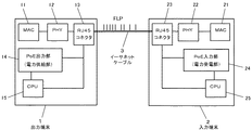
PoEシステムは、イーサネットケーブルの通信に使っていないペア線を利用して直流電力を端末に供給するものであり、図7に示すように、情報を入出力するとともに電力を供給する出力端末1と、情報を入出力するとともに電力を受電される入力端末2をイーサネットケーブル3で接続して構成される。出力端末1はもちろん、入力端末2も従来のイーサネット端末(PoE未対応)にはない、検知用回路等の特殊な電気回路が必要である。
The PoE system supplies a pair of DC power to a terminal using a pair wire that is not used for Ethernet cable communication. As shown in FIG. 7, an
出力端末1と入力端末2を接続してからのシーケンスは、図8のようになる。ここで、接続検出では、接続された端末が入力端末(給電可能=PoE対応)であるかの検出処理を行う。クラス分けでは、あらかじめ規定された5段階(クラス)の供給電力の上限値があり、接続された入力端末のクラスの検知処理を行う。このクラス分けはオプションであり、実装しなくてもよい。電力供給では、接続検出およびクラス分けが終了した後、入力端末に向けて電力供給を開始する。メンテナンスモードでは、端末の接続が継続しているかの検知を行う。接続の終了つまり非接続が検出された場合は、電力供給を中断し、アイドル状態に戻る。接続が継続していることが検知された場合は、引き続き電力供給を継続する。
The sequence after connecting the
なお、特許文献1にはイーサネットケーブルを用いた給電装置が開示されており、情報を入出力するとともに電力を供給する出力端末と、情報を入出力するとともに電力を受電される入力端末とをイーサネットケーブルによって接続してなる構成が開示されている。
従来のPoEシステムにおいては、入力端末検知やメンテナンスモードで端末接続状態の確認の処理をするために、出力端末から入力端末の当該回路に一方的にアナログ信号を送出する。入力端末の当該回路は受動部品で構成されており、固有の抵抗値や時定数を持つ。出力端末から送出されたアナログ信号は、この回路を通ることで波形が変形し、入力端末から出力端末に戻る。出力端末では、戻ってきた信号をサンプリングし、その電圧・電流値を基に処理を行う。これらの入力端末の当該回路は受動的なもので、自身の情報を積極的に通知するものではない。 In the conventional PoE system, an analog signal is unilaterally sent from the output terminal to the relevant circuit of the input terminal in order to perform processing for checking the terminal connection state in the input terminal detection and maintenance mode. The circuit of the input terminal is composed of passive components and has a specific resistance value and time constant. The analog signal sent from the output terminal passes through this circuit and its waveform is deformed, and returns from the input terminal to the output terminal. The output terminal samples the returned signal and performs processing based on the voltage / current value. The circuits of these input terminals are passive and do not actively notify their information.
従来のPoEシステムにおいては、アナログ処理のため、検知処理や端末接続状態確認の処理において誤検知が発生しやすい。例えば、従来のイーサネット端末(PoE未対応)を接続した場合、端末の回路構成によっては、入力端末であると誤検知して直流電力を供給し、端末の回路を破損する場合がある。また、端末接続状態の確認において、接続が終了したにもかかわらず、接続が継続されていると誤検知して直流電力の供給を継続する場合がある。 In the conventional PoE system, because of analog processing, erroneous detection is likely to occur in detection processing and terminal connection state confirmation processing. For example, when a conventional Ethernet terminal (PoE incompatible) is connected, depending on the terminal circuit configuration, it may be erroneously detected as an input terminal and DC power may be supplied, damaging the terminal circuit. Further, in the confirmation of the terminal connection state, there is a case where the connection of DC power is continued by erroneously detecting that the connection is continued despite the termination of the connection.
本発明は、このような点に鑑みてなされたものであり、PoEの接続検知にネゴシエーションを用いることにより誤検知を無くし、信頼性を向上させたPoEシステムを提供することを課題とする。 This invention is made in view of such a point, and makes it a subject to provide the PoE system which eliminated the misdetection and improved the reliability by using the negotiation for the PoE connection detection.
本発明のPoEシステムによれば、上記の課題を解決するために、図1に示すように、情報を入出力するとともに電力を供給する出力端末1と、情報を入出力するとともに電力を受電される入力端末2とをイーサネットケーブル3によって接続してなるPoEシステムにおいて、出力端末1から特定の応答要求信号を送信した後に入力端末2からの応答信号があることを確認するネゴシエーションによって、入力端末2が受電可能であることを確認してから電力供給を開始することを特徴とするものである。また、電力供給開始後は、図2に示すように、一定時間毎に出力端末1から応答要求信号を送信し、入力端末2からの応答信号により検出された入力端末2の受電状態に応じて出力端末1からの電力の供給状態を制御することを特徴とするものである。また、電力供給開始後の応答要求信号に対して、入力端末2からの応答信号が無くなると出力端末1からの電力供給を中断させることを特徴とするものである。
According to the PoE system of the present invention, in order to solve the above problems, as shown in FIG. 1, an
請求項1の発明によれば、出力端末と入力端末間でネゴシエーションを行うことにより、接続された端末が受電可能な端末であるかの検出が正確に行われるため、受電できない端末に電力を供給するおそれがなくなる。
請求項2の発明によれば、電力供給開始後においても、入力端末が接続中であるかの検出が正確に行われるため、接続が終了したにもかかわらず電力供給が継続するおそれがなくなる。また、電力供給開始後においても、給電状態を確認できるために、常に適正な給電状態を維持できる。
請求項3の発明によれば、入力端末が一時的に応答信号の送出ができなくなった場合においても、出力端末から応答要求信号を再送することにより、入力端末とのネゴシエーションができ、信頼性の向上を図ることができる。
According to the first aspect of the present invention, by performing negotiation between the output terminal and the input terminal, it is possible to accurately detect whether the connected terminal is a terminal that can receive power. The risk of doing so is eliminated.
According to the invention of
According to the invention of
請求項4の発明によれば、パルス間隔情報を用いることにより、簡易なハードウェア構成でネゴシエーションを実現できる。
請求項5の発明によれば、ネゴシエーション用の信号にイーサネット信号のFLPを用いることにより、応答要求信号が追加されても全体としての通信効率は下がらない。また、簡易なハードウェア構成でネゴシエーションを実現できる。
According to the invention of
According to the invention of claim 5, by using the Ethernet signal FLP as the negotiation signal, the communication efficiency as a whole is not lowered even if a response request signal is added. In addition, negotiation can be realized with a simple hardware configuration.
(実施形態1)
図1は本発明の実施形態1に係るPoEシステムの構成を示すブロック図である。このPoEシステムは、情報を入出力するとともに電力を供給する出力端末1と、情報を入出力するとともに電力を受電される入力端末2を、イーサネットケーブル3で接続して構成される。図中、MACはイーサネット情報信号の処理部、PHYはイーサネット情報信号の信号変換部、RJ45コネクタはイーサネットケーブル3を接続するコネクタであり、これらは情報入出力部を構成している。
(Embodiment 1)
FIG. 1 is a block diagram showing a configuration of a PoE system according to
出力端末1は、上述の情報入出力部(MAC11、PHY12、RJ45コネクタ13)のほかに、電力供給部であるPoE出力部14、電力供給の制御部であるCPU15、ネゴシエーションに用いるRS−232Cドライバ16を備えている。入力端末2は、情報入出力部(MAC21、PHY22、RJ45コネクタ23)のほかに、電力受電部であるPoE入力部24、電力受電の制御部であるCPU25、ネゴシエーションに用いるRS−232Cドライバ26を備えている。
In addition to the information input / output unit (MAC11, PHY12, RJ45 connector 13) described above, the
本実施形態のPoEシステムでは、接続時に出力端末1と入力端末2間でネゴシエーションを行う。出力端末1から、接続された入力端末2は受電可能であるかということを問い合わせる特定の信号(応答要求信号)を送出する。入力端末2では、出力端末1からの応答要求信号を受信すると、自己は受電可能であるとの応答信号を送出する。応答信号を受けた出力端末1はクラス分け(オプション)を行った後、給電を開始する。
In the PoE system of this embodiment, negotiation is performed between the
本実施形態において、接続検出のネゴシエーションはRS−232Cプロトコルにて行われる。出力端末1側では、CPU15からRS−232Cドライバ16を通してRS−232Cプロトコルに基づいた応答要求信号を送信し、接続された端末が入力端末(PoE対応)であるか問い合わせる。入力端末2側では、RS−232Cドライバ26を通してRS−232Cプロトコルに基づいた応答要求信号がCPU25に入力される。応答要求信号による問い合わせを受けたCPU25は、自身はPoE対応であるとの応答信号を送信する。この応答信号もまた、RS−232Cドライバ26を通してRS−232Cプロトコルに基づいて送信される。入力端末2からの応答信号を受けた出力端末1のCPU15は、クラス分け(オプション)を行った後、PoE出力部14に対し、電力供給を開始するよう命令を出し、PoE出力部14から電力が供給される。
In the present embodiment, the connection detection negotiation is performed using the RS-232C protocol. On the
(実施形態2)
図2は本発明の実施形態2に係るPoEシステムの動作を示すフローチャートである。システムの構成及び接続検出・給電開始までの動作は実施形態1と同様である。本実施形態2のPoEシステムでは、給電開始後にも一定時間毎にネゴシエーションを行うことによって、端末接続状態の検出を行う。出力端末1から、入力端末2は接続中であるかということを問い合わせる特定の信号(応答要求信号)を送信する。入力端末2側では、出力端末1からの応答要求信号を受けて、自身は接続中であるとの情報および給電電圧・給電電力の情報を含む応答信号を送信する。応答信号を受けた出力端末1のCPU15は、給電電圧・給電電力の情報を基に適正な値に修正制御された給電を継続する。応答信号を受信できない場合は、出力端末1は入力端末2が接続されていないと判断し、給電を中断する。
(Embodiment 2)
FIG. 2 is a flowchart showing the operation of the PoE system according to the second embodiment of the present invention. The system configuration and the operations up to connection detection / power supply start are the same as in the first embodiment. In the PoE system according to the second embodiment, the terminal connection state is detected by performing negotiation at regular intervals even after the start of power supply. The
給電開始後の動作を図2のフローチャートにより説明する。図中の左側のフローは出力端末1側のCPU15の動作を示しており、右側のフローは入力端末2側のCPU25の動作を示している。給電開始後に、CPU15のタイマー機能などを用いて、一定時間毎に入力端末2が接続中かを問い合わせる応答要求信号を送信する。この応答要求信号は、CPU15からRS−232Cドライバ16を通してRS−232Cプロトコルに基づいて送信される。その後、CPU15はRS−232Cドライバ16を受信状態とし、入力端末2側から応答信号が返信されてくるのを待つ。入力端末2側から出力端末1に対して、自身は接続中であることを知らせる応答信号が返信されれば、応答信号に含まれている給電電圧・給電電力の情報を基に、PoE出力部14に対して制御を行い、適正な値に修正された給電電圧・給電電力の供給を継続する。所定時間内に応答信号を受信できない場合は、出力端末1は入力端末2が接続されていないと判断し、PoE出力部14に対して給電を中断するよう命令を出し、給電は中断される。
The operation after the start of power feeding will be described with reference to the flowchart of FIG. The left flow in the figure shows the operation of the
入力端末2側では、CPU25によりRS−232Cドライバ26を常時は受信状態としておいて、応答要求信号を受信すると、RS−232Cドライバ26を送信状態に切り替えて、自身は接続中であるとの情報と給電電圧・給電電力の情報を含む応答信号を送信する。その後、CPU25は再びRS−232Cドライバ26を受信状態とし、次の応答要求信号が受信されるまで待機する。
On the
(実施形態3)
本発明の実施形態3を図3により説明する。図3に示すように、一過性の外来ノイズ等により、入力端末2が応答信号を送信できない場合がある。例えば、応答要求信号が到来したタイミングにイーサネットケーブル3またはRS−232Cドライバ26に外来ノイズが混入した場合には、CPU25が応答要求信号を認識できないので、応答信号を返信できない。そこで、出力端末1のCPU15では、接続時に応答要求信号を送信した後、入力端末2からの応答信号が返信されない場合であっても、即時にPoE未対応端末とは判断せずに、問い合わせの応答要求信号を再送する。出力端末1からの応答要求信号の送信回数があらかじめ設定した回数に達しても入力端末2からの応答が無い場合は、入力端末2は接続されていないものと判断し、電力の供給は行わない。
(Embodiment 3)
A third embodiment of the present invention will be described with reference to FIG. As shown in FIG. 3, the
また、給電開始後にも一定時間毎に、端末接続状態の検出を行うべく、出力端末1から入力端末2に対して応答要求信号を送信する。入力端末2側では、出力端末1からの応答要求信号を受けて、自身は接続中であるとの情報および給電電圧・給電電力の情報を含む応答信号を送信する。応答信号を受けた出力端末1のCPU15は、給電電圧・給電電力の情報を基に適正な値に修正制御された給電を継続する。応答信号を受信できない場合は、応答要求信号を再送する。出力端末1からの応答要求信号の送信回数があらかじめ設定した回数に達しても入力端末2からの応答が無い場合は、入力端末2は接続されていないものと判断し、給電を中断する。その他の構成及び動作については実施形態1,2と同様である。
Further, a response request signal is transmitted from the
(実施形態4)
本発明の実施形態4を図4により説明する。上述の実施形態1〜3では、ネゴシエーションにRS−232Cドライバ16,26を用いているが、この実施形態4では、ネゴシエーションの応答要求信号と応答信号の送受信にパルス間隔情報を用いる。これは、イーサネットケーブル3上を伝送される信号パルスの間隔を利用して応答要求信号と応答信号の情報を伝達するものである。
(Embodiment 4)
A fourth embodiment of the present invention will be described with reference to FIG. In the first to third embodiments described above, the RS-
出力端末1と入力端末2は共に、自己が送信する情報に応じて信号パルス列のパルス間隔を変化させる。また、信号パルス列を受け取った側では、パルス間隔を読み取り、情報を認識する。その他の構成及び動作については、実施形態1〜3と同様である。
Both the
(実施形態5)
本発明の実施形態5を図5及び図6により説明する。上述の実施形態1,2では、ネゴシエーションにRS−232Cドライバ16,26を用いているが、この実施形態5では、イーサネット信号のFLP(Fast Link Pulse)の拡張用リザーブドビットを利用することで、ネゴシエーションを行うことを特徴とする。例えば、出力端末1は、図6に示すFLPの拡張用リザーブドビットのA5ビットに情報を入れ、入力端末2はA6ビットに情報を入れる。その他の構成及び動作については、実施形態1〜3と同様である。
(Embodiment 5)
A fifth embodiment of the present invention will be described with reference to FIGS. In the first and second embodiments described above, the RS-
1 出力端末
2 入力端末
3 イーサネットケーブル
14 PoE出力部(電力供給部)
24 PoE入力部(電力受電部)
1
24 PoE input unit (power receiving unit)
Claims (5)
Priority Applications (1)
| Application Number | Priority Date | Filing Date | Title |
|---|---|---|---|
| JP2004275704A JP2006094013A (en) | 2004-09-22 | 2004-09-22 | PoE SYSTEM |
Applications Claiming Priority (1)
| Application Number | Priority Date | Filing Date | Title |
|---|---|---|---|
| JP2004275704A JP2006094013A (en) | 2004-09-22 | 2004-09-22 | PoE SYSTEM |
Publications (1)
| Publication Number | Publication Date |
|---|---|
| JP2006094013A true JP2006094013A (en) | 2006-04-06 |
Family
ID=36234573
Family Applications (1)
| Application Number | Title | Priority Date | Filing Date |
|---|---|---|---|
| JP2004275704A Pending JP2006094013A (en) | 2004-09-22 | 2004-09-22 | PoE SYSTEM |
Country Status (1)
| Country | Link |
|---|---|
| JP (1) | JP2006094013A (en) |
Cited By (9)
| Publication number | Priority date | Publication date | Assignee | Title |
|---|---|---|---|---|
| JP2008515258A (en) * | 2004-09-24 | 2008-05-08 | シーメンス アクチエンゲゼルシヤフト | COMMUNICATION SYSTEM, DISTRIBUTION ELEMENT, AND NETWORK DEVICE |
| JP2008123051A (en) * | 2006-11-08 | 2008-05-29 | Sony Corp | Power supply system, power supply method, and power supply program |
| JP2008294951A (en) * | 2007-05-28 | 2008-12-04 | Nec Access Technica Ltd | Power receiving device and power feeding device |
| JP2009535985A (en) * | 2006-04-29 | 2009-10-01 | エイ・ティ・アンド・ティ・コーポレーション | Device for synchronizing access points in a WLAN using direct spread spectrum signaling |
| JP2010079450A (en) * | 2008-09-24 | 2010-04-08 | Toyo Electric Corp | Space optical transmission device |
| JP2011100491A (en) * | 2011-02-07 | 2011-05-19 | Sony Corp | Apparatus and method for processing information and computer program |
| JP2014531728A (en) * | 2011-10-06 | 2014-11-27 | コーニンクレッカ フィリップス エヌ ヴェ | Electric lighting system power control |
| US9049028B2 (en) | 2007-10-31 | 2015-06-02 | Sony Corporation | Power supplying system, monitoring apparatus, monitoring method and computer program |
| JP2017532931A (en) * | 2014-08-08 | 2017-11-02 | フィリップス ライティング ホールディング ビー ヴィ | Power transfer through powered device |
-
2004
- 2004-09-22 JP JP2004275704A patent/JP2006094013A/en active Pending
Cited By (16)
| Publication number | Priority date | Publication date | Assignee | Title |
|---|---|---|---|---|
| US7898107B2 (en) | 2004-09-24 | 2011-03-01 | Siemens Aktiengesellschaft | Communication system, distribution element and network device |
| JP2008515258A (en) * | 2004-09-24 | 2008-05-08 | シーメンス アクチエンゲゼルシヤフト | COMMUNICATION SYSTEM, DISTRIBUTION ELEMENT, AND NETWORK DEVICE |
| US10050768B2 (en) | 2006-04-29 | 2018-08-14 | At&T Intellectual Property Ii, L.P. | Arrangement for synchronizing access points in WLAN using direct-sequence spread spectrum signaling |
| JP2009535985A (en) * | 2006-04-29 | 2009-10-01 | エイ・ティ・アンド・ティ・コーポレーション | Device for synchronizing access points in a WLAN using direct spread spectrum signaling |
| US9408169B2 (en) | 2006-04-29 | 2016-08-02 | At&T Intellectual Property I, L.P. | Arrangement for synchronizing access points in WLAN using direct-sequence spread spectrum signaling |
| JP2008123051A (en) * | 2006-11-08 | 2008-05-29 | Sony Corp | Power supply system, power supply method, and power supply program |
| JP2008294951A (en) * | 2007-05-28 | 2008-12-04 | Nec Access Technica Ltd | Power receiving device and power feeding device |
| JP4687916B2 (en) * | 2007-05-28 | 2011-05-25 | Necアクセステクニカ株式会社 | Power supply / reception system |
| US9049028B2 (en) | 2007-10-31 | 2015-06-02 | Sony Corporation | Power supplying system, monitoring apparatus, monitoring method and computer program |
| JP2010079450A (en) * | 2008-09-24 | 2010-04-08 | Toyo Electric Corp | Space optical transmission device |
| JP2011100491A (en) * | 2011-02-07 | 2011-05-19 | Sony Corp | Apparatus and method for processing information and computer program |
| JP2014531728A (en) * | 2011-10-06 | 2014-11-27 | コーニンクレッカ フィリップス エヌ ヴェ | Electric lighting system power control |
| US10034340B2 (en) | 2011-10-06 | 2018-07-24 | Philips Lighting Holding B.V. | Electrical lighting system power control |
| JP2017532931A (en) * | 2014-08-08 | 2017-11-02 | フィリップス ライティング ホールディング ビー ヴィ | Power transfer through powered device |
| US10122545B2 (en) | 2014-08-08 | 2018-11-06 | Philips Lighting Holding B.V. | Power forwarding via a powered device |
| RU2691218C2 (en) * | 2014-08-08 | 2019-06-11 | Филипс Лайтинг Холдинг Б.В. | Power transfer through a powered device |
Similar Documents
| Publication | Publication Date | Title |
|---|---|---|
| JP6974686B2 (en) | Power saving mode for USB power transfer sourcing devices | |
| US9690732B2 (en) | Power-over-ethernet (POE)-enabled network device and USB device power negotiation using USB to POE protocol conversion | |
| US8694710B2 (en) | Conversion of a two-wire bus into a single-wire bus | |
| JP5992565B2 (en) | Edge-based communication | |
| JP4936204B2 (en) | Communication system and communication method | |
| CN105183687B (en) | A kind of timesharing serial port communication method and system | |
| CN101645752B (en) | Automatic detection system and automatic detection method of communication protocol | |
| JP2006094013A (en) | PoE SYSTEM | |
| CN103391386B (en) | Can with the communicator of auto-negotiation mode work and control method thereof | |
| JP2007036424A (en) | Electronic apparatus having electronic device for serial communication, and serial communication method | |
| JP2009244991A (en) | Data communication method, data communication system, electronic control unit, and circuit board | |
| JP2010141819A (en) | Communication device, communication method, and communication program | |
| US20230049285A1 (en) | Transceiver device and communication control device for a user station of a serial bus system, and method for communicating in a serial bus system | |
| JP4977943B2 (en) | Communications system | |
| JP7021649B2 (en) | Camera controller and camera system | |
| JPH06224976A (en) | Interface conversion circuit for half duplex serial transmission | |
| JPH11177538A (en) | Data transmission system | |
| JP2001177508A (en) | Radio communication equipment | |
| US11876641B2 (en) | Transceiver device and communication control device for a user station of a serial bus system, and method for communicating in a serial bus system | |
| JP2009088891A (en) | Semiconductor device, communication system and method for optimizing transmission-reception amplitude | |
| JP2006191377A (en) | Power control system of switching device | |
| CN101547103A (en) | Network device and method thereof for detecting adapter card type | |
| JPH0818605A (en) | Automatic polarity correction device for line connection | |
| JP3903298B2 (en) | Fire alarm system | |
| JP2679648B2 (en) | Transmission system |