JP2006076320A - On-vehicle device - Google Patents
On-vehicle device Download PDFInfo
- Publication number
- JP2006076320A JP2006076320A JP2004259238A JP2004259238A JP2006076320A JP 2006076320 A JP2006076320 A JP 2006076320A JP 2004259238 A JP2004259238 A JP 2004259238A JP 2004259238 A JP2004259238 A JP 2004259238A JP 2006076320 A JP2006076320 A JP 2006076320A
- Authority
- JP
- Japan
- Prior art keywords
- vehicle
- main body
- unit
- operation unit
- alarm
- Prior art date
- Legal status (The legal status is an assumption and is not a legal conclusion. Google has not performed a legal analysis and makes no representation as to the accuracy of the status listed.)
- Pending
Links
Images


Landscapes
- Fittings On The Vehicle Exterior For Carrying Loads, And Devices For Holding Or Mounting Articles (AREA)
Abstract
Description
本発明は、カーオーディオ装置やカーナビゲーション装置などの車に搭載されて使用される車載装置に関するものである。 The present invention relates to an in-vehicle device used by being mounted on a vehicle such as a car audio device or a car navigation device.
従来のこの種の車載装置は、車内での操作性をより高めるために、車載機本体に対しての操作を遠隔制御できるものが知られている。このような装置によれば、運転者のみならず、同乗者、特に後部座席に座っている同乗者も操作することができて非常に便利である(例えば、特許文献1参照)。 Conventionally this type of vehicle-mounted device is known that can remotely control the operation on the vehicle-mounted device main body in order to further improve the operability in the vehicle. According to such an apparatus, not only the driver but also a passenger, particularly a passenger sitting in the rear seat, can be operated, which is very convenient (see, for example, Patent Document 1).
また、最近のカーナビゲーション装置などの車載装置は小型化、高機能化が進み、本体とディスプレイなどが一体化されたポータブルタイプが多くなってきた。これに伴って、使用者はどのような車にでも自分の好みのカーナビゲーション装置を付け替えて搭載できるようになったが、反面、ポータブル化されたために、車載装置自身が盗難に遭うことも多くなった。 Moreover, recent in-vehicle devices such as car navigation devices have been reduced in size and functionality, and portable types in which a main body and a display are integrated have increased. Along with this, users can replace their favorite car navigation device in any car and install it, but on the other hand, because it is made portable, the in-vehicle device itself often gets stolen. became.
一方、従来のこの種の車載装置において、使用者が降車して車載装置が使用されない状況になった際に、車載装置の盗難防止を目的とした以下のような構成が知られている。 On the other hand, in this type of conventional vehicle-mounted device, the following configuration is known for the purpose of preventing the vehicle-mounted device from being stolen when the user gets off and the vehicle-mounted device is not used.
すなわち、操作ユニットが車載器本体に係止されている状態において釦を押すと、操作ユニットと車載器本体との係止が解除され、また係止が解除された操作ユニットは、付勢手段により付勢され移動規制手段で規制される範囲まで移動し取り外される。 That is, when the button is pressed while the operation unit is locked to the vehicle-mounted device main body, the lock between the operation unit and the vehicle-mounted device main body is released, and the operation unit released from the lock is It is energized and moved to a range regulated by the movement regulating means and removed.
このように、操作ユニットを取外した状態では電子機器を操作する操作釦が無く電子機器を制御できないため盗難防止効果が得られる(例えば、特許文献2参照)。
上記特許文献1に記載された車載装置では、遠隔操作はできても盗難防止ができず、また特許文献2に記載された車載装置では操作ユニットを取り外して盗難防止ができても遠隔操作ができない。
The in-vehicle device described in
さらに、特許文献1に記載された車載装置に特許文献2に記載された盗難防止の構成を採用したとしても、操作ユニットを車内に放置された場合や、車内に設置された車載器本体が動作しないものだとわからなかった場合には、やはり窓などを割って盗難に遭うことは避けられず、高い盗難防止の効果を得ることができない。
Furthermore, even if the anti-theft configuration described in
本発明は、このような課題を解決するためになされたもので、ポータブル化されてどのような車にでも搭載できるという利点を備えたまま、高い盗難防止効果を得ることのできる車載装置を提供することを目的とする。 The present invention has been made to solve such a problem, and provides an in-vehicle device capable of obtaining a high anti-theft effect while having the advantage of being portable and mounted in any vehicle. The purpose is to do.
本発明の車載装置は、車内に設置される車載機本体と、前記車載機本体に着脱可能で前記車載機本体を操作する操作手段と、前記車載機本体に設置され、盗難情報を検出する盗難検出手段と、前記車載機本体に設置され、前記盗難検出手段で検出した盗難情報に基づ
いて警報を発する、前記操作手段に設けられた警報手段とを備えた構成である。
An in-vehicle device of the present invention includes an in-vehicle device main body installed in a vehicle, an operation unit that is detachable from the in-vehicle device main body and operates the in-vehicle device main body, and a theft that is installed in the in-vehicle device main body and detects theft information. It is a structure provided with the detection means and the alarm means provided in the said operation means which is installed in the said vehicle equipment main body, and issues a warning based on theft information detected with the said theft detection means.
この構成により、車載装置本体が盗難にあった場合、車載機本体から取り外されている操作手段に警報が発せられる。 With this configuration, when the in-vehicle device main body is stolen, an alarm is issued to the operating means that has been removed from the in-vehicle device main body.
また、本発明の車載装置は、前記操作手段の離脱状態において、前記車載機本体と前記操作手段との着脱部が外部に露呈している構成を有している。 Further, the in-vehicle device of the present invention has a configuration in which an attaching / detaching portion between the in-vehicle apparatus main body and the operating means is exposed to the outside in the detached state of the operating means.
この構成により、操作手段を取り外したときは、車載機本体は、電気的なあるいは機械的な着脱構造が外部に露呈している。 With this configuration, when the operating means is removed, the in-vehicle device body has an electrical or mechanical attachment / detachment structure exposed to the outside.
また、本発明の車載装置は、前記盗難検出手段が、前記車載機本体の振動を検出する構成を有している。 Moreover, the vehicle-mounted device of the present invention has a configuration in which the theft detection means detects vibration of the vehicle-mounted device main body.
この構成により、盗難検出手段は装置本体に加えられた振動を検出する。 With this configuration, the theft detection means detects vibration applied to the apparatus main body.
本発明の車載装置は、車内に設置される車載機本体と、前記車載機本体に着脱可能で前記車載機本体を操作する操作手段と、前記車載機本体に設置され、盗難情報を検出する盗難検出手段と、前記車載機本体に設置され、前記盗難検出手段で検出した盗難情報に基づいて警報を発する、前記操作手段に設けられた警報手段とを備えたことにより、車あるいは車載装置が盗難に遭ったときは、操作手段で警報が発せられ、盗難に即座に対応でき、高い盗難防止効果が得られる。 An in-vehicle device of the present invention includes an in-vehicle device main body installed in a vehicle, an operation unit that is detachable from the in-vehicle device main body and operates the in-vehicle device main body, and a theft that is installed in the in-vehicle device main body and detects theft information. The vehicle or the in-vehicle device is stolen by including a detection unit and an alarm unit provided in the operation unit that is installed in the in-vehicle device main body and issues an alarm based on theft information detected by the theft detection unit. When an accident occurs, an alarm is issued by the operation means, and it is possible to respond immediately to the theft and to obtain a high anti-theft effect.
以下、本発明の車載装置の実施の形態を図面を用いて説明する。 Hereinafter, embodiments of an in-vehicle device of the present invention will be described with reference to the drawings.
(実施の形態)
図1は本実施の形態のカーナビゲーション装置を示す構成図であって、図1において、後述するように、装置本体1に対して操作ユニット2は着脱可能に取り付けられる。
(Embodiment)
FIG. 1 is a block diagram showing a car navigation apparatus according to the present embodiment. In FIG. 1, an
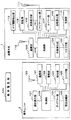
装置本体1は、例えばGPS受信機や自立航法測位装置などから構成される測位部、地図データベース、経路探索部などからなる一般的なナビゲーション部101と、ナビゲーション部101で探索された経路案内の表示などを行なう、液晶表示パネルなどからなる本体表示部102と、操作ユニット2と無線で通信を行う本体通信部103と、操作ユニット2が装置本体1に電気的に装着されているか離脱されているかを検出する脱着検出部104と、操作ユニット2と電気的に結合されるコネクタ部105と、装置本体1に振動が加えられたことを検出する盗難検出手段としての振動検出部106と、振動検出部106の検出開始動作を遅らせるタイマー部107と、操作ユニット2から各種の操作が行われる際に、対応する装置本体1の所有者による操作ユニット2からの操作か否かの認証を行う認証部108と、車のドアがキーやキーレスエントリーシステムによって正しく開成されたかを検出するドア開閉検出部113と、これらの各部の制御を行うCPUからなる本体制御部109と、これらに電源を供給する電源部110とから構成される。
The apparatus
本体通信部103内には、主に車内での遠隔操作時に使用される赤外線通信部を有すると共に、車外での無線通信時に使用される装置本体1に内蔵されたアンテナ112を備えている。
The main
なお、111はナビゲーション動作に用いられる、GPS衛星などから信号を受信するアンテナである。
また、電源部110は、エンジンキーがオフになった場合でも、電源を供給し続けることのできるバックアップ電源も有している。
The
一方、操作ユニット2は、目的地入力や探索条件設定などナビゲーション動作のための入力を行う操作部120と、装置本体1と無線で通信を行う通信部121と、装置本体1から送信された警報信号に基づいて使用者へ鳴音などで警報を発する警報部122と、警報部122で警報が所定時間発せられても使用者から何らの応答もない場合に自動的にダイアル回線に接続して、例えば使用者の携帯電話機123などを発呼するダイアラー部124と、ダイアラー部124で発呼したダイアル発信を電話回線に接続する電話接続部125と、装置本体1に電気的に接続されるコネクタ部126と、操作ユニット2での操作内容などが表示される操作表示部127と、これら各部を制御する制御部128とから構成される。
On the other hand, the
通信部121内には、主に車内での遠隔操作時に使用される赤外線通信部を有すると共に、車外での無線通信時に使用される操作ユニット2に内蔵されたアンテナ129を備えている。
The
また、警報部122はナビゲーション動作における音声発生のためのスピーカの機能も有している。
The
以上のように構成された本実施の形態では、まず運転中は、操作ユニット2が装置本体1に装着されるか、または取り外されて、以下のようにして通常のナビゲーション動作が行われている。
In the present embodiment configured as described above, first, during operation, the
操作ユニット2が装置本体1に装着されている場合は、操作ユニット2のコネクタ部126が装置本体1のコネクタ部105と電気的に結合されて、操作部120からの操作信号は制御部128の制御に基づいてコネクタ部126を介して装置本体1に送られ、装置本体1のコネクタ部105で受けた操作信号は本体制御部109の制御に基づいてナビゲーション部101に送られ、アンテナ111を利用して通常のナビゲーション動作が行われる。
When the
操作ユニット2が装置本体1から取り外されている場合は、装置本体1の脱着検出部104が操作ユニット2が取り外されていることを検出し、制御部128の制御に基づいて、操作ユニット2の操作部120からの操作信号は、電波や赤外線により通信部121およびアンテナ129を介して装置本体1に送られ、さらに本体制御部109の制御により装置本体1のアンテナ112および本体通信部103を介してナビゲーション部101に伝達され、上記と同様にナビゲーション動作が行われる。
When the
次に、運転を停止し、車を、例えば自宅の駐車場に駐車して、運転者や同乗者が車を離れて以降の動作について、図2のフローチャートを用いて説明する。 Next, the operation after the driving is stopped, the car is parked in a parking lot at home, for example, and the driver or passenger leaves the car will be described with reference to the flowchart of FIG.
まず、エンジンキーを切ることによってカーナビゲーション装置の装置本体1の電源をオフし(S201)、運転者は操作ユニット2を携帯して降車して操作ユニット2を自宅などの宅内に持ち込む。またその後、車を使わずに外出する際には、操作ユニット2の電話接続部125を電話回線などにモジュラージャックなどにより接続して外出する。この場合、ダイアラー部124のダイアル先を運転者の携帯電話番号などに設定しておく。
First, by turning off the engine key, the power of the
なお、外出しなくても操作ユニット2の電話接続部125を電話回線などにモジュラージャックなどにより接続しておくことも可能である。
Note that the
電源のオフにより電源部110は、走行中に充電されたバックアップ電源に切り替り、本体制御部109は電源部110の電源オフを検知して、警報機能を動作させるまでの時間をタイマー部107で計数し始める(S202)。タイマー部107で計数する時間は、例えば5分から10分程度であって、この間に運転者や同乗者が降車して車から離れるのに十分な時間である。
When the power is turned off, the
タイマー部107での計数が終了すると、本体制御部109が計数終了を検知して振動検出部106に電源を供給するなどして振動検出動作を開始し(S203)、振動検出部106は駐車中の装置本体1の振動の有無を判断する(S204)。
When the
車が駐車されて運転者が車から離れている状態で、車内のカーナビゲーション装置を盗むために、盗人が駐車中の車の窓ガラスを割ったり、車錠を強制的に破壊しようとした場合、振動検出部106が、盗難情報としての、装置本体1の振動を検知する(S204のY)。振動検出部106が振動を検出すると、その検出結果に基づいて、装置本体1の本体制御部109が、電波や赤外線などによって、警報信号を本体通信部103およびアンテナ112を介して操作ユニット2に送信する(S205)。
If a car is parked and the driver is away from the car, and the thief tries to break the window glass of the parked car or forcibly destroy the car lock, The
運転者が携帯している、または宅内に置かれている操作ユニット2側では、装置本体1から送信された警報信号を、制御部128がアンテナ129および通信部121を介して受信する(S206)。
On the
操作ユニット2では、受信した警報信号によって警報部122から鳴音によって警報を発生し(S207)、駐車中の車に異常があったことを運転者や車の所有者などに知らせる。
In the
電波による送受信の場合、遮へい物の有無にも影響されるが、装置本体1と操作ユニット2の間は、100〜500m離れていても、送受信可能であり、自宅の家屋内と自宅の駐車場、あるいはマンションの部屋とマンションの屋外駐車場の間での送受信が可能である。 In the case of transmission / reception by radio waves, it is also affected by the presence or absence of a shielding object. Or, transmission / reception is possible between the apartment room and the outdoor parking lot of the apartment.
さて、運転者や車の所有者などが操作ユニット2からの警報に気付いた場合、運転者などは操作ユニット2の操作部120で警報解除のキーを押して警報を解除し(S208のY)、その後、駐車してある車のところまで駆けつけるなどしてカーナビゲーション装置の盗難異常を解決する。
Now, when the driver or the owner of the car notices an alarm from the
警報が操作ユニット2から発せられていても、運転者や車の所有者などが操作ユニット2から離れていて警報に気付かず、あるいは車を使わず外出していて警報が解除されなかった場合(S208のN)、操作ユニット2の制御部128での制御に基づいて、所定時間経過の後に、ダイアラー部124が駆動され、電話接続部125を介して電話回線に接続され、運転者や車の所有者などの携帯電話123で発呼して、駐車中の車に異常があったことを知らせる。
Even if an alarm is issued from the
発呼を受けた運転者や車の所有者などは、駐車してある車のところまで駆けつけるなどしてカーナビゲーション装置の盗難異常を解決する。その際に、装置本体1に設けられた警報解除キー(図示せず)をオンして、例えば振動検出部106への電源供給を切断して警報を解除する(S209)。
The driver who received the call, the owner of the car, and the like solve the theft abnormality of the car navigation device by rushing to the parked car. At that time, an alarm release key (not shown) provided in the apparatus
ところで、S204で装置本体1の振動検出部106が振動を検出しなかった場合(S204のN)、すなわち次に車を運転するまでに駐車中の車に異常はなかったことになる
。したがって、ドアキーやキーレスエントリーなどにより合法的に車のドアが開けられると、ドア開閉検出部113がドアの開成を検出して、装置本体1の本体制御部109の制御により振動検出部106への電源供給停止などが行なわれて振動検出動作が停止される(S210)。
By the way, when the
その後、エンジンキーをオンにすることにより、装置本体1の電源がオンされる(S211)。
Thereafter, by turning on the engine key, the power of the apparatus
装置本体1の電源がオンされて操作ユニット2によって操作を開始しようとすると、認証部108が動作して、操作されようとしている操作ユニット2が装置本体1に適合するものかどうかをチェックし(S212)、適合するならば、以降、その操作ユニット2によりナビゲーション動作の操作を行う(S213)。適合しない場合は、その操作ユニット2ではナビゲーション動作を操作できない。
When the power of the apparatus
以上のように、本実施の形態では、通常はナビゲーション動作を行い、車から運転者が離れる際には、装置本体1から操作ユニット2を取り外し運転者などが携帯することで、ナビゲーション装置の盗難が発生した場合に、携帯している操作ユニット2で警報が発せられ、即座に盗難対策を行うことができる。
As described above, in the present embodiment, the navigation operation is normally performed, and when the driver leaves the car, the
また、駐車中の車の窓を割ったり、車錠を強制的に破壊したり、不法に開錠する行為は、車を盗難する場合と同じであるので、カーナビゲーション装置の装置本体1の盗難防止は車の盗難防止も兼ねている。
Moreover, since the act of breaking the window of the parked car, forcibly destroying the car lock, or illegally unlocking the car is the same as the case of stealing the car, the
さらに、操作ユニット2の電話接続部125を電話回線に接続しておけば、警報を発しても運転者などが何らの応答もしない場合や、操作ユニットを宅内に置いたまま車を使用せずに外出した場合に、自動的に、例えば運転者の携帯電話機などに通報して盗難を伝えるができる。
Furthermore, if the
また、操作ユニット2が車内に放置された時に盗難に遭った場合は、車の窓ガラスなどの破壊と同時に盗人の目の前の操作ユニット2が警報を発することになり、また、車内に設置された装置本体1が動作しないものだとわからなかった場合に盗難に遭ったとしても、身近にある操作ユニット2に警報が発せられるので、いずれの場合でも高い盗難防止の効果を得ることができる。
If the
なお、上記実施の形態における振動検出部106での振動検出は、車の駐車中は常時行われていても良いが、消費電力の低減のため、例えば数秒毎のように間欠的に行うようにしても良い。
The vibration detection by the
また、上記実施の形態における警報部122での警報は、本実施の形態のように音でも良いし、その他光や振動など各種の方法で行うことが可能である。
Further, the alarm in the
また、上記実施の形態では、運転者がエンジンキーをオフして装置本体1の電源がオフされてから、所定時間経過後に振動検出が開始されるように、タイマー部107は時間を計数したが、これ以外に、車のドアの閉成や室内灯の消灯を検出してから所定時間を計数するようにすることも可能であり、運転者などが降車してから完全に車から離れた程度の時間を計数するように設定すればよい。
In the above embodiment, the
また、上記実施の形態では、警報を発しても運転者から何らの応答がない場合は、運転者の携帯電話機などに通報したが、これは携帯電話機でなくても自宅の固定電話機や運転者や家族などがいる場所の電話機を発呼するようにしてもよい。 Also, in the above embodiment, if there is no response from the driver even if an alarm is issued, the driver's mobile phone is reported, but this is not a mobile phone, but this is a home fixed phone or driver You may make it call the telephone of the place where there is a family.
特に、屋内にいて操作ユニット2から離れる場合などは、運転者や家族などがいる場所の電話機を発呼するようにすればよい。
In particular, when the user is indoors and is away from the
携帯電話機や固定電話機などに発呼する場合は、発呼するだけでメッセージはなくても、当事者であればそれだけで緊急事態であることがわかるので構わない。メッセージを付加したり、最寄の警察署に通達したりすることも可能であるが、それだけ高機能、高価格になる。 When a call is made to a mobile phone, a fixed phone, or the like, even if there is no message just by making a call, the party may know that it is an emergency situation. It is possible to add a message or notify the nearest police station, but it is highly functional and expensive.
さらにまた、本実施の形態では、車載装置がカーナビゲーション装置の場合について説明したが、それ以外に、本発明は、テレビやDVDなどの各種の車載装置に適用されることは言うまでもない。 Furthermore, although the case where the in-vehicle device is a car navigation device has been described in the present embodiment, it goes without saying that the present invention is applied to various in-vehicle devices such as a television and a DVD.
さらにまた、上記実施の形態では、警報部122を操作ユニット2だけに設けたが、警報部122以外の警報手段を装置本体1に設けても、上記したのと同様に盗人の前でも警報を発することになり、本発明の効果がより高められる。
Furthermore, in the above embodiment, the
図3は本発明の一実施の形態であるカーナビゲーション装置を示す斜視図であって、本実施の形態のカーナビゲーション装置は、装置本体1は、例えば車両のダッシュボード上に設置せられ、上述したように装置本体1の操作を行う操作ユニット2は、装置本体1に着脱可能に設けられ、操作ユニット2の装置本体1への装着時には、装置本体1と一体結合された樹脂製の背面部303に固定される。
FIG. 3 is a perspective view showing a car navigation apparatus according to an embodiment of the present invention. In the car navigation apparatus according to this embodiment, the apparatus
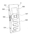
本体装置1の正面の殆どの部分は液晶パネルを用いた本体表示部304で構成され、操作ユニット2には本体装置1に操作指示をする機能キー305と、操作指示内容が表示される操作表示部306と、操作表示部306で表示された操作入力内容を、上下左右を押して選択し、中央を押して決定する決定キー307と、本体表示部304に表示される地図の大きさ(広域、詳細など)を決める地図縮尺キー308と、本体表示部304に地点(現在地、行き先など)を入力するための地点キー309とが設けられている。
Most of the front surface of the
さらに、操作ユニット2には、装置全体の電源オンおよび電源オフの切り替えを行なう電源キー310と、操作ユニット2の警報部122で鳴音によって警報が発せられた場合に鳴音を停止する警報解除キー311が設けられている。
Further, the
すなわち、機能キー305、決定キー307、地図縮尺キー308、地点キー309、電源キー310、警報解除キー311は、図1に示す操作部120を構成している。
That is, the
また、機能キー305は、本実施の形態では、操作表示部127に表示される画面を前の画面に戻すための「戻る」キー、操作表示部127に操作の機能などを表示する「メニューキー」、操作表示部127や本体表示部102に渋滞箇所を表示させる「渋滞キー」、本体表示部102に表示される地図に抜け道を表示させる「抜け道キー」、経路探索結果を記憶させる「オートメモリーキー」から構成され、各キートップは、図に示すように、櫛歯が互い違いに組み合わせられる形状になっている。
In the present embodiment, the
決定キー307、地図縮尺キー308、地点キー309、電源キー310、警報解除キー311は、それぞれの場所を押下することにより操作が行なわれる。
The
なお、装置全体の電源のオン、オフはエンジンキーのオン、オフに連動して行い、また、警報部122からの警報の解除を、機能キー305のうちのメニューキーで操作表示部306に表示させた「警報解除」などの表示を、決定キー307で選択、決定することに
より、電源キー310および警報解除キー311を操作ユニット2からなくすことができる。
The entire apparatus is turned on and off in conjunction with the engine key being turned on and off, and the alarm release from the
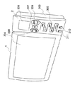
図4は本実施の形態の要部斜視図であって、装置本体1の操作ユニット2との結合部分を示しており、装置本体1の操作ユニット2との結合面401には、操作ユニット2と電気的結合を行なう複数のピン受け部が設けられた凸状のコネクタ部402と、操作ユニット2の位置決めを行う凸状の位置決めピン403、404とが設けられている。
FIG. 4 is a perspective view of the main part of the present embodiment, showing a coupling portion of the apparatus
また、背面部303の操作ユニット2が固定される装着面405には、上下部分に操作ユニット2を勘合固定する樹脂製の固定フック406,407が設けられている。
Further, on the mounting
図5は操作ユニット2の側面部を示す斜視図であって、装置本体1との結合面501には装置本体1のコネクタ部402と勘合し合う、複数の接続ピンが設けられた凹状のコネクタ部502と、装置本体1の位置決めピン403,404が挿入される位置決め穴503,504とが設けられている。なお、コネクタ部502および位置決め穴503,504には複数の接続ピンや穴を覆うようにゴム片を設けてもよい。
FIG. 5 is a perspective view showing a side surface portion of the
このように構成された装置本体1と操作ユニット2は、操作ユニット2を一旦その背面を装置本体1の背面部303の表面にあて、その後本体装置1側に図4の矢印の方向にスライドさせて操作ユニット2の位置決め穴503、504を装置本体1の位置決めピン403、404に結合させれば、図6にその要部断面を示すように、固定フック406は操作ユニット2の固定凹部601に勘合され、コネクタ部402、502は互いに結合されて電気的接続が行なわれ、また操作ユニット2は装置本体1に強固に固定されることになる。なお、図6では位置決め穴503は例えば薄いゴム片602で覆われている。
The apparatus
以上のように本実施の形態では、操作ユニット2は装置本体1に着脱可能であるにもかかわらず、装着状態では外観上は着脱可能であるようには見えない構造となっている。
As described above, in this embodiment, although the
しかしながら、盗難警報を受信するために操作ユニット2を装置本体1から取りはずして携帯すると、操作ユニット2は周囲になんらの突起物のようなものはなく、それだけで十分な機能を持った電子機器の様相を呈し、一方装置本体1の操作ユニット2との着脱部である結合面401や装着面405には、コネクタ部402や位置決めピン403、404、固定フック406、407などの電気的または機械的な着脱構造の結合部が露呈するようになっており、この装置本体だけでは十分な機能を果さない電子機器を思わせる外観となっている。
However, when the
すなわち、盗難警報を受信するため操作ユニット2を取り外して携帯した後の装置本体1の状態が、外観上はナビゲーション装置全体の構成から一部の構成部品が取り外されているように見え、しかも操作ユニット2が車外に持ち出されて車内に放置されないために、このような車内に残った構成部分だけではナビゲーション装置は動作しないという印象を与えるので、操作ユニット2を取り外して車外に持ち出すことはそれだけで装置本体1側に対して盗難抑止効果がある。
That is, the state of the device
なお、上記実施の形態のような形状でなくても、操作ユニット2が装置本体1に装着された状態では車載電子機器の様相を呈するが、携帯するため操作ユニット2を取り外した状態では、外観上、車載電子機器の構成品が欠落しているような様相を呈するように構成されていれば、盗難抑止の効果が得られる。
In addition, even if it is not the shape as in the above embodiment, it looks like an in-vehicle electronic device when the
本発明は、車載装置の操作部が装置本体に対して着脱可能であって、車内あるいは装置
本体に異常が発生した場合に、操作ユニットに車両側での異常事態の発生が通知されるので、カーオーディオ装置やカーナビゲーション装置などに有用である。
In the present invention, the operation unit of the in-vehicle device is detachable from the device main body, and when an abnormality occurs in the vehicle or the device main body, the operation unit is notified of the occurrence of an abnormal situation on the vehicle side. This is useful for car audio devices and car navigation devices.
1 装置本体
2 操作ユニット
101 ナビゲーション部
102、304 本体表示部
103 本体通信部
104 脱着検出部
105、126、402、502 コネクタ部
106 振動検出部
107 タイマー部
108 認証部
109 本体制御部
110 電源部
111、112、129 アンテナ
113 ドア開閉検出部
120 操作部
121 通信部
122 警報部
123 携帯電話機
124 ダイアラー部
125 電話接続部
127、306 操作表示部
128 制御部
303 背面部
305 機能キー
307 決定キー7
308 地図縮尺キー
309 地点キー
310 電源キー
311 警報解除キー
401、501 結合面
403、404 位置決めピン
405 装着面
406、407 固定フック
503、504 位置決め穴
601 固定凹部
602 ゴム片
DESCRIPTION OF
308
Claims (3)
The in-vehicle device according to claim 1, wherein the theft detection means detects vibration of the in-vehicle device main body.
Priority Applications (1)
| Application Number | Priority Date | Filing Date | Title |
|---|---|---|---|
| JP2004259238A JP2006076320A (en) | 2004-09-07 | 2004-09-07 | On-vehicle device |
Applications Claiming Priority (1)
| Application Number | Priority Date | Filing Date | Title |
|---|---|---|---|
| JP2004259238A JP2006076320A (en) | 2004-09-07 | 2004-09-07 | On-vehicle device |
Publications (1)
| Publication Number | Publication Date |
|---|---|
| JP2006076320A true JP2006076320A (en) | 2006-03-23 |
Family
ID=36156153
Family Applications (1)
| Application Number | Title | Priority Date | Filing Date |
|---|---|---|---|
| JP2004259238A Pending JP2006076320A (en) | 2004-09-07 | 2004-09-07 | On-vehicle device |
Country Status (1)
| Country | Link |
|---|---|
| JP (1) | JP2006076320A (en) |
Cited By (4)
| Publication number | Priority date | Publication date | Assignee | Title |
|---|---|---|---|---|
| JP2009161005A (en) * | 2007-12-28 | 2009-07-23 | Sony Corp | On-vehicle equipment mounted with security function, and its security function control method |
| JP2014117971A (en) * | 2012-12-13 | 2014-06-30 | Denso Corp | Tire theft alarm system |
| JP2015212113A (en) * | 2014-05-02 | 2015-11-26 | 株式会社ユピテル | Fitting tool and electronic equipment |
| US20220242365A1 (en) * | 2021-02-02 | 2022-08-04 | Teddy Presher | Kidnapping notification system |
-
2004
- 2004-09-07 JP JP2004259238A patent/JP2006076320A/en active Pending
Cited By (6)
| Publication number | Priority date | Publication date | Assignee | Title |
|---|---|---|---|---|
| JP2009161005A (en) * | 2007-12-28 | 2009-07-23 | Sony Corp | On-vehicle equipment mounted with security function, and its security function control method |
| JP2014117971A (en) * | 2012-12-13 | 2014-06-30 | Denso Corp | Tire theft alarm system |
| US9738254B2 (en) | 2012-12-13 | 2017-08-22 | Denso Corporation | Tire theft alarm system |
| JP2015212113A (en) * | 2014-05-02 | 2015-11-26 | 株式会社ユピテル | Fitting tool and electronic equipment |
| US20220242365A1 (en) * | 2021-02-02 | 2022-08-04 | Teddy Presher | Kidnapping notification system |
| US11780406B2 (en) * | 2021-02-02 | 2023-10-10 | Teddy Presher | Kidnapping notification system |
Similar Documents
| Publication | Publication Date | Title |
|---|---|---|
| US6900723B2 (en) | Anti-theft system for vehicles | |
| US6480098B2 (en) | Remote vehicle control system including common carrier paging receiver and related methods | |
| EP1319563B1 (en) | Antitheft apparatus, antitheft method and program therefor | |
| US5874889A (en) | System and methods for triggering and transmitting vehicle alarms to a central monitoring station | |
| US9102294B2 (en) | Real-time vehicle alarm communication system | |
| WO2000069691A1 (en) | Emergency call system with theft prevention function | |
| JPH05106376A (en) | Keyless entry system | |
| JPH08339484A (en) | Detach with alarm | |
| JP2017027547A (en) | Vehicle crime prevention system | |
| US20050231335A1 (en) | Vehicle alarm remote paging system | |
| JP2006076320A (en) | On-vehicle device | |
| JPH1081205A (en) | Anti-theft device for vehicle | |
| US20040000989A1 (en) | Vehicle monitoring system that uses a cellular telephone to notify of vehicle tampering | |
| JP2006089020A (en) | Receiving device for vehicle | |
| JPH09267718A (en) | Car stereo set | |
| JP3854838B2 (en) | Vehicle locking control device | |
| JPH11139252A (en) | Vehicle communication device | |
| JP2001010448A (en) | Wireless method and device for preventing theft of vehicle | |
| JP2004322748A (en) | Vehicular anti-theft system | |
| JP2001315619A (en) | Vehicle anti-theft warning system | |
| JP2019043477A (en) | Alarm, vehicle control system, warning method and computer program | |
| KR20040031836A (en) | Picture type security system for car | |
| JP2004058802A (en) | Security system | |
| KR20040003766A (en) | Automotive anti theft device with telematics device | |
| JP2001018757A (en) | Theft preventing device for vehicle |