JP2006074162A - Image processing of color image and monochromatic image - Google Patents
Image processing of color image and monochromatic image Download PDFInfo
- Publication number
- JP2006074162A JP2006074162A JP2004252294A JP2004252294A JP2006074162A JP 2006074162 A JP2006074162 A JP 2006074162A JP 2004252294 A JP2004252294 A JP 2004252294A JP 2004252294 A JP2004252294 A JP 2004252294A JP 2006074162 A JP2006074162 A JP 2006074162A
- Authority
- JP
- Japan
- Prior art keywords
- image data
- color
- image
- tone
- conversion
- Prior art date
- Legal status (The legal status is an assumption and is not a legal conclusion. Google has not performed a legal analysis and makes no representation as to the accuracy of the status listed.)
- Pending
Links
- 238000012545 processing Methods 0.000 title claims abstract description 43
- 230000008859 change Effects 0.000 claims abstract description 16
- 238000006243 chemical reaction Methods 0.000 claims description 139
- 230000004048 modification Effects 0.000 claims description 73
- 238000012986 modification Methods 0.000 claims description 73
- 239000003086 colorant Substances 0.000 claims description 21
- 238000000034 method Methods 0.000 claims description 20
- 238000004590 computer program Methods 0.000 claims description 12
- 238000003860 storage Methods 0.000 claims description 10
- 238000002360 preparation method Methods 0.000 claims description 7
- 230000004044 response Effects 0.000 claims description 2
- 238000007639 printing Methods 0.000 description 136
- 239000000976 ink Substances 0.000 description 43
- 238000010586 diagram Methods 0.000 description 17
- 230000006870 function Effects 0.000 description 14
- 101000766246 Homo sapiens Probable E3 ubiquitin-protein ligase MID2 Proteins 0.000 description 9
- 102100026310 Probable E3 ubiquitin-protein ligase MID2 Human genes 0.000 description 9
- 241000238370 Sepia Species 0.000 description 7
- 102100022404 E3 ubiquitin-protein ligase Midline-1 Human genes 0.000 description 5
- 101000680670 Homo sapiens E3 ubiquitin-protein ligase Midline-1 Proteins 0.000 description 5
- 230000008569 process Effects 0.000 description 4
- GGCZERPQGJTIQP-UHFFFAOYSA-N sodium;9,10-dioxoanthracene-2-sulfonic acid Chemical compound [Na+].C1=CC=C2C(=O)C3=CC(S(=O)(=O)O)=CC=C3C(=O)C2=C1 GGCZERPQGJTIQP-UHFFFAOYSA-N 0.000 description 4
- 230000007704 transition Effects 0.000 description 4
- 238000012937 correction Methods 0.000 description 3
- 230000008707 rearrangement Effects 0.000 description 3
- 238000010146 3D printing Methods 0.000 description 2
- 101100283936 Caenorhabditis elegans gsr-1 gene Proteins 0.000 description 2
- 238000013459 approach Methods 0.000 description 2
- 238000004519 manufacturing process Methods 0.000 description 2
- 230000007246 mechanism Effects 0.000 description 2
- 238000012546 transfer Methods 0.000 description 2
- 230000008901 benefit Effects 0.000 description 1
- 238000004891 communication Methods 0.000 description 1
- 230000000694 effects Effects 0.000 description 1
- 239000000463 material Substances 0.000 description 1
- 238000002715 modification method Methods 0.000 description 1
- 230000009466 transformation Effects 0.000 description 1
Images


Classifications
-
- G—PHYSICS
- G06—COMPUTING; CALCULATING OR COUNTING
- G06T—IMAGE DATA PROCESSING OR GENERATION, IN GENERAL
- G06T5/00—Image enhancement or restoration
- G06T5/90—Dynamic range modification of images or parts thereof
- G06T5/92—Dynamic range modification of images or parts thereof based on global image properties
-
- H—ELECTRICITY
- H04—ELECTRIC COMMUNICATION TECHNIQUE
- H04N—PICTORIAL COMMUNICATION, e.g. TELEVISION
- H04N1/00—Scanning, transmission or reproduction of documents or the like, e.g. facsimile transmission; Details thereof
- H04N1/46—Colour picture communication systems
- H04N1/56—Processing of colour picture signals
- H04N1/60—Colour correction or control
-
- H—ELECTRICITY
- H04—ELECTRIC COMMUNICATION TECHNIQUE
- H04N—PICTORIAL COMMUNICATION, e.g. TELEVISION
- H04N1/00—Scanning, transmission or reproduction of documents or the like, e.g. facsimile transmission; Details thereof
- H04N1/40—Picture signal circuits
- H04N1/407—Control or modification of tonal gradation or of extreme levels, e.g. background level
-
- H—ELECTRICITY
- H04—ELECTRIC COMMUNICATION TECHNIQUE
- H04N—PICTORIAL COMMUNICATION, e.g. TELEVISION
- H04N1/00—Scanning, transmission or reproduction of documents or the like, e.g. facsimile transmission; Details thereof
- H04N1/46—Colour picture communication systems
- H04N1/56—Processing of colour picture signals
- H04N1/60—Colour correction or control
- H04N1/6011—Colour correction or control with simulation on a subsidiary picture reproducer
-
- G—PHYSICS
- G06—COMPUTING; CALCULATING OR COUNTING
- G06T—IMAGE DATA PROCESSING OR GENERATION, IN GENERAL
- G06T2207/00—Indexing scheme for image analysis or image enhancement
- G06T2207/10—Image acquisition modality
- G06T2207/10024—Color image
Landscapes
- Engineering & Computer Science (AREA)
- Multimedia (AREA)
- Signal Processing (AREA)
- Physics & Mathematics (AREA)
- General Physics & Mathematics (AREA)
- Theoretical Computer Science (AREA)
- Image Processing (AREA)
- Facsimile Image Signal Circuits (AREA)
- Color Image Communication Systems (AREA)
Abstract
Description
この発明は、画像データの画像の色調を調整する技術に関する。 The present invention relates to a technique for adjusting the color tone of an image of image data.
従来より、画像データの画像の色調を調整し、必要に応じて印刷することができるアプリケーションソフトが存在する。色調の調整においては、具体的には、画像を構成する各画素の色の階調値が改変される。特許文献1および2の画像変換では、入力階調値に対する出力階調値を規定している所定のトーンカーブに従って、画素の階調値を変換している。 Conventionally, there is application software that can adjust the color tone of an image of image data and print it as necessary. In the adjustment of the color tone, specifically, the color gradation value of each pixel constituting the image is modified. In the image conversion of Patent Documents 1 and 2, the gradation value of a pixel is converted according to a predetermined tone curve that defines an output gradation value with respect to an input gradation value.
従来からの銀塩写真愛好家など、モノクロ画像のデータを頻繁に扱い、かつ、その際に微妙な画質の調整を希望するユーザにとっては、微妙な調整が可能な画像処理システムが望ましい。しかし、微妙な調整が可能な画像処理システムは、操作画面の構成も複雑となり、操作も煩雑となる。色調の微妙な調整までは望まない一般ユーザにとっては、そのような画像処理システムを使うことは、煩雑である。 For a user who frequently handles monochrome image data such as a conventional silver salt photograph enthusiast and desires fine adjustment of image quality, an image processing system capable of fine adjustment is desirable. However, in an image processing system capable of delicate adjustment, the configuration of the operation screen becomes complicated and the operation becomes complicated. For a general user who does not want fine adjustment of the color tone, it is complicated to use such an image processing system.
本発明はかかる点に鑑みてなされたもので、一般ユーザが行う作業を煩雑にすることなく、モノクロ画像の処理を行う趣味性の高いユーザの要求を満たす画像処理手段を提供することを主たる目的とする。 SUMMARY An advantage of some aspects of the invention is that it provides an image processing unit that satisfies the demands of users with high hobbies for processing monochrome images without complicating the work performed by general users. And
上記目的を達成するために、本発明は、画像データの画像の色調を改変して新たな画像データを生成させる際に、以下の処理を行う。まず、画像データの画素の色を改変するためのパラメータであって、互いに異なる改変内容に対応する複数の改変候補パラメータの中から、ユーザに、たとえば、一つのパラメータを選択させる。そして、選択されたパラメータに応じて、画像の色調を改変する対象である対象画像データから、対象画像データとは少なくとも一部の画素の色が異なる改変画像データを生成する。 In order to achieve the above object, the present invention performs the following process when generating new image data by modifying the color tone of the image of the image data. First, it is a parameter for modifying the color of a pixel of image data, and the user is allowed to select, for example, one parameter from among a plurality of modification candidate parameters corresponding to different modification contents. Then, in accordance with the selected parameter, modified image data in which the colors of at least some of the pixels are different from the target image data is generated from the target image data that is a target for modifying the color tone of the image.
複数の改変候補パラメータは、カラー画像データの画素の階調値を変換するためのNc個(Ncは正の整数)のカラー画像用改変候補パラメータと、モノクロ画像データの画素の階調値を変換するためのNm個(NmはNcより大きい整数)のモノクロ画像用改変候補パラメータと、を含む。なお、カラー画像用改変候補パラメータと、モノクロ画像用改変候補パラメータとは、互いに一部が重複していてもよい。 The plurality of modification candidate parameters convert Nc (Nc is a positive integer) color image modification candidate parameter for converting the gradation value of the pixel of the color image data and the gradation value of the pixel of the monochrome image data. Nm (Nm is an integer larger than Nc) monochrome image modification candidate parameters. The color image modification candidate parameter and the monochrome image modification candidate parameter may partially overlap each other.
対象画像データがカラー画像データであるときには、ユーザに、Nc個のカラー画像用改変候補パラメータの中から、たとえば一つのパラメータを選択させる。また、対象画像データがモノクロ画像データであるときには、ユーザに、Nm個のモノクロ画像用改変候補パラメータの中から、たとえば一つのパラメータを選択させる。このような態様とすれば、モノクロ画像については、カラー画像の場合よりも多くの選択肢の中から色の改変内容を選択できる。よって、一般ユーザが行う作業を煩雑にすることなく、モノクロ画像の印刷を行う趣味性の高いユーザの要求を満たすことができる。 When the target image data is color image data, the user is allowed to select, for example, one parameter from among the Nc color image modification candidate parameters. Further, when the target image data is monochrome image data, the user is allowed to select, for example, one parameter from among the Nm monochrome image modification candidate parameters. With such an aspect, for a monochrome image, the color modification content can be selected from a larger number of options than in the case of a color image. Therefore, it is possible to satisfy a user's request with high hobby that prints a monochrome image without complicating the work performed by a general user.
なお、複数の改変候補パラメータは、階調変換特性を表すパラメータであることが好ましい。たとえば、複数の改変候補パラメータは、所定の階調値系列の階調値を同じ階調値系列の階調値に変換する改変にそれぞれ対応するパラメータとすることができる。所定の階調値系列は、たとえば、互いに明度が異なる複数の色の集合である階調値の系列とすることができる。たとえば、複数の改変候補パラメータは、黒から白までの無彩色を表す0〜255の階調値のうちのいずれかの階調値を、同じ無彩色を表す0〜255のいずれかの階調値に変換する改変に、それぞれ対応するパラメータとすることができる。この改変は、例えば、無彩色の階調値0〜255のうちの1〜32の階調値のみを、他の異なる値に変える改変とすることができる。
The plurality of modification candidate parameters are preferably parameters representing tone conversion characteristics. For example, the plurality of modification candidate parameters can be parameters respectively corresponding to modifications for converting a gradation value of a predetermined gradation value series into a gradation value of the same gradation value series. The predetermined gradation value series can be, for example, a series of gradation values that is a set of a plurality of colors having different brightness values. For example, the plurality of modification candidate parameters include any one of gradation values from 0 to 255 representing an achromatic color from black to white, and any gradation from 0 to 255 representing the same achromatic color. Each parameter corresponding to a modification to be converted into a value can be used. This modification can be, for example, a modification in which only the gradation values 1 to 32 of the
また、以下のような処理を行うことも好ましい。すなわち、画素の色の改変を実現するための変換曲線であって、入力階調値に対応する出力階調値を与える変換曲線を、選択されたパラメータに応じて準備する。そして、対象画像データがモノクロ画像データであるときには、変換曲線のうち入力階調値が所定の範囲内にある第1の部分を改変せずに第2の部分を改変するための部分調整入力画面をユーザに提供す。一方、対象画像データがカラー画像データであるときには、部分調整入力画面をユーザに提供しない態様とすることもできる。 It is also preferable to perform the following processing. That is, a conversion curve for realizing the modification of the color of the pixel, which provides an output tone value corresponding to the input tone value, is prepared according to the selected parameter. When the target image data is monochrome image data, a partial adjustment input screen for modifying the second portion without modifying the first portion of the conversion curve whose input gradation value is within the predetermined range. To the user. On the other hand, when the target image data is color image data, a mode in which the partial adjustment input screen is not provided to the user may be adopted.
そして、部分調整入力画面を介したユーザの指示に応じて変換曲線の第2の部分を改変する。その後、変換曲線に基づいて対象画像データの画素の階調値を改変する。このような態様とすれば、ユーザは、モノクロ画像を処理する場合に、カラー画像に比べてより詳細に色の改変内容を指定することができる。 And the 2nd part of a conversion curve is changed according to a user's instruction via a partial adjustment input screen. Thereafter, the gradation value of the pixel of the target image data is modified based on the conversion curve. According to such an aspect, the user can specify the color modification content in more detail than the color image when processing a monochrome image.
なお、第2の部分は、入力階調値がとりうる値の範囲のうち上から40%までの範囲に含まれる領域に相当する部分とすることが好ましい。また、第2の部分は、入力階調値がとりうる値の範囲のうち下から25%までの範囲に含まれる領域に相当する部分とすることも好ましい。 The second portion is preferably a portion corresponding to a region included in the range from the top to 40% of the range of values that the input gradation value can take. The second portion is preferably a portion corresponding to a region included in the range from the bottom to 25% of the range of values that the input gradation value can take.
また、変換曲線の第2の部分を改変する際には、変換曲線の出力階調値の変化が、L*a*b*表色系のL*で表したときにプラスマイナス10の範囲内となるように改変することが好ましい。このような態様とすれば、改変によって画像が不自然なものとなってしまうことを防止できる。 When the second part of the conversion curve is modified, the change in the output gradation value of the conversion curve is within a range of plus or minus 10 when expressed by L * a * b * color system L * . It is preferable to modify so that. With such an aspect, it is possible to prevent the image from becoming unnatural due to the modification.
なお、以下のような態様とすることも好ましい。すなわち、対象画像データの画像を印刷する印刷媒体の種類の情報に応じて、変換曲線の出力階調値の改変の許容範囲を決定する。そして、変換曲線の第2の部分を改変する際には、変換曲線の出力階調値の変化の大きさが許容範囲内となるように変換曲線を改変する。このような態様とすれば、暗い色や明るい色を表現しにくい印刷媒体においては、狭い範囲の階調値で画像を表現するように画像の色の改変を行うことができる。 In addition, it is also preferable to set it as the following aspects. In other words, the allowable range of modification of the output gradation value of the conversion curve is determined according to the information on the type of print medium on which the image of the target image data is printed. Then, when modifying the second part of the conversion curve, the conversion curve is modified so that the change in the output tone value of the conversion curve is within the allowable range. With such an aspect, the color of the image can be modified so that the image is expressed with a narrow range of gradation values on a print medium that is difficult to express a dark color or a light color.
また、変換曲線の第2の部分を改変する際には、入力階調値がとりうる値のうちで最も高い値を、出力階調値がとりうる値で最も高い値よりも低い値に変換するように改変することも好ましい。このような変換内容とすれば、画像内の全領域に明度が一定値以下である色が付されることになる。このため、画像の周りの部分に階調値の最大値に相当する色が付されている場合に、画像の外延を明確にすることができる。 Further, when modifying the second part of the conversion curve, the highest value of the input gradation values can be converted to a value lower than the highest value of the output gradation values. It is also preferable to make modifications. With such conversion contents, a color having a lightness of a certain value or less is added to the entire area in the image. For this reason, when the color corresponding to the maximum value of the gradation value is given to the portion around the image, the extension of the image can be clarified.
また、変換曲線の第2の部分を改変する際には、入力階調値がとりうる値のうちで最も低い値を、出力階調値がとりうる値で最も低い値よりも高い値に変換するように改変することも好ましい。 Further, when modifying the second part of the conversion curve, the lowest value of the input gradation values can be converted to a value higher than the lowest value of the output gradation values. It is also preferable to make modifications.
また、対象とする画像データがモノクロ画像データである場合には、以下のような処理を行うことが好ましい。すなわち、対象画像データがモノクロ画像データであるときに、変換曲線に応じてモノクロ画像用変換テーブルを生成する。このモノクロ画像用変換テーブルは、モノクロ画像データを、所定の第1の表色系の階調値で表された画像データに変換するための変換テーブルであって、階調値で表現された無彩色のうち少なくとも一部を明度の異なる色に改変する変換テーブルである。そして、このモノクロ画像用変換テーブルに基づいて、対象画像データを改変画像データに変換する。このような態様とすれば、変換テーブルを改変することによって、変換曲線に応じた画像データの改変を実現することができる。 When the target image data is monochrome image data, it is preferable to perform the following processing. That is, when the target image data is monochrome image data, a monochrome image conversion table is generated according to the conversion curve. This monochrome image conversion table is a conversion table for converting monochrome image data into image data represented by gradation values of a predetermined first color system, and is a blank table represented by gradation values. It is the conversion table which changes at least one part among chromatic colors into the color from which brightness differs. Based on the monochrome image conversion table, the target image data is converted into modified image data. With such an aspect, modification of the image data according to the conversion curve can be realized by modifying the conversion table.
なお、変換曲線に応じてモノクロ画像用変換テーブルを生成する際には、あらかじめ用意された基準となるモノクロ画像用変換テーブルを変換曲線に応じて改変して、変換曲線に応じたモノクロ画像用変換テーブルを生成することが好ましい。そして、基準となるモノクロ画像用変換テーブルは、色をL*a*b*表色系で表したときに、前記変換曲線に応じて改変する前の色のL*の値が、改変前の色を表す入力階調値の増加に対して線形に増加する部分を含むモノクロ画像用変換テーブルとすることが望ましい。そのようなモノクロ画像用変換テーブルを用いて画像データの変換を行えば、前述の第2の部分の階調値において色の違いが分かりやすくなるように、色の改変を行うことができる。 When generating a monochrome image conversion table according to the conversion curve, the monochrome image conversion table prepared in advance is modified according to the conversion curve to convert the monochrome image according to the conversion curve. It is preferable to generate a table. In the monochrome image conversion table, when the color is expressed in the L * a * b * color system, the L * value of the color before being changed according to the conversion curve is It is desirable to use a monochrome image conversion table that includes a portion that increases linearly with respect to an increase in the input tone value representing the color. If image data is converted using such a monochrome image conversion table, the color can be modified so that the color difference can be easily understood in the gradation values of the second portion.
また、カラー画像データが、各画素の色が第2の表色系の階調値で表されている画像データである場合には、以下のような処理を行うことが好ましい。すなわち、対象画像データがカラー画像データであるときに、変換曲線に応じてカラー画像用変換テーブルを生成する。このカラー画像用変換テーブルは、カラー画像データを、第2の表色系とは異なる第3の表色系の階調値で表された画像データに変換するための変換テーブルであって、第2の表色系の階調値で表された色のうち少なくとも一部を他の色に改変する変換テーブルである。 In addition, when the color image data is image data in which the color of each pixel is represented by a gradation value of the second color system, it is preferable to perform the following processing. That is, when the target image data is color image data, a color image conversion table is generated according to the conversion curve. This color image conversion table is a conversion table for converting color image data into image data represented by gradation values of a third color system different from the second color system. 2 is a conversion table for modifying at least a part of colors represented by gradation values of 2 color system to another color.
そして、対象画像データがカラー画像データであるときに、カラー画像用変換テーブルに基づいて、対象画像データを改変画像データに変換する。なお、第3の表色系は、階調値が、互いに異なるMc個(Mcは正の整数)の値をとりうる表色系である。そして、第1の表色系は、階調値が、互いに異なるMm個(Mmは、Mcよりも大きい整数)の値をとりうる表色系である。このような態様とすれば、モノクロ画像データについては、より微細な階調の違いを再現することができる。 Then, when the target image data is color image data, the target image data is converted into modified image data based on the color image conversion table. The third color system is a color system that can take Mc values (Mc is a positive integer) whose gradation values are different from each other. The first color system is a color system that can take Mm values (Mm is an integer larger than Mc) having different gradation values. With such an aspect, a finer gradation difference can be reproduced for monochrome image data.
なお、本発明は、種々の形態で実現することが可能であり、例えば、画像データ生成方法および装置、画像データの色改変の補助方法および装置、印刷制御方法および装置、印刷方法および装置、それらの方法または装置の機能を実現するためのコンピュータプログラム、そのコンピュータプログラムを記録した記録媒体等の形態で実現することができる。 The present invention can be realized in various forms, for example, an image data generation method and apparatus, an image data color modification auxiliary method and apparatus, a print control method and apparatus, a printing method and apparatus, and the like. The present invention can be realized in the form of a computer program for realizing the function of the method or apparatus, a recording medium on which the computer program is recorded, or the like.
A.第1実施例.
A1.全体の構成:
図1は、第1実施例の印刷システムのソフトウェアの構成を示すブロック図である。コンピュータ90では、所定のオペレーティングシステムの下で、アプリケーションプログラム95が動作している。また、オペレーティングシステムには、ビデオドライバ91やプリンタドライバ96が組み込まれている。
A. First embodiment.
A1. Overall configuration:
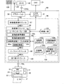
FIG. 1 is a block diagram illustrating a software configuration of the printing system according to the first embodiment. In the
アプリケーションプログラム95は、マウス130やキーボード120から入力されるユーザの指示に応じて、レッド(R),グリーン(G),ブルー(B)の3色の色成分からなる原画像データORGをCD−R140から読み込む。そして、ユーザの指示に応じて、原画像データORGに画像のレタッチなどの処理を行う。アプリケーションプログラム95は、処理を行った画像を、ビデオドライバ91を介してCRTディスプレイ21に画像を表示する。また、アプリケーションプログラム95は、ユーザからの印刷指示を受け取ると、プリンタドライバ96に印刷指示を出し、処理を行った画像を初期画像データPIDとしてプリンタドライバ96に出力する。初期画像データPIDは、たとえば、各画素の色が、それぞれ0〜255の値をとるレッド、グリーン、ブルーの3個の階調値の組み合わせで表された画像データである。
The application program 95 converts the original image data ORG composed of the three color components of red (R), green (G), and blue (B) into CD- in accordance with a user instruction input from the
また、アプリケーションプログラム95において、原画像データORGを、明度を表す0〜255の階調値で表された白黒画像の初期画像データPIDに変換することもある。さらに、原画像データORG自体が、そのような白黒画像であることもある。そのような場合には、初期画像データPIDも明度を表す0〜255の階調値で表された白黒画像のデータとなる。 In the application program 95, the original image data ORG may be converted into initial image data PID of a black and white image represented by a gradation value of 0 to 255 representing brightness. Further, the original image data ORG itself may be such a monochrome image. In such a case, the initial image data PID is also black-and-white image data represented by gradation values from 0 to 255 representing brightness.
プリンタドライバ96は、初期画像データPIDをアプリケーションプログラム95から受け取る。プリンタドライバ96は、これをプリンタ22が処理可能な印刷画像データFNL(ここではシアン、マゼンダ、イエロー、第1〜第3の無彩色インクの6色についての多値化された信号)に変換する。なお、第1〜第3の無彩色インクは、その順に明度が高い無彩色インクである。
The
図1に示した例では、プリンタドライバ96の内部には、解像度変換モジュール97と、色変換モジュール98と、候補ガンマ値格納部102と、色変換テーブル104と、ハーフトーンモジュール99と、並べ替えモジュール100とが備えられている。
In the example shown in FIG. 1, the
解像度変換モジュール97は、初期画像データPIDの解像度をプリンタ22で印刷を行う際の解像度に変換する。色変換モジュール98は、カラー画像の印刷においては、色変換テーブル104の印刷用3次元ルックアップテーブル104aを参照しつつ、RGBの階調値で各画素の色が現されている画像データMID1を、プリンタ22が使用するシアン(C)、マゼンダ(M)、イエロー(Y)、第1〜第3の無彩色インク(K1〜K3)の階調値で各画素の色が表された画像データMID2に変換する。また、色変換モジュール98は、白黒画像の印刷においては、色変換テーブル104の印刷用1次元ルックアップテーブル104cを参照しつつ、白黒の画像データMID1を、シアン(C)、マゼンダ(M)、イエロー(Y)、第1〜第3の無彩色インク(K1〜K3)の階調値で各画素の色が表された画像データMID2に変換する。
The resolution conversion module 97 converts the resolution of the initial image data PID into the resolution used when printing by the
なお、初期画像データPIDが白黒画像である場合に、これに所定の色調を付して印刷する場合がある。白黒画像に所定の色調を付して印刷する場合については、第2実施例で説明する。 When the initial image data PID is a monochrome image, it may be printed with a predetermined color tone. The case of printing a monochrome image with a predetermined color tone will be described in the second embodiment.
ハーフトーンモジュール99は、各画素の各色の濃度が各色の階調値で表された画像データMID2にハーフトーン処理を行うことによって、各色の濃度が各画素におけるドットの有無で表される画像データMID3(「印刷データ」または「ドットデータ」とも呼ぶ)に変換する。
The
こうして生成された画像データMID3は、並べ替えモジュール100によりプリンタ22に転送すべきデータ順に並べ替えられて、最終的な印刷画像データFNLとして出力される。
The image data MID3 generated in this way is rearranged in the order of data to be transferred to the
プリンタ22は、紙送りモータによって用紙Pを搬送する機構と、キャリッジモータによってキャリッジ31を用紙Pの搬送方向SSと垂直な方向MSに往復動させる機構と、キャリッジ31に搭載されインクの吐出およびドット形成を行う印刷ヘッド28と、各種の設定データを格納しているP−ROM42と、これらの紙送りモータ,キャリッジモータ,印刷ヘッド28、P−ROM42および操作パネル32を制御するCPU41とから構成されている。プリンタ22は、印刷画像データFNLを受け取って、印刷画像データFNLに応じてシアン(C)、マゼンダ(M)、イエロー(Y)、第1〜第3の無彩色インク(K1〜K3)で印刷媒体上にドットを形成し、印刷を実行する。
The
なお、本明細書においては、「印刷装置」とは、狭義にはプリンタ22のみをさすが、広義にはコンピュータ90とプリンタ22とを含む印刷システム全体を表す。
In the present specification, the “printing apparatus” refers only to the
A2.白黒画像の階調値変換:
まず、初期画像データPIDが、各画素の色が明度を表す0〜255の階調値で表されている白黒画像のデータである場合の印刷について説明する。ここでは、初期画像データPIDの白黒画像に対し、まず濃淡の調整を行い、その後に印刷を実行する。なお、本明細書において「色」とは、有彩色だけではなく無彩色も含む。互いに濃度の異なるグレーは、互いに「異なる色」である。
A2. Tone value conversion for black and white images:
First, printing in the case where the initial image data PID is monochrome image data in which the color of each pixel is represented by a gradation value of 0 to 255 representing lightness will be described. Here, for the monochrome image of the initial image data PID, first, density adjustment is performed, and then printing is executed. In this specification, “color” includes not only chromatic colors but also achromatic colors. Grays having different densities are “different colors”.
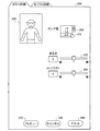
図2は、プリンタドライバ96の色調設定画面200を示す説明図である。アプリケーションプログラム95から印刷指示が出されると、CRTディスプレイ21にプリンタドライバ96のユーザインターフェイス画面が表示される。このプリンタドライバ96のユーザインターフェイス画面において、ユーザがモノクロ印刷のタブ(図2の左上参照)を選択すると、CRT21の画面上に、図2に示す色調設定画面200が表示される。
FIG. 2 is an explanatory diagram showing the color
色調設定画面200は、ガンマ補正を行う場合にガンマ値を指定するガンマ値指定部260と、白黒画像に付す色調を指定するためのカラーサークル210と、白黒画像に付す色調の設定をあらかじめ用意されたものの中から選択するためのカラートーン選択部250と、色見本画像を表示するための見本画像表示領域220と、を有する。
The
なお、第1実施例においては、白黒画像に色調を付さないで、そのまま白黒画像として印刷する場合について説明する。このため、カラーサークル210とカラートーン選択部250は操作されないものとする。よって、これらの説明は省略する。白黒画像に色調を付して印刷する場合については、第2実施例で説明する。
In the first embodiment, a case will be described in which a black and white image is printed as it is without adding a color tone. For this reason, the
色調設定画面200は、さらに、画像の明るさを規定する明度パラメータを指定するための明度スケール232と、画像のコントラストを規定するコントラストパラメータを指定するためのコントラストスケール234と、階調値0〜32の比較的暗い画素の濃淡を調整するための暗部トーン調整スケール236と、階調値192〜255の比較的明るい画素の濃淡を調整するための明部トーン調整スケール238と、を有する。色調設定画面200は、さらに、画像データにおける最も明るい色の明るさを調整するためのハイライトポイント・チェックボックス240を有する。
The color
色調設定画面200は、さらに、上述のガンマ値指定部260、各スケール232〜238などを通じて設定された色調に従って、初期画像データPIDに対して画像変換を行った場合の色見本画像を見本画像表示領域220に表示させるためのプレビューボタン270を有する。そして、印刷処理を中止するためのキャンセルボタン280と、設定されたパラメータを確定し、それらのパラメータに沿って画像変換を行って印刷を実行させるためのプリントボタン290と、を有する。
The color
ユーザは、マウス130を介してカーソルCSを操作して、色調設定画面200内のガンマ値指定部260においてガンマ値を指定することができる。白黒画像の印刷用としては、1.4〜2.4まで0.2きざみの6個のガンマ値の候補が、候補ガンマ値格納部102内に予め用意されている。ユーザがガンマ値指定部260をクリックすると、図2に示すように、それらのガンマ値の候補が色調設定画面200に提示される。ユーザは、マウス130を介してそれらのうちの一つを指定する。なお、ユーザがガンマ値指定部260に何も指定しなかった場合には、ガンマ値はデフォルト値の1.8とされる。
The user can designate a gamma value in the gamma
図3は、1.4〜2.4までの各ガンマ値に対応するトーンカーブを示す図である。図3において、横軸は入力階調値であり、縦軸は出力階調値である。1.4〜2.4までの6個のガンマ値は、それぞれトーンカーブG1〜G6に対応する。なお、ガンマ値1.8に対応するトーンカーブG3は直線である。すなわち、ここでは、入力画像データのガンマ値は1.8であると想定されている。よって、ユーザが指定したガンマ値が1.8である場合は階調値は変更されない。0〜255までの各入力階調値は、これらのトーンカーブにしたがって、対応する出力階調値に変換される。ユーザは、ガンマ値指定部260においてガンマ値を選択することにより、実質的に、階調値の変換の仕方を選択していることになる。
FIG. 3 is a diagram showing tone curves corresponding to the respective gamma values from 1.4 to 2.4. In FIG. 3, the horizontal axis represents the input gradation value, and the vertical axis represents the output gradation value. Six gamma values from 1.4 to 2.4 correspond to tone curves G1 to G6, respectively. The tone curve G3 corresponding to the gamma value 1.8 is a straight line. That is, here, the gamma value of the input image data is assumed to be 1.8. Therefore, when the gamma value designated by the user is 1.8, the gradation value is not changed. Each input gradation value from 0 to 255 is converted into a corresponding output gradation value according to these tone curves. By selecting the gamma value in the gamma
また、ユーザは、明度スケール232やコントラストスケール234を操作することで、階調値の変換の仕方を規定するトーンカーブの全体の形状を決定することができる。たとえば、明度スケール232を右に操作すると、トーンカーブは、両端を固定したまま、すなわち入力階調値0と255の出力階調値を固定したまま、中央に近づくに従って上に盛り上がる。明度スケール232を右に操作すると、トーンカーブは、逆に、中央に近づくに従って下に垂れ下がる。コントラストスケール234を右に操作すると、トーンカーブは、入力階調値0と255の出力階調値を固定したまま、入力階調値が128より上の領域では、上に盛り上がり、入力階調値が128より下の領域では、下に垂れ下がる。コントラストスケール234を左に操作した場合は、その逆である。
Further, the user can determine the overall shape of the tone curve that defines how to convert the gradation value by operating the
なお、ガンマ値指定部260、明度スケール232、コントラストスケール234のうちの二つ以上が操作される場合もある。そのような場合には、それらの操作が重ね合わされて、トーンカーブの全体形状が決定される。
In some cases, two or more of the gamma
図4は、暗部トーン調整スケール236と、明部トーン調整スケール238を介したトーンカーブの修正の内容を示す説明図である。図4(a)は、ガンマ値指定部260、明度スケール232、コントラストスケール234を介して指定されたトーンカーブGdの全体を示している。図4(b)は、図4(a)において示したトーンカーブGdのうち、入力階調値が0〜32の暗部領域Asにある部分Gsを拡大して示している。図4(b)に示した領域412に対応する領域を図4(a)において破線で示している。
FIG. 4 is an explanatory diagram showing the contents of tone curve correction via the dark part
ユーザは、暗部トーン調整スケール236(図2参照)を操作することで、階調値0〜32の暗部領域Asの部分トーンカーブGsの形状を決定することができる。暗部トーン調整スケール236を右に操作すると、部分トーンカーブGsは、図4(b)において曲線Gsr1として示すように、上に盛り上がる。逆に、暗部トーン調整スケール236左に操作すると、部分トーンカーブGsは、図4(b)において曲線Gsr2として示すように、下に垂れ下がる。いずれの場合も、変形は、暗部領域Asの両端の出力階調値、すなわち入力階調値が0と32のときの出力階調値を変えない状態を保ちながら行われる。暗部領域Asの部分トーンカーブGsの曲線は2次曲線とすることができる。
The user can determine the shape of the partial tone curve Gs of the dark part region As having the gradation values 0 to 32 by operating the dark part tone adjustment scale 236 (see FIG. 2). When the dark portion
図4(c)は、図4(a)において示したトーンカーブGdのうち、入力階調値が192〜255の明部領域Ahにある部分Ghを拡大して示している。図4(c)に示した領域414に対応する領域を図4(a)において破線で示している。
FIG. 4C shows an enlarged portion Gh of the tone curve Gd shown in FIG. 4A in the bright area Ah having an input gradation value of 192 to 255. A region corresponding to the
ユーザは、明部トーン調整スケール238を操作することで、階調値192〜255の明部領域Ahの部分トーンカーブGhの形状を決定することができる。明部トーン調整スケール238を右に操作すると、部分トーンカーブGhは、図4(c)において曲線Ghr1として示すように、上に盛り上がる。逆に、明部トーン調整スケール238左に操作すると、部分トーンカーブGhは、図4(c)において曲線Ghr2として示すように、下に垂れ下がる。いずれの場合も、変形は、明部領域Ahの両端の出力階調値、すなわち入力階調値が192と255のときの出力階調値を変えない状態を保ちながら行われる。明部領域Ahの部分トーンカーブGhの曲線は2次曲線とすることができる。
The user can determine the shape of the partial tone curve Gh of the bright portion area Ah having the gradation values of 192 to 255 by operating the bright portion
これら、暗部領域Asと明部領域Ahのトーンカーブの変形は、最も出力階調値が変化する点の明度の変化がプラスマイナス10の範囲内に収めるように、変更量Rs,Rhを設定して行われる。なお、ここでいう明度とは、L*a*b*表色系のL*の値である。 For the deformation of the tone curve of the dark part area As and the bright part area Ah, the change amounts Rs and Rh are set so that the change in lightness at the point where the output gradation value changes most falls within the range of plus or minus 10. Done. Here, the brightness is the value of L * in the L * a * b * color system.
モノクロ画像においては、カラー画像に比べて明るい部分や暗い部分における階調の再現特性が重要である。上記のように、暗部領域Asと明部領域Ahのトーンカーブを調整することで、そのトーンカーブにしたがって、明るい部分や暗い部分における階調の微調整ができる。 In a monochrome image, tone reproduction characteristics in a bright part and a dark part are more important than a color image. As described above, by adjusting the tone curves of the dark area As and the bright area Ah, it is possible to finely adjust the gradation in the bright part and the dark part according to the tone curve.
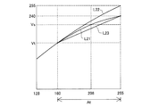
図5は、入力階調値が128以上の領域におけるトーンカーブを示す図である。ユーザは、ハイライトポイント・チェックボックス240(図2参照)をチェックすることで、トーンカーブにおいて入力階調値が255であるときの出力階調値を255ではなく240とすることができる。ハイライトポイント・チェックボックス240がチェックされた場合は、トーンカーブは、入力階調値が160以上の移行領域Atにおいて、なだらかに(255,240)の点に向かうように変形される。
FIG. 5 is a diagram showing a tone curve in an area where the input gradation value is 128 or more. By checking the highlight point check box 240 (see FIG. 2), the user can set the output tone value when the input tone value is 255 in the tone curve to 240 instead of 255. When the highlight
図5において、ハイライトポイント・チェックボックス240がチェックされたことによって、改変されたトーンカーブをトーンカーブL21とする。ハイライトポイント・チェックボックス240がチェックされる前のトーンカーブをトーンカーブL22とする。(160,Vt)と(255,240)を通る直線を直線L23とする。ここで、Vtは、入力階調値が160のときトーンカーブL22によって決まる出力階調値である。改変されたトーンカーブL21の形状は、たとえば、(160,Vt)と(255,240)と(208,Vs)を通る2次曲線とすることができる。ここで、Vsは、入力階調値が208のとき、トーンカーブL22で決定される出力階調値と、直線L23で決定される出力階調値と、の中間の階調値である。
In FIG. 5, the tone curve modified by checking the highlight
このように、画像データ中で最も明るい階調値についても、出力階調値を最大値としないようにすることで、以下のような効果が得られる。すなわち、画像データ中で最も明るい色が指定されている領域についても、印刷の際にインクが記録されるようにすることができる。その結果、最も明るい色が指定されている領域にインクが記録されず、インクが記録されている他の部分との間で印刷物の表面の質感が違ってしまう、という問題が生じなくなる。 As described above, the following effects can be obtained by setting the output gradation value not to the maximum value even for the brightest gradation value in the image data. That is, ink can be recorded at the time of printing even in a region where the brightest color is designated in the image data. As a result, there is no problem that ink is not recorded in the area where the brightest color is specified, and the texture of the surface of the printed material is different from other parts where ink is recorded.
また、印刷媒体上で画像のすべての領域についてインクが記録されるため、最も明るい色が指定されている領域が画像の端にある場合にも、どこまでが画像であり、どこからが画像でないかの区別がつきやすくなる。 Also, since ink is recorded for all areas of the image on the print medium, even if the area where the brightest color is specified is at the edge of the image, what is the image and where is not the image It becomes easy to distinguish.
以上のようにして、ユーザは、色調設定画面200の各要素を操作して、白黒画像の濃淡を改変するためのトーンカーブGdを決定する。色調設定画面200をCRT21の画面上に示し、ユーザからの指示を受け入れる機能を果たす機能部を、図1において、ユーザインターフェイス部98aとして示す。また、ユーザによって指定されたガンマ値に応じてトーンカーブを準備する機能を果たす機能部を、変換曲線準備部98bとして示す。そして、暗部トーン調整スケール236、明部トーン調整スケール238と、ハイライトポイント・チェックボックス240を介して入力されたユーザの指示に応じてトーンカーブを部分的に改変する機能を果たす機能部を、図1において、変換曲線改変部98cとして示す。
As described above, the user operates each element of the color
A3.印刷用1次元ルックアップテーブルの生成:
色変換モジュール98の機能部である印刷用変換テーブル生成部98d(図1参照)は、印刷用基準1次元ルックアップテーブル104dに基づいて、印刷用1次元ルックアップテーブル104cを生成する。印刷用1次元ルックアップテーブル104dは、白黒画像をデフォルトの色調で印刷する際に使用されるルックアップテーブルである。一方、印刷用1次元ルックアップテーブル104cは、色調設定画面200を介して決定されたトーンカーブGdに応じて白黒画像の濃淡の改変を行って印刷する際に使用されるルックアップテーブルである。
A3. Generate a one-dimensional lookup table for printing:
A printing conversion
図6は、印刷用1次元ルックアップテーブル104cの生成方法を示す説明図である。図6の上段に示すグラフの横軸は明度を表す階調値である。横軸上で右に行くほどグレーの明るさは明るくなり、左に行くほど暗くなる。初期画像データPID(図1参照)が、明度を表す0〜255の階調値で表されている白黒画像のデータであることから、横軸の入力階調値は0〜255である。 FIG. 6 is an explanatory diagram showing a method for generating the printing one-dimensional lookup table 104c. The horizontal axis of the graph shown in the upper part of FIG. 6 is a gradation value representing lightness. The gray becomes brighter as it goes to the right on the horizontal axis, and darker as it goes to the left. Since the initial image data PID (see FIG. 1) is black-and-white image data represented by gradation values from 0 to 255 representing lightness, the input gradation values on the horizontal axis are from 0 to 255.
一方、図6の上段に示すグラフの縦軸は、シアン、マゼンダ、イエロー、第1〜第3の無彩色インクの階調値である。横軸の入力階調値が0〜255であるのに対して、縦軸の出力階調値は、0〜65535である。印刷用基準1次元ルックアップテーブル104dにおけるシアン、マゼンダ、イエロー、第1〜第3の無彩色インクの階調値を、それぞれ破線のグラフC,M,Y,K1,K2,K3で示す。そして、印刷用1次元ルックアップテーブル104cにおけるシアン、マゼンダ、イエロー、第1〜第3の無彩色インクの階調値を、それぞれ実線のグラフCr,Mr,Yr,K1r,K2r,K3rで示す。 On the other hand, the vertical axis of the graph shown in the upper part of FIG. 6 represents the tone values of cyan, magenta, yellow, and first to third achromatic inks. The input gradation value on the horizontal axis is 0 to 255, while the output gradation value on the vertical axis is 0 to 65535. The gradation values of cyan, magenta, yellow, and first to third achromatic inks in the printing reference one-dimensional lookup table 104d are indicated by broken line graphs C, M, Y, K1, K2, and K3, respectively. The gradation values of cyan, magenta, yellow, and first to third achromatic inks in the printing one-dimensional lookup table 104c are indicated by solid line graphs Cr, Mr, Yr, K1r, K2r, and K3r, respectively.
印刷用変換テーブル生成部98dは、色調設定画面200を通じて設定されたトーンカーブに応じて、印刷用基準1次元ルックアップテーブル104dの第1〜第3の無彩色インク(K1〜K3)、およびシアン(C)、マゼンダ(M)、イエロー(Y)のインクのグラフを、それぞれ変形させる。そうすることによって、印刷用変換テーブル生成部98dは、印刷用1次元ルックアップテーブル104cの第1〜第3の無彩色インク(K1〜K3)とシアン(C)、マゼンダ(M)、イエロー(Y)のインクのグラフを生成する。
The printing conversion
図6の下段に示すグラフの横軸はグレーの入力階調値である。上段のグラフと同様、横軸上で右に行くほどグレーの明るさは明るくなり、左に行くほど暗くなる。図6の下段に示すグラフの縦軸は、決定されたトーンカーブGdに従った変換による各階調値の増分ΔVである。この変換は、矢印a1〜a3で示すように、0と255をのぞき、各入力階調値をより大きな値の出力階調値に変換している。よって、生成すべき印刷用1次元ルックアップテーブル104cは、白黒画像の同じ明度の階調値に対してより明るい色を出力するように、印刷用基準1次元ルックアップテーブル104dを改変して生成される。 The horizontal axis of the graph shown in the lower part of FIG. 6 is the gray input tone value. Similar to the upper graph, the gray becomes brighter as it goes to the right on the horizontal axis and darker as it goes to the left. The vertical axis of the graph shown in the lower part of FIG. 6 represents an increment ΔV of each gradation value by conversion according to the determined tone curve Gd. In this conversion, as indicated by arrows a1 to a3, each input gradation value is converted into a larger output gradation value except for 0 and 255. Therefore, the printing one-dimensional lookup table 104c to be generated is generated by modifying the printing reference one-dimensional lookup table 104d so that a brighter color is output with respect to the gradation value of the same brightness of the monochrome image. Is done.
たとえば、トーンカーブGdに従った変換によって、入力階調値128が出力階調値136に変換される場合を考える。この場合、印刷用1次元ルックアップテーブル104cは、印刷用基準1次元ルックアップテーブル104dにおいて階調値136に対して与えられていた出力階調値を、階調値128に対して与えるように変形される。この例では、印刷用1次元ルックアップテーブル104cは、図6の中段において矢印b1〜b3で示すように、印刷用基準1次元ルックアップテーブル104dに比べて、左方向にひずんだ形状となる。ただし、入力階調値0と255における出力階調値は変わらない。
For example, consider a case where the
図1の色変換モジュール98は、このようにして生成した印刷用1次元ルックアップテーブル104dに従って、白黒の画像データMID1を、第1〜第3の無彩色インク(K1〜K3)、とシアン(C)、マゼンダ(M)、イエロー(Y)のインクの階調値で各画素の色が表された画像データMID2に変換する。このような機能を果たす機能部を画像変換部98eとして示す。
The
一般に、白黒画像を印刷するのは、従来からの銀塩写真愛好家など、微妙な画質の調整を希望するユーザである。第1実施例は、以上で説明したような構成を有することにより、そのようなユーザに対して、白黒画像の画質の微妙な調整を可能とする。 In general, a monochrome image is printed by a user who desires a fine adjustment of image quality, such as a conventional silver salt photograph enthusiast. Since the first embodiment has the configuration described above, it is possible to finely adjust the image quality of a monochrome image for such a user.
A4.カラー画像の色変換:
図7は、プリンタドライバ96の色調設定画面202を示す説明図である。初期画像データPIDが、各画素の色がレッド、グリーン、ブルーの0〜255の階調値で表されているカラー画像のデータである場合の印刷について説明する。初期画像データPIDが、カラー画像のデータである場合にも、印刷の際には、プリンタドライバ96の色調設定画面が表示される。ただし、そのカラー画像用色調設定画面202には、暗部トーン調整スケール236と明部トーン調整スケール238とハイライトポイント・チェックボックス240とは設けられていない(図2参照)。また、画像に付す色調を指定するためのカラーサークル210と、画像に付す色調の設定をあらかじめ用意されたものの中から選択するためのカラートーン選択部250も、白黒画像のみに必要なものであるため、カラー画像用色調設定画面202には、設けられていない。他の点は、図2に示す、モノクロ画像用の色調設定画面200と同じである。
A4. Color image color conversion:
FIG. 7 is an explanatory diagram showing a color
カラー画像用色調設定画面202においても、白黒画像用の色調設定画面200と同様に、ユーザは、ガンマ値指定部、明度スケール、コントラストスケールを介してトーンカーブの形状を指定することができる(図2参照)。ただし、カラー画像用色調設定画面202においては、ユーザは、ガンマ値指定部を介して1.5、1.8、2.2の3個の候補値の中からガンマ値を選択することができる。これらは、候補ガンマ値格納部102(図1参照)内に格納されている。一方、暗部トーン調整スケール236と明部トーン調整スケール238は表示されていないため、暗部領域および明部領域の画素の色調を調整することはできない(図2および図4参照)。
Also in the color image
一般的なユーザは、滅多にモノクロ印刷は行わず、デジタルスチルカメラで生成したり、ホームページ上から取得したカラー画像をそのままカラー画像として印刷する。また、一般的なユーザは、煩雑な手続きは好まない。よって、上記のように、カラー画像用色調設定画面202に暗部トーン調整スケール236と明部トーン調整スケール238を表示せず、暗部領域および明部領域の色調の調整の必要性の有無を判断させないことで、ユーザに煩雑さを感じさせず簡潔な手続きでカラー画像の印刷を行わせることができる。
A general user rarely performs monochrome printing, and prints a color image generated by a digital still camera or acquired from a home page as a color image. Also, general users do not like complicated procedures. Therefore, as described above, the dark part
一方、白黒画像を印刷するのは、従来からの銀塩写真愛好家など、微妙な画質の調整を希望するユーザである。第1実施例は、モノクロ画像用の色調設定画面200において、暗部トーン調整スケール236と明部トーン調整スケール238を表示し、暗部領域および明部領域の色調の調整を可能としている。そうすることで、第1実施例のプリンタドライバは、白黒画像を印刷するユーザが白黒画像の画質の微妙な調整をすることを可能としている。
On the other hand, a monochrome image is printed by a user who desires a fine adjustment of image quality, such as a conventional silver salt photograph enthusiast. In the first embodiment, the dark
印刷用基準印刷用3次元ルックアップテーブル104b(図1参照)は、ユーザが画像データの画像をデフォルトの色調で印刷を行う場合に使用されるルックアップテーブルである。これに対して、印刷用3次元ルックアップテーブル104aは、ユーザが画像データの画像の色調を変化させて印刷を行う場合に使用されるルックアップテーブルである。印刷用3次元ルックアップテーブル104aは、印刷用基準印刷用3次元ルックアップテーブル104bから生成される。 The reference printing three-dimensional lookup table 104b (see FIG. 1) is a lookup table used when a user prints an image of image data with a default color tone. On the other hand, the printing three-dimensional lookup table 104a is a lookup table used when the user performs printing by changing the color tone of the image of the image data. The printing three-dimensional lookup table 104a is generated from the printing reference printing three-dimensional lookup table 104b.
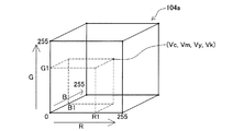
図8は、印刷用基準印刷用3次元ルックアップテーブル104bを示す図である。印刷用基準印刷用3次元ルックアップテーブル104bは、レッド、グリーン、ブルーの3個の階調値の組み合わせ(Vr,Vg,Vb)と、シアン、マゼンダ、イエロー、第1〜第3の無彩色インクの階調値の組み合わせ(Vc,Vm,Vy,Vk,Vlk,Vllk)とを、対応づけて格納しているテーブルである。 FIG. 8 is a diagram showing the reference printing three-dimensional lookup table 104b. The reference printing three-dimensional lookup table 104b includes a combination of three gradation values of red, green, and blue (Vr, Vg, Vb), cyan, magenta, yellow, and first to third achromatic colors. It is a table that stores combinations of ink gradation values (Vc, Vm, Vy, Vk, Vlk, Vllk) in association with each other.
初期画像データPIDが、カラー画像データである場合、そのカラー画像データは、各画素の色が、それぞれ0〜255の値をとるレッド、グリーン、ブルーの3個の階調値の組み合わせで表された画像データである。よって、印刷用基準印刷用3次元ルックアップテーブル104bのレッド、グリーン、ブルーの3個の入力階調値Vr,Vg,Vbも、それぞれ0〜255の値をとる。また、印刷用基準印刷用3次元ルックアップテーブル104bにおいては、出力階調値であるシアン、マゼンダ、イエロー、第1〜第3の無彩色インクの階調値Vc,Vm,Vy,Vk,Vlk,Vllkも0〜255の値をとる。 When the initial image data PID is color image data, the color image data is represented by a combination of three gradation values of red, green, and blue in which the color of each pixel takes a value of 0 to 255, respectively. Image data. Accordingly, the three input gradation values Vr, Vg, and Vb of red, green, and blue in the reference printing three-dimensional lookup table 104b also take values of 0 to 255, respectively. In the reference printing three-dimensional lookup table 104b, the gradation values Vc, Vm, Vy, Vk, and Vlk of the output gradation values of cyan, magenta, yellow, and first to third achromatic inks are used. , Vllk also takes values from 0 to 255.
ガンマ値指定部、明度スケール、コントラストスケールを介してトーンカーブの形状が決定されると、色変換モジュール98の印刷用変換テーブル生成部98d(図1参照)は、印刷用基準1次元ルックアップテーブル104dから印刷用1次元ルックアップテーブル104cを生成したときと同様に、印刷用3次元ルックアップテーブル104aを生成する。すなわち、トーンカーブの形状に基づいて印刷用基準印刷用3次元ルックアップテーブル104bを改変して、印刷用3次元ルックアップテーブル104aを生成する。ただし、その際の変換作業は、レッド、グリーン、ブルーの各階調値について行う必要がある。
When the shape of the tone curve is determined via the gamma value designation unit, the brightness scale, and the contrast scale, the printing conversion
画像変換部98eは、このようにして生成した印刷用3次元ルックアップテーブル104aに従って、カラーの画像データMID1を、シアン、マゼンダ、イエロー、第1〜第3の無彩色インクの6色の階調値で各画素の色が表された画像データMID2に変換する。 The image conversion unit 98e converts the color image data MID1 into six gradations of cyan, magenta, yellow, and first to third achromatic inks in accordance with the three-dimensional printing look-up table 104a thus generated. The value is converted into image data MID2 in which the color of each pixel is represented.
なお、印刷用基準1次元ルックアップテーブル104dおよび印刷用1次元ルックアップテーブル104cの出力階調値が、0〜65535の値をとりうるのに対して、印刷用基準印刷用3次元ルックアップテーブル104bおよび印刷用3次元ルックアップテーブル104aは、より少ない0〜255の階調値しか取りえない。しかし、カラー画像においては、明度に加えて彩度、色相も表現される。よって、印刷用基準印刷用3次元ルックアップテーブル104bまたは印刷用3次元ルックアップテーブル104aで生成したカラー画像の印刷結果において、印刷対象の識別のしやすさが白黒画像の印刷結果に比べて大きく劣るわけではない。 The output gradation values of the printing reference one-dimensional lookup table 104d and the printing one-dimensional lookup table 104c can take values from 0 to 65535, whereas the printing reference printing three-dimensional lookup table. 104b and the printing three-dimensional lookup table 104a can take a smaller number of gradation values from 0 to 255. However, in a color image, saturation and hue are expressed in addition to lightness. Therefore, in the printing result of the color image generated by the printing reference printing three-dimensional lookup table 104b or the printing three-dimensional lookup table 104a, the identification of the printing target is easier than the printing result of the monochrome image. Not inferior.
一方、第1実施例は、白黒画像を印刷する場合には、カラー画像を印刷する場合に比べて多数の階調で表現された画像データMID2を出力する。そして、その後のハーフトーン処理も、その多数の階調に基づいて実行される。このため、第1実施例によれば、白黒画像の印刷において、微妙な濃淡を表現することができる。よって、白黒印刷の印刷を好む従来からの銀塩写真愛好家の期待に応えることができる。また、彩度、色相を有しない白黒画像において、暗い部分や明るい部分にある印刷対象が識別しやすいように、印刷を行うことができる。 On the other hand, in the first embodiment, when printing a black and white image, the image data MID2 expressed by a larger number of gradations is output than when a color image is printed. Then, the subsequent halftone process is also executed based on the large number of gradations. For this reason, according to the first embodiment, it is possible to express subtle shades in printing a monochrome image. Therefore, it can meet the expectations of conventional silver salt photography enthusiasts who prefer black and white printing. Further, in a black and white image having no saturation and hue, printing can be performed so that a print target in a dark part or a bright part can be easily identified.
このように、第1実施例の印刷システムは、カラー画像を印刷するユーザと、白黒画像を印刷するユーザとのそれぞれの嗜好に応じて、適切な印刷環境を提供することができる。また、ルックアップテーブルを改変することで画像データの色調の改変を実現しているため、大きな画像データを処理する場合にも、迅速な処理ができる。すなわち、画像データの大きさによって、必要とする処理時間が大幅に拡大することがない。 As described above, the printing system according to the first embodiment can provide an appropriate printing environment according to each preference of a user who prints a color image and a user who prints a monochrome image. Further, since the color tone of the image data is changed by changing the look-up table, quick processing can be performed even when processing large image data. That is, the required processing time does not significantly increase depending on the size of the image data.
B.第2実施例
白黒画像に、セピア調などの所定の色調を付して印刷を実行する場合がある。第2実施例ではそのような場合について説明する。第2実施例においては、1次元ルックアップテーブルおよびその生成方法が第1実施例とは異なっている。他の点は第1実施例と同じである。
B. Second Embodiment Printing may be executed with a predetermined color tone such as a sepia tone applied to a black and white image. In the second embodiment, such a case will be described. In the second embodiment, the one-dimensional lookup table and its generation method are different from those in the first embodiment. Other points are the same as the first embodiment.
色調設定画面200のカラーサークル210(図2参照)は、L*a*b*表色系において、L*が55であるa*b*平面であり、かつ、a*=b*=0を中心点Oとする半径20の円に含まれる部分である。すなわち、カラーサークル210は、グレーの点を中心に有し、カラーサークル210内の位置に応じてa*、b*の少なくともいずれか一つが段階的に異なっている円盤である。ユーザは、マウス130を介してカラーサークル210内の一点を指定することで、白黒画像に付す色調を指定することができる。
The color circle 210 (see FIG. 2) of the color
また、ユーザは、カラートーン選択部250(図2参照)を操作して、画像に付す色調を規定するパラメータの設定をあらかじめ用意されたものの中から選択することもできる。あらかじめ用意するパラメータの設定としては、寒色気味の色調であるクール調、暖色気味の色調であるウォーム調、写真が褪色した色合いであるセピア調などとすることができる。 In addition, the user can operate the color tone selection unit 250 (see FIG. 2) to select a parameter setting that defines the color tone to be added to the image from those prepared in advance. As the parameter settings prepared in advance, a cool tone that is a cool color tone, a warm tone that is a warm color tone, a sepia tone that is a faded color of a photograph, and the like can be used.
図9は、第2実施例において、カラーサークル210により指定されたパラメータを使って色調を変化させたトーン調整用1次元ルックアップテーブル104eおよび印刷用基準1次元ルックアップテーブル104dを示す説明図である。図9においては、印刷用基準1次元ルックアップテーブル104dにおける各インク色の階調値を破線のグラフC,M,Y,K1,K2,K3で示す。そして、トーン調整用1次元ルックアップテーブル104eにおける各インクの階調値を、実線のグラフCr,Mr,Yr,K1r,K2r,K3rで示す。なお、トーン調整用1次元ルックアップテーブル104eの生成の際には、第1〜第3の無彩色インクのグラフは改変されない。よって、K1とK1r,K2とK2r,K3とK3rのグラフは重なっている。
FIG. 9 is an explanatory diagram showing a tone adjustment one-dimensional lookup table 104e and a printing reference one-dimensional lookup table 104d in which the color tone is changed using parameters specified by the
ユーザによって、カラーサークル210またはカラートーン選択部250を介して白黒画像に付する色調が指定されると、まず、トーン調整用1次元ルックアップテーブル104eが生成される。具体的には、ユーザが指定した色調に応じてシアン(C)、マゼンタ(M)、イエロ(Y)の出力階調値の情報が生成され、印刷用基準1次元ルックアップテーブル104fのシアン(C)、マゼンタ(M)、イエロ(Y)の出力階調値に修正が加えられて、トーン調整用1次元ルックアップテーブル104eが生成される。たとえば、セピア調の色調が付与される場合には、図9に示すように、シアンの階調値が全体に下げられ、マゼンタとイエローの階調値が全体に上げられる。これら各色の出力階調値は、第1実施例の印刷用1次元ルックアップテーブル104cと同様、0〜65535である。
When the user designates a color tone to be added to a black and white image via the
その後、色調設定画面200を介して決定されたトーンカーブGd(図4(a)参照)に基づいて、上記のトーン調整用1次元ルックアップテーブル104eがさらに改変されて、印刷用1次元ルックアップテーブル104cが生成される(図6参照)。改変の仕方は第1実施例において、印刷用基準1次元ルックアップテーブル104dから印刷用1次元ルックアップテーブル104cを生成した際の方法と同じである。
Thereafter, based on the tone curve Gd (see FIG. 4A) determined via the color
このような態様とすれば、寒色気味の色調であるクール調、暖色気味の色調であるウォーム調、写真が褪色した色合いであるセピア調その他の、所定の色調が付された白黒画像を印刷する際にも、微妙な色の調整を行うことができる。 According to such an aspect, a black and white image with a predetermined color tone is printed, such as a cool tone that is a cool color tone, a warm tone that is a warm color tone, a sepia tone that is a faded color of a photograph, and the like. Sometimes, fine color adjustments can be made.
なお、本明細書において、「モノクロ画像データ」は、画像を構成する各画素について明度のみの情報を有する画像データであってもよいし、クール調、ウォーム調、セピア調などの所定の色調を有する画像であってもよい。すなわち、モノクロ画像データは、互いに明度が異なる複数の色の集合である一系列の階調値で、画素の色が表現された画像データであればよい。第1および第2実施例におけるモノクロ画像用の印刷処理は、初期画像データPIDから、各画素について明度のみの情報を有する白黒画像のデータMID2を生成して印刷する場合と、各画素の色が上記のような一系列の階調値で表されているデータMID2を生成して印刷する場合と、のいずれにも対応するものである。 In this specification, the “monochrome image data” may be image data having only lightness information for each pixel constituting the image, or a predetermined color tone such as cool tone, warm tone, sepia tone, or the like. It may be an image. That is, the monochrome image data may be image data in which the color of a pixel is expressed by a series of gradation values that are a set of a plurality of colors having different brightness values. In the printing process for a monochrome image in the first and second embodiments, when the monochrome image data MID2 having only brightness information is generated from the initial image data PID and printed, and the color of each pixel is This corresponds to both the case where the data MID2 represented by a series of gradation values as described above is generated and printed.
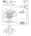
C.第3実施例
図10は、第3実施例の印刷システムのソフトウェアの構成を示すブロック図である。第1実施例においては、プリンタドライバ96がトーンカーブに応じて印刷用ルックアップテーブル104c,104aを生成することで、画像データの色の調整を実現していた。しかし、第3実施例では、アプリケーション95tが、原画像データORGの画素の階調値を改変することで画像データの色を改変する。第3実施例においては、プリンタドライバ96tは、色変換テーブル104として、印刷用基準印刷用3次元ルックアップテーブル104bのみを備える。そして、プリンタドライバ96tは、アプリケーション95tから受け取った初期画像データPIDをそのままの色調で印刷画像データFNLに変換する。第3実施例の他の点は、第1実施例と同じである。
C. Third Embodiment FIG. 10 is a block diagram illustrating a software configuration of a printing system according to a third embodiment. In the first embodiment, the
第3実施例においては、アプリケーション95tは、ユーザインターフェイス部95a、変換曲線準備部95b、変換曲線改変部95c、画像変換部95fを備える。ユーザインターフェイス部95a、変換曲線準備部95b、変換曲線改変部95cは、それぞれ第1実施例におけるユーザインターフェイス部98a、変換曲線準備部98b、変換曲線改変部98cと同様の機能を果たす。
In the third embodiment, the application 95t includes a user interface unit 95a, a conversion
画像変換部95fは、ユーザによって決定されたトーンカーブGdに応じて原画像データORGの各画素の階調値を変換する。そして、アプリケーション95tは、変換後の画像データを初期画像データPIDとしてプリンタドライバ96tに出力する。プリンタドライバ96tは、アプリケーション95tから受け取った初期画像データPIDを、印刷用基準印刷用3次元ルックアップテーブル104bを参照しつつ、そのままの色調で印刷画像データFNLに変換する。
The image conversion unit 95f converts the gradation value of each pixel of the original image data ORG according to the tone curve Gd determined by the user. Then, the application 95t outputs the converted image data to the
第3実施例のような態様とすれば、印刷の際にルックアップテーブルを生成する必要がない。このため、ユーザがアプリケーション95tに印刷を指示してから、短時間で印刷を開始することができる。 With an aspect like the third embodiment, it is not necessary to generate a lookup table at the time of printing. Therefore, printing can be started in a short time after the user instructs printing to the application 95t.
D.変形例.
なお、この発明は上記の実施例や実施形態に限られるものではなく、その要旨を逸脱しない範囲において種々の態様において実施することが可能であり、例えば次のような変形も可能である。
D. Modified example.
The present invention is not limited to the above-described examples and embodiments, and can be implemented in various modes without departing from the gist thereof. For example, the following modifications are possible.
D1.変形例1
図11は、パラメータに対応したコントラスト変換用のトーンカーブを示す図である。第1実施例では、白黒画像の印刷においては、カラー画像の印刷よりも多数のガンマ値の候補が用意されており、ガンマ値に応じた多数のトーンカーブが選択可能であった。しかし、予め用意されるトーンカーブは、ガンマ変換を表すものだけではなく、他の変換を表すトーンカーブであってもよい。たとえば、図11に示すように、コントラスト変換用のトーンカーブC1〜C6を用意し、それぞれのカーブにパラメータを対応づけてもよい。そして、白黒画像の印刷に際しては、カラー画像の印刷の場合よりも多数のトーンカーブ(パラメータ)を選択できるようにしてもよい。なお、図11において、トーンカーブC0,C4〜C6は直線である。そして、トーンカーブC0は、コントラストを改変しない場合のトーンカーブである。
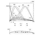
D1. Modification 1
FIG. 11 is a diagram showing a tone curve for contrast conversion corresponding to a parameter. In the first embodiment, in printing a monochrome image, more gamma value candidates are prepared than in printing a color image, and a large number of tone curves corresponding to the gamma value can be selected. However, the tone curve prepared in advance is not limited to the one representing gamma conversion, but may be a tone curve representing another conversion. For example, as shown in FIG. 11, tone curves C1 to C6 for contrast conversion may be prepared, and parameters may be associated with the respective curves. When printing a monochrome image, more tone curves (parameters) may be selected than when printing a color image. In FIG. 11, tone curves C0 and C4 to C6 are straight lines. The tone curve C0 is a tone curve when the contrast is not altered.
なお、各パラメータおよびトーンカーブは、白黒画像にも適用でき、カラー画像にも適用できるものがあってもよい。また、トーンカーブが表す階調値変換は、互いに異なる明度を有する階調値からなる所定の階調値系列の階調値を、同じ階調値系列の同一の階調値、または異なる階調値に変換する階調値変換であることが好ましい。たとえば、階調値変換は、セピア色調のモノクロの階調値0〜255のうちのいずれかの階調値を、同じセピア調のモノクロの階調値の他の階調値に変換するものとすることができる。たとえば、モノクロの階調値0〜255のうち208〜255の階調値のみを改変する階調値変換とすることができる。寒色調、暖色調、無彩色(グレー)のモノクロの階調値についても同様である。また、各パラメータは、数字に限らず、アルファベットでもよいし他の文字や記号であってもよい。すなわち、互いに異なる色変換に対応する符号であれば、どのようなものでもよい。
Each parameter and tone curve can be applied to a black and white image, and some can be applied to a color image. In addition, the tone value conversion represented by the tone curve is performed by changing the tone value of a predetermined tone value series composed of tone values having different brightness values, the same tone value of the same tone value series, or different tone values. It is preferable that the gradation value conversion is performed to convert the value. For example, the gradation value conversion is performed by converting any one of the gradation values 0 to 255 in sepia tone monochrome into another gradation value in the same sepia tone monochrome gradation value. can do. For example, it is possible to perform gradation value conversion that modifies only the gradation values 208 to 255 out of the
D2.変形例2
第1実施例においては、色調設定画面200に、画像データにおける最も明るい色の明るさを調整するためのハイライトポイント・チェックボックス240が設けられていた。しかし、画像データにおける最も明るい色の明るさを調整するための手段としては、明度スケール232等と同様のスケールとしてもよい。たとえば、右端から左に向かって操作するスケールを色調設定画面に表示し、左に行くほど画像データにおける最も明るい色の明るさが暗くなることとしてもよい。
D2. Modification 2
In the first embodiment, the color
なお、第1実施例においては、画像データにおける最も明るい色の階調値は、ハイライトポイント・チェックボックス240にチェックが入ることによって240となったが、最も明るい色の階調値は他の値であってもよい。すなわち、調整によって設定される最も明るい色の階調値は、出力階調値の最大値よりも小さい任意の値とすることができる。
In the first embodiment, the tone value of the brightest color in the image data is 240 when the highlight
D3.変形例3
図12は、画像データにおける最も暗い色の明るさを調整した場合のトーンカーブを示す図である。色調設定画面には、画像データにおける最も暗い色の明るさを調整するためのシャドウポイント・チェックボックスを設けてもよい。このチェックボックスにチェックを入れることで、たとえば、画像データにおける最も暗い色の階調値が0ではなく、より大きな値、たとえば80や192となるようにすることもできる。このような態様とすれば、全体に明るい画像を得ることができ、ポスターの背景などに使用する際に好適である。
D3. Modification 3
FIG. 12 is a diagram illustrating a tone curve when the brightness of the darkest color in the image data is adjusted. The color tone setting screen may be provided with a shadow point check box for adjusting the brightness of the darkest color in the image data. By checking this check box, for example, the gradation value of the darkest color in the image data can be set to a larger value, for example, 80 or 192, instead of 0. With such an aspect, a bright image can be obtained as a whole, which is suitable for use in a poster background or the like.
なお、画像データにおける最も暗い色の明るさを調整するための手段が、チェックボックスではなく、スケールであってもよいことは、最も明るい色の明るさを調整するための手段と同様である。また、最も暗い色の階調値は、出力階調値の最小値よりも大きい任意の値とすることができる。 Note that the means for adjusting the brightness of the darkest color in the image data may be a scale instead of a check box, similar to the means for adjusting the brightness of the brightest color. Further, the gradation value of the darkest color can be an arbitrary value larger than the minimum value of the output gradation value.
また、画像データにおいて最も暗い色の階調値は、印刷媒体の種類に応じて決定してもよい。たとえば、表面の凹凸の少ない光沢紙の場合には、比較的低く設定し、表面の凹凸の多いマット紙の場合には、それよりも高く設定することも好ましい。マット紙の場合には、光沢紙に比べて階調値0近辺の非常に暗い色を再現しにくいためである。同様に、画像データにおいて最も明るい色の階調値を、印刷媒体の種類に応じて決定してもよい。なお、印刷媒体の種類は、プリンタドライバ96のユーザインターフェイス画面を通じてユーザに入力させることとしてもよいし、プリンタが自動的に認識して、印刷媒体の種類の情報をプリンタドライバ96に送信することとしてもよい。
Further, the tone value of the darkest color in the image data may be determined according to the type of print medium. For example, it is also preferable to set a relatively low value in the case of glossy paper with few surface irregularities, and to set it higher in the case of matte paper with many surface irregularities. This is because, in the case of mat paper, it is difficult to reproduce a very dark color near the
なお、「印刷媒体の種類」とは、インクを記録していない領域と、同じインクで塗りつぶした領域と、の明度に応じて決定される種類とすることができる。その場合、2種類の印刷媒体について、インクを記録していない領域と、同じインクで塗りつぶした領域と、をそれぞれ側色計で計測し、L*a*b*表色系のL*が、いずれかについて10%以上異なる場合には、「種類が異なる印刷媒体」であるとする。 The “type of printing medium” can be a type determined according to the brightness of an area where ink is not recorded and an area painted with the same ink. In that case, for the two types of print media, the area where ink is not recorded and the area painted with the same ink are each measured with a side colorimeter, and L * a * b * L * of the color system is If any of them differs by 10% or more, it is assumed that the print media are “different types”.
D4.変形例4
第1実施例においては、印刷用基準1次元ルックアップテーブル104d(図1参照)は、階調値が小さい暗部領域Asにおいて、色をL*a*b*表色系で表したときに、色のL*の値が、色を表す入力階調値の増加に対して線形に増加する部分を含む階調特性を有することができる。そのような階調特性とすれば、暗部領域Asにおいて、画像に記録されている対象が識別しやすいようになる。また、そのような特性を暗部領域におけるデフォルトの階調特性とし、ユーザが、それを暗部トーン調整スケール236で改変することができるようにすることも好ましい。
D4. Modification 4
In the first embodiment, the printing reference one-dimensional look-up table 104d (see FIG. 1) indicates that when the color is expressed in the L * a * b * color system in the dark area As having a small gradation value, The color L * value may have a gradation characteristic including a portion that increases linearly with an increase in the input gradation value representing the color. With such gradation characteristics, it becomes easy to identify the target recorded in the image in the dark area As. It is also preferable that such characteristics be the default gradation characteristics in the dark area, and that the user can modify it with the dark area
また、ユーザが指定する部分トーンカーブは、2次曲線であった。しかし、ユーザが指定する部分トーンカーブは、2次曲線に限らず、他の曲線とすることもできる。たとえば、3次曲線であってもよいし、4次曲線、スプライン曲線、ベジエ曲線などでもよい。ただし、ユーザが指定する部分トーンカーブとして、3次曲線、4次曲線などを使用する場合は、曲線が通る点として複数の点を指定させることが好ましい。 The partial tone curve specified by the user was a quadratic curve. However, the partial tone curve specified by the user is not limited to the quadratic curve, but may be another curve. For example, it may be a cubic curve, a quartic curve, a spline curve, a Bezier curve, or the like. However, when a cubic curve, a quartic curve, or the like is used as the partial tone curve designated by the user, it is preferable to designate a plurality of points as points through which the curve passes.
また、部分トーンカーブGsの一部、たとえば階調値0〜32の暗部領域Asのうち、上から1/4の接続領域Asc(図4(b)参照)にある部分については、元の部分トーンカーブの形状から大きく変化しないようにトーンカーブを変形することも好ましい。具体的には、接続領域Ascのトーンカーブの形状は、各入力階調値に対する出力階調値の値が、元のトーンカーブによって決まる出力階調値と、ユーザによって指定された2次曲線やスプライン曲線等の曲線によって決まる出力階調値と、の間の重み付け平均値となるように決定される。接続領域Ascの上限(入力階調値32)においては、元のトーンカーブの重みが100%である。そして、接続領域Ascの下限(入力階調値24)においては、指定された曲線の重みが100%である。重みは、入力階調値が低い方から高い方に向けて、元のトーンカーブの重みが大きくなるように変化する。
Further, a part of the partial tone curve Gs, for example, a part in the connection area Asc (see FIG. 4B) from the top in the dark part area As of the
同様に、明部領域Ahのうち、下から1/4の接続領域Ahc(図4(c)参照)については、元の部分トーンカーブの形状から大きく変化しないように、元の曲線と、ユーザの指定に基づいて暫定的に決定される曲線(2次曲線やスプライン曲線など)と、の重み付け平均を利用して曲線の形状を決定することも好ましい。 Similarly, in the bright area Ah, the connection area Ahc (see FIG. 4C) which is ¼ from the bottom, the original curve and the user so as not to change greatly from the shape of the original partial tone curve. It is also preferable to determine the shape of the curve using a weighted average of a curve (such as a quadratic curve or a spline curve) tentatively determined based on the designation of.
さらに、最も明るい色の明るさを調整する際のトーンカーブL21(図5参照)の形状も、第1実施例において示した方法のほか、上記と同様の方法で決定することができる。すなわち、トーンカーブL21の形状は、具体的には、各入力階調値に対する出力階調値の値が、トーンカーブL22によって決まる出力階調値と、直線L23によって決まる出力階調値と、の間の重み付け平均値となるように決定することができる。移行領域Atの下限(入力階調値160)において、トーンカーブL22の重みが100%とする。そして、移行領域Atの上限(入力階調値255)において、直線L23の重みが100%とする。重みは、入力階調値が高い方から低い方に向けて、トーンカーブL22の重みが大きくなるように変化する。 Furthermore, the shape of the tone curve L21 (see FIG. 5) when adjusting the brightness of the brightest color can be determined by the same method as described above in addition to the method shown in the first embodiment. In other words, the shape of the tone curve L21 is, specifically, an output tone value corresponding to each input tone value, an output tone value determined by the tone curve L22, and an output tone value determined by the straight line L23. It can be determined to be a weighted average value. At the lower limit of the transition area At (input gradation value 160), the weight of the tone curve L22 is assumed to be 100%. In the upper limit of the transition area At (input gradation value 255), the weight of the straight line L23 is 100%. The weight changes so that the weight of the tone curve L22 increases from the higher input gradation value toward the lower value.
D5.変形例5
第1実施例においては、部分的にトーンカーブの形状が改変される暗部領域Asは、入力階調値が0〜32の領域であった。しかし、部分的にトーンカーブの形状を改変する領域は、他の範囲とすることもできる。たとえば、0〜64であってもよい。ただし、入力階調値がとりうる値の範囲のうち下から20%までの範囲に含まれる領域であることが好ましく、下から12.5%までの範囲に含まれる領域であることがさらに好ましい。
D5. Modification 5
In the first embodiment, the dark part region As in which the shape of the tone curve is partially modified is a region having an input gradation value of 0 to 32. However, the region in which the shape of the tone curve is partially modified can be set to another range. For example, it may be 0-64. However, it is preferably a region included in the range from the bottom to 20% of the range of values that the input gradation value can take, and more preferably a region included in the range from the bottom to 12.5%. .
また、第1実施例においては、部分的にトーンカーブの形状が改変される明部領域Ahは、入力階調値が192〜255の領域であった。しかし、部分的にトーンカーブの形状を改変する領域は、他の範囲とすることもできる。たとえば、160〜255であってもよい。また、部分的にトーンカーブの形状が改変される領域は、階調値がとりうる範囲のうち中央の値(第1実施例において126)を含み、両端の値(第1実施例において0と255)を含まない所定の範囲であってもよい。ただし、入力階調値がとりうる値の範囲のうち上から40%までの範囲に含まれる領域であることが好ましく、上から25%までの範囲に含まれる領域であることがさらに好ましい。 In the first embodiment, the bright area Ah in which the shape of the tone curve is partially modified is an area having an input gradation value of 192 to 255. However, the region in which the shape of the tone curve is partially modified can be set to another range. For example, it may be 160 to 255. The region where the shape of the tone curve is partially modified includes the center value (126 in the first embodiment) of the range of gradation values, and the values at both ends (0 in the first embodiment). The predetermined range may not include 255). However, it is preferably a region included in the range from the top to 40% of the range of values that the input gradation value can take, and more preferably a region included in the range from the top to 25%.
D6.変形例6
第1実施例においては、暗部領域Asと明部領域Ahのトーンカーブの変形は、最も出力階調値が変化する点の明度の変化がプラスマイナス10の範囲内となるように行われた(図4参照)。しかし、トーンカーブの変形は、より広い範囲で行われてもよく、また、より狭い範囲に限定して行われてもよい。また、トーンカーブの変形幅は、印刷媒体の種類に応じて決定してもよい。たとえば、全体的な階調変化が大きい紙(広い範囲の階調を再現できる紙)では、比較的広く設定し、それよりも再現できる階調範囲が狭い場合には、それよりも狭く設定することも好ましい。
D6. Modification 6
In the first embodiment, the tone curves of the dark area As and the bright area Ah are deformed so that the change in brightness at the point where the output gradation value changes most is within the range of plus or minus 10 ( (See FIG. 4). However, the deformation of the tone curve may be performed in a wider range or may be performed limited to a narrower range. The deformation width of the tone curve may be determined according to the type of print medium. For example, on paper with a large overall gradation change (paper that can reproduce a wide range of gradations), set it relatively wide, and if the gradation range that can be reproduced is narrower, set it narrower than that. It is also preferable.
D7.変形例7
第1実施例においては、カラー印刷を行う場合には、ユーザは、トーンカーブに対応するパラメータであるガンマ値を3個の候補値の中から選択した。そして、モノクロ印刷を行う場合には、ユーザは、ガンマ値を6個の候補値の中から選択した。しかし、選択するパラメータの数はこれら限られず、他の数とすることもできる。すなわち、モノクロ印刷を行う場合に選択できるパラメータの数が、カラー印刷を行う場合に選択できるパラメータの数よりも多ければよい。ただし、モノクロ印刷を行う場合に選択できるパラメータの数が、カラー印刷を行う場合に選択できるパラメータの数の倍以上であることが好ましい。
D7. Modification 7
In the first embodiment, when color printing is performed, the user selects a gamma value that is a parameter corresponding to a tone curve from among three candidate values. When performing monochrome printing, the user selects a gamma value from six candidate values. However, the number of parameters to be selected is not limited to these, and may be other numbers. That is, the number of parameters that can be selected when performing monochrome printing should be larger than the number of parameters that can be selected when performing color printing. However, the number of parameters that can be selected when performing monochrome printing is preferably at least twice the number of parameters that can be selected when performing color printing.
D8.変形例8
第1実施例および第2実施例においては、モノクロ印刷において使用される印刷用1次元ルックアップテーブルの出力階調値は0〜65535(16bit)であり、カラー印刷において使用される印刷用3次元ルックアップテーブルの出力階調値は0〜255(8bit)であった。しかし、出力階調値の幅はこれらの数値に限られず、他の範囲とすることもできる。ただし、モノクロ印刷において使用されるルックアップテーブルの出力階調値がとりうる値の幅が、カラー印刷において使用されるルックアップテーブルの出力階調値がとりうる値の幅よりも広いことが好ましい。
D8. Modification 8
In the first and second embodiments, the output gradation value of the printing one-dimensional lookup table used in monochrome printing is 0 to 65535 (16 bits), and the printing three-dimensional printing used in color printing. The output gradation value of the lookup table was 0 to 255 (8 bits). However, the width of the output gradation value is not limited to these numerical values, and can be set to other ranges. However, it is preferable that the range of values that the output gradation values of the lookup table used in monochrome printing can take is wider than the range of values that the output gradation values of the lookup table used in color printing can take. .
D9.変形例9
上述した各実施形態では、有彩色インクとしてC,M,Yの3種類のインクを用いていたが、他の色を使用することもできる。たとえば、レッドやグリーン、パープルなどの有彩色インクや、ライトシアン、ライトマゼンタ、ダークイエロなどの同色系の濃淡有彩色インクを用いることも可能である。
D9. Modification 9
In each of the above-described embodiments, three types of inks C, M, and Y are used as the chromatic color ink. However, other colors can be used. For example, chromatic inks such as red, green, and purple, and light and dark chromatic inks of the same color such as light cyan, light magenta, and dark yellow can be used.
また、第1実施例、第2実施例においては、モノクロ印刷において使用される印刷用1次元ルックアップテーブルは、第1〜第3の無彩色インクおよびシアン、マゼンタ、イエロからなる表色系の出力階調値を有していた。しかし、モノクロ印刷において使用される印刷用1次元ルックアップテーブルは、他の色であってプリンタで使用されるインク色の出力階調値を含んでいてもよい。また、ブラック一色のみの出力階調値を有していてもよい。 In the first embodiment and the second embodiment, the printing one-dimensional lookup table used in monochrome printing is a color system composed of first to third achromatic inks, cyan, magenta, and yellow. It had an output tone value. However, the printing one-dimensional look-up table used in monochrome printing may include output tone values of ink colors that are other colors and are used in the printer. Further, it may have an output gradation value of only one black color.
D10.変形例10
第1実施例、第2実施例においては、カラー、モノクロ印刷において、変換曲線に応じて印刷用基準ルックアップテーブルを変換し、印刷用ルックアップテーブルを生成する。しかし、画像変換に使用されるハードウェアの処理能力が許容する場合、変換曲線を使って、直接入力画像データを変換することもできる。
D10. Modification 10
In the first and second embodiments, in color and monochrome printing, the printing reference lookup table is converted in accordance with the conversion curve to generate the printing lookup table. However, if the processing capability of the hardware used for image conversion allows, the input image data can be directly converted using a conversion curve.
D11.変形例11
上記実施例において、ハードウェアによって実現されていた構成の一部をソフトウェアに置き換えるようにしてもよく、逆に、ソフトウェアによって実現されていた構成の一部をハードウェアに置き換えるようにしてもよい。例えば、プリンタドライバ96(図1参照)の機能の一部をプリンタのCPU41が実行するようにすることもできる。また、上記実施例において、ドライバによって実現されていた構成の一部をアプリケーションソフトに置き換えるようにしてもよく、逆に、アプリケーションソフトによって実現されていた構成の一部をドライバに置き換えるようにしてもよい。
D11. Modification 11
In the above embodiment, a part of the configuration realized by hardware may be replaced by software, and conversely, a part of the configuration realized by software may be replaced by hardware. For example, a part of the functions of the printer driver 96 (see FIG. 1) can be executed by the
このような機能を実現するコンピュータプログラムは、フロッピディスクやCD−ROM等の、コンピュータ読み取り可能な記録媒体に記録された形態で提供される。ホストコンピュータは、その記録媒体からコンピュータプログラムを読み取って内部記憶装置または外部記憶装置に転送する。あるいは、通信経路を介してプログラム供給装置からホストコンピュータにコンピュータプログラムを供給するようにしてもよい。コンピュータプログラムの機能を実現する時には、内部記憶装置に格納されたコンピュータプログラムがホストコンピュータのマイクロプロセッサによって実行される。また、記録媒体に記録されたコンピュータプログラムをホストコンピュータが直接実行するようにしてもよい。 A computer program for realizing such a function is provided in a form recorded on a computer-readable recording medium such as a floppy disk or a CD-ROM. The host computer reads the computer program from the recording medium and transfers it to the internal storage device or the external storage device. Alternatively, the computer program may be supplied from the program supply device to the host computer via a communication path. When realizing the function of the computer program, the computer program stored in the internal storage device is executed by the microprocessor of the host computer. Further, the host computer may directly execute the computer program recorded on the recording medium.
この明細書において、コンピュータとは、ハードウェア装置とオペレーションシステムとを含む概念であり、オペレーションシステムの制御の下で動作するハードウェア装置を意味している。コンピュータプログラムは、このようなコンピュータに、上述の各部の機能を実現させる。なお、上述の機能の一部は、アプリケーションプログラムでなく、オペレーションシステムによって実現されていても良い。 In this specification, the computer is a concept including a hardware device and an operation system, and means a hardware device that operates under the control of the operation system. The computer program causes such a computer to realize the functions of the above-described units. Note that some of the functions described above may be realized by an operation system instead of an application program.
なお、この発明において、「コンピュータ読み取り可能な記録媒体」とは、フレキシブルディスクやCD−ROMのような携帯型の記録媒体に限らず、各種のRAMやROM等のコンピュータ内の内部記憶装置や、ハードディスク等のコンピュータに固定されている外部記憶装置も含んでいる。 In the present invention, the “computer-readable recording medium” is not limited to a portable recording medium such as a flexible disk or a CD-ROM, but an internal storage device in a computer such as various RAMs and ROMs, An external storage device fixed to a computer such as a hard disk is also included.
21...CRTディスプレイ
22...プリンタ
28...印刷ヘッド
31...キャリッジ
32...操作パネル
41...CPU
42...ROM
90...コンピュータ
91...ビデオドライバ
95,95t...アプリケーションプログラム
95a...ユーザインターフェイス部
95b...変換曲線準備部
95c...変換曲線改変部
95f...画像変換部
96,96t...プリンタドライバ
97...解像度変換モジュール
98...色変換モジュール
98a...ユーザインターフェイス部
98b...変換曲線準備部
98c...変換曲線改変部
98d...印刷用変換テーブル生成部
98e...画像変換部
99...ハーフトーンモジュール
100...並べ替えモジュール
102...候補ガンマ値格納部
104...色変換テーブル
104a...印刷用3次元ルックアップテーブル
104b...印刷用基準3次元ルックアップテーブル
104c...印刷用1次元ルックアップテーブル
104d...印刷用基準1次元ルックアップテーブル
104e...トーン調整用1次元ルックアップテーブル
120...キーボード
130...マウス
200...色調設定画面
220...見本画像表示領域
232...明度スケール
234...コントラストスケール
236...暗部トーン調整スケール
238...明部トーン調整スケール
240...ハイライトポイント・チェックボックス
260...ガンマ値指定部
270...プレビューボタン
280...キャンセルボタン
290...プリントボタン
Ah...明部領域
Ahc...接続領域
As...暗部領域
Asc...接続領域
At...移行領域
C1...トーンカーブ
CS...カーソル
FNL...印刷画像データ
G1〜G6...1.4〜2.4までの6個のガンマ値に対応するトーンカーブ
Gd...ユーザによって決定されたトーンカーブ
Gh...明部領域の部分トーンカーブ
Ghr1,Ghr2...明部領域における改変された部分トーンカーブ
Gs...暗部領域の部分トーンカーブ
Gsr1,Gsr2...暗部領域における改変された部分トーンカーブ
K1...印刷用基準1次元ルックアップテーブル中の第1の無彩色インクの階調
K2...印刷用基準1次元ルックアップテーブル中の第2の無彩色インクの階調
K3...印刷用基準1次元ルックアップテーブル中の第3の無彩色インクの階調
K1r...印刷用1次元ルックアップテーブル中の第1の無彩色インクの階調
K2r...印刷用1次元ルックアップテーブル中の第2の無彩色インクの階調
K3r...印刷用1次元ルックアップテーブル中の第3の無彩色インクの階調
L21...ハイライトポイントを改変されたトーンカーブ
L22...ハイライトポイントを改変される前のトーンカーブ
L23...(0,0)と(255,240)を通る直線
MID1...解像度変換後の画像データ
MID2...色変換後の画像データ
MID3...ハーフトーン処理後の画像データ
MS...方向
ORG...原画像データ
P...印刷用紙
PID...初期画像データ
Rh...明部領域におけるトーンカーブの改変量
Rs...暗部領域におけるトーンカーブの改変量
SS...印刷用紙の搬送方向
a1〜a3...階調値の増加を示す矢印
b1〜a3...入力階調値の改変を示す矢印
ΔV...階調値の増分
21 ...
42 ... ROM
DESCRIPTION OF
Claims (14)
画像データの画素の色を改変するためのパラメータであって、互いに異なる改変内容に対応する複数の改変候補パラメータを格納しているパラメータ候補記憶部と、
ユーザに、前記改変候補パラメータの中からパラメータを選択させるユーザインターフェイス部と、
前記選択されたパラメータに応じて、画像の色調を改変する対象である対象画像データから、前記対象画像データとは少なくとも一部の画素の色が異なる改変画像データを生成する画像変換部と、を備え、
前記複数の改変候補パラメータは、
カラー画像データ用のNc個(Ncは正の整数)のカラー画像用改変候補パラメータと、
モノクロ画像データ用のNm個(NmはNcより大きい整数)のモノクロ画像用改変候補パラメータと、を含み、
前記ユーザインターフェイス部は、
前記対象画像データがカラー画像データであるときには、ユーザに、Nc個の前記カラー画像用改変候補パラメータの中から、パラメータを選択させ、
前記対象画像データがモノクロ画像データであるときには、ユーザに、Nm個の前記モノクロ画像用改変候補パラメータの中から、パラメータを選択させる、画像処理装置。 An image processing apparatus for generating new image data by modifying the color tone of image data,
A parameter candidate storage unit that stores a plurality of modification candidate parameters corresponding to different modification contents, which are parameters for modifying the color of a pixel of image data;
A user interface unit that allows a user to select a parameter from among the modification candidate parameters;
An image conversion unit that generates modified image data in which at least some of the pixels have colors different from the target image data, from the target image data that is a target for modifying the color tone of the image according to the selected parameter; Prepared,
The plurality of modification candidate parameters are:
Nc color image modification candidate parameters for color image data (Nc is a positive integer);
Nm (Nm is an integer greater than Nc) monochrome image modification candidate parameters for monochrome image data,
The user interface unit includes:
When the target image data is color image data, the user is allowed to select a parameter from the Nc color image modification candidate parameters,
An image processing apparatus that, when the target image data is monochrome image data, causes a user to select a parameter from among the Nm number of monochrome image modification candidate parameters.
前記複数の改変候補パラメータは、階調変換特性を表すパラメータである、画像処理装置。 The image processing apparatus according to claim 1,
The image processing apparatus, wherein the plurality of modification candidate parameters are parameters representing gradation conversion characteristics.
画素の色の改変を実現するための変換曲線であって、入力階調値に対応する出力階調値を与える変換曲線を、前記選択されたパラメータに応じて準備する変換曲線準備部を備え、
前記ユーザインターフェイス部は、
前記対象画像データがモノクロ画像データであるときには、前記変換曲線のうち前記入力階調値が所定の範囲内にある第1の部分を改変せずに第2の部分を改変するための部分調整入力画面をユーザに提供し、
前記画像処理装置は、さらに、前記部分調整入力画面を介したユーザの指示に応じて前記変換曲線の前記第2の部分を改変する変換曲線改変部を備え、
前記画像変換部は、前記変換曲線に基づいて前記対象画像データの画素の前記階調値を改変する、画像処理装置。 The image processing apparatus according to claim 1, further comprising:
A conversion curve for realizing the modification of the color of the pixel, comprising a conversion curve preparation unit that prepares a conversion curve that gives an output gradation value corresponding to an input gradation value according to the selected parameter;
The user interface unit includes:
When the target image data is monochrome image data, a partial adjustment input for modifying the second portion without modifying the first portion of the conversion curve whose input gradation value is within a predetermined range. Provide the user with a screen,
The image processing apparatus further includes a conversion curve modifying unit that modifies the second part of the conversion curve in response to a user instruction via the partial adjustment input screen.
The image conversion device, wherein the image conversion unit modifies the gradation value of a pixel of the target image data based on the conversion curve.
前記第2の部分は、前記入力階調値がとりうる値の範囲のうち上から40%までの範囲に含まれる領域に相当する部分である、画像処理装置。 The image processing apparatus according to claim 3,
The image processing apparatus, wherein the second portion is a portion corresponding to a region included in a range of up to 40% of a range of values that the input gradation value can take.
前記第2の部分は、前記入力階調値がとりうる値の範囲のうち下から25%までの範囲に含まれる領域に相当する部分である、画像処理装置。 The image processing apparatus according to claim 3,
The image processing apparatus, wherein the second portion is a portion corresponding to a region included in a range from the bottom to 25% of a range of values that the input gradation value can take.
前記変換曲線改変部は、前記変換曲線の出力階調値の変化が、L*a*b*表色系のL*で表したときにプラスマイナス10の範囲内となるように、前記変換曲線を改変する、画像処理装置。 The image processing apparatus according to claim 4 or 5, wherein
The conversion curve modifying unit is configured so that the change in the output gradation value of the conversion curve falls within a range of plus or minus 10 when represented by L * in the L * a * b * color system. An image processing apparatus for modifying
前記対象画像データの画像を印刷する印刷媒体の種類の情報を受けとる媒体種類入力部と、
前記印刷媒体の種類の情報に応じて、前記変換曲線改変部による前記変換曲線の出力階調値の改変の許容範囲を決定する改変範囲決定部と、を備え、
前記変換曲線改変部は、前記変換曲線の出力階調値の変化の大きさが前記許容範囲内となるように前記変換曲線を改変する、画像処理装置。 6. The image processing apparatus according to claim 4, further comprising:
A medium type input unit for receiving information on the type of print medium on which the image of the target image data is printed;
A modification range determination unit that determines an allowable range of modification of the output gradation value of the conversion curve by the conversion curve modification unit according to information on the type of the print medium,
The image processing apparatus, wherein the conversion curve modifying unit modifies the conversion curve so that the magnitude of the change in the output gradation value of the conversion curve falls within the allowable range.
前記変換曲線改変部は、入力階調値がとりうる値のうちで最も高い値を、出力階調値がとりうる値で最も高い値よりも低い値に変換するように、前記変換曲線の前記第2の部分を改変する画像処理装置。 The image processing apparatus according to claim 3,
The conversion curve modifying unit converts the highest value among the values that can be taken by the input gradation value into a value lower than the highest value that can be taken by the output gradation value. An image processing apparatus for modifying the second portion.
前記変換曲線改変部は、入力階調値がとりうる値のうちで最も低い値を、出力階調値がとりうる値で最も低い値よりも高い値に変換するように、前記変換曲線の前記第2の部分を改変する画像処理装置。 The image processing apparatus according to claim 3,
The conversion curve modifying unit converts the lowest value among the values that can be taken by the input gradation value into a value that is higher than the lowest value that can be taken by the output gradation value. An image processing apparatus for modifying the second portion.
前記モノクロ画像データは、各画素の明度が階調値で表されている画像データであり、
前記画像処理装置は、さらに、前記対象画像データがモノクロ画像データであるときに、前記変換曲線に応じてモノクロ画像用変換テーブルを生成する変換テーブル生成部を備え、
前記モノクロ画像用変換テーブルは、前記モノクロ画像データを、所定の第1の表色系の階調値で表された画像データに変換するための変換テーブルであって、前記階調値で表現された無彩色のうち少なくとも一部を明度の異なる色に改変する変換テーブルであり、
前記画像変換部は、前記対象画像データが前記モノクロ画像データであるときに、前記モノクロ画像用変換テーブルに基づいて、前記対象画像データを前記改変画像データに変換する、画像処理装置。 The image processing apparatus according to claim 3,
The monochrome image data is image data in which the brightness of each pixel is represented by a gradation value,
The image processing apparatus further includes a conversion table generation unit that generates a conversion table for a monochrome image according to the conversion curve when the target image data is monochrome image data,
The monochrome image conversion table is a conversion table for converting the monochrome image data into image data represented by gradation values of a predetermined first color system, and is represented by the gradation values. A conversion table for changing at least a part of the achromatic colors to colors having different brightness,
The image conversion unit is configured to convert the target image data into the modified image data based on the monochrome image conversion table when the target image data is the monochrome image data.
前記カラー画像データは、各画素の色が第2の表色系の階調値で表されている画像データであり、
前記変換テーブル生成部は、前記対象画像データがカラー画像データであるときに、前記変換曲線に応じてカラー画像用変換テーブルを生成し、
前記カラー画像用変換テーブルは、前記カラー画像データを、第2の表色系とは異なる第3の表色系の階調値で表された画像データに変換するための変換テーブルであって、前記第2の表色系の階調値で表された色のうち少なくとも一部を他の色に改変する変換テーブルであり、
前記表色系変換部は、前記対象画像データがカラー画像データであるときに、前記カラー画像用変換テーブルに基づいて、前記対象画像データを前記改変画像データに変換し、
前記第3の表色系は、階調値が、互いに異なるMc個(Mcは正の整数)の値をとりうる表色系であり、
前記第1の表色系は、階調値が、互いに異なるMm個(Mmは、Mcよりも大きい整数)の値をとりうる表色系である、画像処理装置。 The image processing apparatus according to claim 10,
The color image data is image data in which the color of each pixel is represented by a gradation value of a second color system,
The conversion table generating unit generates a color image conversion table according to the conversion curve when the target image data is color image data;
The color image conversion table is a conversion table for converting the color image data into image data represented by gradation values of a third color system different from the second color system, A conversion table for modifying at least a part of colors represented by gradation values of the second color system to other colors;
When the target image data is color image data, the color system conversion unit converts the target image data into the modified image data based on the color image conversion table,
The third color system is a color system that can take Mc values (Mc is a positive integer) whose gradation values are different from each other.
The first color system is an image processing apparatus that can take Mm values (Mm is an integer larger than Mc) having different gradation values.
前記モノクロ画像用変換テーブルは、色をL*a*b*表色系で表したときに、前記変換曲線に応じて改変する前の色のL*の値が、改変前の色を表す入力階調値の増加に対して線形に増加する部分を含むモノクロ画像用変換テーブルである、画像処理装置。 The image processing apparatus according to claim 10,
In the monochrome image conversion table, when a color is expressed in the L * a * b * color system, the L * value of the color before being changed according to the conversion curve represents an input before the change. An image processing apparatus, which is a monochrome image conversion table including a portion that increases linearly with an increase in gradation value.
(a)画像データの画素の色を改変するためのパラメータであって、互いに異なる改変内容に対応する複数の改変候補パラメータの中から、パラメータを選択する工程と、
(b)前記選択されたパラメータに応じて、画像の色調を改変する対象である対象画像データから、前記対象画像データとは少なくとも一部の画素の色が異なる改変画像データを生成する工程と、を備え、
前記複数の改変候補パラメータは、
カラー画像データの画素の階調値を変換するためのNc個(Ncは正の整数)のカラー画像用改変候補パラメータと、
モノクロ画像データの画素の階調値を変換するためのNm個(NmはNcより大きい整数)のモノクロ画像用改変候補パラメータと、を含み、
前記工程(a)は、
(a1)前記対象画像データがカラー画像データであるときに、Nc個の前記カラー画像用改変候補パラメータの中から、パラメータを選択する工程と、
(a2)前記対象画像データがモノクロ画像データであるときに、Nm個の前記モノクロ画像用改変候補パラメータの中から、パラメータを選択する工程と、を含む方法。 A method of generating new image data by changing the color tone of an image of image data,
(A) a parameter for modifying the color of the pixel of the image data, and selecting a parameter from among a plurality of modification candidate parameters corresponding to different modification contents;
(B) generating modified image data in which at least some of the colors of the pixels are different from the target image data from the target image data that is a target for modifying the color tone of the image according to the selected parameter; With
The plurality of modification candidate parameters are:
Nc (Nc is a positive integer) color image modification candidate parameter for converting gradation values of pixels of color image data;
Nm (Nm is an integer larger than Nc) monochrome image modification candidate parameters for converting the gradation value of the pixels of the monochrome image data,
The step (a)
(A1) when the target image data is color image data, selecting a parameter from among Nc color image modification candidate parameters;
(A2) including a step of selecting a parameter from among the Nm monochrome image modification candidate parameters when the target image data is monochrome image data.
画像データの画素の色を改変するためのパラメータであって、互いに異なる改変内容に対応する複数の改変候補パラメータの中から、ユーザに、パラメータを選択させる機能と、
前記選択されたパラメータに応じて、画像の色調を改変する対象である対象画像データから、前記対象画像データとは少なくとも一部の画素の色が異なる改変画像データを生成する機能と、をコンピュータに実現させることができ、
前記複数の改変候補パラメータは、
カラー画像データの画素の階調値を変換するためのNc個(Ncは正の整数)のカラー画像用改変候補パラメータと、
モノクロ画像データの画素の階調値を変換するためのNm個(NmはNcより大きい整数)のモノクロ画像用改変候補パラメータと、を含み、
前記コンピュータプログラムは、さらに、
前記対象画像データがカラー画像データであるときには、ユーザに、Nc個の前記カラー画像用改変候補パラメータの中から、パラメータを選択させ、
前記対象画像データがモノクロ画像データであるときには、ユーザに、Nm個の前記モノクロ画像用改変候補パラメータの中から、パラメータを選択させる機能を前記コンピュータに実現させることができるコンピュータプログラム。 A computer program for causing a computer to change the color tone of an image of image data to generate new image data,
A parameter for modifying the color of the pixel of the image data, and a function for allowing the user to select a parameter from among a plurality of modification candidate parameters corresponding to different modification contents;
A function of generating modified image data in which at least some of the pixels are different from the target image data from target image data that is a target whose color tone is to be modified according to the selected parameter; Can be realized,
The plurality of modification candidate parameters are:
Nc (Nc is a positive integer) color image modification candidate parameter for converting gradation values of pixels of color image data;
Nm (Nm is an integer larger than Nc) monochrome image modification candidate parameters for converting the gradation value of the pixels of the monochrome image data,
The computer program further includes:
When the target image data is color image data, the user is allowed to select a parameter from the Nc color image modification candidate parameters,
When the target image data is monochrome image data, a computer program capable of causing the computer to realize a function of allowing a user to select a parameter from among Nm monochrome image modification candidate parameters.
Priority Applications (5)
| Application Number | Priority Date | Filing Date | Title |
|---|---|---|---|
| JP2004252294A JP2006074162A (en) | 2004-08-31 | 2004-08-31 | Image processing of color image and monochromatic image |
| PCT/JP2005/014714 WO2006025202A1 (en) | 2004-08-31 | 2005-08-04 | Image processing of color image and monochromatic image |
| US10/590,572 US7864362B2 (en) | 2004-08-31 | 2005-08-04 | Color image and monochrome image imaging process |
| EP05780212A EP1786197A1 (en) | 2004-08-31 | 2005-08-04 | Image processing of color image and monochromatic image |
| CNB2005800056152A CN100496085C (en) | 2004-08-31 | 2005-08-04 | Image processing of color image and monochromatic image |
Applications Claiming Priority (1)
| Application Number | Priority Date | Filing Date | Title |
|---|---|---|---|
| JP2004252294A JP2006074162A (en) | 2004-08-31 | 2004-08-31 | Image processing of color image and monochromatic image |
Publications (2)
| Publication Number | Publication Date |
|---|---|
| JP2006074162A true JP2006074162A (en) | 2006-03-16 |
| JP2006074162A5 JP2006074162A5 (en) | 2007-03-08 |
Family
ID=35999862
Family Applications (1)
| Application Number | Title | Priority Date | Filing Date |
|---|---|---|---|
| JP2004252294A Pending JP2006074162A (en) | 2004-08-31 | 2004-08-31 | Image processing of color image and monochromatic image |
Country Status (5)
| Country | Link |
|---|---|
| US (1) | US7864362B2 (en) |
| EP (1) | EP1786197A1 (en) |
| JP (1) | JP2006074162A (en) |
| CN (1) | CN100496085C (en) |
| WO (1) | WO2006025202A1 (en) |
Cited By (5)
| Publication number | Priority date | Publication date | Assignee | Title |
|---|---|---|---|---|
| KR100927917B1 (en) | 2006-08-31 | 2009-11-19 | 캐논 가부시끼가이샤 | Image forming apparatus, image forming method and recording medium |
| JP2011230358A (en) * | 2010-04-27 | 2011-11-17 | Canon Inc | Image forming apparatus, control method therefor and, computer program |
| JP2012227591A (en) * | 2011-04-15 | 2012-11-15 | Seiko Epson Corp | Image processor, printer, image processing program, and image processing method |
| JP5943112B1 (en) * | 2015-03-19 | 2016-06-29 | 富士ゼロックス株式会社 | Image processing apparatus, image processing system, and program |
| CN112428933A (en) * | 2019-08-26 | 2021-03-02 | 比亚迪股份有限公司 | Vehicle and display screen system control method and device |
Families Citing this family (12)
| Publication number | Priority date | Publication date | Assignee | Title |
|---|---|---|---|---|
| JP4307095B2 (en) | 2003-02-05 | 2009-08-05 | キヤノン株式会社 | Color conversion method and profile creation method |
| US7636178B2 (en) * | 2005-04-15 | 2009-12-22 | Canon Kabushiki Kaisha | Image processing apparatus, printing apparatus and image processing method |
| JP5230118B2 (en) * | 2007-03-30 | 2013-07-10 | キヤノン株式会社 | Gradation evaluation apparatus and gradation evaluation method |
| JP4420086B2 (en) * | 2007-08-23 | 2010-02-24 | コニカミノルタビジネステクノロジーズ株式会社 | Image forming apparatus and image forming system |
| JP5415729B2 (en) * | 2007-09-10 | 2014-02-12 | キヤノン株式会社 | Image processing method and image processing apparatus |
| JP6014001B2 (en) * | 2013-09-26 | 2016-10-25 | 京セラドキュメントソリューションズ株式会社 | Image forming apparatus and image forming program |
| US10217438B2 (en) * | 2014-05-30 | 2019-02-26 | Apple Inc. | User interface and method for directly setting display white point |
| CN105306915B (en) * | 2014-07-29 | 2017-10-31 | 深圳市新万像科技有限公司 | A kind of monochrome image recognition methods and monochrome image identifying device for medical display |
| JP2017098845A (en) * | 2015-11-26 | 2017-06-01 | キヤノン株式会社 | Image processing apparatus, image processing method, and program |
| JP6888435B2 (en) * | 2017-06-16 | 2021-06-16 | コニカミノルタ株式会社 | Printing system, display device, control method and program of display device |
| JP6869848B2 (en) * | 2017-08-08 | 2021-05-12 | キヤノン株式会社 | Image processing device and image processing method |
| CN116843583B (en) * | 2023-09-01 | 2024-05-14 | 荣耀终端有限公司 | Image processing method, device, electronic equipment and storage medium |
Family Cites Families (13)
| Publication number | Priority date | Publication date | Assignee | Title |
|---|---|---|---|---|
| JP3248242B2 (en) | 1992-05-19 | 2002-01-21 | ミノルタ株式会社 | Digital image forming equipment |
| EP0665677B1 (en) * | 1994-01-27 | 2001-12-19 | Hewlett-Packard Company, A Delaware Corporation | Printing system and method |
| JP3720081B2 (en) | 1994-07-04 | 2005-11-24 | 富士写真フイルム株式会社 | Gradation correction method and apparatus |
| JP3652756B2 (en) * | 1995-11-17 | 2005-05-25 | 富士写真フイルム株式会社 | Image processing method and apparatus |
| JP3641041B2 (en) | 1995-11-17 | 2005-04-20 | 富士写真フイルム株式会社 | Image data output method and image data output device |
| US6015207A (en) * | 1996-12-04 | 2000-01-18 | Hewlett-Packard Company | Color halftoning options influenced by print-mode setting |
| JP3039774B2 (en) * | 1997-03-17 | 2000-05-08 | キヤノン株式会社 | Image processing method |
| JPH10336466A (en) * | 1997-05-29 | 1998-12-18 | Toshiba Corp | Image forming device and image processors |
| JPH11355584A (en) | 1998-06-11 | 1999-12-24 | Fuji Photo Film Co Ltd | Picture processor |
| JP2000078406A (en) | 1998-08-27 | 2000-03-14 | Fuji Photo Film Co Ltd | Image processor |
| JP2001346054A (en) | 2000-05-31 | 2001-12-14 | Seiko Epson Corp | Device and method for converting picture data, recording medium, data output device, recording medium package and printer |
| JP2002125130A (en) | 2000-10-13 | 2002-04-26 | Noritsu Koki Co Ltd | Image processing unit, image processing method, and recording medium for recording image processing program |
| JP3582649B2 (en) * | 2001-08-03 | 2004-10-27 | セイコーエプソン株式会社 | PRINTING APPARATUS, PRINTING METHOD, PRINTING APPARATUS CONTROL PROGRAM, AND MEDIUM RECORDING PRINTING APPARATUS CONTROL PROGRAM |
-
2004
- 2004-08-31 JP JP2004252294A patent/JP2006074162A/en active Pending
-
2005
- 2005-08-04 US US10/590,572 patent/US7864362B2/en active Active
- 2005-08-04 EP EP05780212A patent/EP1786197A1/en not_active Withdrawn
- 2005-08-04 WO PCT/JP2005/014714 patent/WO2006025202A1/en active Application Filing
- 2005-08-04 CN CNB2005800056152A patent/CN100496085C/en active Active
Cited By (7)
| Publication number | Priority date | Publication date | Assignee | Title |
|---|---|---|---|---|
| KR100927917B1 (en) | 2006-08-31 | 2009-11-19 | 캐논 가부시끼가이샤 | Image forming apparatus, image forming method and recording medium |
| JP2011230358A (en) * | 2010-04-27 | 2011-11-17 | Canon Inc | Image forming apparatus, control method therefor and, computer program |
| JP2012227591A (en) * | 2011-04-15 | 2012-11-15 | Seiko Epson Corp | Image processor, printer, image processing program, and image processing method |
| JP5943112B1 (en) * | 2015-03-19 | 2016-06-29 | 富士ゼロックス株式会社 | Image processing apparatus, image processing system, and program |
| US9589338B2 (en) | 2015-03-19 | 2017-03-07 | Fuji Xerox Co., Ltd. | Image processing apparatus, image processing system, image processing method, and non-transitory computer readable medium for varied luminance adjustment in different image regions |
| CN112428933A (en) * | 2019-08-26 | 2021-03-02 | 比亚迪股份有限公司 | Vehicle and display screen system control method and device |
| CN112428933B (en) * | 2019-08-26 | 2022-07-15 | 比亚迪股份有限公司 | Vehicle and display screen system control method and device |
Also Published As
| Publication number | Publication date |
|---|---|
| WO2006025202A1 (en) | 2006-03-09 |
| US7864362B2 (en) | 2011-01-04 |
| EP1786197A1 (en) | 2007-05-16 |
| US20070171440A1 (en) | 2007-07-26 |
| CN1922861A (en) | 2007-02-28 |
| CN100496085C (en) | 2009-06-03 |
Similar Documents
| Publication | Publication Date | Title |
|---|---|---|
| US7864362B2 (en) | Color image and monochrome image imaging process | |
| US5615312A (en) | Color management system having business graphics rendering mode | |
| JP4223708B2 (en) | Medium recording color conversion program, color conversion program, color conversion table creation method, color conversion device, and color conversion method | |
| US7643173B2 (en) | Image processing apparatus, image processing method, and printer driver | |
| JP4341495B2 (en) | Setting the color tone to be added to the image | |
| JP4345757B2 (en) | Image data color correction | |
| US20040227964A1 (en) | Memory color adjustment of image | |
| US6266152B1 (en) | Image processing method and apparatus | |
| US7957044B2 (en) | Image processing apparatus and image processing method | |
| JPH07222019A (en) | Printer | |
| JP2003110868A (en) | Image processing method, image processor, storage medium and program | |
| JP3744808B2 (en) | Image processing apparatus, image processing method, program, and recording medium | |
| JP4325575B2 (en) | Standard color setting for monotone images | |
| JPH1074255A (en) | Matrix-based gray component replacement for color halftoning | |
| US7474446B2 (en) | Color reduction processing apparatus, printer control device, color reduction method, and printer control method | |
| EP1641244A2 (en) | Method and system using gamut mapping templates to derive actual colour gamut mapping | |
| JP4467202B2 (en) | Color conversion apparatus and color conversion method | |
| JP4539778B2 (en) | Image data color correction | |
| JP4380503B2 (en) | Lookup table creation method and separation method | |
| JP4788394B2 (en) | Image processing apparatus, image processing method, and image processing program | |
| JP2003334934A (en) | Device and method for controlling forming of image, and image forming control program | |
| JP4605004B2 (en) | Printing apparatus, method, and computer program | |
| JP2002190959A (en) | Image processor, image processing method and recording medium | |
| JP4403709B2 (en) | Separation processing into a plurality of ink components including chromatic primary color ink and chromatic secondary color ink | |
| JP4640180B2 (en) | Setting the color tone to be added to the image |
Legal Events
| Date | Code | Title | Description |
|---|---|---|---|
| A521 | Request for written amendment filed |
Free format text: JAPANESE INTERMEDIATE CODE: A523 Effective date: 20070119 |
|
| A621 | Written request for application examination |
Free format text: JAPANESE INTERMEDIATE CODE: A621 Effective date: 20070119 |
|
| A131 | Notification of reasons for refusal |
Free format text: JAPANESE INTERMEDIATE CODE: A131 Effective date: 20090519 |
|
| A131 | Notification of reasons for refusal |
Free format text: JAPANESE INTERMEDIATE CODE: A131 Effective date: 20090929 |
|
| A521 | Request for written amendment filed |
Free format text: JAPANESE INTERMEDIATE CODE: A523 Effective date: 20091127 |
|
| A02 | Decision of refusal |
Free format text: JAPANESE INTERMEDIATE CODE: A02 Effective date: 20100209 |