JP2006067378A - Radio transmission circuit, system thereof and radio transmission device - Google Patents
Radio transmission circuit, system thereof and radio transmission device Download PDFInfo
- Publication number
- JP2006067378A JP2006067378A JP2004249108A JP2004249108A JP2006067378A JP 2006067378 A JP2006067378 A JP 2006067378A JP 2004249108 A JP2004249108 A JP 2004249108A JP 2004249108 A JP2004249108 A JP 2004249108A JP 2006067378 A JP2006067378 A JP 2006067378A
- Authority
- JP
- Japan
- Prior art keywords
- signal
- pass filter
- circuit
- tone
- wireless communication
- Prior art date
- Legal status (The legal status is an assumption and is not a legal conclusion. Google has not performed a legal analysis and makes no representation as to the accuracy of the status listed.)
- Pending
Links
Images


Classifications
-
- H—ELECTRICITY
- H04—ELECTRIC COMMUNICATION TECHNIQUE
- H04B—TRANSMISSION
- H04B1/00—Details of transmission systems, not covered by a single one of groups H04B3/00 - H04B13/00; Details of transmission systems not characterised by the medium used for transmission
- H04B1/38—Transceivers, i.e. devices in which transmitter and receiver form a structural unit and in which at least one part is used for functions of transmitting and receiving
- H04B1/40—Circuits
- H04B1/44—Transmit/receive switching
Landscapes
- Engineering & Computer Science (AREA)
- Computer Networks & Wireless Communication (AREA)
- Signal Processing (AREA)
- Transceivers (AREA)
Abstract
Description
本発明はトーン信号の発生、周波数判別機能を有したトランシーバなどの無線通信機、それを構成する無線通信回路および無線通信回路システムに関し、特に部品数を低減させる方法に関するものである。 The present invention relates to a radio communication device such as a transceiver having tone signal generation and frequency discrimination functions, a radio communication circuit and a radio communication circuit system constituting the radio communication device, and more particularly to a method for reducing the number of components.
従来のトーン信号の発生、周波数判別機能を有したトランシーバなどの無線通信機として例えば特許文献1に記載された構成のものを例示することができる。 A conventional wireless communication device such as a transceiver having tone signal generation and frequency discrimination functions can be exemplified by a configuration described in Patent Document 1, for example.
図4は従来の無線通信機の構成を示すブロック図である。 FIG. 4 is a block diagram showing a configuration of a conventional wireless communication device.
図4において、符号1はアンテナを示す。符号2は受信信号と送信信号とを切り替えるアンテナ切替回路を示す。符号3は受信信号が設定した周波数である時に受信信号を後段に通過させる受信選局回路を示す。符号4は受信信号を増幅する増幅回路を示す。符号5はFM復調など受信信号を復調する受信信号検波回路を示す。符号6は受信信号に含まれるトーン信号の周波数を判別するトーン周波数判別回路を示す。符号7は受信信号に含まれる音声信号を処理する音声信号処理回路を示す。符号8はスピーカを示す。符号9はマイクを示す。符号10は送信変調回路を示す。符号11は送信信号に含ませるトーン信号を発生するトーン発生回路を示す。符号12は送信電力増幅回路を示す。符号13は回路の通信制御を行うコントローラを示す。
In FIG. 4, reference numeral 1 denotes an antenna.
トーン周波数判別回路6は、音声信号を除去する低域通過フィルタ14と、低域通過フィルタ14の出力信号をパルス信号に波形整形するコンパレータ15とから構成される。音声信号処理回路7は、トーン信号を除去する高域通過フィルタ16と、スピーカ8への信号を増幅する増幅回路17とから構成される。送信変調回路10は、マイク9の微弱出力信号を増幅する増幅回路18と、マイク9から入力されたトーン信号周波数成分を除去するための高域通過フィルタ19と、送信時の最大変調度を制限するための振幅制限回路20と、音声信号とトーン信号とを混合する加算回路21と、送信信号の周波数帯域を制限するための低域通過フィルタ22と、信号をFM変調するための電圧制御発振器(VCO)23とから構成される。
The tone frequency
つぎに、上記無線通信機におけるトーン信号と音声信号の処理について説明する。一般的にトーン信号としては67Hz〜250Hzの周波数を使用し、300〜3kHzの周波数の音声信号と同時に送受信させている。 Next, processing of tone signals and audio signals in the wireless communication device will be described. Generally, the tone signal uses a frequency of 67 Hz to 250 Hz, and is transmitted and received simultaneously with an audio signal having a frequency of 300 to 3 kHz.
送信変調回路10においては、マイク9からの音声信号内にトーン信号周波数成分が多く含まれると、受信側でトーン周波数を判別しづらくなるため、高域通過フィルタ19に図5に示すようなトーン信号周波数帯域を大幅に減衰させるような周波数特性30をもたせている。受信側では、トーン周波数判別回路6において音声信号を除去するために低域通過フィルタ14に図5に示すような音声信号帯域を大幅に減衰させる周波数特性31をもたせている。また、スピーカ8に伝達させる音声信号については、トーン信号がスピーカ8から聞こえないように、高域通過フィルタ16にトーン信号周波数成分を大幅に減衰させる周波数特性30を持たせている。
In the
通常、高域通過フィルタ16,19の遮断周波数f1は300Hz近辺に設定され、低域通過フィルタ14の遮断周波数f2は250Hz近辺に設定される。上記各フィルタは通常5次以上の段数で構成され、例えば高域通過フィルタは図6に示すような回路構成で実現されている。図6において、符号35〜39はそれぞれ抵抗を示し、符号40〜46はそれぞれコンデンサを示し、符号47,48はそれぞれ演算増幅器を示し、符号49〜51はそれぞれグランドを示し、符号52、53はそれぞれ基準電圧を示し、符号54は入力端子を示し、符号55は出力端子を示す。
Usually, the cut-off frequency f1 of the high-
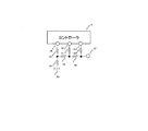
つぎに、図4におけるトーン発生回路11の具体例について図7を参照しながら説明する。図7において、符号13はコントローラを示し、符号60〜65はそれぞれ抵抗を示し、符号66はそれぞれグランドを示し、符号67は出力端子を示し、符号68〜70はそれぞれパルス信号を出力する端子を示す。
Next, a specific example of the
図7に示したトーン発生回路11は、一般的な3ビットのD/Aコンバータであり、図8に示すように端子68〜70から出力されるパルス信号を適切に制御して正弦波に近いトーン信号を出力端子67から出力させている。
しかしながら、図6に示した高域通過フィルタはかなりの部品数を必要とし、図7に示したトーン発生回路はコントローラの端子数が多くなるという課題があった。 However, the high-pass filter shown in FIG. 6 requires a considerable number of parts, and the tone generation circuit shown in FIG. 7 has a problem that the number of terminals of the controller is increased.
したがって、本発明は、部品数の削減とコントローラの端子数の低減を図ることを目的とする。 Accordingly, an object of the present invention is to reduce the number of components and the number of terminals of a controller.
上記課題を解決するために、本発明の無線通信回路は、高域通過フィルタを受信信号検波回路の後段に配置する第1の信号経路と、高域通過フィルタをマイクの後段に配置する第2の信号経路とを切り替える第1の切替手段を設け、第1の切替手段が第1の信号経路を選択したときに受信信号検波回路の出力信号を高域通過フィルタに通すことにより受信信号検波回路の出力信号に含まれるトーン信号を除去して音声信号を抽出し、第1の切替手段が第2の信号経路を選択したときにマイクから入力された音声信号を高域通過フィルタに通すことによりマイクから入力された音声信号に含まれるトーン信号周波数成分を除去するようにしている。 In order to solve the above-described problem, a wireless communication circuit of the present invention includes a first signal path in which a high-pass filter is disposed at the subsequent stage of the received signal detection circuit, and a second signal path in which the high-pass filter is disposed at the subsequent stage of the microphone. A first switching means for switching between the first signal path and the received signal detection circuit by passing the output signal of the received signal detection circuit through a high-pass filter when the first switching means selects the first signal path. The tone signal contained in the output signal is removed to extract the audio signal, and the audio signal input from the microphone when the first switching means selects the second signal path is passed through the high-pass filter. The tone signal frequency component contained in the audio signal input from the microphone is removed.
具体的には、受信信号検波回路およびマイク信号の増幅回路と高域通過フィルタの間と、高域通過フィルタとスピーカへの信号増幅回路および送信信号の振幅制限回路の間とに、それぞれスイッチを入れることで高域通過フィルタを送受信で共用させる。 Specifically, switches are respectively provided between the reception signal detection circuit and the microphone signal amplification circuit and the high-pass filter, and between the high-pass filter and the signal amplification circuit to the speaker and the amplitude limiting circuit of the transmission signal. By putting it in, the high-pass filter is shared for transmission and reception.
この構成によれば、受信信号検波回路の出力信号に含まれるトーン信号の除去と、マイクから入力された音声信号に含まれるトーン信号周波数成分の除去とに、一つの高域通過フィルタを共用することができ、高域通過フィルタを1つ削減できる。したがって、部品点数の削減を図ることができる。 According to this configuration, one high-pass filter is shared for the removal of the tone signal included in the output signal of the reception signal detection circuit and the removal of the tone signal frequency component included in the audio signal input from the microphone. And one high-pass filter can be reduced. Therefore, the number of parts can be reduced.
本発明の無線通信回路システムは、上記の無線通信回路と、この無線通信回路を制御する通信制御用のコントローラとを備えている。 A wireless communication circuit system of the present invention includes the above-described wireless communication circuit and a communication control controller that controls the wireless communication circuit.
本発明の無線通信機は、上記の無線通信回路システムを備えている。 The wireless communication device of the present invention includes the wireless communication circuit system described above.
上記の無線通信回路システムおよび無線通信機においては、それぞれ、低域通過フィルタを受信信号検波回路の出力信号中に含まれるトーン信号の周波数判別に使用する第1の信号経路と、低域通過フィルタを送信信号に含ませるトーン信号の生成に使用する第2の信号経路とを切り替える第2の切替手段を設け、第2の切替手段が第1の信号経路を選択したときに受信信号検波回路の出力信号を低域通過フィルタに通すことによってトーン信号の周波数を判別し、第2の切替手段が第2の信号経路を選択したときにコントローラから出力されるパルス信号を低域通過フィルタに通すことによりパルス信号から高調波を除去してトーン信号を生成することが好ましい。 In the wireless communication circuit system and the wireless communication device, the first signal path that uses the low-pass filter to determine the frequency of the tone signal included in the output signal of the received signal detection circuit, and the low-pass filter, respectively. Is provided with a second switching means for switching to a second signal path used to generate a tone signal to be included in the transmission signal, and when the second switching means selects the first signal path, the received signal detection circuit The frequency of the tone signal is determined by passing the output signal through the low-pass filter, and the pulse signal output from the controller when the second switching means selects the second signal path is passed through the low-pass filter. The tone signal is preferably generated by removing harmonics from the pulse signal.
具体的には、コントローラから出力したいトーン信号の周波数と同じパルス信号を出力させ、受信信号検波回路の後段の低域通過フィルタの前後にそれぞれスイッチを設け、送信時に上記パルス信号を低域通過フィルタに入力することで正弦波に近いトーン信号を発生させる。 Specifically, a pulse signal having the same frequency as the tone signal to be output from the controller is output, a switch is provided before and after the low-pass filter at the subsequent stage of the reception signal detection circuit, and the pulse signal is transmitted to the low-pass filter during transmission. To generate a tone signal close to a sine wave.
この構成によれば、受信信号検波回路の出力信号中に含まれるトーン信号の周波数判別に使用する低域通過フィルタを利用し、コントローラから出力されるパルス信号を低域通過フィルタに通すことによりパルス信号から高調波を除去してトーン信号を生成するので、トーン発生用に必要であったコントローラの端子数の削減と抵抗の削減ができる。 According to this configuration, the low-pass filter used for the frequency discrimination of the tone signal included in the output signal of the received signal detection circuit is used, and the pulse signal output from the controller is passed through the low-pass filter. Since the tone signal is generated by removing harmonics from the signal, the number of controller terminals and the resistance required for tone generation can be reduced.
本発明に係る無線通信機によると、高域通過フィルタを1つ削減でき、トーン発生用に必要であったコントローラの端子数の削減と抵抗の削減ができるので、無線通信機の低価格化や小型化が容易に実現できる。 According to the wireless communication device according to the present invention, one high-pass filter can be reduced, and the number of controller terminals and resistance required for tone generation can be reduced. Miniaturization can be easily realized.
以下、本発明の実施の形態を、図面を参照しながら説明する。 Hereinafter, embodiments of the present invention will be described with reference to the drawings.
(実施の形態1:請求項1に対応)
以下、本発明の実施の形態1に係る無線通信機について、図面を参照しながら説明する。
(Embodiment 1: corresponding to claim 1)
Hereinafter, a wireless communication apparatus according to Embodiment 1 of the present invention will be described with reference to the drawings.
なお、図4にて説明した部材に対応する部材には同一符号を付して詳しい説明は省略する。 In addition, the same code | symbol is attached | subjected to the member corresponding to the member demonstrated in FIG. 4, and detailed description is abbreviate | omitted.
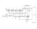
図1は本発明の実施の形態1を説明するための無線通信機の回路構成を示す。図1において、符号25はマイク9から入力された音声信号を高域通過フィルタ16に入力するか受信信号検波回路5の出力信号を高域通過フィルタ16に入力するかを選択するスイッチを示す。符号26は高域通過フィルタ16の出力信号をスピーカ8に伝達させるか送信信号の振幅制限回路20に伝達させるかを選択するスイッチを示す。
FIG. 1 shows a circuit configuration of a wireless communication device for explaining the first embodiment of the present invention. In FIG. 1,
この無線通信機においては、受信時にはスイッチ25、26をそれぞれa側に接続し、送信時にはb側に接続することで、図4に示した従来の無線通信機と同一の機能を実現することができる。
In this wireless communication device, the same functions as those of the conventional wireless communication device shown in FIG. 4 can be realized by connecting the
実施の形態1によると、高域通過フィルタを1つ削減することができるため、無線通信機の低価格化と小型化を容易に実現できる。 According to the first embodiment, since one high-pass filter can be reduced, it is possible to easily reduce the cost and size of the wireless communication device.
(実施の形態2:請求項4,5に対応)
以下、本発明の実施の形態2に係る無線通信機について、図面を参照しながら説明する。
(Embodiment 2: corresponding to
Hereinafter, a wireless communication apparatus according to
なお、図1、図4にて説明した部材に対応する部材には同一符号を付して詳しい説明は省略する。 Note that members corresponding to those described in FIGS. 1 and 4 are denoted by the same reference numerals, and detailed description thereof is omitted.
図2は本発明の実施の形態2を説明するための無線通信機の回路構成を示す。図2において、符号27はコントローラ13から出力されたパルス信号を低域通過フィルタ14に入力するか受信信号検波回路5の出力信号を低域通過フィルタ14に入力するかを選択するスイッチを示す。符号28は低域通過フィルタ14の出力信号をコンパレータ15に伝達させるか加算回路21に伝達させるかを選択するスイッチを示す。
FIG. 2 shows a circuit configuration of a wireless communication device for explaining the second embodiment of the present invention. In FIG. 2,
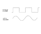
つぎに、図3を参照しながら、図2に示したトーン発生回路の構成について説明する。コントローラ13から実現させたいトーン信号と同一周波数のパルス信号を出力させ、スイッチ27をb側に接続し、低域通過フィルタ14に上記パルス信号を入力させる。そのようにすることで上記パルス信号の高調波成分が除去されるので、低域通過フィルタ14から出力される信号は、図8に示すような従来構成で実現されるトーン信号と同等に正弦波に近い信号となる。受信時にはスイッチ27、28をa側に接続することで、図4に示した従来の無線通信機と同一の機能を実現することができる。
Next, the configuration of the tone generation circuit shown in FIG. 2 will be described with reference to FIG. The
実施の形態2によると、従来3個以上必要であったコントローラ13のパルス出力端子を1個に削減できるとともに、抵抗も削減することができるので、無線通信機の低価格化と小型化を容易に実現できる。
According to the second embodiment, it is possible to reduce the number of pulse output terminals of the
以上説明したように、本発明は、無線通信機の低価格化と小型化を実施する際に有用である。 As described above, the present invention is useful when reducing the price and size of a wireless communication device.
1 アンテナ
2 アンテナ切替回路
3 受信選局回路
4 増幅回路
5 受信信号検波回路
6 トーン周波数判別回路
7 増幅回路
8 スピーカ
9 マイク
10 送信変調回路
11 トーン発生回路
12 送信電力増幅回路
13 コントローラ
14、22 低域通過フィルタ
15 コンパレータ
16、19 高域通過フィルタ
17、18 増幅回路
20 振幅制限回路
21 加算回路
23 電圧制御発振器
25〜28 スイッチ
30 高域通過フィルタの周波数特性
31 低域通過フィルタの周波数特性
35〜39、60〜65 抵抗
40〜46 コンデンサ
47、48 演算増幅器
49〜51、66 グランド
52、53 基準電圧
54 入力端子
55、67〜70 出力端子
DESCRIPTION OF SYMBOLS 1
Claims (5)
前記第2の切替手段が第1の信号経路を選択したときに前記受信信号検波回路の出力信号を前記低域通過フィルタに通すことによってトーン信号の周波数を判別し、前記第2の切替手段が第2の信号経路を選択したときに前記コントローラから出力されるパルス信号を前記低域通過フィルタに通すことにより前記パルス信号から高調波を除去してトーン信号を生成する請求項2記載の無線通信回路システム。 A first signal path that uses a low-pass filter for frequency discrimination of a tone signal included in the output signal of the reception signal detection circuit, and a tone signal that includes the low-pass filter in a transmission signal Providing a second switching means for switching between the second signal path,
When the second switching means selects the first signal path, the output signal of the received signal detection circuit is passed through the low-pass filter to determine the frequency of the tone signal, and the second switching means 3. The wireless communication according to claim 2, wherein when a second signal path is selected, a pulse signal output from the controller is passed through the low-pass filter to remove harmonics from the pulse signal and generate a tone signal. Circuit system.
前記第2の切替手段が第1の信号経路を選択したときに前記受信信号検波回路の出力信号を前記低域通過フィルタに通すことによってトーン信号の周波数を判別し、前記第2の切替手段が第2の信号経路を選択したときに前記コントローラから出力されるパルス信号を前記低域通過フィルタに通すことにより前記パルス信号から高調波を除去してトーン信号を生成する請求項3記載の無線通信機。
A first signal path that uses a low-pass filter for frequency discrimination of a tone signal included in the output signal of the reception signal detection circuit, and a tone signal that includes the low-pass filter in a transmission signal Providing a second switching means for switching between the second signal path,
When the second switching means selects the first signal path, the output signal of the received signal detection circuit is passed through the low-pass filter to determine the frequency of the tone signal, and the second switching means 4. The wireless communication according to claim 3, wherein when a second signal path is selected, a pulse signal output from the controller is passed through the low-pass filter to remove harmonics from the pulse signal and generate a tone signal. Machine.
Priority Applications (2)
| Application Number | Priority Date | Filing Date | Title |
|---|---|---|---|
| JP2004249108A JP2006067378A (en) | 2004-08-27 | 2004-08-27 | Radio transmission circuit, system thereof and radio transmission device |
| US11/210,664 US20060111138A1 (en) | 2004-08-27 | 2005-08-25 | Wireless communication circuit, wireless communication circuit system, and wireless communication apparatus |
Applications Claiming Priority (1)
| Application Number | Priority Date | Filing Date | Title |
|---|---|---|---|
| JP2004249108A JP2006067378A (en) | 2004-08-27 | 2004-08-27 | Radio transmission circuit, system thereof and radio transmission device |
Publications (1)
| Publication Number | Publication Date |
|---|---|
| JP2006067378A true JP2006067378A (en) | 2006-03-09 |
Family
ID=36113430
Family Applications (1)
| Application Number | Title | Priority Date | Filing Date |
|---|---|---|---|
| JP2004249108A Pending JP2006067378A (en) | 2004-08-27 | 2004-08-27 | Radio transmission circuit, system thereof and radio transmission device |
Country Status (2)
| Country | Link |
|---|---|
| US (1) | US20060111138A1 (en) |
| JP (1) | JP2006067378A (en) |
Families Citing this family (2)
| Publication number | Priority date | Publication date | Assignee | Title |
|---|---|---|---|---|
| US20080233892A1 (en) * | 2007-03-19 | 2008-09-25 | Bojko Marholev | Method and system for an integrated vco and local oscillator architecture for an integrated fm transmitter and fm receiver |
| US7728676B2 (en) * | 2007-09-17 | 2010-06-01 | Atheros Communications, Inc. | Voltage-controlled oscillator with control range limiter |
Family Cites Families (4)
| Publication number | Priority date | Publication date | Assignee | Title |
|---|---|---|---|---|
| US3717816A (en) * | 1971-03-19 | 1973-02-20 | Siemens Ag | Impulse-scanned n-path filter for several frequency ranges |
| US6510309B1 (en) * | 1996-11-20 | 2003-01-21 | Conexant Systems, Inc. | Intermediate frequency amplifier circuit for use in receive and transmit modes |
| US5966646A (en) * | 1997-05-13 | 1999-10-12 | Ericsson, Inc. | Dual-band radio receiver |
| US6400821B1 (en) * | 1998-05-29 | 2002-06-04 | Motorola, Inc. | Digital tone generator |
-
2004
- 2004-08-27 JP JP2004249108A patent/JP2006067378A/en active Pending
-
2005
- 2005-08-25 US US11/210,664 patent/US20060111138A1/en not_active Abandoned
Also Published As
| Publication number | Publication date |
|---|---|
| US20060111138A1 (en) | 2006-05-25 |
Similar Documents
| Publication | Publication Date | Title |
|---|---|---|
| EP1847101B1 (en) | Audio device for improved sound reproduction | |
| US7574009B2 (en) | Method and apparatus for controlling the reproduction in audio signals in electroacoustic converters | |
| WO2016040450A1 (en) | A passive headset with dynamically controlled leds | |
| CN101512896B (en) | Digital amplifier | |
| US7382887B2 (en) | Method and device for reducing high frequency error components of a multi-channel modulator | |
| JP2006067378A (en) | Radio transmission circuit, system thereof and radio transmission device | |
| US7508263B2 (en) | Digital amplifying apparatus with noise reduction | |
| JP2006191430A (en) | Radio receiver | |
| JP2004254184A (en) | Device for removing noise | |
| KR20060041033A (en) | Digital audio amplifier, audio system including the same, and method of amplifying an audio signal | |
| JP2007028290A (en) | Am radio receiving circuit | |
| JP2008154135A (en) | Class-d amplifier | |
| JP2000023282A (en) | Acoustic reproducer | |
| JP6670117B2 (en) | Reception support device and reception support method | |
| JP3786593B2 (en) | Receiver | |
| JP2006222819A (en) | Adjacent band monitor device in radio receiver | |
| JP5553011B2 (en) | CTCSS transmitter | |
| JP6434822B2 (en) | COMMUNICATION DEVICE AND COMMUNICATION DEVICE CONTROL METHOD | |
| JP5634830B2 (en) | Frequency converter | |
| JP4860400B2 (en) | Receiver | |
| JP2004072576A (en) | Frequency modulation tuner | |
| JP2011146946A (en) | Communication apparatus | |
| JP2002016510A (en) | Wireless receiver | |
| JP2005341046A (en) | Noise reduction circuit, digital wireless communication apparatus, and noise reduction method | |
| KR19990035192A (en) | Noise Reduction Device for Radio Reception System |
Legal Events
| Date | Code | Title | Description |
|---|---|---|---|
| RD04 | Notification of resignation of power of attorney |
Free format text: JAPANESE INTERMEDIATE CODE: A7424 Effective date: 20060727 |