JP2006052084A - Garbage truck with measuring device - Google Patents
Garbage truck with measuring device Download PDFInfo
- Publication number
- JP2006052084A JP2006052084A JP2004253826A JP2004253826A JP2006052084A JP 2006052084 A JP2006052084 A JP 2006052084A JP 2004253826 A JP2004253826 A JP 2004253826A JP 2004253826 A JP2004253826 A JP 2004253826A JP 2006052084 A JP2006052084 A JP 2006052084A
- Authority
- JP
- Japan
- Prior art keywords
- cylinder
- garbage
- storage chamber
- load
- measuring
- Prior art date
- Legal status (The legal status is an assumption and is not a legal conclusion. Google has not performed a legal analysis and makes no representation as to the accuracy of the status listed.)
- Pending
Links
Images


Landscapes
- Refuse-Collection Vehicles (AREA)
Abstract
Description
本発明は、計量器を備えたゴミ収集車に関する。 The present invention relates to a garbage truck equipped with a measuring instrument.
従来、ゴミ収集車のゴミの計量方法は色々有るが、今現在主流と成っているのがゴミをゴミ収集車に積み込んだ後ゴミの重量を計量する方法である。この計量方法はゴミ収容室と車体のシャシーフレームの上面間に4個のロードセルを取り付けて計量するものである(例えば特許文献1参照)。 Conventionally, there are various methods for measuring garbage in garbage trucks. Currently, the mainstream method is to measure the weight of garbage after loading garbage into the garbage truck. In this measuring method, four load cells are attached between the dust storage chamber and the upper surface of the chassis frame of the vehicle body (for example, see Patent Document 1).
ところで、この方法はロードセルに加わる荷重が走行時でも常に加重されており、しかも4点のみの加重であるため、ロードセル・シャシーフレーム・ゴミ収容室等の強度不足、路面の凹凸による計量誤差の問題が指摘されている。又4点ロードセル方式ではゴミ収容室とシャシーフレームがロードセルに固定されている為、ダンプ排出方式のゴミ収集車には取り付けが困難であった。
本発明が解決しようとする課題は、従来のこれらの問題点を解消し、一般に多く使用されているダンプ排出方式のゴミ収集車にロードセルを取り付け可能にし、しかも強度を保持して安全で正確な計量を行えるようにした計量器付きゴミ収集車を提供することにある。 The problem to be solved by the present invention is to solve these conventional problems, make it possible to attach a load cell to a garbage collection vehicle of a dump discharge method that is generally used, and to maintain the strength and to be safe and accurate. The object is to provide a garbage truck with a measuring instrument which can measure.
かかる課題を解決した本発明の構成は、
1) ゴミを収容するゴミ収容室を車体のシャシーフレームに載置し、同ゴミ収容室の後端左右下部をシャシーフレームにピンで回動自在に軸支し、ゴミ収容室とシャシーフレームとの間に排出用主シリンダを介装し、同排出用主シリンダを作動させてゴミ収容室を後側へ傾倒させてゴミ収容室内のゴミを排出できるようにしたダンプ式のゴミ収集車において、前記シャシーフレームの前部に計量用シリンダを立設し、同計量用シリンダのケース又はロッドの端部をその伸長時に受ける受部材をゴミ収容室の前面に突設し、計量用シリンダとシャシーフレームとの間及び各ピンとシャシーフレームとの間にロードセルをそれぞれ介装し、各ロードセルの値からゴミ収容室内のゴミの重量を算出する演算手段を設け、計量用シリンダの伸長によるゴミ収容室の上昇時に排出用主シリンダを解放させることでゴミ収容室の自重及びゴミ収容室内のゴミの重量が各ロードセルに荷重されて計量できるようにしたことを特徴とする計量器付きゴミ収集車
2) 計量時に排出用主シリンダへのゴミ収容室の荷重を非伝達状態にし、非計量時に荷重を伝達状態にする荷重伝達切換手段を設けた前記1)記載の計量器付きゴミ収集車
3) 荷重伝達切換手段が、排出用主シリンダのシリンダロッド又はシリンダケースにピン受筒を設け、ゴミ収容室の腹部にピン受部を設け、同ピン受部と前記ピン受筒に小径部と大径部を備えた連結ピンを連通し、同連結ピンを左右に進退させるピン動作用シリンダを設けた構造で、非計量時は連結ピンの大径部とピン受筒を嵌合して密着することで荷重を伝達し、計量時は連結ピンの小径部とピン受筒を嵌合して生じた隙間で荷重を非伝達状態にすることで正確に計量できるようにした前記2)記載の計量器付きゴミ収集車
4) 計量用シリンダに伸縮量の上下限を規制するスイッチを設けた前記1)〜3)いずれか記載の計量器付きゴミ収集車
5) 演算手段に投入したゴミの重量値及びその回収に必要な費用を表示する表示器を設けた前記1)〜4)いずれか記載の計量器付きゴミ収集車
にある。
The configuration of the present invention that solves this problem is as follows.
1) Place the trash storage chamber for storing trash on the chassis frame of the vehicle body, and pivotally support the rear left and right lower ends of the trash storage chamber with pins on the chassis frame. In the dump-type garbage collection vehicle, in which the main cylinder for discharge is interposed between the two and the main cylinder for discharge is operated to tilt the garbage storage chamber to the rear side so that the garbage in the garbage storage chamber can be discharged. A measuring cylinder is erected at the front of the chassis frame, and a receiving member that receives the end of the case or rod of the measuring cylinder when it is extended projects from the front of the dust storage chamber. Load cells between the pins and the chassis frame, and calculation means for calculating the weight of the waste in the waste storage chamber from the value of each load cell is provided. Garbage collection with a measuring instrument, characterized by releasing the main cylinder for discharging when the garbage storage chamber is raised, so that the weight of the garbage storage chamber and the weight of the garbage in the garbage storage chamber can be loaded and measured on each load cell. Vehicle 2) The
本発明によれば、走行時はゴミ収容室はシャシーフレーム上にあって強度は十分に保持されて安全であり、ロードセル・シャシーフレーム・ゴミ収容室等は今まで使用されているゴミ収集車と変わりなく、計量時はロードセル3点で計量する為、少々の凹凸路面で計量しても3点のどのロードセルにも荷重が加わり正確な計量が出来るようになる。 According to the present invention, when traveling, the garbage storage chamber is on the chassis frame, and the strength is sufficiently maintained and safe, and the load cell, chassis frame, garbage storage chamber, etc. Since the measurement is performed at three load cells at the time of measurement, a load is applied to any of the three load cells even when measuring on a slightly uneven road surface so that accurate measurement can be performed.
本発明のゴミ収容室は車体を構成するシャシーフレームあるいはサイドメンバに載置されるのが一般的であるが、荷台を介在して荷台上に離間自在に載置することもできる。ゴミ収容室の両側下部には車体上に所定高さに支持する支持脚を設けることもあるが、長手方向に沿って細長いフレームを取り付けて、車体上に載置したときに荷重が均一に作用できるようにするのが望ましい。 The dust storage chamber of the present invention is generally placed on a chassis frame or a side member that constitutes the vehicle body, but can be placed on the cargo bed in a separable manner via a cargo bed. Support legs that support the vehicle body at a predetermined height may be provided at the lower part on both sides of the garbage storage chamber, but a load is applied evenly when an elongated frame is attached along the longitudinal direction and placed on the vehicle body. It is desirable to be able to do it.
計量用シリンダは油圧モータポンプや電磁油圧切替バルブ等で作動させる油圧リフトシリンダが一般的に用いられるが、その他ゴミ収容室を昇降できる手段であれば全て採用できる。以下、本発明の実施例を図面に基づいて具体的に説明する。 As the measuring cylinder, a hydraulic lift cylinder that is operated by a hydraulic motor pump, an electromagnetic hydraulic pressure switching valve, or the like is generally used. However, any other means that can raise and lower the dust storage chamber can be adopted. Embodiments of the present invention will be specifically described below with reference to the drawings.
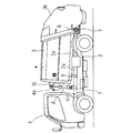
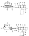
図1は実施例の計量器付きゴミ収集車の説明図、図2は実施例の後部のロードセルの説明図、図3は実施例の計量用シリンダの説明図、図4は実施例のロードセルの位置を示す平面図、図5は実施例のピン動作用シリンダの説明図、図6は実施例の係止片の説明図、図7は実施例のゴミ排出時を示す説明図、図8は実施例の計量状態を示す説明図、図9は実施例のピン動作用シリンダの動作を示す説明図である。 FIG. 1 is an explanatory view of a garbage truck with a measuring instrument according to an embodiment, FIG. 2 is an explanatory view of a load cell at the rear of the embodiment, FIG. 3 is an explanatory view of a measuring cylinder of the embodiment, and FIG. FIG. 5 is an explanatory view of the cylinder for pin operation of the embodiment, FIG. 6 is an explanatory view of the locking piece of the embodiment, FIG. 7 is an explanatory view showing dust discharge of the embodiment, and FIG. FIG. 9 is an explanatory view showing the operation of the pin operation cylinder of the embodiment.
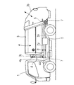
図中、1は車体、2はシャシーフレーム、2aはサブフレームである。3はゴミ収容室であって、下部両端には長手方向に沿ってフレーム3aをそれぞれ取り付け、排出用主シリンダ3dで傾倒させてサブフレーム2aと離間自在に載置している。3bはテールゲート、3eは排出用主シリンダ油圧回路である。
In the figure, 1 is a vehicle body, 2 is a chassis frame, and 2a is a sub-frame.
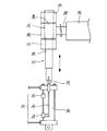
排出用主シリンダ3dはそのシリンダロッド3gの先端部にピン受筒3hを取り付け、ゴミ収容室3の腹部に一対のピン受部3iを設け、外径を左右異径にした連結ピン3jでゴミ収容室3の腹部と枢支している。3kは小径部、3mは大径部、3nはピン穴である。3pはピン動作用シリンダであって、ゴミ収容室3の腹面に取り付けられ、そのシリンダロッド3qに前記連結ピン3jを連結して左右へスライドできるようにしている。連結ピン3jの小径部3kと大径部3mの段差はテーパーを形成してスライドが円滑に行なえるようにしている。3rはピン動作用シリンダ油圧回路である。
The
3sは近接スイッチであって、ピン動作用シリンダ3pのシリンダロッド3qの進退量の上下限を規制するもので、上限スイッチ3tと下限スイッチ3uをそれぞれピン動作用シリンダ3pのケースに取り付け、各スイッチ3t,3uの信号を受けるセンサープレート3vをシリンダロッド3qに取り付け、シリンダロッド3qを左右に進退させて各スイッチ3t,3uがセンサープレート3vと接すると、ピン動作用シリンダ3pを停止させて小径部3k又は大径部3mで枢支を保持できるようにしている。
3s is a proximity switch which regulates the upper and lower limits of the cylinder rod 3q of the
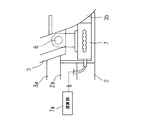
4は計量用シリンダであって、ゴミ収容室3の前面にフック3cを取り付け、同フック3cに掛止するシリンダロッド4aを上部に備えたシリンダケース4bをサブフレーム2aに回動自在に軸支している。計量用シリンダ4は図示しない油圧モータポンプと電磁油圧切替バルブによりシリンダロッド4aを伸長させてその上端部をフック3cに掛止するようにしている。4cは計量用シリンダ油圧回路、4dは排出用主シリンダ油圧回路3eと計量用シリンダ油圧回路4cとピン動作用シリンダ油圧回路3rの切換を行なう油圧制御部、4eは油圧制御部4dを操作する計量操作盤である。
5は規制スイッチであって、計量用シリンダ4のシリンダロッド4aの昇降量の上下限を規制するもので、近接スイッチを用いた上限スイッチ5aと下限スイッチ5bをそれぞれシリンダケース4b側に取り付けるとともに各スイッチ5a,5bの信号を受けるセンサープレート5cをシリンダロッド4a側に取り付け、シリンダロッド4aを上下に昇降させて各スイッチ5a,5bがセンサープレート5cと接すると、上下限位置の信号が上下限表示装置5dに伝達されて計量用シリンダ4を停止するとともにランプやブザーにより作業者に知らせるようにしている。
6はピンであって、ゴミ収容室3後部の左右両側下部にそれぞれ設けてシャシーフレーム2に対して回動自在に軸支している。7はロードセルであって、シリンダケース4bの下部及びピン6とシャシーフレーム2との間に取り付けている。各ロードセル7は演算部7a及び運転席等に設置された表示器7bと接続し、計量用シリンダ4のシリンダロッド4aとフック3cとの掛止時に収容されたゴミを含むゴミ収容室3の荷重が作用して信号が送信され、重量を計量してその重量値及びその回収に必要な費用を表示できるようにしている。
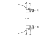
8は係止片であって、サブフレーム2aの前部の左右側面にそれぞれ取り付けてゴミ収容室3のフレーム3aを左右から支持し、ゴミ収容室3をサブフレーム2aに載置しているときに車体1の走行等の振動による位置ずれを防止できるようにしている。
本実施例では、図1に示すように走行時など非計量時ではゴミ収容室3をサブフレーム2a上に載置しており、ゴミ収容室3による荷重の大部分はサブフレーム2aに作用している。ゴミ収容室3のフレーム3aはサブフレーム2aに当接して支持されており、荷重は均一に作用してサブフレーム2aとゴミ収容室3の支持強度は十分保持できるものである。しかも走行時の揺れ等に対してもサブフレーム2aの左右両側の係止片8で支持しているから、ゴミ収容室3の載置位置が左右にずれることもない。
In this embodiment, as shown in FIG. 1, the
ゴミ排出時の作業は、図7に示すようにテールゲート3bに備えた図示しないテールゲート上昇シリンダによりテールゲート3bを上昇させてゴミ収容室3の後部を開口させた後、排出用主シリンダ3dで大きく傾倒させ、ゴミの重力によりゴミを排出させる。このときの荷重は後部左右の各ロードセル7と排出用主シリンダ3dのみに作用している。また、図9(a)に示すように排出時及び走行時等の非計量時はピン動作用シリンダ油圧回路3rによりピン動作用シリンダ3pのシリンダロッド3qを後退させて連結ピン3jの大径部3mでシリンダロッド3gのピン受筒3hと密接して枢支し、荷重が伝達されるようにしている。
As shown in FIG. 7, the dust discharge operation is performed by raising the
計量時はゴミ収容室3のテールゲート3bの開口部からゴミを投入し、計量操作盤4eを操作して図8に示すように計量用シリンダ4のシリンダロッド4aを上昇させるとその上端部がゴミ収容室3のフック3cと掛止してゴミ収容室3のフレーム3aがサブフレーム2aより10〜15cm離間し、計量用シリンダ4及び左右の各ピン6の3点で支持されてゴミ収容室3及びゴミ収容室3内のゴミの荷重が各ロードセル7にのみ作用している状態となる。
At the time of measurement, dust is introduced from the opening of the
このときゴミ排出時に作動する排出用主シリンダ3dの排出用主シリンダ油圧回路3eは油圧制御部4dにより開放となっている。また、図9(b)に示すようにピン動作用シリンダ3pのシリンダロッド3qをピン動作用シリンダ油圧回路3rにより前進させて連結ピン3jの小径部3kでシリンダロッド3gのピン受筒3hと枢支させる。このときに連結ピン3jの小径部3kとピン受筒3hのピン穴3nとの間に隙間が生じて小径部3kとピン穴3nとの接触面積が減少し、荷重が非伝達状態となることで正確に計量される。各ロードセル7の値は演算部7aに送信されて重量が算出され、表示器7bに重量値及び費用が表示される。
At this time, the discharge main cylinder
本実施例はこのように構成したから、走行時はゴミ収容室はシャシーフレーム上にあって強度は十分に保持されて安全であり、ロードセル・シャシーフレーム・ゴミ収容室等は今まで使用されているゴミ収集車と変わりなく、計量時はロードセル3点で計量する為、少々の凹凸路面で計量しても3点のどのロードセルにも荷重が加わり正確な計量が出来るようになった。 Since the present embodiment is configured as described above, the garbage storage chamber is located on the chassis frame during driving and the strength is sufficiently maintained to be safe, and the load cell, chassis frame, garbage storage chamber, etc. have been used so far. As is the case with the garbage truck, the load cell is measured at 3 points, so even if it is measured on a slightly uneven road surface, a load is applied to any of the 3 load cells so that accurate measurement can be performed.
本発明の計量器付きゴミ収集車は、主として家庭から出る一般ゴミの収集用に用いられるが、その他、産業廃棄物の運搬車輌等にも応用できる。 The garbage truck with a measuring instrument of the present invention is mainly used for collecting general garbage from a home, but can also be applied to a vehicle for transporting industrial waste.
1 車体
2 シャシーフレーム
2a サブフレーム
3 ゴミ収容室
3a フレーム
3b テールゲート
3c フック
3d 排出用主シリンダ
3e 排出用主シリンダ油圧回路
3g シリンダロッド
3h ピン受筒
3i ピン受部
3j 連結ピン
3k 小径部
3m 大径部
3n ピン穴
3p ピン動作用シリンダ
3q シリンダロッド
3r ピン動作用シリンダ油圧回路
3s 近接スイッチ
3t 上限スイッチ
3u 下限スイッチ
3v センサープレート
4 計量用シリンダ
4a シリンダロッド
4b シリンダケース
4c 計量用シリンダ油圧回路
4d 油圧制御部
4e 計量操作盤
5 規制スイッチ
5a 上限スイッチ
5b 下限スイッチ
5c センサープレート
5d 上下限表示装置
6 ピン
7 ロードセル
7a 演算部
7b 表示器
8 係止片
DESCRIPTION OF
Claims (5)
Priority Applications (1)
| Application Number | Priority Date | Filing Date | Title |
|---|---|---|---|
| JP2004253826A JP2006052084A (en) | 2004-07-14 | 2004-09-01 | Garbage truck with measuring device |
Applications Claiming Priority (2)
| Application Number | Priority Date | Filing Date | Title |
|---|---|---|---|
| JP2004206790 | 2004-07-14 | ||
| JP2004253826A JP2006052084A (en) | 2004-07-14 | 2004-09-01 | Garbage truck with measuring device |
Publications (1)
| Publication Number | Publication Date |
|---|---|
| JP2006052084A true JP2006052084A (en) | 2006-02-23 |
Family
ID=36029802
Family Applications (1)
| Application Number | Title | Priority Date | Filing Date |
|---|---|---|---|
| JP2004253826A Pending JP2006052084A (en) | 2004-07-14 | 2004-09-01 | Garbage truck with measuring device |
Country Status (1)
| Country | Link |
|---|---|
| JP (1) | JP2006052084A (en) |
Cited By (11)
| Publication number | Priority date | Publication date | Assignee | Title |
|---|---|---|---|---|
| GB2449548A (en) * | 2007-05-22 | 2008-11-26 | Multilift Oy | Method and apparatus for weighing a load body of a vehicle |
| JP2009184375A (en) * | 2008-02-01 | 2009-08-20 | Kyokuto Kaihatsu Kogyo Co Ltd | Cargo handling vehicle |
| JP2010064574A (en) * | 2008-09-10 | 2010-03-25 | Kyokuto Kaihatsu Kogyo Co Ltd | Cargo handling vehicle |
| JP2010064573A (en) * | 2008-09-10 | 2010-03-25 | Kyokuto Kaihatsu Kogyo Co Ltd | Cargo handling vehicle |
| JP2011225095A (en) * | 2010-04-20 | 2011-11-10 | Kyokuto Kaihatsu Kogyo Co Ltd | Working vehicle |
| CH704466A1 (en) * | 2011-02-11 | 2012-08-15 | Digi Sens Ag | Method and apparatus for measuring the weight of a to a loading area to hievenden load. |
| EP2594534A1 (en) | 2011-11-16 | 2013-05-22 | JFE Advantech Co. Ltd. | Weighing apparatus |
| CN108313592A (en) * | 2018-03-08 | 2018-07-24 | 南安市如兴智能家居开发有限公司 | A kind of laborsaving garbage truck of environmental sanitation |
| JP2019156350A (en) * | 2018-03-16 | 2019-09-19 | 極東開発工業株式会社 | Specially-equipped vehicle with weighing function |
| CN113942767A (en) * | 2021-10-28 | 2022-01-18 | 武汉中绘炫图信息科技有限公司 | Garbage classification transfer system based on Internet of things |
| CN115489907A (en) * | 2022-09-28 | 2022-12-20 | 郑州森鹏电子技术股份有限公司 | Low-power-consumption wireless weighing system and garbage truck |
-
2004
- 2004-09-01 JP JP2004253826A patent/JP2006052084A/en active Pending
Cited By (17)
| Publication number | Priority date | Publication date | Assignee | Title |
|---|---|---|---|---|
| GB2449548B (en) * | 2007-05-22 | 2010-08-18 | Multilift Oy | Method and apparatus for weighing a load body of a vehicle |
| GB2449548A (en) * | 2007-05-22 | 2008-11-26 | Multilift Oy | Method and apparatus for weighing a load body of a vehicle |
| JP2009184375A (en) * | 2008-02-01 | 2009-08-20 | Kyokuto Kaihatsu Kogyo Co Ltd | Cargo handling vehicle |
| JP2010064574A (en) * | 2008-09-10 | 2010-03-25 | Kyokuto Kaihatsu Kogyo Co Ltd | Cargo handling vehicle |
| JP2010064573A (en) * | 2008-09-10 | 2010-03-25 | Kyokuto Kaihatsu Kogyo Co Ltd | Cargo handling vehicle |
| JP2011225095A (en) * | 2010-04-20 | 2011-11-10 | Kyokuto Kaihatsu Kogyo Co Ltd | Working vehicle |
| US9534948B2 (en) | 2011-02-11 | 2017-01-03 | Digi Sens Ag | Method and device for measuring the weight of a load to be hoisted onto a loading area |
| CH704466A1 (en) * | 2011-02-11 | 2012-08-15 | Digi Sens Ag | Method and apparatus for measuring the weight of a to a loading area to hievenden load. |
| WO2012106826A1 (en) * | 2011-02-11 | 2012-08-16 | Digi Sens Ag | Method and device for measuring the weight of a load to be hoisted onto a loading area |
| EP2594534A1 (en) | 2011-11-16 | 2013-05-22 | JFE Advantech Co. Ltd. | Weighing apparatus |
| CN108313592A (en) * | 2018-03-08 | 2018-07-24 | 南安市如兴智能家居开发有限公司 | A kind of laborsaving garbage truck of environmental sanitation |
| JP2019156350A (en) * | 2018-03-16 | 2019-09-19 | 極東開発工業株式会社 | Specially-equipped vehicle with weighing function |
| JP7244210B2 (en) | 2018-03-16 | 2023-03-22 | 極東開発工業株式会社 | Specially equipped vehicle with weighing function |
| CN113942767A (en) * | 2021-10-28 | 2022-01-18 | 武汉中绘炫图信息科技有限公司 | Garbage classification transfer system based on Internet of things |
| CN113942767B (en) * | 2021-10-28 | 2022-11-04 | 中国地质大学(武汉) | Garbage classification transfer system based on Internet of things |
| CN115489907A (en) * | 2022-09-28 | 2022-12-20 | 郑州森鹏电子技术股份有限公司 | Low-power-consumption wireless weighing system and garbage truck |
| CN115489907B (en) * | 2022-09-28 | 2024-05-03 | 郑州森鹏电子技术股份有限公司 | Low-power consumption wireless weighing system and garbage truck |
Similar Documents
| Publication | Publication Date | Title |
|---|---|---|
| JP2006052084A (en) | Garbage truck with measuring device | |
| CN206012406U (en) | Dumper | |
| JP5465085B2 (en) | Weight weighing device | |
| EP2304396A1 (en) | Load monitoring system | |
| GB2554836A (en) | Weighing system for a front-end-loading waste-hauling vehicle | |
| ES2660034T3 (en) | Weighing system and procedure for weighing a load of an articulated dump truck | |
| JP2007155410A (en) | Calibrating method for vehicle-use load weight detecting device | |
| CN205706328U (en) | Empty body determines system, dumper, self-discharging vehicle and hydraulic pressure cylinder assembly | |
| JP4878931B2 (en) | Load weight measuring device for cargo handling vehicles | |
| JPH0893045A (en) | Tank vehicle | |
| JP5222577B2 (en) | Cargo handling vehicle | |
| JP3474541B2 (en) | In-vehicle scale | |
| JP4972463B2 (en) | Cargo handling vehicle | |
| JP4537220B2 (en) | Garbage truck | |
| JP3684177B2 (en) | Tank tank with measuring instrument | |
| JP4294419B2 (en) | Device for measuring the weight of a load in a container handling vehicle | |
| CN211924171U (en) | Shield constructs uses dregs car | |
| US3017938A (en) | Method and apparatus for weighing | |
| JP3118209B2 (en) | In-vehicle weighing device | |
| JP2005001853A (en) | Refuse collecting vehicle | |
| JPH07209063A (en) | Waste collecting working vehicle | |
| JPH0290023A (en) | Weighing apparatus for load on dump truck | |
| JPS61191927A (en) | Load weight measuring apparatus for dump truck | |
| JP2006137543A (en) | Vehicle operation control system interlocked with metering apparatus | |
| JP3824557B2 (en) | In-vehicle weighing device |
Legal Events
| Date | Code | Title | Description |
|---|---|---|---|
| A621 | Written request for application examination |
Free format text: JAPANESE INTERMEDIATE CODE: A621 Effective date: 20061124 |
|
| A131 | Notification of reasons for refusal |
Free format text: JAPANESE INTERMEDIATE CODE: A131 Effective date: 20090622 |
|
| A02 | Decision of refusal |
Free format text: JAPANESE INTERMEDIATE CODE: A02 Effective date: 20091102 |