JP2006035786A - Ink-jet recorder - Google Patents
Ink-jet recorder Download PDFInfo
- Publication number
- JP2006035786A JP2006035786A JP2004222753A JP2004222753A JP2006035786A JP 2006035786 A JP2006035786 A JP 2006035786A JP 2004222753 A JP2004222753 A JP 2004222753A JP 2004222753 A JP2004222753 A JP 2004222753A JP 2006035786 A JP2006035786 A JP 2006035786A
- Authority
- JP
- Japan
- Prior art keywords
- ink
- discharge port
- dye
- pigment
- recording
- Prior art date
- Legal status (The legal status is an assumption and is not a legal conclusion. Google has not performed a legal analysis and makes no representation as to the accuracy of the status listed.)
- Withdrawn
Links
Images


Classifications
-
- B—PERFORMING OPERATIONS; TRANSPORTING
- B41—PRINTING; LINING MACHINES; TYPEWRITERS; STAMPS
- B41J—TYPEWRITERS; SELECTIVE PRINTING MECHANISMS, i.e. MECHANISMS PRINTING OTHERWISE THAN FROM A FORME; CORRECTION OF TYPOGRAPHICAL ERRORS
- B41J2/00—Typewriters or selective printing mechanisms characterised by the printing or marking process for which they are designed
- B41J2/005—Typewriters or selective printing mechanisms characterised by the printing or marking process for which they are designed characterised by bringing liquid or particles selectively into contact with a printing material
- B41J2/01—Ink jet
- B41J2/135—Nozzles
- B41J2/14—Structure thereof only for on-demand ink jet heads
- B41J2/14016—Structure of bubble jet print heads
- B41J2/14145—Structure of the manifold
Landscapes
- Ink Jet (AREA)
Abstract
Description
本発明は顔料インクと染料インクを用いて記録を行うインクジェット記録装置に関する。 The present invention relates to an ink jet recording apparatus that performs recording using pigment ink and dye ink.
プリンタ、複写機、ファクシミリ等の機能を有する記録装置、あるいはコンピュータやワードプロセッサ等を含む複合電子機器やワークステーションなどの出力機器として用いられる記録装置は、画像情報に基づいて紙やプラスチックシートなどの記録媒体に画像を形成していくように構成されている。前記記録装置のうち、記録ヘッドから記録媒体へインクを吐出して記録を行うインクジェット記録装置は、記録ヘッドのコンパクト化が容易であり、高精細な画像を高速で記録することができ、普通紙に特別な処理をせずに記録することができ、ノンインパクト方式であるため騒音が少なく、しかも多種類のインクを使用してカラー画像を形成するのが容易であるなどの利点を有している。 Recording devices having functions such as printers, copiers, facsimiles, etc., or recording devices used as output devices such as composite electronic devices and workstations including computers and word processors, record paper and plastic sheets based on image information. An image is formed on a medium. Among the recording apparatuses, an inkjet recording apparatus that performs recording by discharging ink from a recording head to a recording medium is easy to make the recording head compact and can record high-definition images at high speed. In addition, the non-impact method enables recording without any special processing, and has the advantages of low noise and easy formation of color images using various types of ink. Yes.
上記インクジェット記録装置においては、記録ヘッドとして一般に微細な吐出口を配列したものが用いられるので、吐出口内への気泡や塵埃の混入が生じたり、あるいはインク溶剤の蒸発に伴ってインクが増粘するなどしてインク滴の吐出不良が発生することがある。このような吐出不良が発生した場合には、記録ヘッド内のインクをリフレッシュすることによりそれら吐出不良要因を除去するための吐出回復処理が行われる。 In the above-described ink jet recording apparatus, a recording head in which fine discharge ports are generally arranged is used, so that bubbles and dust are mixed into the discharge ports, or the ink thickens as the ink solvent evaporates. For example, ink droplet ejection defects may occur. When such a discharge failure occurs, a discharge recovery process is performed to remove these discharge failure factors by refreshing the ink in the recording head.
前記吐出回復処理を行う手段として、吐出口内のインクを加圧することによりインクを強制的に吐出させる加圧回復手段や、吐出口内のインクに負圧を作用させることにより強制的に吸引する吸引回復手段などが用いられており、さらに、記録最中に吐出回復処理としての予備吐出を行う予備吐出手段も用いられている。この予備吐出は、記録中の吐出不良の発生を避けるために記録に関与しない位置で行われるインク吐出動作であり、通常は、記録開始直前や、記録最中に一定時間間隔ごとに定期的に行われる。この予備吐出は、記録に使用されない吐出口からの溶媒の蒸発に起因するインク粘度の上昇による吐出口の目詰まりなどを防止する目的で行われる。 As the means for performing the discharge recovery process, pressure recovery means for forcibly discharging ink by pressurizing the ink in the discharge port, or suction recovery forcibly sucking by applying negative pressure to the ink in the discharge port Further, a preliminary ejection unit that performs preliminary ejection as ejection recovery processing during recording is also used. This preliminary ejection is an ink ejection operation performed at a position not involved in recording in order to avoid the occurrence of ejection failure during recording, and is usually performed immediately before starting recording or periodically at regular time intervals during recording. Done. This preliminary discharge is performed for the purpose of preventing clogging of the discharge port due to an increase in ink viscosity caused by evaporation of the solvent from the discharge port not used for recording.
インクジェット記録装置では、記録ヘッドの吐出口面の乾燥を防ぐとともに、前述の加圧回復や吸引回復を行うときに吐出口面を密閉(キャッピング)する目的で、記録媒体に対する記録動作が行われる記録領域を外れた位置にキャップが配設されている。上記予備吐出は予備吐出受け部として利用される前記キャップに向かって行われることがあり、また、専用に設けられた予備吐出受け部に向かって行われることもある。前記専用に設けられた予備吐出受け部は、前記キャップと隣接する位置又は近傍の位置に配置しても構わないが、前記キャップに対して記録中の記録媒体を挟んで反対側に設けることで次のような利点がある。 In an ink jet recording apparatus, recording is performed on a recording medium in order to prevent drying of the discharge port surface of the recording head and to seal (capping) the discharge port surface when performing the above-described pressure recovery or suction recovery. A cap is disposed at a position outside the region. The preliminary discharge may be performed toward the cap used as a preliminary discharge receiving portion, or may be performed toward a dedicated preliminary discharge receiving portion. The preliminarily provided preliminary discharge receiving portion may be disposed at a position adjacent to or near the cap, but provided on the opposite side of the cap with a recording medium being recorded. There are the following advantages.
すなわち、インクジェット記録装置の高速化、高解像度化を達成するために、記録ヘッドの吐出口は近年微細化、高密度化が行われている。それに伴い記録中の予備吐出は益々短い時間間隔で行うことを要請されている。その際、キャップに対して記録中の記録媒体を挟んで反対側にも予備吐出受け部を設けることで、キャップと合わせて記録媒体の両側での予備吐出が可能となり、予備吐出のためだけに記録ヘッドを移動させる余分な動作が不要となり、一連の記録動作の中で予備吐出動作に要する時間を短縮することができ、記録装置のスループット向上にもつながる。このことは、特に記録媒体のサイズが大きい場合に有効である。また、予備吐出受け部に多孔質体などからなるインク吸収体などを設けることにより、予備吐出されたインクを吸収保持することが一般に行われている。 That is, in order to achieve high speed and high resolution of the ink jet recording apparatus, the discharge ports of the recording head have been miniaturized and densified in recent years. Accordingly, it is demanded that the preliminary ejection during recording be performed at increasingly shorter time intervals. At that time, by providing a preliminary discharge receiving portion on the opposite side of the recording medium being recorded with respect to the cap, preliminary discharge can be performed on both sides of the recording medium together with the cap. An extra operation of moving the recording head is not required, the time required for the preliminary ejection operation in a series of recording operations can be shortened, and the throughput of the recording apparatus is improved. This is particularly effective when the size of the recording medium is large. Also, it is generally performed to absorb and hold the pre-discharged ink by providing an ink absorber made of a porous material or the like in the pre-discharge receiving portion.
また、一方では、インクジェット記録の多様化が進み、カラー画像の記録に適した染料カラーインクに加えて、文字などのモノクロ記録の表現性に優れた顔料黒インクを搭載したインクジェット記録装置も一般的になってきている。しかしながら、一般的な顔料インクは、その性質上、前述したようなインク吸収体が装填された予備吐出受け部に向けて予備吐出する場合、カーボン等の顔料インク成分の一部が蓄積し、堆積物が発生することがある。そして、予備吐出受け部に多くの堆積物が堆積すると、記録ヘッド走査時に記録ヘッドの吐出口近傍に堆積物が接触し、吐出不良を起こす原因となることがある。図6はこのような予備吐出受け部における顔料インクの堆積を例示する部分斜視図であり、同図中、5は予備吐出受け部、6はプラテン、54は顔料インクの堆積、55は染料インクの堆積、57は予備吐出受け部5内のインク吸収体を、それぞれ示す。
On the other hand, diversification of ink jet recording has progressed, and in addition to dye color ink suitable for color image recording, an ink jet recording apparatus equipped with pigment black ink excellent in the expression of monochrome recording such as characters is also common. It is becoming. However, due to the nature of general pigment ink, when it is preliminarily ejected toward the pre-ejection receiving portion loaded with the ink absorber as described above, a part of the pigment ink component such as carbon accumulates and accumulates. Things may be generated. If a large amount of deposit accumulates in the preliminary ejection receiving portion, the deposit may come into contact with the vicinity of the ejection port of the recording head during scanning of the recording head, which may cause ejection failure. FIG. 6 is a partial perspective view illustrating the accumulation of pigment ink in such a preliminary ejection receiver, in which 5 is a preliminary ejection receiver, 6 is a platen, 54 is pigment ink, and 55 is dye ink. The
そこで、顔料インクの予備吐出を行うときには、その予備吐出に応じて染料インクの予備吐出を行うことによって顔料インクと染料インクとを混合させ、顔料インクのインク吸収体への浸透を促進させることで、顔料インク成分の堆積を低減する技術が提案されている(特許文献1)。一方で、顔料インク吐出手段(複数の顔料インク吐出口を所定ピッチで配列した顔料インク吐出口列)と染料インク吐出手段(複数の染料インク吐出口を所定ピッチで配列した染料インク吐出口列)の列方向の長さを比べたときに、染料インク吐出手段よりも顔料インク吐出手段の方を長くした記録ヘッドが使用されている。 Therefore, when performing preliminary discharge of pigment ink, the pigment ink and the dye ink are mixed by performing preliminary discharge of the dye ink according to the preliminary discharge, thereby promoting the penetration of the pigment ink into the ink absorber. A technique for reducing the deposition of pigment ink components has been proposed (Patent Document 1). On the other hand, pigment ink discharge means (pigment ink discharge port array in which a plurality of pigment ink discharge ports are arranged at a predetermined pitch) and dye ink discharge means (dye ink discharge port array in which a plurality of dye ink discharge ports are arranged at a predetermined pitch) When the lengths in the column direction are compared, a recording head in which the pigment ink discharge means is longer than the dye ink discharge means is used.
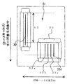
図4はこのような記録ヘッドの顔料インク吐出口列及び染料インク吐出口列を示す模式的正面図であり、同図中、31は吐出口列が形成された吐出口面、32は複数の黒色の顔料インク吐出口を所定ピッチで配列した顔料インク吐出口列、33は各色ごとの複数のカラーの染料インク吐出口を所定ピッチで配列した複数(4列)の染料インク吐出口列を示す。図4に示すような吐出口列の構成によれば、文字などのモノクロ印刷を行う際には顔料インクの黒のみを用いて高速印刷を行い、カラー画像などのカラー印刷は染料インクを用いて高画質で印刷することができる。
FIG. 4 is a schematic front view showing a pigment ink discharge port array and a dye ink discharge port array of such a recording head. In FIG. 4,
また、一方で、顔料インク吐出口列の位置を染料インク吐出口列に対して全体的に列方向にずらして配置することも行われている。図5は顔料インク吐出口列を染料インク吐出口列に対して全体的に列方向にずらして配置した記録ヘッドの吐出口面を示す模式的正面図であり、同図中の符号は前述の図4中の符号に対応しており、それぞれ同じ部分を示す。図5のような吐出口列の配列によれば、先に顔料インクのみによる記録を行い、記録ヘッドの走査1回又は複数回行った後に染料インクによる記録を行うことができる。これにより、記録中の記録媒体を逆搬送することなしに、顔料黒インクを十分に定着させた後に染料カラーインクの印刷を行うことができ、顔料インクと染料インクの記録媒体上での混色や滲みを防ぐことができ、記録画像の画質維持(又は画質向上)を図ることができる。
しかしながら、従来のインクジェット記録装置においては、次のような解決すべき課題があった。すなわち、顔料インク吐出口列と染料インク吐出口列が列方向にずれている記録ヘッドの場合、顔料インクと染料インクを予備吐出受け部で十分に混合させることができず、そのため、染料インクが混ざらない領域において顔料インクの堆積が生じてしまう可能性があった。図4中のL1及び図5中のL2で示す領域が染料インクが届かない顔料インクの吐出領域であり、この領域において顔料インクと染料インクを十分に混合できない。その場合、図6に示すようにプラテン6の近傍に配設された予備吐出受け部5内のインク吸収体57に向けて顔料インクと染料インクの予備吐出を行った場合、染料インク55は染料の性質上インク吸収体57にすぐに吸収されるが、顔料インク54は顔料インクの性質上インク吸収体57上に堆積する可能性がある。顔料インクが堆積すると、前述のように堆積した顔料インクと記録ヘッドが接触する可能性が生じることがある。
However, the conventional inkjet recording apparatus has the following problems to be solved. That is, in the case of a recording head in which the pigment ink discharge port array and the dye ink discharge port array are shifted in the column direction, the pigment ink and the dye ink cannot be sufficiently mixed in the preliminary discharge receiving portion. There is a possibility that the pigment ink may be deposited in an unmixed region. The areas indicated by L1 in FIG. 4 and L2 in FIG. 5 are the pigment ink ejection areas where the dye ink does not reach. In this area, the pigment ink and the dye ink cannot be sufficiently mixed. In that case, as shown in FIG. 6, when the preliminary discharge of the pigment ink and the dye ink is performed toward the ink absorber 57 in the preliminary
本発明はこのような技術的課題に鑑みてなされたものであり、本発明の目的は、顔料インク吐出口列の長さが染料インク吐出口列の長さより大きい記録ヘッドから予備吐出を行う場合でも、予備吐出された顔料インクが予備吐出受け部に堆積することを効率よく低減することができ、記録ヘッドと堆積顔料インクとの接触を防ぐことで良好な画像記録を行うことができるインクジェット記録装置を提供することである。 The present invention has been made in view of such technical problems, and an object of the present invention is to perform preliminary ejection from a recording head in which the length of the pigment ink ejection port array is larger than the length of the dye ink ejection port array However, ink jet recording that can efficiently reduce the pre-discharged pigment ink from being deposited on the pre-discharge receiving portion, and can perform good image recording by preventing contact between the recording head and the accumulated pigment ink. Is to provide a device.
本発明は、上記目的を達成するため、顔料インクを吐出する顔料インク吐出口と染料インクを吐出する染料インク吐出口とを有する記録ヘッドにより記録を行うインクジェット記録装置において、前記吐出口から吐出される記録に寄与しないインクを受ける予備吐出受け部と、前記予備吐出受け部に配された斜面と、を備え、前記染料インク吐出口からのインクを前記斜面の重力方向上流寄りの位置で受け、前記顔料インク吐出口からのインクを前記斜面の重力方向下流寄りの位置で受けることを特徴とする。 In order to achieve the above object, the present invention provides an ink jet recording apparatus that performs recording with a recording head having a pigment ink discharge port for discharging pigment ink and a dye ink discharge port for discharging dye ink. A preliminary discharge receiving portion that receives ink that does not contribute to recording, and a slope arranged in the preliminary discharge receiving portion, and receives ink from the dye ink discharge port at a position upstream of the slope in the gravity direction, The ink from the pigment ink discharge port is received at a position closer to the downstream of the inclined surface in the direction of gravity.
本発明によれば、顔料インク吐出口列の長さが染料インク吐出口列の長さより大きい記録ヘッドから予備吐出を行う場合でも、予備吐出された顔料インクが予備吐出受け部に堆積することを効率よく低減することができ、記録ヘッドと堆積顔料インクとの接触を防ぐことで良好な画像記録を行うことができるインクジェット記録装置が提供される。 According to the present invention, even when preliminary ejection is performed from a recording head in which the length of the pigment ink ejection port array is longer than the length of the dye ink ejection port array, the preliminarily ejected pigment ink is deposited on the preliminary ejection receiver. There is provided an ink jet recording apparatus which can be efficiently reduced and can perform good image recording by preventing contact between the recording head and the deposited pigment ink.
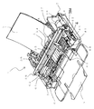
以下、図面を参照して本発明の実施形態を具体的に説明する。なお、各図面を通して同一符号は同一又は対応部分を示すものである。図1は本発明の一実施形態に係るインクジェット記録装置の主要部を示す模式的斜視図であり、図2は本発明の第1の実施形態に係るインクジェット記録装置の予備吐出受け部と予備吐出位置を示す模式的部分斜視図である。図1及び図2において、インクジェット記録装置1は、部分的に示す装置本体のベース(又はシャーシ)7と、記録紙やプラスチックシート等の記録媒体2を積載するとともに記録媒体2を1枚ずつ分離して給送するための給紙部8と、記録部を通して記録媒体2を搬送する搬送ローラ61と、記録部において記録媒体2を支持するプラテン6と、プラテン6と対向して配置され記録媒体2にインクを吐出して記録を行う記録ヘッド3と、記録ヘッド3のインク吐出機能を正常な状態に維持回復するための回復機構部4と、記録後の記録媒体2を積載する排紙トレイ9と、を備えている。
Embodiments of the present invention will be specifically described below with reference to the drawings. Note that the same reference numerals denote the same or corresponding parts throughout the drawings. FIG. 1 is a schematic perspective view showing a main part of an ink jet recording apparatus according to an embodiment of the present invention, and FIG. 2 is a preliminary discharge receiving section and a preliminary discharge of the ink jet recording apparatus according to the first embodiment of the present invention. It is a typical fragmentary perspective view which shows a position. 1 and 2, an ink
記録ヘッド3は記録情報に基づいて吐出口から記録媒体2へインクを吐出して記録を行うものである。図4は記録ヘッドの吐出口面における吐出口の配列状態の一例を示す模式図であり、図5は記録ヘッドの吐出口面における吐出口の配列状態の別の例を示す模式図である。次に、記録ヘッド3等からなる記録手段について説明する。図1及び図2並びに図4及び図5において、記録ヘッド3は往復移動可能なキャリッジ34に搭載されている。また、記録ヘッド3には交換可能なインクタンク35が装着されており、記録ヘッド3のプラテン6と対向する側には、吐出口(本実施形態では、複数の吐出口を所定ピッチで配列した吐出口列)が形成された吐出口面31が構成されている。
The
本実施形態では、吐出口面31に、1列の顔料インク吐出口列32と4列の染料インク吐出口列33a、33b、33c、33dが形成されている。顔料インク吐出口列32は記録媒体搬送方向に所定ピッチで配列された複数のブラックの顔料インク吐出口で構成され、各染料インク吐出口列33のそれぞれは記録媒体搬送方向に所定ピッチで配列された複数のカラーの染料インク吐出口で構成されている。4列の各染料インク吐出口列33(33a、33b、33c、33d)から吐出される液体としては、例えば、イエローインク、マゼンタインク、シアンインク、処理液などが使用される。そして、ブラックの顔料インク吐出口列32は、カラーの各染料インク吐出口列33より長い吐出口列で構成されている。
In the present embodiment, a single row of pigment
図4の吐出口面31においては、顔料インク吐出口列32は、各染料インク吐出口列33に対して、記録媒体搬送方向下流側端を揃えるとともに記録媒体搬送方向の上流側に長さL1だけ長くなるように位置をずらして形成されている。また、図5の吐出口面31においては、顔料インク吐出口列32は、各染料インク吐出口列33に対して、全体的に搬送方向上流へ位置をずらして配置されており、搬送方向上流側への進出長さL2は図4の場合の進出長さL1よりさらに長くなっている。
In the
図1において、記録ヘッド3を搭載したキャリッジ34は、装置本体に設置されたガイドシャフト36に沿って主走査方向に往復移動可能に案内支持されている。シャーシ7の一端部に取り付けられたキャリッジモータ38にはモータプーリ38aが設けられ、このモータプーリ38aとその反対側に配置されたアイドラプーリ39との間に張架されたタイミングベルト37の一部がキャリッジ34に連結されている。従って、キャリッジモータ38の回転及び回転方向を制御することにより、記録ヘッド3による主走査方向の位置及び移動が制御される。
In FIG. 1, a
搬送ローラ61に対してはピンチローラ62が不図示のピンチローラばねの付勢力によって押圧されており、該ピンチローラ62が搬送ローラ61の回転に従動回転することで記録媒体2に対する搬送力を発生させている。排紙ローラ63には不図示の拍車が不図示のばね軸の付勢力によって押圧されており、この拍車が排紙ローラ63の回転に従動回転することで記録用紙2に対する搬送力を発生させている。
A pinch roller 62 is pressed against the
上記構成のインクジェット記録装置においては、給紙部8から1枚ずつ分離されて給送された記録媒体2は、搬送ローラ61とピンチローラ62まで搬送された後、不図示の搬送モータで回転駆動される搬送ローラ61によりプラテン6上の記録開始位置まで搬送される。そして、キャリッジモータ38によりタイミングベルト37を介してキャリッジ34を移動させることにより、記録ヘッド3で記録媒体2上を往復走査しながら、所定の画像情報に基づいて記録ヘッド3の吐出口からインクを記録媒体2上の所定位置に吐出することで画像記録が行われる。
In the ink jet recording apparatus having the above configuration, the
記録ヘッド3の1ライン分の記録走査が終わると、搬送ローラ61を再び回転させて記録媒体2を次のラインの記録開始位置までピッチ送りし、記録ヘッド3の主走査によって次のラインの画像記録が行われる。以上の記録動作を所定の画像情報に基づいて所定回数繰り返し、記録媒体2に対する記録が終了すると、記録媒体2は排紙ローラ63の回転により装置本体外へ排出され、排紙トレイ9に積載される。
When the recording scan for one line of the
記録ヘッド3の、吐出口列32、33のインク吐出部は、複数の微細な吐出口、各吐出口に対応する液路、各液路の一部に設けられるエネルギー作用部、並びに各エネルギー作用部に設けられてインクに液滴形成エネルギーを付与するためのエネルギー発生手段などで構成されている。このエネルギー発生手段としては、ピエゾ素子等の電気機械変換体を用いる手段、レーザー等の電磁波を照射して発熱させてその熱による作用で液滴を吐出する手段、あるいは、発熱抵抗体を有する発熱素子等の電気熱変換体によって液体を加熱して吐出させる手段などが使用される。
The ink ejection units of the
そのうち、熱エネルギーにより液体を吐出させるインクジェット記録ヘッドは、吐出液滴を形成するための吐出口を高密度で配列することができ、高解像度の画像を記録することができる。その中でも、電気熱変換体をエネルギー発生手段として用いる記録ヘッドは、小型化が容易であり、かつ最近の半導体分野における技術の進歩と信頼性の向上が著しいIC技術やマイクロ加工技術の長所を十分に活用でき、高密度実装が容易で、製造コストも安価なことから有利である。 Among them, an ink jet recording head that discharges liquid by thermal energy can arrange discharge ports for forming discharged droplets at high density, and can record a high-resolution image. Among them, recording heads that use electrothermal transducers as energy generation means are easy to miniaturize and have the advantages of IC technology and micromachining technology that have made significant progress in technology and reliability in recent semiconductor fields. It is advantageous in that it can be used for high-density mounting, and high-density mounting is easy and the manufacturing cost is low.
次に、記録ヘッド3のインク吐出機能を維持回復するための回復機構部4について説明する。記録ヘッド3の吐出口を覆うためのキャッピング手段44は、顔料インク吐出口列32用のキャップ42と染料インク吐出口列用のキャップ43とを備えている。キャッピング手段44は、記録ヘッド3の移動範囲内であって、記録のための主走査範囲(記録領域)を外れた位置であって、記録ヘッド3が対向位置にあるときに吐出口面31の吐出口を密閉できる位置に配設されている。各キャップ42、43は、一般にゴムなどの弾性材料で形成され、対応する吐出口列32、33を密閉開放するためにキャッピング手段44の駆動によって吐出口面31に密着離間されるように構成されている。
Next, the
前記キャッピング手段44は、記録していないときに顔料インク吐出口列32及び染料インク吐出口列33を保護したり、吐出口からのインクの蒸発を低減したり、加圧回復もしくは吸引回復の処理を行うために用いられる。すなわち、吐出回復処理の一つとして、各吐出口列32、33をキャップ42、43で覆った状態で、これらのキャップに接続されたポンプ41を作動させて吐出口内のインクを強制的に吸引することにより、吐出口内のインクをリフレッシュすることで吐出不良要因を除去する吸引回復処理が行われている。
The capping
また、上記の吸引回復処理の他に、予備吐出による回復処理が行われている。この予備吐出は、記録ヘッド3の主走査方向の移動範囲内に図2(又は図3)に示すような予備吐出受け部(吐出インク受け部)5を設け、記録ヘッド3の各吐出口列32、33を予備吐出受け部5に対向させた状態で該記録ヘッド3を駆動することにより記録に寄与しないインク吐出を行うものである。この予備吐出処理によっても、上記の吸引回復の場合と同様、各吐出口の内部の気泡や塵埃、さらには増粘して記録に適さなくなったインクなどの吐出不良要因を除去することで、記録ヘッドのインク吐出機能を正常な状態に維持回復することができる。
In addition to the above-described suction recovery process, a recovery process by preliminary discharge is performed. In this preliminary ejection, a preliminary ejection receiving portion (ejection ink receiving portion) 5 as shown in FIG. 2 (or FIG. 3) is provided within the movement range of the
上記ポンプ41は、インクの強制吸引のために吸引力を作用させるために使用される他に、強制吸引を用いる上記吸引回復処理や上記予備吐出処理などの吐出回復処理に際して、キャップ44内に受容された(又は残留する)廃インクを吸引して回収するために使用される。本実施形態では、ポンプ41として、例えば、不図示のコロによって不図示のチューブを押しつぶして負圧を発生させるチューブポンプ、あるいはピストン・シリンダ式のポンプなどを使用することができる。また、上記吸引回復処理や上記予備吐出処理によって生じた不要インク(廃インク)を受容し回収するための廃インク吸収体(不図示)がプラテン6の下側に配設されている。
The pump 41 is used for forced suction of ink and is received in the
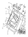
そこで、回復機構部4と対向する反対側の位置であってプラテン6の隣接位置に、図2に示すような予備吐出受け部5が配設されている。本実施形態では、予備吐出受け部5はプラテン6と一体に構成されており、この予備吐出受け部5には、記録媒体2の搬送方向下流側に斜面上流部51aを有するとともに搬送方向上流側に斜面下流部51bを有する斜面51が形成されている。前記斜面下流部51bには、プラテン6の下側に配置された不図示の廃インク吸収体に連通する孔又は開口51cが形成されている。そして、この予備吐出受け部5は、予備吐出に際して、染料インク吐出口33からのインクを斜面51の重力方向上流寄りの位置である斜面上流部51aで受け、顔料インク吐出口32からのインクを斜面51の重力方向下流寄りの位置である斜面下流部51bで受けるように構成されている。
Therefore, a preliminary
次に、上記予備吐出受け部5の詳細な構成並びに該予備吐出受け部における予備吐出動作について説明する。図4又は図5に示すように顔料インク吐出口列32と染料インク吐出口列33を互いに位置をずらして配置されている場合、予備吐出受け部5に向けて予備吐出を行った際には、図2に示すように、斜面51の斜面上流部51a寄りの位置に予備吐出された染料インク53が付着し、斜面下流部51b寄りの位置に予備吐出された顔料インク52が付着するように構成されている。予備吐出された染料インク53は、その性質上堆積しにくくかつ流れやすいので、斜面上流部51aに付着した後、早期にその大部分が斜面下流部51bへ向かって流れていく。
Next, the detailed configuration of the preliminary
染料インク53が流れる領域には予備吐出された顔料インク52が付着しており、従ってこの顔料インク52は流れてくる染料インク53と混合される。顔料インク52自身はその性質上堆積しやすいが、染料インク53と混合される前記顔料インク52は、混合されることで堆積しにくくかつ流れやすい性質となり、染料インク53と共に斜面下流部51bにある孔51cを通してプラテン6の下側の廃インク吸収体へと流れていき、該廃インク吸収体内に吸収されて回収される。
The preliminarily ejected pigment ink 52 adheres to the region where the dye ink 53 flows, and thus the pigment ink 52 is mixed with the flowing dye ink 53. The pigment ink 52 itself is easy to deposit due to its properties, but the pigment ink 52 mixed with the dye ink 53 is not easily deposited and easily flows when mixed, and is located in the sloped downstream portion 51 b together with the dye ink 53. It flows to the waste ink absorber below the
予備吐出に使用するインク量については、顔料インクの吐出量よりも染料インクの吐出量を多くすることにより、混合インク中の染料インクの割合を多くし、一層堆積しにくく流れやすい混合インクにすることができ、顔料インクの堆積を一層効果的に低減(又は阻止)することができる。さらに、顔料インクの予備吐出を行うより前にあらかじめ染料インクの予備吐出を行っておくことで、染料インクが斜面下流部51bに到達した後に顔料インクの吐出を行うようにし、それによって、一層確実に顔料インクと染料インクを混合させて確実に流れやすい混合インクを作ることが可能になり、インクの堆積を一層効果的に防止することができる。 As for the amount of ink used for preliminary ejection, by increasing the amount of dye ink ejected more than the amount of pigment ink ejected, the proportion of dye ink in the mixed ink is increased to make the mixed ink more difficult to deposit and flow easily. And can more effectively reduce (or prevent) the deposition of pigment ink. Further, by preliminarily discharging the dye ink prior to the preliminary discharge of the pigment ink, the pigment ink is discharged after the dye ink reaches the slope downstream portion 51b, thereby further reliably. It is possible to mix the pigment ink and the dye ink with each other to make a mixed ink that can surely flow easily, and to prevent the ink from being deposited more effectively.
また、本実施形態では、記録ヘッド3の走査方向の移動経路における顔料インクの予備吐出位置52と染料インクの予備吐出位置53は図2に示すように互いに重なるような同じ位置に選定されている。このように予備吐出位置を同じにすることにより、顔料インクと染料インクを一層確実に混合させることができる。また、本実施形態のように複数の染料インク吐出口列33を有する場合には、各染料インクの予備吐出位置53を各色の吐出口列ごとに個別に制御することにより、後述する図3で示すように、全ての染料インクの記録ヘッド移動方向における予備吐出位置53を顔料の予備吐出位置52に重ね合わせることもできる。このように1つの位置に重ねることで、一層確実に顔料インクと染料インクを混合させて確実に流れやすい混合インクを作ることが可能になり、インクの堆積を一層効果的に防止することができる。
Further, in the present embodiment, the pigment ink preliminary discharge position 52 and the dye ink preliminary discharge position 53 in the movement path in the scanning direction of the
以上説明した本発明の実施形態によれば、安価な構成で記録装置の大型化を招くことなく、顔料インク吐出口列の長さが染料インク吐出口列の長さより大きい記録ヘッドから予備吐出を行う場合でも、予備吐出された顔料インクが予備吐出受け部に堆積することを効率よく低減することができ、記録ヘッドと堆積顔料インクとの接触を防ぐことで良好な画像記録を行うことができるインクジェット記録装置が提供される。 According to the embodiment of the present invention described above, preliminary ejection is performed from a recording head in which the length of the pigment ink ejection port array is larger than the length of the dye ink ejection port array without increasing the size of the recording apparatus with an inexpensive configuration. Even when it is performed, it is possible to efficiently reduce the pre-discharged pigment ink from being deposited on the pre-discharge receiving portion, and it is possible to perform good image recording by preventing contact between the recording head and the accumulated pigment ink. An ink jet recording apparatus is provided.
図3は本発明の第2の実施形態に係るインクジェット記録装置の予備吐出受け部5と予備吐出位置を示す模式的部分斜視図である。前述した第1の実施形態では予備吐出受け部5及びその斜面51をプラテン6と一体に構成したが、図3のように別部材で構成しても良い。本実施形態では、斜面51を有するインク受容面がフィルム状の別部品で構成されている。プラテン6に隣接して設けられた予備吐出受け部5にフィルムなどの別部材56を嵌めることにより、第1の実施形態と同様の斜面51が形成されている。この別部材56の斜面51も、記録媒体2の搬送方向下流側に斜面上流部51aを有するとともに搬送方向上流側に斜面下流部51bを有する斜面で構成されている。
FIG. 3 is a schematic partial perspective view showing the preliminary
そして、予備吐出に際して、染料インク吐出口33からのインクを斜面51の重力方向上流寄りの位置である斜面上流部51aで受け、顔料インク吐出口32からのインクを斜面51の重力方向下流寄りの位置である斜面下流部51bで受けるように構成されている。また、斜面51を有する別部材56の下側には予備吐出インクを吸収するための多孔質体からなるインク吸収体57が配置されており、このインク吸収体57は斜面下流部51bに形成された孔又は開口51cと接触している。このインク吸収体57の直下にはプラテン6の下側に配置された前述の廃インク吸収体が配設されている。
In the preliminary ejection, the ink from the dye ink ejection port 33 is received by the slope upstream portion 51a, which is the position upstream of the
以上のような図3に示す構成において、フィルム等の別部材56の斜面下流部51bに予備吐出される顔料インク52は、同じく別部材56等の斜面上流部51aに予備吐出され付着した後に流下してくる染料インク53と混合される。そして、混合されたインクは斜面下流部51bに形成された孔又は開口51cへ向かって流れていき、第1の実施形態と同様、顔料インク52の堆積を低減又は防止する効果が得られる。さらに、斜面下流部51bの孔又は開口51cを通過した混合インクは、予備吐出受け部5内のインク吸収体57に一旦吸収され一時的に収容される。収容された混合インクがある一定量を超えると、このインクはインク吸収体57からその下側に配置された不図示の前記廃インク吸収体へと伝わっていき、該廃インク吸収体内に吸収されて回収される。
In the configuration shown in FIG. 3 as described above, the pigment ink 52 preliminarily discharged to the slope downstream portion 51b of another member 56 such as a film flows down after being preliminarily discharged and attached to the slope upstream portion 51a of the other member 56 or the like. The dye ink 53 is mixed. Then, the mixed ink flows toward the hole or
その際、インク吸収体57にあらかじめグリセリンなどの親水性のよい物質を含有させておくことにより、インク吸収体57内部でのインクの浸透性を向上させることができ、予備吐出インクを一層スムーズに前記廃インク吸収体へ導くことができる。
図3の第2の実施形態はその他の点では前述の第1の実施形態と実質的に同じ構成を有しており、その他の点についての説明は省略する。従って、第2の実施形態によっても、前述の第1の実施形態の場合と同様の作用効果を奏することができる。
At that time, by preliminarily containing a good hydrophilic substance such as glycerin in the
The second embodiment of FIG. 3 has substantially the same configuration as the first embodiment described above in other respects, and the description of the other points is omitted. Therefore, according to the second embodiment, the same operational effects as those of the first embodiment can be obtained.
なお、以上の実施形態では、1本の比較的長い顔料インク吐出口列32と4本の比較的短い染料インク吐出口列33を有する記録ヘッド3を例に挙げて説明したが、本発明は、顔料インク吐出口と染料インク吐出口を用いるインクジェット記録装置であれば、吐出口の配置や、インク色の数や、吐出口列の長さなどに関係なく適用可能なものであり、同様の作用効果を奏するものである。また、本発明は、インクジェット記録装置であれば、単色又は複数色で記録する1個の記録ヘッドを用いる記録装置、異なる色のインクで記録する複数の記録ヘッドを用いるカラー記録装置、あるいは同一色彩で異なる濃度で記録する複数の記録ヘッドを用いる階調記録装置、さらには、これらを組み合わせた記録装置の場合にも、同様に適用することができ、同様の効果を達成し得るものである。
In the above embodiment, the
さらに、本発明は、記録ヘッドとインクタンクを一体化した交換可能なインクカートリッジを用いる構成、記録ヘッドとインクタンクを別体にし、その間をインク供給用チューブ等で接続する構成など、記録ヘッドとインクタンクの配置構成がどのような場合にも同様に適用することができ、同様の効果が得られるものである。 Furthermore, the present invention relates to a recording head including a configuration using a replaceable ink cartridge in which a recording head and an ink tank are integrated, a configuration in which the recording head and the ink tank are separated, and a connection between them using an ink supply tube or the like. The present invention can be similarly applied to any arrangement of the ink tank, and the same effect can be obtained.
1 インクジェット記録装置
2 記録媒体
3 記録ヘッド
31 吐出口面
32 顔料インク吐出口(顔料インク吐出口列)
33 染料インク吐出口(染料インク吐出口列)
34 キャリッジ
35 インクタンク
36 ガイドシャフト
37 タイミングベルト
38 キャリッジモータ
4 回復機構部
41 ポンプ
42 顔料インク吐出口列のキャップ
43 染料インク吐出口列のキャップ
44 キャッピング手段
5 予備吐出受け部
51 斜面
51a 斜面上流部(重力方向の上流寄り)
51b 斜面下流部(重力方向の下流寄り)
51c 孔又は開口
52 予備吐出された顔料インク及びその吐出位置
53 予備吐出された染料インク及びその吐出位置
56 フィルム等の別部材
57 インク吸収体
6 プラテン
61 搬送ローラ
62 ピンチローラ
63 排紙ローラ
8 給紙部
9 排紙トレイ
DESCRIPTION OF
33 Dye ink discharge port (Dye ink discharge port array)
34 Carriage 35
51b Downstream part of the slope (downstream in the gravity direction)
51c Hole or opening 52 Preliminarily ejected pigment ink and its ejection position 53 Preliminarily ejected dye ink and its ejection position 56 Another member such as
Claims (8)
前記吐出口から吐出される記録に寄与しないインクを受ける予備吐出受け部と、
前記予備吐出受け部に配された斜面と、
を備え、前記染料インク吐出口からのインクを前記斜面の重力方向上流寄りの位置で受け、前記顔料インク吐出口からのインクを前記斜面の重力方向下流寄りの位置で受けることを特徴とするインクジェット記録装置。 In an ink jet recording apparatus that performs recording by a recording head having a pigment ink discharge port for discharging pigment ink and a dye ink discharge port for discharging dye ink,
A preliminary discharge receiving portion that receives ink that does not contribute to recording discharged from the discharge port;
A slope arranged in the preliminary discharge receiver,
An ink jet printing apparatus that receives ink from the dye ink discharge port at a position upstream of the inclined surface in the gravity direction and receives ink from the pigment ink discharge port at a position downstream of the inclined surface in the gravity direction. Recording device.
Priority Applications (3)
| Application Number | Priority Date | Filing Date | Title |
|---|---|---|---|
| JP2004222753A JP2006035786A (en) | 2004-07-30 | 2004-07-30 | Ink-jet recorder |
| US11/188,631 US7396105B2 (en) | 2004-07-30 | 2005-07-26 | Ink jet recording apparatus |
| US12/131,402 US7926905B2 (en) | 2004-07-30 | 2008-06-02 | Ink jet recording apparatus |
Applications Claiming Priority (1)
| Application Number | Priority Date | Filing Date | Title |
|---|---|---|---|
| JP2004222753A JP2006035786A (en) | 2004-07-30 | 2004-07-30 | Ink-jet recorder |
Publications (2)
| Publication Number | Publication Date |
|---|---|
| JP2006035786A true JP2006035786A (en) | 2006-02-09 |
| JP2006035786A5 JP2006035786A5 (en) | 2007-09-13 |
Family
ID=35731641
Family Applications (1)
| Application Number | Title | Priority Date | Filing Date |
|---|---|---|---|
| JP2004222753A Withdrawn JP2006035786A (en) | 2004-07-30 | 2004-07-30 | Ink-jet recorder |
Country Status (2)
| Country | Link |
|---|---|
| US (2) | US7396105B2 (en) |
| JP (1) | JP2006035786A (en) |
Cited By (2)
| Publication number | Priority date | Publication date | Assignee | Title |
|---|---|---|---|---|
| JP2011051105A (en) * | 2009-08-31 | 2011-03-17 | Brother Industries Ltd | Liquid discharge device |
| JP2019014150A (en) * | 2017-07-07 | 2019-01-31 | キヤノン株式会社 | Inkjet recording device |
Families Citing this family (5)
| Publication number | Priority date | Publication date | Assignee | Title |
|---|---|---|---|---|
| KR101200413B1 (en) * | 2007-06-21 | 2012-11-13 | 삼성전자주식회사 | Waste ink container, waste ink storing apparatus and ink jet printer including the same |
| JP2012016820A (en) * | 2010-07-06 | 2012-01-26 | Ricoh Co Ltd | Image forming apparatus and image forming method |
| JP2012045778A (en) * | 2010-08-25 | 2012-03-08 | Sony Corp | Liquid discharging apparatus and liquid discharging head |
| JP6331759B2 (en) * | 2014-06-26 | 2018-05-30 | セイコーエプソン株式会社 | Inkjet printer |
| US10349116B2 (en) * | 2014-12-29 | 2019-07-09 | DISH Technologies L.L.C. | Systems and methods for pre-caching media content in response to user-system interaction |
Family Cites Families (6)
| Publication number | Priority date | Publication date | Assignee | Title |
|---|---|---|---|---|
| DE69417293T2 (en) * | 1993-06-25 | 1999-10-14 | Canon Kk | Ink jet recorder |
| US5936647A (en) * | 1996-10-31 | 1999-08-10 | Hewlett-Packard Company | Flexible frame onsert capping of inkjet printheads |
| US6050671A (en) * | 1997-10-27 | 2000-04-18 | Hewlett-Packard Company | Stalagmite dissolving spittoon system for inkjet printheads |
| US6619783B2 (en) * | 1998-11-20 | 2003-09-16 | Seiko Epson Corp | Flushing position controller incorporated in ink-jet recording apparatus and flushing method used for the same |
| US6752494B2 (en) * | 2001-02-27 | 2004-06-22 | Canon Kabushiki Kaisha | Ink-jet recording apparatus and ink-jet recording process |
| JP2003053986A (en) | 2001-08-10 | 2003-02-26 | Canon Inc | Ink jet recorder |
-
2004
- 2004-07-30 JP JP2004222753A patent/JP2006035786A/en not_active Withdrawn
-
2005
- 2005-07-26 US US11/188,631 patent/US7396105B2/en not_active Expired - Fee Related
-
2008
- 2008-06-02 US US12/131,402 patent/US7926905B2/en not_active Expired - Fee Related
Cited By (3)
| Publication number | Priority date | Publication date | Assignee | Title |
|---|---|---|---|---|
| JP2011051105A (en) * | 2009-08-31 | 2011-03-17 | Brother Industries Ltd | Liquid discharge device |
| US8398189B2 (en) | 2009-08-31 | 2013-03-19 | Brother Kogyo Kabushiki Kaisha | Liquid discharge apparatus |
| JP2019014150A (en) * | 2017-07-07 | 2019-01-31 | キヤノン株式会社 | Inkjet recording device |
Also Published As
| Publication number | Publication date |
|---|---|
| US7926905B2 (en) | 2011-04-19 |
| US20060023022A1 (en) | 2006-02-02 |
| US7396105B2 (en) | 2008-07-08 |
| US20080231659A1 (en) | 2008-09-25 |
Similar Documents
| Publication | Publication Date | Title |
|---|---|---|
| JP4948146B2 (en) | Inkjet recording device | |
| US7926905B2 (en) | Ink jet recording apparatus | |
| JP2007160549A (en) | Inkjet recorder | |
| JP3100451B2 (en) | Ink jet recording device | |
| JP2007253471A (en) | Waste ink container | |
| JPH11348313A (en) | Ink-jet printing apparatus and ink-jet print method | |
| JPH06328731A (en) | Ink jet recording device | |
| JP4455901B2 (en) | Droplet discharge head, liquid cartridge, and droplet discharge apparatus using the same | |
| JP2004142280A (en) | Inkjet recording device | |
| JP2000238293A (en) | Ink jet printer | |
| JP3059312B2 (en) | Recording head, recording cartridge and recording device | |
| JP2004106433A (en) | Inkjet recorder | |
| JP2005131791A (en) | Ink jet head and ink jet recorder | |
| JP4624042B2 (en) | Inkjet head manufacturing method | |
| JP2000185414A (en) | Ink jet recording apparatus | |
| JPH09262975A (en) | Ink-jet recording device | |
| JP2005111690A (en) | Cap for inkjet recording head, and inkjet recording apparatus | |
| JP2005028741A (en) | Method of recovering for inkjet recording means | |
| JPH1076648A (en) | Ink jet recording head and ink jet recording method | |
| JP2004042446A (en) | Ink jet recording apparatus | |
| JP2005111686A (en) | Inkjet recording apparatus | |
| JP2878001B2 (en) | Ink jet recording device | |
| JP2004314319A (en) | Liquid injection device | |
| JP3053676B2 (en) | Ink jet recording device | |
| JP2007144698A (en) | Inkjet recording device |
Legal Events
| Date | Code | Title | Description |
|---|---|---|---|
| RD04 | Notification of resignation of power of attorney |
Free format text: JAPANESE INTERMEDIATE CODE: A7424 Effective date: 20060629 |
|
| A521 | Request for written amendment filed |
Free format text: JAPANESE INTERMEDIATE CODE: A523 Effective date: 20070726 |
|
| A621 | Written request for application examination |
Free format text: JAPANESE INTERMEDIATE CODE: A621 Effective date: 20070726 |
|
| A761 | Written withdrawal of application |
Free format text: JAPANESE INTERMEDIATE CODE: A761 Effective date: 20080125 |