JP2006033196A - Color correcting device, image-forming device, color correction method, color correcting program, and computer-readable recording medium - Google Patents
Color correcting device, image-forming device, color correction method, color correcting program, and computer-readable recording medium Download PDFInfo
- Publication number
- JP2006033196A JP2006033196A JP2004206443A JP2004206443A JP2006033196A JP 2006033196 A JP2006033196 A JP 2006033196A JP 2004206443 A JP2004206443 A JP 2004206443A JP 2004206443 A JP2004206443 A JP 2004206443A JP 2006033196 A JP2006033196 A JP 2006033196A
- Authority
- JP
- Japan
- Prior art keywords
- color
- modified
- area
- correction
- color correction
- Prior art date
- Legal status (The legal status is an assumption and is not a legal conclusion. Google has not performed a legal analysis and makes no representation as to the accuracy of the status listed.)
- Pending
Links
Images


Landscapes
- Color Image Communication Systems (AREA)
- Facsimile Image Signal Circuits (AREA)
Abstract
Description
本発明は、デジタルカラー複写機等のデジタルカラー画像形成装置やカラーマネージメントシステム等で使用される色補正テーブルを修整するための色修整装置に関するものである。 The present invention relates to a color correction apparatus for correcting a color correction table used in a digital color image forming apparatus such as a digital color copying machine or a color management system.
一般にプリンタやデジタル複写機などの画像形成装置の色変換システムを構築するには、均等色空間上の色座標値が既知の色票(パッチ)を出力し、その測色値と色座標値とを元に、画像形成装置の色再現特性をニューラルネットワークやICC(International Color Consortium)プロファイル生成ツールによりモデリングし、3次元のルックアップテーブル(LUT:Look Up Table)を作成している。 In general, in order to construct a color conversion system for an image forming apparatus such as a printer or a digital copying machine, a color chart (patch) having a known color coordinate value in a uniform color space is output, and its colorimetric value, color coordinate value, Based on the above, the color reproduction characteristics of the image forming apparatus are modeled by a neural network or an ICC (International Color Consortium) profile generation tool to create a three-dimensional look-up table (LUT).
しかしながら、出力画像データが書き込まれているLUTを参照することにより入力画像データを一義的に色変換していることや、デバイスの色再現特性が非常に複雑であることから、所望の色再現性が得られない場合がある。 However, since the input image data is uniquely color-converted by referring to the LUT in which the output image data is written, and the color reproduction characteristics of the device are very complex, the desired color reproducibility May not be obtained.
そこで、所望の色再現画像を実現するため、再現された色の一部を任意に変更する必要がある。さらに、色彩や明度を忠実に再現するだけでなく、ユーザーの好みに合った色再現や、記憶色に基づいた色再現を行う上で、再現された色の一部を任意に変更する必要もある。しかし、自由に、かつ、的確に色修整し、所望の色の再現画像を得るのは困難である。 Therefore, in order to realize a desired color reproduction image, it is necessary to arbitrarily change a part of the reproduced color. In addition to faithfully reproducing color and lightness, it is also necessary to change part of the reproduced color arbitrarily when performing color reproduction that matches the user's preference and color reproduction based on the memory color. is there. However, it is difficult to correct the color freely and accurately and obtain a reproduction image of a desired color.
まず、カラー印刷を行う際に、画面表示の基本となる3色であるR(赤)・G(緑)・B(青)のR、G、Bの値のそれぞれ、または画像印刷時に使用する色材の基本となる4色であるC(シアン)・M(マゼンタ)・Y(イエロー)・K(ブラック)のC、M、Y、Kの値それぞれのいずれかをユーザーが変更することで、印刷される色を微調整する方法がある。しかしながら、この方法では調整に使用するRGBの値またはCMYKの値が、人間の色彩感覚とは必ずしも対応しないため、ユーザーが特定の色を別の色に微調整したい場合などは、RGBまたはCMYKの値を複雑に調整しなければならず、なかなか期待するような色の微調整を実現することが難しい。 First, when performing color printing, R (red), G (green), and B (blue), which are the three basic colors for screen display, R, G, and B values are used, or when printing an image. By changing any of the C, M, Y, and K values of C (cyan), M (magenta), Y (yellow), and K (black), which are the four basic colors of the color material, There is a method for finely adjusting the color to be printed. However, in this method, the RGB value or CMYK value used for adjustment does not necessarily correspond to the human color sensation. Therefore, when the user wants to finely adjust a specific color to another color, RGB or CMYK The value has to be adjusted in a complicated manner, and it is difficult to achieve fine color adjustments as expected.
また、上記のような再現色の一部を調整する場合、調整の度合いが大きいと、調整した領域と調整しなかった領域との境界における色彩の移り変わりに差が生じ、本来の画像には存在しない輪郭が存在するかのように見えてしまう異常な現象(擬似輪郭)が発生する。それらの問題点を改善するために、たとえば、以下の特許文献1や特許文献2に記載された技術が提案されている。
In addition, when adjusting a part of the reproduced color as described above, if the degree of adjustment is large, there will be a difference in the color transition at the boundary between the adjusted area and the unadjusted area, and it will exist in the original image. An abnormal phenomenon (pseudo contour) that appears as if there is a contour that does not occur occurs. In order to improve these problems, for example, techniques described in
特許文献1に記載の技術では、どのように色彩調整をすべきかの指針を特定するための調整基準となる指定色及びそれに対応する調整色を設定する。そして、被調整色が、指定色と同一の色彩であれば、それに対応する調整色に調整する。また、被調整色が指定色と同一でない色彩であっても、それら指定色及び調整色による調整基準を受けた色彩に調整する。
In the technique described in
また、特許文献2に記載の技術では、画像データに対して、ユーザーが希望する色との違いを確認し、修整前の色と修整後の色、および修整が及ぼす範囲を指定する修整操作を加えることにより、補正に必要な補正量を求め、該補正量により上記色変換用テーブルを修整する。
In the technique described in
いずれの文献に記載された技術においても、指定色と調整色、または修整前と修整後の色とを1対1の対応関係で設定することにより色彩を調整している。
しかしながら、実際に再現する色は、ある程度の色の範囲を有しているので、上記文献に記載された技術では所望の色再現を実現するには不十分である。すなわち、色再現性は、製品ごとやその装置自体の経年変化によって一定でないことが多い。したがって、指定色と調整色、または修整前と修整後の色とを1対1の対応関係で設定するだけでは、その色再現性の変化に対応しきれない。 However, since the colors that are actually reproduced have a certain range of colors, the technique described in the above document is insufficient to achieve the desired color reproduction. That is, the color reproducibility is often not constant due to the aging of each product or the device itself. Therefore, it is not possible to cope with the change in the color reproducibility by simply setting the designated color and the adjustment color or the color before and after the correction in a one-to-one correspondence relationship.
なお、いずれの従来技術においても、複数の点を指定色または調整色として設定することにより、再現する色にある程度の範囲を持たせることはできるものの、そのように指定色または調整色を設定することは、効率が悪く容易ではない。 In any of the prior arts, by setting a plurality of points as designated colors or adjustment colors, the reproduced color can have a certain range, but the designated color or adjustment color is set as such. It is not easy and inefficient.
本発明は、上記従来の問題点に鑑みなされたものであって、色再現の精度を向上させることができる色修整装置、画像形成装置、色修整方法、色修整プログラム、およびコンピュータ読み取り可能な記録媒体を提供することを目的とする。 The present invention has been made in view of the above-described conventional problems, and is a color correction device, an image forming apparatus, a color correction method, a color correction program, and a computer-readable recording capable of improving the accuracy of color reproduction. The purpose is to provide a medium.
本発明の色修整装置は、上記課題を解決するために、複数の色成分よりなる第1の表色系の画像データを第2の表色系の画像データに変換するための色補正テーブルを生成するものであって、色修整の対象とする修整色と同じ色修整が行われる色空間内の領域を修整色領域として設定する修整色領域設定手段と、色修整の影響が及ぼされる色空間内の領域を修整周辺領域として設定する修整周辺領域設定手段と、上記修整色領域を上記修整周辺領域内で移動させて得られる修整周辺領域内の色を、色修整後の色に設定して、上記色補正テーブルを生成する色補正テーブル生成手段とを備えていることを特徴としている。 In order to solve the above problems, a color correction apparatus according to the present invention has a color correction table for converting image data of a first color system composed of a plurality of color components into image data of a second color system. A color space setting means for setting an area in a color space that is generated and that is subjected to the same color correction as the target color to be corrected as a corrected color area, and a color space that is affected by the color correction A modified peripheral area setting means for setting the inner area as the modified peripheral area, and the color in the modified peripheral area obtained by moving the modified color area in the modified peripheral area is set to the color after the color modification. And a color correction table generating means for generating the color correction table.
また、本発明の色修整方法は、複数の色成分よりなる第1の表色系の画像データを第2の表色系の画像データに変換するための色補正テーブルを生成する方法であって、色修整の対象とする修整色と同じ色修整が行われる色空間内の領域を修整色領域として設定する第1ステップと、色修整の影響が及ぼされる色空間内の領域を修整周辺領域として設定する第2ステップと、上記修整色領域を上記修整周辺領域内で移動させて得られる修整周辺領域内の色を、色修整後の色に設定して、上記色補正テーブルを生成する第3ステップとを備えている方法である。 The color correction method of the present invention is a method for generating a color correction table for converting image data of a first color system comprising a plurality of color components into image data of a second color system. The first step of setting the area in the color space where the same color correction as the target color to be corrected is performed as the corrected color area, and the area in the color space affected by the color correction as the peripheral area for the correction A second step of setting, and a color in the modified peripheral area obtained by moving the modified color area in the modified peripheral area is set as a color-corrected color to generate the color correction table And a step.
上記構成によれば、修整色を1つ設定すれば、その修整色と同様の色修整が行われる修整色領域が修整色領域設定手段または第1ステップにより設定される。そして、色補正テーブル生成手段または第3ステップにおいては、その修整色領域を移動させて得られる修整周辺領域内の色を修整後の色に設定するので、色空間内である程度の広がりを有する範囲に対して色修整を実行することができる。これにより、製品毎のバラツキや装置自体の経年変化による色再現性の変化を、上記修整色領域内に吸収して色修整を行うことができるので、色再現の精度を向上させることができる。 According to the above configuration, when one modified color is set, a modified color area in which the same color modification as that modified color is performed is set by the modified color area setting means or the first step. In the color correction table generating means or in the third step, the color in the modified peripheral area obtained by moving the modified color area is set as the corrected color, so that the range has a certain extent in the color space. Color correction can be performed on Thereby, the color reproducibility change due to the variation for each product and the secular change of the apparatus itself can be absorbed in the modified color area and the color correction can be performed, so that the color reproduction accuracy can be improved.
なお、色空間内において修整色領域として設定する領域にある程度の制限を設けないと、画像全体の色合いが色修整の影響を受けて変化する場合がある。そこで、上記構成では、修整周辺領域設定手段または第2ステップにより設定された修整周辺領域内の色に限定して色修整が行われるよう、色補正テーブル生成手段または第3ステップにより色補正テーブルが生成される。したがって、修整周辺領域外の色に関しては色修整により影響されないので、画像全体の色合いが色修整の影響を受けて変化してしまうことも防止できる。 Note that the hue of the entire image may change under the influence of the color modification unless a certain degree of restriction is provided in the area set as the modified color area in the color space. Therefore, in the above configuration, the color correction table is generated by the color correction table generation unit or the third step so that the color correction is performed only for the color in the correction peripheral region set by the correction peripheral region setting unit or the second step. Generated. Therefore, since the color outside the peripheral area for modification is not affected by the color modification, it is possible to prevent the hue of the entire image from changing due to the influence of the color modification.
さらに、本発明の色修整装置は、上記修整色領域設定手段が、上記修整色領域を、上記修整色を示す色座標を中心とした球体として設定するものであることが好ましい。 Furthermore, in the color modifying apparatus of the present invention, it is preferable that the modified color area setting unit sets the modified color area as a sphere centered on a color coordinate indicating the modified color.
上記構成によれば、修整色領域を球体として設定するので、修整色領域を容易なアルゴリズムで記述することが可能となる。また、球体は人間の感覚でも把握しやすい領域であるので、修整色領域を、感覚的に容易に把握することが可能となる。 According to the above configuration, the modified color area is set as a sphere, so that the modified color area can be described with an easy algorithm. Also, since the sphere is an area that can be easily grasped by human senses, the modified color area can be easily grasped intuitively.
さらに、本発明の色修整装置は、上記修整周辺領域設定手段が、上記修整周辺領域を、上記修整色を示す色座標と、その修整色を色修整する際の目標とする目標色を示す色座標とを焦点とする楕円体として設定するものであることが好ましい。 Further, in the color modification device of the present invention, the modified peripheral area setting means includes a color coordinate indicating the modified peripheral area, and a color indicating a target color that is a target color when modifying the modified color. It is preferable to set an ellipsoid with the coordinates as a focus.
上記構成によれば、修整色を示す色座標からの距離(色差A)と、目標色を示す色座標からの距離(色差B)との和が所定値となる色座標の軌跡、すなわち楕円体により、修整周辺領域が画定される。この色差Aと色差Bとの和を、視覚的に階調性が保たれる所定値とすれば、修整周辺領域は、修整前後の色差が人間の視覚に影響を与えない領域として設定される。 According to the above configuration, the locus of color coordinates in which the sum of the distance from the color coordinates indicating the modified color (color difference A) and the distance from the color coordinates indicating the target color (color difference B) is a predetermined value, that is, an ellipsoid. Thus, the modified peripheral area is defined. If the sum of the color difference A and the color difference B is a predetermined value that visually maintains gradation, the modified peripheral area is set as an area where the color difference before and after the modification does not affect human vision. .
したがって、上記構成によれば、修整前後の色差が人間の視覚に影響を与えない領域内で色修整が行われるので、人間の視覚に対応した色修整が可能となる。 Therefore, according to the above configuration, color correction is performed in a region where the color difference before and after correction does not affect human vision, so that color correction corresponding to human vision is possible.
さらに、本発明の色修整装置は、上記色補正テーブル生成手段が、上記修整周辺領域の境界となる色については色修整されず、上記修整周辺領域内の色空間が、上記修整色領域を移動させる方向に関しては圧縮され、上記修整色領域を移動させる方向の反対方向に関しては伸張されるように、上記色補正テーブルを生成するものであることが好ましい。 Furthermore, in the color correction device of the present invention, the color correction table generation unit does not correct the color that is the boundary of the correction peripheral area, and the color space in the correction peripheral area moves in the correction color area. It is preferable that the color correction table be generated so that the direction to be compressed is compressed and the direction opposite to the direction in which the modified color area is moved is expanded.
上記構成によれば、修整周辺領域内の色空間が、修整色領域の移動方向に対応して圧縮/伸張されるので、色修整後の色をその色空間内で連続的に変化する色として設定できる。これにより、色修整された後の画像において、トーンギャップや色とびが発生することを防止できる。 According to the above configuration, the color space in the modified peripheral area is compressed / expanded in accordance with the moving direction of the modified color area, so that the color after the color modification is a color that continuously changes in the color space. Can be set. Thereby, it is possible to prevent tone gaps and color jumps from occurring in the image after color correction.
さらに、本発明の色修整装置は、上記色補正テーブル生成手段が、上記修整周辺領域内にグレー成分が含まれる場合、グレー成分を示す領域として色空間内に予め定められるグレー成分領域内の色については色修整されず、上記グレー成分領域外の色については、その色を示す座標と上記グレー成分領域との距離に応じて、色修整が行われるように、上記色補正テーブルを生成するものであることが好ましい。 Furthermore, the color correction apparatus according to the present invention is such that, when the color correction table generation unit includes a gray component in the correction peripheral region, the color in the gray component region that is predetermined in the color space as a region indicating the gray component. For the color outside the gray component area, the color correction table is generated so that the color is corrected according to the distance between the coordinates indicating the color and the gray component area. It is preferable that
上記構成によれば、グレー成分領域内の色に対しては色修整を行わないので、色修整の前後においてグレーバランスを保つことができる。 According to the above configuration, since the color correction is not performed on the colors in the gray component area, the gray balance can be maintained before and after the color correction.
なお、グレー成分領域内の色に対して色修整を行わないと、グレー成分領域内の色と、グレー成分領域外の色との間における色差に関して、色修整の前後で連続性が保たれなくなり、色修整後の画像の色合いが崩れる場合がある。 If color correction is not performed for the colors in the gray component area, the continuity between the color in the gray component area and the color outside the gray component area cannot be maintained before and after the color correction. In some cases, the color of the image after color correction may be lost.
そこで、本発明においては、グレー成分領域外の色については、その色を示す座標と上記グレー成分領域との距離に応じて、色修整が行われるように、上記色補正テーブルを生成する。具体的には、グレー成分領域との距離が大きくなるのに応じて、色修整量が大きくなるように設定する。 Therefore, in the present invention, for the color outside the gray component area, the color correction table is generated so that color correction is performed according to the distance between the coordinate indicating the color and the gray component area. Specifically, the color correction amount is set to increase as the distance from the gray component area increases.
これにより、色修整の前後においてグレー成分領域内の色とグレー成分領域外の色との間における色差の連続性を維持し、画像の色合いが色修整の前後で極端に変化しないようにすることができる。 This maintains the continuity of the color difference between the color in the gray component area and the color outside the gray component area before and after the color correction, and prevents the hue of the image from changing drastically before and after the color correction. Can do.
また、本発明の画像形成装置は、上記構成の色修整装置を備えているものである。この構成によれば、色修整精度を向上させることができるので、品質の良い画像を出力することのできる画像形成装置を提供することができる。 The image forming apparatus of the present invention includes the color correcting device having the above-described configuration. According to this configuration, since the color correction accuracy can be improved, an image forming apparatus capable of outputting a high-quality image can be provided.
なお、コンピュータを上記色修整装置の各手段として機能させる色修整プログラムにより、コンピュータを用いて本発明の色修整装置と同様の作用効果を得ることができる。さらに、上記色修整プログラムをコンピュータ読み取り可能な記録媒体に記憶させることにより、任意のコンピュータ上で上記色修整プログラムを実行させることができる。 Note that, by using a color modification program that causes a computer to function as each unit of the color modification device, the same operational effects as those of the color modification device of the present invention can be obtained using the computer. Furthermore, by storing the color modification program in a computer-readable recording medium, the color modification program can be executed on any computer.
本発明の色修整装置は、上述のように、複数の色成分よりなる第1の表色系の画像データを第2の表色系の画像データに変換するための色補正テーブルを生成するものであって、色修整の対象とする修整色と同じ色修整が行われる色空間内の領域を修整色領域として設定する修整色領域設定手段と、色修整の影響が及ぼされる色空間内の領域を修整周辺領域として設定する修整周辺領域設定手段と、上記修整色領域を上記修整周辺領域内で移動させて得られる修整周辺領域内の色を、色修整後の色に設定して、上記色補正テーブルを生成する色補正テーブル生成手段とを備えている。 As described above, the color correction apparatus according to the present invention generates a color correction table for converting first color system image data including a plurality of color components into second color system image data. An area in the color space that is affected by the color modification, and a modified color area setting means for setting an area in the color space in which the same color modification as the modified color to be corrected is performed as the modified color area The modified peripheral area setting means for setting as the modified peripheral area, and the color in the modified peripheral area obtained by moving the modified color area in the modified peripheral area is set to the color after the color modification, and the color Color correction table generating means for generating a correction table.
上記構成によれば、修整色を1つ設定すれば、その修整色と同様の色修整が行われる修整色領域が修整色領域設定手段により設定される。そして、色補正テーブル生成手段においては、その修整色領域を移動させて得られる修整周辺領域内の色を修整後の色に設定するので、色空間内である程度の広がりを有する範囲に対して色修整を実行することができる。これにより、製品毎のバラツキや装置自体の経年変化による色再現性の変化を、上記修整色領域内に吸収して色修整を行うことができるので、色再現の精度を向上させることができる。 According to the above configuration, when one modified color is set, the modified color area in which the same color modification as that modified color is performed is set by the modified color area setting means. In the color correction table generating means, the color in the modified peripheral area obtained by moving the modified color area is set to the color after modification, so that the color for a range having a certain extent in the color space is set. Retouching can be performed. Thereby, the color reproducibility change due to the variation for each product and the secular change of the apparatus itself can be absorbed in the modified color area and the color correction can be performed, so that the color reproduction accuracy can be improved.
〔1.色修整装置の構成〕
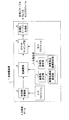
本発明の一実施形態に係る色修整装置の構成について、図1を用いて説明する。本実施形態の色修整装置1は、図1に示すように、色空間変換部2と、色指定部3と、色修整部4と、ガマットマッピング部5と、色補正テーブル生成部(色補正テーブル生成手段)6とを備えている。
[1. (Configuration of color correction device)
A configuration of a color correction apparatus according to an embodiment of the present invention will be described with reference to FIG. As shown in FIG. 1, the
色空間変換部2は、スキャナやデジタルカメラ等の画像入力装置の入力特性(入力プロファイル)に基づいて、たとえばRGBデータからなる入力画像データをデバイスに依存しない色表色系に変換する。
The color
そのような色表色系としては、たとえば、CIE(Commission International de l’Eclairage:国際照明委員会)により定められたL*a*b*表色系(L*:明度、a*・b*:色度)、L*u*v*表色系(L*:明度、u*・v*:色度)、IPT表色系(I:Intensity(強度、明るさの次元)、P:Protan(赤色−緑色の次元)、T:Tritan(黄色−青色次元))などを用いることができる。入力画像データをこのような表色系に変換する方法では、下記の入力プロファイルを用いる。 As such a color system, for example, the L * a * b * color system (L * : lightness, a * · b * ) defined by the CIE (Commission International de l'Eclairage) . : Chromaticity), L * u * v * color system (L * : lightness, u * · v * : chromaticity), IPT color system (I: Intensity (dimension of intensity, brightness)), P: Protan (Red-green dimension), T: Tritan (yellow-blue dimension)) and the like can be used. In the method of converting input image data into such a color system, the following input profile is used.
入力プロファイルとは、入力デバイス(スキャナ、デジカメなどの画像入力装置)の色再現領域特性を表したものであり、入力画像データをデバイスに依存しない表色系に変換するためのテーブルが含まれている。入力プロファイルは、たとえば下記の(1)〜(3)の手順を踏むことにより作成する。 An input profile represents the color reproduction area characteristics of an input device (an image input device such as a scanner or digital camera), and includes a table for converting input image data into a color system independent of the device. Yes. The input profile is created, for example, by following the procedures (1) to (3) below.
(1)カラーチャート原稿における各色のパッチを測色器で測色し、L*a*b*値を求める。これにより、入力画像データから、L*a*b*表色系のデータが求められる。 (1) Measure the color patches of the color chart document with a colorimeter to determine the L * a * b * value. As a result, L * a * b * color system data is obtained from the input image data.
(2)測色に用いたカラーチャート原稿をカラー画像入力装置から読み取り、カラーチャート原稿のRGB値を得る。 (2) The color chart document used for color measurement is read from the color image input device, and the RGB values of the color chart document are obtained.
(3)測色したL*a*b*値と、カラー画像入力装置から読み取ったRGB値とを対応付けるため、ニューラルネットワークやマスキング演算係数決定法により、L*a*b*値とRGB値との間の係数を求め、カラー画像入力装置の入力特性を定義する。 (3) In order to associate the L * a * b * values measured by color with the RGB values read from the color image input device, the L * a * b * values and the RGB values are determined by a neural network or a masking calculation coefficient determination method. The coefficient between is obtained, and the input characteristics of the color image input device are defined.
色指定部3は、修整色設定部7と、目標色設定部8と、修整色領域設定部(修整色領域設定手段)9と、修整周辺領域設定部(修整周辺領域設定手段)10とを備えている。
The color designation unit 3 includes a modified color setting unit 7, a target
修整色設定部7は、ユーザーあるいはサービスマンが、色修整したい色(修整前の色、修整色)を設定するためのものである。また、目標色設定部8は、色修整したい色を修整する際に、修整の目標となる色(目標色)をユーザー等が設定するためのものである。また、修整色領域設定部9は、修整したい色と同様の色修整が行われる色空間上の領域(修整色領域)を、ユーザー等が設定するためのものである。また、修整周辺領域設定部10は、色修整の影響を及ぼす色空間上の領域(修整周辺領域)を、ユーザー等が設定するためのものである。
The modified color setting unit 7 is for the user or service person to set a color (color before modification, modified color) that the user wants to modify. In addition, the target
色指定部3は、上記構成により、色修整部4が色修整のために用いるパラメーターとして、色修整したい色、目標色、修整したい色と同様の色修整を行う領域、および色修整の影響を及ぼす色空間上の領域を生成する。なお、色指定部3を構成する各ブロックは、タッチペン、タッチパネル、またはキーボード等のユーザー入力を受け付けるハードウェア資源により実現することができる。 With the above-described configuration, the color designating unit 3 uses the color modification unit 4 as parameters used for color modification, the color to be modified, the target color, the area where the color modification similar to the color to be modified is performed, and the influence of the color modification. Generate an area on the affected color space. Each block constituting the color specifying unit 3 can be realized by hardware resources that accept user input such as a touch pen, a touch panel, or a keyboard.
色修整部4は、色指定部3における各ブロックで生成されたパラメーターに基づいて、デバイスに依存しない表色系、たとえばL*a*b*表色系における所定領域に対して、色修整を行う。色修整の方法に関しては、後に詳細を記載する。 Based on the parameters generated in each block in the color designating unit 3, the color modification unit 4 performs color modification on a predetermined area in a color system that does not depend on a device, for example, L * a * b * color system. Do. Details of the color correction method will be described later.
ガマットマッピング部5は、入力デバイスの色再現領域を、出力デバイスの色再現特性(出力プロファイル)に基づいて、出力デバイスの色再現領域に整合させる処理(ガマットマッピング)を実行するためのものである。なお、ガマットマッピングの方法としては、たとえば、下記の(1)〜(4)に示す方法を用いることができる。
The
(1)absolute colorimetric法
absolute colorimetric法では、入力画像データにより示される色空間上の位置が、画像出力装置の色再現領域外にある場合、入力画像データの示す色空間上の位置と最も近い位置にある色再現領域の外縁部が、その入力画像データの示す色空間上の位置となるように、入力画像データを圧縮する。このabsolute colorimetric法では、目標色(入力された色)に最も近いCMY値を出力することができるため、正確な色再現を行うことが可能となる。
(1) Absolute colorimetric method
In the absolute colorimetric method, when the position on the color space indicated by the input image data is outside the color reproduction area of the image output device, the color reproduction area closest to the position on the color space indicated by the input image data is displayed. The input image data is compressed so that the outer edge is positioned on the color space indicated by the input image data. In the absolute colorimetric method, since the CMY value closest to the target color (input color) can be output, accurate color reproduction can be performed.
ただし、absolute colorimetric法では、色空間上の位置が色再現領域外となる入力画像データの全てが圧縮されてしまうため、色再現領域の外縁部付近の色で階調性が低下する場合がある。 However, in the absolute colorimetric method, all input image data whose position in the color space is outside the color reproduction area is compressed, so that gradation may be deteriorated with colors near the outer edge of the color reproduction area. .
(2)relative colorimetric法
上述のabsolute colorimetric法では、色再現の正確さは得られるものの、階調性の低下が生じるため、その階調性低下を抑制しようとするのがrelative colorimetric法である。すなわち、relative colorimetric法では、入力画像データにより示される色空間上の位置が色再現領域外となる場合、その入力画像データの示す位置が色再現領域の外縁部周辺の狭い領域に収まるように入力画像データを圧縮することで、階調性低下を抑制している。
(2) Relative colorimetric method In the above-described absolute colorimetric method, although the accuracy of color reproduction can be obtained, the gradation property is degraded. Therefore, the relative colorimetric method is intended to suppress the gradation property degradation. That is, in the relative colorimetric method, when the position on the color space indicated by the input image data is outside the color reproduction area, the input is indicated so that the position indicated by the input image data falls within a narrow area around the outer edge of the color reproduction area. By compressing the image data, a reduction in gradation is suppressed.
したがって、relative colorimetric法では、階調の飽和が発生しやすい色再現領域の外縁部付近の色についても、階調性を維持した色再現を行うことが可能となる。 Therefore, in the relative colorimetric method, it is possible to perform color reproduction while maintaining gradation characteristics for colors near the outer edge of a color reproduction area where gradation saturation is likely to occur.
(3)perceptual法
perceptual法は、色相を維持して彩度圧縮を行う方法である。perceptual法では、広い色域を持つ印画紙写真のような原稿でも、階調を飽和させることなく色再現を行うことができる。
(3) Perceptual method
The perceptual method is a method of performing saturation compression while maintaining the hue. In the perceptual method, even a document such as a photographic paper photograph having a wide color gamut can be reproduced without saturating the gradation.
(4)saturation法
saturation法は、できるだけ彩度が維持されるように入力画像データの圧縮を行う方法である。
(4) Saturation method
The saturation method is a method of compressing input image data so that saturation is maintained as much as possible.
なお、ガマットマッピングは、色再現領域全体に対して行ってもよいし、色修整した部分のみに行ってもよい。 Note that the gamut mapping may be performed on the entire color reproduction region, or may be performed only on the color-corrected portion.
ここで、出力プロファイルについて説明する。出力プロファイルは、電子写真方式やインクジェット方式を用いた画像出力装置(出力デバイス)の色再現領域特性を表したものである。出力プロファイルには、デバイスに依存しない表色系を出力画像データ(たとえば、CMYK色からなる画像データ)に変換するためのテーブルが含まれている。 Here, the output profile will be described. The output profile represents color reproduction region characteristics of an image output apparatus (output device) using an electrophotographic system or an inkjet system. The output profile includes a table for converting a device independent color system into output image data (for example, image data composed of CMYK colors).
また、出力プロファイルは、たとえば以下の(1),(2)の手順を踏むことにより作成することができる。 Further, the output profile can be created by, for example, following the procedures (1) and (2) below.
(1)カラー画像出力装置で出力可能な色座標を示すカラー画像データ(CMYK色の画像データ)を、たとえば原稿に出力し、その原稿における色を測色器で測定する。これによって、画像データに対応するL*a*b*表色系のデータが得られる。 (1) Color image data (CMYK color image data) indicating color coordinates that can be output by a color image output device is output to, for example, a document, and the color in the document is measured by a colorimeter. As a result, L * a * b * color system data corresponding to the image data is obtained.
(2)測色したL*a*b*値と、上記カラー画像データとを対応付けるべく、ニューラルネットワークやマスキング演算係数決定法によりL*a*b*値とCMYK値との間の係数を求めることによって、カラー画像出力装置の出力特性が定義される。 (2) A coefficient between the L * a * b * value and the CMYK value is obtained by a neural network or a masking calculation coefficient determination method in order to associate the colorimetric L * a * b * value with the color image data. Thus, the output characteristics of the color image output device are defined.
色補正テーブル生成部6は、色修整部4で実行された色修整処理の結果に基づき、入力画像データと出力画像データとが対応付けられたルックアップテーブル、もしくは、ICC(International Color Consortium)プロファイルを生成するものである。入力画像データは、たとえばRGB色からなるデータであり、出力画像データは、たとえばCMY色やCMYK色からなるデータである。また、出力装置がディスプレイならば、出力画像データとしては、たとえばRGB色からなる画像データを用いることができる。
The color correction
また、色補正テーブルは、特定の機器における色補正テーブルデータしか書き込まれていないものがある。一方、ICCプロファイルは、入出力機器固有の色特性を補正するカラーマネージメントシステム等の各社各様の規格を統一したものであり、モニターやプリンタなどの各機器の情報もタグとして書き込まれているものである。ICCプロファイルについても、広義の意味では、「色補正テーブル」の文言に含まれるものである。 Some color correction tables have only color correction table data written in a specific device. On the other hand, the ICC profile is a standardized standard for each company such as a color management system that corrects color characteristics unique to input / output devices, and information on each device such as a monitor or printer is also written as a tag. It is. The ICC profile is also included in the wording of “color correction table” in a broad sense.
〔2.色修整方法〕
本発明の一実施形態に係る色修整方法について以下に説明する。
[2. (Color correction method)
A color correction method according to an embodiment of the present invention will be described below.
先ず、ユーザーまたはサービスマンの指定により、以下のパラメーターが予め設定される。すなわち、ユーザー等の修整したい色が、図2に示すように、色空間上の点Aにより設定される。なお、点Aの設定は、修整色設定部7(図1)からのユーザー入力により行われる。 First, the following parameters are preset according to the designation of the user or service person. That is, the color that the user wants to modify is set by a point A on the color space, as shown in FIG. The point A is set by user input from the modified color setting unit 7 (FIG. 1).
また、点Aにより示される色を修整する際に目標となる色(目標色)が、色空間上の点A’により設定される。なお、点A’の設定は、目標色設定部8(図1)からのユーザー入力により行われる。 In addition, a target color (target color) for correcting the color indicated by the point A is set by the point A ′ in the color space. Note that the setting of the point A ′ is performed by user input from the target color setting unit 8 (FIG. 1).
さらに、点Aにより示される色と同様の色修整が行われる色空間上の領域が、色空間上の球体Sにより設定される。なお、球体Sの設定は、修整色領域設定部9(図1)からのユーザー入力により行われる。また、点Aにより示される色と同様の色修整が行われる領域は、必ずしも球体Sにより設定される必要はない。 Further, a region on the color space where the color correction similar to the color indicated by the point A is performed is set by the sphere S on the color space. The sphere S is set by user input from the modified color area setting unit 9 (FIG. 1). In addition, the region where the color correction similar to the color indicated by the point A is performed is not necessarily set by the sphere S.
ここで、球体Sは、点Aを中心とする半径rの球体である。なお、半径rは、色修整したい色を含めてどの範囲のものを最も色修整の対象にしたいかを設定するものである。たとえば単純に肌色といっても、色空間上である程度の大きさを有する領域に含まれる色は「肌色」と表現される。したがって、たとえば球体Sを設定することにより、ある程度の大きさを有する範囲を、色修整の対象とする必要がある。 Here, the sphere S is a sphere having a radius r centered on the point A. The radius r is used to set which range of colors including the color to be corrected is to be most targeted for color correction. For example, even if it is simply referred to as skin color, a color included in an area having a certain size in the color space is expressed as “skin color”. Therefore, for example, by setting the sphere S, it is necessary to set a range having a certain size as a target of color correction.
半径rは、たとえば以下のように設定することができる。すなわち、色修整したい画像を表示するタッチパネル式のモニターにおいて、ペンなどで色修整したい色の領域を指定することで肌色の一部を抽出し、抽出された肌色の色座標の平均値を、修整したい色の座標、すなわち点Aの座標として設定してもよい。さらに、その抽出された領域における色座標のばらつきを表す標準偏差、半径rとして設定してもよい。なお、点A、点A’、および半径rは、予め定められているものであっても構わない。たとえば、CIEL*a*b*空間において、色差の値が2や3の場合、視覚的に等色と感じられることから、2や3という値を半径rにしてもよい。
The radius r can be set as follows, for example. In other words, on a touch panel monitor that displays the image you want to correct the color, specify the area of the color you want to correct with a pen, etc., and extract a part of the skin color, and correct the average value of the color coordinates of the extracted skin color. You may set as the coordinate of the color to be desired, ie, the coordinate of the point A. Further, it may be set as a standard deviation and a radius r representing the color coordinate variation in the extracted area. Note that the point A, the point A ′, and the radius r may be determined in advance. For example, in the CIEL * a * b * space, when the value of the color difference is 2 or 3, since it is visually perceived as the same color, the
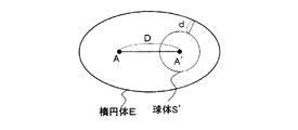
さらに、色修整の影響を及ぼす色空間上の領域を、たとえば楕円体Eにより設定する。なお、楕円体Eの設定は、修整周辺領域設定部10(図1)からのユーザー入力により行われる。また、色修整の影響を及ぼす色空間上の領域は、必ずしも楕円体により設定される必要はない。色修整の影響を及ぼす空間上の領域は、点Aにより示される色と同様の色修整が行われる領域を含むように設定されればよい。 Further, an area on the color space that is affected by the color modification is set by an ellipsoid E, for example. The ellipsoid E is set by user input from the modified peripheral area setting unit 10 (FIG. 1). Further, the area on the color space that is affected by the color modification is not necessarily set by an ellipsoid. The area on the space in which the color modification affects may be set so as to include the area where the color modification similar to the color indicated by the point A is performed.
以下の説明では、色修整により球体Sが移動する方向(詳細は後述する)に関する、楕円体Eの中心と楕円体Eの端部との距離をaとする。また、色修整により球体Sが移動する方向に垂直な方向に関する、楕円体Eの中心と楕円体Eの端部との距離をbとする。なお、a=bであれば、楕円体Eは球体になる。また、点Aと点A’が指定されれば、その領域に応じて自動的に球体Sと楕円体Eが設定されるようにしてもよい。 In the following description, the distance between the center of the ellipsoid E and the end of the ellipsoid E with respect to the direction in which the sphere S moves by color modification (details will be described later) is a. Also, let b be the distance between the center of the ellipsoid E and the end of the ellipsoid E in the direction perpendicular to the direction in which the sphere S moves due to color modification. If a = b, the ellipsoid E becomes a sphere. Further, if the point A and the point A ′ are designated, the sphere S and the ellipsoid E may be automatically set according to the area.
このように、色修整の影響を及ぼす領域を楕円体として設定することにより、その領域を幾何学的に数式化し、容易なアルゴリズムで記述することが可能となる。また、色修整により球体Sが移動されることで影響が及ぼされる領域を、感覚的に容易に把握することができる。 In this way, by setting the area affected by the color modification as an ellipsoid, it is possible to mathematically formulate the area and describe it with an easy algorithm. In addition, it is possible to easily grasp a region that is affected by the movement of the sphere S due to color modification.
なお、楕円体Eは、球体Sに含まれる色を修整することにより影響を受ける領域の許容範囲としても表現できる。 The ellipsoid E can also be expressed as an allowable range of an area affected by modifying the color included in the sphere S.
また、視覚的に色の階調性が損なわれないように、修整したい色の座標と目標色の座標との距離に応じて、a、bの値を決定する必要がある。このようにa、bの値を決定する方法について、図3を用いて説明する。 In addition, the values of a and b need to be determined according to the distance between the coordinates of the color to be modified and the coordinates of the target color so that the gradation of the color is not visually impaired. A method for determining the values of a and b will be described with reference to FIG.
すなわち、色修整後の目標色である点A’を中心とする球体S’の表面と楕円体Eの境界との間の最短距離dと、修整前の色である点Aと目標色である点A’との間の距離Dとの比率d/Dが、視覚的に色の階調性が保たれるある一定値以上になればよい。比率d/Dが大きければ、色修整による色の変化が距離Dに対し急峻にならないため、階調性が保たれるためである。なお、色の階調性が保たれる一定値に関しては、種々の画像サンプルを用いて適切な値を定めればよい。 That is, the shortest distance d between the surface of the sphere S ′ centered on the point A ′ that is the target color after color modification and the boundary of the ellipsoid E, the point A that is the color before modification, and the target color. The ratio d / D with respect to the distance D between the point A ′ and the distance D may be equal to or greater than a certain value that visually maintains the color gradation. This is because if the ratio d / D is large, the color change due to the color modification does not become steep with respect to the distance D, so that the gradation is maintained. In addition, what is necessary is just to determine an appropriate value using a various image sample regarding the fixed value with which the gradation property of a color is maintained.
また、点Aと点A’を楕円体Eの焦点にすることによって、自動的に球体Sと楕円体Eの大きさを決めるようにしてもよい。 Alternatively, the size of the sphere S and the ellipsoid E may be automatically determined by making the point A and the point A ′ the focal point of the ellipsoid E.
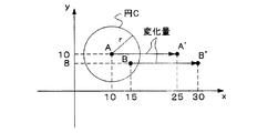
次に、本実施形態における色修整方法について、さらに具体的に説明する。先ず、球体S内の色は、点Aにより示される修整したい色と同様の色変換処理が行われる。この色変換処理は、3次元の色空間において行われるものであるが、説明の便宜上、2次元平面内の色変換処理に置き換えて図4を用いて説明する。 Next, the color correction method in the present embodiment will be described more specifically. First, the color in the sphere S is subjected to the same color conversion processing as the color to be corrected indicated by the point A. This color conversion process is performed in a three-dimensional color space, but will be described with reference to FIG. 4 instead of a color conversion process in a two-dimensional plane for convenience of explanation.
たとえば、点Aの座標がx=10、y=10で、点A’の座標がx=25、y=10であり、円Cの半径をr=6とする。なお、円Cは、球体Sを2次元平面に投影したものである。 For example, the coordinates of the point A are x = 10, y = 10, the coordinates of the point A ′ are x = 25, y = 10, and the radius of the circle C is r = 6. Note that the circle C is a projection of the sphere S on a two-dimensional plane.
この場合、修整したい色の変換量は、点A’から点Aを引いた差分として表現される。すなわち、この差分を変化量(Δx,Δy)として表現した場合、Δx=25−10=15、Δy=10−10=0である。 In this case, the conversion amount of the color to be corrected is expressed as a difference obtained by subtracting the point A from the point A ′. That is, when this difference is expressed as a change amount (Δx, Δy), Δx = 25−10 = 15 and Δy = 10−10 = 0.
そして、円Cの中に含まれる色は、すべて同等の変化量が適用される。ゆえに、円C内に含まれる点B(x=15、y=8)は、各xy成分に対して、変化量Δx、Δyを加算することで、点B’(x=30、y=8)に変換されることになる。このように、円Cに含まれる色については、同様の変化量を適用することによって色修整処理が行われる。この色修整処理が、3次元の色空間にも拡張適用される。 The same amount of change is applied to all the colors included in the circle C. Therefore, the point B (x = 15, y = 8) included in the circle C is obtained by adding the change amounts Δx, Δy to each xy component, thereby obtaining the point B ′ (x = 30, y = 8). ) Will be converted. Thus, for the colors included in the circle C, the color correction process is performed by applying the same change amount. This color modification process is extended and applied to a three-dimensional color space.
つまり、実際に修整の対象となる色は、色空間上においてある程度の大きさを有する範囲に含まれるので、その色の範囲全体を移動させることで、本実施形態の色修整が行なわれる。すなわち、球体Sに含まれる色が修整の対象となり、その球体S全体を移動させることで、球体Sに含まれる色を正確にかつ確実に修整することが可能になる。これにより、色再現の精度を向上させることができる。 In other words, the color that is actually subject to modification is included in a range having a certain size in the color space. Therefore, the color modification of this embodiment is performed by moving the entire color range. In other words, the color included in the sphere S is a target for correction, and the color included in the sphere S can be corrected accurately and reliably by moving the entire sphere S. Thereby, the accuracy of color reproduction can be improved.
また、本実施形態の色修整方法によれば、入出力装置における色再現性のばらつきがあったとしても、より正確に目標色に色修整が行われる。つまり、実際に入出力装置等の色特性は、製品ごとやその装置自体の経年変化によって一定でないことが多い。しかし、本実施形態の色修整方法では、修整前の色から所定の色差を有する範囲(球体S)に含まれる色に対して同一の修整を施すので、製品のばらつきや経年変化により色再現性に変化が生じたとしても、適格な色修整を行うことができる。 Further, according to the color correction method of the present embodiment, even if there is a variation in color reproducibility in the input / output device, the color correction is performed more accurately on the target color. In other words, the color characteristics of the input / output device or the like are often not constant due to aging of each product or the device itself. However, in the color correction method of the present embodiment, the same correction is applied to the color included in the range (sphere S) having a predetermined color difference from the color before correction, so that color reproducibility due to product variations and aging changes. Even if there is a change in color, appropriate color correction can be performed.
また、図5(a)および図5(b)に示すように点Aを中心とする球体Sを、点A’を中心とする球体に移動した際に、楕円体E内の色空間は、図5(b)に示すように、球体Sが移動した方向に関しては圧縮され、球体が移動した方向と反対方向に関しては伸張される。 When the sphere S centered on the point A is moved to the sphere centered on the point A ′ as shown in FIGS. 5A and 5B, the color space in the ellipsoid E is As shown in FIG. 5B, the direction in which the sphere S moves is compressed, and the direction opposite to the direction in which the sphere has moved is expanded.
また、球体Sに近いほど修整度合い(楕円体内の点移動量)は大きく、球体Sから離れれば離れるほど修整度合いは連続的に小さくなる。また、色修整により影響が及ぼされる領域の境界、すなわち楕円体の境界およびその領域外では色修整されない。 Further, the closer to the sphere S, the greater the degree of modification (the amount of point movement within the ellipsoid), and the smaller the distance from the sphere S, the smaller the degree of modification continuously. Further, the color correction is not performed outside the boundary of the area affected by the color correction, that is, the boundary of the ellipsoid.
このような色修整の前後において色空間が変化する状態について、説明の便宜上、球体Sおよび楕円体Eのそれぞれを2次元平面に投影して得られる円Cおよび楕円を用いて説明する。 For convenience of explanation, the state in which the color space changes before and after such color modification will be described using a circle C and an ellipse obtained by projecting each of the sphere S and the ellipsoid E onto a two-dimensional plane.
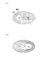
つまり、図6(a)に示すように、色修整の対象となる領域が円Cとして設定され、色修整の影響を及ぼす領域が楕円により設定されているとする。この円Cを、点Aにより示される色の目標色を示す点A’を中心とする円に移動させる場合、図6(b)に示すように、円Cより右側の色空間は圧縮され、円Cより左側の色空間は伸張される。さらに、楕円の境界上の色は色修整されないので、色修整の前後においてその座標が固定されたままである。 That is, as shown in FIG. 6A, it is assumed that an area to be subjected to color modification is set as a circle C, and an area that affects color modification is set by an ellipse. When the circle C is moved to a circle centered on the point A ′ indicating the target color of the color indicated by the point A, the color space on the right side of the circle C is compressed as shown in FIG. The color space on the left side of the circle C is expanded. Furthermore, since the color on the boundary of the ellipse is not color-corrected, its coordinates remain fixed before and after the color correction.
このような色修整による色空間の圧縮/伸張状態は、楕円内に格子座標を想定することにより容易に理解することができる。すなわち、図6(a)に示すように、色修整の前においては、楕円内に格子座標が規則正しく設定される。 The compression / decompression state of the color space due to such color modification can be easily understood by assuming grid coordinates in the ellipse. That is, as shown in FIG. 6A, before the color correction, lattice coordinates are regularly set in the ellipse.
そして、色修整後においては、図6(b)に示すように、円Cの右側の格子は圧縮され、円Cの左側の格子は伸張された状態となる。 After the color correction, as shown in FIG. 6B, the grid on the right side of the circle C is compressed and the grid on the left side of the circle C is in an expanded state.
このような色修整処理を行うにあたっては、座標変換関数を用いて、楕円内にあるすべての点(色)を再計算し、色修整を行う。その座標変換関数の一例を以下に説明する。 In performing such color correction processing, all points (colors) in the ellipse are recalculated using the coordinate conversion function, and color correction is performed. An example of the coordinate conversion function will be described below.
点Aと点A’の線上の点に対して座標変換関数を用いて新たな点xを導出する場合において、線分AA’と円Cの交点をx0とすると、xとx0との距離Lを求める関数f(x)は以下のようになる。 When a new point x is derived for the points on the line of points A and A ′ using the coordinate transformation function, if the intersection of the line segment AA ′ and the circle C is x 0 , x and x 0 A function f (x) for obtaining the distance L is as follows.
f(x)=L=|x−x0|
また、線分AA’の延長線と楕円との交点をx1とし、線分AA’の距離をDとすると、移動量(修整量)は、距離Lに応じた関数g(L)により導出された重み係数wを距離Dに乗算することにより求められる。
f (x) = L = | x−x 0 |
The derivation line AA 'of intersection of the extension line and the ellipse and x 1, the line segment AA' and the distance is D, the movement amount (modification amount), the distance L function corresponding to g (L) Is obtained by multiplying the distance D by the weighting factor w.
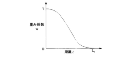
関数g(L)としては、たとえば図7に示すように、距離Lが0のときに重み係数wを1に設定する一方、距離L1(=x1−x0)のときに重み係数wを0に設定する関数であることが望ましい。さらに、関数g(L)は、距離Lが0からL1の間にある場合は、重み係数wが単調減少する関数であることが望ましい。 As the function g (L), for example, as shown in FIG. 7, the weighting factor w is set to 1 when the distance L is 0, while the weighting factor w is set when the distance L 1 (= x 1 −x 0 ). The function is preferably set to 0. Furthermore, the function g (L), when the distance L is between 0 and L 1 is preferably the weighting factor w is a monotonically decreasing function.
このように関数g(L)を設定すれば、点xが円Cに近い程重み係数wが大きくなるので、移動量(色修整量)は距離Dに近づく。また、点xと円Cとの間における距離がL1(楕円の境界)になると重み係数wは0になるため色修整されない。最終的に、新たな点x’は以下のように求められる。 When the function g (L) is set in this way, the weight coefficient w increases as the point x is closer to the circle C, so that the movement amount (color correction amount) approaches the distance D. Further, when the distance between the point x and the circle C is L 1 (ellipse boundary), the weighting coefficient w becomes 0, and the color is not corrected. Finally, a new point x ′ is obtained as follows.
x’=x+D・W
=x+D・g(L)
=x+D・g(f(x))
そして、この2次元平面における色修整処理は、3次元空間に拡張して実行される。3次元に拡張する方法の一例としては、以下の方法が考えられる。
x ′ = x + D · W
= X + D · g (L)
= X + D · g (f (x))
Then, the color modification processing in the two-dimensional plane is executed by extending to a three-dimensional space. The following method can be considered as an example of the method of extending in three dimensions.
まず、図8に示すように、色修整の影響を及ぼす領域である楕円体Eを色空間から抽出し、その楕円体Eの中心が原点になるように、平行移動および2度の回転処理を楕円体に対して行う。そして、修整したい色(点A)から目標点(点A’)に向かう向きが常に同じになるようにする。 First, as shown in FIG. 8, an ellipsoid E, which is an area in which color modification is affected, is extracted from the color space, and parallel movement and two-degree rotation processing are performed so that the center of the ellipsoid E is the origin. Do this for an ellipsoid. The direction from the color to be corrected (point A) to the target point (point A ′) is always the same.
その結果、線分AA’を常にX軸上に位置するよう設定できるため、楕円体EをX−Y平面と平行な複数の平面で切断し、その各平面に対して、前述の2次元平面内での色修整方法を用いて、色修整を行う。これにより、楕円体E内の全点についての色修整が終了したら、前述の平行移動および2度の回転処理の逆処理を楕円体Eに対して行い、楕円体Eを元の位置に戻す。なお、2度の回転処理は1度の回転処理で済ませてもよく、平行移動と回転処理の順番は任意に選択可能である。 As a result, the line segment AA ′ can be set so as to always be positioned on the X axis, so that the ellipsoid E is cut along a plurality of planes parallel to the XY plane, and the above-described two-dimensional plane is obtained for each plane. Color correction is performed using the internal color correction method. As a result, when the color correction is completed for all points in the ellipsoid E, the parallel processing and the reverse processing of the two-degree rotation processing described above are performed on the ellipsoid E, and the ellipsoid E is returned to the original position. Note that the two rotation processing may be completed by one rotation processing, and the order of the parallel movement and the rotation processing can be arbitrarily selected.
以上の方法により、2次元の色修整方法を容易に3次元に拡張することが可能となり、アルゴリズムの簡易化が図れ、処理の高速化が可能となる。 By the above method, the two-dimensional color correction method can be easily extended to three dimensions, the algorithm can be simplified, and the processing speed can be increased.
さらに、上述のような色修整処理を行うことにより、修整後の色が色空間内で連続的に変化するので、トーンギャップや色とびが生じないことになる。また、球体Sおよび楕円体Eを適切に設定すれば、画像において色修整したい部分のみ修整できるので、必要最小限に色が修整される。 Further, by performing the color correction process as described above, the corrected color continuously changes in the color space, so that no tone gap or color jump occurs. Further, if the sphere S and the ellipsoid E are set appropriately, only the portion of the image where the color correction is desired can be corrected, so that the color is corrected to the minimum necessary.
また、ユーザー(またはサービスマン)の設定により、目標色や色修整の影響が及ぼされる領域が出力デバイスのガマット(色再現域)外である場合、色修整後のガマットマッピングのアルゴリズムに基づいて、出力デバイスで色再現可能な領域に変換される。これを行うことで、ユーザーが目標色をガマット外に設定しても、できるだけ目標色に近い色の再現ができるようになる。 Also, if the target color or the area affected by color modification is outside the output device's gamut (color reproduction area) due to user (or serviceman) settings, based on the gamut mapping algorithm after color modification, Converted to an area that can be reproduced by the output device. By doing this, even if the user sets the target color outside the gamut, it is possible to reproduce a color as close to the target color as possible.
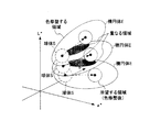
また、色修整の対象とする領域、および色修整の影響を及ぼす領域については、図9に示すように、複数設定することも可能である。このように複数の領域を設定することには、以下の意義がある。 In addition, as shown in FIG. 9, it is possible to set a plurality of areas that are subject to color modification and areas that are affected by color modification. Setting a plurality of areas in this way has the following significance.
すなわち、自然画像において、肌色、空の色、および芝の緑色などは、ある色相にあるものの広範囲かつ不規則に分布している。したがって、色修整の影響を及ぼす領域を大きく設定しすぎると、色修整の必要のないところまで色修整の影響を及ぼしてしまう場合がある。その反面、色修整の影響を及ぼす領域を1箇所設定するだけでは、十分な色修整が行えない場合がある。 That is, in a natural image, skin color, sky color, and green color of turf are distributed in a wide range and irregularly in a certain hue. Therefore, if the area where the color modification is influenced is set too large, the color modification may be affected to the point where the color modification is not necessary. On the other hand, there may be a case where sufficient color correction cannot be performed by setting only one area that affects color correction.
そこで、色修整の対象とする領域、および色修整の影響を及ぼす領域のそれぞれを複数設定し実行することで、上記の場合にでも色修整が可能になる。 Therefore, color correction can be performed even in the above case by setting and executing a plurality of areas to be subjected to color correction and areas that are affected by color correction.
なお、色修整を行う領域のそれぞれに対しては、上述した本実施形態の色修整方法に基づいて色修整される。また、複数の楕円体Eが重なる領域に関しては、それぞれの領域における色修整量の平均値、中間値、最多値などを用いて、色修整を行う。 It should be noted that the color correction is performed on each of the areas where the color correction is performed based on the color correction method of the present embodiment described above. In addition, for areas where a plurality of ellipsoids E overlap, color correction is performed using the average value, intermediate value, maximum value, etc. of the color correction amounts in the respective areas.
たとえば、複数の領域A,B,Cにおいて、色修整の対象となる点aが重なっている場合、それぞれの領域における色修整量が10、5、2であれば、その平均値((10+5+2)/3=5.7)が点aの修整量とされる。 For example, in a plurality of areas A, B, and C, when the points a targeted for color correction overlap, if the color correction amount in each area is 10, 5, or 2, the average value ((10 + 5 + 2) /3=5.7) is the amount of correction at point a.
また、本実施形態の色修整方法においては、グレーバランスを保ちながら、所望の色修整を行うことも可能である。そのためには、色空間のL*軸からある一定の距離を有する領域については色修整を行わず、それ以外の領域はL*軸からの距離(彩度)に応じて色修整の度合いを変える必要がある。 In the color modification method of the present embodiment, desired color modification can be performed while maintaining gray balance. For this purpose, color correction is not performed for an area having a certain distance from the L * axis of the color space, and the degree of color correction is changed according to the distance (saturation) from the L * axis for other areas. There is a need.
色修整を行わない領域(グレー成分領域)は、たとえば図10(a)に示すように、L*軸を中心とする半径r2の円柱領域として設定できる。なお、r2の値は、種々の画像サンプルに基づいて適切な値を求めればよい。また、色修整を行わない領域においては、たとえば無彩色(グレースケール)を再現することができる。 An area where no color correction is performed (gray component area) can be set as a cylindrical area having a radius r2 centered on the L * axis, as shown in FIG. 10A, for example. In addition, what is necessary is just to obtain | require an appropriate value for the value of r2 based on various image samples. Further, for example, an achromatic color (gray scale) can be reproduced in a region where color correction is not performed.
色修整を行わない領域を図10(a)に示すように設定した場合、ある色修整する色の彩度がr2より高ければ高いほど、色修整量の大きさが大きく設定される。そのように色修整量の大きさを設定するためには、たとえば図10(b)に示すような修整量重み係数を導出するための関数を用いればよい。 When the area where color correction is not performed is set as shown in FIG. 10A, the color correction amount is set to be larger as the saturation of a color to be corrected is higher than r2. In order to set the color correction amount in such a manner, for example, a function for deriving a correction amount weight coefficient as shown in FIG. 10B may be used.
この修整量重み係数を導出するための関数は、横軸に彩度が設定され、彩度に対応する修整量の重み係数が縦軸に設定されている関数である。具体的に説明すると、この関数は、図10(b)に示すように、彩度が0からr2の範囲にあれば、重み係数として0を出力し、彩度がr2より大きければ、重み係数が単調増加する関数である。さらに、図10(b)に示すように、修整量の重み係数を導出するための関数では、彩度が所定値以上になると、重み係数が定常的に1になるように設定されている。この関数により導出された修整量重み係数に色修整の修整量を乗算することで、最終的な修整量を求め、それを色修整前のL*a*b*値に加算することで色修整を行う。 The function for deriving the modification amount weighting coefficient is a function in which saturation is set on the horizontal axis and the weighting coefficient of the modification amount corresponding to the saturation is set on the vertical axis. Specifically, as shown in FIG. 10 (b), this function outputs 0 as a weighting factor if the saturation is in the range of 0 to r2, and if the saturation is greater than r2, this function outputs the weighting factor. Is a monotonically increasing function. Further, as shown in FIG. 10B, in the function for deriving the weighting coefficient of the modification amount, the weighting coefficient is set to be constantly 1 when the saturation is equal to or higher than a predetermined value. The final correction amount is obtained by multiplying the correction amount weight coefficient derived by this function by the correction amount of the color correction, and is added to the L * a * b * value before the color correction. I do.
このように関数を設定することにより、グレー軸(L*軸)付近(0≦x≦r2の範囲)は、重み係数が0であるため、色修整は行われないため、グレーバランスが保たれる。そして、入力値とr2との差が大きくなることにより、重み係数を単調増加させることで、本来色修整したい量を反映していくことができ、色修整の連続性を保つことが可能となる。そして、重み係数が定常的に1となる状態では、色修整したい量が完全に反映される。よって、上記のような関数を用いることにより、グレーバランスと色修整の連続性を保ちながら、色修整を行うことが可能となる。 By setting the function in this way, the gray balance is maintained in the vicinity of the gray axis (L * axis) (the range of 0 ≦ x ≦ r2) because the weight coefficient is 0 and color correction is not performed. It is. Since the difference between the input value and r2 increases, the weight coefficient is monotonously increased, so that the amount of color correction originally intended can be reflected, and the continuity of color correction can be maintained. . In the state where the weighting coefficient is constantly 1, the amount to be corrected is completely reflected. Therefore, by using the function as described above, it is possible to perform color correction while maintaining continuity of gray balance and color correction.
たとえば、入力されたL*a*b*値の彩度がr2以下である場合、図10(b)の関数から修整量の重み係数が0として導出されるので、重み係数を乗算する前の色修整量がどのような値であるかに係わらず、最終的な修整量は0になり、色修整はされない。 For example, when the saturation of the input L * a * b * value is equal to or less than r2, the weighting coefficient of the modification amount is derived as 0 from the function of FIG. Regardless of the value of the color correction amount, the final correction amount is 0, and the color correction is not performed.
すなわち、彩度がr2以下では、L*a*b*値は変更されないため、グレーバランスは保存されることになる。また、入力L*a*b*値の彩度がr2より大きい場合、たとえば、図10(b)において彩度がC2の場合、対応する修整量の重み付けは0.5であるため、重み係数を乗算する前に算出された色修整量が2であれば、最終的な色修整量は2×0.5で1になる。したがって、入力L*a*b*値に1を加算した値が、最終的に色修整された値となる。このようにして修整量に重み付けを行うことにより、グレーバランスを保ちながら、所望の色修整を行うことができる。 That is, when the saturation is r2 or less, the L * a * b * value is not changed, and the gray balance is preserved. When the saturation of the input L * a * b * value is greater than r2, for example, when the saturation is C2 in FIG. 10B, the weight of the corresponding modification amount is 0.5. If the color correction amount calculated before multiplying by 2 is 2, the final color correction amount is 1 at 2 × 0.5. Therefore, a value obtained by adding 1 to the input L * a * b * value is finally a color-corrected value. By weighting the correction amount in this way, desired color correction can be performed while maintaining the gray balance.
〔3.色修整方法の処理フロー〕
次に、本実施形態の色修整方法を実現するソフトウェアプログラムにより、リアルタイムで入力デバイスからの入力画像を出力デバイスの出力画像に変換する場合における処理フローを、図11のフローチャートに基づき説明する。
[3. (Color correction method processing flow)
Next, a processing flow in the case of converting an input image from the input device into an output image of the output device in real time by a software program that implements the color correction method of the present embodiment will be described based on the flowchart of FIG.
なお、この処理フローは、コンピュータシステムで行ってもよいし、出力デバイスの操作パネルからのユーザー入力に応じて行われてもかまわない。ここで、出力デバイスの操作パネルは、液晶ディスプレイ等の表示部、画像の表示モード等を設定する設定キー、およびテンキーなどにより構成されるものである。また、本実施形態の色修整方法を実現するソフトウェアプログラムは、コンピュータ読み取り可能な記録媒体に格納されて提供されてもよい。 This processing flow may be performed by a computer system or may be performed in response to a user input from the operation panel of the output device. Here, the operation panel of the output device includes a display unit such as a liquid crystal display, a setting key for setting an image display mode, and a numeric keypad. The software program for realizing the color correction method of the present embodiment may be provided by being stored in a computer-readable recording medium.
先ず、本実施形態の色修整方法の処理フローでは、入力デバイスにより、入力画像データが読み込まれる(ステップ1、以下「ステップ」は単に「S」と記載する)。S1における入力画像データの読み込みは、たとえば入力原稿をRGB色の画像データとして読み込むことにより行われる。
First, in the processing flow of the color correction method of the present embodiment, input image data is read by the input device (
その後、入力画像データの表色系から、デバイスに依存しない表色系(たとえば、L*a*b*表色系)に変換するためのテーブルが含まれた入力プロファイルが、色空間変換部2(図1参照)により読み込まれる(S2)。
Thereafter, an input profile including a table for converting from the color system of the input image data to a device-independent color system (for example, L * a * b * color system) is converted into the color
さらに、S2で読み込まれた入力プロファイルを元に、色空間変換部2により、入力画像データがデバイスに依存しない表色系に変換される(S3)。デバイスに依存しない表色系としては、CIEL*a*b*表色系、L*u*v*表色系、IPT表色系などを用いることができる。
Further, based on the input profile read in S2, the color
その後、色修整をしたい色が指定されているか否かが判断される(S4)。S4における判断は、たとえば、液晶ディスプレイ等のタッチパネル式のモニターに表示された画像について、色修整をしたい色をユーザーがタッチペンなど用いて指定しているか否かが、コンピュータの制御部により判断されることによって実現される。 Thereafter, it is determined whether or not a color to be corrected is designated (S4). The determination in S4 is performed by the control unit of the computer, for example, whether or not the user specifies the color to be corrected for the image displayed on a touch panel monitor such as a liquid crystal display using a touch pen or the like. Is realized.
S4において色指定がされていると判断された場合、後述するS5において目標色等が設定された後、S6において色修整が行われる。一方、S4において色指定がされていないと判断された場合、後述するS7の出力プロファイル読み込み処理、S8のガマットマッピング処理、S9の色空間変換処理が実行される。 If it is determined in S4 that a color has been designated, a target color or the like is set in S5 described later, and then color correction is performed in S6. On the other hand, if it is determined in S4 that no color is designated, an output profile reading process in S7, a gamut mapping process in S8, and a color space conversion process in S9, which will be described later, are executed.
S5の処理について説明する。S5においては、色修整に用いる各種パラメーター、すなわち、ユーザーが修整したい色(修整色)、修整色に対する目標色、修整色と同様の色修整が行われる色空間上の領域、および色修整の影響を及ぼす色空間上の領域等のパラメーターの設定が、修整色設定部7、目標色設定部8、修整色領域設定部9、および修整周辺領域設定部10のそれぞれを介したユーザー入力により行われる。
The process of S5 will be described. In S5, various parameters used for color correction, that is, the color that the user wants to correct (corrected color), the target color for the corrected color, the area on the color space where the same color correction as the corrected color is performed, and the influence of the color correction The parameters such as the area on the color space that affects the color are set by user input via the modified color setting unit 7, the target
S5における設定を行う方法としては、以下の(a)〜(d)に示す方法があり、これらの方法のうちいずれか1つの方法、または、複数の方法を組み合わせて、S5の設定を行うことができる。 As a method for setting in S5, there are methods shown in the following (a) to (d), and any one of these methods or a combination of a plurality of methods is set in S5. Can do.
(a)デバイスに依存しない表色系での数値(たとえば、L*・a*・b*値)を、色修整に用いるパラメーターとして、キーボード、タッチパネル等の入力デバイスから入力する。 (A) A numerical value in a color system that does not depend on a device (for example, L * · a * · b * value) is input from an input device such as a keyboard or a touch panel as a parameter used for color correction.
(b)入力画像をタッチパネル式のモニターに表示し、その画像の一部を色修整に用いるパラメーターとしてタッチペンなどで指定することで入力する。 (B) An input image is displayed on a touch panel monitor, and a part of the image is input by designating with a touch pen or the like as a parameter used for color correction.
(c)デバイスに依存しない表色系の空間をタッチパネル式のモニターに表示して、タッチペンなどで上記パラメーターを指定、もしくは、L*・a*・b*値をモニターに表示されたスライドバーで移動させる、または直接数値をキーボードから入力することにより、パラメーターを設定する。 (C) Display the device-independent color space on the touch panel monitor and specify the above parameters with a touch pen, etc., or use the slide bar that displays the L * / a * / b * values on the monitor. Set parameters by moving or entering numbers directly from the keyboard.
(d)モニターに表示された明度、彩度、色相のパラメータバーをスライドさせる、または、数値を入力することにより、パラメーターを設定する。 (D) Set the parameters by sliding the brightness, saturation, and hue parameter bars displayed on the monitor, or by entering numerical values.
なお、彩度C*、色相hは下記の式で表される。 Note that the saturation C * and the hue h are expressed by the following equations.
C*=√(a*2+b*2) h=tan-1(b*/a*)
(a)〜(d)の方法のいずれを用いた場合にも、修整色として設定した色がモニターのウィンドウに表示され、ユーザーがそれを確認し、修整色として決定することにより、修整色が入力される。もしウィンドウに表示された色が修整したい色でないならば、修整色を再設定することが可能である。また、色修整したくない場合はキャンセルも可能である。
C * = √ (a * 2 + b * 2 ) h = tan −1 (b * / a * )
When any of the methods (a) to (d) is used, the color set as the modified color is displayed on the monitor window, and the user confirms it and determines it as the modified color. Entered. If the color displayed in the window is not the color you want to modify, you can reset the modified color. If you do not want to correct the color, you can cancel it.
S5の後、色修整部4(図1参照)により、色修整処理が実行される(S6)。S6の色修整処理では、S5にて設定された各種パラメーターに基づき、デバイスに依存しない表色系において該当する領域に対して、色修整部4(図1参照)により色修整が行われる。S6における色修整処理が終了したら、再度S4の処理に戻る。 After S5, color correction processing is executed by the color correction unit 4 (see FIG. 1) (S6). In the color correction process of S6, the color correction unit 4 (see FIG. 1) performs color correction on the corresponding area in the color system that does not depend on the device, based on the various parameters set in S5. When the color correction process in S6 is completed, the process returns to S4 again.
また、S4において色指定がされていないと判断された場合、出力プロファイルの読み込み処理が、ガマットマッピング部5(図1参照)により行われる(S7)。なお、出力プロファイルとは、上述したとおり、デバイスに依存しない表色系を出力画像データに変換するためのテーブルが含まれたものである。 If it is determined in S4 that no color is designated, the output profile reading process is performed by the gamut mapping unit 5 (see FIG. 1) (S7). As described above, the output profile includes a table for converting a device-independent color system to output image data.
S7における出力プロファイルの読み込み処理の後、ガマットマッピング処理が、ガマットマッピング部5(図1参照)により実行される(S8)。ガマットマッピング処理は、上述したように、デバイスに依存しない表色系、たとえば、L*a*b*表色系において、入力画像データが出力デバイスで再現できない領域にある場合に、出力プロファイルに基づいて入力画像データを出力デバイスの再現できる領域に圧縮する処理である。なお、ガマットマッピングには、上記したabsolute colorimetric法,relative colorimetric法,perceptual法,saturation法等を用いることができる。また、このガマットマッピングは、色再現領域全体に対して行ってもよいし、色修整した部分のみに行っても構わない。 After the output profile reading process in S7, the gamut mapping process is executed by the gamut mapping unit 5 (see FIG. 1) (S8). As described above, the gamut mapping process is based on an output profile when input image data is in a region that cannot be reproduced by an output device in a device-independent color system, such as an L * a * b * color system. This is a process for compressing the input image data into an area that can be reproduced by the output device. For the gamut mapping, the above-described absolute colorimetric method, relative colorimetric method, perceptual method, saturation method, and the like can be used. Further, this gamut mapping may be performed on the entire color reproduction region, or may be performed only on the color-corrected portion.
S8の後、色空間変換処理が、図示しない制御部により実行される(S9)。S9の色変換処理では、S8で読み込まれた出力プロファイルを元に、デバイスに依存しない表色系を出力画像データ(RGB、CMY、CMYK)に変換する。なお、出力画像データがCMY表色系からなる場合は、墨生成が行われ、そのデータがCMYK表色系のデータに変換される。 After S8, a color space conversion process is executed by a control unit (not shown) (S9). In the color conversion process in S9, the device-independent color system is converted into output image data (RGB, CMY, CMYK) based on the output profile read in S8. When the output image data is in the CMY color system, black generation is performed and the data is converted into data in the CMYK color system.
〔4.色修整の具体例〕
次に、色修整を適用する分野の具体例について説明する。
[4. (Specific examples of color correction)
Next, a specific example of the field to which color correction is applied will be described.
(1)印刷業界における特色インキによる特定色の色再現
特色インキによって印刷業界で再現される色は、業者により異なる。特色インキの代表的なものには、大日本インキ化学工業のDIC(ディック、登録商標)、東洋インキ製造のTOYO(トーヨー、登録商標)、パントーン社のPANTONE(パントーン、登録商標)などがある。また、印刷業界では色見本帳、カラーガイド、カラーチップなどが発行されており、カラー番号において管理されている。ユーザーは、特色インキによる特定色と同じ色再現を得たい場合があるため、忠実な色再現における色修整が必要になる。
(1) Color reproduction of a specific color using a special color ink in the printing industry The color reproduced in the printing industry using a special color ink varies depending on the supplier. Representative spot color inks include DIC (Dick, registered trademark) of Dainippon Ink and Chemicals, TOYO (Toyo, registered trademark) of Toyo Ink, and PANTONE (pantone, registered trademark) of Pantone. In the printing industry, color sample books, color guides, color chips, and the like are issued and managed by color numbers. Since the user may want to obtain the same color reproduction as the specific color using the special color ink, it is necessary to perform color correction in faithful color reproduction.
この場合、以下の(a)〜(e)の手順を踏むことにより、忠実な色再現を行うことができる。 In this case, faithful color reproduction can be performed by following the steps (a) to (e) below.
(a)特色インキによる特定色のカラーチップをスキャナで読み込み、スキャナで読み込まれた画像を出力デバイスにて出力する。なお、このときの色補正テーブルは修整前のものが用いられている。また、出力デバイスによる画像出力の態様としては、印刷による画像出力、画像表示による出力等を挙げることができる。 (A) A color chip of a specific color using special color ink is read by a scanner, and an image read by the scanner is output by an output device. Note that the color correction table at this time is the one before modification. Examples of image output by the output device include image output by printing, output by image display, and the like.
(b)上記出力デバイスの出力結果と、特色インキによる特定色のカラーチップとを測色器で測色し、特色インキによる特定色のカラーチップの測色値を目標色、出力デバイスの出力結果から得られた測色値を修整前の色とする。 (B) The output result of the output device and the color chip of the specific color with the special color ink are measured with a colorimeter, the color measurement value of the specific color chip with the special color ink is the target color, and the output result of the output device The colorimetric value obtained from is used as the color before correction.
または、予めカラーチップの測色データをデータベースに格納しておき、印刷会社とカラー番号とを指定することにより特定色を指定し、測色データをデータベースから読み出すようにしてもよい。 Alternatively, color chip color measurement data may be stored in advance in a database, a specific color may be specified by specifying a printing company and a color number, and the color measurement data may be read from the database.
(c)特色インキによる特定色のための色修整を行う際、色空間において色修整が行われる領域以外の領域において、視覚的に色の階調性が損なわれないように、修整前の色と目標色との間における修整量に応じて、楕円体E(図5等参照)の大きさを決定する。また、球体S(図5等参照)の半径は、たとえば視覚的に色の違い生じる色差である約2の大きさに設定する。 (C) When performing color modification for a specific color with special color ink, the color before modification so that the color gradation is not visually impaired in the area other than the area where color modification is performed in the color space. The size of the ellipsoid E (see FIG. 5 etc.) is determined according to the amount of correction between the target color and the target color. Further, the radius of the sphere S (see FIG. 5 and the like) is set to a size of about 2, which is a color difference in which a color difference visually occurs, for example.
そして、修整色、目標色、楕円体E、球体S等の色修整に用いる各種パラメーターを色指定部3(図1参照)に入力する。楕円体Eの大きさを決定する方法としては、図3に示すように、たとえば、色修整後の目標色を中心とする球体S’の表面と、楕円体の境界間の最短距離(d)と修整前の色と目標色の移動距離(D)との比率(d/D)が視覚的に色の階調性が保つある一定値以上になるようにa、bの値を決める。 Then, various parameters used for the color modification such as the modified color, the target color, the ellipsoid E, and the sphere S are input to the color designation unit 3 (see FIG. 1). As a method of determining the size of the ellipsoid E, as shown in FIG. 3, for example, the shortest distance (d) between the surface of the sphere S ′ centered on the target color after color correction and the boundary of the ellipsoid The values of a and b are determined so that the ratio (d / D) between the color before correction and the movement distance (D) of the target color is not less than a certain value that visually maintains the gradation of the color.
比率(d/D)が大きければ、色の変化が移動距離に対し急峻にならないため、階調性が保たれるためである。 This is because, if the ratio (d / D) is large, the color change does not become steep with respect to the movement distance, so that gradation is maintained.
(d)色修整部4において、色修整の対象となる色のみ色修整が行われ、色補正テーブル生成部6により修整された色補正テーブルが出力される。
(D) The color modification unit 4 performs color modification only on the color modification target, and outputs the color correction table modified by the color correction
(e)ROM等の記憶媒体に記憶された色補正テーブルを、修整後の色補正テーブルに書き換える。 (E) The color correction table stored in a storage medium such as a ROM is rewritten to the corrected color correction table.
(2)自然画像の好みの色再現における色修整の場合
自然画像に関しては、経験から生じるユーザーに好みの色があり、これを記憶色という。この場合は、ユーザーが所望する色を目標色として設定する。この場合の色修整は、以下の(a)〜(d)の手順を踏むことにより行われる。
(2) In the case of color correction in the preferred color reproduction of a natural image With respect to a natural image, there is a user's favorite color resulting from experience, and this is called a memory color. In this case, the color desired by the user is set as the target color. In this case, the color correction is performed by following the steps (a) to (d) below.
(a)入力画像(入力デバイスによる取り込み画像)を色空間変換部2(図1参照)において、デバイスに依存しない色空間(たとえばL*a*b*表色系)に変換する。 (A) An input image (an image captured by an input device) is converted into a device-independent color space (for example, L * a * b * color system) in the color space conversion unit 2 (see FIG. 1).
(b)色指定部3において、入力画像から好みの色再現したい領域を指定し、デバイスに依存しない色空間における修整前の色を抽出する。修整前の色の抽出は、指定した領域における明度や色度の平均値、中間値、最多値などを算出することにより実現できる。 (B) The color designation unit 3 designates a desired color reproduction area from the input image, and extracts a color before modification in a device-independent color space. Extraction of the color before modification can be realized by calculating the average value, intermediate value, maximum value, etc. of the brightness and chromaticity in the designated area.
そして、ユーザー好みの色再現したい色を目標色として設定する。たとえば、ユーザーの主観評価により好みの肌色として数値化されている色を目標色に設定する。色修整の範囲に関しては、視覚的に色の階調性が損なわれないように、修整前の色と目標色との間における移動量に応じて、楕円体Eの大きさを決定すればよい。楕円体の大きさを決定する方法としては、上記と同様の方法を用いれば良い。 Then, the color desired to be reproduced by the user is set as the target color. For example, a color that is digitized as a favorite skin color by the user's subjective evaluation is set as the target color. Regarding the range of color correction, the size of the ellipsoid E may be determined according to the amount of movement between the color before correction and the target color so that the gradation of the color is not visually impaired. . As a method for determining the size of the ellipsoid, a method similar to the above may be used.
また、球体Sの大きさは、色修整する色が色空間においてある程度の広がりを有している。したがって、たとえば、色修整したい画像を表示するタッチパネル式のモニターにおいて、タッチペンなどで色修整したい色の領域を指定し、その指定された領域における明度や色度の標準偏差を、球体Sの半径とすればよい。そして、このように決定された色修整に用いる各種パラメーターを、色修整部4に入力する。 Further, the size of the sphere S is such that the color to be corrected has a certain extent in the color space. Therefore, for example, in a touch panel monitor that displays an image to be color-corrected, a color area to be color-corrected is specified with a touch pen or the like, and the standard deviation of brightness and chromaticity in the specified area is set as the radius of the sphere S. do it. Then, various parameters used for the color correction determined as described above are input to the color correction unit 4.
(c)色修整部4において、色修整の対象となる色のみ色修整が行われ、色補正テーブル生成部6により修整された色補正テーブルが出力される。
(C) The color modification unit 4 performs color modification only on the color to be corrected, and the color correction table modified by the color correction
(d)ROM等の記憶媒体に記憶された色補正テーブルを、修整後の色補正テーブルに書き換える。 (D) The color correction table stored in the storage medium such as the ROM is rewritten to the corrected color correction table.
色補正テーブルとしては、たとえば、全ての入力画像データの組合せに対する出力画像データ(色補正データまたは色変換データ)を予め計算して格納しておく直接変換法を用いて作成されたものを用いることができる。または、選択された一部の入力画像データの組合せに対する予め計算されたテーブル値を色補正テーブルに格納し、色補正テーブルにテーブル値が格納されている入力画像データの近傍の入力画像データについては、色補正テーブルに格納されているテーブル値を用いて補間演算により出力画像データを算出する構成であってもよい。 As the color correction table, for example, a table created using a direct conversion method in which output image data (color correction data or color conversion data) for all combinations of input image data is calculated and stored in advance is used. Can do. Alternatively, pre-calculated table values for some selected combinations of input image data are stored in the color correction table, and input image data in the vicinity of the input image data in which the table values are stored in the color correction table. The output image data may be calculated by interpolation using the table values stored in the color correction table.
また、色補正方法の形態としては、RGB表色系の画像データをR’G’B’表色系の画像データに変換する形態(ディスプレイの場合)、RGB表色系の画像データをCMYやCMYK表色系の画像データに変換する形態を挙げることができる。なお、色補正テーブルは、デジタル複写機やプリンタに好適に用いられるものである。 Further, as a form of the color correction method, an RGB color system image data is converted into R′G′B ′ color system image data (in the case of a display), and RGB color system image data is converted to CMY or An example of conversion to CMYK color system image data can be given. The color correction table is preferably used for a digital copying machine or a printer.
〔5.画像形成装置への適用例〕
次に、本実施形態の色修整装置1を適用可能な画像形成装置の一例であるデジタルカラー複写機の構成について、図12を用いて説明する。
[5. Example of application to image forming apparatus]
Next, the configuration of a digital color copying machine that is an example of an image forming apparatus to which the
図12に示すように、デジタルカラー複写機(画像形成装置)11は、カラー画像入力装置12と、カラー画像処理装置13と、カラー画像出力装置14と、操作パネル15とを備えている。
As shown in FIG. 12, the digital color copying machine (image forming apparatus) 11 includes a color
カラー画像入力装置12は、たとえばCCD(Charge Coupled Device )を備えたスキャナ部より構成され、原稿からの反射光像を、RGB(R:赤・G:緑・B:青)のアナログ信号としてCCDにて読み取って、カラー画像処理装置に入力するものである。
The color
カラー画像処理装置13は、A/D変換部16、シェーディング補正部17、入力階調補正部18、領域分離処理部19、色補正部20、黒生成下色除去部21、空間フィルタ処理部22、出力階調補正部23、および階調再現処理部24とから構成されている。これらのカラー画像入力装置12を構成する各ブロックの機能については後述する。
The color image processing device 13 includes an A /
カラー画像出力装置14は、画像データを記録媒体(たとえば紙等)上に出力するもので、たとえば、電子写真方式やインクジェット方式を用いた出力装置等であるが、特にこれらの出力装置に限定されるものではない。
The color
操作パネル15は、デジタル複写機の動作モードを設定する設定ボタンやテンキー、液晶ディスプレイなどの表示部より構成されるものである。
The
次に、カラー画像処理装置13を構成する各ブロックの機能について説明する。 Next, the function of each block constituting the color image processing apparatus 13 will be described.
A/D変換部16は、RGBのアナログ信号をデジタル信号に変換するもので、シェーディング補正部17は、A/D変換部16より送られてきたデジタルのRGB信号に対して、カラー画像入力装置の照明系、結像系、撮像系で生じる各種の歪みを取り除く処理を施すものである。
The A /
入力階調補正部18は、シェーディング補正部17にて各種の歪みが取り除かれたRGB信号(RGBの反射率信号)に対して、カラーバランスを整えると同時に、濃度信号など、カラー画像処理装置に採用されている画像処理システムの扱い易い信号に変換する処理を施すものである。
The input
領域分離処理部19は、RGB信号より、入力画像中の各画素を、文字領域、網点領域、および写真領域のいずれかに分離するものである。領域分離処理部19は、分離結果に基づき、画素がどの領域に属しているかを示す領域識別信号を、黒生成下色除去部21、空間フィルタ処理部22、および階調再現処理部24へと出力すると共に、入力階調補正部18より出力された入力信号をそのまま後段の色補正部20に出力する。
The region
色補正部20は、色再現の忠実化実現のために、不要吸収成分を含むCMY(C:シアン・M:マゼンタ・Y:イエロー)色材の分光特性に基づいた色濁りを取り除く処理を行うものである。そして、色補正部20においては、上述した色修整装置1による色修整方法により作成された色補正テーブルを用いる色補正を実行することが可能である。これにより、色再現の精度を向上させることができる。
The
黒生成下色除去部21は、色補正後のCMYの3色信号から黒(K)信号を生成する黒生成を行うものであって、CMYの3色信号はCMYKの4色信号に変換される。
The black generation and lower
黒生成処理の一例として、スケルトンブラックによる黒生成を行う方法がある。この方法では、スケルトンカーブの入出力特性をy=f(x)、入力されるデータをC,M,Y,出力されるデータをC',M',Y',K'、UCR(Under Color Removal)率をα(0<α<1)とすると、黒生成下色除去処理は以下の式1で表わされる。 As an example of the black generation process, there is a method of generating black using skeleton black. In this method, the input / output characteristic of the skeleton curve is y = f (x), the input data is C, M, Y, the output data is C ′, M ′, Y ′, K ′, UCR (Under Color Assuming that the (removal) rate is α (0 <α <1), the black generation and under color removal processing is expressed by the following equation (1).
K'=f{min(C,M,Y)}
C'=C−αK'
M'=M−αK'
Y'=Y−αK'
空間フィルタ処理部22は、黒生成下色除去部21より入力されるCMYK信号の画像データに対して、領域識別信号を基にデジタルフィルタによる空間フィルタ処理を行い、空間周波数特性を補正することによって出力画像のぼやけや粒状性劣化を防ぐように処理するものである。なお、階調再現処理部24も、空間フィルタ処理部22と同様に、CMYK信号の画像データに対して、領域識別信号を基に所定の処理を施すものである。
K ′ = f {min (C, M, Y)}
C ′ = C−αK ′
M ′ = M−αK ′
Y ′ = Y−αK ′
The spatial
たとえば、領域分離処理部19にて文字に分離された領域は、特に黒文字あるいは色文字の再現性を高めるために、空間フィルタ処理部22による空間フィルタ処理における鮮鋭強調処理で高周波数の強調量が大きくされる。同時に、階調再現処理部24においては、高域周波数の再現に適した高解像度のスクリーンでの二値化または多値化処理が選択される。
For example, the region separated into characters by the region
また、領域分離処理部19にて網点に分離された領域に関しては、空間フィルタ処理部22において、入力網点成分を除去するためのローパス・フィルタ処理が施される。そして、出力階調補正部23では、濃度信号などの信号をカラー画像出力装置の特性値である網点面積率に変換する出力階調補正処理を行った後、階調再現処理部24で、最終的に画像を画素に分離してそれぞれの階調を再現できるように処理する階調再現処理(中間調生成)が施される。領域分離処理部19にて写真に分離された領域に関しては、階調再現性を重視したスクリーンでの二値化または多値化処理が行われる。
Further, with respect to the region separated into halftone dots by the region
〔6.プリンタドライバへの適用例〕
本実施形態の色修整方法は、ソフトウェア(アプリケーションプログラム)として実現してもかまわない。この場合、色修整処理を実現するソフトウェアを組み込んだプリンタドライバを、以下に説明するようにコンピュータに設けることができる。
[6. Example of application to printer driver)
The color correction method of the present embodiment may be realized as software (application program). In this case, a printer driver incorporating software for realizing color correction processing can be provided in the computer as described below.
図13に示すように、コンピュータ30は、プリンタドライバ31、通信ポートドライバ32、および通信ポート33が組み込まれている。また、プリンタドライバ31は、色補正部34、階調再現処理部35、およびプリンタ言語翻訳部36を有している。また、コンピュータ30は、プリンタ(画像出力装置)37と接続されており、プリンタ37は、コンピュータ30から出力された画像データに応じて画像出力するようになっている。なお、プリンタ37は、プリンタ機能の他に、コピー機能およびファックス機能を有するデジタル複合機であってもよい。
As shown in FIG. 13, the
コンピュータ30において各種のアプリケーションプログラムを実行することにより生成された画像データは、色補正部34および階調再現処理部35のそれぞれで、上述の色補正部20および階調再現処理部24と同様の処理がなされる。なお、この場合、色補正部34にて黒生成/下色除去処理を実行するようにしてもよい。
Image data generated by executing various application programs in the
すなわち、色補正部34においては、上述した色修整方法により作成された色補正テーブルを用いる色補正を実行することが可能である。これにより、色再現の精度を向上させることができる。
That is, the
上記処理がなされた画像データは、プリンタ言語翻訳部36にてプリンタ言語に変換され、通信ポートドライバ32、および通信ポート33(たとえばRS232C・LAN等)を介してプリンタに入力される。
The image data subjected to the above processing is converted into a printer language by the printer
〔7.ソフトウェア・コンピュータ読み取り可能な記録媒体への適用〕
本実子形態の色修整方法は、コンピュータにて実行されるプログラムを記録したコンピュータ読み取り可能な記録媒体に、プログラムとして記録することもできる。この結果、本実施形態の色修整方法を行うプログラムを記録した記録媒体を持ち運び自在に提供することができる。
[7. (Application to software / computer-readable recording media)
The color correction method according to the present embodiment can also be recorded as a program on a computer-readable recording medium in which a program executed by a computer is recorded. As a result, a recording medium on which a program for performing the color correction method of this embodiment is recorded can be provided in a portable manner.
記録媒体としては、マイクロコンピュータで処理が行われるために図示しないメモリ、たとえばROMのようなプログラムメディアであってもよく、図示しない外部記憶装置としてのプログラム読取装置が設けられ、そこに記録媒体を挿入することで読み取り可能なプログラムメディアであってもよい。 The recording medium may be a non-illustrated memory, for example, a program medium such as a ROM, because the processing is performed by a microcomputer, and a non-illustrated program reading device is provided as an external storage device. It may be a program medium that can be read by insertion.
いずれの場合においても、格納されているプログラムはマイクロプロセッサがアクセスして実行させる構成であってもよいし、プログラムを読み出し、読み出されたプログラムは、マイクロコンピュータの図示されていないプログラム記憶エリアにダウンロードされて、そのプログラムが実行される方式であってもよい。この場合、ダウンロード用のプログラムは予め本体装置に格納されているものとする。 In either case, the stored program may be configured to be accessed and executed by the microprocessor, or the program is read out and the read program is stored in a program storage area (not shown) of the microcomputer. A method of downloading and executing the program may be used. In this case, it is assumed that the download program is stored in the main device in advance.
ここで、上記プログラムメディアは、本体と分離可能に構成される記録媒体であり、磁気テープやカセットテープ等のテープ系、フロッピー(登録商標)ディスクやハードディスク等の磁気ディスク並びにCD−ROM/MO/MD/DVD等の光ディスクのディスク系、ICカード(メモリカードを含む)/光カード等のカード系、あるいはマスクROM、EPROM(Erasable Programmable Read Only Memory)、EEPROM(Electrically Erasable Programmable Read Only Memory)、フラッシュROM等による半導体メモリを含めた固定的にプログラムを担持する媒体であってもよい。 Here, the program medium is a recording medium configured to be separable from the main body, and includes a tape system such as a magnetic tape and a cassette tape, a magnetic disk such as a floppy (registered trademark) disk and a hard disk, and a CD-ROM / MO /. Disk systems for optical disks such as MD / DVD, card systems such as IC cards (including memory cards) / optical cards, mask ROM, EPROM (Erasable Programmable Read Only Memory), EEPROM (Electrically Erasable Programmable Read Only Memory), flash It may be a medium that carries a fixed program including a semiconductor memory such as a ROM.
また、この場合、インターネットを含む通信ネットワークを接続可能なシステム構成であることから、通信ネットワークからプログラムをダウンロードするように流動的にプログラムを担持する媒体であってもよい。なお、このように通信ネットワークからプログラムをダウンロードする場合には、そのダウンロード用のプログラムは予め本体装置に格納しておくか、あるいは別の記録媒体からインストールされるものであってもよい。 In this case, since the system configuration is capable of connecting a communication network including the Internet, the medium may be a medium that fluidly carries the program so as to download the program from the communication network. When the program is downloaded from the communication network in this way, the download program may be stored in the main device in advance or installed from another recording medium.
上記記録媒体は、デジタルカラー画像形成装置やコンピュータシステムに備えられるプログラム読み取り装置により読み取られることで上述した色修整方法が実行される。 The recording medium is read by a program reading device provided in a digital color image forming apparatus or a computer system, whereby the above-described color correction method is executed.
なお、上記コンピュータシステムは、フラットベッドスキャナ・フィルムスキャナ・デジタルカメラなどの画像入力装置、所定のプログラムがロードされることにより上記画像処理方法など様々な処理が行われるコンピュータ、コンピュータの処理結果を表示するCRTディスクプレイ・液晶ディスプレイなどの画像表示装置およびコンピュータの処理結果を紙に出力するプリンタより構成される。さらには、ネットワークを介してサーバーなどに接続するための通信手段としてのネットワークカードやモデムなどが備えられてもよい。 The computer system includes an image input device such as a flatbed scanner, a film scanner, and a digital camera, a computer that performs various processes such as the image processing method by loading a predetermined program, and displays the processing results of the computer. An image display device such as a CRT display / liquid crystal display and a printer that outputs the processing results of the computer to paper. Furthermore, a network card, a modem, or the like as communication means for connecting to a server or the like via a network may be provided.
このように、本実施形態の色修整装置1は、3つの色成分よりなるRGB表色系の画像データをCMY表色系の画像データに変換するための色補正テーブルを生成するものであって、色修整の対象とする修整色と同じ色修整が行われる色空間内の領域を修整色領域として設定する修整色領域設定部9と、色修整の影響が及ぼされる色空間内の領域を修整周辺領域として設定する修整周辺領域設定部10と、上記修整色領域を上記修整周辺領域内で移動させて得られる修整周辺領域内の色を、色修整後の色に設定して、上記色補正テーブルを生成する色補正テーブル生成部6とを備えているものである。
As described above, the
上記構成によれば、修整色を1つ設定すれば、その修整色と同様の色修整が行われる修整色領域が修整色領域設定部9により設定される。そして、色補正テーブル生成部6においては、その修整色領域を移動させて得られる修整周辺領域内の色を修整後の色に設定するので、色空間内である程度の広がりを有する範囲に対して色修整を実行することができる。これにより、製品毎のバラツキや装置自体の経年変化による色再現性の変化を、上記修整色領域内に吸収して色修整を行うことができるので、色再現の精度を向上させることができる。
According to the above configuration, when one modified color is set, the modified color area in which the same color modification as that modified color is performed is set by the modified color
なお、色空間内において修整色領域として設定する領域にある程度の制限を設けないと、画像全体の色合いが色修整の影響を受けて変化する場合がある。そこで、上記構成では、修整周辺領域設定部10により設定された修整周辺領域内の色に限定して色修整が行われるよう、色補正テーブル生成部6により色補正テーブルが生成される。したがって、修整周辺領域外の色に関しては色修整により影響されないので、画像全体の色合いが色修整の影響を受けて変化してしまうことも防止できる。
Note that the hue of the entire image may change under the influence of the color modification unless a certain degree of restriction is provided in the area set as the modified color area in the color space. Therefore, in the above configuration, the color correction
さらに、本実施形態の色修整装置1は、修整色領域設定部9が、修整色領域を、修整色を示す色座標を中心とした球体Sとして設定するものである。この構成によれば、修整色領域を球体Sとして設定するので、修整色領域を容易なアルゴリズムで記述することが可能となる。また、球体は人間の感覚でも把握しやすい領域であるので、修整色領域を、感覚的に容易に把握することが可能となる。
Further, in the
さらに、本実施形態の色修整装置1は、修整周辺領域設定部10が、修整周辺領域を、修整色を示す色座標と、その修整色を色修整する際の目標とする目標色を示す色座標とを焦点とする楕円体Eとして設定するものである。
Furthermore, in the
上記構成によれば、修整色を示す色座標からの距離(色差A)と、目標色を示す色座標からの距離(色差B)との和が所定値となる色座標の軌跡、すなわち楕円体により、修整周辺領域が画定される。この色差Aと色差Bとの和を、視覚的に階調性が保たれる所定値とすれば、修整周辺領域は、修整前後の色差が人間の視覚に影響を与えない領域として設定される。 According to the above configuration, the locus of color coordinates in which the sum of the distance from the color coordinates indicating the modified color (color difference A) and the distance from the color coordinates indicating the target color (color difference B) is a predetermined value, that is, an ellipsoid. Thus, the modified peripheral area is defined. If the sum of the color difference A and the color difference B is a predetermined value that visually maintains gradation, the modified peripheral area is set as an area where the color difference before and after the modification does not affect human vision. .
したがって、上記構成によれば、修整前後の色差が人間の視覚に影響を与えない領域内で色修整が行われるので、人間の視覚に対応した色修整が可能となる。 Therefore, according to the above configuration, color correction is performed in a region where the color difference before and after correction does not affect human vision, so that color correction corresponding to human vision is possible.
さらに、本実施形態の色修整装置1は、色補正テーブル生成部6が、修整周辺領域の境界となる色については色修整されず、修整周辺領域内の色空間が、上記修整色領域を移動させる方向に関しては圧縮され、上記修整色領域を移動させる方向の反対方向に関しては伸張されるように、上記色補正テーブルを生成するものである。
Furthermore, in the
上記構成によれば、修整周辺領域内の色空間が、修整色領域の移動方向に対応して圧縮/伸張されるので、色修整後の色をその色空間内で連続的に変化する色として設定できる。これにより、色修整された後の画像において、トーンギャップや色とびが発生することを防止できる。 According to the above configuration, the color space in the modified peripheral area is compressed / expanded in accordance with the moving direction of the modified color area, so that the color after the color modification is a color that continuously changes in the color space. Can be set. Thereby, it is possible to prevent tone gaps and color jumps from occurring in the image after color correction.
さらに、本実施形態の色修整装置1は、色補正テーブル生成部6が、上記修整周辺領域内にグレー成分が含まれる場合、グレー成分を示す領域として色空間内に予め定められるグレー成分領域内の色については色修整されず、上記グレー成分領域外の色については、その色を示す座標と上記グレー成分領域との距離に応じて、色修整が行われるように、上記色補正テーブルを生成するものである。この構成によれば、グレー成分領域内の色に対しては色修整を行わないので、色修整の前後においてグレーバランスを保つことができる。
Furthermore, in the
なお、グレー成分領域内の色に対して色修整を行わないと、グレー成分領域内の色と、グレー成分領域外の色との間における色差に関して、色修整の前後で連続性が保たれなくなり、色修整後の画像の色合いが崩れる場合がある。 If color correction is not performed for the colors in the gray component area, the continuity between the color in the gray component area and the color outside the gray component area cannot be maintained before and after the color correction. In some cases, the color of the image after color correction may be lost.
そこで、色補正テーブル生成部6は、グレー成分領域との距離が大きくなるのに応じて、色修整量が大きくなるように設定する。これにより、色修整の前後においてグレー成分領域内の色とグレー成分領域外の色との間における色差の連続性を維持し、画像の色合いが色修整の前後で極端に変化しないようにすることができる。
Therefore, the color correction
また、本実施形態のデジタルカラー複写機11は、上記構成の色修整装置1を備えているものである。この構成によれば、色修整精度を向上させることができるので、品質の良い画像を出力することができる。
The digital color copying machine 11 according to the present embodiment includes the
なお、本発明は上述した実施形態に限定されるものではなく、請求項に示した範囲で種々の変更が可能である。 In addition, this invention is not limited to embodiment mentioned above, A various change is possible in the range shown to the claim.
本発明によれば、色修整の精度を向上させることができるので、デジタルカラー複写機やその他のカラーマネージメントシステムに好適に用いることができる。 According to the present invention, since the accuracy of color correction can be improved, it can be suitably used for a digital color copying machine and other color management systems.
1 色修整装置
6 色補正テーブル生成部(色補正テーブル生成手段)
9 修整色領域設定部(修整色領域設定手段)
10 修整周辺領域設定部(修整周辺領域設定手段)
11 デジタルカラー複写機(画像形成装置)
S 球体(修整色領域)
E 楕円体(修整周辺領域)
1
9 Modified color area setting section (modified color area setting means)
10 Modified peripheral area setting section (Modified peripheral area setting means)
11 Digital color copier (image forming device)
S Sphere (modified color area)
E Ellipsoid (Modified area)
Claims (9)
色修整の対象とする修整色と同じ色修整が行われる色空間内の領域を修整色領域として設定する修整色領域設定手段と、
色修整の影響が及ぼされる色空間内の領域を修整周辺領域として設定する修整周辺領域設定手段と、
上記修整色領域を上記修整周辺領域内で移動させて得られる修整周辺領域内の色を、色修整後の色に設定して、上記色補正テーブルを生成する色補正テーブル生成手段とを備えていることを特徴とする色修整装置。 In a color correction device that generates a color correction table for converting image data of a first color system composed of a plurality of color components into image data of a second color system,
A modified color area setting means for setting, as a modified color area, an area in a color space in which the same color modification as the modified color targeted for color modification is performed;
A modified peripheral area setting means for setting an area in the color space affected by the color modification as a modified peripheral area;
Color correction table generating means for setting the color in the modified peripheral area obtained by moving the modified color area in the modified peripheral area to a color after color modification and generating the color correction table; Color correction device characterized by being
上記修整周辺領域の境界となる色については色修整されず、
上記修整周辺領域内の色空間が、上記修整色領域を移動させる方向に関しては圧縮され、上記修整色領域を移動させる方向の反対方向に関しては伸張されるように、上記色補正テーブルを生成することを特徴とする請求項1ないし3のいずれか1項に記載の色修整装置。 The color correction table generating means includes
The color that becomes the boundary of the above modified area is not modified,
Generating the color correction table such that the color space in the modified peripheral area is compressed in the direction in which the modified color area is moved and expanded in the direction opposite to the direction in which the modified color area is moved. The color correction device according to claim 1, wherein the color correction device is a color correction device.
上記修整周辺領域内にグレー成分が含まれる場合、グレー成分を示す領域として色空間内に予め定められるグレー成分領域内の色については色修整されず、
上記グレー成分領域外の色については、その色を示す座標と上記グレー成分領域との距離に応じて、色修整が行われるように、上記色補正テーブルを生成することを特徴とする請求項1ないし4のいずれか1項に記載の色修整装置。 The color correction table generating means includes
When the gray component is included in the modified peripheral region, the color in the gray component region that is predetermined in the color space as the region indicating the gray component is not color modified,
The color correction table is generated so that color correction is performed for colors outside the gray component area according to the distance between the coordinates indicating the color and the gray component area. 5. The color correction device according to any one of items 4 to 4.
色修整の対象とする修整色と同じ色修整が行われる色空間内の領域を修整色領域として設定する第1ステップと、
色修整の影響が及ぼされる色空間内の領域を修整周辺領域として設定する第2ステップと、
上記修整色領域を上記修整周辺領域内で移動させて得られる修整周辺領域内の色を、色修整後の色に設定して、上記色補正テーブルを生成する第3ステップとを備えていることを特徴とする色修整方法。 In a color correction method for generating a color correction table for converting image data of a first color system composed of a plurality of color components into image data of a second color system,
A first step of setting an area in a color space in which the same color correction as that of the target color to be corrected is performed as the corrected color area;
A second step of setting an area in the color space that is affected by the color modification as a modification peripheral area;
And a third step of generating the color correction table by setting the color in the modified peripheral area obtained by moving the modified color area in the modified peripheral area to the color after the color modification. Color correction method characterized by.
Priority Applications (1)
| Application Number | Priority Date | Filing Date | Title |
|---|---|---|---|
| JP2004206443A JP2006033196A (en) | 2004-07-13 | 2004-07-13 | Color correcting device, image-forming device, color correction method, color correcting program, and computer-readable recording medium |
Applications Claiming Priority (1)
| Application Number | Priority Date | Filing Date | Title |
|---|---|---|---|
| JP2004206443A JP2006033196A (en) | 2004-07-13 | 2004-07-13 | Color correcting device, image-forming device, color correction method, color correcting program, and computer-readable recording medium |
Publications (1)
| Publication Number | Publication Date |
|---|---|
| JP2006033196A true JP2006033196A (en) | 2006-02-02 |
Family
ID=35899050
Family Applications (1)
| Application Number | Title | Priority Date | Filing Date |
|---|---|---|---|
| JP2004206443A Pending JP2006033196A (en) | 2004-07-13 | 2004-07-13 | Color correcting device, image-forming device, color correction method, color correcting program, and computer-readable recording medium |
Country Status (1)
| Country | Link |
|---|---|
| JP (1) | JP2006033196A (en) |
Cited By (6)
| Publication number | Priority date | Publication date | Assignee | Title |
|---|---|---|---|---|
| JP2008294731A (en) * | 2007-05-24 | 2008-12-04 | Fuji Xerox Co Ltd | Color adjustment apparatus, and color adjustment method, and program |
| JP2008306377A (en) * | 2007-06-06 | 2008-12-18 | Fuji Xerox Co Ltd | Color adjusting device, and color adjusting program |
| JP2009017099A (en) * | 2007-07-03 | 2009-01-22 | Ricoh Co Ltd | Color profile creating apparatus, color profile creation method, program, and recording medium |
| WO2012035582A1 (en) * | 2010-09-16 | 2012-03-22 | ビバコンピュータ株式会社 | Color information generation device, color information generation method, and recording medium |
| JP2013026921A (en) * | 2011-07-22 | 2013-02-04 | Ricoh Co Ltd | Image processing device and image processing system |
| JP2016054491A (en) * | 2015-10-20 | 2016-04-14 | ルネサスエレクトロニクス株式会社 | Image processing apparatus, image processing method, and program |
-
2004
- 2004-07-13 JP JP2004206443A patent/JP2006033196A/en active Pending
Cited By (8)
| Publication number | Priority date | Publication date | Assignee | Title |
|---|---|---|---|---|
| JP2008294731A (en) * | 2007-05-24 | 2008-12-04 | Fuji Xerox Co Ltd | Color adjustment apparatus, and color adjustment method, and program |
| JP2008306377A (en) * | 2007-06-06 | 2008-12-18 | Fuji Xerox Co Ltd | Color adjusting device, and color adjusting program |
| US7991227B2 (en) | 2007-06-06 | 2011-08-02 | Fuji Xerox Co., Ltd. | Color adjustment apparatus and computer-readable medium |
| JP2009017099A (en) * | 2007-07-03 | 2009-01-22 | Ricoh Co Ltd | Color profile creating apparatus, color profile creation method, program, and recording medium |
| WO2012035582A1 (en) * | 2010-09-16 | 2012-03-22 | ビバコンピュータ株式会社 | Color information generation device, color information generation method, and recording medium |
| US9111387B2 (en) | 2010-09-16 | 2015-08-18 | Viva Computer Corporation | Color information generation device, color information generation method, and recording medium |
| JP2013026921A (en) * | 2011-07-22 | 2013-02-04 | Ricoh Co Ltd | Image processing device and image processing system |
| JP2016054491A (en) * | 2015-10-20 | 2016-04-14 | ルネサスエレクトロニクス株式会社 | Image processing apparatus, image processing method, and program |
Similar Documents
| Publication | Publication Date | Title |
|---|---|---|
| US7251058B2 (en) | Method for generating customized ink/media transforms | |
| US5333069A (en) | Technique for use in conjunction with an imaging system for providing an appearance match between two images and for calibrating the system thereto | |
| EP1912425B1 (en) | System, medium, and method for calibrating gray data | |
| EP1638313B1 (en) | Calibration of color devices | |
| US20070030499A1 (en) | Color processing method and apparatus | |
| JP2000196906A (en) | System and method for printing | |
| US7630542B2 (en) | Color processing method and apparatus | |
| EP0834153A1 (en) | Printer driver having gamut-mapped colors | |
| JP2000165693A (en) | Print system | |
| EP1098511A2 (en) | Gamut mapping preserving local luminance differences with adaptive spatial filtering | |
| US20170337453A1 (en) | Color conversion apparatus, look-up table generating method, and look-up table generating apparatus | |
| US7333136B2 (en) | Image processing apparatus for carrying out tone conversion processing and color correction processing using a three-dimensional look-up table | |
| EP1732307A2 (en) | Color printing | |
| WO2016121430A1 (en) | Color conversion table creating device, color conversion table creating method, and color conversion table creating program | |
| JP2006033196A (en) | Color correcting device, image-forming device, color correction method, color correcting program, and computer-readable recording medium | |
| US20060209322A1 (en) | Image forming apparatus and method | |
| JP3749102B2 (en) | Image processing apparatus, image forming apparatus, and image processing method | |
| JP2006262404A (en) | Device and method for estimating light source, image processor, and method for image processing | |
| JP2000165694A (en) | Color picture processing method | |
| JP2007243422A (en) | Color transformation definition data making device and method, and image output apparatus | |
| US11531855B2 (en) | Image processing apparatus, image processing method, and storage medium | |
| JP4499685B2 (en) | Image processing apparatus, image forming apparatus including the same, image processing method, image processing program, and recording medium | |
| JP4101741B2 (en) | Image processing apparatus, image forming apparatus, image processing method, image processing program, and recording medium | |
| JP4266002B2 (en) | Image processing apparatus, image forming apparatus, image processing method, image processing program, and recording medium | |
| JP2001352456A (en) | Image-processing method and image-processing unit, and image-forming device provided with them |
Legal Events
| Date | Code | Title | Description |
|---|---|---|---|
| A621 | Written request for application examination |
Free format text: JAPANESE INTERMEDIATE CODE: A621 Effective date: 20060912 |
|
| A977 | Report on retrieval |
Free format text: JAPANESE INTERMEDIATE CODE: A971007 Effective date: 20081016 |
|
| A131 | Notification of reasons for refusal |
Free format text: JAPANESE INTERMEDIATE CODE: A131 Effective date: 20081021 |
|
| A521 | Written amendment |
Free format text: JAPANESE INTERMEDIATE CODE: A523 Effective date: 20081205 |
|
| RD02 | Notification of acceptance of power of attorney |
Free format text: JAPANESE INTERMEDIATE CODE: A7422 Effective date: 20081205 |
|
| A02 | Decision of refusal |
Free format text: JAPANESE INTERMEDIATE CODE: A02 Effective date: 20090317 |