JP2006030966A - Image drawing method and apparatus - Google Patents
Image drawing method and apparatus Download PDFInfo
- Publication number
- JP2006030966A JP2006030966A JP2005160768A JP2005160768A JP2006030966A JP 2006030966 A JP2006030966 A JP 2006030966A JP 2005160768 A JP2005160768 A JP 2005160768A JP 2005160768 A JP2005160768 A JP 2005160768A JP 2006030966 A JP2006030966 A JP 2006030966A
- Authority
- JP
- Japan
- Prior art keywords
- exposure
- heads
- head
- pixel
- pixels
- Prior art date
- Legal status (The legal status is an assumption and is not a legal conclusion. Google has not performed a legal analysis and makes no representation as to the accuracy of the status listed.)
- Pending
Links
Images


Landscapes
- Exposure And Positioning Against Photoresist Photosensitive Materials (AREA)
- Exposure Of Semiconductors, Excluding Electron Or Ion Beam Exposure (AREA)
Abstract
Description
本発明は、描画装置および描画方法に関し、特に、画像データが表す2次元パターンを、複数の描画ヘッドを用いて描画面上に形成する描画装置および描画方法に関するものである。 The present invention relates to a drawing apparatus and a drawing method, and more particularly to a drawing apparatus and a drawing method for forming a two-dimensional pattern represented by image data on a drawing surface using a plurality of drawing heads.
従来、描画ヘッドを備え、その描画ヘッドにより、画像データが表す所望の2次元パターンを描画面上に形成する描画装置が種々知られている。その代表的な例としては、半導体基板や印刷版の作成のために、露光ヘッドにより、所望の2次元パターンを、感光材料等の露光面上に形成する露光装置が挙げられる。かかる露光装置の露光ヘッドは、一般的に、光源アレイや空間光変調素子といったような、多数の画素を有し所望の2次元パターンを構成する光点群を発生させる画素アレイを備えている。この露光ヘッドを、露光面に対して相対移動させながら動作させることにより、所望の2次元パターンを露光面上に形成することができる。 2. Description of the Related Art Conventionally, various drawing apparatuses that include a drawing head and that form a desired two-dimensional pattern represented by image data on a drawing surface by the drawing head are known. A typical example is an exposure apparatus that forms a desired two-dimensional pattern on an exposure surface of a photosensitive material or the like by an exposure head for producing a semiconductor substrate or a printing plate. In general, an exposure head of such an exposure apparatus includes a pixel array such as a light source array or a spatial light modulator that generates a light spot group having a large number of pixels and forming a desired two-dimensional pattern. By operating the exposure head while moving it relative to the exposure surface, a desired two-dimensional pattern can be formed on the exposure surface.
そのような露光装置の分野では、一般的に入手可能な大きさのデジタル・マイクロミラー・デバイス(DMD)を空間光変調素子として用いる場合等、画素アレイの構成等によっては、十分な大きさの露光面積を単一の露光ヘッドでカバーすることが困難である。そのため、複数の露光ヘッドを並列使用する露光装置がいくつか提案されている。また、走査方向と直行する方向に関する解像性の向上等のため、画素が2次元状に配された画素アレイを備えた露光ヘッドを、画素アレイの画素列方向を走査方向に対して傾斜させて用いる形態の露光装置もいくつか提案されている。 In the field of such an exposure apparatus, a sufficiently large size may be obtained depending on the configuration of the pixel array, such as when a digital micromirror device (DMD) of a generally available size is used as a spatial light modulation element. It is difficult to cover the exposure area with a single exposure head. For this reason, several exposure apparatuses that use a plurality of exposure heads in parallel have been proposed. In addition, in order to improve the resolution in the direction orthogonal to the scanning direction, an exposure head including a pixel array in which pixels are arranged two-dimensionally is inclined with respect to the scanning direction. Several types of exposure apparatuses have been proposed.
たとえば、特許文献1には、マイクロミラーが矩形格子状に配されたDMDを有する複数の露光ヘッドが走査方向に対して傾斜させられ、傾斜しているDMDの両側部の三角形状の部分が、走査方向と直交する方向に隣接するDMD間で互いに補完し合うような設定で、各露光ヘッドが取り付けられた露光装置が記載されている。
For example,
また、特許文献2には、矩形格子状のDMDを有する複数の露光ヘッドが走査方向に対して傾斜させられずにまたは微小角だけ傾斜させられ、走査方向と直交する方向に隣接するDMDによる露光領域が所定幅だけ重なり合うような設定で、各露光ヘッドが取り付けられ、各DMDの露光領域間の重なり合い部分に相当する個所において、駆動すべきマイクロミラーの数を一定の割合で漸減または漸増させ、各DMDによる露光領域を平行四辺形状とした露光装置が記載されている。
しかしながら、画素が2次元状に配された画素アレイを備えた露光ヘッドを複数用いて、各画素アレイの画素列方向を走査方向に対して傾斜させて露光を行う場合、露光ヘッド間の相対位置や相対取付角度の微調整は一般に難しく、理想の相対位置および相対取付角度からわずかにずれることが多い。また、画素アレイと露光面間の光学系の各種収差や、画素アレイ自体の歪み等によって、露光面上に実際に形成されるパターンにパターン歪みが生じることもある。したがって、かかるずれや歪みがない理想的な状態が実現できると仮定すれば各画素アレイによる露光領域同士が滑らかに接続される設定とされた露光装置を用いても、実際にはそれらのずれや歪みを完全に排除することは非常に困難であるため、露光面上に形成される2次元パターンのヘッド間つなぎ領域において、解像性や濃度にむらが生じてしまう。 However, when exposure is performed using a plurality of exposure heads each having a pixel array in which pixels are arranged two-dimensionally and the pixel column direction of each pixel array is inclined with respect to the scanning direction, the relative position between the exposure heads In general, fine adjustment of the relative mounting angle is generally difficult and often slightly deviates from the ideal relative position and relative mounting angle. In addition, pattern distortion may occur in a pattern actually formed on the exposure surface due to various aberrations of the optical system between the pixel array and the exposure surface, distortion of the pixel array itself, and the like. Therefore, if it is assumed that an ideal state free from such shifts and distortions can be realized, even if an exposure apparatus that is set so that the exposure areas of each pixel array are smoothly connected to each other is used, the shift or distortion actually occurs. Since it is very difficult to completely eliminate the distortion, unevenness in resolution and density occurs in the connection area between the heads of the two-dimensional pattern formed on the exposure surface.
この問題を解消する1つの策としては、露光ヘッド間の相対位置や相対取付角度の調整精度、および光学系の調整精度等を向上させることが考えられるが、これらの精度の向上を追求すると製造コストが非常に高くなってしまう。 One possible solution to this problem is to improve the relative position between exposure heads, the relative mounting angle adjustment accuracy, the optical system adjustment accuracy, and the like. The cost will be very high.
同様の問題は、露光装置のみならず、たとえばインク滴を描画面に向けて吐出して描画を行うインクジェット記録ヘッドを備えたインクジェットプリンタ等、他の種類の描画装置においても生じ得る。 The same problem may occur not only in the exposure apparatus but also in other types of drawing apparatuses such as an ink jet printer having an ink jet recording head that performs drawing by discharging ink droplets toward a drawing surface.
本発明は、上記事情に鑑み、複数の描画ヘッドを用いて所望の2次元パターンを描画面上に形成する描画装置および描画方法において、描画ヘッド間の相対位置および相対取付角度の誤差や、パターン歪み等の影響による、実際の描画面上のヘッド間つなぎ領域における解像性や濃度のむらを軽減するとともに、図形精度を向上させることを目的とするものである。 In view of the above circumstances, the present invention provides a drawing apparatus and a drawing method for forming a desired two-dimensional pattern on a drawing surface using a plurality of drawing heads. An object of the present invention is to reduce the unevenness of resolution and density in the joint area between heads on the actual drawing surface due to the influence of distortion and the like, and to improve the graphic accuracy.
すなわち、本発明に係る描画装置は、描画面をN重描画(Nは1以上の自然数)により描画し、画像データが表す2次元パターンを描画面上に形成する描画装置であって、2次元状に配された多数の使用可能画素を有し上記の画像データに応じて2次元パターンを構成する描画点群を発生させる画素アレイを備えた、複数の描画ヘッドであって、上記の使用可能画素の画素列方向と描画ヘッドの走査方向が所定の設定傾斜角度をなすように、描画面に対して各々取り付けられた描画ヘッドと、描画面に対して、各々の描画ヘッドを上記の走査方向に相対移動させる移動手段と、各々の描画ヘッドごとに、上記の多数の使用可能画素のうち描画面上のヘッド間つなぎ領域中の描画点に対応するつなぎ領域使用可能画素の中から、そのヘッド間つなぎ領域において上記のN重描画を実現するつなぎ領域使用画素を指定する使用画素指定手段と、各々の描画ヘッドについて、上記のつなぎ領域使用可能画素のうち、上記のつなぎ領域使用画素のみが実動するように設定を変更する設定変更手段を備えていることを特徴とするものである。 That is, the drawing apparatus according to the present invention is a drawing apparatus that draws a drawing surface by N-fold drawing (N is a natural number of 1 or more) and forms a two-dimensional pattern represented by image data on the drawing surface. A plurality of drawing heads having a plurality of usable pixels arranged in a shape and having a pixel array that generates a drawing point group that forms a two-dimensional pattern according to the image data, and can be used as described above The drawing head attached to the drawing surface so that the pixel column direction of the pixels and the scanning direction of the drawing head form a predetermined tilt angle, and each drawing head with respect to the drawing surface, the scanning direction described above A moving means for relative movement to each of the drawing heads, and for each of the drawing heads, out of the above-mentioned many usable pixels, the head is selected from the connection area usable pixels corresponding to the drawing points in the connection area between the heads on the drawing surface. Intermittent The use pixel designating means for designating the connection area use pixel that realizes the N-fold drawing in the connection area, and, for each drawing head, only the connection area use pixel among the connection area useable pixels is actually operated. Thus, there is provided a setting changing means for changing the setting.
ここで、本発明において「画素列」とは、画素アレイ上に2次元状に配された画素の2つの並び方向のうち、走査方向となす角度がより小さい方向の並びを指すものとし、「画素行」とは、走査方向となす角度がより大きい方向の並びを指すものとする。なお、各画素アレイ上の画素の配置は、必ずしも矩形格子状でなくてもよく、たとえば平行四辺形状の配置等であってもよい。 Here, in the present invention, the “pixel column” refers to an arrangement in a direction in which the angle formed with the scanning direction is smaller among the two arrangement directions of the pixels arranged two-dimensionally on the pixel array. “Pixel row” refers to an array in a direction having a larger angle with the scanning direction. Note that the arrangement of the pixels on each pixel array is not necessarily a rectangular grid, and may be, for example, a parallelogram arrangement.
また、本発明において「N重描画」とは、描画面上の対象領域内の略すべての個所において、走査方向に平行な直線が、描画面上に投影されたN本の使用画素の画素列と交わるような設定による描画処理を指す。ここで、所定領域の「略すべての個所」と述べたのは、各使用画素の画素列間のつなぎの、解像度分以下のごくわずかな部分では、取付角度や画素配置等の誤差により、走査方向と直交する方向に沿った画素ピッチが他の部分の画素ピッチと厳密に一致せず、走査方向に平行な直線と交わる使用画素の画素列の数が±1の範囲で増減することがあるためである。なお、以下の説明では、Nが2以上の自然数であるN重描画を総称して「多重描画」という。さらに、以下の説明では、本発明の描画装置または描画方法を露光装置または露光方法として実施した形態について、「N重描画」および「多重描画」に対応する用語として、「N重露光」および「多重露光」という用語を用いるものとする。 In the present invention, “N-fold drawing” means a pixel array of N used pixels in which straight lines parallel to the scanning direction are projected on the drawing surface at almost all points in the target area on the drawing surface. A drawing process with a setting that intersects with. Here, “substantially all points” in the predetermined area are described as the scan between the pixel columns of each used pixel in a very small part below the resolution, due to errors such as the mounting angle and pixel arrangement. The pixel pitch along the direction orthogonal to the direction may not exactly match the pixel pitch of other portions, and the number of pixel columns of the used pixels that intersect with a straight line parallel to the scanning direction may increase or decrease within a range of ± 1. Because. In the following description, N-fold drawing in which N is a natural number of 2 or more is collectively referred to as “multiple drawing”. Further, in the following description, “N double exposure” and “multiple drawing” are used as terms corresponding to “N double drawing” and “multiple drawing” for an embodiment in which the drawing apparatus or drawing method of the present invention is implemented as an exposure apparatus or exposure method. The term “multiple exposure” shall be used.
さらに、本発明において「ヘッド間つなぎ領域」とは、各描画ヘッドの画素アレイが描画面上において実際にカバーする描画エリア中において、走査方向と直交する方向の位置座標が、他の描画ヘッドが描画面上において実際にカバーする描画エリアと重複する部分を指すものとする。 Further, in the present invention, the “head-to-head connection region” is a position coordinate in a direction perpendicular to the scanning direction in a drawing area that the pixel array of each drawing head actually covers on the drawing surface. It shall refer to the part that overlaps the drawing area that is actually covered on the drawing surface.
また、本発明における「使用画素指定手段」は、手動による使用画素の指定を受け付けるものであってもよいし、後述する位置検出手段や選択手段等を含み、自動的に最適な使用画素を選択するものであってもよい。 In addition, the “used pixel designation unit” in the present invention may accept manual designation of a used pixel, and includes a position detection unit, a selection unit, etc., which will be described later, and automatically selects the optimum used pixel. You may do.
さらに、上記において「つなぎ領域使用画素のみが実動するように設定を変更する」とは、たとえばつなぎ領域使用可能画素のうちつなぎ領域使用画素以外の画素をオフ設定とし動作しないようにする形態や、画像データのうちつなぎ領域使用画素以外のつなぎ領域使用可能画素に送られる部分を、オフ状態のデータ(すなわち描画しないことを示すデータ)とする形態であってもよいし、つなぎ領域使用画素以外のつなぎ領域使用可能画素も動作させるが、それらの画素からの光線やインクジェット等の描画媒体が描画面に到達しないように遮蔽等を行う形態であってもよい。 Furthermore, in the above description, “change the setting so that only the connection area use pixel is actually operated” means, for example, a mode in which pixels other than the connection area use pixel among the connection area useable pixels are set to OFF and do not operate. The portion of the image data that is sent to the connection area usable pixels other than the connection area use pixels may be in the off state (that is, data indicating that drawing is not performed), or other than the connection area use pixels. The pixels that can be used in the connection area are also operated, but a configuration may be employed in which light rays from these pixels and drawing media such as ink jets are shielded so as not to reach the drawing surface.
また、上記の本発明に係る描画装置においては、上記の使用画素指定手段が、さらに、各々の描画ヘッドごとに、上記の多数の使用可能画素のうち上記のつなぎ領域使用可能画素以外の画素の中から、描画面上のヘッド間つなぎ領域以外の領域において上記のN重描画を実現する中間領域使用画素を指定するものであり、上記の設定変更手段が、各々の描画ヘッドについて、さらに、上記の多数の使用可能画素中のつなぎ領域使用可能画素以外の画素のうち、上記の中間領域使用画素のみが実動するように設定を変更するものであってもよい。 Moreover, in the drawing apparatus according to the present invention, the use pixel specifying unit further includes, for each drawing head, a pixel other than the connection area useable pixel among the many useable pixels. The intermediate area use pixel that realizes the N-fold drawing in an area other than the head-to-head connection area on the drawing surface is designated, and the setting change means further includes the above-mentioned for each drawing head. The setting may be changed so that only the above-described intermediate area use pixel operates among the pixels other than the connection area useable pixels among the many useable pixels.
また、上記の本発明に係る描画装置において、各々の描画ヘッドにおける上記の設定傾斜角度θは、描画ヘッドの使用可能画素の各画素列をなす画素の個数s、それら使用可能画素の画素列方向の画素ピッチp、および上記の走査方向と直交する方向に沿った使用可能画素の画素列ピッチδに対し、

の関係を満たす角度であることが好ましい。 It is preferable that the angle satisfies the above relationship.
さらに、上記の本発明に係る描画装置において、上記のN重描画の数Nは、2以上の自然数であることが好ましい。 Furthermore, in the drawing apparatus according to the present invention, the number N of N-fold drawing is preferably a natural number of 2 or more.
また、上記の本発明に係る描画装置においては、各々の描画ヘッドの画素アレイが、上記の描画点群として光点群を発生させるものであり、上記の使用画素指定手段が、各々の描画ヘッドについて、上記の光点群のうち、描画面上においてヘッド間つなぎ領域を構成する光点の描画面上における位置を検出する位置検出手段と、各々の描画ヘッドについて、上記の位置検出手段による検出結果に基づいて、描画面上のヘッド間つなぎ領域において、理想的なN重描画に対して描画が冗長となる部分および理想的なN重描画に対して描画が不足となる部分の合計が最小となるように、上記のつなぎ領域使用画素を選択する選択手段を備えているものであってもよい。 In the drawing apparatus according to the present invention, the pixel array of each drawing head generates a light point group as the drawing point group, and the use pixel designation unit includes each drawing head. In the above light spot group, the position detection means for detecting the position on the drawing surface of the light spot constituting the head-to-head connection region on the drawing surface, and the detection by the position detecting means for each drawing head Based on the results, in the head-to-head connection region on the drawing surface, the total of the portion where the drawing is redundant for the ideal N-fold drawing and the portion where the drawing is insufficient for the ideal N-fold drawing is the minimum As described above, a selection unit that selects the above-described connection area use pixel may be provided.
あるいは、各々の描画ヘッドの画素アレイが、上記の描画点群として光点群を発生させるものであり、上記の使用画素指定手段が、各々の描画ヘッドについて、上記の光点群のうち、描画面上においてヘッド間つなぎ領域を構成する光点の描画面上における位置を検出する位置検出手段と、各々の描画ヘッドについて、上記の位置検出手段による検出結果に基づいて、描画面上のヘッド間つなぎ領域において、理想的なN重描画に対して描画が冗長となる部分の描画点数と、理想的なN重描画に対して描画が不足となる部分の描画点数とが等しくなるように、上記のつなぎ領域使用画素を選択する選択手段を備えているものであってもよい。 Alternatively, the pixel array of each drawing head generates a light point group as the drawing point group, and the use pixel specifying unit draws the drawing point out of the light point group for each drawing head. Position detecting means for detecting the position on the drawing surface of the light spot constituting the connecting area between the heads on the surface, and for each drawing head, the distance between the heads on the drawing surface based on the detection result by the position detecting means. In the connection region, the number of drawing points in a portion where drawing is redundant with respect to ideal N-fold drawing is equal to the number of drawing points in a portion where drawing is insufficient with respect to ideal N-fold drawing. There may be provided a selection means for selecting the connection region use pixel.
あるいは、各々の描画ヘッドの画素アレイが、上記の描画点群として光点群を発生させるものであり、上記の使用画素指定手段が、各々の描画ヘッドについて、上記の光点群のうち、描画面上においてヘッド間つなぎ領域を構成する光点の描画面上における位置を検出する位置検出手段と、各々の描画ヘッドについて、上記の位置検出手段による検出結果に基づいて、描画面上のヘッド間つなぎ領域において、理想的なN重描画に対して描画が冗長となる部分が最小となり、かつ、理想的なN重描画に対して描画が不足となる部分が生じないように、上記のつなぎ領域使用画素を選択する選択手段を備えているものであってもよい。 Alternatively, the pixel array of each drawing head generates a light point group as the drawing point group, and the use pixel specifying unit draws the drawing point out of the light point group for each drawing head. Position detecting means for detecting the position on the drawing surface of the light spot constituting the connecting area between the heads on the surface, and for each drawing head, the distance between the heads on the drawing surface based on the detection result by the position detecting means. In the connection area, the above-mentioned connection area is set so that the portion where the drawing becomes redundant with respect to the ideal N-fold drawing is minimized and the portion where the drawing is insufficient with respect to the ideal N-fold drawing does not occur. You may provide the selection means which selects a use pixel.
あるいは、各々の描画ヘッドの画素アレイが、上記の描画点群として光点群を発生させるものであり、上記の使用画素指定手段が、各々の描画ヘッドについて、上記の光点群のうち、描画面上においてヘッド間つなぎ領域を構成する光点の描画面上における位置を検出する位置検出手段と、各々の描画ヘッドについて、上記の位置検出手段による検出結果に基づいて、描画面上のヘッド間つなぎ領域において、理想的なN重描画に対して描画が不足となる部分が最小となり、かつ、理想的なN重描画に対して描画が冗長となる部分が生じないように、上記のつなぎ領域使用画素を選択する選択手段を備えているものであってもよい。 Alternatively, the pixel array of each drawing head generates a light point group as the drawing point group, and the use pixel specifying unit draws the drawing point out of the light point group for each drawing head. Position detecting means for detecting the position on the drawing surface of the light spot constituting the connecting area between the heads on the surface, and for each drawing head, the distance between the heads on the drawing surface based on the detection result by the position detecting means. In the connection area, the above-mentioned connection area is set so that a portion where drawing is insufficient with respect to ideal N-fold drawing is minimized and a portion where drawing is redundant with respect to ideal N-fold drawing does not occur. You may provide the selection means which selects a use pixel.
また、上記の本発明に係る描画装置は、上記の使用画素指定手段において上記のつなぎ領域使用画素を指定するため、各々の描画ヘッドについて、上記のつなぎ領域使用可能画素のうち、上記のN重描画の数Nに対して(N−1)本おきの画素列を構成する画素のみを使用して、参照描画を行う参照描画手段をさらに備えているものであってもよい。 In the drawing apparatus according to the present invention, since the use pixel specifying unit specifies the connection area use pixel, the N overlap of the connection area usable pixels for each drawing head. Reference drawing means for performing reference drawing using only pixels constituting every (N−1) pixel rows for the number N of drawing may be further provided.
あるいは、上記の本発明に係る描画装置は、上記の使用画素指定手段において上記のつなぎ領域使用画素を指定するため、各々の描画ヘッドについて、上記のつなぎ領域使用可能画素のうち、上記のN重描画の数Nに対して、上記の使用可能画素の全画素行数の1/N本に相当する互いに隣接する画素行の群を構成する画素のみを使用して、参照描画を行う参照描画手段をさらに備えているものであってもよい。 Alternatively, in the drawing device according to the present invention, the use pixel designating unit designates the connection region use pixel, and therefore, for each drawing head, the N overlap among the connection region usable pixels. Reference drawing means for performing reference drawing using only pixels constituting a group of adjacent pixel rows corresponding to 1 / N of the total number of usable pixel rows for the number N of drawing. May be further provided.
ここで、使用可能画素の全画素行数がNで割り切れない本数である場合には、上記の「使用可能画素の全画素行数の1/N本に相当する互いに隣接する画素行の群」として、全画素行数の1/Nに最も近い本数、全画素行数の1/N以下の最大の本数または全画素行数の1/N以上の最小の本数の画素行から構成される群等を選択してもよい。 Here, when the total number of usable pixel rows is not divisible by N, the above-mentioned “group of adjacent pixel rows corresponding to 1 / N of the total number of usable pixel rows” A group consisting of the number of pixels closest to 1 / N of the total number of pixel rows, the maximum number of 1 / N or less of the total number of pixel rows, or the minimum number of pixel rows of 1 / N or more of the total number of pixel rows Etc. may be selected.
また、本発明に係る描画装置は、上記の画像データが表す2次元パターンのヘッド間つなぎ領域における所定部分の寸法が、指定された上記のつなぎ領域使用画素により実現できる対応部分の寸法と一致するように、上記の画像データを変換するデータ変換手段をさらに備えているものであってもよい。 In the drawing apparatus according to the present invention, the dimension of the predetermined part in the joint area between the heads of the two-dimensional pattern represented by the image data matches the dimension of the corresponding part that can be realized by the designated use pixel in the joint area. As described above, it may further include data conversion means for converting the image data.
さらに、本発明に係る描画装置において、上記の画素アレイは、光源からの光を上記の画像データに応じて画素ごとに変調する空間光変調素子であってもよい。 Furthermore, in the drawing apparatus according to the present invention, the pixel array may be a spatial light modulation element that modulates light from a light source for each pixel according to the image data.
ここで、上記の「光源」は、各描画ヘッド(露光ヘッド)の内部に組み込まれているものであってもよいし、各描画ヘッドの外部に設けられた、描画ヘッドごとのまたは複数の描画ヘッド間で共有される光源であってもよい。 Here, the above-mentioned “light source” may be incorporated in each drawing head (exposure head), or for each drawing head or a plurality of drawing provided outside each drawing head. It may be a light source shared between the heads.
また、上記の本発明に係る描画装置においては、互いに隣接する描画ヘッドの使用画素指定手段により指定された各つなぎ領域使用画素により描画面に形成される各描画点群が繋がるように互いに隣接する描画ヘッドによる描画点形成タイミングを制御する描画制御手段をさらに備えるようにすることができる。 In the drawing apparatus according to the present invention, the drawing point groups formed on the drawing surface are connected to each other by the connecting area using pixels specified by the using pixel specifying means of the drawing heads adjacent to each other. The image forming apparatus may further include drawing control means for controlling drawing point formation timing by the drawing head.
また、上記の本発明に係る描画装置においては、描画制御手段を、互いに隣接する描画ヘッドのうちの一方の描画ヘッドのつなぎ領域使用画素の描画面に対する上記走査方向についての位置と他方の描画ヘッドのつなぎ領域使用画素の描画面に対する上記走査方向についての位置との間の距離と、移動手段による描画ヘッドの相対移動速度とに基づいて描画点形成タイミングを制御するものとすることができる。 In the drawing apparatus according to the present invention, the drawing control means includes the position in the scanning direction with respect to the drawing surface of the connection area use pixel of one drawing head of the drawing heads adjacent to each other and the other drawing head. The drawing point formation timing can be controlled on the basis of the distance between the position in the scanning direction with respect to the drawing surface of the connecting region use pixel and the relative movement speed of the drawing head by the moving means.
また、上記の本発明に係る描画装置においては、互いに隣接する描画ヘッドの使用画素指定手段により指定された各つなぎ領域使用画素により描画面に形成される各描画点群が上記走査方向について繋がるように、互いに隣接する描画ヘッドに入力される画像データに補正を施す走査方向画像データ補正手段をさらに備えるようにすることができる。 In the drawing apparatus according to the present invention, the drawing point groups formed on the drawing surface by the connection area use pixels specified by the use pixel specifying means of the drawing heads adjacent to each other are connected in the scanning direction. In addition, scanning direction image data correction means for correcting image data input to drawing heads adjacent to each other can be further provided.
また、上記の本発明に係る描画装置においては、走査方向画像データ補正手段を、上記補正として回転処理を行うものとすることができる。 Further, in the above drawing apparatus according to the present invention, the scanning direction image data correction means can perform rotation processing as the correction.
また、上記の本発明に係る描画装置においては、各描画ヘッド毎に基準画素を予め設定するようにし、その基準画素により形成される描画点の画像が、予め設定された上記走査方向に交差する方向についての所定位置に描画すべきものとなるように各描画ヘッドに入力される画像データに補正を施す描画点位置補正手段をさらに備えるようにすることができる。 In the drawing apparatus according to the present invention, a reference pixel is preset for each drawing head, and an image of a drawing point formed by the reference pixel intersects the preset scanning direction. The image forming apparatus may further include a drawing point position correcting unit that corrects image data input to each drawing head so that the drawing should be performed at a predetermined position in the direction.
また、上記の本発明に係る描画装置においては、互いに隣接する描画ヘッドにより描画面上に形成される各描画点群が上記走査方向に交差する方向に繋がるように、互いに隣接する描画ヘッドに入力される画像データに補正を施す交差方向画像データ補正手段をさらに備えるようにすることができる。 In the drawing apparatus according to the present invention, the drawing points that are formed on the drawing surface by the drawing heads adjacent to each other are input to the drawing heads adjacent to each other so as to be connected in the direction intersecting the scanning direction. Further, it is possible to further include cross direction image data correction means for correcting the image data to be processed.
本発明に係る描画方法は、2次元状に配された多数の使用可能画素を有し画像データに応じてその画像データが表す2次元パターンを構成する描画点群を発生させる画素アレイを備えた、複数の描画ヘッドであって、上記の使用可能画素の画素列方向と描画ヘッドの走査方向が所定の設定傾斜角度をなすように、描画面に対して各々取り付けられた描画ヘッドを用いた描画方法であって、各々の描画ヘッドについて、上記の多数の使用可能画素のうち描画面上のヘッド間つなぎ領域中の描画点に対応するつなぎ領域使用可能画素の中から、そのヘッド間つなぎ領域においてN重描画(Nは1以上の自然数)を実現するつなぎ領域使用画素を指定する工程と、各々の描画ヘッドについて、上記のつなぎ領域使用可能画素のうち、上記のつなぎ領域使用画素のみが実動するように描画ヘッドの設定を変更する工程と、描画面に対して各々の描画ヘッドを走査方向に相対移動させながら、各々の描画ヘッドを動作させ、上記の2次元パターンを描画面上に形成する工程を含むことを特徴とするものである。 A drawing method according to the present invention includes a pixel array having a number of usable pixels arranged two-dimensionally and generating a drawing point group constituting a two-dimensional pattern represented by the image data according to the image data. Drawing using a plurality of drawing heads, each of which is attached to the drawing surface such that the pixel row direction of the usable pixels and the scanning direction of the drawing head form a predetermined tilt angle. In each of the drawing heads, a connection area usable pixel corresponding to a drawing point in the connection area between the heads on the drawing surface among the plurality of usable pixels is selected in the connection area between the heads. A step of designating a connection area use pixel that realizes N-fold drawing (N is a natural number of 1 or more) and, for each drawing head, among the connection area usable pixels, the connection area described above. A step of changing the setting of the drawing head so that only the used pixels are actually moved, and the drawing head is operated while moving each drawing head relative to the drawing surface in the scanning direction, and the two-dimensional pattern described above The method includes the step of forming the pattern on the drawing surface.
ここで、「描画面に対して各々の描画ヘッドを走査方向に相対移動させながら、各々の描画ヘッドを動作させ」るとは、描画ヘッドを常に移動させながら連続的に描画を行う形態であってもよいし、描画ヘッドを段階的に移動させながら、各移動先の位置で描画ヘッドを静止させて描画動作を行う形態であってもよい。 Here, “operating each drawing head while moving each drawing head relative to the drawing surface relative to the scanning direction” is a form in which drawing is performed continuously while always moving the drawing head. Alternatively, the drawing head may be configured to perform the drawing operation while moving the drawing head stepwise while stopping the drawing head at each movement destination position.
また、上記の本発明の描画方法においては、互いに隣接する描画ヘッドの上記指定した各つなぎ領域使用画素により描画面に形成される各描画点群が上記走査方向について繋がるように、各描画ヘッドによる描画点形成タイミングを制御する工程をさらに含むようにすることができる。 In the above drawing method of the present invention, the drawing heads are connected so that the drawing point groups formed on the drawing surface by the designated connection area use pixels of the drawing heads adjacent to each other are connected in the scanning direction. It may further include a step of controlling the drawing point formation timing.
また、上記の本発明の描画方法においては、互いに隣接する描画ヘッドのうちの一方の描画ヘッドのつなぎ領域使用画素の描画面に対する上記走査方向についての位置と他方の描画ヘッドのつなぎ領域使用画素の描画面に対する上記走査方向についての位置との間の距離と、描画ヘッドの相対移動速度とに基づいて描画点形成タイミングを制御するようにすることができる。 In the drawing method of the present invention described above, the position in the scanning direction with respect to the drawing surface of the connection area use pixel of one drawing head of the drawing heads adjacent to each other and the connection area use pixel of the other drawing head. The drawing point formation timing can be controlled based on the distance between the drawing surface and the position in the scanning direction and the relative movement speed of the drawing head.
また、上記の本発明の描画方法においては、互いに隣接する描画ヘッドの使用画素指定手段により指定された各つなぎ領域使用画素により描画面に形成される各描画点群が上記走査方向について繋がるように、互いに隣接する描画ヘッドに入力される画像データに補正を施す工程をさらに含むようにすることができる。 In the drawing method of the present invention described above, the drawing point groups formed on the drawing surface by the connection area use pixels specified by the use pixel specifying means of the drawing heads adjacent to each other are connected in the scanning direction. The method may further include a step of correcting the image data input to the drawing heads adjacent to each other.
また、上記の本発明の描画方法においては、上記補正として回転処理を行うようにすることができる。 In the drawing method of the present invention, a rotation process can be performed as the correction.
また、上記の本発明に係る描画方法においては、各描画ヘッド毎に基準画素を予め設定し、その基準画素により形成される描画点の画像が、予め設定された上記走査方向に交差する方向についての所定位置に描画すべきものとなるように各描画ヘッドに入力される画像データに補正を施すようにすることができる。 In the drawing method according to the present invention, a reference pixel is set in advance for each drawing head, and an image of a drawing point formed by the reference pixel intersects with the preset scanning direction. The image data input to each drawing head can be corrected so as to be drawn at a predetermined position.
また、上記の本発明の描画方法においては、互いに隣接する描画ヘッドにより描画面上に形成される描画点群が上記走査方向に交差する方向に繋がるように、互いに隣接する描画ヘッドに入力される画像データに補正を施す工程をさらに含むようにすることができる。 In the above drawing method of the present invention, the drawing point groups formed on the drawing surface by the drawing heads adjacent to each other are input to the drawing heads adjacent to each other so as to be connected in the direction intersecting the scanning direction. It is possible to further include a step of correcting the image data.
本発明の描画装置および描画方法によれば、つなぎ領域使用可能画素の中から、描画ヘッド間の相対位置および相対取付角度等の影響を、最小限に抑えられる数および分布の画素をつなぎ領域使用画素として指定することができるので、実際の描画面上のヘッド間つなぎ領域において発生する解像性や濃度のむらを軽減したN重描画を行うことができる。 According to the drawing apparatus and the drawing method of the present invention, the number of pixels having the number and distribution that can minimize the influence of the relative position between the drawing heads and the relative mounting angle, etc. are used to connect the connecting regions. Since it can be designated as a pixel, it is possible to perform N-fold drawing with reduced resolution and density unevenness occurring in the head-to-head connection region on the actual drawing surface.
また、使用画素指定手段を、さらに、ヘッド間つなぎ領域以外の領域においてN重描画を実現する中間領域使用画素を指定するものとし、設定変更手段を、さらに、ヘッド間つなぎ領域使用可能画素以外の使用可能画素のうち中間領域使用画素のみが実動するように設定を変更するものとした態様によれば、ヘッド間つなぎ領域以外の領域についても、各描画ヘッドの取付角度誤差やパターン歪みの影響が最小限に抑えられる数および分布の画素を中間領域使用画素として指定することができるので、実際の描画面全体に亘って解像性や濃度のむらを軽減した、均一なN重描画を行うことができる。 Further, the use pixel designating unit further designates an intermediate region use pixel that realizes N-fold drawing in an area other than the head-to-head connection region, and the setting change unit further includes a pixel other than the head-to-head connection region usable pixel. According to the aspect in which the setting is changed so that only the pixels using the intermediate area actually operate among the usable pixels, the influence of the mounting angle error of each drawing head and the pattern distortion also in the area other than the inter-head connecting area. Since pixels with a number and distribution that can be minimized can be designated as intermediate region use pixels, uniform N-fold drawing with reduced resolution and uneven density over the entire drawing surface is performed. Can do.
さらに、上記のN重描画の数Nを2以上の自然数とし、多重描画とした態様によれば、各描画ヘッドの残留する相対位置誤差、取付角度誤差およびパターン歪み等の影響や、発生が避けられない解像度分以下のむらを、多重描画による埋め合わせの効果で均すことができるので、描画面上に残留する2次元パターンの解像性や濃度のむらを、さらに軽減することができる。 Further, according to the aspect in which the number N of N-fold drawing is a natural number of 2 or more and multiple drawing is performed, the influence and occurrence of residual relative position error, mounting angle error, pattern distortion, etc. of each drawing head are avoided. Unevenness below the unresolved resolution can be leveled by the effect of filling by multiple drawing, so that the resolution and density unevenness of the two-dimensional pattern remaining on the drawing surface can be further reduced.
また、つなぎ領域使用可能画素のうち、(N−1)本おきの画素列を構成する画素、または使用可能画素の全画素行数の1/N本に相当する互いに隣接する画素行の群を構成する画素のみを使用して、参照描画を行うことを可能とした態様によれば、参照描画により、略1重描画の単純なパターンを得ることができるので、操作者の目視確認等によるつなぎ領域使用画素の指定が容易となり、最適なつなぎ領域使用画素をより指定しやすくなる。 Further, among the usable pixels in the connection area, a group of adjacent (N−1) pixel columns or a group of adjacent pixel rows corresponding to 1 / N of the total number of usable pixel rows. According to the aspect in which the reference drawing can be performed by using only the constituent pixels, a simple single drawing pattern can be obtained by the reference drawing. It becomes easy to specify the area use pixel, and it becomes easier to specify the optimum connection area use pixel.
さらに、指定されたつなぎ領域使用画素により実現できる所定部分の寸法に合わせて、画像データを変換する態様によれば、指定されたつなぎ領域使用画素により実現可能な所定部分の寸法に、画像データが示す2次元パターンの寸法を一致させ、所望の2次元パターンどおりの高精細なパターンを描画面上に形成することができる。 Furthermore, according to the aspect in which the image data is converted in accordance with the size of the predetermined portion that can be realized by the designated connection region use pixel, the image data has the size of the predetermined portion that can be realized by the specified connection region use pixel. The dimensions of the two-dimensional pattern shown can be matched to form a high-definition pattern on the drawing surface according to the desired two-dimensional pattern.
以下、図面により、本発明の描画装置の1つの実施形態である露光装置について、詳細に説明する。 Hereinafter, an exposure apparatus, which is one embodiment of a drawing apparatus of the present invention, will be described in detail with reference to the drawings.
本実施形態に係る露光装置10は、図1に示すように、シート状の感光材料12を表面に吸着して保持する平板状の移動ステージ14を備えている。4本の脚部16に支持された厚い板状の設置台18の上面には、ステージ移動方向に沿って延びた2本のガイド20が設置されている。ステージ14は、その長手方向がステージ移動方向を向くように配置されると共に、ガイド20によって往復移動可能に支持されている。なお、この露光装置10には、移動手段としてのステージ14をガイド20に沿って駆動するステージ駆動装置(図示せず)が設けられている。
As shown in FIG. 1, the
設置台18の中央部には、ステージ14の移動経路を跨ぐようにコの字状のゲート22が設けられている。コの字状のゲート22の端部の各々は、設置台18の両側面に固定されている。このゲート22を挟んで一方の側にはスキャナ24が設けられ、他方の側には感光材料12の先端および後端を検知する複数(たとえば2個)のセンサ26が設けられている。スキャナ24およびセンサ26はゲート22に各々取り付けられて、ステージ14の移動経路の上方に固定配置されている。なお、スキャナ24およびセンサ26は、これらを制御する図示しないコントローラに接続されている。ここで、説明のため、ステージ14の表面と平行な平面内に、図1に示すように、互いに直交するX軸およびY軸を規定する。
A
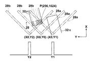
ステージ14の走査方向に沿って上流側(以下、単に「上流側」ということがある。)の端縁部には、X軸の方向に向かって開く「く」の字型に形成されたスリット28が、等間隔で9本形成されている。各スリット28は、上流側に位置するスリット28aと下流側に位置するスリット28bとからなっている。スリット28aとスリット28bとは互いに直交するとともに、X軸に対してスリット28aは−45度、スリット28bは+45度の角度を有している。ステージ14内部の各スリット28の下方の位置には、それぞれ単一セル型の光検出器(図示せず)が組み込まれている。各光検出器は、後述する使用画素選択処理を行う演算装置(図示せず)に接続されている。
A slit formed in a “<” shape that opens in the direction of the X-axis at the upstream edge (hereinafter sometimes simply referred to as “upstream”) along the scanning direction of the
スキャナ24は、図2および図3(B)に示すように、2行5列の略マトリックス状に配列された10個の露光ヘッド30を備えている。なお、以下において、m行目のn列目に配列された個々の露光ヘッドを示す場合は、露光ヘッド30mnと表記する。
As shown in FIGS. 2 and 3B, the
各露光ヘッド30は、後述する内部のデジタル・マイクロミラー・デバイス(DMD)36の画素列方向が走査方向と所定の設定傾斜角度θをなすように、スキャナ24に取り付けられている。したがって、各露光ヘッド30による露光エリア32は、走査方向に対して傾斜した矩形状のエリアとなる。ステージ14の移動に伴い、感光材料12の露光面上には露光ヘッド30ごとに帯状の露光済み領域34が形成される。なお、以下において、m行目のn列目に配列された個々の露光ヘッドによる露光エリアを示す場合は、露光エリア32mnと表記する。
Each
また、図3の(A)および(B)に示すように、各露光ヘッド30は、帯状の露光済み領域34のそれぞれが、隣接する露光済み領域34と部分的に重なるように配置されている。このため、たとえば1行目の露光エリア3211と露光エリア3212との間の露光できない部分は、2行目の露光エリア3221により露光することができる。
Further, as shown in FIGS. 3A and 3B, each
なお、上記の9個のスリット28の位置は、隣接する露光済み領域34間の重複部分の中心位置と略一致させられている。また、各スリット28の大きさは、露光済み領域34間の重複部分の幅を十分覆う大きさとされている。
Note that the positions of the nine
露光ヘッド30の各々は、図4および図5に示すように、入射された光を画像データに応じて各画素部ごとに変調する空間光変調素子として、米国テキサス・インスツルメンツ社製のDMD36を備えている。このDMD36は、データ処理部とミラー駆動制御部とを備えたコントローラに接続されている。このコントローラのデータ処理部では、入力された画像データに基づいて、各露光ヘッド30ごとに、DMD36上の使用領域内の各マイクロミラーを駆動制御する制御信号を生成する。また、ミラー駆動制御部では、画像データ処理部で生成した制御信号に基づいて、各露光ヘッド30ごとにDMD36の各マイクロミラーの反射面の角度を制御する。
As shown in FIGS. 4 and 5, each of the exposure heads 30 includes a
図4に示すように、DMD36の光入射側には、光ファイバの出射端部(発光点)が露光エリア32の長辺方向と一致する方向に沿って一列に配列されたレーザ出射部を備えたファイバアレイ光源38、ファイバアレイ光源38から出射されたレーザ光を補正してDMD上に集光させるレンズ系40、このレンズ系40を透過したレーザ光をDMD36に向けて反射するミラー42がこの順に配置されている。なお図4では、レンズ系40を概略的に示してある。
As shown in FIG. 4, on the light incident side of the
上記レンズ系40は、図5に詳しく示すように、ファイバアレイ光源38から出射されたレーザ光を平行光化する1対の組合せレンズ44、平行光化されたレーザ光の光量分布が均一になるように補正する1対の組合せレンズ46、および光量分布が補正されたレーザ光をDMD36上に集光する集光レンズ48で構成されている。
As shown in detail in FIG. 5, the
また、DMD36の光反射側には、DMD36で反射されたレーザ光を感光材料12の露光面上に結像するレンズ系50が配置されている。レンズ系50は、DMD36と感光材料12の露光面とが共役な関係となるように配置された、2枚のレンズ52および54からなる。
Further, on the light reflection side of the
本実施形態では、ファイバアレイ光源38から出射されたレーザ光は、実質的に5倍に拡大された後、DMD36上の各マイクロミラーからの光線が上記のレンズ系50によって約5μmに絞られるように設定されている。
In the present embodiment, the laser light emitted from the fiber
DMD36は図6に示すように、SRAMセル(メモリセル)56上に、各々画素(ピクセル)を構成する多数のマイクロミラー58が格子状に配列されてなるミラーデバイスである。本実施形態では、1024列×768行のマイクロミラー58が配されてなるDMD36を使用するが、このうちDMD36に接続されたコントローラにより駆動可能すなわち使用可能なマイクロミラー58は、1024列×256行のみであるとする。DMD36のデータ処理速度には限界があり、使用するマイクロミラー数に比例して1ライン当りの変調速度が決定されるので、このように一部のマイクロミラーのみを使用することにより1ライン当りの変調速度が速くなる。各マイクロミラー58は支柱に支えられており、その表面にはアルミニウム等の反射率の高い材料が蒸着されている。なお、本実施形態では、各マイクロミラー58の反射率は90%以上であり、その配列ピッチは縦方向、横方向ともに13.7μmである。SRAMセル56は、ヒンジおよびヨークを含む支柱を介して通常の半導体メモリの製造ラインで製造されるシリコンゲートのCMOSのものであり、全体はモノリシック(一体型)に構成されている。
As shown in FIG. 6, the
DMD36のSRAMセル56に、所望の2次元パターンを構成する各点の濃度を2値で表した画像信号が書き込まれると、支柱に支えられた各マイクロミラー58が、対角線を中心としてDMD36が配置された基板側に対して±α度(たとえば±10度)のいずれかに傾く。図7の(A)は、マイクロミラー58がオン状態である+α度に傾いた状態を示し、図7の(B)は、マイクロミラー58がオフ状態である−α度に傾いた状態を示す。したがって、画像信号に応じて、DMD36の各ピクセルにおけるマイクロミラー58の傾きを、図6に示すように制御することによって、DMD36に入射したレーザ光Bはそれぞれのマイクロミラー58の傾き方向へ反射される。
When an image signal representing the density of each point constituting a desired two-dimensional pattern in binary is written in the
なお図6には、DMD36の一部を拡大し、各マイクロミラー58が+α度または−α度に制御されている状態の一例を示す。それぞれのマイクロミラー58のオンオフ制御は、DMD36に接続されたコントローラによって行われる。また、オフ状態のマイクロミラー58で反射したレーザ光Bが進行する方向には、光吸収体(図示せず)が配置されている。
FIG. 6 shows an example in which a part of the
ファイバアレイ光源38は、図8に示すように、複数(たとえば14個)のレーザモジュール60を備えており、各レーザモジュール60には、マルチモード光ファイバ62の一端が結合されている。マルチモード光ファイバ62の他端には、マルチモード光ファイバ62より小さいクラッド径を有するマルチモード光ファイバ64が結合されている。図9に詳しく示すように、マルチモード光ファイバ64のマルチモード光ファイバ62と反対側の端部は走査方向と直交する方向に沿って7個並べられ、それが2列に配列されてレーザ出射部66が構成されている。
As shown in FIG. 8, the fiber
マルチモード光ファイバ64の端部で構成されるレーザ出射部66は、図9に示すように、表面が平坦な2枚の支持板68に挟み込まれて固定されている。また、マルチモード光ファイバ64の光出射端面には、その保護のために、ガラス等の透明な保護板が配置されるのが望ましい。マルチモード光ファイバ64の光出射端面は、光密度が高いため集塵しやすく劣化しやすいが、上述のような保護板を配置することにより、端面への塵埃の付着を防止し、また劣化を遅らせることができる。
As shown in FIG. 9, the
以下、図10から13を用いて、本実施形態の露光装置10における使用画素指定処理の例について説明する。
Hereinafter, an example of the use pixel designation process in the
本実施形態では、露光装置10により2重露光処理を行うこととし、各露光ヘッド30すなわち各DMD36の設定傾斜角度としては、露光ヘッド30の取付角度誤差等がない理想的な状態であれば、使用可能な1024列×256行のマイクロミラー58を使用してちょうど2重露光となる角度θidealを採用するものとする。この角度θidealは、N重露光の数N、使用可能なマイクロミラー58の各画素列をなすマイクロミラー58の個数s、使用可能なマイクロミラー58の画素列方向の画素ピッチp、および走査方向と直交する方向に沿った使用可能なマイクロミラー58の画素列ピッチδに対し、
により与えられる。本実施形態におけるDMD36は、上記のとおり、縦横の配置ピッチが等しい多数のマイクロミラー58が矩形格子状に配されたものであるので、
であり、上記の式(1)は、
となる。本実施形態では、上記のとおりs=256、N=2であるので、式(3)より、角度θidealは約0.45度である。露光装置10は、各露光ヘッド30すなわち各DMD36の取付角度がこの角度θidealとなるように、初期調整されているものとする。
It becomes. In this embodiment, since s = 256 and N = 2 as described above, the angle θ ideal is about 0.45 degrees from the equation (3). It is assumed that the
図10は、上記のように初期調整された露光装置10において、2つの露光ヘッド(一例として露光ヘッド3012と3021)のX軸方向に関する相対位置の、理想的な状態からのずれの影響により、露光面上のパターンに生じるむらの例を示した説明図である。このX軸方向に関する相対位置のずれは、露光ヘッド間の相対位置の微調整が困難であるために生じ得るものである。
FIG. 10 shows the influence of deviation of the relative positions of the two exposure heads (for example, exposure heads 30 12 and 30 21 ) in the X-axis direction from the ideal state in the
以下の図面および説明においては、露光面上における各露光エリア32中の第m番目の光点行をr(m)、露光面上における第n番目の光点列をc(n)、第m行第n列の光点をP(m,n)とそれぞれ表記するものとする。図10の上段部分は、ステージ14を静止させた状態で感光材料12の露光面上に投影される、露光ヘッド3012と3021が有するDMD36の使用可能なマイクロミラー58からの光点群のパターンを示した図である。図10の下段部分は、上段部分に示したような光点群のパターンが現れている状態でステージ14を移動させて連続露光を行った際に、露光面上に形成される露光パターンの状態を、露光エリア3212と3221のヘッド間つなぎ領域およびその周辺部について示したものである。なお、図10では、説明の便宜のため、使用可能なマイクロミラー58の1本おきの画素列からなる画素列群Aによる露光パターンと、残りの画素列からなる画素列群Bによる露光パターンを分けて示してあるが、実際の露光面上における露光パターンは、これら2つの露光パターンを重ね合わせたものである。
In the following drawings and description, the mth light spot row in each
図10の例では、上記したX軸方向に関する露光ヘッド3012と3021の間の相対位置の、理想的な状態からのずれの結果として、画素列群Aによる露光パターンと画素列群Bによる露光パターンとの双方で、露光エリア3212と3221のヘッド間つなぎ領域において、理想的な2重露光の状態よりも露光が冗長な部分が生じてしまっている。
In the example of FIG. 10, as a result of the deviation of the relative position between the exposure heads 30 12 and 30 21 in the X-axis direction from the ideal state, the exposure pattern by the pixel column group A and the pixel column group B in both the exposure pattern, the head connected region between the
上記のような露光面上のヘッド間つなぎ領域に現れるむらを軽減するために、本実施形態では、上述のスリット28および光検出器の組を用いて、露光ヘッド3012と3021からの光点群のうち、描画面上においてヘッド間つなぎ領域を構成する光点のいくつかについて、その描画面上における位置を検出する。その位置検出結果に基づいて、光検出器に接続された演算装置において、露光ヘッド3012と3021のヘッド間つなぎ領域を構成する光点に対応するマイクロミラーのうち、実際に本露光処理に使用するマイクロミラーを選択する、つなぎ領域使用画素の選択処理を行う。
In order to reduce the unevenness appearing in the connecting area between the heads on the exposure surface as described above, in the present embodiment, the light from the exposure heads 30 12 and 30 21 is used by using the above-described combination of the
まず、図11および12を用いて、スリット28および光検出器の組を用いた光点の位置検出手法について説明する。図11は、図10と同様の露光エリア3212および3221と、対応するスリット28との位置関係を示した上面図である。すでに述べたように、スリット28の大きさは、露光ヘッド3012と3021による露光済み領域34間の重複部分の幅を十分覆う大きさ、すなわちヘッドつなぎ領域を十分覆う大きさとされている。
First, with reference to FIGS. 11 and 12, a method for detecting the position of a light spot using a set of a
図12は、一例として露光エリア3221の光点P(256,1024)の位置を検出する際の検出手法を説明した上面図である。まず、P(256,1024)を点灯させた状態で、ステージ14をゆっくり移動させてスリット28をY軸方向に沿って相対移動させ、光点P(256,1024)が上流側のスリット28aと下流側のスリット28bの間に来るような任意の位置に、スリット28を位置させる。このときのスリット28aとスリット28bとの交点の座標を(X0,Y0)とする。この座標(X0,Y0)の値は、ステージ14に与えられた駆動信号が示す上記の位置までのステージ14の移動距離、および、既知であるスリット28のX軸方向位置から決定され、記録される。
Figure 12 is a top view for explaining a detection method of detecting the position of a point P of the exposure area 32 21 as an example (256, 1024). First, in a state where P (256, 1024) is lit, the
次に、ステージ14を移動させ、スリット28をY軸に沿って図12における右方に相対移動させる。そして、図12において二点鎖線で示すように、光点P(256,1024)の光が左側のスリット28bを通過して光検出器で検出されたところでステージ14を停止させる。このときのスリット28aとスリット28bとの交点の座標を(X0,Y1)として記録する。
Next, the
今度はステージ14を反対方向に移動させ、スリット28をY軸に沿って図12における左方に相対移動させる。そして、図12において二点鎖線で示すように、光点P(256,1024)の光が右側のスリット28aを通過して光検出器で検出されたところでステージ14を停止させる。このときのスリット28aとスリット28bとの交点の座標を(X0,Y2)として記録する。
This time, the
以上の測定結果から、光点P(256,1024)の座標(X,Y)を、X=X0+(Y1−Y2)/2、Y=(Y1+Y2)/2の計算により決定する。 From the above measurement results, the coordinates (X, Y) of the light spot P (256, 1024) are determined by the calculation of X = X0 + (Y1-Y2) / 2, Y = (Y1 + Y2) / 2.
つなぎ領域使用画素の選択に際しては、図10の例では、まず、露光エリア3212の光点P(256,1)の位置を、上記のスリット28と光検出器の組により検出する。続いて、露光エリア3221の光点行r(256)上の光点の位置を、光点P(256,1024)、P(256,1023)・・・と順番に検出していき、露光エリア3212の光点P(256,1)よりも大きいX座標を示す光点P(256,n)が検出されたところで、検出動作を終了する。そして、露光エリア3221の光点列c(n+1)からc(1024)を構成する光点に対応するマイクロミラーを、本露光に使用しないマイクロミラーとして特定する。たとえば、図10の例において露光エリア3221の光点P(256,1020)が露光エリア3212の光点P(256,1)よりも大きいX座標を示し、その露光エリア3221の光点P(256,1020)が検出されたところで検出動作が終了したとすると、図13において斜線で覆われた部分70に相当する、露光エリア3221の光点列c(1021)からc(1024)を構成する光点に対応するマイクロミラーが、本露光に使用しないマイクロミラーとして特定される。
In the selection of the connecting region use pixel, in the example of FIG. 10, first, the position of the
次に、N重露光の数Nに対して、露光エリア3212の光点P(256,N)の位置が検出される。本実施形態ではN=2であるので、光点P(256,2)の位置が検出される。続いて、露光エリア3221の光点列のうち、上記で本露光に使用しないマイクロミラーに対応する光点列として特定されたものを除く最も右側の光点列c(1020)を構成する光点の位置を、光点P(1,1020)から順番にP(1,1020)、P(2,1020)・・・と検出していき、露光エリア3212の光点P(256,2)よりも大きいX座標を示す光点P(m,1020)が検出されたところで、検出動作を終了する。その後、光検出器に接続された演算装置において露光エリア3212の光点P(256,2)のX座標と、露光エリア3221の光点P(m,1020)およびP(m−1,1020)のX座標とが比較され、露光エリア3221の光点P(m,1020)のX座標の方が露光エリア3212の光点P(256,2)のX座標に近い場合は、露光エリア3221の光点P(1,1020)からP(m−1,1020)に対応するマイクロミラーが、露光エリア3221の光点P(m−1,1020)のX座標の方が露光エリア3212の光点P(256,2)のX座標に近い場合は、露光エリア3221の光点P(1,1020)からP(m−2,1020)に対応するマイクロミラーが、本露光に使用しないマイクロミラーとして特定される。露光エリア3212の光点P(256,N−1)すなわちP(256,1)の位置と、露光エリア3221の次の光点列c(1019)を構成する各光点の位置についても、同様の検出処理およびマイクロミラーの選択処理が行われる。その結果、たとえば、図13において網掛けで覆われた部分72を構成する光点に対応するマイクロミラーが、本露光に使用しないマイクロミラーとして追加特定される。これらの本露光に使用しないものとして特定されたマイクロミラーには、常時、そのマイクロミラーの角度をオフ状態の角度に設定する信号が送られ、それらのマイクロミラーは、実質的に本露光に使用されない。
Next, the number N of the N multiple exposure, the position of the point P of the exposure area 32 12 (256, N) is detected. In this embodiment, since N = 2, the position of the light spot P (256, 2) is detected. Then, among the light spot columns of the
以上のようにして本露光に使用しないマイクロミラーを選択すれば、露光エリア3212と3221のヘッド間つなぎ領域において、理想的な2重露光に対して露光が冗長となる部分および理想的な2重露光に対して露光が不足となる部分の合計を最小とすることができ、図13の下段に示すように、理想的状態に極めて近い均一な2重露光を実現することができる。
If a micromirror that is not used for the main exposure is selected as described above, in the connection area between the heads of the
なお、上記の例においては、図13において網掛けで覆われた部分72を構成する光点の特定に際し、露光エリア3212の光点P(256,2)のX座標と、露光エリア3221の光点P(m,1020)およびP(m−1,1020)のX座標との比較を行わずに、ただちに、露光エリア3221の光点P(1,1020)からP(m−2,1020)に対応するマイクロミラーを、本露光に使用しないマイクロミラーとして特定することとしてもよい。その場合、ヘッド間つなぎ領域において、理想的な2重露光に対して露光が冗長となる部分が最小になり、かつ、理想的な2重露光に対して露光が不足となる部分が生じないようなマイクロミラーを、実際に使用するマイクロミラーとして選択することができる。あるいは、露光エリア3221の光点P(1,1020)からP(m−1,1020)に対応するマイクロミラーを、本露光に使用しないマイクロミラーとして特定することとしてもよい。その場合、ヘッド間つなぎ領域において、理想的な2重露光に対して露光が不足となる部分が最小になり、かつ、理想的な2重露光に対して露光が冗長となる部分が生じないようなマイクロミラーを、実際に使用するマイクロミラーとして選択することができる。あるいは、露光面上のヘッド間つなぎ領域において、理想的な2重描画に対して露光が冗長となる部分の光点数と、理想的な2重描画に対して露光が不足となる部分の光点数とが等しくなるように、実際に使用するマイクロミラーを選択することとしてもよい。
In the example above, the X-coordinate upon the specific light spot constituting the
続いて、上記に説明した本実施形態の露光装置10の変更例における画素指定処理の例を、図14および15を用いて説明する。この例は、図10から13を用いて説明した画素指定処理の例において考慮された、露光ヘッド3212と3221の間の平行な相対位置のずれに加えて、各露光ヘッド3212および3221の取付角度誤差ならびに露光ヘッド3212と3221の間の相対取付角度のずれも考慮し、それらの影響を最小限に抑えて、露光面上における解像性や濃度のむらをさらに軽減する処理の例である。
Next, an example of pixel designation processing in the modification example of the
この変更例では、露光装置10は、上記の実施形態と同様、2重露光処理を行うものであるが、各露光ヘッド30すなわち各DMD36の設定傾斜角度としては、上記の式(1)を満たす理想的な角度θidealよりも若干大きい角度、たとえば0.50度程度の角度θを採用する。これは、各露光ヘッド30の取付角度の微調整は困難であるが、取付角度に多少の誤差が生じても、各露光ヘッド30の実際の取付角度が理想的な角度θidealを下回らないようにするためである。露光装置10は、調整可能な範囲内で、各露光ヘッド30すなわち各DMD36の取付角度がこの設定傾斜角度θに近い角度となるように、初期調整されているものとする。
In this modification, the
図14は、上記のように初期調整された露光装置10において、2つの露光ヘッド(一例として露光ヘッド3012と3021)のX軸方向に関する相対位置のずれ、ならびに各露光ヘッド3012と3021の取付角度誤差および相対的な角度ずれの影響により、露光面上のパターンに生じるむらの例を示した説明図である。
14, in the initial adjusted
図14の例では、図10の例と同様の、X軸方向に関する露光ヘッド3012と3021の相対位置のずれの結果として、画素列群Aによる露光パターンと画素列群Bによる露光パターンとの双方で、露光エリア3212と3221のヘッド間つなぎ領域において、理想的な2重露光の状態よりも露光が冗長な部分74が生じ、これが濃度むらを引き起こしている。加えて、図14の例では、各露光ヘッドの設定傾斜角度θを上記の式(1)を満たす角度θidealよりも若干大きくしたこと、および、各露光ヘッドの取付角度の微調整が困難であるために、実際の取付角度が上記の設定傾斜角度θからもわずかにずれてしまったことの結果として、露光面上のヘッド間つなぎ領域以外の領域でも、画素列群Aによる露光パターンと画素列群Bによる露光パターンの双方で、各画素列の端部に対応する部分すなわち画素列間のつなぎの部分において、理想的な2重露光の状態よりも露光が冗長な部分76が生じ、これがさらなる濃度むらを引き起こしている。
In the example of FIG. 14, the exposure pattern by the pixel column group A and the exposure pattern by the pixel column group B are the same as the result of the relative positional shift between the exposure heads 30 12 and 30 21 in the X-axis direction, as in the example of FIG. In both cases, in the connection area between the heads of the
この変更例では、まず、上記の各露光ヘッド3012と3021の取付角度誤差および相対取付角度のずれの影響による濃度むらを軽減するための使用画素選択処理を行う。具体的には、上述のスリット28および光検出器の組を用いて、露光ヘッド3012と3021のそれぞれについて、露光面上に投影された画素列の実傾斜角度θ’を特定し、光検出器に接続された演算装置において、その実傾斜角度θ’に基づいて実際に本露光処理に使用するマイクロミラーを選択する。実傾斜角度θ’の特定は、たとえば、露光ヘッド3012については図14の露光エリア3212内の光点P(1,1)とP(256,1)の位置を、露光ヘッド3021については露光エリア3221内の光点P(1,1024)とP(256,1024)の位置を、それぞれ上記のスリット28と光検出器の組により検出し、それらの光点を結ぶ直線の傾斜角度を、演算装置において計算することにより行われる。
In this modification, first, the use pixel selection process for reducing the uneven density due to the influence of the mounting angle error and relative mounting angle of deviation of each exposure heads 30 12 of the 30 21. Specifically, the actual inclination angle θ ′ of the pixel row projected on the exposure surface is specified for each of the exposure heads 30 12 and 30 21 using the above-described combination of the
そのようにして特定された実傾斜角度θ’を用いて、光検出器に接続された演算装置は、
の関係を満たす値tに最も近い自然数Tを、露光ヘッド3012と3021のそれぞれについて導出し、DMD36上の(T+1)行目から256行目のマイクロミラーを、本露光に使用しないマイクロミラーとして特定する処理を行う。たとえば、露光ヘッド3012についてはT=254、露光ヘッド3021についてはT=255が導出されたとすると、図15において斜線で覆われた部分78および80を構成する光点に対応するマイクロミラーが、本露光に使用しないマイクロミラーとして特定される。これにより、露光エリア3212と3221のヘッド間つなぎ領域以外の各領域において、理想的な2重露光に対して露光が冗長となる部分および理想的な2重露光に対して露光が不足となる部分の合計が最小となるようになすことができる。
Is derived for each of the exposure heads 30 12 and 30 21 , and the micromirrors on the
ここで、上記の値tに最も近い自然数を導出することに代えて、値t以上の最小の自然数を導出することとしてもよい。その場合、露光エリア3212と3221のヘッド間つなぎ領域以外の各領域において、理想的な2重露光に対して露光が冗長となる部分が最小になり、かつ、理想的な2重露光に対して露光が不足となる部分が生じないようになすことができる。あるいは、値t以下の最大の自然数を導出することとしてもよい。その場合、露光エリア3212と3221のヘッド間つなぎ領域以外の各領域において、理想的な2重露光に対して露光が不足となる部分が最小になり、かつ、理想的な2重露光に対して露光が冗長となる部分が生じないようになすことができる。ヘッド間つなぎ領域以外の各領域において、理想的な2重描画に対して露光が冗長となる部分の光点数と、理想的な2重描画に対して露光が不足となる部分の光点数とが等しくなるように、本露光に使用しないマイクロミラーを特定することとしてもよい。
Here, instead of deriving the natural number closest to the above value t, the minimum natural number greater than or equal to the value t may be derived. In that case, in each area other than the connection area between the heads of the
その後、図15において斜線で覆われた部分78および80を構成する光点以外の光点に対応するマイクロミラーに関して、図10から13を用いて説明した上記の使用画素選択処理と同様の処理がなされ、図15において斜線で覆われた部分82および網掛けで覆われた部分84を構成する光点に対応するマイクロミラーが、本露光に使用しないマイクロミラーとして追加特定される。これらの本露光に使用しないものとして特定されたマイクロミラーには、常時、そのマイクロミラーの角度をオフ状態の角度に設定する信号が送られ、それらのマイクロミラーは、実質的に本露光に使用されない。
Thereafter, with respect to the micromirror corresponding to the light spots other than the light spots constituting the
上記の変更例によれば、ヘッド間つなぎ領域とそれ以外の領域を含む描画面の全体に亘って解像性や濃度のむらを軽減した、均一な2重露光を行うことができる。 According to the above modification, uniform double exposure can be performed with reduced resolution and uneven density over the entire drawing surface including the head-to-head connection area and the other areas.
以上、本発明の描画装置の1つの実施形態およびその変更例について詳細に説明したが、上記は例示に過ぎず、本発明の範囲を逸脱することなく種々の変更が可能である。 As mentioned above, although one embodiment of the drawing apparatus of this invention and its modification example were demonstrated in detail, the above is only an illustration and various changes are possible without deviating from the scope of the present invention.
たとえば、上記の実施形態および変更例では、露光面上の光点の位置を検出するための手段として、スリット28と単一セル型の光検出器の組を用いたが、これに限られずいかなる形態のものを用いてもよく、たとえば2次元検出器等を用いてもよい。
For example, in the above-described embodiment and modification, the
また、上記の実施形態および変更例では、スリット28と光検出器の組による光点の位置検出結果に基づいて、光検出器に接続された演算装置により、本露光に実際に使用するマイクロミラーを選択する形態としたが、たとえばすべての使用可能なマイクロミラーを用いた参照露光を行い、参照露光結果の目視による解像性や濃度のむらの確認等により、操作者が使用するマイクロミラーを手動で指定する形態も、本発明の範囲に含まれるものである。
In the embodiment and the modification described above, the micro mirror actually used for the main exposure is calculated by the arithmetic unit connected to the light detector based on the position detection result of the light spot by the combination of the
さらに、上記の実施形態の別の変更例として、各露光ヘッド30のDMD36が有する使用可能なマイクロミラーのうち、(N−1)本おきの画素列を構成するマイクロミラー、または全画素行数の1/N本に相当する互いに隣接する画素行の群を構成するマイクロミラーのみを使用して、参照露光を行い、ヘッド間つなぎ領域を構成する光点に対応するマイクロミラーのうち参照露光に使用されたものの中から、理想的な1重露光に近い状態を実現できるように、本露光に使用しないマイクロミラーを特定することとしてもよい。
Furthermore, as another modification of the above-described embodiment, among the usable micromirrors of the
図16は、(N−1)本おきの画素列を構成するマイクロミラーのみを使用して参照露光を行う形態の一例を示した説明図である。この例では、本露光は2重露光とするものとし、したがってN=2である。まず、図16に実線で示した、X軸方向に関して隣接する2つの露光ヘッド(一例として露光ヘッド3012と3021)の奇数列目の光点列に対応するマイクロミラーのみを使用して、参照露光を行い、参照露光結果をサンプル出力する。出力された参照露光結果に対し、操作者は、目視により解像性や濃度のむらを確認したり、実傾斜角度を推定したりすることで、ヘッド間つなぎ領域において解像性や濃度のむらを最小限に抑えた本露光が実現できるように、本露光において使用するマイクロミラーを指定することができる。たとえば、図16に斜線で覆って示す部分86および網掛けで示す部分88内の光点列に対応するもの以外のマイクロミラーが、奇数列目の画素列を構成するマイクロミラーのうち本露光において実際に使用されるものとして指定され得る。偶数列目の画素列については、別途同様に参照露光を行って、本露光に使用するマイクロミラーを指定してもよいし、奇数列目の画素列に対するパターンと同一のパターンを適用してもよい。このようにして本露光に使用するマイクロミラーを指定することにより、奇数列目および偶数列目の双方のマイクロミラー列を使用した本露光では、ヘッド間つなぎ領域において理想的な2重露光に近い状態が実現できる。なお、参照露光結果の分析は、操作者の目視によるものに限らず、機械的な分析であってもよい。なお、図16での説明は、露光ヘッド3012と露光ヘッド3021の関係が、図16に示したように露光ヘッド3012の奇数列と露光ヘッド3021の奇数列が連続する関係にあるので、両方の露光ヘッドについて奇数列の間引き参照露光としたが、これに限らず、一方の露光ヘッドについては偶数列の間引き参照露光とし、他方の露光ヘッドについては奇数列の間引き参照露光とするようにしてもよい。
FIG. 16 is an explanatory diagram showing an example of a form in which reference exposure is performed using only micromirrors that constitute every (N−1) pixel rows. In this example, the main exposure is assumed to be double exposure, and therefore N = 2. First, using only micromirrors corresponding to the odd-numbered light spot rows of two exposure heads adjacent to each other in the X-axis direction (for example, exposure heads 30 12 and 30 21 ) shown by a solid line in FIG. Reference exposure is performed, and a reference exposure result is output as a sample. For the output reference exposure results, the operator can visually check the resolution and density unevenness, and estimate the actual tilt angle to minimize the resolution and density unevenness in the head-to-head connection area. The micromirror used in the main exposure can be designated so that the main exposure can be realized to a limited extent. For example, in the main exposure, micromirrors other than those corresponding to the light spot columns in the
図17は、X軸方向に関して隣接する2つの露光ヘッド(一例として露光ヘッド3012と3021)について、それぞれ全画素行数の1/N本に相当する互いに隣接する画素行の群を構成するマイクロミラーのみを使用して参照露光を行う形態の一例を示した説明図である。この例では、本露光は2重露光とするものとし、したがってN=2である。まず、図17に実線で示した1行目から128(=256/2)行目の光点に対応するマイクロミラーのみを使用して、参照露光を行い、参照露光結果をサンプル出力する。出力された参照露光結果に対し、操作者は、目視により解像性や濃度のむらを確認したり、実傾斜角度を推定したりすることで、ヘッド間つなぎ領域において解像性や濃度のむらを最小限に抑えた本露光が実現できるように、本露光において使用するマイクロミラーを指定することができる。たとえば、図17に斜線で覆って示す部分90および網掛けで示す部分92内の光点列に対応するもの以外のマイクロミラーが、1行目から128行目のマイクロミラーのうち本露光において実際に使用されるものとして指定され得る。129行目から256行目のマイクロミラーについては、別途同様に参照露光を行って、本露光に使用するマイクロミラーを指定してもよいし、1行目から128行目のマイクロミラーに対するパターンと同一のパターンを適用してもよい。このようにして本露光に使用するマイクロミラーを指定することにより、全体のマイクロミラーを使用した本露光では、ヘッド間つなぎ領域において理想的な2重露光に近い状態が実現できる。なお、参照露光結果の分析は、操作者の目視によるものに限らず、機械的な分析であってもよい。
FIG. 17 shows a group of adjacent pixel rows corresponding to 1 / N of the total number of pixel rows for two exposure heads adjacent to each other in the X-axis direction (for example, exposure heads 30 12 and 30 21 ). It is explanatory drawing which showed an example of the form which performs reference exposure using only a micromirror. In this example, the main exposure is assumed to be double exposure, and therefore N = 2. First, reference exposure is performed using only micromirrors corresponding to the light spots in the first to 128 (= 256/2) rows indicated by the solid line in FIG. 17, and the reference exposure results are output as samples. With respect to the output reference exposure result, the operator can visually check the resolution and density unevenness or estimate the actual tilt angle to minimize the resolution and density unevenness in the head-to-head connection area. The micromirror used in the main exposure can be designated so that the main exposure can be realized to the limit. For example, micromirrors other than those corresponding to the light spot columns in the
以上の実施形態および変更例は、いずれも本露光を2重露光とする場合について説明したが、これに限られず、1重露光以上のいかなるN重露光としてもよい。ただし、描画面上に残留する2次元パターンの解像性や濃度のむらを、埋め合わせの効果によりさらに軽減するためには、2重露光以上の多重露光とすることが好ましい。特に3重露光から7重露光程度とすることにより、高い解像性の確保と、解像性および濃度のむらの軽減の効果のバランスがよい露光とすることができる。 In the above embodiments and modified examples, the case where the main exposure is the double exposure has been described. However, the present invention is not limited to this, and any N double exposure or more than the single exposure may be used. However, in order to further reduce the non-uniformity in resolution and density of the two-dimensional pattern remaining on the drawing surface, it is preferable to perform multiple exposure of double exposure or more. In particular, by setting the exposure to about 3 to 7 exposures, it is possible to achieve an exposure with a good balance between ensuring high resolution and reducing resolution and density unevenness.
また、上記の実施形態および変更例に係る露光装置において、ヘッド間つなぎ領域における使用画素の選択は、上記の図13の例のように、そのヘッド間つなぎ領域に関与する2つの露光ヘッドのうち一方の露光ヘッドにおいてのみ、いくつかの画素を不使用とする形態でもよいし、双方の露光ヘッドが不使用画素を分担するような形態であってもよい。 Further, in the exposure apparatus according to the embodiment and the modification example, the selection of the use pixel in the head-to-head connection region is performed by selecting one of the two exposure heads involved in the head-to-head connection region as in the example of FIG. Only one exposure head may be configured such that some pixels are not used, or both exposure heads may share unused pixels.
ここで、上記のような露光装置において、参照露光結果に基づいて、使用するマイクロミラーを指定する方法についての一例を説明する。 Here, an example of a method for designating a micromirror to be used based on the reference exposure result in the above-described exposure apparatus will be described.
具体的には、2つの露光ヘッド(一例として露光ヘッド3012と3021)のX軸方向に関する相対位置の、理想的な状態からのずれ量を計測し、その計測したずれ量に基づいて使用するマイクロミラーを指定する。まずは、上記ずれ量を計測する方法について説明する。 Specifically, the amount of deviation from the ideal state of the relative position in the X-axis direction of two exposure heads (for example, exposure heads 30 12 and 30 21 ) is measured, and used based on the measured amount of deviation. Specifies the micromirror to be used. First, a method for measuring the deviation amount will be described.
上記ずれ量を計測する際には、たとえば、図16で説明したように、露光ヘッド3012および露光ヘッド3021の(N−1)本おきの画素列を構成するマイクロミラーのみを使用して、X軸方向に延びる直線を露光する。つまり、露光ヘッド3012および露光ヘッド3021の各画素列を構成するマイクロミラーにより露光される露光点がX軸方向に並ぶように露光を行う。なお、上記のような(N−1)本おきの画素列を構成するマイクロミラーのみを使用する露光方法を以下「間引き参照露光」という。
When measuring the deviation amount, for example, as described in FIG. 16, the
そして、上記のようにX軸方向に延びる直線を露光する際、露光ヘッド3021については、所定の画素数(以下「所定のスキマ画像」という。)に対応したマイクロミラーを使用しないようにして露光を行う。 Then, when exposing a straight line extending in the X-axis direction as described above, the exposure head 30 21 a predetermined number of pixels (hereinafter referred to as "predetermined gap image".) To not to use the micro mirrors corresponding Perform exposure.
図18に、上記のようにして露光したX軸方向に延びる直線の一部を示す。なお、図18においては、露光ヘッド3021と露光ヘッド3012とで重複または不足して露光される可能性があると想定される領域近傍の直線を示している。そして、図18における直線L21が露光ヘッド3021より露光される直線であり、直線L12が露光ヘッド3012により露光される直線であり、直線Leが所定のスキマ画像に対応したマイクロミラーにより露光されるべき直線を示している(実際には露光されないので以下「間隔Le」という)。
FIG. 18 shows a part of a straight line extending in the X-axis direction exposed as described above. In FIG. 18, a straight line in the vicinity of a region that is assumed to be exposed by overlapping or
そして、上記のように所定のスキマ画像に対応したマイクロミラーを使用せずに露光を行うとともに、露光ヘッド3012または露光ヘッド3021によって、図19に示すような、リファレンススケールLsを露光する。リファレンススケールLsとは、図19に示すように、露光ヘッド3012または露光ヘッド3021の画素列を構成するマイクロミラーにより露光されるX軸方向に延びる直線であって、n個、n+1個、n+2個、n+3個、n−1個、n−2個およびn−3個の露光点(画素数)に対応する間隔L(n)、L(n+1)、L(n+2)、L(n+3)、L(n−1)、L(n−2)およびL(n−3)を、所定数の露光点毎にX軸方向に並べた直線である。なお、リファレンススケールLsは、露光ヘッド3012または露光ヘッド3021のどちらで露光してもよく、両方の露光ヘッドで露光するようにしてもよい。また、図18に示す直線L21または直線L12の一部にリファレンススケールLsを露光するようにしてもよいし、上記直線L21および直線L12とは別個に露光するようにしてもよい。また、このレファレンススケールLsも間引き参照露光によって露光される。
Then, performs exposure without using a micromirror corresponding to a predetermined gap image as described above, the
そして、リファレンススケールLsにおける間隔L(n)の露光点の数nは、所定のスキマ画像に対応したマイクロミラーの数と同じ数に設定されており、間隔Leの長さと間隔Lとを比較することにより上記ずれ量に対応するマイクロミラーの数を計測することができる。 The number n of exposure points at the interval L (n) in the reference scale Ls is set to the same number as the number of micromirrors corresponding to a predetermined gap image, and the length of the interval Le is compared with the interval L. As a result, the number of micromirrors corresponding to the amount of deviation can be measured.
たとえば、間隔Leの長さが間隔L(n)と同じ長さであれば、上記ずれ量は0である。そして、間隔Leの長さが間隔L(n−3)と同じ長さであれば、上記ずれ量に対応するマイクロミラー数は3個である。したがって、露光ヘッド3012の露光領域に対して、露光ヘッド3221の露光領域がマイクロミラー3個分重複していることになる。したがって、上記のような場合には、図16における光点P(m,1019)、光点P(m+1,1019)および光点P(m+2,1019)に対応するマイクロミラーを使用しないようにすればよい。
For example, if the length of the interval Le is the same as the length of the interval L (n), the deviation amount is zero. And if the length of the space | interval Le is the same length as the space | interval L (n-3), the number of micromirrors corresponding to the said deviation | shift amount is three. Accordingly, the exposure area of the
なお、たとえば、間隔Leの長さが間隔L(n+2)と同じ長さであれば、上記ずれ量に対応するマイクロミラー数は2個である。つまり、画素列におけるマイクロミラー2個分だけ露光ヘッド3012と露光ヘッド3021とが離れていることになる。上記のような場合には、光点P(m−1,1019)、光点P(m−2,1019)を使用するようにすればよい。
For example, if the length of the interval Le is the same as the length of the interval L (n + 2), the number of micromirrors corresponding to the shift amount is two. That is, the 2 pieces of micromirrors only the
なお、間隔Leの長さと間隔Lの長さの比較は目視で行うようにしてもよいし、所定の計測装置により計測するようにしてもよい。 Note that the comparison between the length of the interval Le and the length of the interval L may be made visually, or may be measured by a predetermined measuring device.
上記のようにして間引き参照露光結果に基づいて、使用するマイクロミラーを指定することができる。 As described above, the micromirror to be used can be designated based on the thinning reference exposure result.
ここで、上記の説明では、露光ヘッド3021および露光ヘッド3012において、使用するマイクロミラーを指定することによって、2つの露光ヘッドのX軸方向についての相対位置のずれの影響による露光パターンのむらをなくす方法について説明したが、上記のように各露光ヘッドにおける使用するマイクロミラーを指定したとしても、たとえば、露光ヘッド3021と露光ヘッド3012による、露光面上への露光タイミングが適切でなければ、露光ヘッド3021により露光される露光パターンと露光ヘッド3012により露光される露光パターンとが、Y軸方向についてずれてしまう。
Here, in the above description, in the
たとえば、露光ヘッド3021および露光ヘッド3012によって、上記のようにX軸方向に延びる直線L21,直線L12をそれぞれ間引き参照露光した場合を考えると、各露光ヘッドの露光タイミングが適切でなければ、図20(A)に示すように、直線L21と直線L12とがY軸方向にずれてしまう。
For example, considering the case where the
したがって、図20(B)に示すように、直線L21と直線L12とがY軸方向にずれることなく接続されるように、露光ヘッド3021および露光ヘッド3012による露光タイミングを制御することが望ましい。
Therefore, as shown in FIG. 20B, the exposure timing by the
具体的には、たとえば、図20(B)の直線L21の右端の露光点に対応するマイクロミラーと直線L12の左端の露光点の対応するマイクロミラーの位置を、上記スリット28と光検出器の組や2次元検出器等を用いて計測し、これらのマイクロミラーのY軸方向の距離を求め、この距離とステージ14の移動速度に基づいて、直線L21と直線L12とがY軸方向にずれることなく接続されるような、露光ヘッド3021および露光ヘッド3012の露光タイミングを求め、その露光タイミングで露光するようにすればよい。
Specifically, for example, the position of the micromirrors of the leftmost exposure point of the micro mirror and the straight line L 12 that corresponds to the right end of the exposure point of the straight line L 21 corresponding FIG. 20 (B), the above-mentioned
また、上記のような方法に限らず、予め設定された露光タイミングで露光ヘッド3021および露光ヘッド3012によって実際に直線L21および直線L12を露光し、この露光された直線L21と直線L12のY軸方向へのずれ量を、所定の計測手段によって測定し、そのずれ量に基づいて、上記予め設定された露光タイミングを調整するようにしてもよい。
Further, not limited to the method as described above, actually exposed linear L 21 and the straight line L 12 by the
また、さらに、露光ヘッド3021と露光ヘッド3012とにおいて、図21に示すように、基準となるマイクロミラーr21,r12(以下「基準マイクロミラー」という。)を予め設定しておき、この基準マイクロミラーr21,r12により露光される露光点rp21,rp12が、予め設定された露光面上におけるY軸方向についての基準線RL上に位置するように、露光ヘッド3021および露光ヘッド3012の露光タイミングを調整するようにしてもよい。
Further, in the
また、上記のようにしてY軸方向についてのずれ量を計測する際、マイクロミラーのビームの走査方向がY軸方向に一致しておらず、ずれがある場合には、所定のマイクロミラーでその走査方向に直線を引き、この直線を基準にして各露光ヘッドの基準マイクロミラーによる露光位置の計測を行うことも考えられる。たとえば、走査方向とX軸方向との間の角度が決まっていれば、その走査方向に対してこの角度の仮想線を設定し、この仮想線に対するずれとして、露光位置の計測を行うこともできる。なお、仮想線にパターンの位置および角度を合わせこむように粗調整を行うようにしてもよい。 Further, when measuring the deviation amount in the Y-axis direction as described above, if the scanning direction of the micromirror beam does not coincide with the Y-axis direction, and there is a deviation, the predetermined micromirror It is also conceivable to draw a straight line in the scanning direction and measure the exposure position by the reference micromirror of each exposure head with reference to this straight line. For example, if the angle between the scanning direction and the X-axis direction is determined, a virtual line having this angle can be set for the scanning direction, and the exposure position can be measured as a deviation from the virtual line. . Note that coarse adjustment may be performed so that the position and angle of the pattern are aligned with the virtual line.
なお、上記基準マイクロミラーとしては、各露光ヘッドのDMDの同じ位置にあるマイクロミラーが指定されるものとし、たとえば、図21のように、直線L21の左端の露光点に対応するマイクロミラーと直線L12の左端の露光点に対応するマイクロミラーとを指定するようにすればよい。また、基準マイクロミラーr21,r12により露光される露光点rp21,rp12が、予め設定された露光面上におけるY軸方向についての基準線RL上に位置するように露光タイミングを調整する方法としては、たとえば、予め設定された露光タイミングで露光ヘッド3021と露光ヘッド3012によって直線L21および直線L12を露光し、基準線RLと露光点rp21および露光rp12との位置関係を所定の測定手段により測定し、その計測された位置関係とステージ14の移動速度とに基づいて、上記のように露光タイミングを調整するようにすればよい。
As the above-mentioned reference micromirror, it is assumed that the micro-mirror at the same position of the DMD of the exposure heads are designated, for example, as shown in FIG. 21, the micro mirrors corresponding to the left end of the exposure point of the straight line L 21 it is sufficient to specify the micro mirrors corresponding to the left end of the exposure point of the straight line L 12. Further, the exposure timing is adjusted so that the exposure points rp 21 and rp 12 exposed by the reference micromirrors r 21 and r 12 are positioned on the reference line RL in the Y-axis direction on the preset exposure surface. As a method, for example, the straight line L 21 and the straight line L 12 are exposed by the
また、上記基準線RLは、露光面上において予め設定していてもよいが、たとえば、所定の露光ヘッドの基準マイクロミラーによる光点を通過する、X軸方向に平行な(走査方向に直交する)直線を基準線RLとして設定し、その他の露光ヘッドの基準マイクロミラーのよる光点が、上記基準線RL上に位置するように露光タイミングを調整するようにしてもよい。なお、上記所定の露光ヘッドとしては、たとえば、図3(B)における露光ヘッド3011を指定するようにすればよい。
The reference line RL may be set in advance on the exposure surface. For example, the reference line RL is parallel to the X-axis direction (perpendicular to the scanning direction) passing through a light spot by a reference micromirror of a predetermined exposure head. ) A straight line may be set as the reference line RL, and the exposure timing may be adjusted so that the light spot by the reference micromirror of the other exposure head is positioned on the reference line RL. As the above-mentioned predetermined exposure head, for example, it may be to specify the
ここで、上記のようにして基準マイクロミラーに対応する光点が基準線RL上に位置するような露光タイミングで露光ヘッド3021および露光ヘッド3012によって露光するようにしても、たとえば、露光ヘッド3021または露光ヘッド3012のDMDの実傾斜角度が設定傾斜角度からずれている場合には、図22に示すように、直線L21および直線L12がX軸方向に対して平行にならない。つまり、露光ヘッド3021により露光される露光パターンおよび露光ヘッド3012により露光される露光パターンが基準マイクロミラーに対応する光点を中心として回転したものになってしまう。
Here, as described above, the
そこで、上記のような基準マイクロミラーに対応する光点を中心とする回転ずれ量を、各露光ヘッド毎に計測し、各露光ヘッドにより露光される露光パターンを表す露光画像データに対し、上記回転ずれ量に応じた回転処理を施すことによって、露光ヘッド3021により露光される露光パターン(たとえば、直線L21)と露光ヘッド3012により露光される露光パターン(たとえば、直線L12)とが、Y軸方向について繋がるようにしてもよい。なお、上記回転ずれ量は、たとえば、露光ヘッド3021および露光ヘッド3012により、図22に示すような直線L21および直線L12を露光し、その露光した直線L21と直線L12のX軸方向に対する角度を所定の計測手段により計測して取得するようにすればよい。また、ここで回転処理とは、露光パターンを表す画像データを回転してもよいし、露光ヘッドの中の各列(たとえば、1列から1024列まで)毎のタイミングを制御することによって回転された露光パターンを露光するようにしてもよい。
Therefore, the amount of rotational deviation about the light spot corresponding to the reference micromirror as described above is measured for each exposure head, and the above rotation is performed on the exposure image data representing the exposure pattern exposed by each exposure head. By performing a rotation process according to the shift amount, an exposure pattern exposed by the exposure head 30 21 (for example, a straight line L 21 ) and an exposure pattern exposed by the exposure head 30 12 (for example, a straight line L 12 ) You may make it connect about a Y-axis direction. Note that the rotational deviation amount is obtained by, for example, exposing a straight line L 21 and a straight line L 12 as shown in FIG. 22 by the
また、上記のように所定の計測手段により角度を実施に計測するのではなく、たとえば、上記のように露光ヘッド3021および露光ヘッド3012の基準マイクロミラーr21,r12に対応する露光点rp21,rp12が、基準線RL上に位置するような露光タイミングで直線L21および直線L12を露光するとともに、この直線L21および直線L12にそれぞれ平行な直線を、Y軸方向についてそれぞれ異なるピッチで多数露光し、この露光パターンに基づいて回転ずれ量を取得するようにしてもよい。具体的には、たとえば、図23に示すように、露光ヘッド3021によって直線L21に平行な直線を45μmピッチで多数露光するとともに、露光ヘッド3012によって直線L12に平行な直線を46μmピッチで多数露光し、露光ヘッド3021により露光される直線の右端の光点とY軸方向についての位置が一致する左端を有する、露光ヘッド3012により露光される直線を求め、その直線が直線L12から何番目の直線かを数え、たとえば、図23に示すように直線L12から3番目の直線である場合には、ノギスの計測原理と同様に、直線L21の右端の光点が基準線RLから3μmずれていると計測するようにすればよい。そして、たとえば、上記ずれを光点rp21を中心とする直線L21の回転角に換算し、その回転角に基づいて上記のように回転処理を露光画像データに施すようにすればよい。
Further, the angle is not actually measured by the predetermined measuring means as described above, but, for example, the exposure points corresponding to the reference micromirrors r 21 and r 12 of the
また、上記説明では、露光ヘッド3021および露光ヘッド3012の基準マイクロミラーr21,r12により露光される露光点rp21,rp12が基準線RL上に位置するように露光タイミングに設定した後、露光ヘッド3021により露光される直線L21および露光ヘッド3012により露光される直線L12のX軸方向に対する回転ずれ量を求め、この回転ずれ量に基づいて露光画像データに回転処理を施すようにしたが、上記露光タイミングの設定と、上記回転処理の順序が逆でもよい。具体的には、予め設定された露光タイミングで、図24に示すように、直線L21および直線L12を露光し、この直線L21および直線L12のX軸方向に対する回転ずれ量を計測してその回転ずれ量に応じた回転処理を露光画像データに施した後、再び、図24(B)に示すように、露光ヘッド21および露光ヘッド12によって直線L21および直線L12を露光し、その露光した直線L21および直線l2と基準線RLとのY軸方向についてのずれ量を計測し、そのずれ量に応じて上記予め設定された露光タイミングを調整することによって、基準線RL上に直線L21および直線L12が基準線RL上に位置するようにしてもよい。
In the above description, the exposure timing is set so that the exposure points rp 21 and rp 12 exposed by the reference micromirrors r 21 and r 12 of the
また、上記のように回転処理は行わずに、露光タイミングのみを調整して、図25に示すように直線L21の右端と直線L12の左端とをY軸方向について一致させるようにしてもよい。具体的には、予め設定された露光タイミングで直線L21と直線L12とを露光し、その直線L21の右端の露光点のY軸方向についての位置と直線L12の左端の光点のY軸方向についての位置とのずれ量を所定の計測手段により計測し、そのずれ量に基づいて、直線L21の右端の露光点のY軸方向についての位置と直線L12の左端の露光点のY軸方向についての位置が一致するように露光ヘッド3021と露光ヘッド3012の露光タイミングを調整するようにすればよい。さらに、露光ヘッド3022の露光タイミングについては、露光ヘッド3022により露光される直線L22の左端の露光点のY軸方向についての位置と直線L12の右端の露光点のY軸方向についての位置とが一致するように調整するようにすればよい。なお、上記のようにして各露光ヘッドによる露光パターンを繋いでいく場合には、少なくとも1つの露光ヘッドについて、その基準マイクロミラーによる露光点が基準線RL上に位置するような露光タイミングで露光することが望ましい。図25では、露光ヘッド3021の基準マイクロミラーによる露光点が基準線RL上に位置するようにしている。
Further, as described above, the rotation processing is not performed, and only the exposure timing is adjusted so that the right end of the straight line L 21 and the left end of the straight line L 12 coincide with each other in the Y-axis direction as shown in FIG. Good. Specifically, the straight line L 21 and the straight line L 12 are exposed at a preset exposure timing, and the position of the rightmost exposure point of the straight line L 21 in the Y-axis direction and the leftmost light spot of the straight line L 12 are detected. the amount of deviation between the position of the Y-axis direction is measured by a predetermined measuring unit, based on the shift amount, the left end of the exposure point position and the straight line L 12 in the Y-axis direction of the right end of the exposure point of the straight line L 21 exposure head 30 21 as the position of the Y-axis direction coincides with it is sufficient to adjust the exposure timing of the
また、上記のように露光タイミングの調整は行わずに、回転処理のみを行って、図26に示すように直線L21の右端と直線L12の左端とをY軸方向について一致させるようにしてもよい。具体的には、予め設定された露光タイミングで直線L21と直線L12とを露光し、その直線L21の右端の露光点のY軸方向についての位置と直線L12の左端の露光点のY軸方向についての位置とのずれ量を、所定の計測手段や、図23に示した複数の直線パターンなどを利用して計測し、そのずれ量に基づいて、直線L21の右端の露光点のY軸方向についての位置と直線L12の左端の露光点のY軸方向についての位置が一致するように直線L12を表す露光画像データに回転処理を施し、その回転処理の施された露光画像データに基づいて露光ヘッド3012により直線L12を露光するようにすればよい。さらに、露光ヘッド3022の露光画像データについては、露光ヘッド3022により露光される直線L22の左端の露光点のY軸方向についての位置と直線L12の右端の露光点のY軸方向についての位置とが一致するように回転処理を施すようにすればよい。なお、上記のようにして各露光ヘッドによる露光パターンを繋いでいく場合においても、少なくとも1つの露光ヘッドについて、その基準マイクロミラーによる露光点が基準線RL上に位置するような露光タイミングで露光することが望ましい。図26では、露光ヘッド3021の基準マイクロミラーによる露光点が基準線RL上に位置するようにしている。
Further, as described above, without adjusting the exposure timing, only the rotation process is performed, and as shown in FIG. 26, the right end of the straight line L 21 and the left end of the straight line L 12 are made to coincide with each other in the Y-axis direction. Also good. Specifically, the straight line L 21 and the straight line L 12 are exposed at a preset exposure timing, and the position of the rightmost exposure point of the straight line L 21 in the Y-axis direction and the leftmost exposure point of the straight line L 12 are detected. the amount of deviation between the position of the Y-axis direction, and a predetermined measurement means, to measure by using a like plurality of straight lines pattern shown in FIG. 23, based on the shift amount, the right end of the exposure point of the straight line L 21 subjected to rotation processing in the exposure image data representing a straight line L 12 so that the position of the Y-axis direction of the left end of the exposure point position and the straight line L 12 is matched in the Y-axis direction, decorated with exposure of its rotation process linear L 12 may be such that the exposure by the
また、露光ヘッドの所定のマイクロミラーにより走査方向に沿った走査方向基準線を露光し、かつ、各露光ヘッド毎に所定の方向の線を露光し、その走査方向基準線を基準にして各露光ヘッドが露光した線の上記所定の方向が正しくそろうように回転処理を施すようにしてもよい。 Further, a scanning direction reference line along the scanning direction is exposed by a predetermined micromirror of the exposure head, and a line in a predetermined direction is exposed for each exposure head, and each exposure is performed with reference to the scanning direction reference line. You may make it perform a rotation process so that the said predetermined direction of the line which the head exposed may align correctly.
ここで、上記のようにして各露光ヘッドにおいて使用するマイクロミラーを指定し、そのマイクロミラーによって露光を行う際には、所望の露光画像データに応じた露光点が所望のX軸方向についての露光位置に露光されるように、各マイクロミラーに露光画像データが割り当てられる。具体的には、たとえば、図27(A)に示すように、露光画像データ1に応じた露光点1がX=0の位置に露光されるようにマイクロミラー1に露光画像データが割り当てられる。
Here, when the micromirror to be used in each exposure head is designated as described above and exposure is performed by the micromirror, the exposure point corresponding to the desired exposure image data is exposed in the desired X-axis direction. Exposure image data is assigned to each micromirror so that it is exposed to a position. Specifically, for example, as shown in FIG. 27A, exposure image data is assigned to the
しかしながら、上記のようにして露光画像データを割り当てたとしても、たとえば、露光ヘッドにおける光学系の設置位置のずれや特性などによって、実際には図27(B)に示すように、露光点1がX=0ではなくX=1の位置に露光され、その他の露光点についても図27(B)に示すようにX軸方向にずれる場合があり、感光材料12の所望の位置に所望の露光パターンを露光することができない。
However, even if the exposure image data is assigned as described above, the
そこで、たとえば、図27(C)に示すように、露光画像データをX軸方向にシフトして各マイクロミラーに割り当てることによって、各露光点を所望の位置に露光するようにしてもよい。なお、図27(C)において露光画像データ1が割り当てられるマイクロミラーが示されていないが、たとえば、マイクロミラー1が所定の露光ヘッドの一番端の光点を露光するマイクロミラーである場合には、露光画像データ1は隣接する露光ヘッドのマイクロミラーに割り当てるようにすればよい。また、X軸方向にシフトした露光画像データを各マイクロミラーに割り当てる方法としては、露光画像データ自体に画像処理としてのシフト処理を施した後、そのシフト処理後の露光画像データを各マイクロミラーに割り当てるようにしてもよいし、メモリなどに記憶された露光画像データを読み出す際のアドレスをシフトして設定し、そのシフトされたアドレスに応じて露光画像データをメモリから読み出し、各マイクロミラーに割り当てるようにしてもよい。
Thus, for example, as shown in FIG. 27C, each exposure point may be exposed to a desired position by shifting the exposure image data in the X-axis direction and assigning it to each micromirror. Although the micromirror to which the
また、上記のようにX軸方向にシフトした露光画像データを各マイクロミラーに割り当てる際、そのシフト量については、たとえば、図21で説明したように直線L21を露光し、基準マイクロミラーr21により露光される露光点rp21のX軸方向についてのずれ量を所定の計測手段により計測し、そのずれ量に基づいて、露光画像データにシフト処理を施したり、メモリからの読出アドレスを加減算したりすればよい。 Further, when assigning exposure image data shifted in the X-axis direction as described above to each micromirror, for its shift amount, for example, by exposing the linear L 21 as described in FIG. 21, the reference micro mirror r21 The amount of deviation of the exposure point rp21 to be exposed in the X-axis direction is measured by a predetermined measuring means, and based on the amount of deviation, the exposure image data is subjected to shift processing, or the read address from the memory is added or subtracted. That's fine.
ここで、各露光ヘッドのマイクロミラーに露光画像データを割り当てる際には、たとえば、図28(A)に示すように、X軸方向の0〜9の範囲にマイクロミラー1〜10までの露光点が露光されるという前提のもとに、各マイクロミラーに対し露光画像データが割り当てられるが、たとえば、露光ヘッドにおける光学系の倍率が設計値よりも小さい場合には、図28(B)に示すように、X軸方向の0〜9の範囲をマイクロミラー1〜12の露光点で露光することになる。このような場合に、上記のような前提で露光画像データを割り当てると、図28(B)に示すように、露光パターンが所望の露光パターンよりも縮小されてしまい、露光パターンが歪むとともに、露光ヘッド間で露光パターンが適切に繋がらなくなってしまう。なお、図28(B)のマイクロミラー11,12には、隣接する露光ヘッドのマイクロミラーに割り当てられる露光画像データが割り当てられることになる。
Here, when assigning exposure image data to the micromirrors of each exposure head, for example, as shown in FIG. 28A, exposure points from
そこで、上記のような露光ヘッドの光学系の倍率ずれ量に応じて、たとえば、図28(c)に示すように、露光画像データを補間することによってX軸方向の0〜9の範囲に所望の露光パターンを露光するようにしてもよい。なお、図28(c)の矢印で示す露光画像データが補間された露光画像データである。 Therefore, depending on the magnification deviation amount of the optical system of the exposure head as described above, for example, as shown in FIG. 28 (c), the exposure image data is interpolated within a range of 0 to 9 in the X-axis direction. The exposure pattern may be exposed. Note that the exposure image data interpolated with the exposure image data indicated by the arrows in FIG.
また、上記説明では、露光ヘッドの光学系の倍率が設計値よりも小さい場合の処理について説明したが、逆に露光ヘッドの光学系の倍率が設計値よりも大きい場合には、その倍率ずれ量に応じた数だけ露光画像データを間引いて各マイクロミラーに割り当てるようにすればよい。 In the above description, the processing when the magnification of the optical system of the exposure head is smaller than the design value has been described. Conversely, when the magnification of the optical system of the exposure head is larger than the design value, the magnification deviation amount The exposure image data may be thinned out and assigned to each micromirror in accordance with the number.
ここで、上記のような露光ヘッドの光学系の倍率ずれ量を計測する方法について、以下に説明する。 Here, a method for measuring the amount of magnification deviation of the optical system of the exposure head as described above will be described below.
ここでは、露光ヘッド3021の倍率ずれ量を計測する方法について説明するが、その他の露光ヘッドについても同様の方法を用いて各露光ヘッド毎の倍率ずれ量を計測することができる。
Here is a description of how to measure the magnification deviation amount of the
まず、露光ヘッド3012の基準マイクロミラーr12によって、図29の下段に示すようなY軸方向に延びる第1の基準線X12(0)を露光するとともに、露光ヘッド3012により上記第1の基準線X12(0)に対してX軸方向に46μmピッチで、Y軸方向に延びる直線を多数露光する(以下「第1の目盛パターン」という。)。一方、露光ヘッド3012の基準マイクロミラーr12に対応する露光点rp12とX軸方向について同じ位置の露光点を露光する露光ヘッド3021のマイクロミラーによって、図29の上段に示すようなY軸方向に延びる第2の基準線X21(0)を露光するとともに、露光ヘッド3021により上記第2の基準線X21(0)に対し、たとえば、X軸方向に45μmピッチで、Y軸方向に延びる直線を多数露光する(以下「第2の目盛パターン」という。)。
First, the reference micromirror r 12 of the exposure head 30 12, while exposing the first reference line X 12 (0) extending in the Y-axis direction as shown in the lower part of FIG. 29, the first by the exposure head 30 12 A number of straight lines extending in the Y-axis direction are exposed at a pitch of 46 μm in the X-axis direction with respect to the reference line X 12 (0) (hereinafter referred to as “first scale pattern”). On the other hand, the micro mirrors of the exposure head 30 21 that exposes an exposure point at the same position for the exposure point rp 12 and X-axis direction corresponding to the reference micromirror r 12 of the exposure head 30 12, as shown in the upper part of FIG. 29 Y The second reference line X 21 (0) extending in the axial direction is exposed, and the
ここで、たとえば、露光ヘッド3021の光学系の倍率ずれ量が0である場合には、上記第1の基準線X12(0)のX軸方向の位置と上記第2の基準線X21(0)のX軸方向の位置とが一致することになるが、露光ヘッド3021の光学系の倍率ずれ量がある場合には一致しない。そして、第2の基準線X21(0)の最も近くにおいて、第1の目盛パターンと第2の目盛パターンとが一致する直線を計測する。図29においては、第1の目盛パターンの直線X12(2)が、第2の基準線X21(0)の最も近くにおいて、第2の目盛パターンの直線と一致している。したがって、ノギスの計測原理と同様に、露光ヘッド3021により露光される露光点の位置は、X軸右方向に2μmずれていることがわかる。このずれ量が倍率ずれ量である。
Here, for example, when the magnification shift amount of the optical system of the
したがって、X軸方向について2μの範囲に露光される露光点の数に応じた露光画像データだけ間引いて露光するようにすればよい。また、X軸方向について、上記とは逆方向のずれ量がある場合には、露光画像データを補間すればよい。 Therefore, exposure may be performed by thinning out only exposure image data corresponding to the number of exposure points exposed in the range of 2 μ in the X-axis direction. If there is a shift amount in the direction opposite to the above in the X-axis direction, the exposure image data may be interpolated.
また、上記の実施形態および変更例に係る露光装置には、さらに、画像データが表す2次元パターンの所定部分の寸法が、本露光に実際に使用するものとして選択されたマイクロミラーにより実現できる対応部分の寸法と一致するように、画像データを変換する機構が設けられていてもよい。そのように画像データを変換することによって、所望の2次元パターンどおりの高精細なパターンを露光面上に形成することができる。 In addition, the exposure apparatus according to the embodiment and the modification example further includes a correspondence that can realize the dimensions of a predetermined portion of the two-dimensional pattern represented by the image data by the micromirror that is actually used for the main exposure. A mechanism for converting the image data may be provided so as to coincide with the size of the portion. By converting the image data in such a manner, a high-definition pattern according to a desired two-dimensional pattern can be formed on the exposure surface.
さらに、上記の実施形態および変更例に係る露光装置では、光源からの光を画素ごとに変調するDMDを画素アレイとして用いたが、これに限られず、DMD以外の液晶アレイ等の光変調素子や、光源アレイ(たとえば、LDアレイ、有機ELアレイ等)を使用してもよい。 Furthermore, in the exposure apparatus according to the embodiment and the modification example, the DMD that modulates the light from the light source for each pixel is used as the pixel array. However, the present invention is not limited to this, and a light modulation element such as a liquid crystal array other than the DMD, A light source array (for example, an LD array, an organic EL array, etc.) may be used.
また、上記の実施形態および変更例に係る露光装置の動作形態は、露光ヘッドを常に移動させながら連続的に露光を行う形態であってもよいし、露光ヘッドを段階的に移動させながら、各移動先の位置で露光ヘッドを静止させて露光動作を行う形態であってもよい。 Further, the operation mode of the exposure apparatus according to the above-described embodiment and the modified example may be a mode in which exposure is continuously performed while constantly moving the exposure head, or each step while moving the exposure head step by step. The exposure operation may be performed with the exposure head stationary at the position of the movement destination.
また、本発明は、露光装置および露光方法に限らず、複数の描画ヘッドを用いて、描画面をN重描画(Nは1以上の自然数)により描画し、画像データが表す2次元パターンを描画面上に形成する描画装置および描画方法であれば、いかなる装置および方法にも適用可能である。一例としては、たとえばインクジェットプリンタやインクジェット方式のプリント方法が挙げられる。すなわち、一般にインクジェットプリンタのインクジェット記録ヘッドには、記録媒体(たとえば記録用紙やOHPシートなど)に対向するノズル面に、インク滴を吐出するノズルが形成されているが、インクジェットプリンタのなかには、このノズルを格子状に複数配置し、ヘッド自体を走査方向に対して傾斜させて、N重描画により画像を記録可能なものがある。このような2次元配列が採用されたインクジェットプリンタにおいて、描画ヘッド間の相対的な位置や角度が理想的な状態からずれていたとしても、本発明を適用することにより、かかるずれの影響が最小限に抑えられる数のノズルを実際に使用するノズルとして指定することができるので、記録画像のヘッド間つなぎ領域において生じる解像性や濃度のむらを軽減することができる。 In addition, the present invention is not limited to an exposure apparatus and an exposure method, and a drawing surface is drawn by N-fold drawing (N is a natural number of 1 or more) using a plurality of drawing heads, and a two-dimensional pattern represented by image data is drawn. The present invention can be applied to any apparatus and method as long as it is a drawing apparatus and a drawing method formed on the surface. As an example, for example, an ink jet printer or an ink jet printing method may be used. That is, in general, an ink jet recording head of an ink jet printer is formed with a nozzle that ejects ink droplets on a nozzle surface facing a recording medium (for example, recording paper or an OHP sheet). Are arranged in a lattice pattern, and the head itself is inclined with respect to the scanning direction, and an image can be recorded by N-fold drawing. In an inkjet printer employing such a two-dimensional array, even if the relative position or angle between the drawing heads deviates from an ideal state, the effect of such deviation is minimized by applying the present invention. Since a limited number of nozzles can be designated as actually used nozzles, it is possible to reduce the resolution and density unevenness that occur in the connection area between the heads of the recorded image.
以上、本発明の実施形態および変更例について詳細に述べたが、これらの実施形態および変更例は例示的なものに過ぎず、本発明の技術的範囲は、特許請求の範囲のみによって定められるべきものであることは言うまでもない。 As mentioned above, although embodiment and modification of this invention were described in detail, these embodiment and modification are only an illustration, and the technical scope of this invention should be defined only by a claim. It goes without saying that it is a thing.
10 露光装置
12 感光材料
14 移動ステージ
18 設置台
20 ガイド
22 ゲート
24 スキャナ
26 センサ
28 スリット
30 露光ヘッド
32 露光エリア
36 DMD
38 ファイバアレイ光源
DESCRIPTION OF
38 Fiber array light source
Claims (25)
2次元状に配された多数の使用可能画素を有し前記画像データに応じて前記2次元パターンを構成する描画点群を発生させる画素アレイを備えた、複数の描画ヘッドであって、前記使用可能画素の画素列方向と該描画ヘッドの走査方向が所定の設定傾斜角度をなすように、前記描画面に対して各々取り付けられた描画ヘッドと、
前記描画面に対して、各々の前記描画ヘッドを前記走査方向に相対移動させる移動手段と、
各々の前記描画ヘッドごとに、前記多数の使用可能画素のうち前記描画面上のヘッド間つなぎ領域中の描画点に対応するつなぎ領域使用可能画素の中から、該ヘッド間つなぎ領域において前記N重描画を実現するつなぎ領域使用画素を指定する使用画素指定手段と、
各々の前記描画ヘッドについて、前記つなぎ領域使用可能画素のうち、前記つなぎ領域使用画素のみが実動するように設定を変更する設定変更手段を備えていることを特徴とする描画装置。 A drawing apparatus that draws a drawing surface by N-fold drawing (N is a natural number of 1 or more) and forms a two-dimensional pattern represented by image data on the drawing surface.
A plurality of drawing heads, each having a plurality of usable pixels arranged two-dimensionally and having a pixel array for generating a drawing point group constituting the two-dimensional pattern according to the image data, A drawing head attached to each of the drawing surfaces such that a pixel row direction of the possible pixels and a scanning direction of the drawing head form a predetermined inclination angle;
Moving means for moving each of the drawing heads relative to the drawing surface in the scanning direction;
For each of the drawing heads, out of the large number of usable pixels, among the usable pixels in the connection area corresponding to the drawing points in the connection area between the heads on the drawing surface, the N overlaps in the connection area between the heads. Use pixel designation means for designating a connection region use pixel for realizing drawing;
A drawing apparatus, comprising: a setting changing unit for changing the setting of each drawing head so that only the connection area use pixel among the connection area useable pixels actually operates.
前記設定変更手段が、各々の前記描画ヘッドについて、さらに、前記多数の使用可能画素中の前記つなぎ領域使用可能画素以外の画素のうち、前記中間領域使用画素のみが実動するように設定を変更するものであることを特徴とする請求項1記載の描画装置。 The use pixel designating unit further includes, for each of the drawing heads, out of the pixels other than the connection area usable pixels among the plurality of usable pixels, other than the inter-head connection area on the drawing surface. An intermediate area use pixel for realizing the N-fold drawing in the area is designated,
The setting changing unit further changes the setting for each of the drawing heads so that only the intermediate area use pixels are actually operated among the pixels other than the connection area useable pixels among the many useable pixels. The drawing apparatus according to claim 1, wherein:
前記使用画素指定手段が、
各々の前記描画ヘッドについて、前記光点群のうち、前記描画面上において前記ヘッド間つなぎ領域を構成する光点の前記描画面上における位置を検出する位置検出手段と、
各々の前記描画ヘッドについて、前記位置検出手段による検出結果に基づいて、前記描画面上の前記ヘッド間つなぎ領域において、理想的な前記N重描画に対して描画が冗長となる部分および理想的な前記N重描画に対して描画が不足となる部分の合計が最小となるように、前記つなぎ領域使用画素を選択する選択手段を備えていることを特徴とする請求項1から4いずれか1項記載の描画装置。 The pixel array of each of the drawing heads generates a light spot group as the drawing point group,
The use pixel designation means is
For each of the drawing heads, position detecting means for detecting a position on the drawing surface of a light spot constituting the head-to-head connecting region on the drawing surface of the light spot group;
For each of the drawing heads, based on the detection result by the position detection means, in the connecting region between the heads on the drawing surface, a portion where the drawing is redundant with respect to the ideal N-fold drawing and an ideal 5. The apparatus according to claim 1, further comprising a selection unit configured to select the connection area use pixel so that a total of portions where drawing is insufficient with respect to the N-fold drawing is minimized. The drawing apparatus described.
前記使用画素指定手段が、
各々の前記描画ヘッドについて、前記光点群のうち、前記描画面上において前記ヘッド間つなぎ領域を構成する光点の前記描画面上における位置を検出する位置検出手段と、
各々の前記描画ヘッドについて、前記位置検出手段による検出結果に基づいて、前記描画面上の前記ヘッド間つなぎ領域において、理想的な前記N重描画に対して描画が冗長となる部分の描画点数と、理想的な前記N重描画に対して描画が不足となる部分の描画点数とが等しくなるように、前記つなぎ領域使用画素を選択する選択手段を備えていることを特徴とする請求項1から4いずれか1項記載の描画装置。 The pixel array of each of the drawing heads generates a light spot group as the drawing point group,
The use pixel designation means is
For each of the drawing heads, position detecting means for detecting a position on the drawing surface of a light spot constituting the head-to-head connecting region on the drawing surface of the light spot group;
For each of the drawing heads, based on the detection result by the position detecting means, the number of drawing points of the portion where the drawing is redundant with respect to the ideal N-fold drawing in the connecting region between the heads on the drawing surface, 2. The apparatus according to claim 1, further comprising selection means for selecting the connection area use pixel so that a drawing point number of a portion where drawing is insufficient is equal to the ideal N-fold drawing. 4. The drawing apparatus according to any one of 4 above.
前記使用画素指定手段が、
各々の前記描画ヘッドについて、前記光点群のうち、前記描画面上において前記ヘッド間つなぎ領域を構成する光点の前記描画面上における位置を検出する位置検出手段と、
各々の前記描画ヘッドについて、前記位置検出手段による検出結果に基づいて、前記描画面上の前記ヘッド間つなぎ領域において、理想的な前記N重描画に対して描画が冗長となる部分が最小となり、かつ、理想的な前記N重描画に対して描画が不足となる部分が生じないように、前記つなぎ領域使用画素を選択する選択手段を備えていることを特徴とする請求項1から4いずれか1項記載の描画装置。 The pixel array of each of the drawing heads generates a light spot group as the drawing point group,
The use pixel designation means is
For each of the drawing heads, position detecting means for detecting a position on the drawing surface of a light spot constituting the head-to-head connecting region on the drawing surface of the light spot group;
For each of the drawing heads, based on the detection result by the position detection means, in the connecting area between the heads on the drawing surface, the portion where drawing becomes redundant with respect to the ideal N-fold drawing is minimized, 5. The apparatus according to claim 1, further comprising a selection unit that selects the connection area use pixel so that a portion where drawing is insufficient for the ideal N-fold drawing does not occur. The drawing apparatus according to item 1.
前記使用画素指定手段が、
各々の前記描画ヘッドについて、前記光点群のうち、前記描画面上において前記ヘッド間つなぎ領域を構成する光点の前記描画面上における位置を検出する位置検出手段と、
各々の前記描画ヘッドについて、前記位置検出手段による検出結果に基づいて、前記描画面上の前記ヘッド間つなぎ領域において、理想的な前記N重描画に対して描画が不足となる部分が最小となり、かつ、理想的な前記N重描画に対して描画が冗長となる部分が生じないように、前記つなぎ領域使用画素を選択する選択手段を備えていることを特徴とする請求項1から4いずれか1項記載の描画装置。 The pixel array of each of the drawing heads generates a light spot group as the drawing point group,
The use pixel designation means is
For each of the drawing heads, position detecting means for detecting a position on the drawing surface of a light spot constituting the head-to-head connecting region on the drawing surface of the light spot group;
For each of the drawing heads, based on the detection result by the position detecting means, in the connecting area between the heads on the drawing surface, the portion where drawing is insufficient for the ideal N-fold drawing is minimized, 5. The apparatus according to any one of claims 1 to 4, further comprising selection means for selecting the connection area use pixel so that a portion where the drawing becomes redundant with respect to the ideal N-fold drawing does not occur. The drawing apparatus according to item 1.
該基準画素により形成される描画点の画像が、予め設定された前記走査方向に交差する方向についての所定位置に描画すべきものとなるように前記各描画ヘッドに入力される画像データに補正を施す描画点位置補正手段をさらに備えたことを特徴とする請求項1から16記載いずれか1項記載の描画装置。 Reference pixels are preset for each drawing head,
The image data input to each drawing head is corrected so that the image of the drawing point formed by the reference pixel is to be drawn at a predetermined position in the direction intersecting the preset scanning direction. The drawing apparatus according to claim 1, further comprising a drawing point position correcting unit.
各々の前記描画ヘッドについて、前記多数の使用可能画素のうち前記描画面上のヘッド間つなぎ領域中の描画点に対応するつなぎ領域使用可能画素の中から、該ヘッド間つなぎ領域においてN重描画(Nは1以上の自然数)を実現するつなぎ領域使用画素を指定する工程と、
各々の前記描画ヘッドについて、前記つなぎ領域使用可能画素のうち、前記つなぎ領域使用画素のみが実動するように前記描画ヘッドの設定を変更する工程と、
前記描画面に対して各々の前記描画ヘッドを前記走査方向に相対移動させながら、各々の前記描画ヘッドを動作させ、前記2次元パターンを前記描画面上に形成する工程を含むことを特徴とする描画方法。 A plurality of drawing heads having a pixel array that has a number of usable pixels arranged two-dimensionally and generates a drawing point group that forms a two-dimensional pattern represented by the image data according to the image data. A drawing method using drawing heads attached to the drawing surface such that a pixel column direction of the usable pixels and a scanning direction of the drawing head form a predetermined tilt angle,
For each of the drawing heads, N-fold drawing is performed in the connection region between the heads among the connection region usable pixels corresponding to the drawing points in the connection region between the heads on the drawing surface among the plurality of usable pixels ( (N is a natural number equal to or greater than 1) designating a connection region use pixel that realizes:
For each of the drawing heads, the step of changing the setting of the drawing head so that only the connection area use pixel among the connection area useable pixels actually operates;
A step of operating each of the drawing heads while moving each of the drawing heads relative to the drawing surface in the scanning direction to form the two-dimensional pattern on the drawing surface. Drawing method.
該基準画素により形成される描画点の画像が、予め設定された前記走査方向に交差する方向についての所定位置に描画すべきものとなるように前記各描画ヘッドに入力される画像データに補正を施す工程をさらに含むことを特徴とする請求項19から23いずれか1項記載の描画方法。 A reference pixel is preset for each drawing head,
The image data input to each drawing head is corrected so that the image of the drawing point formed by the reference pixel is to be drawn at a predetermined position in the direction intersecting the preset scanning direction. The drawing method according to claim 19, further comprising a step.
Priority Applications (1)
| Application Number | Priority Date | Filing Date | Title |
|---|---|---|---|
| JP2005160768A JP2006030966A (en) | 2004-06-17 | 2005-05-31 | Image drawing method and apparatus |
Applications Claiming Priority (2)
| Application Number | Priority Date | Filing Date | Title |
|---|---|---|---|
| JP2004179587 | 2004-06-17 | ||
| JP2005160768A JP2006030966A (en) | 2004-06-17 | 2005-05-31 | Image drawing method and apparatus |
Publications (2)
| Publication Number | Publication Date |
|---|---|
| JP2006030966A true JP2006030966A (en) | 2006-02-02 |
| JP2006030966A5 JP2006030966A5 (en) | 2006-03-23 |
Family
ID=35897322
Family Applications (1)
| Application Number | Title | Priority Date | Filing Date |
|---|---|---|---|
| JP2005160768A Pending JP2006030966A (en) | 2004-06-17 | 2005-05-31 | Image drawing method and apparatus |
Country Status (1)
| Country | Link |
|---|---|
| JP (1) | JP2006030966A (en) |
Cited By (7)
| Publication number | Priority date | Publication date | Assignee | Title |
|---|---|---|---|---|
| WO2006112137A1 (en) * | 2005-03-31 | 2006-10-26 | Fujifilm Corporation | Pattern forming method |
| JP2006306006A (en) * | 2005-03-31 | 2006-11-09 | Fuji Photo Film Co Ltd | Apparatus and method for drawing image |
| WO2006129535A1 (en) * | 2005-05-31 | 2006-12-07 | Fujifilm Corporation | Drawing method and device |
| WO2006137241A1 (en) * | 2005-06-22 | 2006-12-28 | Fujifilm Corporation | Patterning method |
| WO2007000885A1 (en) * | 2005-06-28 | 2007-01-04 | Fujifilm Corporation | Permanent patterning method |
| WO2007007818A1 (en) * | 2005-07-12 | 2007-01-18 | Fujifilm Corporation | Method for manufacturing internal cell structure, internal cell structure, and display device |
| JP2008070506A (en) * | 2006-09-13 | 2008-03-27 | Dainippon Screen Mfg Co Ltd | Pattern drawing device and pattern drawing method |
Citations (7)
| Publication number | Priority date | Publication date | Assignee | Title |
|---|---|---|---|---|
| JPH10232362A (en) * | 1997-02-20 | 1998-09-02 | Asahi Optical Co Ltd | Laser plotting device |
| JP2000267295A (en) * | 1999-03-15 | 2000-09-29 | Fujitsu Ltd | Exposing method and device therefor |
| JP2001255664A (en) * | 2000-03-14 | 2001-09-21 | Fuji Photo Film Co Ltd | Image exposing method |
| JP2003122030A (en) * | 2001-08-08 | 2003-04-25 | Pentax Corp | Device and method for multiple exposure drawing |
| JP2003195512A (en) * | 2001-12-28 | 2003-07-09 | Pentax Corp | Apparatus and method for multiple exposure drawing |
| JP2004009595A (en) * | 2002-06-07 | 2004-01-15 | Fuji Photo Film Co Ltd | Exposure head and exposure device |
| JP2005003762A (en) * | 2003-06-10 | 2005-01-06 | Fuji Photo Film Co Ltd | Method for identifying pixel location, method for correcting image deviation, and image forming apparatus |
-
2005
- 2005-05-31 JP JP2005160768A patent/JP2006030966A/en active Pending
Patent Citations (7)
| Publication number | Priority date | Publication date | Assignee | Title |
|---|---|---|---|---|
| JPH10232362A (en) * | 1997-02-20 | 1998-09-02 | Asahi Optical Co Ltd | Laser plotting device |
| JP2000267295A (en) * | 1999-03-15 | 2000-09-29 | Fujitsu Ltd | Exposing method and device therefor |
| JP2001255664A (en) * | 2000-03-14 | 2001-09-21 | Fuji Photo Film Co Ltd | Image exposing method |
| JP2003122030A (en) * | 2001-08-08 | 2003-04-25 | Pentax Corp | Device and method for multiple exposure drawing |
| JP2003195512A (en) * | 2001-12-28 | 2003-07-09 | Pentax Corp | Apparatus and method for multiple exposure drawing |
| JP2004009595A (en) * | 2002-06-07 | 2004-01-15 | Fuji Photo Film Co Ltd | Exposure head and exposure device |
| JP2005003762A (en) * | 2003-06-10 | 2005-01-06 | Fuji Photo Film Co Ltd | Method for identifying pixel location, method for correcting image deviation, and image forming apparatus |
Cited By (8)
| Publication number | Priority date | Publication date | Assignee | Title |
|---|---|---|---|---|
| WO2006112137A1 (en) * | 2005-03-31 | 2006-10-26 | Fujifilm Corporation | Pattern forming method |
| JP2006306006A (en) * | 2005-03-31 | 2006-11-09 | Fuji Photo Film Co Ltd | Apparatus and method for drawing image |
| JP4606949B2 (en) * | 2005-03-31 | 2011-01-05 | 富士フイルム株式会社 | Drawing apparatus and drawing method |
| WO2006129535A1 (en) * | 2005-05-31 | 2006-12-07 | Fujifilm Corporation | Drawing method and device |
| WO2006137241A1 (en) * | 2005-06-22 | 2006-12-28 | Fujifilm Corporation | Patterning method |
| WO2007000885A1 (en) * | 2005-06-28 | 2007-01-04 | Fujifilm Corporation | Permanent patterning method |
| WO2007007818A1 (en) * | 2005-07-12 | 2007-01-18 | Fujifilm Corporation | Method for manufacturing internal cell structure, internal cell structure, and display device |
| JP2008070506A (en) * | 2006-09-13 | 2008-03-27 | Dainippon Screen Mfg Co Ltd | Pattern drawing device and pattern drawing method |
Similar Documents
| Publication | Publication Date | Title |
|---|---|---|
| JP4823581B2 (en) | Drawing apparatus and drawing method | |
| KR101112008B1 (en) | Drawing apparatus and drawing method | |
| JP4328385B2 (en) | Exposure equipment | |
| US7177011B2 (en) | Image drawing apparatus and image drawing method | |
| JP2006349945A (en) | Exposure apparatus | |
| JP2006350022A (en) | Drawing apparatus and drawing method | |
| JP2006030966A (en) | Image drawing method and apparatus | |
| KR101373643B1 (en) | Plotting position measuring method and device, and plotting method and device | |
| JP2005316409A (en) | Exposure device | |
| KR101067729B1 (en) | Frame data creation device, creation method, creation program, storage medium containing the program, and plotting device | |
| JP4606949B2 (en) | Drawing apparatus and drawing method | |
| US20070291348A1 (en) | Tracing Method and Apparatus | |
| JP4606992B2 (en) | Drawing apparatus and drawing method | |
| JP2005294373A (en) | Multi-beam exposing apparatus | |
| JP2007052080A (en) | Drawing apparatus, exposure apparatus and drawing method | |
| JP4348345B2 (en) | Drawing apparatus and drawing method | |
| JP2006337614A (en) | Drawing method and system | |
| JP2007047561A (en) | Exposure apparatus | |
| CN101189555A (en) | Drawing device and method | |
| JP2005202226A (en) | Method and apparatus for detecting sensitivity of photosensitive material, and exposure correction method | |
| JP2006337602A (en) | Drawing device and drawing method | |
| JP2008233006A (en) | Method and system for acquisition of drawing location, and method/system of drawing |
Legal Events
| Date | Code | Title | Description |
|---|---|---|---|
| A521 | Written amendment |
Free format text: JAPANESE INTERMEDIATE CODE: A523 Effective date: 20051226 |
|
| A521 | Written amendment |
Free format text: JAPANESE INTERMEDIATE CODE: A821 Effective date: 20051226 |
|
| A711 | Notification of change in applicant |
Free format text: JAPANESE INTERMEDIATE CODE: A712 Effective date: 20061209 |
|
| A621 | Written request for application examination |
Free format text: JAPANESE INTERMEDIATE CODE: A621 Effective date: 20080213 |
|
| A977 | Report on retrieval |
Free format text: JAPANESE INTERMEDIATE CODE: A971007 Effective date: 20100625 |
|
| A131 | Notification of reasons for refusal |
Free format text: JAPANESE INTERMEDIATE CODE: A131 Effective date: 20100706 |
|
| A521 | Written amendment |
Free format text: JAPANESE INTERMEDIATE CODE: A523 Effective date: 20100906 |
|
| A02 | Decision of refusal |
Free format text: JAPANESE INTERMEDIATE CODE: A02 Effective date: 20110201 |