JP2006029937A - Compensation method for rotation angle of rotation angle detector - Google Patents
Compensation method for rotation angle of rotation angle detector Download PDFInfo
- Publication number
- JP2006029937A JP2006029937A JP2004208150A JP2004208150A JP2006029937A JP 2006029937 A JP2006029937 A JP 2006029937A JP 2004208150 A JP2004208150 A JP 2004208150A JP 2004208150 A JP2004208150 A JP 2004208150A JP 2006029937 A JP2006029937 A JP 2006029937A
- Authority
- JP
- Japan
- Prior art keywords
- angle
- rotation
- absolute
- rotation angle
- calculated
- Prior art date
- Legal status (The legal status is an assumption and is not a legal conclusion. Google has not performed a legal analysis and makes no representation as to the accuracy of the status listed.)
- Pending
Links
Images
Landscapes
- Transmission And Conversion Of Sensor Element Output (AREA)
Abstract
Description
本発明は自動車の車体制御システムなどに用いられる多回転のハンドルの回転角度検出装置の回転角補正方法に関するものである。 The present invention relates to a rotation angle correction method for a rotation angle detection device for a multi-turn steering wheel used in a vehicle body control system of an automobile.
従来、アブソリュートエンコーダなどのように多回転する回転体の絶対回転角を検出する装置としては、位相差を有する複数の回転体の絶対回転角から被検回転軸の絶対回転角を検出する回転角度の測定方法や装置が存在する。 Conventionally, as an apparatus for detecting the absolute rotation angle of a rotating body that rotates multiple times, such as an absolute encoder, a rotation angle that detects the absolute rotation angle of a rotating shaft to be detected from the absolute rotation angles of a plurality of rotating bodies having phase differences. Measurement methods and devices exist.
なお、この出願の発明に関連する先行技術文献情報としては、例えば、特許文献1が知られている。
しかしながら、上記の装置においては歯車の配列精度や芯振れ、また絶対回転角検出部における検出誤差などにより、被検回転軸の絶対回転角の検出精度が悪くなるという課題があった。 However, the above-described apparatus has a problem that the detection accuracy of the absolute rotation angle of the rotation shaft to be detected is deteriorated due to the alignment accuracy of the gears, the center deflection, and the detection error in the absolute rotation angle detection unit.
本発明はこの課題を解決するためのものであり、歯車の機械的誤差や絶対回転角検出部の電気的誤差を補正する高精度な回転角度検出装置の回転角補正方法を提供することを目的とするものである。 The present invention is for solving this problem, and an object of the present invention is to provide a highly accurate rotation angle correction method for a rotation angle detector that corrects mechanical errors of gears and electrical errors of an absolute rotation angle detector. It is what.
上記目的を達成するために、本発明は以下の構成を有するものである。 In order to achieve the above object, the present invention has the following configuration.
本発明の請求項1に記載の発明は、被検回転軸に嵌合した第1の歯車に順次係合されそれぞれ歯数の異なる第2および第3の歯車と、この第2および第3の歯車の絶対回転角をそれぞれ検出する絶対回転角検出部とを備え、検出された前記第2および第3の歯車の絶対回転角の組み合わせに基づいて前記被検回転軸の多回転での絶対回転角を検出する回転角度検出装置において、前記被検回転軸を回転させるモータと、このモータの絶対回転角を制御するモータコントローラと、このモータの絶対回転角を検出するエンコーダとを用いて、前記モータにより実際に回転させた前記被検回転軸の絶対回転角と前記第2および第3の歯車の絶対回転角検出部より求めた前記被検回転軸の所定間隔毎の算出絶対回転角との差を補正角として不揮発性メモリに記憶し、前記所定の算出絶対回転角間においては、その前後の算出絶対回転角に対する補正角より求めた算出絶対回転角直線と回転検出誤差を含まない理想絶対回転角直線との差でもって被検回転軸の前記算出絶対回転角を補正するものである。 According to the first aspect of the present invention, the second and third gears, which are sequentially engaged with the first gear fitted to the rotation shaft to be tested and have different numbers of teeth, respectively, An absolute rotation angle detecting unit for detecting the absolute rotation angle of each gear, and based on the detected combination of the absolute rotation angles of the second and third gears, the absolute rotation in multiple rotations of the rotation shaft to be tested In the rotation angle detection device for detecting an angle, a motor for rotating the rotation shaft to be tested, a motor controller for controlling the absolute rotation angle of the motor, and an encoder for detecting the absolute rotation angle of the motor, An absolute rotation angle of the test rotation shaft actually rotated by a motor and a calculated absolute rotation angle for each predetermined interval of the test rotation shaft obtained from the absolute rotation angle detection unit of the second and third gears. Non-volatile with difference as correction angle The difference between the calculated absolute rotation angle line calculated from the correction angle for the calculated absolute rotation angle before and after the predetermined absolute rotation angle and the ideal absolute rotation angle line not including the rotation detection error is stored between the predetermined calculated absolute rotation angles. The calculated absolute rotation angle of the test rotation shaft is corrected.
本発明の請求項2に記載の発明は、被検回転軸を一方向に回転させた後、前記被検回転軸を逆方向に回転させて算出したヒステリシス角を前記不揮発性メモリに記憶させ、被検回転軸が逆回転するごとに前記算出絶対回転角をこのヒステリシス角で補正するものである。
The invention according to
本発明の請求項3に記載の発明は、被検回転軸の必要な検出範囲にわたって算出した補正角を不揮発性メモリに記憶し、被検回転軸の算出絶対回転角を補正するものである。 According to a third aspect of the present invention, the correction angle calculated over the necessary detection range of the test rotation axis is stored in a nonvolatile memory, and the calculated absolute rotation angle of the test rotation axis is corrected.
本発明の請求項4に記載の発明は、被検回転軸に嵌合した第1の歯車の1周期にわたって算出した補正角を不揮発性メモリに記憶し、被検回転軸の算出絶対回転角を補正するものである。 According to a fourth aspect of the present invention, the correction angle calculated over one cycle of the first gear fitted to the test rotation shaft is stored in the nonvolatile memory, and the calculated absolute rotation angle of the test rotation shaft is stored. It is to correct.
本発明の請求項5に記載の発明は、被検回転軸に嵌合した第1の歯車に順次係合されている第2および第3の歯車のうちどちらか1つの歯車の1周期にわたって算出した補正角を不揮発性メモリに記憶し、被検回転軸の算出絶対回転角を補正するものである。
The invention according to
これらの発明によれば、少ない補正角データを用いて、より少ない容量の不揮発性メモリに記憶させることにより、歯車の機械的な回転角の検出誤差や絶対回転角検出部の電気的な回転角の検出誤差を簡易な構成で補正でき、被検回転軸の算出した絶対回転角の検出精度が大幅に向上するという作用効果が得られるものである。 According to these inventions, by using a small amount of correction angle data and storing it in a nonvolatile memory with a smaller capacity, it is possible to detect a mechanical rotation angle detection error of the gear and an electrical rotation angle of the absolute rotation angle detection unit. The detection error can be corrected with a simple configuration, and the effect of greatly improving the detection accuracy of the absolute rotation angle calculated by the rotation axis to be detected can be obtained.
本発明によれば、より少ない容量の不揮発性メモリで、歯車の機械的誤差や絶対回転角検出部の電気的誤差により発生する絶対回転角の検出誤差を事前に求めた補正角で補正することにより、被検回転軸の多回転を高精度に検出する回転角度検出装置の回転角補正方法を簡易な形態で提供することができるという効果を奏するものである。 According to the present invention, the absolute rotation angle detection error caused by the mechanical error of the gear and the electrical error of the absolute rotation angle detection unit is corrected with a correction angle obtained in advance with a nonvolatile memory having a smaller capacity. Thus, the rotation angle correction method of the rotation angle detection device that detects the multiple rotations of the rotation shaft to be detected with high accuracy can be provided in a simple form.
以下、本発明の実施の形態について図1〜図9と(表1)を用いて説明する。 Hereinafter, embodiments of the present invention will be described with reference to FIGS. 1 to 9 and (Table 1).
図1(a),(b)は本発明の実施の形態における回転角度検出装置の構成を示す正面図と側面図、図2は図1に示す第2および第3の歯車の絶対回転角検出部の拡大図、図3は同回転角度検出装置の回転角補正方法のシステム構成図、図4は第2の歯車2と第3の歯車3の絶対回転角より第1の歯車1の多回転での絶対回転角を算出する原理図、図5はリニアリティの補正原理を示す図、図6はヒステリシスの補正原理を示す図、図7〜図9は算出絶対回転角に含まれる誤差と被検回転軸7の絶対回転角との関係を示す図である。また(表1)はリニアリティの補正の具体的方法を示す表である。
1A and 1B are a front view and a side view showing a configuration of a rotation angle detection device according to an embodiment of the present invention, and FIG. 2 is an absolute rotation angle detection of the second and third gears shown in FIG. FIG. 3 is a system configuration diagram of the rotation angle correction method of the rotation angle detector, and FIG. 4 is a multiple rotation of the

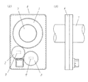
図1(a),(b)は被検回転軸7の多回転を検出する回転角度検出装置6の構成を示している。第1の歯車1は被検回転軸7に嵌合され、第2の歯車2は第1の歯車1と、第3の歯車3は第2の歯車2と順次係合されている。第2の歯車2および第3の歯車3の中央部には、それぞれ第1の磁石8および第2の磁石9が配置されている。
FIGS. 1A and 1B show the configuration of a rotation
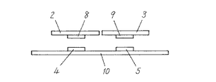
図2において、第1の磁石8に対向する位置には絶対回転角を検出する第1の絶対回転角検出部4が、第2の磁石9に対向する位置には絶対回転角を検出する第2の絶対回転角検出部5が配置されている。第1、第2の絶対回転角検出部4,5はそれぞれプリント基板10の上に配置されており、第1の絶対回転角検出部4は第2の歯車2の中央に固定された第1の磁石8の磁界方向を、また第2の絶対回転角検出部5は第3の歯車3の中央に固定された第2の磁石9の磁界方向を検出している。
In FIG. 2, a first absolute rotation
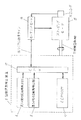
図3において、不揮発性メモリ(EEPROM)11は補正角などを記憶するためのものである。CPU12は不揮発性メモリ(EEPROM)11や第1、第2の絶対回転角検出部4,5と接続されており、絶対回転角を算出する。また、CPU12とモータコントローラ14とは角度信号や命令信号を送受信するシリアル通信ライン13で結ばれ、信号の送受信ができるようになっている。被検回転軸7にはモータ15が取り付けられており、モータコントローラ14によりその回転を高精度に駆動制御するようになっている。被検回転軸7の絶対回転角はエンコーダ16で高精度に検出してモータコントローラ14にこの絶対回転角を送信している。
In FIG. 3, a non-volatile memory (EEPROM) 11 is for storing correction angles and the like. The
次に、被検回転軸7の絶対回転角の検出方法について説明する。
Next, a method for detecting the absolute rotation angle of the
図1において被検回転軸7が回転すると、この被検回転軸7と嵌合している第1の歯車1が回転する。第1の歯車1が回転するとこれに連動して第1の歯車1と係合している第2の歯車2及び第2の歯車2に係合している第3の歯車3が回転する。第2の歯車2と第3の歯車3は歯数が異なるため、被検回転軸7に対して異なる速さで回転する。第1の絶対回転角検出部4からは第2の歯車2の絶対回転角を算出するための信号が、同様に第2の絶対回転角検出部5からは第3の歯車3の絶対回転角を算出するための信号が得られるようになっている。
In FIG. 1, when the
図4を用いて被検回転軸7の多回転での絶対回転角を算出する方法について説明する。図4の上段において、第1の歯車1の歯数をa、第2の歯車2の歯数をb、第3の歯車3の歯数をcとすると、第2の歯車2は被検回転軸7に嵌合している第1の歯車1の回転に対して歯数比(a/b)の速さで回転し、第3の歯車3は被検回転軸7に嵌合している第1の歯車1の回転に対して歯数比(a/c)の速さで回転するが、b≠cであるので第2の歯車2と第3の歯車3の絶対回転角の位相差はある規則性をもって変動する。図4の中段において被検回転軸7の多回転での絶対回転角19に対して、第2の歯車2の絶対回転角値17と第3の歯車3の絶対回転角値18の差が回転検出範囲において直線上に乗り、1対1に決定されることを示している。
A method for calculating the absolute rotation angle of the
次に、被検回転軸7の絶対回転角の検出精度を向上させる補正方法について説明する。
Next, a correction method for improving the detection accuracy of the absolute rotation angle of the
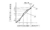
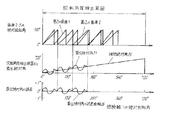
図4の下段において、被検回転軸7の多回転での絶対回転角19に対し、被検回転軸7の理想の絶対回転角(以下、理想絶対角という)20はここに示す直線上に乗るわけだが、第1の絶対回転角検出部4と第2の絶対回転角検出部5の信号より算出した絶対回転角(以下、算出絶対角という)21は、第1の歯車1、第2の歯車2の歯の配列精度や芯振れなどの機械的な検出誤差や第1の絶対回転角検出部4と第2の絶対回転角検出部5における電気的な検出誤差などが含まれており、被検回転軸7の理想絶対角20と一致しない。そこで被検回転軸7の絶対回転角19に対し、算出絶対角21と理想絶対角20との差を補正角として不揮発性メモリ(EEPROM)11に記憶し、算出絶対角21をこの補正角で補正することにより理想絶対角20に近づけて被検回転軸7の絶対回転角の検出精度を高めることができる。
In the lower part of FIG. 4, an ideal absolute rotation angle 20 (hereinafter referred to as an ideal absolute angle) 20 of the
図5〜図9と(表1)を用いて、被検回転軸7の絶対回転角の検出精度、特にリニアリティの補正方法について更に詳細に説明する。
With reference to FIGS. 5 to 9 and (Table 1), the detection accuracy of the absolute rotation angle of the
図5は横軸に回転角度検出装置6により算出された被検回転軸7の絶対回転角を、縦軸に被検回転軸7が実際に回転した絶対回転角を取っている。シリアル通信ライン13から送信されてくる算出絶対角が1°毎に変化するようにモータコントローラ14にてモータ15を制御する。その時の被検回転軸7の絶対回転角をエンコーダ16にて検出する。1°毎の算出絶対角に対する補正角は次式により求める。
In FIG. 5, the horizontal axis represents the absolute rotation angle of the
(1°毎の算出絶対角に対する補正角)=(被検回転軸7の絶対回転角)−(1°毎の算出絶対角)…(1)
1°より小さい算出絶対角(例えば0.1°毎の算出絶対角)に対する補正角は不揮発性メモリ(EEPROM)11に記憶していないので、1°毎の補正角より0.1°毎の算出絶対角を推定する。xを0.1°毎の算出絶対角、cをxよりも小さく最も近い1°毎の算出絶対角とする。すなわちc<x<c+1とする。mを(c+1)における補正角、nをcにおける補正角とし、これらの補正角に基づき被検回転軸7の算出絶対角を直線近似すると、算出絶対角Y1は次式で表される。
(Correction angle for calculated absolute angle every 1 °) = (Absolute rotational angle of
Since the correction angle for the calculated absolute angle smaller than 1 ° (for example, the calculated absolute angle every 0.1 °) is not stored in the nonvolatile memory (EEPROM) 11, the correction angle for every 0.1 ° is smaller than the correction angle for every 1 °. Estimate the calculated absolute angle. Let x be the calculated absolute angle every 0.1 °, and c be the closest calculated absolute angle every 1 ° smaller than x. That is, c <x <c + 1. When m is a correction angle in (c + 1), n is a correction angle in c, and the calculated absolute angle of the
Y1=(m−n+1)・(x−c)+n…(2)
理想的な算出絶対角とは被検回転軸7の実際の絶対回転角と一致しているものと定義できるので、理想的な算出絶対角をY2とすると
Y2=x−c…(3)
と表される。すなわちY1とY2との差が補正角となる。このことは(2)式、(3)式より次のように求められる。
Y1 = (m−n + 1) · (x−c) + n (2)
Since the ideal calculated absolute angle can be defined as being coincident with the actual absolute rotation angle of the
It is expressed. That is, the difference between Y1 and Y2 is the correction angle. This can be obtained as follows from equations (2) and (3).
Y1−Y2=(m−n)・(x−c)+n…(4)
(表1)ではこの(4)式を使って具体的に1°毎の補正角から0.1°毎の補正角を算出する方法を示している。初期設定時に回転角度検出装置6の算出絶対角が0°の時は被検回転軸7の絶対回転角も0°としている。まずモータコントローラ14によってモータ15を回転させ、シリアル通信ライン13を監視して算出絶対角が1°になった時に被検回転軸7の絶対回転角をエンコーダ16により確定する。この(表1)では0.8°となっている。すなわち回転角度検出装置6の算出絶対角1°に対する補正角は(1)式より−0.2°となる。これら1°毎の補正角から0°〜1°における0.1°毎の補正角を(4)式から求める。mは(c+1)すなわち算出絶対角1°における補正角なので−0.2°となる。一方、nはcにおける補正角すなわち0°における補正角なので0°となる。0°から1°までの0.1°毎の補正角を求める式はこれらの値を(4)式に代入して
Y1−Y2=(−0.2−0)・(x−0)+0
=−0.2・x…(5)
となる。例えば、算出絶対角xが0.1°の時の補正角は(5)式より−0.02°となる。これは算出絶対角が0.1°であっても被検回転軸7は0.08°(0.1−0.02)しか回転していないだろうと仮定している。また算出絶対角xが0.5°の時の補正角は(5)式より−0.1°となり、算出絶対角0.5°は0.4°(0.5−0.1)に修正される。
Y1-Y2 = (mn). (Xc) + n (4)
(Table 1) shows a method of calculating the correction angle every 0.1 ° from the correction angle every 1 ° using the equation (4). When the calculated absolute angle of the rotation
= −0.2 · x (5)
It becomes. For example, the correction angle when the calculated absolute angle x is 0.1 ° is −0.02 ° from the equation (5). This assumes that even if the calculated absolute angle is 0.1 °, the
引き続き、モータコントローラ14によって回転角度検出装置6の算出絶対角が2°となるまでモータ15を回転させる。この時の被検回転軸7の絶対回転角をエンコーダ16により検出する。(表1)では2.2°となっている。すなわち算出絶対角2°に対する補正角は(1)式より+0.2°となる。これら1°毎の補正角から1°〜2°における0.1°毎の補正角を(4)式から求めると次のようになる。
Subsequently, the
mは(c+1)すなわち回転角度検出装置6の算出絶対角2°における補正角なので+0.2°となる。一方、nはcにおける補正角すなわち1°における補正角なので−0.2°となる。1°から2°までの0.1°毎の補正角を求める式は、これらの値を(4)式に代入して
Y1−Y2=(0.2−(−0.2)・(x−1)−0.2
=0.4・(x−1)−0.2…(6)
となる。例えば、算出絶対角xが1.1°の時の補正角は(6)式より−0.16°となる。これは算出絶対角が1.1°であっても、被検回転軸7は0.94°(1.1−0.16)しか回転していないだろうと仮定している。また算出絶対角xが1.5°の時の補正角は(6)式より0°となり、算出絶対角1.5°は修正しなくても理想絶対角の直線上にあるだろうと推定している。
Since m is a correction angle at (c + 1), that is, the calculated
= 0.4 · (x−1) −0.2 (6)
It becomes. For example, the correction angle when the calculated absolute angle x is 1.1 ° is −0.16 ° from the equation (6). This assumes that even if the calculated absolute angle is 1.1 °, the
次に、モータコントローラ14によって回転角度検出装置6の算出絶対角が3°となるまでモータ15を回転させる。この時の被検回転軸7の絶対回転角を同様にエンコーダ16により検出する。(表1)では3.2°となっている。すなわち算出絶対角3°に対する補正角は(1)式より+0.2°となる。これら1°毎の補正角から2°〜3°における0.1°毎の補正角を(4)式から求めると次のようになる。
Next, the
mは(c+1)すなわち算出絶対角3°における補正角なので+0.2°となる。一方、nはcにおける補正角すなわち2°における補正角なので+0.2°となる。2°から3°までの0.1°毎の補正角を求める式は、これらの値を(4)式に代入して
Y1−Y2=(0.2−0.2)・(x−2)+0.2
=0.2…(7)
となる。例えば、算出絶対角xが2.1°の時の補正角は(7)式より0.2°となる。これは算出絶対角が2.1°であっても被検回転軸7は2.3°(2.1+0.2)回転しているだろうと推定している。また、算出絶対角xが2.5°の時の補正角も(7)式より0.2°となり、算出絶対角2.5°は2.7°(2.5+0.2)に修正する。
Since m is a correction angle at (c + 1), that is, a calculated absolute angle of 3 °, it is + 0.2 °. On the other hand, since n is a correction angle at c, that is, a correction angle at 2 °, it is + 0.2 °. The equation for obtaining the correction angle every 0.1 ° from 2 ° to 3 ° is obtained by substituting these values into the equation (4). Y1−Y2 = (0.2−0.2) · (x−2) ) +0.2
= 0.2 ... (7)
It becomes. For example, the correction angle when the calculated absolute angle x is 2.1 ° is 0.2 ° from the equation (7). This estimates that even if the calculated absolute angle is 2.1 °, the
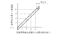
次に、図6にて被検回転軸7の絶対回転角の検出精度、特にヒステリシスの補正方法について説明する。
Next, the detection accuracy of the absolute rotation angle of the
図6は横軸に回転角度検出装置6により算出された絶対回転角を、縦軸に被検回転軸7の絶対回転角を取っている。シリアル通信ライン13から送信されてくる算出絶対角をモータコントローラ14にて監視しながらモータ15を回転させる。まず算出絶対角が増加する方向にモータ15を回転させる。次に逆方向にモータ15を回転させる。この時、算出絶対角が変動するまでの被検回転軸7の絶対回転角をエンコーダ16より求める。この値をヒステリシスの補正角として不揮発性メモリ(EEPROM)11に記憶する。このヒステリシスの要因としては歯車等のバックラッシュが考えられるので、この補正角は被検回転軸7の回転位置によって異なる。従って複数の回転位置でのヒステリシスの平均値を補正角としてもよい。
In FIG. 6, the horizontal axis represents the absolute rotation angle calculated by the rotation
回転角度検出装置6においては、算出絶対角が減少したら、このヒステリシスの補正角を算出絶対角に加えてヒステリシスによる精度の低下を補正する。次に、被検回転軸7が反転して算出絶対角が増加した場合は、ヒステリシスの補正は行わないようにする。
In the rotation
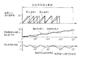
次に図7〜図9を用いて、算出絶対角に含まれる誤差を修正するリニアリティの補正角を記憶した不揮発性メモリ(EEPROM)11の容量をさらに削減する方法について説明する。 Next, a method for further reducing the capacity of the nonvolatile memory (EEPROM) 11 storing the linearity correction angle for correcting the error included in the calculated absolute angle will be described with reference to FIGS.
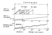
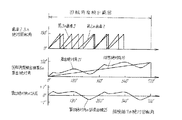
図7〜図9の下段に示すグラフでは、横軸に被検回転軸7の絶対回転角、縦軸に回転角度検出装置6の算出絶対角21の誤差をとっている。図7〜図9の中段に示すように算出絶対角21が理想絶対角20に一致した時に、下段に示した算出絶対角21の誤差がゼロとなり精度の高い回転角度検出装置が実現できていることを示している。図7では被検回転軸7の絶対回転角と算出絶対角21の誤差との間には相関がないので、検出範囲においてリニアリティの補正角を全て不揮発性メモリ(EEPROM)11に記憶し、算出絶対角21を理想絶対角20に近づける必要がある。そのため大容量の不揮発性メモリ(EEPROM)11が必要となる。一方、図8では算出絶対角の誤差曲線が被検回転軸7の絶対回転角360°の周期を持っている。これは算出絶対回転角の誤差が図1に示す第1の歯車1に起因するものが支配的であることを示している。この場合、図7の場合と異なり被検回転軸7の絶対回転角0〜360°の範囲におけるリニアリティの補正角だけを不揮発性メモリ(EEPROM)11に記憶することで、算出絶対角21を理想絶対角20に近づけることができる。ゆえに図7の場合より少ない不揮発性メモリ(EEPROM)11で算出絶対角の誤差を小さくすることができる。
In the graphs shown in the lower part of FIGS. 7 to 9, the horizontal axis represents the absolute rotation angle of the
一方、図9では算出絶対角の誤差曲線が第2の歯車2の回転周期を持っている。これは算出絶対角の誤差が図1に示す第2の歯車2に起因するものが支配的であることを示している。この場合、図7、図8の場合と異なり、第1の歯車1の歯数をa、第2の歯車2の歯数をb(ここでa>bとする)とすると、被検回転軸7の絶対回転角0〜360・b/a°の範囲におけるリニアリティの補正角だけを不揮発性メモリ(EEPROM)11に記憶することで算出絶対角を理想絶対角20に近づけることができる。ゆえに図8の場合より少ない不揮発性メモリ(EEPROM)11で算出絶対角の誤差を小さくすることができる。
On the other hand, in FIG. 9, the calculated absolute angle error curve has the rotation period of the
以上のように本実施の形態における回転角度検出装置6の回転角補正方法においては、検出範囲全域の第1の歯車1が1回転する範囲にわたって或いは第2の歯車2が1回転する範囲にわたって、被検回転軸7の算出絶対角に対する補正角を不揮発性メモリ(EEPROM)11に記憶するという方法により、歯車の機械的誤差や絶対回転角検出部の電気的誤差による絶対回転角の検出誤差も修正でき、被検回転軸の算出絶対角の精度向上を図ることができるという作用効果が得られる。また、補正角はある一定の絶対回転角おきに記憶しているため、より少ない容量の不揮発性メモリ11で被検回転軸7の検出精度を上げることができるという作用効果も得られる。
As described above, in the rotation angle correction method of the rotation
本発明にかかる回転角度検出装置の回転角補正方法は、より少ない容量の不揮発性メモリを用いた簡単な構成で、被検回転軸の多回転を高精度に検出することができるという作用効果を有しており、車両のパワーステアリング等で使用される回転角度検出装置の回転角補正方法として用いるのに適している。 The rotation angle correction method of the rotation angle detection device according to the present invention has the effect of being able to detect multiple rotations of the rotation axis to be detected with high accuracy with a simple configuration using a nonvolatile memory with a smaller capacity. It is suitable for use as a rotation angle correction method of a rotation angle detection device used for power steering of a vehicle.
1 第1の歯車
2 第2の歯車
3 第3の歯車
4 第1の絶対回転角検出部
5 第2の絶対回転角検出部
6 回転角度検出装置
7 被検回転軸
8 第1の磁石
9 第2の磁石
10 プリント基板
11 不揮発性メモリ(EEPROM)
12 CPU
13 シリアル通信ライン
14 モータコントローラ
15 モータ
16 エンコーダ
17 歯車2の絶対回転角値
18 歯車3の絶対回転角値
19 被検回転軸7の絶対回転角
20 被検回転軸7の理想絶対角の直線
21 被検回転軸7の算出絶対角
22 被検回転軸7の理想絶対角の直線
23 補正角より求めた被検回転軸7の算出絶対角の直線
24,25,26 算出絶対角の誤差曲線
DESCRIPTION OF
12 CPU
13
Claims (5)
Priority Applications (1)
| Application Number | Priority Date | Filing Date | Title |
|---|---|---|---|
| JP2004208150A JP2006029937A (en) | 2004-07-15 | 2004-07-15 | Compensation method for rotation angle of rotation angle detector |
Applications Claiming Priority (1)
| Application Number | Priority Date | Filing Date | Title |
|---|---|---|---|
| JP2004208150A JP2006029937A (en) | 2004-07-15 | 2004-07-15 | Compensation method for rotation angle of rotation angle detector |
Publications (1)
| Publication Number | Publication Date |
|---|---|
| JP2006029937A true JP2006029937A (en) | 2006-02-02 |
Family
ID=35896484
Family Applications (1)
| Application Number | Title | Priority Date | Filing Date |
|---|---|---|---|
| JP2004208150A Pending JP2006029937A (en) | 2004-07-15 | 2004-07-15 | Compensation method for rotation angle of rotation angle detector |
Country Status (1)
| Country | Link |
|---|---|
| JP (1) | JP2006029937A (en) |
Cited By (22)
| Publication number | Priority date | Publication date | Assignee | Title |
|---|---|---|---|---|
| JP2007232617A (en) * | 2006-03-02 | 2007-09-13 | Tokai Rika Co Ltd | Rotary angle detector and its initial setting method |
| KR100767185B1 (en) | 2006-07-26 | 2007-10-12 | 지멘스 오토모티브 주식회사 | Compensating installation for steering angle of car and method thereof |
| JP2009174863A (en) * | 2008-01-21 | 2009-08-06 | Seiko Epson Corp | Transducer |
| JP2010096708A (en) * | 2008-10-20 | 2010-04-30 | Denso Corp | Detector of motor rotational angle |
| JP2011149821A (en) * | 2010-01-21 | 2011-08-04 | Showa Corp | Rotation angle detection device and rotation angle detection method |
| US8204641B2 (en) | 2009-07-31 | 2012-06-19 | Denso Corporation | Traction motor control apparatus for vehicle |
| US8487563B2 (en) | 2009-11-27 | 2013-07-16 | Denso Corporation | Drive motor control apparatus for vehicle, motor control system, method for correcting rotation angle of motor, program for performing the same, rotation detecting apparatus |
| WO2014034317A1 (en) * | 2012-08-30 | 2014-03-06 | 富士フイルム株式会社 | Image pickup lens tube and method for controlling motion thereof |
| WO2014034315A1 (en) * | 2012-08-30 | 2014-03-06 | 富士フイルム株式会社 | Image pickup lens tube and method for controlling motion thereof |
| WO2014034316A1 (en) * | 2012-08-30 | 2014-03-06 | 富士フイルム株式会社 | Image pickup lens tube and method for controlling motion thereof |
| JP2015524053A (en) * | 2012-05-16 | 2015-08-20 | ファロ テクノロジーズ インコーポレーテッド | Apparatus and method for correcting bearing runout of laser tracker |
| US9423282B2 (en) | 2014-06-12 | 2016-08-23 | Faro Technologies, Inc. | Metrology device and a method for compensating for bearing runout error |
| CN105984490A (en) * | 2015-03-18 | 2016-10-05 | 现代摩比斯株式会社 | Zero point calibration apparatus and method for steering angle sensor using rotational displacement difference |
| US9482525B2 (en) | 2012-05-16 | 2016-11-01 | Faro Technologies, Inc. | Apparatus to compensate bearing runout in a three-dimensional coordinate measuring system |
| US9488476B2 (en) | 2014-02-06 | 2016-11-08 | Faro Technologies, Inc. | Apparatus and method to compensate bearing runout in an articulated arm coordinate measurement machine |
| US9542857B2 (en) | 2012-01-11 | 2017-01-10 | Pygmalion Kabushiki Kaisha | Math teaching tool |
| US9746304B2 (en) | 2012-05-16 | 2017-08-29 | Faro Technologies, Inc. | Apparatus and method to compensate bearing runout in an articulated arm coordinate measurement machine |
| WO2019059173A1 (en) | 2017-09-19 | 2019-03-28 | ミネベアミツミ株式会社 | Angle detection device, rotation amount specifying unit and rotation driving unit |
| JP2020109394A (en) * | 2019-01-04 | 2020-07-16 | 台達電子工業股▲ふん▼有限公司Delta Electronics,Inc. | Method and system for immediately correcting encoder |
| EP3851804A1 (en) | 2020-01-16 | 2021-07-21 | Jtekt Corporation | Rotation angle detection device |
| WO2021153613A1 (en) * | 2020-01-31 | 2021-08-05 | ミネベアミツミ株式会社 | Absolute encoder, program for outputting angle error information about absolute encoder, and method for outputting angle error information about absolute encoder |
| US11639192B2 (en) * | 2019-03-28 | 2023-05-02 | Denso Corporation | Detection unit |
-
2004
- 2004-07-15 JP JP2004208150A patent/JP2006029937A/en active Pending
Cited By (41)
| Publication number | Priority date | Publication date | Assignee | Title |
|---|---|---|---|---|
| JP2007232617A (en) * | 2006-03-02 | 2007-09-13 | Tokai Rika Co Ltd | Rotary angle detector and its initial setting method |
| JP4559982B2 (en) * | 2006-03-02 | 2010-10-13 | 株式会社東海理化電機製作所 | Rotation angle detection device and initial setting method thereof |
| KR100767185B1 (en) | 2006-07-26 | 2007-10-12 | 지멘스 오토모티브 주식회사 | Compensating installation for steering angle of car and method thereof |
| JP2009174863A (en) * | 2008-01-21 | 2009-08-06 | Seiko Epson Corp | Transducer |
| JP2010096708A (en) * | 2008-10-20 | 2010-04-30 | Denso Corp | Detector of motor rotational angle |
| US8204641B2 (en) | 2009-07-31 | 2012-06-19 | Denso Corporation | Traction motor control apparatus for vehicle |
| US8487563B2 (en) | 2009-11-27 | 2013-07-16 | Denso Corporation | Drive motor control apparatus for vehicle, motor control system, method for correcting rotation angle of motor, program for performing the same, rotation detecting apparatus |
| JP2011149821A (en) * | 2010-01-21 | 2011-08-04 | Showa Corp | Rotation angle detection device and rotation angle detection method |
| US9542857B2 (en) | 2012-01-11 | 2017-01-10 | Pygmalion Kabushiki Kaisha | Math teaching tool |
| JP2015524053A (en) * | 2012-05-16 | 2015-08-20 | ファロ テクノロジーズ インコーポレーテッド | Apparatus and method for correcting bearing runout of laser tracker |
| US10563969B2 (en) | 2012-05-16 | 2020-02-18 | Faro Technologies, Inc. | Apparatus and method to compensate bearing runout in an articulated arm coordinate measurement machine |
| US9746304B2 (en) | 2012-05-16 | 2017-08-29 | Faro Technologies, Inc. | Apparatus and method to compensate bearing runout in an articulated arm coordinate measurement machine |
| US9482525B2 (en) | 2012-05-16 | 2016-11-01 | Faro Technologies, Inc. | Apparatus to compensate bearing runout in a three-dimensional coordinate measuring system |
| WO2014034316A1 (en) * | 2012-08-30 | 2014-03-06 | 富士フイルム株式会社 | Image pickup lens tube and method for controlling motion thereof |
| US9372324B2 (en) | 2012-08-30 | 2016-06-21 | Fujifilm Corporation | Imaging lens barrel and method for controlling operation of the same |
| JP5736519B2 (en) * | 2012-08-30 | 2015-06-17 | 富士フイルム株式会社 | Imaging lens barrel and operation control method thereof |
| JP5736518B2 (en) * | 2012-08-30 | 2015-06-17 | 富士フイルム株式会社 | Imaging lens barrel and operation control method thereof |
| CN104704327A (en) * | 2012-08-30 | 2015-06-10 | 富士胶片株式会社 | Image pickup lens tube and method for controlling motion thereof |
| US9274305B2 (en) | 2012-08-30 | 2016-03-01 | Fujifilm Corporation | Imaging lens barrel and method for controlling operation of the same |
| CN104541133B (en) * | 2012-08-30 | 2016-03-16 | 富士胶片株式会社 | Imaging lens system lens barrel and method of controlling operation thereof |
| CN104541132B (en) * | 2012-08-30 | 2016-03-30 | 富士胶片株式会社 | Imaging lens system lens barrel and method of controlling operation thereof |
| US9307164B2 (en) | 2012-08-30 | 2016-04-05 | Fujifilm Corporation | Imaging lens barrel and method for controlling operation of the same |
| WO2014034315A1 (en) * | 2012-08-30 | 2014-03-06 | 富士フイルム株式会社 | Image pickup lens tube and method for controlling motion thereof |
| JPWO2014034316A1 (en) * | 2012-08-30 | 2016-08-08 | 富士フイルム株式会社 | Imaging lens barrel and operation control method thereof |
| JPWO2014034315A1 (en) * | 2012-08-30 | 2016-08-08 | 富士フイルム株式会社 | Imaging lens barrel and operation control method thereof |
| JPWO2014034317A1 (en) * | 2012-08-30 | 2016-08-08 | 富士フイルム株式会社 | Imaging lens barrel and operation control method thereof |
| JP5736520B2 (en) * | 2012-08-30 | 2015-06-17 | 富士フイルム株式会社 | Imaging lens barrel and operation control method thereof |
| WO2014034317A1 (en) * | 2012-08-30 | 2014-03-06 | 富士フイルム株式会社 | Image pickup lens tube and method for controlling motion thereof |
| CN104541132A (en) * | 2012-08-30 | 2015-04-22 | 富士胶片株式会社 | Image pickup lens tube and method for controlling motion thereof |
| CN104541133A (en) * | 2012-08-30 | 2015-04-22 | 富士胶片株式会社 | Image pickup lens tube and method for controlling motion thereof |
| US9488476B2 (en) | 2014-02-06 | 2016-11-08 | Faro Technologies, Inc. | Apparatus and method to compensate bearing runout in an articulated arm coordinate measurement machine |
| US9423282B2 (en) | 2014-06-12 | 2016-08-23 | Faro Technologies, Inc. | Metrology device and a method for compensating for bearing runout error |
| CN105984490A (en) * | 2015-03-18 | 2016-10-05 | 现代摩比斯株式会社 | Zero point calibration apparatus and method for steering angle sensor using rotational displacement difference |
| WO2019059173A1 (en) | 2017-09-19 | 2019-03-28 | ミネベアミツミ株式会社 | Angle detection device, rotation amount specifying unit and rotation driving unit |
| US11404938B2 (en) | 2017-09-19 | 2022-08-02 | Minebea Mitsumi Inc. | Angle detection apparatus, rotation amount specification unit, and rotary driving unit |
| JP2020109394A (en) * | 2019-01-04 | 2020-07-16 | 台達電子工業股▲ふん▼有限公司Delta Electronics,Inc. | Method and system for immediately correcting encoder |
| US11639192B2 (en) * | 2019-03-28 | 2023-05-02 | Denso Corporation | Detection unit |
| EP3851804A1 (en) | 2020-01-16 | 2021-07-21 | Jtekt Corporation | Rotation angle detection device |
| US11953396B2 (en) | 2020-01-16 | 2024-04-09 | Jtekt Corporation | Rotation angle detection device |
| WO2021153613A1 (en) * | 2020-01-31 | 2021-08-05 | ミネベアミツミ株式会社 | Absolute encoder, program for outputting angle error information about absolute encoder, and method for outputting angle error information about absolute encoder |
| JP7441061B2 (en) | 2020-01-31 | 2024-02-29 | ミネベアミツミ株式会社 | Absolute encoder, absolute encoder angular error information output program, absolute encoder angular error information output method |
Similar Documents
| Publication | Publication Date | Title |
|---|---|---|
| JP2006029937A (en) | Compensation method for rotation angle of rotation angle detector | |
| US7583080B2 (en) | Rotation angle detection device and rotation angle correction method | |
| JP4474872B2 (en) | Absolute rotation angle and torque detector | |
| CN100552374C (en) | Rotation angle detection apparatus and anglec of rotation modification method | |
| TWI471531B (en) | Encoder system, signal processing method | |
| US10011298B2 (en) | Electric power assisted steering system | |
| US10442460B2 (en) | Electric power assisted steering system | |
| US10155532B2 (en) | Electric power assisted steering system | |
| JP2006220529A (en) | Detection device for absolute angle of rotation and torque | |
| CN103234504B (en) | A kind of error calibration, compensation method and its computer program, computer-readable recording medium | |
| US10005491B2 (en) | Electric power assisted steering system | |
| KR20190035910A (en) | A sensor system for determining an absolute rotational angle of a shaft, a method for determining an absolute rotational angle of a shaft, and a vehicle having a sensor system | |
| JP2022043321A (en) | Calibration value generation method of encoder, calibration value generation system of encoder, and encoder | |
| JP5402313B2 (en) | Encoder and signal processing method | |
| CN110617760B (en) | Initial setting method and initial setting device for rotation angle detection device | |
| CN117168530B (en) | Self-calibration method of magnetic encoder, magnetic encoder and motor | |
| US20150316371A1 (en) | Method for determining the absolute position of a linear actuator | |
| JP5096399B2 (en) | Rotation angle detector | |
| JP2005016968A (en) | Turning angle detector | |
| JP6452232B2 (en) | Magnet analyzer | |
| JP2013120090A (en) | Rotation angle detector | |
| KR100827818B1 (en) | Method for measuring the angles of rotatable bodies | |
| JP5706355B2 (en) | Rotation angle detector | |
| KR20100076298A (en) | Apparatus and method for detecting angle | |
| JP2007278924A (en) | Turning angle detector |