JP2006010352A - Sensor chip and its manufacturing method - Google Patents
Sensor chip and its manufacturing method Download PDFInfo
- Publication number
- JP2006010352A JP2006010352A JP2004184187A JP2004184187A JP2006010352A JP 2006010352 A JP2006010352 A JP 2006010352A JP 2004184187 A JP2004184187 A JP 2004184187A JP 2004184187 A JP2004184187 A JP 2004184187A JP 2006010352 A JP2006010352 A JP 2006010352A
- Authority
- JP
- Japan
- Prior art keywords
- substrate
- sensor chip
- cover layer
- spacer layer
- substrate sheet
- Prior art date
- Legal status (The legal status is an assumption and is not a legal conclusion. Google has not performed a legal analysis and makes no representation as to the accuracy of the status listed.)
- Pending
Links
Images


Landscapes
- Investigating Or Analysing Biological Materials (AREA)
Abstract
Description
本発明は、試料に含まれる化学物質を、簡易に定量、検出することができるセンサチップ、特にバイオセンサチップに関する。本発明は、さらにこのセンサチップの製造方法に関するものである。 The present invention relates to a sensor chip, particularly a biosensor chip, that can easily quantitate and detect a chemical substance contained in a sample. The present invention further relates to a method for manufacturing this sensor chip.
バイオセンサチップは、微量試料をチップ内の反応部に導入し、該チップ内で、該微量試料について酵素反応や抗原−抗体反応等の生化学反応を起こし、該生化学反応により得られる情報をチップ外へ出力するセンサチップである。このバイオセンサチップは、生体の持つ優れた分子識別機能を利用するものであり、微量の化学物質の迅速かつ簡便な測定を可能にするものとして注目されており、例えば、血液中のグルコース量(血糖値)や尿糖値を測定する血糖値センサ、尿糖値センサとして、糖尿病を自己管理し予防する家庭内健康診断(セルフケア)等に使用されている。 The biosensor chip introduces a trace amount sample into a reaction part in the chip, causes a biochemical reaction such as an enzyme reaction or an antigen-antibody reaction in the trace amount sample in the chip, and obtains information obtained by the biochemical reaction. This is a sensor chip that outputs to the outside of the chip. This biosensor chip utilizes an excellent molecular identification function of a living body, and has been attracting attention as being capable of quick and simple measurement of a small amount of chemical substance. For example, the amount of glucose in blood ( As blood glucose level sensors and urine sugar level sensors for measuring blood sugar levels) and urine sugar levels, they are used for home health diagnosis (self-care) for self-management and prevention of diabetes.
特開平10−2874号公報や特開平11−94790号公報には、このようなバイオセンサチップの一例が記載されている。これらのバイオセンサチップは、基板の上に、スペーサ層が積層され、さらにその上にカバー層が積層されてなるものであり、このスペーサ層により、基板とカバー層間に中空の反応部が形成され、この反応部に試料が導入されて生化学反応等が行われる。 An example of such a biosensor chip is described in JP-A-10-2874 and JP-A-11-94790. These biosensor chips are formed by laminating a spacer layer on a substrate and further laminating a cover layer thereon, and this spacer layer forms a hollow reaction part between the substrate and the cover layer. Then, a sample is introduced into the reaction part to perform a biochemical reaction or the like.
これらの積層型バイオセンサチップにおいては、基板やカバー層とスペーサ層との貼り合せ、スペーサ層を構成するスペーサ材(スペーサ層を構成する1層のフィルム)同士の貼り合せには、主に、粘着材が塗布された両面テープで貼り合せる方法や、スペーサ材の表面に粘着材をスクリーン印刷等で塗布して貼り合せる方法が用いられている(特開平11−94790号公報)。粘着材は、圧着するだけで固着することができ、加熱やUV照射等の処理が不要であるので、生産性の点ですぐれている。又バイオセンサチップに使用される酵素等は熱やUVに弱い場合があるので、そのような場合には、固着手段としてできるかぎり粘着材の使用が望まれる。しかし、この粘着材は、粘着性を高めるためにある程度柔らかく、変形しやすい素材を使用せざるを得ないので、積層時に印加された残留応力による経時変化や、環境温度、湿度等の変化に伴い、寸法の変化を生じやすく、粘着材層の厚み等も変化しやすい。 In these laminated biosensor chips, the bonding between the substrate and the cover layer and the spacer layer, the bonding between the spacer materials constituting the spacer layer (one layer film constituting the spacer layer), A method of bonding with a double-sided tape coated with an adhesive material or a method of applying an adhesive material on the surface of a spacer material by screen printing or the like is used (Japanese Patent Laid-Open No. 11-94790). The pressure-sensitive adhesive material can be fixed simply by pressure bonding, and does not require treatment such as heating or UV irradiation, and is excellent in productivity. In addition, since enzymes and the like used in biosensor chips may be weak against heat and UV, in such cases, it is desirable to use an adhesive material as much as possible as a fixing means. However, this adhesive material must be made of a material that is soft to some extent and easily deformed in order to increase the adhesiveness, so that it changes with time due to residual stress applied during lamination, changes in environmental temperature, humidity, etc. , Dimensional changes are likely to occur, and the thickness of the adhesive layer is likely to change.
粘着材による貼り合せ後、粘着材層の厚みが変化すると、基板とカバー層間の距離も変化し、その結果中空の反応部の体積も変化する。中空の反応部の体積が変化すると、反応部に導入される試料の量が変動し、その結果測定値が変動するとの問題が生じる。 When the thickness of the adhesive material layer changes after bonding with the adhesive material, the distance between the substrate and the cover layer also changes, and as a result, the volume of the hollow reaction part also changes. When the volume of the hollow reaction part changes, the amount of the sample introduced into the reaction part fluctuates, resulting in a problem that the measured value fluctuates.
一方、特開平11−94791号公報には、スペーサ層を介さず、基板とカバー層を直接接着させてなるバイオセンサチップが記載されている。このバイオセンサチップは、
基板に立ち上げ部を有し、この立ち上げ部がカバー層と接着している。しかしこのバイオセンサチップは、スペーサ層を使用せず、前記立ち上げ部とカバー層間の狭い接着部のみで基板とカバー層を固定しているため、強度的に弱く、信頼性の点で問題がある。又、カバー層の前記接着部以外の表面全体が中空反応部の一面となるので、スペーサ層を使用した場合と比べて、反応部の体積が大きくなり、必要とする試料の量が増大するとの問題もある。
On the other hand, Japanese Patent Application Laid-Open No. 11-94791 discloses a biosensor chip in which a substrate and a cover layer are directly bonded without using a spacer layer. This biosensor chip
The substrate has a raised portion, and this raised portion is bonded to the cover layer. However, this biosensor chip does not use a spacer layer, and the substrate and the cover layer are fixed only by a narrow adhesive portion between the rising portion and the cover layer. Therefore, the biosensor chip is weak in strength and has a problem in reliability. is there. In addition, since the entire surface of the cover layer other than the adhesive portion is one surface of the hollow reaction portion, the volume of the reaction portion becomes larger than that in the case where the spacer layer is used, and the amount of sample required increases. There is also a problem.
そこで、スペーサ層を使用したバイオセンサチップ、すなわち基板、カバー層、及び基板とカバー層間に挟装されるスペーサ層を有するバイオセンサチップであって、基板、カバー層及びスペーサ層等の間の貼り合せに粘着材を用いた場合であっても、経時変化や、環境温度、湿度等の変化に伴う反応部の体積変化を生じないバイオセンサチップの開発が望まれていた。
本発明は、基板、カバー層、及び基板とカバー層間に挟装されるスペーサ層を有するセンサチップであって、各層の貼り合せ等に粘着材を用いた場合であっても、経時変化や、環境温度、湿度等の変化に伴う反応部の体積変化を生じないセンサチップを提供することを課題とする。 The present invention is a sensor chip having a substrate, a cover layer, and a spacer layer sandwiched between the substrate and the cover layer, even when an adhesive material is used for bonding each layer, etc. It is an object of the present invention to provide a sensor chip that does not cause a change in the volume of a reaction part accompanying changes in environmental temperature, humidity, and the like.
本発明者は、鋭意検討の結果、基板とカバー層を、それらの1端において互いに強力に結合しその間隔が変動しないように固定することにより、前記の課題が達成されることを見出し、本発明を完成した。 As a result of intensive studies, the inventor has found that the above-described problem can be achieved by firmly bonding the substrate and the cover layer to each other at one end thereof and fixing the distance so as not to fluctuate. Completed the invention.
本発明は、基板、カバー層、及び基板とカバー層間に挟装されるスペーサ層を有し、さらに基板とカバー層間に中空反応部及びこの中空反応部内に検知手段を有するセンサチップであって、前記基板及びカバー層が、それらの1端において互いに結合し一体化されていることを特徴とするセンサチップを提供するものである(請求項1)。 The present invention is a sensor chip having a substrate, a cover layer, and a spacer layer sandwiched between the substrate and the cover layer, and further having a hollow reaction portion between the substrate and the cover layer and a detection means in the hollow reaction portion, The substrate and the cover layer are combined with each other at one end thereof to provide a sensor chip (Claim 1).
基板及びカバー層には、両者を強力に結合できる限りは異なる材質を用いてもよいが、又両者間の強力な結合を容易に達成するためには同じ材質を用いることが好ましい。これらの材質としては、絶縁性材料のフィルムが選ばれ、絶縁性材料としては、セラミックス、ガラス、紙、生分解性材料(例えば、ポリ乳酸微生物生産ポリエステル等)、ポリ塩化ビニル、ポリプロピレン、ポリスチレン、ポリカーボネート、アクリル樹脂、ポリブチレンテレフタレート、ポリエチレンテレフタレート(PET)等の熱可塑性樹脂、エポキシ樹脂等の熱硬化樹脂、UV硬化樹脂等のプラスチック材料を例示することができる。機械的強度、柔軟性、及びチップの作製や加工の容易さ、特に下記の二つ折り加工の容易さ等から、PET等のプラスチック材料が好ましい。 Different materials may be used for the substrate and the cover layer as long as they can be strongly bonded, but the same material is preferably used in order to easily achieve strong bonding between the two. As these materials, films of insulating materials are selected, and as insulating materials, ceramics, glass, paper, biodegradable materials (for example, polylactic acid microbial production polyester, etc.), polyvinyl chloride, polypropylene, polystyrene, Examples thereof include thermoplastic materials such as polycarbonate, acrylic resin, polybutylene terephthalate and polyethylene terephthalate (PET), thermosetting resins such as epoxy resins, and plastic materials such as UV curable resins. A plastic material such as PET is preferable from the viewpoint of mechanical strength, flexibility, and ease of chip fabrication and processing, particularly ease of bi-folding described below.
基板及びカバー層の厚みは、互いに同じであっても、異なっていてもよい。これらの厚みの好ましい範囲は、センサチップの用途等により変動し、特に限定されないが、血糖値センサ等バイオセンサチップの場合は、100〜300μm程度が好ましい。 The thickness of the substrate and the cover layer may be the same as or different from each other. The preferred range of these thicknesses varies depending on the application of the sensor chip and is not particularly limited. However, in the case of a biosensor chip such as a blood glucose level sensor, about 100 to 300 μm is preferable.
本発明のセンサチップは、又、基板とカバー層間に挟装されるスペーサ層を有する。挟装されるとは、スペーサ層の一方の側が基板と貼り合わされており、他方の側がカバー層と貼り合わされていることを意味する。スペーサ層と、基板又はカバー層間に、電極等の他の層があってもよい。貼り合わせには、両面テープ等の粘着材が用いられるが、本発明においては、粘着材を用いた場合であっても、経時等によるチップの厚みの変動が抑制される。 The sensor chip of the present invention also has a spacer layer sandwiched between the substrate and the cover layer. To be sandwiched means that one side of the spacer layer is bonded to the substrate, and the other side is bonded to the cover layer. There may be other layers such as electrodes between the spacer layer and the substrate or cover layer. For the bonding, an adhesive material such as a double-sided tape is used. In the present invention, even when an adhesive material is used, fluctuations in the thickness of the chip over time and the like are suppressed.
スペーサ層は、単層のスペーサ材からなるものでもよいが、複数層のスペーサ材の積層体でもよい。複数層のスペーサ材中の、各スペーサ材がそれぞれ異なるものであってもよい。スペーサ層の材質としては、前記の基板やカバー層に用いられる材料として例示されたものと同様なものを例示することができる。例えば、これらの材質や粘着材をスクリーン印刷等の手法で基板上や他のスペーサ材上に塗布し、その後最上層のスペーサ材とカバー層を貼り合せることにより、基板とカバー層間に挟装されたスペーサ層を形成することができる。このように、複数層のスペーサ材からなる場合、スペーサ材間の貼り合わせには、粘着材を用いることができるが、前記と同様、粘着材を用いた場合であっても、本発明においては、経時等によるチップの厚みの変動が抑制される。 The spacer layer may be made of a single-layer spacer material, but may be a laminate of a plurality of spacer materials. Each spacer material in a plurality of layers of spacer materials may be different. Examples of the material of the spacer layer can include the same materials as those exemplified as the materials used for the substrate and the cover layer. For example, these materials and adhesive materials are applied on the substrate or other spacer material by a method such as screen printing, and then the uppermost spacer material and the cover layer are bonded together, so that they are sandwiched between the substrate and the cover layer. A spacer layer can be formed. As described above, when the spacer material is composed of a plurality of layers, an adhesive material can be used for bonding between the spacer materials. Further, variation in the thickness of the chip due to aging or the like is suppressed.
本発明のセンサチップは、さらに基板とカバー層間に中空反応部を有する。中空反応部は、センサチップの使用時に試料を導入し、導入された試料が化学反応する部分である。この中空反応部は、スペーサ層が有する溝により形成することができ、下記のようにその中に電極が含まれ、又バイオセンサチップ等の場合は、触媒、酵素等の生化学反応をさせるための薬剤がその中に固定されており、これらにより、試料の化学反応が促進される。 The sensor chip of the present invention further has a hollow reaction part between the substrate and the cover layer. The hollow reaction part is a part where a sample is introduced when the sensor chip is used, and the introduced sample chemically reacts. This hollow reaction part can be formed by a groove of the spacer layer, and includes an electrode therein as described below, and in the case of a biosensor chip or the like, in order to cause a biochemical reaction such as a catalyst or an enzyme. The drug is immobilized therein, and these promote the chemical reaction of the sample.
例えば、血液中のグルコース量を測定するグルコースバイオセンサチップの場合は、この部分に、グルコースオキシダーゼ(GOD)層や、グルコースオキシダーゼ−電子受容体(メディエータ)混合物層、グルコースオキシダーゼ−アルブミン混合物層、又はグルコースオキシダーゼ−電子受容体−アルブミン混合物層等が形成される。グルコースオキシダーゼ以外の酵素、例えばグルコースデヒドロゲナーゼ(GDH)等を用い、これらの層が形成される場合もある。又、添加剤として緩衝剤や親水性高分子等を薬剤中に含めてもよい。 For example, in the case of a glucose biosensor chip that measures the amount of glucose in the blood, a glucose oxidase (GOD) layer, a glucose oxidase-electron acceptor (mediator) mixture layer, a glucose oxidase-albumin mixture layer, or A glucose oxidase-electron acceptor-albumin mixture layer or the like is formed. These layers may be formed using enzymes other than glucose oxidase, such as glucose dehydrogenase (GDH). Moreover, you may include a buffering agent, hydrophilic polymer, etc. in a chemical | medical agent as an additive.
測定対象である試料、例えば血液、尿や、生産ライン上で抜き取られた水溶液試料等は、試料導入口より前記中空反応部に導入される。試料導入口は、基板やカバー層に設けられ、試料導入路を通して前記中空反応部と連結されていてもよいし、前記中空反応部が、スペーサ層の少なくとも1方の辺で開口し、試料導入口を形成してもよい。試料導入口は複数設けられていてもよい。 A sample to be measured, for example, blood, urine, an aqueous solution sample extracted on the production line, and the like are introduced into the hollow reaction part from a sample introduction port. The sample introduction port is provided in the substrate or the cover layer, and may be connected to the hollow reaction part through the sample introduction path, or the hollow reaction part opens at at least one side of the spacer layer, and the sample introduction A mouth may be formed. A plurality of sample inlets may be provided.
本発明のセンサチップは、さらに中空反応部内に、検知手段を有する、すなわち反応部内に露出している。ここで、検知手段とは、少なくとも2以上の電極からなる。これらの電極は通常、作用極、対極といわれているが、検知手段は、さらに参照極等の他の電極やその他の手段を有してもよい。電極は、中空反応部に所定の電圧を印加する、中空反応部からの電流値を測定する等の作用を奏するものであり、この電極からの信号に基づき試料中の化学物質の検出や定量が行われる。 The sensor chip of the present invention further has detection means in the hollow reaction part, that is, is exposed in the reaction part. Here, the detection means is composed of at least two electrodes. These electrodes are generally referred to as a working electrode and a counter electrode, but the detection means may further include other electrodes such as a reference electrode and other means. The electrode exerts an action such as applying a predetermined voltage to the hollow reaction part and measuring a current value from the hollow reaction part, and detection and quantification of chemical substances in the sample can be performed based on a signal from the electrode. Done.
前記電極は、中空反応部内で露出しているが、さらに基板、スペーサ層若しくはカバー層内、又はこれらの間に前記電極のリード線部分が形成され、センサチップ外部と電気的に導通可能になっており、このリード線部分を通して所定の電圧の印加や、電流値の測定等が行われる。 The electrode is exposed in the hollow reaction portion, but further, a lead wire portion of the electrode is formed in the substrate, the spacer layer or the cover layer, or between them, and can be electrically connected to the outside of the sensor chip. A predetermined voltage is applied and a current value is measured through the lead wire portion.
本発明のセンサチップは、基板及びカバー層が、それらの1端において互いに結合し一体化されていることを特徴とする。結合し一体化されているとは、両者間の位置関係が変動しないように結合されていることを意味する。従って、基板とカバー層の間隔は、この部分で固定され変動しない。この結果、中空反応部における基板とカバー層の間隔の変動も抑制され、従来技術で問題であった、経時変化や、環境温度、湿度等の変化に伴う反応部の体積変化も抑制される。 The sensor chip of the present invention is characterized in that the substrate and the cover layer are bonded and integrated with each other at one end thereof. Combined and integrated means that they are combined so that the positional relationship between them does not change. Accordingly, the distance between the substrate and the cover layer is fixed at this portion and does not vary. As a result, fluctuations in the distance between the substrate and the cover layer in the hollow reaction part are also suppressed, and changes in the volume of the reaction part accompanying changes with time and changes in environmental temperature, humidity, etc., which are problems in the prior art, are also suppressed.
通常のセンサチップでは、中空反応部は、センサチップの中央より、一方の端に近い位置に設けられる。そこで、前記1端として、この中空反応部に近い方の端を選び、この端で基板及びカバー層を強力に結合し一体化すると、中空反応部の体積変化をより有効に抑制することができ好ましい。 In a normal sensor chip, the hollow reaction part is provided at a position closer to one end than the center of the sensor chip. Therefore, if the end closer to the hollow reaction part is selected as the one end, and the substrate and the cover layer are strongly bonded and integrated at this end, the volume change of the hollow reaction part can be more effectively suppressed. preferable.
一端において互いに結合し一体化されている基板及びカバー層を得る方法は特に限定されない。例えば、基板及びカバー層が熱可塑性樹脂で形成されている場合は、両者をこの部分で溶融接着する方法も挙げられるし、又両者を強力な接着剤で接着する方法も挙げられる。 A method for obtaining a substrate and a cover layer which are bonded and integrated with each other at one end is not particularly limited. For example, in the case where the substrate and the cover layer are formed of a thermoplastic resin, a method of melt-bonding them together at this portion can be mentioned, and a method of bonding them together with a strong adhesive can also be mentioned.
中でも、1枚の基板シートを略2等分する折り曲げ線を中心とし、その基板シートを2つ折りし、その折り曲げ線の一方を基板とし、他方をカバー層とする方法が、センサチップの製造が容易であり、かつ安定して強力な結合が得られるので好ましい方法として挙げられる。請求項2は、この好ましい方法により得られるセンサチップに該当し、前記のセンサチップであって、基板及びカバー層が、1枚の基板シートを略2等分する折り曲げ線を中心とし、その基板シートを2つ折りして形成されることを特徴とするセンサチップを提供するものである。
In particular, a method of manufacturing a sensor chip is a method in which one substrate sheet is centered on a fold line that bisects the substrate sheet, the substrate sheet is folded in half, one of the fold lines is a substrate, and the other is a cover layer. It is easy and can be mentioned as a preferred method because a stable and strong bond can be obtained.
折り曲げ線を中心として2つ折りする方法には、この折り曲げ線の位置で2つ折りする方法とともに、折り曲げ線に平行でかつ折り曲げ線から等距離にある2本の直線の位置で、断面がコの字型になるように、折り曲げる方法も含まれる。 In the method of folding in two around the fold line, in addition to the method of folding in two at the position of the fold line, the cross section is U-shaped at the position of two straight lines that are parallel to the fold line and equidistant from the fold line. Also included is a method of bending to form a mold.
本発明のセンサチップは、特にバイオセンサチップとして、血液中のグルコース量(血糖値)や尿糖値を測定する血糖値センサ、尿糖値センサ等として好適に用いられる。請求項3は、この好ましい態様に該当し、前記のセンサチップであって、バイオセンサチップであることを特徴とするセンサチップを提供するものである。 The sensor chip of the present invention is particularly suitably used as a biosensor chip as a blood glucose level sensor, a urine glucose level sensor, or the like that measures the amount of glucose (blood glucose level) or urine sugar level in blood. A third aspect of the present invention corresponds to this preferred embodiment, and provides a sensor chip that is the above-described sensor chip and is a biosensor chip.
前記の基板及びカバー層が、1枚の基板シートを略2等分する折り曲げ線を中心とし、その基板シートを2つ折りして形成されることを特徴とするセンサチップは、好ましくは次に述べる構成からなる方法により製造される。本発明は、これらの好ましい態様に該当するセンサチップの製造方法も提供するものである。 The sensor chip, wherein the substrate and the cover layer are formed by folding the substrate sheet in two, with a fold line that divides one substrate sheet into approximately two equal parts as a center. Manufactured by a method consisting of components. The present invention also provides a method of manufacturing a sensor chip corresponding to these preferred embodiments.
すなわち本発明の請求項4は、基板、カバー層、及び基板とカバー層間に挟装されるスペーサ層を有し、さらに基板とカバー層間に中空反応部及びこの中空反応部内に検知手段を有するセンサチップの製造方法であって、1枚の基板シート上の、この基板シートを略2等分する折り曲げ線の少なくとも一方の側に、検知手段を形成し、前記折り曲げ線を中心として前記基板シートを2つ折りし、その後2つ折りされた基板シートの間に溝部を有するスペーサ層を挿入し、このスペーサ層と前記2つ折りされた基板シートとを貼り合せて積層体を得ることを特徴とするセンサチップの製造方法を提供する。
That is,
又、本発明の請求項5は、基板、カバー層、及び基板とカバー層間に挟装されるスペーサ層を有し、さらに基板とカバー層間に中空反応部及びこの中空反応部内に検知手段を有するセンサチップの製造方法であって、1枚の基板シート上の、この基板シートを略2等分する折り曲げ線の少なくとも一方の側に、検知手段の形成及び溝部を有するスペーサ層の形成を行った後、前記折り曲げ線を中心として前記基板シートを2つ折りし、前記スペーサ層と前記基板シートの他方の側とを貼り合せて積層体を得ることを特徴とするセンサチップの製造方法を提供する。 According to a fifth aspect of the present invention, there is provided a substrate, a cover layer, and a spacer layer sandwiched between the substrate and the cover layer, and further, a hollow reaction portion between the substrate and the cover layer, and a detection means in the hollow reaction portion. A method of manufacturing a sensor chip, in which a detection means and a spacer layer having a groove are formed on at least one side of a fold line that divides the substrate sheet into two substantially equal parts. Thereafter, the substrate sheet is folded in two with the fold line as a center, and the spacer layer and the other side of the substrate sheet are bonded together to obtain a laminated body.
請求項4の方法は、検知手段が形成された1枚の基板シートを、略2等分するように2つ折りして一体基板を作製し、2つ折りされた基板間に、中空反応部を有するスペーサ層を挿入して貼り合せる方法であり、請求項5の方法は、検知手段が形成された1枚の基板シートを略2等分する線の一方の側に、中空反応部を有するスペーサ層を形成した後、この線に沿って2つ折りして、スペーサ層と基板を貼り合せる方法である。
According to the method of
このように、スペーサ層の形成は、2つ折り前の積層でもよく、2つ折り後の挿入でもよい。2つ折り後にスペーサ層を挿入する場合は、挿入前に、基板やカバー層及び/又はスペーサ層の貼り合せ部分に粘着材があると挿入が困難となる。そこで、粘着材の代りに、熱硬化あるいはUV硬化型接着剤等を用い、挿入後に加熱あるいはUV照射して、スペーサ層と、基板、カバー層とを貼り合せ、固定することが望ましい。 As described above, the spacer layer may be formed by lamination before folding or by insertion after folding. In the case where the spacer layer is inserted after being folded in two, it becomes difficult to insert the adhesive layer in the bonded portion of the substrate, the cover layer, and / or the spacer layer before the insertion. Therefore, it is desirable to use a thermosetting or UV curable adhesive or the like instead of the adhesive material, and heat or UV-irradiate after insertion to bond and fix the spacer layer, the substrate and the cover layer.
スペーサ層を、基板シートの2つ折り前に積層する方法、及び2つ折り後に挿入する方法のいずれの場合でも、基板シートとして熱可塑性樹脂からなるものを用い、2つ折り後、2つ折り部分を熱処理することが好ましい。この熱処理により、折り曲げによる残留応力が解消しこの部分が固定化するので、基板とカバー層との位置関係の経時等による変動を抑制する効果が増す。請求項6は、この好ましい態様に該当し、前記の製造方法であって、基板シートが、熱可塑性樹脂から形成され、基板シートの2つ折り後、2つ折り部分を熱処理することを特徴とするセンサチップの製造方法を提供するものである。 In any case of the method of laminating the spacer layer before the substrate sheet is folded in half and the method of inserting the substrate sheet after being folded in two, the substrate sheet is made of a thermoplastic resin, and the folded portion is heat-treated after being folded in two. It is preferable. By this heat treatment, the residual stress due to the bending is eliminated and this portion is fixed, so that the effect of suppressing the variation of the positional relationship between the substrate and the cover layer over time is increased. Claim 6 corresponds to this preferred embodiment, and is the manufacturing method described above, wherein the substrate sheet is formed of a thermoplastic resin, and the folded portion is heat-treated after being folded in half. A method for manufacturing a chip is provided.
前記のように、2つ折りには、断面がコの字型になるように、折り曲げる方法も含まれる。2つ折り及びその後の熱処理については、基板シートとしてPET等の熱可塑性樹脂を用いた場合は、熱可塑性樹脂からなるシートをプレス成形のように熱を印加しつつ折り曲げてコの字状に成形する方法が、精度良く経済的に製造できるので特に好ましい。この時、あらかじめシートの折り曲げ線に沿って部分的に孔を空けたり(いわゆるミシン目)、溝を形成したり(いわゆるハーフカット)する処理を行なった後、折り曲げを行えば、折り曲げ精度は更に改善される。なお、基板とカバー層の固定強度を高く保つためには、孔を空ける方法よりも、溝で処理をする方法が望ましい。 As described above, the half-folding includes a method of bending so that the cross section becomes a U-shape. Regarding the folding in half and the subsequent heat treatment, when a thermoplastic resin such as PET is used as the substrate sheet, the sheet made of the thermoplastic resin is bent while applying heat as in press molding to form a U-shape. The method is particularly preferred because it can be produced accurately and economically. At this time, if the sheet is folded in advance (so-called perforation) or grooves are formed (so-called half cut) along the folding line of the sheet in advance, the folding accuracy is further improved. Improved. In order to keep the fixing strength between the substrate and the cover layer high, a method of treating with grooves is preferable to a method of making holes.
バイオセンサチップの場合は、酵素等からなる薬剤が、中空反応部内の基板上やカバー層上に固定される。スペーサ層を、基板シートの2つ折り前に基板シートに積層する方法においては、このような薬剤の固定は、2つ折り前、2つ折り後のいずれにおいても行うことができる。 In the case of a biosensor chip, a drug composed of an enzyme or the like is fixed on the substrate or the cover layer in the hollow reaction part. In the method of laminating the spacer layer on the substrate sheet before the substrate sheet is folded in half, such fixation of the drug can be performed either before or after the folding.
但し、2つ折り後の固定は、ディスペンサ等による滴下による塗布が困難な場合が多いので、生産性の観点からは、2つ折り前に基板シート上に固定する方法が好ましい。一方、2つ折り前の固定では、前記の2つ折り部分の熱処理を行う場合は、酵素等の薬剤が熱により劣化する可能性がある。そこで、酵素等の薬剤が熱に弱い場合は、この薬剤固定部分が加熱領域から外れるようする、等の処置が必要である。なお、薬剤の固定位置の位置決めを容易にするためには、スペーサ層の積層前よりもスペーサ層の積層後に薬剤の固定を行う方法が好ましい。 However, since fixing after folding is often difficult to apply by dropping with a dispenser or the like, a method of fixing on the substrate sheet before folding is preferable from the viewpoint of productivity. On the other hand, in the fixation before folding, when the above-described heat treatment is performed on the folded portion, a drug such as an enzyme may be deteriorated by heat. Therefore, when a drug such as an enzyme is weak against heat, it is necessary to take a measure such that the drug fixing portion is removed from the heating region. In order to facilitate positioning of the drug fixing position, a method in which the drug is fixed after the spacer layer is stacked is more preferable than before the spacer layer is stacked.
熱可塑性樹脂の熱処理温度は、一般的には、樹脂軟化温度(ガラス転移温度)と融点の中間以上で、融点以下の温度が望ましい。樹脂軟化温度と融点の中間の温度未満では、2つ折り部分の残留応力の解消が充分でなく、折り曲げ状態が経時変化する可能性がある。一方、融点を越えると樹脂の変形が大きくなり、きれいな折り曲げ面が維持できなくなる場合がある。PET樹脂の樹脂軟化温度は70℃程度であり、融点は250℃程度であるので、PET樹脂からなる基板シートの場合、2つ折り部分の熱処理の温度としては、160℃以上250℃以下が望ましい。代表的なPET樹脂としては、メリネックスやテトロン(以上、商品名、帝人デュポンフィルム株式会社製)、ルミラー(商品名、東レ株式会社製)等が挙げられる。一方、GOD、GDH等の酵素は60℃以上の温度で劣化する可能性があるので、これらを用いたバイオセンサチップの場合は、この酵素の固定部分が60℃以上とならないよう、熱処理の温度を調整する、中空反応部と折り曲げ線を十分な距離だけ離す、等の処置をすることが望ましい。 In general, the heat treatment temperature of the thermoplastic resin is preferably a temperature between the softening temperature of the resin (glass transition temperature) and the melting point and above and below the melting point. If the temperature is lower than the temperature between the resin softening temperature and the melting point, the residual stress at the two-folded portion is not sufficiently eliminated, and the bent state may change with time. On the other hand, if the melting point is exceeded, the deformation of the resin becomes large, and it may be impossible to maintain a beautiful bent surface. Since the resin softening temperature of the PET resin is about 70 ° C. and the melting point is about 250 ° C., in the case of a substrate sheet made of PET resin, the heat treatment temperature of the folded portion is preferably 160 ° C. or more and 250 ° C. or less. Representative PET resins include Melinex and Tetron (trade names, manufactured by Teijin DuPont Films, Inc.), Lumirror (trade names, manufactured by Toray Industries, Inc.), and the like. On the other hand, enzymes such as GOD and GDH may deteriorate at a temperature of 60 ° C. or higher. In the case of biosensor chips using these enzymes, the temperature of the heat treatment should be such that the fixed portion of the enzyme does not exceed 60 ° C. It is desirable to take measures such as adjusting the distance between the hollow reaction part and the folding line by a sufficient distance.
前記のいずれの製造方法においても、センサチップ1枚単位でその実施を行う場合は、生産性が低いとともに、基板とカバー層間の距離の、センサチップ毎のばらつきも大きくなり、その結果、反応部の体積のばらつきが大きくなり、測定値のばらつきが大きくなるとの問題が生じやすい。そこで、1枚の基板シートであって、多数のセンサチップに相当する大きいシートを用い、多数組の検知手段を形成しながら、前記の製造方法を実施し、多数のセンサチップを1枚の基板シート上に形成した後、個別のセンサチップ毎に裁断する方法が好ましい。この方法により、生産性が向上するとともに、多数のセンサチップが一連の工程で製造されるので、反応部の体積のばらつき等を防ぐことができる。 In any of the manufacturing methods described above, when the sensor chip is carried out in units of one, productivity is low, and the distance between the substrate and the cover layer varies from sensor chip to sensor chip. The problem is that the variation in the volume of the sample increases and the variation in the measurement value increases. Therefore, a single substrate sheet, which is a large sheet corresponding to a large number of sensor chips, is used to carry out the above manufacturing method while forming a large number of sets of detection means. After forming on a sheet | seat, the method of cutting for every individual sensor chip is preferable. By this method, productivity is improved and a large number of sensor chips are manufactured in a series of steps, so that variations in the volume of the reaction part can be prevented.
この方法での検知手段の形成においては、多数組の検知手段が、前記折り曲げ線の方向に並列するように形成される。ここで、1組の検知手段とは、個別のセンサチップ1枚の検知手段に該当する電極の組を言い、少なくとも作用極、対極と言われる2極が含まれる。多数組の検知手段が形成された1枚の基板シートに関して、前記の2つ折りや、スペーサ層の形成、スペーサ層の挿入等が行われることにより、多数のセンサチップが、折り曲げ線の方向に並列して連結された積層体が得られる。 In forming the detection means by this method, a large number of sets of detection means are formed in parallel with the direction of the fold line. Here, one set of detection means refers to a set of electrodes corresponding to detection means of one individual sensor chip, and includes at least two electrodes called a working electrode and a counter electrode. With respect to one substrate sheet on which a large number of sets of detection means are formed, the above-mentioned two-folding, formation of a spacer layer, insertion of a spacer layer, and the like are performed, so that a large number of sensor chips are arranged in parallel in the direction of the folding line. Thus, a laminated body connected to each other is obtained.
この積層体を、前記折り曲げ線に垂直な1又は複数の直線に沿って裁断することにより、分離された多数のセンサチップが得られる。裁断は、裁断されたそれぞれのチップに、少なくとも1組の検知手段が含まれるように行われる。請求項7は、この好ましい態様に該当し、前記の製造方法であって、検知手段を、前記折り曲げ線の方向に並列させながら多数組形成し、得られた積層体を、少なくとも1組の検知手段がそれぞれのセンサチップ内に含まれるように、前記折り曲げ線に垂直な1又は複数の直線に沿って裁断することを特徴とするセンサチップの製造方法を提供するものである。
A large number of separated sensor chips can be obtained by cutting the laminated body along one or a plurality of straight lines perpendicular to the folding line. The cutting is performed so that each of the cut chips includes at least one set of detection means.
本発明のセンサチップは、基板、カバー層、及び基板とカバー層間に挟装されるスペーサ層を有するセンサチップであるが、基板とカバー層が一体であって、両者の位置関係が堅牢に固定されているので、各層の貼り合せ等に粘着材を用いた場合であっても、基板とカバー層の距離は変動せず、経時変化や、環境温度、湿度等の変化に伴う反応部の体積が変動しにくい。反応部の体積が安定するので、それを用いた測定結果も安定しており、信頼性が高い。 The sensor chip of the present invention is a sensor chip having a substrate, a cover layer, and a spacer layer sandwiched between the substrate and the cover layer, and the positional relationship between the substrate and the cover layer is firmly fixed. Therefore, even when an adhesive material is used for bonding each layer, the distance between the substrate and the cover layer does not change, and the volume of the reaction part due to changes over time, environmental temperature, humidity, etc. Is hard to fluctuate. Since the volume of the reaction part is stabilized, the measurement results using it are also stable and highly reliable.
又、本発明の製造方法により、前記の本発明のセンサチップを容易に製造することができる。特に、1枚の基板シートを用いてその上に多数のセンサチップを形成した後、裁断して各センサチップを得る方法によれば、センサチップを精度良く、経済的に生産できる。このようして得られたセンサチップは、血糖値センサ等のバイオセンサチップとして好適に用いることができる。 Moreover, the sensor chip of the present invention can be easily manufactured by the manufacturing method of the present invention. In particular, according to a method in which a number of sensor chips are formed on a single substrate sheet and then cut to obtain each sensor chip, the sensor chips can be accurately and economically produced. The sensor chip thus obtained can be suitably used as a biosensor chip such as a blood glucose level sensor.
次に本発明を実施するための最良の形態を、図を用いて説明する。なお、本発明はこの形態に限定されるものではなく、本発明の趣旨を損なわない限り、他の形態へ変更することができる。 Next, the best mode for carrying out the present invention will be described with reference to the drawings. Note that the present invention is not limited to this form, and can be changed to other forms as long as the gist of the present invention is not impaired.
図1は、本発明のセンサチップの一例を示す概略断面図である。この例のセンサチップは、基板2及びカバー層3の間にスペーサ層6が挟装されたものである。スペーサ層6は、2枚のスペーサ材4が、粘着材5により積層されたものであり、その一方の端側に中空反応部9を形成している。スペーサ層6は、UV硬化型樹脂5’の接着剤により基板2及びカバー層3と貼り合されている。
FIG. 1 is a schematic cross-sectional view showing an example of a sensor chip of the present invention. In the sensor chip of this example, a spacer layer 6 is sandwiched between a
基板2及びカバー層3は、1枚の基板シート1からなる。基板シート1を略2等分する折り曲げ線10を中心に、基板シート1は、コの字型に2つ折りされ、折り曲げ線10の一方が基板2となり、他方がカバー層3である。従って、基板2及びカバー層3は、図1に示されるように、中空反応部9に近い方の端において互いに結合しており一体化されている。基板シート1の上には、電極7(検知手段)が形成されており、電極7は、中空反応部9内において露出している。中空反応部9内の電極7上には、薬剤8が塗布されている。
The
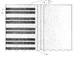
図2は、基板シート1上に複数組の電極7、7’(検知手段)が形成された様子を示す平面図である。本例では、一組の電極7、7’は、2本の電極からなりそれぞれ作用極、対極に相当する。図3は、基板シート1上に電極7が形成された様子を示す側面図である。本例では、電極7はカーボンインクからなり、PETからなる基板シート1上に、スクリーン印刷により形成される。又図2、図3に示すように、本例では、電極7は、折り曲げ線10の一方の側にある基板2上のみに形成され、カバー層3上には形成されていない。
FIG. 2 is a plan view showing a state in which a plurality of sets of
次に、本発明の製造方法の例を説明する。図4aは、図2、図3に示す基板シート1上に電極7が形成された積層体を、折り曲げ線10に平行で、折り曲げ線10から等距離にある2本の線10’に沿って折り曲げ、コの字型に成型したものである。基板シート1は、PETからなり、この成型は160〜250℃の熱を加えて行われ、その後、残留応力を解消するために、折り曲げ部分には、同温度で加熱され熱処理される。熱処理は、コの字型に折り曲げた背の部分をホットプレート上に突き当て、1〜2秒間保持することにより行われる。
Next, the example of the manufacturing method of this invention is demonstrated. FIG. 4 a shows a laminate in which the
一方、溝を有する2枚のスペーサ材4を粘着材5で貼り合せることにより、図4bで示される、溝9’を有するスペーサ層が形成される。このスペーサ層の両面には、UV硬化樹脂5’が塗布され、図4aで示されるコの字型の成型体内に挿入される。挿入を容易にするために、基板シート1とカバー層3の間を拡げて挿入し、その後PETの弾性により閉じ、貼り合せた後、UV照射してUV硬化樹脂5’を硬化して、接着する。その後、中空反応部9に薬剤を塗布することにより、図1で示されるセンサチップが得られる。
On the other hand, the
図5は、本発明の他の製造方法の一工程を示す説明図である。この例では、基板シート1を折り曲げる前に、折り曲げ線10についての一方の側に、粘着材51、52により2枚のスペーサ材4が積層される。積層は、スクリーン印刷によっても行うことができる。この場合は、基板シート上にスペーサ材が直接塗布され、硬化される。粘着材は最上層のみに使用される。
FIG. 5 is an explanatory view showing one step of another manufacturing method of the present invention. In this example, before the
スペーサ材4は溝を有するので、積層により、中空反応部9となる溝9’が形成される。溝9’内に露出している電極7上には、薬剤8が塗布される。又、最上層のスペーサ材4上にはUV硬化樹脂5’が塗布される。次に、PETからなる基板シート1を、折り曲げ線10に平行で折り曲げ線10から等距離にある2本の線10’に沿って、常温で、コの字型に折り曲げた後、残留応力を解消するために、折り曲げ部分を熱処理する。
Since the
熱処理は、常温での折り曲げ後、折り曲げを保持した状態で、折り曲げた背の部分を、表面温度200℃のホットプレートに突き当て、1秒間保持することにより行われる。ホットプレートを用いると、局部的な加熱が容易であり、かつ加熱時間が短くてよいので、生産性と熱による悪影響防止の両者の観点から有利である。薬剤8が塗布された位置は、ホットプレートに突き当てた部分から5mm以上離れていることが望ましい。5mm以上離れておれば、前記の条件で熱処理を行っても、薬剤8が塗布された部分が60℃以上となることはなく、薬剤8が耐熱性の低い酵素の場合でも、熱による酵素の劣化が生じることはない。
The heat treatment is performed by holding the bent back portion against a hot plate having a surface temperature of 200 ° C. and holding it for 1 second after being bent at room temperature and holding the bent state. The use of a hot plate is advantageous in terms of both productivity and prevention of adverse effects due to heat because local heating is easy and the heating time may be short. It is desirable that the position where the
基板シート1をコの字型に折り曲げることにより、基板シート1とスペーサ材4が貼り合される。次にUV照射してスペーサ材4上のUV硬化樹脂5’を硬化することにより、接着がされ、本発明のセンサチップが形成される。
The
なお、前記の例で、粘着材5、51、52としては、ゴム系粘着材、アクリル系粘着材、シリコーン系粘着材等を用いることができる。スペーサ材4としては、PET等を用いることができる。又スクリーン印刷できるスペーサ材としては、ウレタン樹脂、エポキシ樹脂、変性ポリイミド樹脂、アクリル樹脂等が用いられる。
In the above example, as the
1 基板シート
2 基板
3 カバー層
4 スペーサ材
5、51、52 粘着材
5’ UV硬化樹脂
6 スペーサ層
7、7’ 電極
8 薬剤
9 中空反応部
9’ 溝
10 折り曲げ線
DESCRIPTION OF
Claims (7)
A plurality of detection means are formed in parallel in the direction of the fold line, and the obtained laminate is 1 perpendicular to the fold line so that at least one set of detection means is included in each sensor chip. 7. The method of manufacturing a sensor chip according to claim 4, wherein the sensor chip is cut along a plurality of straight lines.
Priority Applications (8)
| Application Number | Priority Date | Filing Date | Title |
|---|---|---|---|
| JP2004184187A JP2006010352A (en) | 2004-06-22 | 2004-06-22 | Sensor chip and its manufacturing method |
| CA002571648A CA2571648A1 (en) | 2004-06-22 | 2005-06-21 | Sensor chip and manufacturing method thereof |
| PCT/JP2005/011323 WO2005124329A1 (en) | 2004-06-22 | 2005-06-21 | Sensor chip and manufacturing method thereof |
| US11/630,475 US20080248457A1 (en) | 2004-06-22 | 2005-06-21 | Sensor Chip and Manufacturing Method Thereof |
| KR1020067026904A KR20070027603A (en) | 2004-06-22 | 2005-06-21 | Sensor chip and manufacturing method thereof |
| AU2005255305A AU2005255305A1 (en) | 2004-06-22 | 2005-06-21 | Sensor chip and manufacturing method thereof |
| EP05753492A EP1760460A1 (en) | 2004-06-22 | 2005-06-21 | Sensor chip and manufacturing method thereof |
| NO20065955A NO20065955L (en) | 2004-06-22 | 2006-12-21 | Sensor chip and method in its manufacture |
Applications Claiming Priority (1)
| Application Number | Priority Date | Filing Date | Title |
|---|---|---|---|
| JP2004184187A JP2006010352A (en) | 2004-06-22 | 2004-06-22 | Sensor chip and its manufacturing method |
Publications (1)
| Publication Number | Publication Date |
|---|---|
| JP2006010352A true JP2006010352A (en) | 2006-01-12 |
Family
ID=35777789
Family Applications (1)
| Application Number | Title | Priority Date | Filing Date |
|---|---|---|---|
| JP2004184187A Pending JP2006010352A (en) | 2004-06-22 | 2004-06-22 | Sensor chip and its manufacturing method |
Country Status (1)
| Country | Link |
|---|---|
| JP (1) | JP2006010352A (en) |
Cited By (5)
| Publication number | Priority date | Publication date | Assignee | Title |
|---|---|---|---|---|
| WO2006078010A1 (en) * | 2005-01-24 | 2006-07-27 | Sumitomo Electric Industries, Limited | Sensor chip |
| JP2007205988A (en) * | 2006-02-03 | 2007-08-16 | National Institute Of Advanced Industrial & Technology | Biosensor and its manufacturing method |
| JP2007205989A (en) * | 2006-02-03 | 2007-08-16 | National Institute Of Advanced Industrial & Technology | Biosensor and its manufacturing method |
| JP2007248274A (en) * | 2006-03-16 | 2007-09-27 | National Institute Of Advanced Industrial & Technology | Biosensor and manufacturing method therefor |
| JP2009069096A (en) * | 2007-09-18 | 2009-04-02 | Panasonic Corp | Electrode substrate, microorganism using it, and measuring device of particulate |
Citations (5)
| Publication number | Priority date | Publication date | Assignee | Title |
|---|---|---|---|---|
| JP2001021528A (en) * | 1999-07-02 | 2001-01-26 | Akebono Brake Res & Dev Center Ltd | Electrode type biosensor |
| WO2002008743A1 (en) * | 2000-07-24 | 2002-01-31 | Matsushita Electric Industrial Co., Ltd. | Biosensor |
| JP2003529061A (en) * | 2000-03-28 | 2003-09-30 | ダイアビ−ティ−ズ・ダイアグノスティックス・インコ−ポレイテッド | Continuous manufacturing method of disposable electrochemical sensor |
| JP2004506178A (en) * | 2000-06-30 | 2004-02-26 | ベーエムエス センサー テヒノロギー エスアー | Biosensor and manufacturing method thereof |
| JP2005233917A (en) * | 2003-07-25 | 2005-09-02 | National Institute Of Advanced Industrial & Technology | Biosensor and method for manufacturing the same |
-
2004
- 2004-06-22 JP JP2004184187A patent/JP2006010352A/en active Pending
Patent Citations (5)
| Publication number | Priority date | Publication date | Assignee | Title |
|---|---|---|---|---|
| JP2001021528A (en) * | 1999-07-02 | 2001-01-26 | Akebono Brake Res & Dev Center Ltd | Electrode type biosensor |
| JP2003529061A (en) * | 2000-03-28 | 2003-09-30 | ダイアビ−ティ−ズ・ダイアグノスティックス・インコ−ポレイテッド | Continuous manufacturing method of disposable electrochemical sensor |
| JP2004506178A (en) * | 2000-06-30 | 2004-02-26 | ベーエムエス センサー テヒノロギー エスアー | Biosensor and manufacturing method thereof |
| WO2002008743A1 (en) * | 2000-07-24 | 2002-01-31 | Matsushita Electric Industrial Co., Ltd. | Biosensor |
| JP2005233917A (en) * | 2003-07-25 | 2005-09-02 | National Institute Of Advanced Industrial & Technology | Biosensor and method for manufacturing the same |
Cited By (8)
| Publication number | Priority date | Publication date | Assignee | Title |
|---|---|---|---|---|
| WO2006078010A1 (en) * | 2005-01-24 | 2006-07-27 | Sumitomo Electric Industries, Limited | Sensor chip |
| JP2007205988A (en) * | 2006-02-03 | 2007-08-16 | National Institute Of Advanced Industrial & Technology | Biosensor and its manufacturing method |
| JP2007205989A (en) * | 2006-02-03 | 2007-08-16 | National Institute Of Advanced Industrial & Technology | Biosensor and its manufacturing method |
| JP4649594B2 (en) * | 2006-02-03 | 2011-03-09 | 独立行政法人産業技術総合研究所 | Biosensor and manufacturing method thereof |
| JP4665135B2 (en) * | 2006-02-03 | 2011-04-06 | 独立行政法人産業技術総合研究所 | Biosensor manufacturing method |
| JP2007248274A (en) * | 2006-03-16 | 2007-09-27 | National Institute Of Advanced Industrial & Technology | Biosensor and manufacturing method therefor |
| JP4635260B2 (en) * | 2006-03-16 | 2011-02-23 | 独立行政法人産業技術総合研究所 | Biosensor and manufacturing method thereof |
| JP2009069096A (en) * | 2007-09-18 | 2009-04-02 | Panasonic Corp | Electrode substrate, microorganism using it, and measuring device of particulate |
Similar Documents
| Publication | Publication Date | Title |
|---|---|---|
| JP4038575B2 (en) | Biosensor, biosensor device or biosensor storage method | |
| WO2005124329A1 (en) | Sensor chip and manufacturing method thereof | |
| WO2007046335A1 (en) | Sensor chip and method for producing the same | |
| WO2007049646A1 (en) | Sensor chip and sensor system | |
| JP4807493B2 (en) | Sensor chip and manufacturing method thereof | |
| JP2007108104A (en) | Sensor chip and manufacturing method therefor | |
| JP2006010352A (en) | Sensor chip and its manufacturing method | |
| TW201346256A (en) | Co-facial analytical test strip with stacked unidirectional contact pads and inert carrier substrate | |
| JP2006047287A (en) | Sensor chip and production method therefor | |
| JP5289666B2 (en) | Sensor chip assembly and manufacturing method thereof | |
| KR101359750B1 (en) | Method for fabricating bio sensor strip using a paper and structure of the same | |
| JP2007163220A (en) | Connected type biosensor chip | |
| JP4518846B2 (en) | Sensor chip manufacturing method and sensor chip | |
| JP4665135B2 (en) | Biosensor manufacturing method | |
| WO2006078022A1 (en) | Sensor chip manufacturing method and sensor chip | |
| JP4036384B2 (en) | Biosensor manufacturing method | |
| JP2007101377A (en) | Sensor chip and manufacturing method therefor | |
| CN101006337A (en) | Sensor chip and production method therefor | |
| WO2006078010A1 (en) | Sensor chip | |
| US20090050986A1 (en) | Method for Fabricating Sensor Chip, and Sensor Chip | |
| JP2007121018A (en) | Sensor chip and its manufacturing method | |
| Hauke | An Integrated System for Sweat Stimulation, Sampling and Sensing | |
| JP2007205987A (en) | Biosensor and its manufacturing method |
Legal Events
| Date | Code | Title | Description |
|---|---|---|---|
| A621 | Written request for application examination |
Free format text: JAPANESE INTERMEDIATE CODE: A621 Effective date: 20070126 |
|
| A521 | Written amendment |
Free format text: JAPANESE INTERMEDIATE CODE: A821 Effective date: 20070126 |
|
| A131 | Notification of reasons for refusal |
Free format text: JAPANESE INTERMEDIATE CODE: A131 Effective date: 20100105 |
|
| A02 | Decision of refusal |
Free format text: JAPANESE INTERMEDIATE CODE: A02 Effective date: 20100511 |