JP2006007323A - Tool for setting blind bolt - Google Patents
Tool for setting blind bolt Download PDFInfo
- Publication number
- JP2006007323A JP2006007323A JP2005176150A JP2005176150A JP2006007323A JP 2006007323 A JP2006007323 A JP 2006007323A JP 2005176150 A JP2005176150 A JP 2005176150A JP 2005176150 A JP2005176150 A JP 2005176150A JP 2006007323 A JP2006007323 A JP 2006007323A
- Authority
- JP
- Japan
- Prior art keywords
- spring
- jaw
- head
- mandrel
- collet
- Prior art date
- Legal status (The legal status is an assumption and is not a legal conclusion. Google has not performed a legal analysis and makes no representation as to the accuracy of the status listed.)
- Pending
Links
Images


Classifications
-
- B—PERFORMING OPERATIONS; TRANSPORTING
- B21—MECHANICAL METAL-WORKING WITHOUT ESSENTIALLY REMOVING MATERIAL; PUNCHING METAL
- B21J—FORGING; HAMMERING; PRESSING METAL; RIVETING; FORGE FURNACES
- B21J15/00—Riveting
- B21J15/02—Riveting procedures
- B21J15/04—Riveting hollow rivets mechanically
- B21J15/043—Riveting hollow rivets mechanically by pulling a mandrel
-
- B—PERFORMING OPERATIONS; TRANSPORTING
- B25—HAND TOOLS; PORTABLE POWER-DRIVEN TOOLS; MANIPULATORS
- B25B—TOOLS OR BENCH DEVICES NOT OTHERWISE PROVIDED FOR, FOR FASTENING, CONNECTING, DISENGAGING OR HOLDING
- B25B13/00—Spanners; Wrenches
- B25B13/02—Spanners; Wrenches with rigid jaws
- B25B13/06—Spanners; Wrenches with rigid jaws of socket type
-
- B—PERFORMING OPERATIONS; TRANSPORTING
- B21—MECHANICAL METAL-WORKING WITHOUT ESSENTIALLY REMOVING MATERIAL; PUNCHING METAL
- B21J—FORGING; HAMMERING; PRESSING METAL; RIVETING; FORGE FURNACES
- B21J15/00—Riveting
- B21J15/02—Riveting procedures
- B21J15/04—Riveting hollow rivets mechanically
- B21J15/043—Riveting hollow rivets mechanically by pulling a mandrel
- B21J15/045—Riveting hollow rivets mechanically by pulling a mandrel and swaging locking means, i.e. locking the broken off mandrel head to the hollow rivet
-
- B—PERFORMING OPERATIONS; TRANSPORTING
- B21—MECHANICAL METAL-WORKING WITHOUT ESSENTIALLY REMOVING MATERIAL; PUNCHING METAL
- B21J—FORGING; HAMMERING; PRESSING METAL; RIVETING; FORGE FURNACES
- B21J15/00—Riveting
- B21J15/10—Riveting machines
- B21J15/105—Portable riveters
-
- B—PERFORMING OPERATIONS; TRANSPORTING
- B25—HAND TOOLS; PORTABLE POWER-DRIVEN TOOLS; MANIPULATORS
- B25B—TOOLS OR BENCH DEVICES NOT OTHERWISE PROVIDED FOR, FOR FASTENING, CONNECTING, DISENGAGING OR HOLDING
- B25B23/00—Details of, or accessories for, spanners, wrenches, screwdrivers
- B25B23/02—Arrangements for handling screws or nuts
-
- G—PHYSICS
- G09—EDUCATION; CRYPTOGRAPHY; DISPLAY; ADVERTISING; SEALS
- G09G—ARRANGEMENTS OR CIRCUITS FOR CONTROL OF INDICATING DEVICES USING STATIC MEANS TO PRESENT VARIABLE INFORMATION
- G09G5/00—Control arrangements or circuits for visual indicators common to cathode-ray tube indicators and other visual indicators
- G09G5/36—Control arrangements or circuits for visual indicators common to cathode-ray tube indicators and other visual indicators characterised by the display of a graphic pattern, e.g. using an all-points-addressable [APA] memory
- G09G5/363—Graphics controllers
-
- G—PHYSICS
- G09—EDUCATION; CRYPTOGRAPHY; DISPLAY; ADVERTISING; SEALS
- G09G—ARRANGEMENTS OR CIRCUITS FOR CONTROL OF INDICATING DEVICES USING STATIC MEANS TO PRESENT VARIABLE INFORMATION
- G09G5/00—Control arrangements or circuits for visual indicators common to cathode-ray tube indicators and other visual indicators
- G09G5/36—Control arrangements or circuits for visual indicators common to cathode-ray tube indicators and other visual indicators characterised by the display of a graphic pattern, e.g. using an all-points-addressable [APA] memory
- G09G5/39—Control of the bit-mapped memory
- G09G5/395—Arrangements specially adapted for transferring the contents of the bit-mapped memory to the screen
- G09G5/397—Arrangements specially adapted for transferring the contents of two or more bit-mapped memories to the screen simultaneously, e.g. for mixing or overlay
-
- G—PHYSICS
- G09—EDUCATION; CRYPTOGRAPHY; DISPLAY; ADVERTISING; SEALS
- G09G—ARRANGEMENTS OR CIRCUITS FOR CONTROL OF INDICATING DEVICES USING STATIC MEANS TO PRESENT VARIABLE INFORMATION
- G09G2340/00—Aspects of display data processing
- G09G2340/12—Overlay of images, i.e. displayed pixel being the result of switching between the corresponding input pixels
-
- Y—GENERAL TAGGING OF NEW TECHNOLOGICAL DEVELOPMENTS; GENERAL TAGGING OF CROSS-SECTIONAL TECHNOLOGIES SPANNING OVER SEVERAL SECTIONS OF THE IPC; TECHNICAL SUBJECTS COVERED BY FORMER USPC CROSS-REFERENCE ART COLLECTIONS [XRACs] AND DIGESTS
- Y10—TECHNICAL SUBJECTS COVERED BY FORMER USPC
- Y10T—TECHNICAL SUBJECTS COVERED BY FORMER US CLASSIFICATION
- Y10T29/00—Metal working
- Y10T29/53—Means to assemble or disassemble
- Y10T29/53709—Overedge assembling means
- Y10T29/53717—Annular work
- Y10T29/53726—Annular work with second workpiece inside annular work one workpiece moved to shape the other
- Y10T29/5373—Annular work with second workpiece inside annular work one workpiece moved to shape the other comprising driver for snap-off-mandrel fastener; e.g., Pop [TM] riveter
- Y10T29/53739—Pneumatic- or fluid-actuated tool
Landscapes
- Engineering & Computer Science (AREA)
- Mechanical Engineering (AREA)
- Physics & Mathematics (AREA)
- Computer Hardware Design (AREA)
- General Physics & Mathematics (AREA)
- Theoretical Computer Science (AREA)
- Computer Graphics (AREA)
- Insertion Pins And Rivets (AREA)
- Controls And Circuits For Display Device (AREA)
- Gripping On Spindles (AREA)
- Springs (AREA)
- Quick-Acting Or Multi-Walled Pipe Joints (AREA)
- Wire Processing (AREA)
Abstract
Description
[関連出願(優先権主張)]
この出願は、2004年6月22日に出願された米国仮出願第60/582,210号の利益を主張する。
[Related applications (priority claim)]
This application claims the benefit of US Provisional Application No. 60 / 582,210, filed June 22, 2004.
この発明は、一般にブラインドボルト(盲ボルト、blind bolts)を設置するための工具に関し、特に以下で論じられるような従来技術の問題点を克服するために異なる等級のスプリングを有したブラインドボルト設置工具に関する。 The present invention relates generally to tools for installing blind bolts, and in particular, blind bolt installation tools having different grades of springs to overcome the problems of the prior art as discussed below. About.
図1〜10は、図面に示されているようなブラインドボルトを設置するための2つの異なる引き込みヘッド10a(図1〜5)および10b(図6〜10)を示している(米国特許第4,432,679号および4,844,673号も参照されたい。それらの全体は、参照によりここに組み入れられる)。図示されているように、引き込みヘッド10a,10bは、ブラインドボルトと共動するように構成される。ブラインドボルトは、マンドレル28a,28bと、シフトワッシャ62と、スリーブ63とを有する。マンドレルは、ファスナー12a,12bを設置するために引き込まれ、マンドレル28a,28bは設置中に折れる。
FIGS. 1-10 show two
一般に、ファスナーが挿入される前にジョーを配置することに関して、引き込みヘッドは、「オープン(常開型)ジョー」設計と「クローズド(常閉型)ジョー」設計の2つのカテゴリーに分類されうる。双方の設計において、1組のジョーがファスナーのマンドレルを把持する。常開型ジョー設計のジョーは、通常は開放されていて、マンドレル上で閉じられなければならない。これに対し、常閉型ジョー設計のジョーは、通常は互いに接近し過ぎていて、それらの間にマンドレルを挿入することが難しい。それ故、ジョーは、マンドレルを挿入するために、開放されなければならない。 In general, with respect to positioning the jaws before the fasteners are inserted, the retraction heads can be divided into two categories: “open (normally open) jaws” design and “closed (normally closed) jaws” design. In both designs, a set of jaws grips the mandrel of the fastener. A jaw with a normally open jaw design is normally open and must be closed on a mandrel. In contrast, jaws with normally closed jaw designs are usually too close to each other and it is difficult to insert a mandrel between them. Therefore, the jaw must be opened in order to insert the mandrel.
図1は、常閉型ジョー設計の引き込みヘッド10aを示しているのに対し、図6は、常開型ジョー設計の引き込みヘッド10bを示している。各引き込みヘッドは、設置工具と螺合されるように構成されている。この設置工具は、明瞭化のために図面から省略されている。設置工具が引き込みヘッド10aまたは10bと螺合され、そして設置工具が作動されるときに、設置工具は引き込みヘッドを動作させて、ファスナーを設置する。
FIG. 1 shows a retracting
図1に示されるように、常閉型ジョー式の引き込みヘッド10aは、引き込みヘッドの長軸16を中心として1組のジョー14aを備える(典型的な1組は2または3つのジョーを有する)。1組内の各ジョーは、傾斜または円錐形部分18を外面20上に、また鋸歯状部分22を内面24上に有する。鋸歯状部分22は、ファスナーまたはブラインドボルト12aのマンドレル28上に設けられた対応する鋸歯状部26を把持するように係合する。
As shown in FIG. 1, the normally closed
ジョー14aは、コレット32a内に設けられたテーパ部30内に配設されている。図1に示されているように、ジョー14aが最前方位置にあるときに、ジョー14aによって規定される内径34は、ジョー14a内に挿入されるファスナー12aのマンドレル28の直径36よりも概ね小さい。ファスナー12aは、前述した米国特許第4,432,679号および4,844,673号や多数の他の従来技術特許に概ね示されているように、通常のブラインドボルト設計である。従って、ジョー14aは、「常閉型」であると言われる。コレット32a内には、設置工具のヘッドピストンとの係合用に、ネジ部38が設けられている。コレット32aは概ね円筒形であって、主かる内孔40を有する。ジョー14aとジョーフォロワー42aとフォロワースプリング44aが、コレット32a内に配設されている。ジョーフォロワー42aは、ジョー14aを概ね定位置に保持する。ジョーフォロワー42aもまた概ね円筒形であって、長尺な透孔46を有する。この透孔は、ブラインドボルトまたはファスナー12aの折れたステムまたはマンドレル28aを受け入れるように構成されている。
The
ジョーフォロワー42aは、フォロワースプリング44aによるスプリング負荷を受ける。フォロワースプリング44aの一端48は、ジョーフォロワー42aの外面52上の肩部50に接触する。これに対し、設置工具が引き込みヘッド10aと係合されているときに、フォロワースプリング44aの他端52は設置工具と接触する。フォロワースプリング44aは、ファスナー12aのマンドレル28aが設置中に折れたときに、ショックアブソーバー(緩衝器)として効果的に作用することで、ジョーフォロワー42aが急速に後向きに加速して他の部品に衝突することがないようにする。コレット32aは、スリーブ54a内に移動可能に配設されている。ネジ付きの開口56が、スリーブ54aの端部58に設けられ、ノーズピース60aがネジ付きの開口56内に螺合されている。
The
動作時に、図2に示されるように、ファスナー12aのマンドレル28aがノーズピース60aに挿入されると、マンドレル28aは、ジョー14aを(スプリング44aによって与えられる)スプリング負荷に抗して開く。マンドレル28aは、図3に示されるように、ファスナー12aのシフトワッシャー62がノーズピース60aに底をつけるか接触するまで、ノーズピース60a内に挿入される。ジョー14aはテーパ部30内に座しているので、ジョー14aは、それらが拡張するときに、それらの鋸歯状部22がマンドレル28aの鋸歯状部26と整列するまで、後退する必要がある。ジョー14aが開くと、マンドレル28aの鋸歯状部26は、ジョー14aの鋸歯状部22を擦って摩耗させる。オペレータ効果と、スリーブ54aおよびマンドレル28a間でのファスナー分解の可能性を最小化するために、フォロワースプリング44aは、比較的小さなスプリングレートを有するように構成されることが好ましい。
In operation, as shown in FIG. 2, when the
図4に示されるように、工具が作動されると(即ち、工具のトリガが押されると)、設置工具のヘッドピストンに螺着されているコレット32aは、負荷を受けて後退する。ヘッドピストン(図示せず)の移動は、工具の「ストローク」として知られており、この「ストローク」は、図4の矢印62で識別されている。コレット32aのテーパ部30は、工具の引き込み力をジョー14aに伝達して、マンドレル28aを把持させる。従来と同様に、そして前述した特許に述べられているように、マンドレル28aがファスナー12aのスリーブ63に対して移動するときに、ファスナー12aはスリーブ63を変形し、且つロック用カラーをセットする。マンドレル28aが破壊切り込み部で破砕または破壊するまで、引き込み力は継続して設置を完了する。フォロワースプリング44aはショックアブソーバーとして作用しなければならないので、ファスナーの破壊負荷は比較的小さなものでなければならない。このときスプリング44aは、永久「ひずみ」し過ぎることなしに、設置の運動エネルギを吸収できる。マンドレル28aが折れたときに、マンドレル28aは依然としてジョー14aによって保持されている。
As shown in FIG. 4, when the tool is operated (ie, when the trigger of the tool is pushed), the
設置工具のトリガが解放されたときに、ヘッドピストンとコレット32aは、図5に示されるように、それらのホームポジションに戻る。図示のように、折れたマンドレル28aは、スプリング負荷によって、依然としてジョー14a内に保持されている。次のファスナーが挿入されるときに、そのマンドレルが、ジョー14aを通して前回設置されたファスナーの折れたマンドレルを押し、より多くの摩耗を生じさせる。
When the installation tool trigger is released, the head piston and
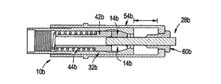
図6は、常開型ジョー式の引き込みヘッド10bを示している。この設計は、常閉型ジョー式の引き込みヘッドと同様であって、スリーブ54bと、コレット32bと、ジョー14bと、ジョーフォロワー42bと、フォロワースプリング44bと、ノーズピース60bとを含んでいる。しかしながら、常開型ジョー設計のジョー14bは、それらの最前方位置またはホームポジションで開かれる。このとき、ジョー14bによって形成された内部形状は、挿入されるファスナーの直径よりも大きい。これは通常、ノーズピース60bの後部突起64によって達成される。この後部突起は、コレット32b内に突出して、引き込みヘッドがその「ホーム」ポジションにあるときにジョー14bを開くように構成されている。それ故、ジョー14bは、ファスナー12bのマンドレルまたはステム28bが挿入される前に開放され、マンドレル28bが抵抗無く挿入されるようにし、また必要であれば、取り外されるようにする。
FIG. 6 shows a normally open jaw
図7は、引き込みヘッド10b内に配置されたマンドレル28bを示している。マンドレル28bをこの位置に配置することに関与する抵抗はない。何故ならば、ジョー14bの各々の直径70は、マンドレル28bの直径よりも大きいので、真空力によってファスナー12bもまた挿入され、維持されるからである。この点において、ジョー14bは、ノーズピース60bの後部突出部64によって開かれる。ジョー14bは、後部突起64によって後退させられ、それ故スプリング負荷によってコレット32bのテーパ部72に対し外向きに開かれる。この点において、ファスナー12bは、引き込みヘッド10bから取り外される。何故ならば、ジョー14bはマンドレル28bを把持していないからである。
FIG. 7 shows a
リベット工具が作動されると、コレット32bは、図8に示されるように、ノーズピース60bから離れて後退し始める。コレット32b内へのノーズピース60bの突起64が減少するにつれて、ジョー14はコレット32bのテーパ部72内で閉じ始める。コレット32bがノーズピース60bの後部突起64から引き下がるにつれて、ジョーの組はスプリング負荷によって前方へ押されてステム28b上で閉じる。ステム28bが細いほど、ストロークを大きくして、ジョー14bを接触させる。その後、マンドレル28bは、ファスナー12bが設置されるまで引き込まれる。
When the rivet tool is activated, the
図9に示されているように、工具がそのストロークを完了するときに、マンドレル28bは破壊し、コレット32bはその極限位置まで移動する。常開型ジョー式の引き込みヘッド設計を使用してファスナーを設置するには、常閉型ジョー設計によって必要とされるよりも多くのストロークが必要とされる。マンドレル28bが破壊した後に、マンドレル28bはジョー14bによって依然として保持される。
As shown in FIG. 9, when the tool completes its stroke, the
図10に示されているように、工具サイクルの終了時に、コレット32bは、その「ホーム」ポジションに戻るので、ノーズピース60bはジョー14bに再度接触して、それを開き、マンドレル28bが解放されるようにする。折れたステム28bは、重力によって自由に移動するか、あるいは真空力によって引き抜かれる。いずれの場合にも、ジョー14bは、その引き抜きに起因する摩耗、または次のファスナーの挿入による摩耗を経験することがない。
As shown in FIG. 10, at the end of the tool cycle, the
マンドレル28bは、挿入時にジョー14bを開く必要はないので(図7参照)、フォロワースプリング44bは、常閉型ジョー設計におけるよりも強いものとなり得る。このスプリング44bは、より多くの運動エネルギを吸収することができるので、使用されるファスナーの破壊負荷もまた、常閉型ジョー設計におけるよりも高くなる。しかしながら、常開型ジョー設計で使用されるファスナーのマンドレル28bは、長いノーズピース60bを超えて延びるように十分に長く、ジョー14bがそれを把持できるように、はるかに長くなければならない。また、ジョー14bがマンドレル28b上で閉じる間に使用される工具のストロークは無駄になる。
Because the
典型的に、図1〜5に示されているような常閉型ジョー設計は、低破壊負荷のファスナーの設置に使用される。常閉型ジョー設計は、比較的低いスプリングレートの内部スプリング(即ち、上記で論じ、且つ図1〜5内で識別されるような部品番号44a)を典型的に使用する。この構成は、異なるサイズの直径で比較的短いステムのファスナーの設置を可能にする。これに対し、図6〜10に示されているような常開型ジョー設計は、典型的に単一サイズの直径で高破壊負荷のファスナーの設置に使用される。常開型ジョー設計は、比較的高いスプリングレートの内部スプリング(即ち、上記で論じ、且つ図1〜5内で識別されるような部品番号44b)を典型的に使用する。この構成は、異なるサイズの直径の設置を非常に困難にすると共に、非常に短いステムのファスナーの設置を不可能にする。
Typically, a normally closed jaw design, such as that shown in FIGS. 1-5, is used to install a low destructive load fastener. The normally closed jaw design typically uses a relatively low spring rate internal spring (ie,
[目的および要約]
本発明の一実施形態の目的は、幅広い範囲のマンドレル径に関連して使用できる引き込みヘッドを提供することである。
[Purpose and Summary]
An object of one embodiment of the present invention is to provide a retracting head that can be used in connection with a wide range of mandrel diameters.
本発明の一実施形態のもう1つの目的は、特別に短いステムを有したファスナーに適応するだけでなく、高慣性負荷に適応する引き込みヘッドを提供することである。 Another object of an embodiment of the present invention is to provide a retraction head that not only accommodates fasteners with extra short stems, but also accommodates high inertia loads.
簡単に、そして前述した目的の少なくとも1つに従って、本発明の一実施形態は、異なるスプリングレートの2つのスプリングを有した引き込みヘッドを提供する。第1の高いレートのスプリングは、引き込みヘッドが高慣性負荷に適応できるようにするものであり、第2の低いレートのスプリングは、引き込みヘッドが幅広い範囲のマンドレル径に関連して使用できるようにするものである。 Briefly and in accordance with at least one of the above-mentioned objects, an embodiment of the present invention provides a retraction head having two springs with different spring rates. The first high rate spring allows the retraction head to adapt to high inertia loads and the second low rate spring allows the retraction head to be used in connection with a wide range of mandrel diameters. To do.
本発明の具体的な実施形態は、設置工具との係合用に構成された引き込みヘッドを提供する。この引き込みヘッドは、設置工具に係合可能な外側本体を備える。この外側本体は、スリーブアダプタに螺合するスリーブと、このスリーブをスリーブアダプタに対して固定するジャムナットとを有する。コレットは、引っ張り棒アダプタに螺合する。コレットと引っ張り棒アダプタは、スリーブ内にスライド可能に配設されている。コレット内には、1組のジョーが、コレット内に設けられたテーパ部の付近に配設されている。コレット内にはまた、ジョーフォロワーが配設され、ジョーと接触可能に係合している。コレット内には、スプリング保持部が配設され、2つのスプリングと係合している。具体的には、第1のスプリングは、引っ張り棒アダプタとスプリング保持部との間に配設され、第2のスプリングは、スプリング保持部とジョーフォロワーとの間に配設されている。第1のスプリングは、第2のスプリングよりも高い等級を有する。第1のスプリングは、慣性負荷に適応して構成されている。これに対し、第2のスプリングは、スリーブの端部に設けられた開口部に異なる直径のマンドレルを挿入することによって比較的容易に克服されるように、ジョーを閉じるものとして構成されている。 Specific embodiments of the present invention provide a retraction head configured for engagement with an installation tool. The retracting head includes an outer body that is engageable with the installation tool. The outer body includes a sleeve that is screwed to the sleeve adapter, and a jam nut that fixes the sleeve to the sleeve adapter. The collet is screwed onto the drawbar adapter. The collet and drawbar adapter are slidably disposed within the sleeve. In the collet, a set of jaws is disposed in the vicinity of a tapered portion provided in the collet. A jaw follower is also disposed within the collet and engages the jaw so as to be in contact therewith. A spring holding part is disposed in the collet and is engaged with two springs. Specifically, the first spring is disposed between the pull rod adapter and the spring holding portion, and the second spring is disposed between the spring holding portion and the jaw follower. The first spring has a higher grade than the second spring. The first spring is configured to adapt to the inertial load. In contrast, the second spring is configured to close the jaws so that it can be overcome relatively easily by inserting mandrels of different diameters into openings provided at the end of the sleeve.
発明の構造および動作の組織および手法は、その更なる目的および利点と共に、添付の図面に関連してなされる以下の説明を参照することによって、最も良く理解される。図面では、同様の参照符号は同様の要素を識別している。 The organization and approach of the structure and operation of the invention, together with its further objects and advantages, are best understood by referring to the following description, taken in conjunction with the accompanying drawings. In the drawings, like reference numbers identify like elements.
[説明]
本発明は、異なる形の実施形態に受け入れ可能であるが、その実施形態が図面に示され、ここで詳細に説明される。但し、この説明は、発明の原理の例示と考えられるべきものであって、この発明を、ここに図示され説明されたものに限定することを意図したものではない、と理解されるべきである。
[Explanation]
While the invention is amenable to different forms of embodiments, such embodiments are shown in the drawings and will herein be described in detail. However, it should be understood that this description is to be considered as illustrative of the principles of the invention and is not intended to limit the invention to what is shown and described herein. .
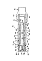
図11は、本発明の一実施形態に係る引き込みヘッド100を示している。この引き込みヘッド100は、異なるスプリングレートの2つのスプリングを有している。第1の高いレートのスプリング174は、引き込みヘッド100が高慣性負荷に適応できるようにするものであり、第2の低いレートのスプリング170は、引き込みヘッド100が幅広い範囲のマンドレル径に関連して使用できるようにするものである。
FIG. 11 shows a
引き込みヘッド100は、設置工具との係合用に構成されている。具体的に、引き込みヘッド100は、設置工具に係合可能な外側本体106を備える。この外側本体106は、外ネジ部110を有したスリーブ108と、対応する内ネジ部114を有したスリーブアダプタ112とからなる。スリーブ108のネジ部110は、スリーブアダプタ112のネジ部114と螺合する。ジャムナット116は、スリーブ108のネジ部110上に螺合可能であって、スリーブ108をスリーブアダプタ112に対して固定する。具体的には、組立中に、ジャムナット116はスリーブ108上に螺合し、スリーブ108はスリーブアダプタ112に螺入し、ジャムナット116はスリーブアダプタ112と接触しながら回転させられる。スリーブ108とスリーブアダプタ112とジャムナット116は、設置過程中は静止し続けるサブアセンブリを構成する。スリーブアダプタ112は、設置工具のヘッドシリンダに直接螺入するように構成された別の外ネジ部118を有する。引き込みヘッド100は、ノーズピースを有せず、そしてスリーブ108の端部122に開口部120だけを有することが好ましい。スリーブ108は、2つの外径124および126を有し、小さい外径126は、制限された面積への最大可能アクセス用作業端部にあることが好ましい。
The retracting
コレット128と引っ張り棒アダプタ130がスリーブ108内に配設されている。具体的には、コレット128は内ネジ部132を有する。この内ネジ部は、引っ張り棒アダプタ130上の対応する外ネジ部134と螺合する。コレット128と引っ張り棒アダプタ130は、以下で更に十分に説明されるように、スリーブ108に対して移動可能である。
A
コレット128内には、ジョー136の組(好ましくは、3つのジョーの組)が、引き込みヘッド100の前端128の付近であって、しかもコレット128内に設けられた内側テーパ部140の付近に配設されている。1組内の各ジョー136は、傾斜または円錐形部分142を外面144上に、また鋸歯状部分146を内面148上に有する。鋸歯状部分146は、ファスナーまたはブラインドボルト154のマンドレル152上に設けられた対応する鋸歯状部150を把持しながら係合するように構成されている。3つのジョー136の各々が、図17に示されるように「V」溝構成155を有して、ジョー136が異なる直径のファスナーマンドレルを把持できるようにすることが好ましい。ジョー136が、図11に示されるように最前方位置にあるときに、ジョー136によって規定される内径156は、ジョー136に挿入されるファスナー154のマンドレル152の直径158よりも概ね小さい。この故に、ジョー136は「常閉型」と言われる。
Within the
コレット128内にはまた、ジョーフォロワー162が配設され、ジョー136と接触可能に係合して、ジョー136を定位置に効果的に保持している。ジョーフォロワー162の端部164は、引っ張り棒アダプタ130内に設けられた孔166中に延びている。ジョーフォロワー162は概ね円筒形であって、長尺な透孔168を有する。この透孔は、ブラインドボルトまたはファスナー154の折れたステムまたはマンドレル152を受け入れるように構成されている。ジョーフォロワー162は、スプリング170によるスプリング負荷を受ける。
A
コレット128内には、スプリング保持部172が配設され、スプリング170および174と係合している。具体的には、第1のスプリング174は、引っ張り棒アダプタ130とスプリング保持部172との間に配設され、第2のスプリング170は、スプリング保持部172とジョーフォロワー162上に設けられた肩部176との間に配設されている。第1のスプリング174は、第2のスプリング170よりも高い等級を有する。第1のスプリング174は、ファスナー設置中の慣性負荷に適応して構成されている。これに対し、第2のスプリング170は、引き込みヘッド100の端部122に設けられた開口部120に異なる直径のマンドレルを挿入することによって比較的容易に克服されるように、ジョー136を閉じるものとして構成されている。
A
ジョーフォロワー162は、スプリング保持部172内に座するフォロワースプリング170によって、ジョー136の背面に接する負荷を与えられる。スプリング保持部172は、スプリング保持部172の背面179に作用する重スプリング174によって、コレット128内の肩部178に押しつけられる。重スプリング174の逆端部180は、引っ張り棒アダプタ130の前面182に接触する。両スプリング170および174は、引き込みヘッドの「ホーム」ポジションに圧縮されて、内部部品に前負荷を与える。これらの内部部品は、ファスナー設置サイクル中に設置ツールのヘッドピストンと共に移動するサブアセンブリを含む。
The
図11に示されるような引き込みヘッドは、その「ホーム」ポジションに示されている。即ち、引き込みヘッドは、それが取り付けられる設置工具が作動される前に、位置決めされている。フォロワースプリング170は、ジョー136を位置決め状態に保つ前負荷をジョーフォロワー162上に維持する。重スプリング174は、前負荷をスプリング保持部172上に維持する。しかしながら、スプリング保持部172が肩部178に対して底をつけるので、重スプリング174からの負荷は、ジョーフォロワー162には伝達されない。この特徴は、2つのスプリングの機能の分離を可能とする。即ち、フォロワースプリング170は、比較的低いスプリングレートを有して、ジョー136を定位置に保持する。この場合、オペレータは、ファスナー154を引き込みヘッド120の端部122の開口部120内に挿入することに、過剰な力を働かせる必要がない。
The retracting head as shown in FIG. 11 is shown in its “home” position. That is, the retraction head is positioned before the installation tool to which it is attached is activated. The
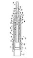
ファスナー154は、ファスナー154のマンドレル152をスリーブ108の開口部120に挿入することによって、引き込みヘッド100内に配置される。ジョー136は、スプリング負荷を受けてコレット128のテーパ部140内に座する。ジョー136によってこの位置に形成される内部形状は、マンドレル152が入ることを可能にするほど大きくはない。図12は、マンドレル152を受け入れるにほぼ十分となるようにジョー136が開く点までジョー136を押し戻した後のマンドレル152を示している。
The
マンドレル152は、図13に示されるように、ファスナー154のシフトワッシャ184がスリーブ108上に座するまでファスナー154が挿入されるときに、スプリング170によって与えられるスプリング負荷に抗してジョー136を開く。ジョー136は、それらが開くときに、スリーブ108内を後退し、それらの鋸歯状部146はマンドレル152の鋸歯状部150と整列する。フォロワースプリング170は縮み、そしてジョー136はジョーフォロワー162を押し戻すが、ジョーフォロワー162はスプリング保持部172とは接触しない。重スプリング174は、その前負荷を与えられた状態の長さから縮まない。
The
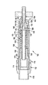
工具のトリガが押し込まれるときに、工具のヘッドピストンに取り付けられた内部サブアセンブリ(即ち、コレット128,引っ張り棒アダプタ130等)は、負荷を受けて後退する。図14は、マンドレル152が折れる寸前の中間ストローク位置にある引き込みヘッド100を示している。ヘッドピストンおよびコレット/引っ張り棒アダプタの移動は、工具のストロークとして知られており、例えば9/16”である。マンドレル152が破壊切り込みで折れるときに、ファスナー154は設置される。マンドレル152の残部は、ジョー136によって保持されたままである。
As the tool trigger is pushed, the internal subassemblies (ie,
マンドレル152が折れるときに、解放されたエネルギは、ジョー136とジョーフォロワー162を後退させ、スプリング保持部172に接触させる。スプリング保持部172のカップ形状故に、フォロワースプリング170は予め設定された安全な長さに圧縮されるだけであり、「あさり(set)」や失敗を起こさない。図15は、コレット128のテーパ部140との接触を断って、ジョーフォロワー162およびスプリング保持部172と共に1つのユニットとして移動するジョー136を示している。この移動は、ショックアブソーバーとして作用する重スプリング174による抵抗を受ける。
When the
工具のトリガが解放されるときに、ヘッドピストンおよび内部サブアセンブリは、それらのホームポジションに戻る。折れたマンドレル152は、(スプリング170によって与えられる)スプリング負荷を受けて依然としてジョー136で保持されている。マンドレル152は、図16に示されるように、しばしばスリーブ108から突出する。次のファスナーが挿入されるときに、そのマンドレルは、前のファスナーの折れたマンドレルを、ジョー136を通して押さなければならない。そのマンドレルは、ジョーフォロワー162のチューブ部分188に押し込まれて、ついにはヘッドピストンを通して設置工具の背面から押し出される。
When the tool trigger is released, the head piston and internal subassembly return to their home positions. The folded
図18は、図11〜16に示された引き込みヘッドの分解斜視図である。引き込みヘッド100が異なるスプリングレートの2つのスプリング170,174を有するという事実は、引き込みヘッド100が幅広いマンドレル径に関連して使用され得るようにする共に、引き込みヘッド100が高い慣性負荷を適応できるようにする。更には、引き込みヘッド100は、ノーズピースを有しないことが好ましい。しかも、引き込みヘッドは、非常に短いステムのファスナーが引き込みヘッド100を使用して設置され得るように、構成されることが好ましい。
FIG. 18 is an exploded perspective view of the retracting head shown in FIGS. The fact that the retracting
本発明の実施形態が図示され説明されたが、開示の精神及び範囲を逸脱すること無しに、当業者が本発明の種々の変形例を工夫することは想像される。 While embodiments of the invention have been illustrated and described, it is envisioned that those skilled in the art will devise various variations of the invention without departing from the spirit and scope of the disclosure.
100:引き込みヘッド
106:本体
108:スリーブ
112:スリーブアダプタ
116:ジャムナット
128:コレット
130:引っ張り棒アダプタ
136:ジョー
152:マンドレル
154:ファスナーまたはブラインドボルト
162:ジョーフォロワー
170:第2のスプリング(フォロワースプリング)
172:スプリング保持部
174:第1のスプリング
176:肩部
100: Retraction head 106: Body 108: Sleeve 112: Sleeve adapter 116: Jam nut 128: Collet 130: Pull rod adapter 136: Jaw 152: Mandrel 154: Fastener or blind bolt 162: Jaw follower 170: Second spring (follower) spring)
172: Spring holding portion 174: First spring 176: Shoulder portion
Claims (14)
Applications Claiming Priority (1)
| Application Number | Priority Date | Filing Date | Title |
|---|---|---|---|
| US58221004P | 2004-06-22 | 2004-06-22 |
Publications (2)
| Publication Number | Publication Date |
|---|---|
| JP2006007323A true JP2006007323A (en) | 2006-01-12 |
| JP2006007323A5 JP2006007323A5 (en) | 2006-12-07 |
Family
ID=34941699
Family Applications (1)
| Application Number | Title | Priority Date | Filing Date |
|---|---|---|---|
| JP2005176150A Pending JP2006007323A (en) | 2004-06-22 | 2005-06-16 | Tool for setting blind bolt |
Country Status (8)
| Country | Link |
|---|---|
| US (2) | US7366816B2 (en) |
| EP (1) | EP1609546A1 (en) |
| JP (1) | JP2006007323A (en) |
| KR (1) | KR100731710B1 (en) |
| CN (1) | CN1712191A (en) |
| BR (1) | BRPI0502530A (en) |
| CA (1) | CA2509001A1 (en) |
| TW (1) | TW200615059A (en) |
Cited By (3)
| Publication number | Priority date | Publication date | Assignee | Title |
|---|---|---|---|---|
| JP2010505629A (en) * | 2006-10-03 | 2010-02-25 | アブデル ユーケー リミテッド | Riveting tool |
| CN104122933A (en) * | 2014-06-30 | 2014-10-29 | 北京航天发射技术研究所 | Visualized locking mechanism |
| JP2018524177A (en) * | 2015-06-03 | 2018-08-30 | ダイムラー・アクチェンゲゼルシャフトDaimler AG | Method and joining element for joining at least two parts using a flow molded rivet sleeve |
Families Citing this family (22)
| Publication number | Priority date | Publication date | Assignee | Title |
|---|---|---|---|---|
| TW200506733A (en) * | 2003-08-15 | 2005-02-16 | Via Tech Inc | Apparatus and method for the co-simulation of CPU and DUT modules |
| WO2007084700A2 (en) * | 2006-01-19 | 2007-07-26 | University Of Maryland Office Of Technology Commercialization | System and method for thread handling in multithreaded parallel computing of nested threads |
| US8250394B2 (en) * | 2006-03-31 | 2012-08-21 | Stmicroelectronics International N.V. | Varying the number of generated clock signals and selecting a clock signal in response to a change in memory fill level |
| US8264610B2 (en) * | 2006-04-18 | 2012-09-11 | Marvell World Trade Ltd. | Shared memory multi video channel display apparatus and methods |
| US8218091B2 (en) * | 2006-04-18 | 2012-07-10 | Marvell World Trade Ltd. | Shared memory multi video channel display apparatus and methods |
| US8284322B2 (en) * | 2006-04-18 | 2012-10-09 | Marvell World Trade Ltd. | Shared memory multi video channel display apparatus and methods |
| US7536490B2 (en) * | 2006-07-20 | 2009-05-19 | Via Technologies, Inc. | Method for link bandwidth management |
| KR100805836B1 (en) * | 2006-07-26 | 2008-02-21 | 삼성전자주식회사 | Bus width configuration device, display device, and the method configuring bus width |
| US8449234B2 (en) * | 2007-01-16 | 2013-05-28 | Harry E. Taylor | Blind rivet |
| JP4753895B2 (en) * | 2007-02-20 | 2011-08-24 | ルネサスエレクトロニクス株式会社 | Array type processor having delay adjustment circuit |
| US8904408B1 (en) * | 2007-03-15 | 2014-12-02 | Intel Corporation | Pre-fetching data and overlapping data transfers in a HWA-DWA system |
| BR112012019153A2 (en) * | 2010-02-01 | 2017-07-11 | Alcoa Inc | nose set for fastener installation tool |
| DE102010024610B4 (en) * | 2010-06-22 | 2012-02-16 | Gesipa Blindniettechnik Gmbh | Setting tool with a variable setting stroke adjustment |
| GB2505901A (en) * | 2012-09-13 | 2014-03-19 | Infastech Ip Pte Ltd | Lockbolt |
| US9543728B2 (en) * | 2014-11-26 | 2017-01-10 | Pem Management, Inc. | Ring tongue clamping die |
| US9819560B2 (en) * | 2014-12-24 | 2017-11-14 | Mediatek Inc. | Dynamic data distribution method in private network and associated electronic device |
| CN106475956B (en) * | 2016-11-18 | 2018-05-08 | 安徽江淮汽车集团股份有限公司 | Valve collet pressure head |
| CN107052738B (en) * | 2017-02-04 | 2019-03-29 | 台州知管通科技有限公司 | A kind of clamping head applied on compression bar detaching equipment |
| US11238557B2 (en) * | 2019-03-29 | 2022-02-01 | Intel Corporation | Workload-based maximum current |
| US11148188B2 (en) * | 2019-10-28 | 2021-10-19 | The Boeing Company | Tool and associated method for installing a blind fastener |
| KR102135675B1 (en) * | 2020-03-24 | 2020-07-20 | (주)에이패스 | Fastening unit of blind bolt |
| KR102183421B1 (en) * | 2020-06-24 | 2020-11-26 | (주)에이패스 | Fastening unit of blind bolt |
Family Cites Families (31)
| Publication number | Priority date | Publication date | Assignee | Title |
|---|---|---|---|---|
| US3100578A (en) * | 1961-04-24 | 1963-08-13 | Milton A Halverson | Rivet guns |
| FR1292085A (en) | 1961-06-13 | 1962-04-27 | Mechanical riveting machine for hollow rivets for box riveting | |
| BE646128A (en) * | 1963-04-05 | |||
| US3324700A (en) | 1964-09-21 | 1967-06-13 | United Shoe Machinery Corp | Pulling chuck for rivet setting tool |
| US3406557A (en) | 1966-08-31 | 1968-10-22 | Olin Mathieson | Rivet tool |
| US3646800A (en) | 1970-02-12 | 1972-03-07 | Alan Martin | Mandrel rivet-setting tool |
| US3760627A (en) * | 1971-12-13 | 1973-09-25 | Richline Co Inc | Rivet gun |
| US4432679A (en) | 1977-09-21 | 1984-02-21 | Huck Manufacturing Company | Lock spindle blind fastener for single action application |
| US4844673A (en) | 1982-06-29 | 1989-07-04 | Huck Manufacturing Company | Lock spindle blind bolt with lock collar providing pin stop support |
| US4520648A (en) * | 1984-02-01 | 1985-06-04 | Gregory Tool Systems, Inc. | Lever operated riveter |
| US4653308A (en) * | 1985-11-06 | 1987-03-31 | The Gregory Company | Adjustable lever operated riveter |
| JP2522392B2 (en) * | 1988-08-05 | 1996-08-07 | 三菱電機株式会社 | Cyclic data transmission method |
| JP2969782B2 (en) * | 1990-05-09 | 1999-11-02 | ソニー株式会社 | Encoded data editing method and encoded data editing device |
| NO300834B1 (en) * | 1990-05-10 | 1997-08-04 | Wuerth Adolf Gmbh & Co Kg | Nagle device |
| US5802691A (en) * | 1994-01-11 | 1998-09-08 | Zoltaszek; Zenon | Rotary driven linear actuator |
| US5357666A (en) * | 1993-11-18 | 1994-10-25 | Textron Inc. | Fastener installation tool head quick disconnect assembly |
| US5809538A (en) | 1996-02-07 | 1998-09-15 | General Instrument Corporation | DRAM arbiter for video decoder |
| ES2144906B1 (en) * | 1996-09-03 | 2001-02-01 | Perez Aniento Andres | UNIVERSAL SIMPLIFIED RIVER. |
| US6012109A (en) | 1997-09-09 | 2000-01-04 | National Instruments Corporation | Video capture device with adjustable frame rate based on available bus bandwidth |
| US6105086A (en) * | 1998-06-04 | 2000-08-15 | Lsi Logic Corporation | Data communication circuit and method for buffering data between a shared resource and multiple interfaces |
| JP2000092375A (en) | 1998-07-17 | 2000-03-31 | Sony Corp | Signal processing unit and its control method |
| US6366325B1 (en) | 1998-12-07 | 2002-04-02 | Ati International Srl | Single port video capture circuit and method |
| US6720968B1 (en) | 1998-12-11 | 2004-04-13 | National Instruments Corporation | Video acquisition system including a virtual dual ported memory with adaptive bandwidth allocation |
| US6563506B1 (en) | 1998-12-14 | 2003-05-13 | Ati International Srl | Method and apparatus for memory bandwith allocation and control in a video graphics system |
| US6330647B1 (en) | 1999-08-31 | 2001-12-11 | Micron Technology, Inc. | Memory bandwidth allocation based on access count priority scheme |
| JP2001156807A (en) * | 1999-09-14 | 2001-06-08 | Sony Corp | Method, system, and device for transmission |
| US6662278B1 (en) | 2000-09-22 | 2003-12-09 | Intel Corporation | Adaptive throttling of memory acceses, such as throttling RDRAM accesses in a real-time system |
| US20040022094A1 (en) * | 2002-02-25 | 2004-02-05 | Sivakumar Radhakrishnan | Cache usage for concurrent multiple streams |
| JP2003258805A (en) * | 2002-02-28 | 2003-09-12 | Toshiba Corp | Buffer controller and buffer controlling method |
| US6934798B2 (en) | 2002-12-30 | 2005-08-23 | Micron Technology, Inc. | CAM with policy based bandwidth allocation |
| US20040263427A1 (en) * | 2003-06-25 | 2004-12-30 | Horigan John W. | Lossless clock domain translation for a pixel stream |
-
2005
- 2005-06-01 CA CA002509001A patent/CA2509001A1/en not_active Abandoned
- 2005-06-06 TW TW094118608A patent/TW200615059A/en unknown
- 2005-06-07 US US11/146,506 patent/US7366816B2/en active Active
- 2005-06-07 US US11/146,588 patent/US7263753B2/en not_active Expired - Fee Related
- 2005-06-15 EP EP05253720A patent/EP1609546A1/en not_active Withdrawn
- 2005-06-16 JP JP2005176150A patent/JP2006007323A/en active Pending
- 2005-06-17 BR BR0502530-3A patent/BRPI0502530A/en not_active Application Discontinuation
- 2005-06-21 CN CNA2005100790519A patent/CN1712191A/en active Pending
- 2005-06-21 KR KR1020050053275A patent/KR100731710B1/en not_active IP Right Cessation
Cited By (5)
| Publication number | Priority date | Publication date | Assignee | Title |
|---|---|---|---|---|
| JP2010505629A (en) * | 2006-10-03 | 2010-02-25 | アブデル ユーケー リミテッド | Riveting tool |
| CN104122933A (en) * | 2014-06-30 | 2014-10-29 | 北京航天发射技术研究所 | Visualized locking mechanism |
| CN104122933B (en) * | 2014-06-30 | 2016-06-22 | 北京航天发射技术研究所 | Visualization retaining mechanism |
| JP2018524177A (en) * | 2015-06-03 | 2018-08-30 | ダイムラー・アクチェンゲゼルシャフトDaimler AG | Method and joining element for joining at least two parts using a flow molded rivet sleeve |
| US10751788B2 (en) | 2015-06-03 | 2020-08-25 | WS Wieländer + Schill Professionelle Karosserie-Spezialwerkzeuge GmbH & Co. KG | Method and joining element for joining at least two components by means of a flow-formed rivet sleeve |
Also Published As
| Publication number | Publication date |
|---|---|
| US20050278918A1 (en) | 2005-12-22 |
| TW200615059A (en) | 2006-05-16 |
| US20050283634A1 (en) | 2005-12-22 |
| US7263753B2 (en) | 2007-09-04 |
| KR20060048445A (en) | 2006-05-18 |
| CN1712191A (en) | 2005-12-28 |
| BRPI0502530A (en) | 2006-02-07 |
| KR100731710B1 (en) | 2007-06-25 |
| CA2509001A1 (en) | 2005-12-22 |
| EP1609546A1 (en) | 2005-12-28 |
| US7366816B2 (en) | 2008-04-29 |
Similar Documents
| Publication | Publication Date | Title |
|---|---|---|
| JP2006007323A (en) | Tool for setting blind bolt | |
| US3906776A (en) | Self-drilling blind riveting tool | |
| US20100275424A1 (en) | Blind Rivet Fastening Device | |
| US7467451B2 (en) | Offset pulling head | |
| JP2006130567A (en) | Self-matching type tool for setting drawing-in type fastening tool | |
| TWI572425B (en) | A blind rivet fastening device and floating piece | |
| US3196662A (en) | Pulling head device for the stem of fasteners | |
| TWI574773B (en) | Collet chuck, chuck apparatus, and method for manufacturing worked products | |
| US7698794B2 (en) | Load control mechanism for pull type tools | |
| AU774518B2 (en) | Riveting tool | |
| US5598619A (en) | Hydraulic installation tool | |
| JP2006513040A (en) | Nut plate riveter | |
| JPH06154935A (en) | Tool for rivet setting | |
| JP2006187787A (en) | Fastening device for blind rivet | |
| US3616673A (en) | Combination rotating and reciprocating rivet tool | |
| JP2013518722A (en) | Nose assembly for fastener mounting tool | |
| JP2006520691A5 (en) | ||
| US11292050B1 (en) | Hydraulic fastener tool | |
| US20020157226A1 (en) | Device for handling retaining ring bolts | |
| JP2006520691A (en) | Offset nose assembly with improved deflector and protection assembly | |
| US4958510A (en) | Fastener installation apparatus | |
| US2455903A (en) | Dimpling mandrel | |
| US20220341461A1 (en) | Retention device | |
| JP3481998B2 (en) | Fastening tool | |
| US11697148B1 (en) | Hydraulic fastener tool |
Legal Events
| Date | Code | Title | Description |
|---|---|---|---|
| A521 | Written amendment |
Free format text: JAPANESE INTERMEDIATE CODE: A523 Effective date: 20061020 |