JP2005537535A - System for generating a 3D electronic model of an object - Google Patents
System for generating a 3D electronic model of an object Download PDFInfo
- Publication number
- JP2005537535A JP2005537535A JP2004519656A JP2004519656A JP2005537535A JP 2005537535 A JP2005537535 A JP 2005537535A JP 2004519656 A JP2004519656 A JP 2004519656A JP 2004519656 A JP2004519656 A JP 2004519656A JP 2005537535 A JP2005537535 A JP 2005537535A
- Authority
- JP
- Japan
- Prior art keywords
- dimensional electronic
- texture
- scanner
- image
- generation system
- Prior art date
- Legal status (The legal status is an assumption and is not a legal conclusion. Google has not performed a legal analysis and makes no representation as to the accuracy of the status listed.)
- Pending
Links
Images


Classifications
-
- G—PHYSICS
- G01—MEASURING; TESTING
- G01C—MEASURING DISTANCES, LEVELS OR BEARINGS; SURVEYING; NAVIGATION; GYROSCOPIC INSTRUMENTS; PHOTOGRAMMETRY OR VIDEOGRAMMETRY
- G01C15/00—Surveying instruments or accessories not provided for in groups G01C1/00 - G01C13/00
- G01C15/002—Active optical surveying means
-
- G—PHYSICS
- G01—MEASURING; TESTING
- G01C—MEASURING DISTANCES, LEVELS OR BEARINGS; SURVEYING; NAVIGATION; GYROSCOPIC INSTRUMENTS; PHOTOGRAMMETRY OR VIDEOGRAMMETRY
- G01C15/00—Surveying instruments or accessories not provided for in groups G01C1/00 - G01C13/00
-
- G—PHYSICS
- G01—MEASURING; TESTING
- G01S—RADIO DIRECTION-FINDING; RADIO NAVIGATION; DETERMINING DISTANCE OR VELOCITY BY USE OF RADIO WAVES; LOCATING OR PRESENCE-DETECTING BY USE OF THE REFLECTION OR RERADIATION OF RADIO WAVES; ANALOGOUS ARRANGEMENTS USING OTHER WAVES
- G01S17/00—Systems using the reflection or reradiation of electromagnetic waves other than radio waves, e.g. lidar systems
- G01S17/86—Combinations of lidar systems with systems other than lidar, radar or sonar, e.g. with direction finders
-
- G—PHYSICS
- G01—MEASURING; TESTING
- G01S—RADIO DIRECTION-FINDING; RADIO NAVIGATION; DETERMINING DISTANCE OR VELOCITY BY USE OF RADIO WAVES; LOCATING OR PRESENCE-DETECTING BY USE OF THE REFLECTION OR RERADIATION OF RADIO WAVES; ANALOGOUS ARRANGEMENTS USING OTHER WAVES
- G01S17/00—Systems using the reflection or reradiation of electromagnetic waves other than radio waves, e.g. lidar systems
- G01S17/88—Lidar systems specially adapted for specific applications
- G01S17/89—Lidar systems specially adapted for specific applications for mapping or imaging
-
- G—PHYSICS
- G06—COMPUTING; CALCULATING OR COUNTING
- G06F—ELECTRIC DIGITAL DATA PROCESSING
- G06F18/00—Pattern recognition
-
- G—PHYSICS
- G06—COMPUTING; CALCULATING OR COUNTING
- G06T—IMAGE DATA PROCESSING OR GENERATION, IN GENERAL
- G06T11/00—2D [Two Dimensional] image generation
- G06T11/001—Texturing; Colouring; Generation of texture or colour
-
- G—PHYSICS
- G06—COMPUTING; CALCULATING OR COUNTING
- G06T—IMAGE DATA PROCESSING OR GENERATION, IN GENERAL
- G06T15/00—3D [Three Dimensional] image rendering
- G06T15/04—Texture mapping
-
- G—PHYSICS
- G06—COMPUTING; CALCULATING OR COUNTING
- G06T—IMAGE DATA PROCESSING OR GENERATION, IN GENERAL
- G06T17/00—Three dimensional [3D] modelling, e.g. data description of 3D objects
-
- G—PHYSICS
- G06—COMPUTING; CALCULATING OR COUNTING
- G06T—IMAGE DATA PROCESSING OR GENERATION, IN GENERAL
- G06T17/00—Three dimensional [3D] modelling, e.g. data description of 3D objects
- G06T17/05—Geographic models
-
- G—PHYSICS
- G06—COMPUTING; CALCULATING OR COUNTING
- G06T—IMAGE DATA PROCESSING OR GENERATION, IN GENERAL
- G06T17/00—Three dimensional [3D] modelling, e.g. data description of 3D objects
- G06T17/10—Constructive solid geometry [CSG] using solid primitives, e.g. cylinders, cubes
-
- G—PHYSICS
- G06—COMPUTING; CALCULATING OR COUNTING
- G06T—IMAGE DATA PROCESSING OR GENERATION, IN GENERAL
- G06T7/00—Image analysis
- G06T7/30—Determination of transform parameters for the alignment of images, i.e. image registration
-
- G—PHYSICS
- G06—COMPUTING; CALCULATING OR COUNTING
- G06T—IMAGE DATA PROCESSING OR GENERATION, IN GENERAL
- G06T7/00—Image analysis
- G06T7/50—Depth or shape recovery
- G06T7/55—Depth or shape recovery from multiple images
- G06T7/593—Depth or shape recovery from multiple images from stereo images
-
- G—PHYSICS
- G01—MEASURING; TESTING
- G01S—RADIO DIRECTION-FINDING; RADIO NAVIGATION; DETERMINING DISTANCE OR VELOCITY BY USE OF RADIO WAVES; LOCATING OR PRESENCE-DETECTING BY USE OF THE REFLECTION OR RERADIATION OF RADIO WAVES; ANALOGOUS ARRANGEMENTS USING OTHER WAVES
- G01S19/00—Satellite radio beacon positioning systems; Determining position, velocity or attitude using signals transmitted by such systems
- G01S19/01—Satellite radio beacon positioning systems transmitting time-stamped messages, e.g. GPS [Global Positioning System], GLONASS [Global Orbiting Navigation Satellite System] or GALILEO
- G01S19/13—Receivers
- G01S19/14—Receivers specially adapted for specific applications
-
- G—PHYSICS
- G01—MEASURING; TESTING
- G01S—RADIO DIRECTION-FINDING; RADIO NAVIGATION; DETERMINING DISTANCE OR VELOCITY BY USE OF RADIO WAVES; LOCATING OR PRESENCE-DETECTING BY USE OF THE REFLECTION OR RERADIATION OF RADIO WAVES; ANALOGOUS ARRANGEMENTS USING OTHER WAVES
- G01S19/00—Satellite radio beacon positioning systems; Determining position, velocity or attitude using signals transmitted by such systems
- G01S19/38—Determining a navigation solution using signals transmitted by a satellite radio beacon positioning system
- G01S19/39—Determining a navigation solution using signals transmitted by a satellite radio beacon positioning system the satellite radio beacon positioning system transmitting time-stamped messages, e.g. GPS [Global Positioning System], GLONASS [Global Orbiting Navigation Satellite System] or GALILEO
- G01S19/40—Correcting position, velocity or attitude
- G01S19/41—Differential correction, e.g. DGPS [differential GPS]
Landscapes
- Engineering & Computer Science (AREA)
- Physics & Mathematics (AREA)
- General Physics & Mathematics (AREA)
- Theoretical Computer Science (AREA)
- Remote Sensing (AREA)
- Radar, Positioning & Navigation (AREA)
- Geometry (AREA)
- Computer Graphics (AREA)
- Software Systems (AREA)
- Computer Networks & Wireless Communication (AREA)
- Electromagnetism (AREA)
- Computer Vision & Pattern Recognition (AREA)
- Life Sciences & Earth Sciences (AREA)
- Artificial Intelligence (AREA)
- Bioinformatics & Cheminformatics (AREA)
- Bioinformatics & Computational Biology (AREA)
- Data Mining & Analysis (AREA)
- Evolutionary Biology (AREA)
- Evolutionary Computation (AREA)
- General Engineering & Computer Science (AREA)
- Processing Or Creating Images (AREA)
- Image Generation (AREA)
- Instructional Devices (AREA)
- Length Measuring Devices By Optical Means (AREA)
- Image Processing (AREA)
Abstract
オブジェクトの3次元電子モデルを開発する画像生成システム(100)は、スキャナ(104)と計算システム(102)とを含む。スキャナは、異なる地理的位置内のオブジェクトに隣接して選択的に位置決めされ得る。スキャナは、スキャナ位置情報およびオブジェクトを表す画像データを計算システムに提供し得る。計算システムは、画像データおよびスキャナ位置情報からオブジェクトの3次元電子モデルを生成し得る。3次元電子モデルは記憶され、他の応用、例えば電子ナビゲーションマップに利用され得る。An image generation system (100) for developing a three-dimensional electronic model of an object includes a scanner (104) and a computing system (102). The scanner can be selectively positioned adjacent to objects in different geographic locations. The scanner may provide scanner position information and image data representing the object to the computing system. The computing system can generate a three-dimensional electronic model of the object from the image data and scanner position information. The three-dimensional electronic model can be stored and used for other applications, such as electronic navigation maps.
Description
(優先権の主張)
本願は米国仮出願第60/395,165号(2002年7月10日出願)の利益を請求するものである。上記出願の開示は本願明細書で参照により援用される。
(Claiming priority)
This application claims the benefit of US Provisional Application No. 60 / 395,165 (filed Jul. 10, 2002). The disclosure of the above application is incorporated herein by reference.
1.著作権の保護に関する告知
本開示の一部には著作権の保護の対象となる事項が含まれている。本著作権所有者は、特許商標庁の特許ファイルや記録の形で生じるような、本開示の何人が行うファクシミリでの複製に対しても反対するものではない。但し、それ以外についてはすべての著作権を保有するものである。
1. Copyright protection notice Part of this disclosure includes items that are subject to copyright protection. The copyright owner is not opposed to facsimile duplication by any person of the present disclosure as may occur in the form of a patent file or record of the Patent and Trademark Office. However, all other copyrights are reserved.
2.技術分野
本発明は一般にオブジェクトの電子表示物に関し、特に、電子形式で表される3次元オブジェクトのモデルを生成するためのシステムに関する。
2. TECHNICAL FIELD The present invention relates generally to electronic representations of objects, and more particularly to a system for generating a model of a three-dimensional object represented in electronic form.
(発明の背景)
3.関連する技術
ナビゲーションマップは電子形式で表示することが可能である。ナビゲーションマップのなかには2次元で電子的に表示されるものもある。そのため、ナビゲーションマップのユーザは、ディスプレイ上のある場所へ向けて自分を方向づける際に困難を感じる場合がある。3次元でオブジェクトを表示しているナビゲーションマップは、ユーザが周囲の状況の中にいて観察するようにオブジェクトの表示を行うことにより、上記欠点の解決を図ることが可能となる。
(Background of the Invention)
3. Related Technology Navigation maps can be displayed in electronic form. Some navigation maps are electronically displayed in two dimensions. Therefore, navigation map users may find it difficult to orient themselves toward a certain location on the display. The navigation map displaying objects in three dimensions can solve the above-mentioned drawbacks by displaying the objects so that the user can observe them in the surrounding environment.
オブジェクトの3次元の電子表示物はデジタルカメラを用いて作成したものであってもよい。アーティストたちは別の技法を使ってオブジェクトの3次元表示を手で作成する。さらに別の技法ではレーザが用いられる。レーザ技術を利用して、オブジェクトからレーザ光を反射して距離の測定が行われる。これらの距離を用いてオブジェクトの形状のマップ化が行われ、電子表示物の形成が可能となる。現行のレーザ技術では、距離は、オブジェクト上にインストールする必要がある金属性ターゲットなどの基準点から測定される。したがって、これらのターゲットはオブジェクトのマルチ走査の中に含まれるものであってもよい。マルチ走査時に、ターゲットを用いて手動による合成を行って3次元表示に変えるようにしてもよい。公知のレーザ技術はオブジェクトの幾何学的形状を生成するにすぎない。 The three-dimensional electronic display object may be created using a digital camera. Artists use a different technique to manually create a three-dimensional representation of an object. Yet another technique uses a laser. Laser technology is used to measure distance by reflecting laser light from an object. Using these distances, the object shape is mapped, and an electronic display object can be formed. In current laser technology, distance is measured from a reference point such as a metallic target that needs to be installed on the object. Thus, these targets may be included in multiple scans of the object. At the time of multi-scanning, manual synthesis using a target may be performed to change to three-dimensional display. Known laser techniques only generate object geometry.
電子ナビゲーションマップでは、複雑なオフィスやショッピングモールなどのような、大きなマルチ構造のオブジェクトの精密な電子表示物によって、自分がいる周囲の位置を認識することが可能となる。ユーザが、観察した周囲の状況と表示オブジェクトとを精密に比較するために、視覚的詳細情報と、大きなオブジェクトのその他の特徴とを必要とする場合もある。不都合なことに、デジタルカメラを用いた電子表示物は、十分な視覚的詳細および特徴を提供できないマルチプル電子画像を手動で合成することを要求する。アーティストによって手動で作成された電子表示物は、不正確であり、時間を消費し、コストがかかり、また不必要にかなりのデータを電子ナビゲーションマップに追加し得る。さらに、レーザを用いた電子表示物は、オブジェクトを走査中にインストールおよび/または維持することの困難な、オブジェクト上の参照点を要求する。そのため、大きなオブジェクトを表す電子モデルを正確かつ効率的に作成することに関連する技術的な問題が存在する。さらに、マルチプル走査の各々をオブジェクトを表す電子モデルに変換する技術に関連する技術的な問題が存在する。 In the electronic navigation map, it is possible to recognize the position of the surrounding area by a precise electronic display object of a large multi-structure object such as a complex office or a shopping mall. The user may need visual details and other features of the large object to accurately compare the observed surroundings with the display object. Unfortunately, electronic displays using digital cameras require manual synthesis of multiple electronic images that cannot provide sufficient visual details and features. Electronic displays manually created by artists are inaccurate, time consuming, costly, and can add unnecessarily significant data to an electronic navigation map. Furthermore, electronic displays using lasers require a reference point on the object that is difficult to install and / or maintain during scanning. Therefore, there are technical problems associated with accurately and efficiently creating an electronic model that represents a large object. In addition, there are technical problems associated with the technique of converting each of the multiple scans into an electronic model representing the object.
したがって、ナビゲーションマップや、従来技術の欠点を解決するその他のシステムで使用する3次元オブジェクトの電子表示物を生成するためのシステムに対する要望が存在する。 Accordingly, there is a need for a system for generating electronic representations of three-dimensional objects for use in navigation maps and other systems that overcome the shortcomings of the prior art.
(要約)
本発明は、電子モデルにおける3次元オブジェクトの電子表示物を生成できる画像生成システムを提供する。オブジェクトの3次元電子モデルは、ナビゲーションマップといった用途に利用され得る。このようなオブジェクトは、例えば、事務所の建物、病院、住宅、橋、像、植生、および/また、他の自然もしくは人工のランドマークを含み得る。
(wrap up)
The present invention provides an image generation system capable of generating an electronic display object of a three-dimensional object in an electronic model. The three-dimensional electronic model of the object can be used for applications such as a navigation map. Such objects may include, for example, office buildings, hospitals, houses, bridges, statues, vegetation, and / or other natural or artificial landmarks.
画像生成システムは、スキャナ、計算システムを含む。スキャナは、別々の走査を実行するオブジェクトの周りの異なる地理的位置に位置し得る。走査の各々の間に収集されたデータは、計算システムに提供され得る。走査データを用いて、計算システムは、3次元電子モデルを生成し得る。3次元電子モデルは、オブジェクトを視覚的に表す縮尺され、色付けされ、テクスチャライズされたモデルであり得る。 The image generation system includes a scanner and a calculation system. The scanner may be located at different geographic locations around the object performing separate scans. Data collected during each of the scans can be provided to the computing system. Using the scan data, the computing system can generate a three-dimensional electronic model. A three-dimensional electronic model can be a scaled, colored, and textured model that visually represents an object.
スキャナは、ポイントスキャナ、カラースキャナ、および位置システムを含み得る。ポイントスキャナは、オブジェクトの幾何学的形状を表す幾何学的な点を決定するために用いられ得る。カラースキャナは、ポイントスキャナと同期して動作することにより、オブジェクトのカラーを表す色点を決定し得る。位置システムは、ナビゲーション座標(例えば、緯度および経度)、スキャナの高さ、傾斜および方向の形で位置情報を決定し得る。 Scanners can include point scanners, color scanners, and position systems. Point scanners can be used to determine geometric points that represent the geometric shape of an object. The color scanner can determine a color point representing the color of the object by operating in synchronization with the point scanner. The position system may determine position information in the form of navigation coordinates (eg, latitude and longitude), scanner height, tilt, and direction.
各々のスキャナからの幾何学的な点は、色点、位置情報は、3次元電子画像を形成するように関連付けられ得る。3次元電子画像の各々内で、幾何学的な点は、表面もしくはラインを形成するために結合され得る。加えて、3次元電子画像は、3次元電子モデルを形成するために位置情報を用いる計算システムによって合成され得る。互いの3次元電子画像の変換および回転の操作は、合成処理中に実行され得る。従って、任意の形状および/または任意のサイズのオブジェクトは、走査され得て、個々のスキャンは、合成されることにより、オブジェクトの幾何学的形状である3次元電子モデルを形成する。 Geometric points from each scanner, color points, position information can be associated to form a three-dimensional electronic image. Within each of the three-dimensional electronic images, geometric points can be combined to form a surface or line. In addition, a three-dimensional electronic image can be synthesized by a computing system that uses position information to form a three-dimensional electronic model. The operations of transforming and rotating each other's three-dimensional electronic images can be performed during the compositing process. Thus, any shape and / or any size object can be scanned, and the individual scans are combined to form a three-dimensional electronic model that is the geometric shape of the object.
計算システムは、また3次元電子モデルの表面をテクスチャライズする。テクスチャライズ化は、オブジェクトの1つ以上の表面で視覚的感知されるフィーチャの電子表示物を3次元電子モデルに加えることを伴う。テクスチャライズする処理プロセスは、ソーステクスチャとしてオブジェクトの電子写真といったイメージファイルを識別することを伴う。ソーステクスチャは、一意の識別子を割り当てられて、ライブラリに保存され得る。加えて、ソーステクスチャは、1つ以上の3次元電子モデルに関連付けられ得る。さらに、ソーステクスチャは、複合テクスチャを形成するために用いられ得る。 The computing system also textures the surface of the 3D electronic model. Texturization involves adding an electronic representation of features visually sensed on one or more surfaces of an object to a three-dimensional electronic model. The texturing process involves identifying an image file, such as an electronic photo of the object, as the source texture. Source textures can be assigned a unique identifier and stored in a library. In addition, the source texture can be associated with one or more three-dimensional electronic models. Further, the source texture can be used to form a composite texture.
ソーステクチャは、少なくともソーステクスチャの一部を形成するために変換され得る。ソーステクスチャの変換は、ソーステクスチャの一意の識別子を含む変換処理手順を創作することを伴う。変換処理手順は、3次元電子モデルの1つ以上の表面に関連付けられ得る。3次元オブジェクトが表示されるとき、変換処理手順は、ソーステクスチャから複合テクスチャを生成するために実行され得る。従って、ソーステクスチャおよび変換処理手順だけが、3次元電子モデルの表面に関連付けされる必要がある。 The source texture can be converted to form at least a portion of the source texture. Source texture transformation involves creating a transformation procedure that includes a unique identifier of the source texture. The transformation procedure can be associated with one or more surfaces of the three-dimensional electronic model. When a three-dimensional object is displayed, a conversion procedure can be performed to generate a composite texture from the source texture. Therefore, only the source texture and transformation procedure need be associated with the surface of the 3D electronic model.
本発明のその他のシステム、方法、特徴および利点は、以下の図と詳細な説明をチェックするとき、当業者には明らかであり、明らかになる。この説明に含まれるすべての上記のような追加のシステム、方法、特徴および利点は本発明の範囲内に含まれ、さらに、以下の請求項によってこれらを保護しようとするものである。 Other systems, methods, features and advantages of the present invention will be apparent to and will be apparent to those skilled in the art upon review of the following figures and detailed description. All such additional systems, methods, features and advantages included in this description are included within the scope of the present invention and are intended to be protected by the following claims.
本発明は以下の図面と説明とを参照することにより良く理解することができる。図内の構成要素は必ずしも縮尺に合っているとはかぎらない。代わりに、本発明の原理の説明時に強調が行われている。さらに、図では、同じ参照番号は異なる図を通してずっと対応する部分を示すものとする。 The invention can be better understood with reference to the following drawings and description. The components in the figures are not necessarily to scale. Instead, emphasis is placed on explaining the principles of the present invention. Moreover, in the figures, like reference numerals designate corresponding parts throughout the different views.
(好ましい実施形態についての詳細な説明)
本発明は、オブジェクトを表すテクスチャライズされた3次元電子モデルの開発が可能な画像生成システムを提供するものである。電子モデルは、生成されるとすぐに、ナビゲーションマップを含む多くのアプリケーションで使用することができる。“電子表示物”、“電子形式”、“電子モデル”および“電子画像”という用語は、データファイルなどの、キャプチャされ、操作され、記憶され、視覚的に表示されるデジタルデータの任意の6つの形式を含むものと広く解釈することが望ましい。
(Detailed description of preferred embodiments)
The present invention provides an image generation system capable of developing a textured three-dimensional electronic model representing an object. As soon as the electronic model is generated, it can be used in many applications, including navigation maps. The terms “electronic display”, “electronic form”, “electronic model”, and “electronic image” refer to any six pieces of digital data that are captured, manipulated, stored, and visually displayed, such as data files. It should be interpreted broadly as including one form.
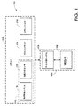
図1は画像生成システム100の一例を示すブロック図である。画像生成システム100はスキャナ104と通信する計算システム102を備える。計算システム102は、命令の実行、計算、データの記憶、データの検索、および、スキャナ104との通信の実行が可能な任意の装置であってもよい。
FIG. 1 is a block diagram illustrating an example of an
計算システム102は、ハンドヘルドコンピュータ、ラップトップコンピュータ、デスクトップ型コンピュータ、サーバコンピュータ、メインフレームなどの形で利用可能な特徴と、機能と、能力とを備えるものであってもよい。例えば、計算システム102は、少なくとも1つのプロセッサ、少なくとも一つのユーザインタフェース少なくとも1つのデータ記憶装置、少なくとも1つの通信用インタフェース、などを備えたものであってもよい。例示の計算システム102はサイト計算システム106と実験室計算システム108とを備えるものである。サイト計算システム106と実験室計算システム108との間での通信は、1または2以上のネットワークを介して無線通信路、有線通信路および/または光通信路を用いることもできる。上記とは別に、電子メモリデバイスなどのメモリ記憶装置を介してサイト計算システム106と実験室計算システム108との間でデータ転送を行うことも可能である。計算システム102とスキャナ104との間で同様の通信技術を利用することもできる。
The
2つの別個のシステムとして、サイト計算システムと実験室計算システム106と108を例示したが、単一の計算システムまたは3つまたはそれ以上の計算システムを用いることも可能である。さらに、サイト計算システム106および実験室計算システム108において、マルチスタンドアロン型の協働処理を行う計算システムを提示することも可能である。
Although two separate systems are illustrated, site computing system and
スキャナ104は、測位システム112、ポイントスキャナ114およびカラースキャナ116であってもよい。測位システム112はスキャナ104の物理的位置決めを行う任意のシステムであってもよい。スキャナ位置情報はスキャナ104の地理上の位置、勾配および向きを含むようにしてもよい。例示の測位システム112は衛星による測位システム120および勾配方向センサ122を備える。
The
衛星による測位システム120は三角測量技術による処理によって、スキャナ104の地理上の位置を決定する任意の測位システムであってもよい。例えば、測位システム112は、全地球測位システム(GPS)、ディファレンシャル全地球測位システム(DGPS)あるいは全地球軌道ナビゲーション衛星システム(GLONASS)であってもよい。地理上の位置はナビゲーション座標(緯度と経度など)で決定することも可能である。さらに、衛星による測位システム120によってスキャナ104の平均海面からの高度を決定することも可能である。
The
勾配方向センサ122は上記平均海面とスキャナ104の面方向の検出が可能な任意のセンサであってもよい。例えば、勾配方向センサ122は、磁針の北に基づいて北、南などのスキャナ104の面方向を示す電気信号を出力する少なくとも1つの電子センサを備えることも可能である。さらに、勾配方向センサ122は、例えば、重力に基づいてスキャナ104のピッチとロールを示す電気信号を出力するセンサを備えることも可能である。
The
ポイントスキャナ114は、オブジェクトの幾何学的3次元電子画像のポイントクラウド表示を展開するためにオブジェクトの測定が可能な任意の装置であってもよい。例えば、ポイントスキャナ114は、オブジェクト上の異なる点に選択的に向けられるレーザ光を備えるものであってもよい。反射されたレーザ光に基づいて、スキャナ104と点との間の距離を決定することも可能である。この距離を用いてオブジェクトの表面上の点を表す幾何学的な点データを生成することも可能である。レーザスキャナの一例として、オーストリアのRieglレーザ計測システムGmbH社により製造されたLMS−Zシリーズの地上用3Dスキャナがある。
ポイントスキャナ114に含まれるプロセッサはポイントクラウドを形成する幾何学的な点を決定し、記録することも可能である。例えば、オブジェクト上の各々の点とスキャナ104との間の距離を用いてポイントクラウドを決定することも可能である。測定された距離に基づく点記録用ソフトウェアの例として、RiSCANソフトウェアがあり、このソフトウェアはオーストリアのRieglレーザ計測システムGmbH社から入手することができる。
The processor included in the
カラースキャナ116はオブジェクトの色を表すパラメータを検知することが可能な任意の装置であってもよい。カラースキャナ116はオブジェクトに対して光ビームを選択的に指向することも可能である。オブジェクトからのビーム光の反射に基づいて、カラーパラメータを決定してもよい。検出されたパラメータは、ピクセルと呼ばれることもある色点であってもよい。ポイントスキャナ114内のプロセッサは色点を決定し、記録することも可能である。
The
ポイントスキャナ114を用いて収集された幾何学的な点の形での画像データはオブジェクトの幾何学的形状を表わすことができる。カラースキャナ116を用いて収集された色点(すなわちピクセル)の形の画像データはオブジェクトのカラーを表わすことが可能となる。本願明細書で使用されているように、“画像データ”という用語は幾何学的な点と色点との組み合わせを意味するものである。
Image data in the form of geometric points collected using the
ポイントスキャナ114とカラースキャナ116とは同期作動して画像データを収集する2つの独立した走査装置であってもよい。幾何学的な点は走査範囲内の色点と関連づけることも可能である。例えば、ポイントスキャナ114は、カラースキャナ116が出射したレーザ光から5センチメートル離れた光ビームを出射することができる。カラースキャナ116はオブジェクトの所定領域の範囲内のカラー“ライン”を走査するラインセンサであってもよい。個々のカラーラインは、カラースキャナ116によりオブジェクト上へ投影される所定の幅の縦に延伸された光ビームの幅と長さとによって画定される。例えば、カラーセンサは、所定の幅と高さの垂直方向または水平方向の矩形領域である所定領域の範囲内を走査することができる。この矩形領域は、矩形領域全体が完全に走査されてしまうまで、連続的に走査されるさらに狭い縦に延伸するカラー領域(カラーラインなど)に分割することも可能である。カラーラインの測定値は、色点を含む色点データの検出の結果得られる。
The
色点を検出する時間は幾何学的な点の検出時間よりも長くすることができる。したがって、走査中に、カラースキャナ116はラインセンサとして働いて、ある時間の間、オブジェクト上の所定領域内の色点(ピクセル)ラインを検出することができる。同じ時間中に、ポイントスキャナ114は同じ領域内の個々の幾何学的な点を検出することができる。次いで、計算システム102は所定領域で検出した色点ラインを同じ所定領域で検出した幾何学的な点と関連づけて、画像データを形成することができる。
The time for detecting a color point can be longer than the time for detecting a geometric point. Thus, during scanning, the
上記とは別に、カラースキャナ116は所定領域を走査して、所定数の色点を収集することができる。同時に、ポイントスキャナ114は同じ領域で所定数の幾何学的な点を検出することができる。カラースキャナ116による所定領域の走査のほうが長い時間をかけることができるため、より少数の色点がキャプチャされて、より多数の幾何学的な点との関連づけを行うことができる。後程論じるように、色点間の空隙を塗りつぶすこともできる。ポイントスキャナ114とカラースキャナ116の処理を同期させることにより、計算システム102はオブジェクトの走査画像をキャプチャすることができる。
Alternatively, the
動作中、ビルなどの走査対象オブジェクトに隣接する第1の地理上の位置にスキャナ104を配置することができる。“走査する”または“走査される”という用語は、スキャナ104の地理上の再配置を行うことなく所定時間中にスキャナ104が収集するオブジェクトおよび/またはスキャナ104と関連する任意のデータを含むものと広く解釈することが望ましい。“複数の走査”という用語は、データを収集するスキャナ104の異なる空間的位置を意味する。
In operation, the
走査中、スキャナ104のナビゲーション座標、勾配、および向きを測位システム112によって決定し、計算システム102へ出力することができる。ナビゲーション座標の決定は、走査中複数の異なる基準位置をとることも可能である。この基準位置を用いて平均基準位置を算出することができる。次いで、基準位置のナビゲーション座標を用いてスキャナ104の地理上の位置を記述することができる。
During the scan, the navigation coordinates, gradient, and orientation of the
さらに、ポイントスキャナ114はオブジェクトを走査し、ポイントクラウドの形で幾何学的な点データを生成することができる。同時に、カラースキャナ116はオブジェクトを走査し、色点データを生成することができる。幾何学的な点データと色点データとは画像データとして計算システム102により同期してキャプチャすることができる。したがって、計算システム102によって少なくとも1つの幾何学的な点を少なくとも1つの色点と関連づけることができる。
Furthermore, the
計算システム102は、衛星による測位システム120と勾配方向センサ122とにより出力されたデータを、ポイントスキャナ114とカラースキャナ116とによって出力された画像データと関連づけることができる。この走査の結果、幾何学的3次元カラー電子画像を展開することができる。スキャナ104の向き、勾配、地理上の位置をこの3次元電子画像と関連づけることができる。本願明細書で使用されているように、“3次元電子画像”という用語は、画像データ(幾何学的な点および/または色点)と、単一の走査中に収集された位置情報とに基づくオブジェクトの表示を意味するものである。第1の地理上の位置での走査の終了に続いて、第2の地理上の位置へスキャナ104を地理的に再配置し、走査処理を繰り返すことができる。
The
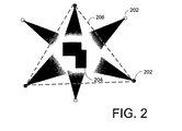
図2は、オブジェクト204の周辺のスキャナ104(図1)の複数の地理上の位置202を示す1例である。図示の例ではオブジェクト204はビルである。地理上の位置202(したがって異なる走査)の数は、走査中のオブジェクトの幾何学的形状に基づいて決定することができる。十分な走査を行うことにより、毎回の走査中にスキャナ104が収集した幾何学的な点データと色点データとのオーバーラップ部分が得られる。
FIG. 2 is an example showing a plurality of
図2で、三角形206上の点を表す3つの地理上の位置が走査対象位置として特定される。三角形206の範囲内にオブジェクト204の境界を完全に取り囲むように三角形206のサイズが定められる。オブジェクト204の形状および/または異なる表面に基づいて、3回の走査を行うことができる。しかし、オブジェクトの表面全体を精密にキャプチャするために追加の走査を必要とする場合もある。ポイントスキャナ114がレーザスキャナである場合、スキャナ104の視野方向内に存在しないオブジェクト204の表面領域は単なる3回の走査では表わすことができない場合がある。したがって、オブジェクトの種々の特徴の視野方向にスキャナ104の空間的位置決めを行ってもよく、さらに、追加走査の視野方向にスキャナ104の空間的位置決めを行ってもよい。
In FIG. 2, three geographical positions representing points on the
オブジェクトを表す3次元電子モデルの生成に必要な走査回数(3次元電子画像の数など)は、オブジェクトの対称性に基づいて最小限にとどめるようにしてもよい。オブジェクトの表面の走査を行う代わりに、左右対称部分を含むオブジェクトを電子的に再現するようにしてもよい。すなわち、オブジェクトの走査済みの部分が、オブジェクトの未走査部分に関して左右対称であれば、未走査部分の走査を回避することが可能となる。走査を行う代わりに、上記走査済みの部分を鏡映して、未走査部分を表わすようにすることができる。 The number of scans (such as the number of three-dimensional electronic images) necessary for generating a three-dimensional electronic model representing an object may be minimized based on the symmetry of the object. Instead of scanning the surface of the object, an object including a symmetrical part may be electronically reproduced. That is, if the scanned part of the object is symmetrical with respect to the unscanned part of the object, it is possible to avoid scanning the unscanned part. Instead of scanning, the scanned portion can be mirrored to represent the unscanned portion.
図3は、スキャナ104を用いて走査できるオブジェクトの種々の例を示す。第1のオブジェクト302は回転により左右対称オブジェクトである。回転により左右対称となる領域を持つオブジェクトの例には、テレビ塔、給水塔などを含めることができる。オブジェクトが回転により左右対称となる場合、2または3回以上の走査に基づいて3次元モデル化を行うことができる。第2のオブジェクト304は、4回またはそれ以上の回数の走査を用いて3次元電子モデル化を行うことができるような4つの左右対称領域を有するオブジェクトである。第3のオブジェクト306は軸線308に沿って左右対称である。したがって、軸線308の一方またはそれ以上の側部だけに沿って走査を行うことができる。
FIG. 3 shows various examples of objects that can be scanned using the
オブジェクトのすべての走査がキャプチャされると、図1の計算システム102は個別の走査を合成してオブジェクトを表わす3次元電子モデルを形成することができる。本願明細書で使用されているように、“3次元電子モデル”という用語は2または3以上の3次元電子画像の合成を意味する。個別走査の組み合わせ(3次元電子画像)は、各々の走査の最中のスキャナ104の地理上の位置に基づくようにしてもよい。それに応じて、スキャナ104の地理上の位置、並びに、相互に関連するピッチ、ロール、向きおよび高度を用いて、各々の3次元電子画像の適切な変換量と回転量とを決定することができる。
Once all scans of an object have been captured, the
電子形式での3次元幾何学モデルの生成に続いて、計算システム102を用いてモデルの表面をテクスチャライズすることができる。テキスチャリゼーションには、オブジェクトの視覚的外観に基づいて1または2以上のソーステクスチャを特定するステップが含まれる。ソーステクスチャを用いて変換処理手順を形成して、1または2以上のソーステクスチャを変換して、複合テクスチャにすることができる。これらの複合テクスチャはオブジェクトの1または2以上の異なる表面を表わすことができる。変換処理手順は3次元電子モデルの範囲内の1または2以上の表面と関連づけることができる。モデルが表示された時点でソーステクスチャから複合テクスチャを形成してもよい。
Following the generation of the three-dimensional geometric model in electronic form, the surface of the model can be textured using the
オブジェクトを表すコンピュータ生成画像が望まれる任意のアプリケーションで、完全な、色付けされ、テクスチャライズされた3次元電子モデルを利用することができる。例えば、オブジェクトがビルやランドマークである場合、ナビゲーションマップの範囲内のオブジェクト表示用ナビゲーションソフトウェアやその他のアプリケーションへ対応するモデルをエクスポートすることができる。別の例では、地域の区画用および観光事業用として都市がこれらのオブジェクトを利用することも可能である。さらに、無線サービスプロバイダは信号経路、混信、オブジェクトの高度などを3次元電子モデルから特定することができる。 In any application where a computer-generated image representing an object is desired, a complete, colored, textured three-dimensional electronic model can be utilized. For example, when an object is a building or a landmark, a model corresponding to navigation software for displaying an object within the range of the navigation map and other applications can be exported. In another example, cities may use these objects for local parcels and tourism. In addition, the wireless service provider can identify signal paths, interference, object altitude, etc. from the three-dimensional electronic model.
画像生成システム100は効率のよいかつ費用対効果の良い方法を提供して、オブジェクトの3次元電子モデルを形成する。個々の3次元電子画像を手で作成することなく、画像生成システム100によって、モデル化済みオブジェクトを精密に縮尺し、色付けし、テクスチャライズすることができる。さらに、画像生成システム100を用いて個々の3次元電子画像を合成して、3次元電子モデルを形成することも可能である。モデルが電子形式であるため、精密で、リアルな3次元電子モデルが所望される他の任意のアプリケーションへもデータのエクスポート/インポートを行うことが可能となる。
The
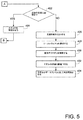
図4は図1に示す画像生成システム100の処理を例示するプロセスフローチャートを示す。ブロック402で走査対象オブジェクトを特定する。ブロック404でオブジェクトに隣接する第1の位置にスキャナ104の位置決めを行う。ブロック406で、ポイントスキャナ114とカラースキャナ116とが同期作動して、オブジェクトを走査する。ポイントスキャナ114により出力される幾何学的な点データと、カラースキャナ116により出力される色点データとは、ブロック408で画像データとして収集され、記憶される。
FIG. 4 is a process flowchart illustrating the processing of the
ブロック410で、衛星による測位システム120によって測定が行われ、スキャナ104の地理上の位置が記録される。ブロック412で、勾配方向センサ122による測定が行われ、スキャナ104のピッチ、ロールおよび向きが記録される。ブロック414で位置情報が記憶される。ブロック416で、オブジェクトの走査済み表面を表わす3次元電子画像であるポイントクラウドが走査から展開される。ブロック418で、幾何学的な点データが色点データと関連づけられて、3次元電子画像の色づけが行われる。ブロック420でポイントクラウドは位置決め情報と関連づけられる。
At
ブロック422で、追加走査を行うべきかどうかが判定される。追加走査を行うべきである場合、ブロック424で別の地理上の位置へスキャナを移動させることができ、処理はブロック406へ戻って、データをキャプチャし、別の3次元電子画像が展開される。追加走査が必要でない場合、上記位置情報を用いて各々の3次元電子画像から得られる画像データが組み合わされ、ブロック426でオブジェクトの3次元電子モデルが開発される。ブロック428で、オブジェクト上に存在する実際のテクスチャに基づいて、1または2以上のソーステクスチャが選択される。ソーステクスチャを用いて、複合テクスチャと、対応する変換処理手順とがブロック430で展開される。ブロック432で、ソーステクスチャと変換処理手順(複合テクスチャなど)とは3次元電子モデルの1または2以上の表面と関連づけられる。この3次元電子モデルは、ブロック434でデータファイルとして利用可能である。
At
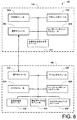
図6は、サイト計算システム106と実験室計算システム108とを備えた計算システム102の一例を示すさらに詳細なブロック図である。サイト計算システム106の例には、通信モジュール602、メモリモジュール604、プロセッサモジュール606およびユーザーインタフェースモジュール608が含まれる。さらに、サイト計算システム106は予備の位置合わせモジュール610を備えるものであってもよい。別の例では、大小様々な数のモジュールを用いてサイト計算システム106の機能を例示することができる。
FIG. 6 is a more detailed block diagram illustrating an example of a
通信モジュール602は、スキャナ104(図1)との通信および実験室計算システム108との通信を行うことが可能な装置であってもよい。さらに、通信モジュール602は、スキャナ104(図1)と関連する入出力(I/O)機能を提供するデータ収集機能を備えたものであってもよい。このI/O機能は、入出力チャネル、通信ポート、信号変換、フィルタリング、バッファリング、通信、光通信および/または他の任意のI/O関連機能を備えることができる。信号入出力の例には、アナログ信号、デジタル信号、並びに、RS422、TCP/IP、ブルートゥース、802.11、SMS、独自プロトコル、およびその他の任意の通信プロトコルなどの通信プロトコルが含まれる。
The
メモリモジュール604は、データを記憶し、検索することができるメモリデバイスあるいは媒体であってもよい。例えば、メモリモジュール604は、フラッシュメモリ、ランダムアクセスメモリ(RAMおよび/またはハードドライブ、光ディスクなどのような磁気メモリなどの電子メモリを備えるものであってもよい。メモリモジュール604に記憶され、メモリモジュール604からアクセスされたデータは走査画像および他のスキャナ関連データを含むようにしてもよい。さらに、画像生成システム100(図1)の範囲内のモジュールの機能および処理と関連するコンピュータコード/ソフトウェアなどの処理命令は記憶とアクセスとを行うことができる。したがって、メモリモジュール604に記憶された命令とデータとは、サイト計算システム106内の別のモジュールの機能上および処理上の協働作業を行うことができる。単一のモジュールとして示されてはいるが、メモリモジュール604はマルチメモリモジュールを備えたものであってもよい。これらのマルチメモリモジュールは画像生成システム100の別のモジュールをサポートすることも可能である。
The
プロセッサ606は、通信モジュール602、メモリモジュール604、ユーザーインタフェースモジュール608および予備の位置合わせモジュール610とインタフェースすることが可能な任意の制御ユニットまたはコンピュータベースの装置であってもよい。通信モジュール602とのインタフェースを行うステップは、入力信号および/またはデータを受け取り、送出信号および/またはデータの生成を目的とするステップを含むようにしてもよい。メモリモジュール604とのインタフェースを行うステップは、メモリモジュール604に記憶された命令を実行して、画像生成システム100(図1)の処理と関連して、メモリモジュール604の範囲内で、データを生成し、記憶し、操作しおよび/または抽出するステップを含むようにしてもよい。プロセッサ606は、サイト計算システム106の処理を調整し、通信モジュール602、メモリモジュール604、ユーザーインタフェースモジュール608および予備の位置合わせモジュール610の間でデータの交換を行うものであってもよい。
The
ユーザーインタフェースモジュール608は、機能サポート用ボタン、表示画面、タッチスクリーン、インジケータ、トランスデューサおよび/または画像生成システム100(図1)にユーザ用インタフェースを提供する任意のメカニズムを備えることも可能である。さらに、ユーザーインタフェースモジュール608は、3次元電子画像の目に見える描画、幾何学的な点、色点、3次元電子モデル、位置情報、および、画像生成システムが収集した他の任意のデータを提供することができる。ユーザーインタフェースモジュール608の処理は、プロセッサ606による実行命令と、ユーザから得た入力とに基づくようにしてもよい。
The
予備の位置合わせモジュール610は、ユーザーインタフェースモジュール608を用いて協働処理を行って、プロセッサ606が実行する命令に基づいて走査を表示し、走査処理を行ってもよい。走査処理の実行は、異なる走査の各々と関連づけられた3次元電子画像の移動と回転とをユーザが手動で行うステップを含むようにしてもよい。ポイントクラウドの移動と回転とを行って、ポイントクラウドを一体としてフィットさせ、3次元電子画像から得られる予備用3次元電子モデルの形成してもよい。
The
個々の走査処理を結合して、3次元電子モデルを形成するプロセスは“位置合わせ”と呼ばれる。この場合、位置合わせはオンサイトで手動で行ってもよく、したがって、“予備の位置合わせ”または“一時的位置合わせ”と呼ばれる場合もある。ユーザによる走査処理の操作が、オブジェクトの走査を行うサイトで行われるため、ユーザは、異なる3次元電子画像を合成する際、視覚によって予備用3次元電子モデルを実際のオブジェクトと比較することができる。 The process of combining the individual scanning processes to form a three-dimensional electronic model is called “alignment”. In this case, the alignment may be performed manually on-site and is therefore sometimes referred to as “preliminary alignment” or “temporary alignment”. Since the scanning operation by the user is performed at the site where the object is scanned, the user can visually compare the preliminary three-dimensional electronic model with the actual object when synthesizing different three-dimensional electronic images. .
さらに、予備の位置合わせモジュール610は走査の自動化操作を行って予備の3次元電子モデルを形成することができる。自動化操作は、ポイントクラウドと、走査の各々から得られる位置情報とを利用して、予備用3次元電子モデルの形成を図るステップを含むようにしてもよい。自動化操作に続いて、前述したように、ユーザは種々のポイントクラウドをさらに手動で操作することも可能である。操作が終了したとき、実験室計算システム108へ予備用3次元電子モデルを提供することができる。
Further, the
上記とは別に、操作を行わずに実験室計算システム108に対して走査を行ってもよい。サイト計算システム106に関する走査処理操作を行わない場合、予備の位置合わせモジュール610を省いてもよい。それに応じて、収集されたままの走査画像を送信したり、或いは、さらなる処理を行うために実験室計算システム108へ上記走査結果を出力したりすることも可能である。
Separately from the above, the
図6に示す実験室計算システム108の例は、通信モジュール622、メモリモジュール624、プロセッサモジュール626およびユーザーインタフェースモジュール628を備えるものである。さらに、実験室計算システム108は、走査合成用モジュール630と、幾何学モデル化モジュール632と、テクスチャライジングモジュール634とを備えるものであってもよい。別の例では、大小様々な数のモジュールを用いて実験室計算システム108の機能を例示することができる。
The example of the
通信モジュール622、メモリモジュール624、プロセッサモジュール626およびユーザーインタフェースモジュール628は、サイト計算システム106に含まれる前述した通信モジュール602、メモリモジュール604、プロセッサモジュール606およびユーザーインタフェースモジュール608と類似したものであってもよい。プロセッサモジュール626は、メモリモジュール624を備える別のモジュールに記憶された命令を実行することにより、実験室計算システム108の処理全体を制御することも可能である。さらに、プロセッサモジュール626は、通信モジュール622、メモリモジュール624、ユーザーインタフェースモジュール628、走査合成用モジュール630、幾何学モデルモジュール632とテクスチャライジングモジュール634の協働処理を可能にするものであってもよい。
The
実験室計算システム108は“正確な位置合わせ”と呼ばれる位置合わせプロセスを行うことも可能である。個々の3次元電子画像のポイントクラウド内の幾何学的な点が走査合成用モジュール630により結合されるとき、正確な位置合わせが行われる。さらに、結合済みポイントクラウドを一体として正確にフィットさせて、幾何学モデルモジュール632を用いて最終3次元電子モデルを形成することができる。
The
予備の位置合わせが行われたとき、実験室計算システム108によって3つの技法のうちのいずれかを用いて、正確な位置合わせを実施することができる。第1の技法では、個々の電子3次元画像を表す個々のポイントクラウドを合成して、個々のポイントクラウドのすべての画像データを含むモデルポイントクラウドを形成することができる。ポイントクラウドと位置合わせを行う操作は、異なる走査の範囲内の一致する幾何学的な点を特定するステップを含むようにしてもよい。種々のポイントクラウドが位置合わせされ、合成されて、モデルポイントクラウドが形成されるとすぐに、モデルポイントクラウドの範囲内の表面を決定することが可能となる。
When preliminary alignment is performed, accurate alignment can be performed by the
プロセッサ626により実行される命令は、モデルポイントクラウドの範囲内の幾何学的な点を結合して、表面を表わすことができる。走査合成用モジュール630によって幾何学的な点から表面を決定してもよい。表面の決定は、ポイントクラウドの範囲内の囲繞する幾何学的な点と関連して幾何学的な点を分析するステップを含むようにしてもよい。
The instructions executed by
少なくとも2つの幾何学的な点を含む表面をまず特定することができる。この特定された表面と別の幾何学的な点との間の所定の距離を用いて、この幾何学的な点が特定された表面の一部であるかどうかを判定することができる。例えば、表面と幾何学的な点との間で法線ベクトルを特定してもよい。幾何学的な点が、5センチメートルなど所定の距離の範囲内にあれば、表面と再計算された表面とに幾何学的な点を割り当てることができる。相互の所定の距離の範囲内の幾何学的な点のすべては、表面の一部として含まれるものと考えてもよい。幾何学的な点がマルチ表面の所定の距離の範囲内にあれば、この幾何学的な点はオブジェクトのコーナーまたはエッジであってもよく、したがって、マルチ表面の各々にこの幾何学的な点を割り当ててもよい。モデルポイントクラウドの範囲内に表面が決定されるとすぐに、結合済みポイントクラウドを一体として正確にフィットさせて、幾何学モデルのモジュール632を用いて最終3次元電子モデルを形成することができる。さらに、テクスチャを表面と関連づけることができる。
A surface containing at least two geometric points can first be identified. A predetermined distance between the identified surface and another geometric point can be used to determine whether the geometric point is part of the identified surface. For example, a normal vector may be specified between the surface and the geometric point. If the geometric point is within a predetermined distance, such as 5 centimeters, it can be assigned to the surface and the recalculated surface. All geometric points within a predetermined distance from each other may be considered to be included as part of the surface. If the geometric point is within a predetermined distance of the multi-surface, this geometric point may be a corner or an edge of the object, and thus this geometric point on each of the multi-surfaces. May be assigned. As soon as the surface is determined within the model point cloud, the combined point cloud can be accurately fitted together to form the final 3D electronic model using the
第2の技法では、表面は個々のポイントクラウドの形で個々に決定される。前述したように、ポイントクラウドの形の幾何学的な点に基づいて、表面を決定してもよい。表面が特定されるとすぐに、この表面とテクスチャとを関連づけることができる。次いで、ポイントクラウドの合成が可能となる。この技法でのポイントクラウドの合成は、個々のポイントクラウド内の個々の幾何学的な点の代わりに、表面および/またはテクスチャに基づくようにしてもよい。ポイントクラウドが合成されるすぐに、結合済みポイントクラウドを一体として正確にフィットさせて、幾何学モデルモジュール632を用いて最終3次元電子モデルを形成することができる。
In the second technique, the surface is determined individually in the form of individual point clouds. As described above, the surface may be determined based on geometric points in the form of a point cloud. As soon as a surface is identified, it can be associated with a texture. The point cloud can then be synthesized. The synthesis of point clouds with this technique may be based on surfaces and / or textures instead of individual geometric points within individual point clouds. As soon as the point clouds are synthesized, the combined point clouds can be accurately fitted together to form the final 3D electronic model using the
第3の技法では、表面は、個々のポイントクラウドの中で幾何学的な点から個々に決定される。表面が決定されるとすぐに、個々の表面のアウトラインが決定される。個々の表面のアウトラインは、3次元電子画像の各々を描くフレームワークを形成する。次いで、個々の走査のフレームワークを合成して、フレームワークモデルを形成するようにしてもよい。フレームワークの合成は、種々のポイントクラウドからの表面のアウトラインのアラインメントに基づくようにしてもよい。ポイントクラウドが結合されるとすぐに、結合済みポイントクラウドを一体として正確にフィットさせて、幾何学モデルモジュール632を用いて最終3次元電子モデルを形成することができる。さらに、テクスチャを表面と関連づけることができる。
In the third technique, the surface is determined individually from geometric points in individual point clouds. As soon as the surface is determined, the outline of the individual surface is determined. The individual surface outlines form a framework for drawing each of the three-dimensional electronic images. The individual scan frameworks may then be combined to form a framework model. The composition of the framework may be based on the alignment of surface outlines from various point clouds. As soon as the point clouds are combined, the combined point clouds can be accurately fitted together to form a final three-dimensional electronic model using the
予備の位置合わせが行われていないとき、正確な位置合わせは、個々のポイントクラウド内の色点と幾何学的な点とを結合して、ラインを形成するステップを含むようにしてもよい。走査合成用モジュール630内の命令によって色点と幾何学的な点とを結合することができる。幾何学的な点と色点とを用いて表された3次元電子画像から、1または2以上のラインを用いて表された同じ3次元電子画像へのポイントクラウドの変換を行うことができる。このようにして、選択された数の幾何学的な点が単一の1本のラインに変換される。
When preliminary alignment is not performed, accurate alignment may include the step of combining color points and geometric points in individual point clouds to form lines. Color points and geometric points can be combined by instructions in the
ラインの各々は、アウトラインデータで表されるラインであってもよい。アウトラインデータによって、データ操作機能において著しく大きな効率を得ることが可能となる。というのは、単一ラインによって、ポイントクラウド内の比較的多数の幾何学的な点と色点とを置き換えることが可能となるからである。例えば、ポイントクラウドが、ビルであるオブジェクトを表わす場合、走査合成用モジュール630は、3次元電子画像からビルの断面のラインを生成する命令を実行することができる。したがって、個々の走査用としてアウトラインデータファイルを生成することができる。
Each of the lines may be a line represented by outline data. Outline data can provide significantly greater efficiency in data manipulation functions. This is because a single line can replace a relatively large number of geometric and color points in the point cloud. For example, if the point cloud represents an object that is a building, the
図7は、家屋であるオブジェクトの走査から展開された3次元電子画像702の一例である。アウトラインデータファイルを生成するために、走査のポイントクラウドから展開された3次元電子画像702はサブイメージ704に分割することができる。例えば、3次元電子画像702は、個々に1メートル厚のサブイメージ704に分割することができる。
FIG. 7 is an example of a three-dimensional
サブイメージ704への分割には、ポイントクラウドをセグメントに“スライスする”ステップが含まれる。これらの“スライス”は垂直方向のもの、水平方向のもの、傾斜したものなどであってもよい。サブイメージ704の各々の範囲内で、単一の1本のラインであるライン706を展開することができる。ライン706は、サブイメージ(ポイントクラウドのセグメントなど)を表す。図7の例では、ライン706の第1の部分708はこの家屋の第1の壁を形成するポイントクラウドの部分を表わすことができる。ライン706の第2の部分710は屋根の第1の片側部分を表わすことができる。さらに、ビルなどのオブジェクトを水平方向に仕切って、部分的フロア平面712であるサブイメージに変えることができる。同様に、部分的フロア平面712は1つのラインに展開することも可能である。サブイメージの形成が可能なアプリケーションの一例として、サイラ・テクノロジ社(カリフォルニア州サンラモン)から入手可能なサイクルワンソフトウェアがある。
Dividing into
ラインにより表される個々のサブイメージをアウトラインデータファイルに記憶し、幾何学モデルモジュール632(図6)へこのサブイメージを入力してもよい。例えば、アウトラインデータファイルの各々は、dxfや.dwgファイルであってもよい。個々のサブイメージを描くポイントクラウドの個々の部分の複雑さとサイズとがラインにまで縮小しているため、3次元電子画像に関連する必要なデータ記憶容量と、データ転送容量と、処理パワーとの減少が可能となる。さらに、各々の走査からのラインの操作によって3次元電子モデルの形成が単純化される。 Individual sub-images represented by lines may be stored in an outline data file and input to the geometric model module 632 (FIG. 6). For example, each of the outline data files includes dxf,. It may be a dwg file. Because the complexity and size of the individual parts of the point cloud that draw the individual sub-images are reduced to lines, the required data storage capacity, data transfer capacity and processing power associated with 3D electronic images Reduction is possible. In addition, the manipulation of lines from each scan simplifies the formation of a three-dimensional electronic model.
図6の幾何学モデルモジュール632は、3次元電子画像の正確な合成により、走査の正確な位置合わせを終了させ、3次元電子モデルの開発命令を含むようにしてもよい。さらに、幾何学モデルモジュール632は、幾何学的関連データを走査データに追加して、3次元電子モデルの開発を行うことも可能である。幾何学モデルモジュール632の一例には、Graphisoft(登録商標)US社(マサチューセッツ州、ニュートン)から入手可能なArchiCAD(登録商標)ソフトウェアが含まれる。
The
個々の3次元電子画像内の走査合成用モジュール630により特定される表面は、幾何学モデルモジュール632により組み立てられて、3次元電子モデルに変えられたものであってもよい。上記とは別に、3次元電子画像の各々が、ラインの形の幾何学的サブイメージにまで縮小されたものである場合、幾何学モデル化用モジュール632によりこれらのラインを同様に組み立てて、3次元電子モデルの形成を図ることも可能である。サイト計算システム106から予備用3次元電子モデルを入力する場合、幾何学モデルモジュール632を用いて正確な位置合わせ中に3次元電子画像をさらに操作して、最終3次元電子モデルの形成を図ることができる。幾何学モデルモジュール632により行われる正確な位置合わせの部分は、種々のポイントクラウドのさらに詳細な処理を行って、種々の3次元電子画像を一括してさらに精密にフィットさせて、幾何学画像に変換するステップを含むようにしてもよい。
The surface specified by the
さらに精密に3次元電子画像を一体としてフィットさせる詳細な処理を行って、3次元電子モデルを形成するステップは、自動化により行ってもよいし、手動により行ってもよいし、あるいは手動と自動との何らかの組み合わせにより行ってもよい。この詳細な処理中の3次元電子画像の操作と合成は、3次元電子画像の位置および/または回転を変更して、3次元電子画像を一体として正確にフィットさせるようにする命令を含むようにしてもよい。測位システム112により決定された位置情報に基づいて相互に関連して3次元電子画像の操作を行ってもよい。3次元電子画像がラインに分割された場合、幾何学モデルモジュール632を用いてサブイメージを表すラインを合成して、操作することも可能である。
The step of forming a three-dimensional electronic model by performing detailed processing for fitting a three-dimensional electronic image as a single unit more precisely may be performed automatically, manually, or manually and automatically. You may carry out by some combination of. This detailed processing and synthesis of the three-dimensional electronic image may include instructions for changing the position and / or rotation of the three-dimensional electronic image to accurately fit the three-dimensional electronic image together. Good. Based on the position information determined by the positioning system 112, the three-dimensional electronic image may be manipulated in relation to each other. When a three-dimensional electronic image is divided into lines, the
3次元電子画像の操作と合成は、一体に近接している第1の3次元電子画像のポイントクラウドの範囲内の幾何学的な点(表面を形成する点など)を特定し、第1の3次元電子画像内の幾何学的な点と、第2の3次元電子画像内の幾何学的な点との間の距離を測定するステップを含むようにしてもよい。ガウスベースの計算法などの反復処理を用いて、第2の3次元電子画像内の幾何学的な点と類似している第1の3次元電子画像内の幾何学的な点を特定することができる。 The manipulation and synthesis of the three-dimensional electronic image specifies a geometric point (such as a point forming a surface) within the point cloud range of the first three-dimensional electronic image that is close together, Measuring the distance between a geometric point in the three-dimensional electronic image and a geometric point in the second three-dimensional electronic image may be included. Identifying a geometric point in the first three-dimensional electronic image that is similar to the geometric point in the second three-dimensional electronic image using an iterative process such as a Gauss-based calculation method Can do.
異なる3次元電子画像内の同様の幾何学的な点の間での誤差に基づいて、誤差が最少化されるまで操作と再計算の反復を行うことができる。この誤差は、異なる3次元電子画像の隣接する幾何学的な点間のすべての2乗距離の加重を含む2乗誤差最小化法に基づいて決定してもよい。ポイントクラウドがサブイメージに分割された場合、ライン間の距離を用いてラインの操作と合成とを同様に行うことができる。 Based on the error between similar geometric points in different three-dimensional electronic images, iterative manipulation and recalculation can be performed until the error is minimized. This error may be determined based on a square error minimization method that includes a weight of all the square distances between adjacent geometric points of different 3D electronic images. When the point cloud is divided into sub-images, line manipulation and composition can be performed in the same manner using the distance between lines.
また、幾何学モデルモジュール632によって正確な位置合わせ中にカラーを操作して、3次元電子モデルを生成することも可能である。色点は幾何学的な点と同期して収集してもよい。したがって、3次元電子画像内の幾何学的な点と色点とを関連づけることが可能となる。例えば、1つの色点は9個の幾何学的な点と関連づけることが可能であり、したがって、幾何学的な点の間で色点の補間が可能となる。
The
上記とは別に、カラーが幾何学的な点と同期して収集されない場合、ストレッチングとスキューイングとを利用して、幾何学的な点と関連づけることができる。例えば、電子的に表されたオブジェクトのカラー用として写真を用いる場合、写真のカラーのストレッチングとスキューイングとを行って、幾何学的表面を幾何学的な点またはラインとフィットさせることができる。 Alternatively, if the color is not collected synchronously with the geometric point, stretching and skewing can be used to associate it with the geometric point. For example, if a photograph is used for the color of an electronically represented object, the color of the photograph can be stretched and skewed to fit the geometric surface with geometric points or lines. .
動作中、個々の3次元電子画像を合成した方法についての変換および回転情報を利用して、幾何学的な点に対してカラー・ピクセルを対応づけることができる。異なる走査時の同じ領域から得られるカラーの違いは。対応画像の画像比較、対応ピクセルのピクセル比較、あるいは、異なる走査間でのこのような違いを分析するその他の任意の画像処理技術などの画像処理技術を利用する幾何学モデルモジュール632により分析される。さらに、ナビゲーション座標を利用して、異なる個々の走査処理中の太陽光線の角度(例えば陰影など)の差を決定することも可能である。さらに、色点間の表面色の空隙を塗りつぶすことができる。この空隙の塗りつぶしは例えば、ラスタ化処理によって、囲繞する色を補間することにより完成することができる。
In operation, color pixels can be associated with geometric points using transformation and rotation information for the method of combining individual 3D electronic images. What is the difference in color from the same area during different scans? Analyzed by the
3次元電子画像の表面を分画して複数の三角形に変えることにより、幾何学モデルモジュール632によってラスタ化処理を行うことができる。表面の範囲内の幾何学的な点を選択的に接続することにより、これらの三角形をオーバーラップしないようにし、上記三角形を形成して、点三角形の形成を図るようにしてもよい。幾何学的な点間のラインは個々の点三角形の3辺を描くことができる。さらに、境界三角形を形成することができる。
Rasterization processing can be performed by the
表面の周縁の周りにある幾何学的な点と境界との間でこれらの境界三角形を形成することができる。この境界を形成して、表面の外縁部の周りの表面を囲繞することができる。幾何学的な点を用いて上記境界三角形を形成して、個々の境界三角形の3辺のうちの2辺が、幾何学的な点から境界へ延伸するように図ることができる。境界三角形の各々の第3の辺は境界により形成することができる。 These boundary triangles can be formed between geometric points around the perimeter of the surface and the boundary. This boundary can be formed to surround the surface around the outer edge of the surface. Geometric points can be used to form the boundary triangle so that two of the three sides of each boundary triangle extend from the geometric point to the boundary. The third side of each boundary triangle can be formed by a boundary.
表面と関連づけられる色点を用いて、各々の三角形の範囲内の既存の色点のシェーディングを形成することができる。これらの既存の色点間の各々の三角形内に新たな色点を追加することによりシェーディングを形成することができる。追加される新たな色点の数は、表面に所望する詳細情報(分解能)の量に基づくようにしてもよい。 The color points associated with the surface can be used to form a shading of existing color points within each triangle. Shading can be formed by adding a new color point within each triangle between these existing color points. The number of new color points added may be based on the amount of detailed information (resolution) desired on the surface.
新たな色点の決定は、既存の色点間のカラー・スペクトルの範囲内で移動することによりカラー・ブレンディングに基づくようにしてもよい。カラー・ブレンディングは、既存の色点間の補間と、種々の既存の色点からの新たな色点の距離の差および/または既存の色点間のカラー・スペクトルの範囲内で移動する他の任意のカラー進化技術により実行することができる。ラスタ化の結果、各々の三角形により画定される表面領域のシェーディングは同じ状態のままにすることが可能であり、カラーに対してわずかな調整を行うことが可能であり、および/または、著しく異なるカラーを施すようにすることが可能である。個々の三角形は、任意の数のカラーまたは個々の三角形内の既存の色点および/または近接する三角形内の既存の色点に相応するカラー変動を含むようにしてもよい。 The determination of a new color point may be based on color blending by moving within the color spectrum between existing color points. Color blending is the interpolation between existing color points and the difference in distance of new color points from various existing color points and / or other moving within the color spectrum between existing color points. It can be implemented by any color evolution technique. As a result of rasterization, the shading of the surface area defined by each triangle can remain the same, minor adjustments can be made to the color, and / or significantly different It is possible to apply color. Individual triangles may include any number of colors or color variations corresponding to existing color points within individual triangles and / or existing color points within adjacent triangles.
幾何学モデルモジュール632は3次元電子モデルを編成して、所定の構造に変えることも可能である。幾何学モデルモジュール632を用いてモデル化したオブジェクトの電子表示物の構造を層に分画することができる。3次元電子モデルからなるこれらの層は、単純な層である第1の層、構造層である第2の層、位置層である第3の層、ライブラリ層である第4の層、および、画像層である第5の層を含むことができる。上記単純な層は、走査済みのオブジェクトを表す3次元の幾何学的構造を含むようにしてもよい。この構造層は、直線、曲線、スプライン、点、テキスト情報、コメントおよび3次元電子モデルの構成プロセス中に利用したその他の任意の作成関連情報などのコンポーネントを含むようにしてもよい。
The
位置層には、走査データが収集されたときのスキャナ104の位置に関連する情報が含まれる。位置層情報はサイトの平面スケッチとマークした位置とを含むようにしてもよい。このマーク位置は、地理上の座標、並びに、走査中に位置システム112(図1)により得られる勾配と高度とを提供することができる。情報はサイトの平面スケッチの範囲内に表示することができる。
The position layer includes information related to the position of the
サイトの平面スケッチは、3次元電子モデルと同じ縮尺、位置および向きに合わせた表示可能な実例であってもよい。北のような所定の方向からの分散はサイトの平面スケッチで特定することができる。このサイトの平面スケッチは3次元電子モデルの表示を行うことも可能である。サイトの平面スケッチ内の3次元の電子モデルの向きは、オブジェクトの北方向がディスプレイの上縁部に隣接するようにすることができる。 The planar sketch of the site may be an example that can be displayed in the same scale, position, and orientation as the three-dimensional electronic model. The variance from a given direction, such as north, can be identified with a planar sketch of the site. The plane sketch of this site can also display a 3D electronic model. The orientation of the three-dimensional electronic model in the planar sketch of the site can be such that the north direction of the object is adjacent to the top edge of the display.
ライブラリ層は命令とデータの形でライブラリ要素を含むようにしてもよい。ライブラリ要素を構成して、モデル化処理で利用し、モデル化されたオブジェクトの種々の態様を表わすようにすることができる。ライブラリ層は、ソーステクスチャを変換して複合テクスチャを形成する変換処理手順を含むことも可能である。画像層はオプションの層であってもよい。オブジェクトの写真を撮影した場合、画像層は、写真撮影時の撮影者の地理上の位置、並びに、撮影者の氏名などの一意の識別子のスケッチを含むようにしてもよい。 The library layer may include library elements in the form of instructions and data. Library elements can be configured and utilized in the modeling process to represent various aspects of the modeled object. The library layer can also include a conversion procedure that converts the source texture to form a composite texture. The image layer may be an optional layer. When a picture of an object is taken, the image layer may include a sketch of a unique identifier such as the photographer's geographic location at the time of photography and the name of the photographer.
3次元電子モデルを用いてモデル化した個々のオブジェクトの幾何学的構造のモデルサイズは、均等なサイズに合わせて縮尺を行うことができる。オブジェクトは、複数のポリゴンを持つモデルによって所定の縮尺で幾何学的に表わすことができる。オブジェクトを表わす選択されたポリゴンの数は、所望の分解能、ハードウェア上の制限あるいはパフォーマンスや表示に影響を与えるその他の任意の考慮事項に基づいて選択することができる。例えば、10個の異なる電子モデルをディスプレイに1秒で描画することを望み、グラフィックプロセッサに1秒で10,000個のポリゴンを描画する制限がある場合、3次元電子モデルでは1000個のポリゴンまでオブジェクトの幾何学的形状を表わすことができる。ポリゴンの各々は、n個の頂点を含むものであってもよい(但しn>2)。 The model size of the geometric structure of each object modeled using the three-dimensional electronic model can be scaled to an equal size. An object can be represented geometrically at a predetermined scale by a model having a plurality of polygons. The number of selected polygons representing the object can be selected based on the desired resolution, hardware limitations, or any other consideration that affects performance or display. For example, if you want to draw 10 different electronic models on the display in 1 second, and the graphic processor has a limit of drawing 10,000 polygons in 1 second, the 3D electronic model has up to 1000 polygons. The geometric shape of the object can be represented. Each polygon may include n vertices (where n> 2).
3次元電子モデルの構造は専ら1または2以上の平面から構成することができる。壁、天井、屋根などのような各々の平面は、ゼロの深さ(厚さ)を持つものであってもよい。色点が幾何学的な点と同期してキャプチャされなかった場合、3次元電子モデル内の平面の特徴的表面は所定のカラーで示すことができる。このカラーは、一般に、レンガ=赤、草木=緑などのような表示されたマテリアルに似たカラーであってもよい。さらに、ドア、窓、色付けされた建物外面の模様などの種々の平面の表面上の特徴の視覚表示はモデル化されていない。オブジェクトの表面上の特徴の表示は3次元電子モデルにテクスチャを追加することにより実現することができる。 The structure of the three-dimensional electronic model can be composed exclusively of one or more planes. Each plane, such as a wall, ceiling, roof, etc., may have zero depth (thickness). If the color point is not captured synchronously with the geometric point, the planar characteristic surface in the three-dimensional electronic model can be shown in a predetermined color. This color may generally be a color similar to the displayed material, such as brick = red, vegetation = green, etc. Furthermore, visual representations of features on various planar surfaces such as doors, windows, and colored exterior building patterns are not modeled. Display of features on the surface of the object can be realized by adding a texture to the three-dimensional electronic model.
3次元電子モデルを形成する3次元電子画像はオーバーラップしたものとして視覚的に表されるべきではない。したがって、平面の辺並びにモデルの範囲内で互いに接触する外側の辺は閉じられることが望ましい。すなわち、3次元電子モデルの視覚的表示は、視覚的に感知される実際のオブジェクトの中に存在しない孔、斜線あるいはその他の割れ目をいずれも含まないようにすることが望ましい。さらに、3次元電子モデルのボリュームコンポーネントは閉じられる。例えば、オブジェクトがビルである場合、典型的3次元電子モデルの一階は閉じたアウトラインを持つようにすることも可能である。 The 3D electronic images that form the 3D electronic model should not be visually represented as overlapping. Therefore, it is desirable that the sides of the plane as well as the outer sides that contact each other within the model are closed. That is, it is desirable that the visual display of the three-dimensional electronic model does not include any holes, diagonal lines or other cracks that do not exist in the visually perceived actual object. Furthermore, the volume component of the 3D electronic model is closed. For example, if the object is a building, the first floor of a typical 3D electronic model can have a closed outline.
幾何学モデルモジュール632は高さ補正を含むようにしてもよい。3次元電子モデルの範囲内で高さ補正を適用して、傾斜と別の勾配とをシミュレートすることも可能である。ディスプレイ上のオブジェクトを表すグラフィック画像を平面上に投影してもよい。平面は地面、駐車場、通りなどのような残りの表面を表わすことも可能である。斜面を形成するために残りの表面が傾斜している場合、高さ補正を適用することも可能である。
The
図8は、丘陵の斜面などの斜面806上に配置されるオブジェクト804を表す3次元電子画像802の一例を示すものである。例示のオブジェクト804はビルである。走査対象のかなりの傾斜面上に位置するオブジェクトは、斜面を考慮にいれない3次元電子モデルを結果として生じる場合がある。すなわち、このオブジェクトは一部分が抜け落ちて表されているように見える場合がある。
FIG. 8 shows an example of a three-dimensional
幾何学モデルモジュール632は、表されたオブジェクト804の幾何学的形状の顕著な違いを伴うことなく、標高(elevation)を変化させることによりモデルの外側の辺を“均等化”しないようにすることができる。図示の例では、オブジェクト804のアウトラインには一階808が含まれる。一階808はアーキトレーブブロック810構造用の基礎部分を提供して、高度の変動を補正することができる。アーキトレーブブロック810は一階806から生成することも可能である。オブジェクト804をフィットさせるアーキトレーブブロック810の調整は調整点(Zmin)に基づくようにしてもよい。
The
図9は、3次元電子画像902の別の例を示す図である。3次元電子画像902にはストリート面904とブリッジ906の表示が含まれる。ストリート面904とブリッジ906との間の推移は、フローティングとして表わすことができる。“フローティング”という用語はストリート面904とブリッジ906との間の角関係を意味する。図示の例では、互いにフランク(flank)する角度は約6レベルまで異なるものであってもよい。
FIG. 9 is a diagram illustrating another example of the three-dimensional
図6に例示のテクスチャライジングモジュール634は、3次元電子モデルの1または2以上の表面を対象とする1または2以上のテクスチャの生成命令を含むテクスチャライジングシステムである。3次元電子画像の表面用または他の任意の形式のオブジェクトの電子表示物用のテクスチャライジングシステムを用いてテクスチャを生成することも可能である。したがって、テクスチャライジングシステムを用いて形成されるテクスチャは、3次元電子画像および/または前述したように生成されるモデルの表面の表示に限定されるものではない。さらに、テクスチャライジングシステムは画像生成システムの前述した例での処理に限定されるものではない。代わりに、テクスチャライジングシステムは、スタンドアロン型システムであってもよいし、あるいは、電子画像の出力が可能な任意のシステムと協働して処理を行うものであってもよい。
The
テクスチャライジングモジュール634は新たなテクスチャの生成命令を含むようにしてもよい。この新たなテクスチャは既存のテクスチャの変更および/または合成により生成することも可能である。テクスチャライジングモジュール634は、複数のユーザがアクセス可能なテクスチャ・ライブラリをサポートする命令を含むようにしてもよい。テクスチャ・ライブラリ内のテクスチャを用いて、ビルなどのオブジェクトの3次元電子モデルをテクスチャライズすることができる。
The
図示の例では、テクスチャモジュール634は、テクスチャ高速生成用画像生成システム100の当該部分であってもよい。このテクスチャモジュール634の機能として、既存のテクスチャ(ソーステクスチャ)に基づいて、新たなテクスチャや調整済みテクスチャ(複合テクスチャ)の生成が可能であるという点が挙げられる。例えば、ビルのユニークな部分をソーステクスチャとして含む写真や画像からとることも可能である。ソーステクスチャ、異なるソーステクスチャおよび/または1または2以上のソーステクスチャの変換によりビルの種々の部分のテクスチャを表して、複合テクスチャを形成することも可能である。
In the illustrated example, the
したがって、写真や画像からとられるおそらく数百の異なるテクスチャの生成が減ることにより、コンピュータメモリとテクスチャのキャプチャ時のおよび/または生成時のかなりの費用の発生を避けることが可能となる。これといった特徴のないおよび/または魅力のないものとなる可能性がある単純な汎用的テクスチャへ戻ることなくこの節減を実現することが可能となる。ソーステクスチャの合成のほとんど無限の可能性によって、過度のメモリを費やすことなく3次元電子モデルに適合される望ましい複合テクスチャの生成が可能となる。すなわち、複合テクスチャの画像の代わりに、複合テクスチャの生成処理手順を記憶することができる。上記とは別に、複合テクスチャ自体を記憶することができる。 Thus, by reducing the generation of perhaps hundreds of different textures taken from photographs and images, it is possible to avoid incurring significant costs when capturing and / or generating computer memory and textures. This saving can be achieved without reverting to a simple generic texture that may be uncharacteristic and / or unattractive. The almost limitless possibilities of source texture synthesis allow the generation of desirable composite textures that are adapted to the 3D electronic model without consuming excessive memory. That is, a composite texture generation processing procedure can be stored instead of the composite texture image. Apart from the above, the composite texture itself can be stored.
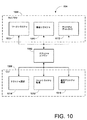
図10は、図6に例示のテクスチャライジングモジュール634の範囲内での命令を示すさらに詳細なブロック図の例である。テクスチャライジングモジュール634は、テクスチャエンジン1002、ライブラリコンポーネント1004およびグラフィックユーザインタフェース(GUI)コンポーネント1006を備える。別の例では、テクスチャライジングモジュール634の機能を表わすために大小様々な数のエンジンとコンポーネントを示すことができる。さらに、別の例では、テクスチャライジングモジュール634は、実験室計算システム108の外部で、および、実験室計算システム108から独立に動作することができる。
FIG. 10 is a more detailed block diagram example illustrating instructions within the
C++、ビジュアルベーシック、UNIX(登録商標)、Java(登録商標)、あるいは他の任意のソースコード言語でテクスチャライジングモジュール634内の命令を開発することも可能である。テクスチャライジングモジュール634の開発は、マイクロソフト(登録商標)社のビジュアルスタジオ、Borland社から出されているJビルダ、Borland社から出されているC++ビルダあるいは他の任意の開発用ツールを用いて行うことができる。別の例では、別の形式、フォーマットおよび/またはツールを用いてテクスチャライジングモジュール634内の命令を開発することができる。
It is also possible to develop instructions in the
テクスチャエンジン1002は、テクスチャライジングモジュール634の操作機能全体を出力する命令を備えることができる。さらに、テクスチャエンジン1002は、協働処理並びにライブラリコンポーネント1004とグラフィックユーザインタフェース・コンポーネント1006との制御を調整することも可能である。テクスチャエンジン1002によって、テクスチャライジングモジュール634は、ウィンドウズ(登録商標)9x、NT、2000およびXPのようなプラットフォームおよびネットワークアクセスの有無を問わずその他の任意のプラットフォームを処理することが可能となる。これに応じて、1つの例では、テクスチャライジングモジュール634のユーザインタフェースは、“ウィンドウズ(登録商標)様の”ルックアンドフィールを備えることができる。建築家、設計者などのようなユーザによる処理用としてテクスチャライジングモジュール634の設計を行うことが可能であり、したがって、ソフトウェア開発者の専門的知識を必要とせずに処理を行うことが可能となる。さらに、テクスチャライジングモジュール634は、訓練されていないユーザが誤って開始した有害なイベントから保護を行うセーフガード機能を装備することも可能である。
The
ライブラリコンポーネント1004はテクスチャ・ライブラリを表わし、テクスチャ・ライブラリ内のテクスチャライジングモジュール634の基本要素であるテクスチャを分類することができる。ライブラリコンポーネント1004の例はソーステクスチャカテゴリ1008と複合テクスチャカテゴリ1010とを備え、これら2つのカテゴリは分類できるテクスチャの種別を示すものである。別の例では、大小様々な数のカテゴリでテクスチャの種別を分類することができる。さらに、ライブラリコンポーネント1004はテクスチャディレクトリ1012を含むようにしてもよい。
本願明細書で使用されているように、“単数のテクスチャ”または“複数のテクスチャ”という用語は、オブジェクトの1または2以上の表面上で視覚的に感知される実際の色および/または特徴のリアルな表示を意味するものである。したがって、電子の形でオブジェクトの表面に貼り付けられる“テクスチャ”は、実際のオブジェクトを見ているとき、視覚的に感知されるオブジェクトの表面上の特徴をほとんど複製するものである。例えば、ビルの表面のテクスチャは、窓、彫刻、鋳物、手摺り、穴、積み煉瓦、こけら板、などを含むようにしてもよい。このテクスチャは、塗りたての表面、日陰の表面および/または陽の当たる表面を表わすものであってもよいし、同様に、反射光、表面上へ投影された光画像を表わすものであってもよい。このようにして、テクスチャを用いて、構造的特徴、芸術的特徴、照明およびオブジェクトの1または2以上の表面上に存在するその他の任意の視覚的特徴の複製あるいはほとんどの再現をあたかも実際のオブジェクトが観察されるかのように行うことができる。 As used herein, the term “single texture” or “plural textures” refers to actual colors and / or features that are visually perceived on one or more surfaces of an object. It means a realistic display. Thus, the “texture” that is affixed to the surface of an object in the form of an electron almost duplicates the features on the surface of the object that are visually perceived when looking at the actual object. For example, the texture of the building surface may include windows, sculptures, castings, handrails, holes, brickwork, shingles, and the like. This texture may represent a freshly painted surface, a shaded surface and / or a positive surface, as well as a reflected light, a light image projected onto the surface. . In this way, textures can be used to reproduce structural features, artistic features, lighting, and any other visual features present on one or more surfaces of the object, or to reproduce most of the actual object. Can be done as if observed.
ソーステクスチャカテゴリ1008には、少なくとも1つのソーステクスチャが含まれる。ソーステクスチャは、ソーステクスチャのカテゴリ1008に記憶することができる電子形式の画像である。画像は、ビットマップ、JPEG、TIF、DWGのような画像ファイルの形であってもよいし、あるいは、人、オブジェクト、あるいは他の任意の視覚的に感知される主題の光学的描写を示すその他の任意の電子形式であってもよい。画像の電子形式の範囲内に存在するピクセルは、画像のテクスチャを表わす赤、緑、青および透明なものであってもよい。例えば、ソーステクスチャは、デジタルカメラで撮影したデジタル写真から作成したものであってもよい。ソーステクスチャの1例として、ビルの建物外面のビットマップ画像がある。
The
複合テクスチャカテゴリ1010には複合テクスチャが含まれる。複合テクスチャは1または2以上のソーステクスチャから構成される。これらの複合テクスチャは、複合テクスチャカテゴリ1010の範囲内で変換処理手順を用いて表される。これらの変換処理手順は複合テクスチャカテゴリ1010に記憶することも可能である。変換処理手順は操作命令および/または合成命令を出力し、これらの命令は、ソーステクスチャカテゴリ1008内の1または2以上のソーステクスチャに適用されて、1または2以上の複合テクスチャを形成する。したがって、これらの複合テクスチャには、複合テクスチャを構成する元となるソーステクスチャの参照符号が含まれる。
The
変換処理手順に基づく1または2以上のソーステクスチャの変換は、1または2以上のソーステクスチャに対して行われる1または2以上の画像処理を含むようにしてもよい。これらの画像処理は、例えば、クリッピング、色付け、回転、鏡映、反復、縮尺、位置決め、ソート、および/または1または2以上のソーステクスチャの他の任意のグラフ関連操作を含むようにしてもよい。 The conversion of one or more source textures based on the conversion processing procedure may include one or more image processes performed on one or more source textures. These image processing may include, for example, clipping, coloring, rotation, mirroring, repetition, scaling, positioning, sorting, and / or any other graph related operation of one or more source textures.
図11は、ソーステクスチャ1102を用いて複合テクスチャ1100を構成する例示の変換処理手順の範囲内での個々の画像処理の結果を示す図である。ソーステクスチャ1102は、ブロック1104で変換処理手順によって特定される。ブロック1106で変換処理手順によってクリッピングが適用される。というのは、ソーステクスチャ1102の一部分のみを必要とするからである。ブロック1108で、1または2以上のカラーでソーステクスチャを多重層化することにより、変換処理手順による色付けが施される。ブロック1110で変換処理手順によってソーステクスチャ1102は回転される。図示の例では、ソーステクスチャ1102はほとんど90度のステップで回転され、その結果回転されたソーステクスチャ1102と新たな外接矩形との間の空間は透明な色で塗りつぶされる。別の例では、回転ステップは上記回転ステップよりも大きくてもよいし、小さくてもよい。
FIG. 11 is a diagram showing the results of individual image processing within the range of an exemplary conversion processing procedure that configures the composite texture 1100 using the
ブロック1112で、ソーステクスチャ1102はX軸とY軸上で鏡映される。ソーステクスチャ1102は、ブロック1114でX軸線とY軸線とに沿って複数回反復される。これらの反復されたソーステクスチャ1102は切れ目なく連続したものであってもよい。上記とは別に、反復された各ソーステクスチャ1102の間で透明な色で塗りつぶされる空隙を画定することができる。ブロック1116で、反復されるソーステクスチャ1102の縮尺がX軸とY軸に沿って行われる。フィルタリングなしでこの縮尺を行うことができる。上記とは別に、双一次フィルタリングあるいは他の任意の縮尺やフィルタリング技術を用いて縮尺を行ってもよい。
At
変換済みソーステクスチャ1102はアラインメントとソーティングとにより位置決めされ、ブロック1118で複合テクスチャ1100の少なくとも一部を形成することができる。これに応じて、マルチ変換済みソーステクスチャ1102の位置合わせを行って、複合テクスチャ1100を作成することができる。マルチ変換済みソーステクスチャ1102は、互いに切れ目のない連続したアラインメントを行うことができる。上記とは別に、2または3以上の変換済みソーステクスチャ1102のアラインメントを行ってオーバーラップさせることができる。オーバーラップするソーステクスチャ1102が存在する場合、変換処理手順の一部としてオーバーラップの順序を指定することができる。このオーバーラップの順序によって、複合テクスチャ1100を形成するために変換済みソーステクスチャ1102が置かれている特別の順序が提供される。
The transformed
複合テクスチャ1100は、最初、黒で塗りつぶすことができ、および/または、完全に透明なテクスチャにすることができる。所定の論理式に従って複合テクスチャ1100の範囲内でソーステクスチャ1102の変換と位置決めとを行うことができる。例えば、ソーステクスチャ1102の変換用論理式は以下のようなものとすることができる:R0=R0*(1−A1)+R1*A1 G0=G0*(1−A1)+G1*A1 式 I B0=B0*(1−A1)+B1*A1 A0=A0*(1−A1)+A1
但し、R0、G0、B0、A0は、複合テクスチャ1100の色(R=赤、G=緑、B=青)および透明度(A)であり、R1、G1、B1、A1はソーステクスチャ1102の色と透明度である。本例では、ソーステクスチャ1102の色と透明度は約0.0〜1.0の範囲内にある。
The composite texture 1100 can initially be filled with black and / or can be a completely transparent texture. The
However, R0, G0, B0, A0 are the colors (R = red, G = green, B = blue) and transparency (A) of the composite texture 1100, and R1, G1, B1, A1 are the colors of the
図10で、テクスチャディレクトリ1012はテクスチャライジングモジュール634用のツリー構造を与えることができる。テクスチャディレクトリ1012のツリー構造は識別子を分類することができる。テクスチャライジングモジュール634の範囲内のディレクトリは、テクスチャディレクトリ1012の範囲内の一意のディレクトリ識別子を用いて呼び出すことができる。一意のディレクトリ識別子は特定のディレクトリに対応する一意の数字および/または文字の組み合わせとすることができる。さらに、各々のディレクトリの範囲内で、少なくとも1つのソーステクスチャ用としておよび/または少なくとも1つの複合テクスチャ用として一意のテクスチャ識別子を指定することができる。一意のテクスチャ識別子は、テクスチャを一意に特定する数字および/または文字の任意の組み合わせとすることができる。ディレクトリを作成するとき、ソーステクスチャを記憶するとき、あるいは、変換処理手順を用いて複合テクスチャを形成するとき、一意のディレクトリ識別子とテクスチャ識別子とを割り当てることも可能である。
In FIG. 10,
図12はテクスチャディレクトリ1012の一例である。例示のテクスチャディレクトリ1012には、少なくとも1つの一意のディレクトリ1202と、少なくとも1つの一意のテクスチャ1204とが含まれる。ディレクトリ1202には、識別子フィールド1206、名称フィールド1208、クリエータフィールド1210、日付/時刻フィールド1212および記述フィールド1214の形で属性が含まれる。別の例では、任意の種別を示す大小様々な数のフィールドをディレクトリ1202の中に含むものであってもよく、それによってテクスチャディレクトリ1012の記述と管理とが可能となる。
FIG. 12 shows an example of the
識別子フィールド1206は、一意の構成で数字および/または文字で表わされる一意のディレクトリ識別子を含むようにしてもよい。ディレクトリを作成するとき、一意のディレクトリ識別子を生成することができる。ディレクトリ識別子はディレクトリ1202を一意に識別し、変わることはない。名称フィールド1208は“屋根頂部”などのディレクトリ1202を記述するタームであってもよい。クリエータフィールド1210はディレクトリを作成したユーザの氏名を含むようにしてもよい。日付/時刻フィールド1212は、ディレクトリ1202が作成された日付と時刻を含むフィールドであってもよい。記述フィールド1214は、ディレクトリ1202の内容について簡単に説明することができる。
The
テクスチャ1204は、テクスチャの特定と管理とを可能にする属性を含むようにしてもよい。図示の例では、テクスチャ1204には、識別子フィールド1206、名称フィールド1208、クリエータフィールド1210、日付/時刻フィールド1212および記述フィールド1214が含まれる。これらのフィールドは、ディレクトリ1202の場合と同様であるが、ディレクトリに関連するものではなく、テクスチャに関連するフィールドである。テクスチャ1204は、画像フィールド1216とテクスチャフィールド1218とを含むようにしてもよい。別の例では、大小様々な数の種別フィールドを含むようにしてもよい。
The
画像フィールド1216の範囲内で、ビットマップファイル(*.bmp)などの画像ファイルの名称を特定することも可能である。この特定された画像ファイルはオブジェクト用ソーステクスチャであってもよい。画像ファイルは識別子フィールド1206で一意のテクスチャ識別子と関連づけられた一意のテクスチャ1204であってもよい。上記とは別に、画像フィールド1216はブランクであってもよいし、テクスチャフィールド1218は、変換の1または2以上のソーステクスチャを呼び出して、1または2以上の複合テクスチャを形成する複合テクスチャカテゴリの中に変換処理手順の一意の識別子を含むようにしてもよい。
It is also possible to specify the name of an image file such as a bitmap file (* .bmp) within the range of the
テクスチャディレクトリ1012(図10)の一例は、一意のディレクトリ識別子00000000(無符号の長いゼロ)を持つライブラリコンポーネント1004のルートディレクトリを含むようにしてもよい。テクスチャディレクトリ1012の下に他のディレクトリ1202とテクスチャ1204を形成することができる。小さなライブラリの1例を表1に示す。
An example of the texture directory 1012 (FIG. 10) may include the root directory of the

(表1)
図10で、グラフィックユーザインタフェース(GUI)コンポーネント1006は、テクスチャ選択コンポーネント1014、ソーステクスチャ処理コンポーネント1016および複合テクスチャ構成コンポーネント1018を含むようにしてもよい。GUIコンポーネント1006は、ウィンドウズ(登録商標)API、マイクロソフト(登録商標)ファウンデーション1クラス、リナックスから得られるKDE、WindRiver(登録商標)から得られるZincTM、あるいは他の任意のGUI関連ソフトウェアなどのソフトウェアを用いて実現可能である。別の例では、GUIコンポーネント1006の機能を示す追加のより少数のコンポーネントを含むようにしてもよい。
(Table 1)
In FIG. 10, a graphic user interface (GUI)
テクスチャ選択コンポーネント1014はテクスチャの選択命令を含むようにしてもよい。例えば、選択はライブラリコンポーネント1004からのテクスチャの抽出またはライブラリコンポーネント1004内へのテクスチャの挿入を含むようにしてもよい。テクスチャの選択は選択画面を用いて行うことができる。この選択画面は、ディレクトリ1012のツリー構造からのテクスチャの選択に基づいてテクスチャを選択する機能を与えることができる。さらに、選択画面は、前述したテクスチャ属性の1または2以上のサーチに基づいてブールサーチなどのテクスチャを選択する機能を与えることができる。テクスチャ属性検索エンジンはテクスチャ選択コンポーネント1014の一部であってもよい。
The
図13は選択表示1300の1例を示すものである。選択表示1300は、サーチモード1302である第1のモードとライブラリモード1304である第2のモードとを備える。サーチモード1302を選択すると、ユーザは検索タームエントリ1306に1または2以上の検索タームを入力し、サーチフィールドセレクタ1308であるプルダウンメニューから1または2以上のサーチフィールドを選択することができる。サーチ結果は結果ウインドウ1310に表示することができる。図示の例では、検索ターム“黒い教会”を用いて“テキスト”タイプのサーチを行うことによって、サーチ中に特定された関連するテキストと共に“窓1”と“屋根2”という名称で結果ウインドウ1310に2つのテクスチャが示された。結果ウインドウ1310から得られるテクスチャのうちの1つを選択する際に、サムビュー1312にテクスチャの小さな縮尺画像を表示することができる。このサムビュー1312から、例えば、選択されたテクスチャをドラッグし、ドロップし、あるいはダブルクリックして、複合テクスチャに追加することができる。
FIG. 13 shows an example of the
ライブラリ選択1304が行われると、ツリー構造のウインドウ1314のテクスチャディレクトリ1012(図10)内のテクスチャツリー構造を表示することができる。ユーザはスクロールを行い、さらに、ツリー構造ウインドウ1314内のツリー構造部分のオープンとクローズとを行うことができる。ツリー構造ウインドウ1314からテクスチャのうちの1つを選択することにより、サムビュー1312でテクスチャの小さな縮尺画像を表示することができる。
When
また図10では、ソーステクスチャ処理コンポーネント1016は、ソーステクスチャの変換の表示と構成とをサポートする命令を出力して、複合テクスチャを構成することができる。さらに詳細に言えば、ソーステクスチャ処理コンポーネント1016はソーステクスチャのクリッピング、色付け、回転および鏡映を行うことができる。ソーステクスチャの操作表示を用いて、変換処理手順のこの部分の準備を形成することができる。
Also in FIG. 10, the source
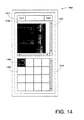
図14はソーステクスチャの操作表示1400の一例である。ソーステクスチャの操作表示1400は作業領域1402とソーステクスチャ選択スペース1404とを備える。作業領域1402はソーステクスチャ選択スペース1404から選択されたソーステクスチャを表示することができる。ソーステクスチャ選択スペース1404は、個々に異なるソーステクスチャの1または2以上の画像をサムビュー1406に表示することができる。ソーステクスチャ選択スペース1404に表示されるソーステクスチャは、テクスチャ選択コンポーネント1014(図10)を用いて選択されたソーステクスチャであってもよい。
FIG. 14 shows an example of a source
作業領域1402に示されている現在選択されているソーステクスチャを操作してソーステクスチャの変換を行うことができる。操作は、選択したソーステクスチャと関連するクリッピング矩形1408を設定するステップを含むようにしてもよい。作業領域1402の範囲内でのソーステクスチャ全体またはソーステクスチャの選択部分の拡大(ズームなど)とスクロールとを行って、ユーザがクリッピング矩形1408を正確に設定できるようにすることが可能となる。クリッピング用矩形1408を用いて、作業領域1402の範囲内でのソーステクスチャのクリッピング操作、回転操作および鏡映操作を行うことができる。ソーステクスチャ選択スペース1404内のサムビュー1406に表示されたテクスチャは、相対ポインティングデバイスまたは絶対ポインティングデバイスを用いて選択結果のドラッグ&ドロップ処理またはダブルクリックを行うことにより作業領域1402へ移動させることも可能である。
The source texture can be converted by manipulating the currently selected source texture shown in the
作業領域1402はツールバー1410を備えることも可能である。ツールバー1410はソーステクスチャの変換を行う選択ボタン(OP1〜OPnとして特定される)を備えることができる。ソーステクスチャの変換中行うことができる種々の操作処理用として選択ボタンを指定してもよい。例えば、ソーステクスチャのクリッピング、色付け、回転および鏡映の各操作をサポートするように選択ボタンを指定することができる。別の例では、特定のキーボードエントリや音声コマンドなどの種々の操作機能を作業領域1402の範囲内で呼び出す別の形の簡単なアクセスコマンドを採用してもよい。
The
ソーステクスチャに対して行われる個々の変換操作をソース変換処理手順の一部としてソーステクスチャ処理コンポーネント1016によりキャプチャし、記憶することも可能である。個々のソーステクスチャに対するソース変換処理手順を変換済みソーステクスチャと関連づけることも可能である。これに応じて、変換済みソーステクスチャを利用して複合テクスチャを形成する際、上記関連するソース変換処理手順を、複合テクスチャの形成に用いる変換処理手順の一部にしてもよい。
Individual conversion operations performed on the source texture can also be captured and stored by the source
上記ソース変換処理手順は1組の実行可能な命令であってもよい。このソース変換処理手順の中にソーステクスチャの一意のIDを含めることも可能である。したがって、変換済みの画像ではなく、ソース変換処理手順を記憶し、この処理手順にアクセスして、変換された画像を生成できることになる。プロセッサ626は、ソース変換処理手順で命令を実行することにより画像を再現してもよい。
The source conversion processing procedure may be a set of executable instructions. It is also possible to include the unique ID of the source texture in this source conversion processing procedure. Therefore, it is possible to store the source conversion processing procedure instead of the converted image and access the processing procedure to generate a converted image. The
また図10では、複合テクスチャ構成コンポーネント1018は、ユーザが1または2以上のソーステクスチャから複合テクスチャを形成できるようにする命令を出すことが可能である。ソーステクスチャのうちの1または2以上のソーステクスチャの変換を行うことにより複合テクスチャを形成することができる。複合テクスチャの形成表示を用いて複合テクスチャの形成を達成することができる。
Also in FIG. 10, composite
図15は複合テクスチャの形成表示1500の1例である。複合テクスチャが複合テクスチャの形成表示1500の例に描かれている。複合テクスチャ構成コンポーネント1018(図10)を用いて、複合テクスチャ全体または選択部分のズームとスクロールとを行うことができる。さらに、1または2以上のソーステクスチャの選択と構成とを通じて複合テクスチャ構成コンポーネント1018内の命令を開始して、複合テクスチャの形成を図ることができる。ソーステクスチャの選択と構成はソーステクスチャの変換を含むようにしてもよい。変換済みソーステクスチャは複合テクスチャの形成表示1500の際に実行される命令によってロック/ロック解除を行うことができる。所望の状態に変換済みソーステクスチャをロックして、偶然変更されるのを防ぐようにすることも可能である。
FIG. 15 shows an example of a composite
複合テクスチャ構成コンポーネント1018(図10)の範囲内の命令によって、ソーステクスチャの反復、縮尺、位置決めおよびソーティング変換をサポートするようにしてもよい。複合テクスチャ構成コンポーネント1018は、複素変換処理手順の一部として変換処理の各々をキャプチャし、記憶するようにしてもよい。複素変換処理手順は、ソーステクスチャの一意のテクスチャ識別子と、ソーステクスチャの変換を実行する命令とを同様に含むことも可能である。上記とは別に、ソーステクスチャと関連づけられるソース変換処理手順(必要な場合には)を後ろに付加することにより、複素変換処理手順を複合テクスチャと関連づけることができる。別の代替例では、追加の変換処理手順として複素変換処理手順を複合テクスチャと関連づけることができる。
Instructions within the composite texture construction component 1018 (FIG. 10) may support source texture iteration, scaling, positioning and sorting transformations. The composite
複合テクスチャ構成コンポーネント1018(図10)を用いる変換の実行は、クリッピング用矩形1408(図14)および/またはソーステクスチャ外接矩形1502を利用する複合テクスチャの編集ステップを含むようにしてもよい。ソーステクスチャ外接矩形1502を用いて変換の縮尺と位置決めの実行並びに対応する複素変換処理手順の作成を行うことができる。例示されているソーステクスチャ外接矩形1502の例と共に、コーナーの点1504と中心点1506が含まれる。水平線と垂直線とがコーナーの点1504と中心点1506との間で延伸して、ソース外接矩形1502のサイズを画定する。コーナーの点1504または中心点1506のクリックとドラッグとを行うことにより、コーナーの点1504と中心点1506とを用いてソース外接矩形1502のサイズ調整を行うことができる。ソース外接矩形1502は、互いに接触するように隣接して配置されているテクスチャの操作処理の自動化を行うことも可能である。
Performing the transformation using the composite texture construction component 1018 (FIG. 10) may include editing the composite texture using the clipping rectangle 1408 (FIG. 14) and / or the source
複合テクスチャ構成コンポーネント1018(図10)により反復とソーティングの変換処理手順を行うことができる。ツールバー1410の選択ボタンまたは複合テクスチャの形成表示1500と関連づけられる他の何らかの機能により反復変換処理手順の制御を行うことができる。反復されるソーステクスチャ間の空隙のサイズは複合テクスチャ構成コンポーネント1018を用いて変更することができる。さらに、どのソーステクスチャを第1に描くかを指示するソーティング変換処理手順は複合テクスチャ構成コンポーネント1018を用いて設定/変更を行うことができる。
The composite texture construction component 1018 (FIG. 10) can perform an iterative and sorting conversion procedure. The iterative transformation process procedure can be controlled by a selection button on the
デジタルカメラや他の画像キャプチャ装置で撮影された写真などの背景画像を下地にすることにより複合テクスチャをさらにサポートすることも可能である。背景画像を複合テクスチャと混在させずに背景に示すようにしてもよい。例えば、走査対象のビルを表わす複合テクスチャの背景に、隣接して位置するビルの前面側の画像を追えることができる。複合テクスチャを基準として上記背景画像の相対的縮尺と位置決めを同様に行うことができる。さらに、背景画像に対する複素変換処理手順を作成することも可能である。 It is also possible to further support composite textures by using a background image such as a photograph taken with a digital camera or other image capture device as a background. The background image may be shown in the background without being mixed with the composite texture. For example, an image on the front side of a building located adjacent to the background of the composite texture representing the building to be scanned can be followed. The relative scale and positioning of the background image can be similarly performed using the composite texture as a reference. Furthermore, it is possible to create a complex conversion processing procedure for the background image.
複合テクスチャの終了時に、ソース変換処理手順と複素変換処理手順とを組み合わせて、1つの変換処理手順を形成することも可能である。この変換処理手順の中に、複合テクスチャの形成に用いるすべてのソーステクスチャ用の一意のテクスチャ識別子を含めてもよい。さらに、変換処理手順は、ソーステクスチャの選択的操作を行って複合テクスチャを形成する論理命令を含むようにしてもよい。したがって、画像ファイルの形で実際の複合テクスチャを記憶する代わりに、対応する変換処理手順を一意のテクスチャ識別子に割り当て、この対応する変換処理手順をテクスチャディレクトリ1012(図10)の中で類別してもよい。 It is also possible to combine the source conversion processing procedure and the complex conversion processing procedure to form one conversion processing procedure at the end of the composite texture. In this conversion processing procedure, unique texture identifiers for all source textures used to form the composite texture may be included. Furthermore, the conversion processing procedure may include a logical instruction for selectively operating the source texture to form a composite texture. Therefore, instead of storing the actual composite texture in the form of an image file, a corresponding conversion procedure is assigned to a unique texture identifier, and the corresponding conversion procedure is categorized in the texture directory 1012 (FIG. 10). Also good.
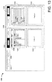
図16は、選択表示1300、ソーステクスチャの操作表示1400および複合テクスチャの形成表示1500を含むテクスチャメーカ表示1600の一例である。したがって、ソーステクスチャを特定し、変換し、操作して、単一の表示を用いて複合テクスチャを形成するようにしてもよい。別の例では、テクスチャメーカ表示1600を別様に構成したり、前述した表示の別の何らかの組み合わせを行ったりしてもよい。
FIG. 16 is an example of a
前述したテクスチャ関連処理の他に、テクスチャライジングモジュール634(図6)内の命令から追加機能を利用できるようにしてもよい。この追加機能は表示メニューやその他のユーザインタフェースから利用できるようにすることも可能である。このような機能は新たな複合テクスチャを作成する能力を含むようにしてもよい。新たな複合テクスチャの作成は、サイズ、変換処理手順およびその他の任意のテクスチャ関連情報などのテクスチャに関連するプロパティの選択ステップを含むようにしてもよい。さらに、既存の複合テクスチャの関連するプロパティのいくつかまたはすべてを利用する既存の複合テクスチャのコピーから新たなソーステクスチャを作成することも可能である。画像の形で複合テクスチャを作成する変換処理手順の実行に続いて、ソーステクスチャとして画像を記憶することも可能である。 In addition to the texture-related processing described above, an additional function may be used from an instruction in the texture rising module 634 (FIG. 6). This additional function can also be made available from the display menu and other user interfaces. Such functions may include the ability to create new composite textures. The creation of a new composite texture may include selecting a texture related property such as size, conversion procedure and any other texture related information. It is also possible to create a new source texture from a copy of an existing composite texture that utilizes some or all of the relevant properties of the existing composite texture. Following the execution of the conversion procedure that creates a composite texture in the form of an image, it is also possible to store the image as a source texture.
テクスチャライジングモジュール634の範囲内の機能はサイズの編集機能、変換処理手順および/またはテクスチャと関連づけられる他の任意の情報も含むようにしてもよい。他の情報が、例えば3次元電子モデルの前述した層内の情報を含むようにしてもよい。サイズおよびその他のプロパティはいつでも編集が可能である。追加機能はセーブ/ロード操作の実行機能、お気に入り選択機能、ツールチップおよびヘルプメニューを備えることも可能である。
Functions within the
テクスチャライジングモジュール634は、クライアント/サーバアーキテクチャの範囲内にテクスチャとライブラリ構造との同期をサポートする命令を含むようにしてもよい。テクスチャライジングモジュール634は、サーバコンピュータ上でおよび任意の台数のクライアントコンピュータ上でも処理を行うことが可能である。クライアントコンピュータのうちの1つのコンピュータを用いて、ユーザがサーバにアクセスすることも可能である。
マルチバージョンのテクスチャ構造またはライブラリ構造の作成を防止する任意の技法を用いて、ライブラリコンポーネント1004でテクスチャとライブラリ構造の保守管理を行うことも可能である。2人のユーザによってテクスチャ構造またはライブラリ構造の同時修正を行うとき、マルチバージョンを作成するようにしてもよい。マルチバージョンを避ける技法の一例にはシングルユーザ処理が含まれる。シングルユーザ処理を用いて、一人のユーザが1または2以上のテクスチャおよび/またはライブラリ構造の一部を修正しているとき、シングルユーザが修正を終了するまで、ライブラリコンポーネント1004内の命令によって別のユーザの1または2以上のテクスチャおよび/またはライブラリの一部へのアクセスを拒否するようにしてもよい。
The
上記とは別に、同期処理を実行してもよい。ライブラリコンポーネント1004内の命令によって、テクスチャライジングモジュール634内での種々のユーザの作業同期を調整するようにしてもよい。複数のユーザがテクスチャを作成し、利用するとき、ユーザはサーバを介して互いに同期をとるようにしてもよい。
Apart from the above, a synchronization process may be executed. Instructions in the
ライブラリモジュール1004(図10)内のユーザのクライアントコンピュータのローカルテクスチャ・ライブラリに個々のユーザの作業内容をローカルに記憶することも可能である。サーバは、すべてのユーザの作業内容をマスタテクスチャ・ライブラリ内に記憶する機能を持つライブラリモジュール1004を備えることも可能である。ユーザ/クライアントはクライアントコンピュータを使用してサーバと接続することができ、双方のライブラリ(マスタライブラリとローカルライブラリ)の同期が可能となる。次いで、ユーザはサーバから切断を行うことが可能となる。これによって定常な接続は存在しなくなる。本願明細書で使用されているように、“接続”という用語は、(ユーザパスワード方式などの)ログイン手続きを用いて、インターネットおよび/またはLANなどのような公衆アクセス可能なネットワークを介して、TCP/IPプロトコルを利用するネットワークなどの媒体を介してクライアントがサーバと通信を確立することを意味する。接続を形成するためのパラメータはお気に入りメニューの一部であってもよい。
It is also possible to store each user's work locally in a local texture library on the user's client computer in the library module 1004 (FIG. 10). The server can also include a
同期処理中に、個々のディレクトリおよびテクスチャと関連づけられた一意の識別子と、日付/時刻とを利用することができる。一意の識別子を用いてテクスチャディレクトリのどの部分がローカルライブラリとマスタライブラリの中で同じであるかを検出することができる。さらに、日付/時刻を用いて、どのテクスチャおよび/またはディレクトリの方がより新しいものであるかを決定することができる。 During the synchronization process, unique identifiers associated with individual directories and textures and date / time can be utilized. A unique identifier can be used to detect which part of the texture directory is the same in the local library and the master library. Furthermore, the date / time can be used to determine which texture and / or directory is newer.
例えば、マスタライブラリとローカルライブラリの双方は表2.10に示す情報を提供することができる。 For example, both the master library and the local library can provide the information shown in Table 2.10.
(表2)
次いで、第1のユーザはローカルライブラリに対する修正を行う。この修正には、一意の識別子“8E1BC531”を持つ新たなテクスチャの作成ステップが含まれ、“1238426D”として一意的に特定される既存のテクスチャの位置が変更され、さらに、表3に描かれているように“9B476CE8”と一意的に特定される別の既存のテクスチャの記述が変更される。
(Table 2)
The first user then makes modifications to the local library. This modification includes the creation of a new texture with the unique identifier “8E1BC531”, which changes the position of the existing texture uniquely identified as “1234426D” and is further depicted in Table 3 As described above, the description of another existing texture uniquely identified as “9B476CE8” is changed.
(表3)
一方、マスタライブラリは第2のユーザによりすでに更新されている。第2のユーザ2は、“175FC4EA”と一意的に特定される新たなテクスチャを持つテクスチャディレクトリを更新し、さらに、表4に例示のように“9B476CE8”として特定されるテクスチャも修正した。“9B476CE8”として特定されるテクスチャには記述に対する変更は含まれないが、代わりに、ディレクトリ位置とテクスチャの構成とが含まれる。
(Table 3)
On the other hand, the master library has already been updated by the second user. The
(表4)
第1のユーザがサーバとの接続を形成し、第1のユーザのローカルライブラリをマスタライブラリと同期させたとき、結果として生じるライブラリの変化が表5に示されている。詳細には、“8E1BC531”として特定される新規作成テクスチャが指定のディレクトリ位置に新しく追加される。さらに、“1238426D”として特定されるテクスチャは指定のディレクトリ位置へ移される。さらに、“9B476CE8”として特定されるテクスチャ(第1および第2のユーザの双方により変更されるテクスチャ)が第2のユーザが指定したディレクトリ位置に配置される。テクスチャ“9B476CE8”には、第1のユーザが行うテクスチャの構成の変更および第2のユーザが変更する新たな記述が含まれる。したがって、“9B476CE8”として特定されるテクスチャは双方の更新が混在したものとなる。
(Table 4)
Table 5 shows the resulting library changes when the first user establishes a connection with the server and synchronizes the first user's local library with the master library. Specifically, a newly created texture identified as “8E1BC531” is newly added to the designated directory location. Furthermore, the texture identified as “1234426D” is moved to the designated directory location. Further, a texture specified as “9B476CE8” (a texture that is changed by both the first and second users) is arranged at a directory position designated by the second user. The texture “9B476CE8” includes a texture configuration change made by the first user and a new description changed by the second user. Therefore, the texture specified as “9B476CE8” is a mixture of both updates.
(表5)
“9B476CE8”として特定されるテクスチャに対する複数のユーザによる更新はテクスチャライジングモジュール634により自動的に行うことができる。上記とは別に、同期処理の際、テクスチャライジングモジュール634は、第1のユーザが修正したバージョンの方がさらに最新のものであると決定することができる。さらに、テクスチャライジングモジュール634は、第1のユーザが修正したバージョンで、ディレクトリ位置とテクスチャの構成とが異なるものであることを決定することができる。さらに、テクスチャライジングモジュール634は、第1のユーザが修正したバージョンにおいて、第1のユーザがディレクトリ位置と構成とを変更しなかったことを決定するようにしてもよい。所定の条件に基づいて、テクスチャライジングモジュール634は、“9B476CE8”として特定されるテクスチャと関連づけられる不整合属性(テクスチャ、名称とディレクトリ位置)の各々に対して不整合フラグをセットしてもよい。さらに、テクスチャライジングモジュール634は第1のユーザからの命令を要求する対話ボックスを生成することも可能である。
(Table 5)
Updates by multiple users for the texture identified as “9B476CE8” can be made automatically by the
対話ボックスは不整合属性を示し、どの属性を“9B476CE8”として特定するテクスチャと関連づけた状態にしておくべきかを決定するように第1のユーザに要求することが可能となる。この時、第1のユーザは正しい属性を選択することができる。上記とは別に、第1のユーザは、同期処理を打ち切って、“9B476CE8”として特定されるテクスチャの二重化などの別の何らかのアクションを行って、別の一意のテクスチャ識別子を提供するようにしてもよい。ディレクトリに関しても同様のアクションを行うようにしてもよい。しかし、不整合ディレクトリの場合、テクスチャ名と、記述と、ディレクトリ位置のみを不整合の基礎とすることも可能である。 The dialog box shows the inconsistent attribute and can request the first user to determine which attribute should be associated with the texture identified as “9B476CE8”. At this time, the first user can select the correct attribute. Alternatively, the first user can abort the synchronization process and take some other action, such as duplexing the texture identified as “9B476CE8” to provide another unique texture identifier. Good. You may make it perform the same action regarding a directory. However, in the case of an inconsistent directory, only the texture name, description, and directory location can be used as the basis for the inconsistency.
個々のテクスチャに対する識別子の一意性を保証するために、サーバは、同期処理中、個々のユーザに1グループの未使用識別子を割り当ててもよい。このグループは所定数の一意の識別子を含むようにしてもよい。上記所定数の一意の識別子は、例えば、データを記憶するために割り当てられたメモリに基づくようにしてもよい。例えば、識別子のアドレス空間が32ビットであれば、グループのサイズは1024ビットまたはそれ以上にしてもよい。 To ensure uniqueness of identifiers for individual textures, the server may assign a group of unused identifiers to individual users during the synchronization process. This group may include a predetermined number of unique identifiers. The predetermined number of unique identifiers may be based on, for example, a memory allocated for storing data. For example, if the identifier address space is 32 bits, the group size may be 1024 bits or more.
サーバ上で作動しているテクスチャライジングモジュール634内の命令はネットワーク通信機能とサーバ管理者機能とを含むようにしてもよい。通信機能には、ユーザがクライアントコンピュータを操作してネットワークを介して接続するのを待ちながら、サーバがある特定のTCP/IPポート上で“リスニング”を行うステップが含まれる。サーバはバックグラウンドで作動していてもよく、システムトレイにアイコンを備えるようにしてもよい。アイコンのダブルクリックなどでコマンドを入力することにより、サーバ管理者は新たなライブラリを作成したり、テクスチャのロード/セーブ/バックアップ、インポートおよび/またはエクスポートを行ったり、ネットワーク通信に関連するパラメータを選択したり、ユーザ名とパスワードとを管理したりする機能を構成用対話ボックスに設けるようにしてもよい。サーバは識別子グループファイルで1グループの一意の識別子のエクスポートを行うようにしてもよい。クライアントコンピュータを使用するユーザが、ネットワークへのアクセスを行うことなく、識別子グループファイルをインポートして、クライアントコンピュータのローカルライブラリの範囲内に当該ユーザが作成したテクスチャ用の一意の識別子を提供するようにしてもよい。
The instructions in the
図17は、図1と図6に示す画像生成システム100により3次元電子モデルを形成する3次元電子画像の処理を示す部分フローチャートである。オブジェクトの走査が終了し、走査情報(3次元電子画像、関連位置情報、など)がサイト計算システム106のメモリモジュール604に記憶されると、処理はブロック1702から始まる。ブロック1704で、サイト計算システム106は、予備の位置合わせモジュール610を備えているかどうかを判定する。サイトが予備の位置合わせモジュールを備えていれば、1706で、ユーザは手動操作または自動操作を選択して走査ブロックを合成するようにしてもよい。手動操作を選択した場合、ユーザは、ブロック1708で、オブジェクトを表示しながら個々に3次元電子画像の移動と、回転とを行うことができる。ブロック1710で、ユーザは、3次元電子画像から予備用3次元電子モデルを手動で形成して、表示されているオブジェクトのマッチングを行うことができる。操作が終了したとき、ブロック1712で予備用3次元電子モデルを実験室計算システム108へ出力することができる。
FIG. 17 is a partial flowchart showing processing of a three-dimensional electronic image for forming a three-dimensional electronic model by the
ブロック1706で、自動操作を選択した場合、ブロック1716で、予備の位置合わせモジュール610内の命令を実行して、位置情報を利用し、3次元電子画像の合成と操作とを行うことができる。ブロック1718で、予備用3次元電子モデルの形成が可能となる。ブロック1720で、ユーザは追加の手動操作を希望するかどうかを決定することができる。手動操作を希望するのであれば、ブロック1708へ戻る。手動操作を希望しなければ、処理はブロック1712へ進み、予備用3次元電子モデルが実験室計算システム108へ出力される。
If automatic operation is selected at block 1706, instructions within the
図18のブロック1726で、予備用3次元電子モデルを形成する3次元電子画像に対して手動操作および/または自動操作(正確な位置合わせ)をさらに行って、走査位置間のフィットの改善が行われる。正確な位置合わせが第1の技法を含む場合、ブロック1728で、3次元電子画像のポイントクラウドが合成されて、幾何学的な点の比較を行うことによりによりモデルポイントクラウドが形成される。モデルポイントクラウドは3次元電子モデルを表わす。ブロック1730で、3次元電子モデル(モデルポイントクラウド)の表面が決定される。ブロック1732でカラー操作を行うことができる。
In
正確な位置合わせが第2の技法を含む場合、各々の3次元電子画像(ポイントクラウド)の表面がブロック1734で決定される。ブロック1736で、テクスチャが各々の3次元電子画像の表面に貼り付けられる。ブロック1738で、3次元電子画像を結合して、表面および/またはテクスチャに基づいて3次元電子モデルが形成される。ブロック1732でカラー操作を行うことができる。
If the exact alignment involves the second technique, the surface of each three-dimensional electronic image (point cloud) is determined at
正確な位置合わせが第3の技法を含む場合、ブロック1740で各々の3次元電子画像の表面が決定される。ブロック1742で個々の表面のアウトラインが決定される。3次元電子画像が結合され、ブロック1744でアウトラインに基づいて3次元電子モデルのフレームワークが形成される。ブロック1732でカラー操作を行うことができる。
If the exact registration includes a third technique, at
ブロック1748で、走査済みオブジェクトが傾斜した残りの表面上にセットされたかどうかが判定される。残りの表面が傾斜面であれば、ブロック1750で高さ補正が適用される。ブロック1752で最終3次元電子モデルが決定される。残りの表面が傾斜していなければ、ブロック1748で、処理はブロック1752へ進み、最終3次元電子モデルが決定される。
At
図17のブロック1704を再び参照すると、予備の位置合わせモジュール610が使用されなかったり、利用できなかったりする場合、個々の走査から得られる情報は、ブロック1760で実験室計算システム108へ個々に提供される。ブロック1762で、ポイントクラウドを用いて表された各々の3次元電子画像は走査合成用モジュール630によりサブイメージに分割される。ブロック1764で、サブイメージを表すラインが各々のサブイメージ用として展開される。ブロック1766で、アウトラインデータファイルにこれらのラインを個々に記憶する。次いで、ブロック1768で、アウトラインデータファイルを組み合わせ、操作して3次元電子モデルを形成する。次いで、処理は図18のブロック1730へ戻り、3次元電子モデルの形成を終了する。
Referring back to block 1704 of FIG. 17, if the
図19は、図6、8、10に例示のテクスチャライジングモジュール634を用いて3次元電子モデルをテクスチャライズする処理プロセスを示す部分フローチャートである。処理はブロック1902から始まり、3次元電子モデルの作成のために走査されるオブジェクト上に存在する1または2以上のテクスチャを表す少なくとも1つの画像ファイルがキャプチャおよび/または生成される。ブロック1904で、1または2以上のディレクトリが作成され、テクスチャディレクトリ1012内の一意の識別子によって特定される。ブロック1906で追加の属性がディレクトリに付け加えられる。ブロック1908で、キャプチャ/生成された画像ファイルを用いてソーステクスチャが形成される。ブロック1910で、ソーステクスチャカテゴリ1008内で一意の識別子を用いて個々のソーステクスチャが類別される。ブロック1912で、追加の属性がソーステクスチャに付け加えられる。
FIG. 19 is a partial flowchart illustrating a process for texturing a three-dimensional electronic model using the
ブロック1914で、第1のモードまたは第2のモードを用いてソーステクスチャを特定し、選択する。第1のモード(サーチモード)が選択された場合、ブロック1916で検索タームを入力し、サーチフィールドを選択する。ブロック1918で、結果ウインドウ1310を用いてサーチ結果を表示する。ブロック1920で、3次元電子モデル上で使用できるような表示ソーステクスチャの範囲内で利用可能なソーステクスチャが存在するかどうかが判定される。利用可能なソーステクスチャがなければ、ブロック1922で、ソーステクスチャの別のサーチを行うべきかどうかが判定される。追加のサーチをすべきでなければ、処理はブロック1902へ戻り、追加の画像ファイルのキャプチャおよび/または生成が行われる。
At
追加のサーチを行うべきであれば、処理はブロック1914へ戻り、選択モードが選択される。ブロック1920で、利用可能な表示ソーステクスチャが存在すれば、ブロック1924でソーステクスチャがサーチ結果から選択され、サムビュー1312の形で表示される。ブロック1914で第2のモード(ライブラリモード)が選択された場合、ブロック1926でテクスチャディレクトリ1012の範囲内のツリー構造がツリー構造のウインドウ1314に表示される。ブロック1928で、ユーザはツリー構造をサーチすることも可能であり、処理はブロック1920へ戻り、1または2以上の利用可能なソーステクスチャがディスプレイから特定される。
If an additional search is to be performed, processing returns to block 1914 and the selection mode is selected. If there are available display source textures at
図20で、ソーステクスチャを変換すべきかどうかがブロック1930で判定される。ソーステクスチャを変換すべきであれば、ブロック1932で、ソーステクスチャの操作表示1400を用いてソーステクスチャに対する変換処理を実行する。ブロック1934で、実行済みの変換処理をキャプチャし、ソース変換処理手順の一部とする。ブロック1936で、ソーステクスチャに対する追加の変換操作を行うべきかどうかが判定される。追加の変換を行うべきであれば処理はブロック1932へ戻る。ソーステクスチャの追加の変換を希望するのでなければ、ブロック1938で、複合テクスチャの形成表示1500の範囲内で変換済みソーステクスチャの位置決めを行って、複合テクスチャの少なくとも一部を形成するようにしてもよい。ブロック1940で、ソース変換処理手順を複合テクスチャと関連づけることができる。ブロック1942で、一意の識別子を複合テクスチャに割り当てて、複合テクスチャカテゴリ1010内で複合テクスチャの類別を行うことができる。ブロック1944で、別の属性を複合テクスチャに追加してもよい。
In FIG. 20, it is determined at
図21で、複合テクスチャの範囲内で変換済みソーステクスチャと関連する変換を所望するかどうかがブロック1946で判定される。所望するのであれば、ブロック1948で、複合テクスチャの範囲内の変換済みソーステクスチャがさらに変換される。ブロック1950で、複合テクスチャで実行した変換処理をキャプチャし、複素変換処理手順の一部とする。ブロック1952で複素変換処理手順を複合テクスチャと関連づける。
In FIG. 21, it is determined at
ブロック1954で、変換済みソーステクスチャと関連する追加の変換操作を複合テクスチャの範囲内で実行すべきかどうかが判定される。追加の変換を所望する場合、処理はブロック1948へ戻り、追加の変換操作の実行とキャプチャとが行われる。ソーステクスチャの追加の変換を所望しない場合、複合テクスチャの形成に追加ソーステクスチャが必要かどうかがブロック1956で判定される。追加ソーステクスチャが必要であれば、処理は図19のブロック1914へ戻り、別のソーステクスチャの特定と選択とが行われる。追加ソーステクスチャが必要でなければ、ブロック1958で、複合テクスチャを3次元電子モデルの1または2以上の表面と関連づけることができる。
At
ブロック1960で、テクスチャライズを行うのに3次元電子モデルの追加表面が必要かどうかが判定される。テクスチャライズを行うのに追加の表面が必要であれば、ブロック1962で3次元電子モデルおよび関連するテキスチャリゼーションが記憶される。ブロック1964で、3次元電子モデルを表すファイルはエクスポート用として利用可能となる。ブロック1960で、テクスチャライズ対象の追加表面が存在する場合、処理は、図19のブロック1914へ戻り、追加のソーステクスチャが選択される。
At
ブロック1946で、複合テクスチャの変換を所望しなければ、処理はブロック1956へ進み、追加ソーステクスチャが必要かどうかの判定が行われる。図20のブロック1930で、選択したソーステクスチャを変換するために複合テクスチャを変換しないことを所望する場合、複合テクスチャ内でソーステクスチャの位置決めを行うべきかどうかがブロック1966で判定される。複合テクスチャ内でソーステクスチャの位置決めを行うべきであれば、処理はブロック1938へ進む。複合テクスチャ内でソーステクスチャの位置決めを行わないことが望ましければ、ブロック1968でソーステクスチャは3次元電子モデルの1または2以上の表面と関連づけられ、処理はブロック1960へ進み、追加の表面をテクスチャライズする必要があるかどうかが判定される。
At
以上説明した画像生成システム100によって、テクスチャライズされ、色付けされた幾何学モデルの3次元の電子表示物の生成が可能となる。この3次元電子モデルは、1または2以上のビルなどの、ほとんど実際のオブジェクトの電子的複製とすることができる。画像生成システム100によりオブジェクトの走査を行って、3次元電子画像の作成を行うことができる。オブジェクトの電子幾何学的表示とカラーの双方を複数の走査の各々の走査で収集することができる。走査を合成して、各々の走査中に収集した位置データを用いて3次元電子モデルを形成することも可能である。画像生成システム100により3次元モデルの幾何学的表面をテクスチャライズすることによって、電子画像の表示が実際のオブジェクトの物理的表示と類似したものとなるようにすることも可能である。
The
本発明の種々の実施形態について説明したが、本発明の範囲に属するさらに多くの実施形態および実施構成が可能であることは当業者には明らかであろう。したがって、添付の請求項および上記請求項の均等物に照らして考慮する場合を除いて本発明は限定を受けるべきものではない。 While various embodiments of the invention have been described, it will be apparent to those skilled in the art that many more embodiments and implementations are possible that are within the scope of the invention. Accordingly, the invention is not to be restricted except in light of the attached claims and their equivalents.
Claims (59)
オブジェクトを走査し、スキャナ位置情報および該オブジェクトを表す画像データを提供するように動作可能なスキャナと、
該スキャナと通信する計算システムであって、該画像データおよび該スキャナ位置情報の関数として該オブジェクトの3次元電子モデルを生成するように動作可能な計算システムと
を備える、画像生成システム。 An image generation system for developing a three-dimensional electronic model of an object,
A scanner operable to scan an object and provide scanner position information and image data representing the object;
A computing system in communication with the scanner, comprising: a computing system operable to generate a three-dimensional electronic model of the object as a function of the image data and the scanner position information.
複数のそれぞれの地理的位置からの該オブジェクトの複数のそれぞれの走査の関数として、オブジェクトを表す複数のポイントクラウドを生成するように動作可能なポイントスキャナと、
該ポイントスキャナと同期して動作するカラースキャナであって、該複数のポイントクラウドの各々の該オブジェクトの色を表す色点データを生成するように動作可能なカラースキャナと、
該複数の地理的位置の各々のために、該ポイントスキャナおよびカラースキャナの位置情報を提供するように動作可能な位置システムと、
該複数のポイントクラウド、該色点データ、および該位置情報の関数として3次元電子モデルを開発するように動作可能な計算システムと
を備える、画像生成システム。 An image generation system for developing a three-dimensional electronic model of an object,
A point scanner operable to generate a plurality of point clouds representing the object as a function of a plurality of respective scans of the object from a plurality of respective geographic locations;
A color scanner that operates in synchronization with the point scanner, the color scanner operable to generate color point data representing the color of the object in each of the plurality of point clouds;
A location system operable to provide location information of the point scanner and color scanner for each of the plurality of geographic locations;
An image generation system comprising: a plurality of point clouds; the color point data; and a calculation system operable to develop a three-dimensional electronic model as a function of the position information.
オブジェクトを走査する手段であって、該オブジェクトを走査する手段の位置情報および該オブジェクトを表す画像データを決定するように動作可能な走査手段と、
該走査手段と通信する計算システムであって、該画像データおよび該位置情報の関数として該オブジェクトの3次元電子モデルを生成するように動作可能な計算システムと
を備える、画像生成システム。 An image generation system for developing a three-dimensional electronic model of an object,
Means for scanning an object, the scanning means operable to determine position information of the means for scanning the object and image data representing the object;
A computing system in communication with the scanning means, comprising: a computing system operable to generate a three-dimensional electronic model of the object as a function of the image data and the position information.
該画像生成システムは計算システムを備え、
該計算システムは、
複数のポイントクラウドを、オブジェクトを表す3次元電子モデルに組み立てる手段と、
該3次元電子モデルの複数の表面を生成する手段と、
該複数の表面をテクスチャライズする手段と、
該3次元電子モデルをテクスチャライズされた表面を用いて視覚的に描写する手段とを有する、画像生成システム。 An image generation system for developing a three-dimensional electronic model of an object,
The image generation system includes a calculation system;
The computing system is
Means for assembling a plurality of point clouds into a three-dimensional electronic model representing an object;
Means for generating a plurality of surfaces of the three-dimensional electronic model;
Means for texturing the plurality of surfaces;
Means for visually rendering the three-dimensional electronic model using a textured surface.
該複数の走査の各々は、前記複数のポイントクラウドの各々を形成する複数の幾何学的な点を含む、請求項25に記載の画像生成システム。 The computing system further comprises means for capturing a plurality of scans of the object;
26. The image generation system of claim 25, wherein each of the plurality of scans includes a plurality of geometric points forming each of the plurality of point clouds.
メモリデバイスと、
各々がオブジェクトの走査中にキャプチャされる画像データおよび位置情報を含む複数の3次元電子画像を記憶するための、該メモリデバイス内の命令と、
該複数の3次元電子画像の各々の画像データ内に含まれる複数の幾何学的な点を結合するための、該メモリデバイス内の命令と、
該位置情報の関数として3次元電子モデルを形成するために、該3次元電子画像を合成するための、該メモリデバイス内の命令と
を備える、画像生成システム。 An image generation system for developing a three-dimensional electronic model of an object,
A memory device;
Instructions in the memory device for storing a plurality of three-dimensional electronic images each including image data and position information captured during scanning of the object;
Instructions in the memory device for combining a plurality of geometric points included in image data of each of the plurality of three-dimensional electronic images;
An image generation system comprising: instructions in the memory device for synthesizing the three-dimensional electronic image to form a three-dimensional electronic model as a function of the position information.
複数の地理的位置の各々の位置内においてオブジェクトの走査を実行するステップと、
各走査中に画像データおよび位置情報を収集するステップと、
該走査中に収集された画像データおよび位置情報から、各走査を表す3次元電子画像を開発するステップと、
該オブジェクトを表す3次元電子モデルを形成するために、該位置情報の関数として複数の3次元電子を合成するステップと
を包含する、方法。 A method of developing a three-dimensional electronic model representing an object,
Performing a scan of the object within each of the plurality of geographic locations;
Collecting image data and position information during each scan;
Developing a three-dimensional electronic image representing each scan from the image data and position information collected during the scan;
Synthesizing a plurality of three-dimensional electrons as a function of the position information to form a three-dimensional electronic model representing the object.
前記3次元電子画像を開発するステップは、該オブジェクトの走査済み部分からの前記画像データを該オブジェクトの該対称的部分に鏡映するステップを包含する、請求項36に記載の方法。 The object includes a symmetric part;
37. The method of claim 36, wherein developing the three-dimensional electronic image includes mirroring the image data from the scanned portion of the object onto the symmetrical portion of the object.
各々がポイントクラウド内の複数の幾何学的な点によって表される複数の3次元電子画像をそれぞれ開発するために、スキャナを用いて複数の位置からオブジェクトを走査するステップと、
該3次元電子画像の1つを複数のサブ画像内に位置決めするステップと、
該複数の幾何学的な点をそれぞれの該サブ画像を示す複数のラインに変換するステップと、
3次元電子モデルを開発するために、該ラインを合成するステップと
を包含する、方法。 A method of developing a three-dimensional electronic model representing an object,
Scanning an object from a plurality of positions with a scanner to develop a plurality of three-dimensional electronic images each represented by a plurality of geometric points in a point cloud;
Positioning one of the three-dimensional electronic images within a plurality of sub-images;
Converting the plurality of geometric points into a plurality of lines representing each of the sub-images;
Synthesizing the line to develop a three-dimensional electronic model.
オブジェクトの複数の走査をキャプチャするステップであって、該走査の各々は、3次元電子画像を表す画像データと、各走査がキャプチャされた位置を示す位置情報とを含む、ステップと、
該走査を合成することによって、該位置情報の関数として該オブジェクトの3次元電子モデルを形成するステップと、
ソーステクスチャの関数として該3次元電子モデルをテクスチャライズするステップと
を包含する、方法。 A method of developing a three-dimensional electronic model representing an object,
Capturing a plurality of scans of an object, each of the scans including image data representing a three-dimensional electronic image and position information indicating the position at which each scan was captured;
Synthesizing the scan to form a three-dimensional electronic model of the object as a function of the position information;
Texturing the three-dimensional electronic model as a function of source texture.
Applications Claiming Priority (2)
| Application Number | Priority Date | Filing Date | Title |
|---|---|---|---|
| US39516502P | 2002-07-10 | 2002-07-10 | |
| PCT/US2003/020225 WO2004006181A2 (en) | 2002-07-10 | 2003-06-30 | System for generating three-dimensional electronic models of objects |
Publications (1)
| Publication Number | Publication Date |
|---|---|
| JP2005537535A true JP2005537535A (en) | 2005-12-08 |
Family
ID=30115826
Family Applications (4)
| Application Number | Title | Priority Date | Filing Date |
|---|---|---|---|
| JP2004519655A Withdrawn JP2005532631A (en) | 2002-07-10 | 2003-06-30 | System for texture rising of electronic display objects |
| JP2004519656A Pending JP2005537535A (en) | 2002-07-10 | 2003-06-30 | System for generating a 3D electronic model of an object |
| JP2008183229A Expired - Fee Related JP4685905B2 (en) | 2002-07-10 | 2008-07-14 | System for texture rising of electronic display objects |
| JP2010164363A Expired - Lifetime JP5105643B2 (en) | 2002-07-10 | 2010-07-21 | System for texture rising of electronic display objects |
Family Applications Before (1)
| Application Number | Title | Priority Date | Filing Date |
|---|---|---|---|
| JP2004519655A Withdrawn JP2005532631A (en) | 2002-07-10 | 2003-06-30 | System for texture rising of electronic display objects |
Family Applications After (2)
| Application Number | Title | Priority Date | Filing Date |
|---|---|---|---|
| JP2008183229A Expired - Fee Related JP4685905B2 (en) | 2002-07-10 | 2008-07-14 | System for texture rising of electronic display objects |
| JP2010164363A Expired - Lifetime JP5105643B2 (en) | 2002-07-10 | 2010-07-21 | System for texture rising of electronic display objects |
Country Status (8)
| Country | Link |
|---|---|
| US (3) | US7643669B2 (en) |
| EP (2) | EP1556823B1 (en) |
| JP (4) | JP2005532631A (en) |
| KR (2) | KR100660351B1 (en) |
| CN (2) | CN100578525C (en) |
| AU (2) | AU2003245715A1 (en) |
| CA (2) | CA2489364C (en) |
| WO (2) | WO2004006180A2 (en) |
Families Citing this family (132)
| Publication number | Priority date | Publication date | Assignee | Title |
|---|---|---|---|---|
| US7756721B1 (en) * | 1997-03-14 | 2010-07-13 | Best Doctors, Inc. | Health care management system |
| EP1662228A1 (en) | 2004-11-19 | 2006-05-31 | Harman Becker Automotive Systems GmbH | Scanning of three-dimensional objects |
| CA2489364C (en) * | 2002-07-10 | 2010-06-01 | Harman Becker Automotive Systems Gmbh | System for generating three-dimensional electronic models of objects |
| JP2007535267A (en) * | 2004-04-29 | 2007-11-29 | コーニンクレッカ フィリップス エレクトロニクス エヌ ヴィ | Image processing apparatus and method |
| EP1754197A1 (en) * | 2004-06-08 | 2007-02-21 | Three-B International Limited | Displaying graphical textures |
| DE102004030876A1 (en) * | 2004-06-25 | 2006-02-02 | Grüntjens, Norbert | Method for generating a realistic representation |
| CN1866264A (en) * | 2005-05-21 | 2006-11-22 | 华为技术有限公司 | Scene generating method and system for mobile game |
| US7705863B2 (en) * | 2005-11-15 | 2010-04-27 | Honeywell International Inc. | Systems and methods for rendering building spaces |
| US8494805B2 (en) | 2005-11-28 | 2013-07-23 | Orthosensor | Method and system for assessing orthopedic alignment using tracking sensors |
| US8000926B2 (en) * | 2005-11-28 | 2011-08-16 | Orthosensor | Method and system for positional measurement using ultrasonic sensing |
| US8098544B2 (en) | 2005-11-29 | 2012-01-17 | Orthosensor, Inc. | Method and system for enhancing accuracy in ultrasonic alignment |
| US8814810B2 (en) * | 2005-12-01 | 2014-08-26 | Orthosensor Inc. | Orthopedic method and system for mapping an anatomical pivot point |
| US8864686B2 (en) * | 2005-12-01 | 2014-10-21 | Orthosensor Inc. | Virtual mapping of an anatomical pivot point and alignment therewith |
| US8421642B1 (en) | 2006-08-24 | 2013-04-16 | Navisense | System and method for sensorized user interface |
| US8638296B1 (en) | 2006-09-05 | 2014-01-28 | Jason McIntosh | Method and machine for navigation system calibration |
| JP5073256B2 (en) * | 2006-09-22 | 2012-11-14 | 株式会社トプコン | POSITION MEASUREMENT DEVICE, POSITION MEASUREMENT METHOD, AND POSITION MEASUREMENT PROGRAM |
| JP5057734B2 (en) | 2006-09-25 | 2012-10-24 | 株式会社トプコン | Surveying method, surveying system, and surveying data processing program |
| EP1912176B1 (en) * | 2006-10-09 | 2009-01-07 | Harman Becker Automotive Systems GmbH | Realistic height representation of streets in digital maps |
| WO2008044913A1 (en) * | 2006-10-13 | 2008-04-17 | Tele Atlas B.V. | System for and method of processing laser scan samples and digital photographic images relating to building façade |
| EP2503475A1 (en) * | 2006-12-19 | 2012-09-26 | Swisscom AG | Method and device for selective access to data elements in a data set |
| PE20120627A1 (en) * | 2006-12-20 | 2012-05-26 | Scanalyse Pty Ltd | SYSTEM FOR MEASURING THE DISPLACEMENT OF A SURFACE RELATIVE TO A REFERENCE BASE |
| CN101617197B (en) | 2007-02-16 | 2011-06-22 | 三菱电机株式会社 | Feature identification apparatus, measurement apparatus and measuring method |
| US8190400B1 (en) * | 2007-03-16 | 2012-05-29 | The Mathworks, Inc. | Thin client graphical presentation and manipulation application |
| US20080275732A1 (en) * | 2007-05-01 | 2008-11-06 | Best Doctors, Inc. | Using patterns of medical treatment codes to determine when further medical expertise is called for |
| US8224098B2 (en) * | 2007-06-15 | 2012-07-17 | Microsoft Corporation | Façade rendering system |
| US20090027417A1 (en) * | 2007-07-24 | 2009-01-29 | Horsfall Joseph B | Method and apparatus for registration and overlay of sensor imagery onto synthetic terrain |
| CN101387506B (en) * | 2007-09-14 | 2010-11-10 | 鸿富锦精密工业(深圳)有限公司 | Point cloud optimum alignment method |
| ATE514055T1 (en) * | 2007-11-07 | 2011-07-15 | Tele Atlas Bv | COMPUTER ARRANGEMENT AND METHOD FOR COMPUTING MOTION VECTORS USING DISTANCE DATA |
| US8531472B2 (en) * | 2007-12-03 | 2013-09-10 | Pictometry International Corp. | Systems and methods for rapid three-dimensional modeling with real façade texture |
| US9189083B2 (en) | 2008-03-18 | 2015-11-17 | Orthosensor Inc. | Method and system for media presentation during operative workflow |
| US9892485B2 (en) * | 2008-04-08 | 2018-02-13 | Disney Enterprises, Inc. | System and method for mesh distance based geometry deformation |
| WO2009131361A2 (en) * | 2008-04-22 | 2009-10-29 | 팅크웨어(주) | Apparatus and method for editing map data in a 3-dimensional map service |
| WO2009131277A1 (en) * | 2008-04-24 | 2009-10-29 | Thinkware Systems Corporation | System and method for displaying three-dimensional map using template modeling |
| US8737721B2 (en) * | 2008-05-07 | 2014-05-27 | Microsoft Corporation | Procedural authoring |
| KR100888155B1 (en) * | 2008-05-14 | 2009-03-10 | 팅크웨어(주) | System and method for displaying 3-dimension map using texture mapping |
| US7778788B2 (en) * | 2008-05-29 | 2010-08-17 | United Technologies Corporation | Scanner based optical inspection system |
| US7987262B2 (en) | 2008-11-19 | 2011-07-26 | Accenture Global Services Limited | Cloud computing assessment tool |
| CN101750030B (en) * | 2008-12-17 | 2012-11-21 | 鸿富锦精密工业(深圳)有限公司 | Curved surface detecting system and method |
| JP5688876B2 (en) * | 2008-12-25 | 2015-03-25 | 株式会社トプコン | Calibration method for laser scanner measurement system |
| US20100262508A1 (en) * | 2009-04-10 | 2010-10-14 | Will Volnak | Method and system for an online library marketplace |
| CN101871767B (en) * | 2009-04-25 | 2012-05-30 | 鸿富锦精密工业(深圳)有限公司 | System and method for detecting form and position tolerance of components |
| KR101396373B1 (en) * | 2009-05-28 | 2014-05-19 | 켄트 디스플레이스 인코포레이티드 | Writing tablet information recording device |
| US8355541B2 (en) * | 2009-07-14 | 2013-01-15 | Empire Technology Development Llc | Texture sensing |
| US8872823B2 (en) * | 2009-10-09 | 2014-10-28 | Microsoft Corporation | Automatic real-time shader modification for texture fetch instrumentation |
| US9582919B2 (en) * | 2009-10-09 | 2017-02-28 | Microsoft Technology Licensing, Llc | Automatic run-time identification of textures |
| AU2015275308B2 (en) * | 2009-10-26 | 2018-03-08 | Pictometry International Corp. | A method for automatic material classification and texture simulation for 3d models |
| US9330494B2 (en) * | 2009-10-26 | 2016-05-03 | Pictometry International Corp. | Method for the automatic material classification and texture simulation for 3D models |
| WO2011079241A1 (en) * | 2009-12-23 | 2011-06-30 | Tomtom International Bv | Method of generating building facade data for a geospatial database for a mobile device |
| US9011448B2 (en) * | 2009-12-31 | 2015-04-21 | Orthosensor Inc. | Orthopedic navigation system with sensorized devices |
| WO2011091552A1 (en) * | 2010-02-01 | 2011-08-04 | Intel Corporation | Extracting and mapping three dimensional features from geo-referenced images |
| JP5551245B2 (en) | 2010-03-19 | 2014-07-16 | 株式会社日立製作所 | File sharing system, file processing method, and program |
| EP2569595B1 (en) * | 2010-05-12 | 2018-07-04 | Leica Geosystems AG | Surveying instrument |
| JP5912234B2 (en) | 2010-07-16 | 2016-04-27 | 株式会社トプコン | measuring device |
| JP5698480B2 (en) | 2010-09-02 | 2015-04-08 | 株式会社トプコン | Measuring method and measuring device |
| JP5653715B2 (en) | 2010-10-27 | 2015-01-14 | 株式会社トプコン | Laser surveyor |
| US8939369B2 (en) | 2011-01-24 | 2015-01-27 | Datalogic ADC, Inc. | Exception detection and handling in automated optical code reading systems |
| JP5753409B2 (en) | 2011-03-07 | 2015-07-22 | 株式会社トプコン | Panorama image creation method and three-dimensional laser scanner |
| US9151608B2 (en) * | 2011-03-31 | 2015-10-06 | Francis Ruben Malka | Apparatus, tool, and method for modifying a portion of a floor plan based on measurements made by one or more sensors |
| US9361479B2 (en) | 2011-04-29 | 2016-06-07 | Stephen Lesavich | Method and system for electronic content storage and retrieval using Galois fields and geometric shapes on cloud computing networks |
| US9569771B2 (en) | 2011-04-29 | 2017-02-14 | Stephen Lesavich | Method and system for storage and retrieval of blockchain blocks using galois fields |
| JP5887715B2 (en) * | 2011-05-23 | 2016-03-16 | セイコーエプソン株式会社 | Image processing apparatus and image processing method |
| WO2012168322A2 (en) * | 2011-06-06 | 2012-12-13 | 3Shape A/S | Dual-resolution 3d scanner |
| JP4855547B1 (en) * | 2011-06-30 | 2012-01-18 | 日本ジタン株式会社 | Method for analyzing the configuration of stereotyped bodies |
| US8994726B1 (en) | 2011-12-30 | 2015-03-31 | Google Inc. | Systems and methods for preparing a model of an environment for display |
| US8994725B1 (en) * | 2011-12-30 | 2015-03-31 | Google Inc. | Systems and methods for generating a model of an environment |
| US9501700B2 (en) | 2012-02-15 | 2016-11-22 | Xactware Solutions, Inc. | System and method for construction estimation using aerial images |
| DE102013102286A1 (en) * | 2012-07-03 | 2014-01-09 | Zoller & Fröhlich GmbH | Method and device for evaluating laser scans |
| KR102162952B1 (en) * | 2012-09-18 | 2020-10-07 | 씽크 써지컬, 인크. | System and method for registration in orthopaedic applications |
| US10067231B2 (en) | 2012-10-05 | 2018-09-04 | Faro Technologies, Inc. | Registration calculation of three-dimensional scanner data performed between scans based on measurements by two-dimensional scanner |
| DE102012109481A1 (en) * | 2012-10-05 | 2014-04-10 | Faro Technologies, Inc. | Device for optically scanning and measuring an environment |
| US10674135B2 (en) * | 2012-10-17 | 2020-06-02 | DotProduct LLC | Handheld portable optical scanner and method of using |
| US9332243B2 (en) * | 2012-10-17 | 2016-05-03 | DotProduct LLC | Handheld portable optical scanner and method of using |
| EP2787322B1 (en) * | 2013-04-05 | 2017-10-04 | Leica Geosystems AG | Georeferencing of point clouds |
| EP2787321B1 (en) * | 2013-04-05 | 2015-09-16 | Leica Geosystems AG | Surface determination for objects using precise geodesic point determination and scanning |
| US9651525B2 (en) | 2013-06-27 | 2017-05-16 | TecScan Systems Inc. | Method and apparatus for scanning an object |
| EP3028464B1 (en) | 2013-08-02 | 2019-05-01 | Xactware Solutions Inc. | System and method for detecting features in aerial images using disparity mapping and segmentation techniques |
| DE102013017500B3 (en) * | 2013-10-17 | 2015-04-02 | Faro Technologies, Inc. | Method and apparatus for optically scanning and measuring a scene |
| US10203399B2 (en) | 2013-11-12 | 2019-02-12 | Big Sky Financial Corporation | Methods and apparatus for array based LiDAR systems with reduced interference |
| US9911205B1 (en) * | 2014-03-14 | 2018-03-06 | Google Llc | Visual continuity for arbitrary length stipple patterns |
| DE102014104713A1 (en) | 2014-04-02 | 2015-10-08 | Faro Technologies, Inc. | Register a clustered scene with pairs of scans |
| DE102014104712B4 (en) * | 2014-04-02 | 2020-07-30 | Faro Technologies, Inc. | Registration of a scene disintegrating into clusters with visualized clusters |
| US9360554B2 (en) | 2014-04-11 | 2016-06-07 | Facet Technology Corp. | Methods and apparatus for object detection and identification in a multiple detector lidar array |
| DE102014110992A1 (en) | 2014-08-01 | 2016-02-04 | Faro Technologies Inc. | Register a clustered scene with location tracking |
| JP6305912B2 (en) * | 2014-12-17 | 2018-04-04 | 株式会社ジオ技術研究所 | Texture generation system |
| EP3872525A1 (en) | 2015-02-13 | 2021-09-01 | Zoller & Fröhlich GmbH | Scanning assembly and method for scanning an object |
| US9665989B1 (en) * | 2015-02-17 | 2017-05-30 | Google Inc. | Feature agnostic geometric alignment |
| US10036801B2 (en) | 2015-03-05 | 2018-07-31 | Big Sky Financial Corporation | Methods and apparatus for increased precision and improved range in a multiple detector LiDAR array |
| US10175360B2 (en) | 2015-03-31 | 2019-01-08 | Faro Technologies, Inc. | Mobile three-dimensional measuring instrument |
| EP3257026B1 (en) * | 2015-06-04 | 2020-11-18 | Hewlett-Packard Development Company, L.P. | Generating three dimensional models |
| WO2016197251A1 (en) * | 2015-06-11 | 2016-12-15 | Queen's University At Kingston | Automated mobile geotechnical mapping |
| EP3329211A4 (en) * | 2015-07-31 | 2019-03-06 | Hewlett-Packard Development Company, L.P. | Turntable peripheral for 3d scanning |
| CN108140066B (en) * | 2015-10-01 | 2022-02-15 | 富士胶片株式会社 | Drawing making device and drawing making method |
| US9905040B2 (en) | 2016-02-08 | 2018-02-27 | Apple Inc. | Texture sampling techniques |
| US9866816B2 (en) | 2016-03-03 | 2018-01-09 | 4D Intellectual Properties, Llc | Methods and apparatus for an active pulsed 4D camera for image acquisition and analysis |
| US11573325B2 (en) * | 2016-03-11 | 2023-02-07 | Kaarta, Inc. | Systems and methods for improvements in scanning and mapping |
| EP3427008B1 (en) | 2016-03-11 | 2022-09-07 | Kaarta, Inc. | Laser scanner with real-time, online ego-motion estimation |
| CN105957133B (en) | 2016-05-10 | 2018-06-05 | 网易(杭州)网络有限公司 | A kind of method and apparatus for loading textures |
| WO2017199088A1 (en) * | 2016-05-19 | 2017-11-23 | Vermeer International B.V. | Bale detection and classification using stereo cameras |
| CN106023322A (en) * | 2016-05-27 | 2016-10-12 | 美屋三六五(天津)科技有限公司 | Three-dimensional model processing method and apparatus |
| CN106056666B (en) * | 2016-05-27 | 2019-03-29 | 美屋三六五(天津)科技有限公司 | A kind of threedimensional model processing method and system |
| CN106067185A (en) * | 2016-05-27 | 2016-11-02 | 美屋三六五(天津)科技有限公司 | A kind of threedimensional model processing method and processing device |
| CN106067184A (en) * | 2016-05-27 | 2016-11-02 | 美屋三六五(天津)科技有限公司 | A kind of threedimensional model processing method and processing device |
| GB2555199B (en) | 2016-08-19 | 2022-03-16 | Faro Tech Inc | Using a two-dimensional scanner to speed registration of three-dimensional scan data |
| US10380749B2 (en) | 2016-09-26 | 2019-08-13 | Faro Technologies, Inc. | Device and method for indoor mobile mapping of an environment |
| US10282854B2 (en) | 2016-10-12 | 2019-05-07 | Faro Technologies, Inc. | Two-dimensional mapping system and method of operation |
| US11040491B2 (en) * | 2016-10-19 | 2021-06-22 | Shapeways, Inc. | Systems and methods for identifying three-dimensional printed objects |
| EP3330924A1 (en) * | 2016-12-01 | 2018-06-06 | Thomson Licensing | Method for 3d reconstruction of an environment of a mobile device, corresponding computer program product and device |
| US10824773B2 (en) | 2017-03-28 | 2020-11-03 | Faro Technologies, Inc. | System and method of scanning an environment and generating two dimensional images of the environment |
| CN108664177B (en) * | 2017-03-29 | 2021-11-12 | 上海耕岩智能科技有限公司 | Method and device for opening application based on fingerprint identification |
| CN108664850B (en) * | 2017-03-30 | 2021-07-13 | 展讯通信(上海)有限公司 | Human face posture classification method and device |
| CN107463398B (en) * | 2017-07-21 | 2018-08-17 | 腾讯科技(深圳)有限公司 | Game rendering intent, device, storage device and terminal |
| WO2019099605A1 (en) | 2017-11-17 | 2019-05-23 | Kaarta, Inc. | Methods and systems for geo-referencing mapping systems |
| US10928196B2 (en) | 2017-12-28 | 2021-02-23 | Topcon Positioning Systems, Inc. | Vision laser receiver |
| KR102178835B1 (en) * | 2018-03-28 | 2020-11-13 | (주)로딕스 | Apparatus and method for data management for reconstruct in 3d object surface |
| US11055532B2 (en) | 2018-05-02 | 2021-07-06 | Faro Technologies, Inc. | System and method of representing and tracking time-based information in two-dimensional building documentation |
| CN108765566A (en) * | 2018-05-21 | 2018-11-06 | 瞪羚实训(北京)科技有限公司 | Image processing method and device, storage medium, 3D modeling system and method |
| WO2020009826A1 (en) * | 2018-07-05 | 2020-01-09 | Kaarta, Inc. | Methods and systems for auto-leveling of point clouds and 3d models |
| GB2571382B (en) * | 2018-07-27 | 2020-02-19 | Sony Interactive Entertainment Inc | A parallel method of flood filing, and apparatus |
| AU2019355489A1 (en) | 2018-10-02 | 2021-04-15 | Panasonic Intellectual Property Corporation Of America | Three-dimensional data encoding method, three-dimensional data decoding method, three-dimensional data encoding device, and three-dimensional data decoding device |
| CA3115280A1 (en) * | 2018-10-04 | 2020-04-09 | Geomni, Inc. | Computer vision systems and methods for identifying anomalies in building models |
| CN109300189A (en) * | 2018-10-26 | 2019-02-01 | 五维智能信息科技(北京)有限公司 | A kind of object dimensional model building method and device |
| US11024050B2 (en) | 2018-11-05 | 2021-06-01 | Faro Technologies, Inc. | System and method of scanning an environment |
| US10909686B2 (en) * | 2018-11-28 | 2021-02-02 | International Business Machines Corporation | Identifying and extracting a sub-image in a document image file |
| US11486701B2 (en) | 2019-02-06 | 2022-11-01 | Faro Technologies, Inc. | System and method for performing a real-time wall detection |
| TWI731400B (en) * | 2019-08-30 | 2021-06-21 | 潤弘精密工程事業股份有限公司 | Method and system for processing building information modeling data |
| US10891766B1 (en) * | 2019-09-04 | 2021-01-12 | Google Llc | Artistic representation of digital data |
| US11094113B2 (en) | 2019-12-04 | 2021-08-17 | Geomni, Inc. | Systems and methods for modeling structures using point clouds derived from stereoscopic image pairs |
| US11501478B2 (en) | 2020-08-17 | 2022-11-15 | Faro Technologies, Inc. | System and method of automatic room segmentation for two-dimensional laser floorplans |
| US20220244833A1 (en) * | 2021-01-22 | 2022-08-04 | Primitive LLC | Interactive 3d roof model |
| US11717967B2 (en) | 2021-03-04 | 2023-08-08 | TecScan Systems Inc. | System and method for scanning an object using an array of ultrasonic transducers |
| CN114858087A (en) * | 2022-03-25 | 2022-08-05 | 先临三维科技股份有限公司 | Mobile computing module for three-dimensional scanner, three-dimensional scanning method and device |
| US20240069203A1 (en) * | 2022-08-31 | 2024-02-29 | Faro Technologies, Inc. | Global optimization methods for mobile coordinate scanners |
Family Cites Families (36)
| Publication number | Priority date | Publication date | Assignee | Title |
|---|---|---|---|---|
| JPH0378095A (en) | 1989-08-21 | 1991-04-03 | Daikin Ind Ltd | Method and device for shading-out edge emphasizing polygon |
| US5194969A (en) * | 1990-12-04 | 1993-03-16 | Pixar | Method for borderless mapping of texture images |
| US5471572A (en) * | 1993-07-09 | 1995-11-28 | Silicon Graphics, Inc. | System and method for adding detail to texture imagery in computer generated interactive graphics |
| US5566073A (en) * | 1994-07-11 | 1996-10-15 | Margolin; Jed | Pilot aid using a synthetic environment |
| US5802361A (en) * | 1994-09-30 | 1998-09-01 | Apple Computer, Inc. | Method and system for searching graphic images and videos |
| JP3541855B2 (en) | 1994-12-01 | 2004-07-14 | 朝日航洋株式会社 | Method and apparatus for extracting three-dimensional data |
| JPH0997344A (en) * | 1995-09-29 | 1997-04-08 | Fujitsu Ltd | Method and system for texture generation |
| JPH09102029A (en) | 1995-10-09 | 1997-04-15 | Oki Electric Ind Co Ltd | Topography data interpolation device |
| JPH09138870A (en) * | 1995-11-15 | 1997-05-27 | Canon Inc | Picture processor and picture processing method |
| US6285373B1 (en) * | 1996-03-29 | 2001-09-04 | 3Dlabs Inc. Ltd. | Method and apparatus for texture transmission and storage |
| US5988862A (en) | 1996-04-24 | 1999-11-23 | Cyra Technologies, Inc. | Integrated system for quickly and accurately imaging and modeling three dimensional objects |
| JPH1091760A (en) | 1996-09-13 | 1998-04-10 | Oki Electric Ind Co Ltd | Three-dimensional topography output method and device and recording medium |
| JP3503385B2 (en) | 1997-01-20 | 2004-03-02 | 日産自動車株式会社 | Navigation system and medium storing navigation program used therein |
| DE19801801C2 (en) | 1997-01-20 | 2000-06-29 | Nissan Motor | Navigation system and storage medium for storing operating programs used for it |
| JPH10275246A (en) | 1997-03-31 | 1998-10-13 | Intec:Kk | Three-dimensional computer graphic system |
| US20020154132A1 (en) | 1997-07-30 | 2002-10-24 | Alain M. Dumesny | Texture mapping 3d graphic objects |
| JP3162664B2 (en) | 1997-10-09 | 2001-05-08 | 株式会社シーエスケイ | Method and apparatus for creating three-dimensional cityscape information |
| US6522336B1 (en) * | 1997-10-31 | 2003-02-18 | Hewlett-Packard Company | Three-dimensional graphics rendering apparatus and method |
| JP3971003B2 (en) | 1997-12-17 | 2007-09-05 | 株式会社コナミデジタルエンタテインメント | Image creation device |
| JP3672739B2 (en) | 1998-06-29 | 2005-07-20 | 富士通株式会社 | Texture image generator |
| US6480538B1 (en) * | 1998-07-08 | 2002-11-12 | Koninklijke Philips Electronics N.V. | Low bandwidth encoding scheme for video transmission |
| US6600553B1 (en) * | 1998-11-03 | 2003-07-29 | National Institute Of Science And Technology U.S. Dept Of Commerce | Three degree-of-freedom telescoping geometry scanner |
| JP3614709B2 (en) | 1999-05-20 | 2005-01-26 | 日本電信電話株式会社 | Landscape image index method, apparatus, and recording medium recording landscape image index program |
| JP2001043394A (en) | 1999-08-03 | 2001-02-16 | Dainippon Printing Co Ltd | Image display method and device |
| DE19948544A1 (en) * | 1999-10-08 | 2001-05-10 | Gta Geoinformatik Gmbh | Terrestrial digital photogrammetry device for digital detection of spatial scene, has control computer which stores image data resulting from image pick-up together with orientation and angle data in memory |
| JP4438971B2 (en) | 1999-10-20 | 2010-03-24 | グンゼ株式会社 | Data three-dimensional apparatus and computer-readable recording medium recording data three-dimensional program |
| JP4372283B2 (en) | 1999-10-20 | 2009-11-25 | グンゼ株式会社 | Computer-readable recording medium recording design support apparatus and design support program |
| FI112402B (en) | 1999-10-28 | 2003-11-28 | Diware Oy | Method for determining the characteristics of tree stocks and computer programs for performing the procedure |
| US6466162B2 (en) | 2000-02-16 | 2002-10-15 | Bertho Boman | System and method for measuring distance between two objects |
| US7728848B2 (en) * | 2000-03-28 | 2010-06-01 | DG FastChannel, Inc. | Tools for 3D mesh and texture manipulation |
| US20010048443A1 (en) * | 2000-04-17 | 2001-12-06 | Jeffrey Burrell | Method and system for changing the display of one texture to another in a computer graphics system |
| JP3384557B2 (en) | 2000-05-18 | 2003-03-10 | 国際航業株式会社 | Three-dimensional topographic map creation method and system, and recording medium |
| US6664529B2 (en) | 2000-07-19 | 2003-12-16 | Utah State University | 3D multispectral lidar |
| JP4487400B2 (en) * | 2000-09-08 | 2010-06-23 | ソニー株式会社 | Image deformation apparatus and image deformation method |
| JP3823724B2 (en) | 2000-12-14 | 2006-09-20 | 日本電気株式会社 | Three-dimensional aerial sightseeing improvement server, method thereof, and recording medium |
| CA2489364C (en) * | 2002-07-10 | 2010-06-01 | Harman Becker Automotive Systems Gmbh | System for generating three-dimensional electronic models of objects |
-
2003
- 2003-06-30 CA CA2489364A patent/CA2489364C/en not_active Expired - Lifetime
- 2003-06-30 CA CA2489200A patent/CA2489200C/en not_active Expired - Fee Related
- 2003-06-30 KR KR1020057000483A patent/KR100660351B1/en active IP Right Grant
- 2003-06-30 KR KR1020057000485A patent/KR100656238B1/en active IP Right Grant
- 2003-06-30 US US10/519,252 patent/US7643669B2/en active Active
- 2003-06-30 WO PCT/US2003/020224 patent/WO2004006180A2/en active Application Filing
- 2003-06-30 EP EP03739329.5A patent/EP1556823B1/en not_active Expired - Lifetime
- 2003-06-30 EP EP03739328A patent/EP1520268A4/en not_active Ceased
- 2003-06-30 JP JP2004519655A patent/JP2005532631A/en not_active Withdrawn
- 2003-06-30 CN CN03816377A patent/CN100578525C/en not_active Expired - Lifetime
- 2003-06-30 CN CN038163810A patent/CN1669069B/en not_active Expired - Fee Related
- 2003-06-30 AU AU2003245715A patent/AU2003245715A1/en not_active Abandoned
- 2003-06-30 JP JP2004519656A patent/JP2005537535A/en active Pending
- 2003-06-30 US US10/519,223 patent/US7561165B2/en not_active Expired - Lifetime
- 2003-06-30 WO PCT/US2003/020225 patent/WO2004006181A2/en active Application Filing
- 2003-06-30 AU AU2003245713A patent/AU2003245713A1/en not_active Abandoned
-
2005
- 2005-11-21 US US11/284,803 patent/US7689032B2/en active Active
-
2008
- 2008-07-14 JP JP2008183229A patent/JP4685905B2/en not_active Expired - Fee Related
-
2010
- 2010-07-21 JP JP2010164363A patent/JP5105643B2/en not_active Expired - Lifetime
Also Published As
Similar Documents
| Publication | Publication Date | Title |
|---|---|---|
| JP5105643B2 (en) | System for texture rising of electronic display objects | |
| Kadobayashi et al. | Comparison and evaluation of laser scanning and photogrammetry and their combined use for digital recording of cultural heritage | |
| Cosmas et al. | 3D MURALE: A multimedia system for archaeology | |
| Hanke et al. | Architectural photogrammetry: Basic theory, procedures, tools | |
| CN105678701A (en) | An archaeological excavation unit sequence three-dimensional visualization method based on multi-view images and laser scanning | |
| US10740870B2 (en) | Creating a floor plan from images in spherical format | |
| Bolkas et al. | Creating a virtual reality environment with a fusion of sUAS and TLS point-clouds | |
| Grussenmeyer et al. | 4.1 ARCHITECTURAL PHOTOGRAMMETRY | |
| Rüther et al. | Challenges in heritage documentation with terrestrial laser scanning | |
| Ragia et al. | Precise photorealistic visualization for restoration of historic buildings based on tacheometry data | |
| US10529055B1 (en) | Compensating for camera pose in a spherical image | |
| Lerma et al. | Three‐Dimensional city model visualisation for real‐time guided museum tours | |
| Karsli et al. | Building 3D photo-texture model integrated with GIS for architectural heritage conservation | |
| Cosmas et al. | A novel multimedia system for archaeology | |
| Simonetto et al. | Valorisation of Cultural Heritage Through Virtual Visit and Augmented Reality: The Case of the Abbey of Epau (France) | |
| Ab et al. | Three Dimensional Modelling of Building using Faro Laser Scanner And AUTOCAD 2011 Software | |
| Bitelli et al. | Close-range Photogrammetry, virtual reality and their integration in Archaeology | |
| Wendt et al. | Image-based modelling of architectural sites: the iWitness approach | |
| Green et al. | A distributed universal 3d cyberworld for archaeological research and education | |
| Leberl | Models and visualizations in a virtual habitat | |
| Colombo et al. | New Experiences, Remarks and Prospects: Building Reconstruction and Texturing |
Legal Events
| Date | Code | Title | Description |
|---|---|---|---|
| A131 | Notification of reasons for refusal |
Free format text: JAPANESE INTERMEDIATE CODE: A131 Effective date: 20071207 |
|
| A521 | Request for written amendment filed |
Free format text: JAPANESE INTERMEDIATE CODE: A523 Effective date: 20080307 |
|
| A02 | Decision of refusal |
Free format text: JAPANESE INTERMEDIATE CODE: A02 Effective date: 20080403 |
|
| A521 | Request for written amendment filed |
Free format text: JAPANESE INTERMEDIATE CODE: A523 Effective date: 20080801 |
|
| A911 | Transfer to examiner for re-examination before appeal (zenchi) |
Free format text: JAPANESE INTERMEDIATE CODE: A911 Effective date: 20080811 |
|
| A912 | Re-examination (zenchi) completed and case transferred to appeal board |
Free format text: JAPANESE INTERMEDIATE CODE: A912 Effective date: 20080905 |
|
| A601 | Written request for extension of time |
Free format text: JAPANESE INTERMEDIATE CODE: A601 Effective date: 20091007 |
|
| A602 | Written permission of extension of time |
Free format text: JAPANESE INTERMEDIATE CODE: A602 Effective date: 20091014 |