JP2005533427A - Echo canceller with model mismatch compensation - Google Patents
Echo canceller with model mismatch compensation Download PDFInfo
- Publication number
- JP2005533427A JP2005533427A JP2004520975A JP2004520975A JP2005533427A JP 2005533427 A JP2005533427 A JP 2005533427A JP 2004520975 A JP2004520975 A JP 2004520975A JP 2004520975 A JP2004520975 A JP 2004520975A JP 2005533427 A JP2005533427 A JP 2005533427A
- Authority
- JP
- Japan
- Prior art keywords
- interference
- canceller
- speech
- adaptive filter
- signal
- Prior art date
- Legal status (The legal status is an assumption and is not a legal conclusion. Google has not performed a legal analysis and makes no representation as to the accuracy of the status listed.)
- Pending
Links
- 230000003044 adaptive effect Effects 0.000 claims abstract description 35
- 238000004891 communication Methods 0.000 claims abstract description 25
- 238000001228 spectrum Methods 0.000 claims abstract description 21
- 238000012545 processing Methods 0.000 claims abstract description 5
- 230000003595 spectral effect Effects 0.000 claims description 19
- 238000000034 method Methods 0.000 claims description 10
- 238000005259 measurement Methods 0.000 claims description 4
- 230000008569 process Effects 0.000 claims description 4
- 230000006872 improvement Effects 0.000 abstract description 2
- 230000001747 exhibiting effect Effects 0.000 abstract 1
- 238000011156 evaluation Methods 0.000 description 13
- 230000008901 benefit Effects 0.000 description 3
- 238000002592 echocardiography Methods 0.000 description 3
- 230000001629 suppression Effects 0.000 description 3
- 230000008859 change Effects 0.000 description 2
- 238000010276 construction Methods 0.000 description 2
- 230000001419 dependent effect Effects 0.000 description 2
- 230000000694 effects Effects 0.000 description 2
- 230000009466 transformation Effects 0.000 description 2
- 230000002411 adverse Effects 0.000 description 1
- 230000015572 biosynthetic process Effects 0.000 description 1
- 238000010586 diagram Methods 0.000 description 1
- 238000012986 modification Methods 0.000 description 1
- 230000004048 modification Effects 0.000 description 1
- 230000009022 nonlinear effect Effects 0.000 description 1
- 238000005457 optimization Methods 0.000 description 1
- 238000011084 recovery Methods 0.000 description 1
- 230000004044 response Effects 0.000 description 1
- 238000010183 spectrum analysis Methods 0.000 description 1
- 230000000638 stimulation Effects 0.000 description 1
- 238000003786 synthesis reaction Methods 0.000 description 1
- 238000012546 transfer Methods 0.000 description 1
Images


Classifications
-
- H—ELECTRICITY
- H04—ELECTRIC COMMUNICATION TECHNIQUE
- H04M—TELEPHONIC COMMUNICATION
- H04M9/00—Arrangements for interconnection not involving centralised switching
- H04M9/08—Two-way loud-speaking telephone systems with means for conditioning the signal, e.g. for suppressing echoes for one or both directions of traffic
- H04M9/082—Two-way loud-speaking telephone systems with means for conditioning the signal, e.g. for suppressing echoes for one or both directions of traffic using echo cancellers
-
- H—ELECTRICITY
- H04—ELECTRIC COMMUNICATION TECHNIQUE
- H04M—TELEPHONIC COMMUNICATION
- H04M9/00—Arrangements for interconnection not involving centralised switching
- H04M9/08—Two-way loud-speaking telephone systems with means for conditioning the signal, e.g. for suppressing echoes for one or both directions of traffic
Landscapes
- Engineering & Computer Science (AREA)
- Signal Processing (AREA)
- Cable Transmission Systems, Equalization Of Radio And Reduction Of Echo (AREA)
- Soundproofing, Sound Blocking, And Sound Damping (AREA)
Abstract
例えばエコー又はノイズのような干渉をモデル化するための適応フィルタと、近端スピーチ及び干渉と共に、モデル化された干渉を処理するためのスペクトルプロセッサと、を有する干渉キャンセラが、記載されている。干渉キャンセラは更に、スペクトルプロセッサにミスマッチ信号を供給する、適応フィルタに結合された干渉モデルミスマッチ補償器を有し、前記ミスマッチ信号は、スピーチに依存しない減衰を示す。干渉キャンセラのモデルミスマッチ信号により、干渉パワースペクトルは、非常に正確に評価されることができ、これによって、音響キャンセラの有意な収束の改善をもたらす。特に通信セッションの開始時の初期の収束フェーズにおいて、音響キャンセラの高品質の動作が達成される。これは、ユーザの最初の品質印象を決定するので重要である。An interference canceller having an adaptive filter for modeling interference such as echo or noise and a spectrum processor for processing the modeled interference along with near-end speech and interference is described. The interference canceller further comprises an interference model mismatch compensator coupled to an adaptive filter that provides a mismatch signal to the spectrum processor, the mismatch signal exhibiting speech independent attenuation. Due to the interference canceller model mismatch signal, the interference power spectrum can be evaluated very accurately, which results in a significant convergence improvement of the acoustic canceller. High quality operation of the acoustic canceller is achieved, particularly in the initial convergence phase at the start of the communication session. This is important because it determines the user's initial quality impression.
Description
本発明は、実際の干渉をモデル化するための適応フィルタと、近端(ニアエンド)スピーチ及び実際の干渉と共に、モデル化された干渉を処理するためのスペクトルプロセッサと、を有する干渉キャンセラに関する。 The present invention relates to an interference canceller having an adaptive filter for modeling actual interference and a spectrum processor for processing modeled interference along with near-end speech and actual interference.
本発明は更に、このような干渉キャンセラを備えるシステム、特に、例えば移動電話、スピーチ認識システム又はボイス制御システムのようなのハンズフリー通信装置である通信システムと、例えばエコー及び/又はノイズのような干渉をキャンセルするための方法と、干渉キャンセラで使用するのに適した信号と、に関する。 The invention further relates to a system comprising such an interference canceller, in particular a communication system which is a hands-free communication device such as a mobile phone, a speech recognition system or a voice control system, and interference such as echo and / or noise. And a signal suitable for use in an interference canceller.
このような干渉キャンセラ、システム及び方法は、国際公開第97/45995号(=欧州特許出願公開第0843934号)パンフレットから知られている。知られている干渉キャンセラは、他の通信パーティ用の遠端(ファーエンド)入力部と、スピーカ用の近端出力部と、ローカルのオーディオマイクロフォン用の近端入力部と、他のパーティへの遠端出力部と、を有する。干渉キャンセラは、スピーカ及びマイクロフォンに結合される適応フィルタと、適応フィルタ及びマイクロフォンに結合されるスペクトル残余干渉プロセッサと、を有する。適応フィルタは、例えば、実際のエコーを補償するために、スピーカとマイクロフォンとの間のエコーのような実際の干渉をモデル化する。スペクトルプロセッサは、適応フィルタによって補償されない残余エコー又はエコーテール部分を抑制するための動的なエコーポストプロセッサとして働く。 Such an interference canceller, system and method are known from WO 97/45995 (= European Patent Application No. 0843934). Known interference cancellers include a far end input for other communication parties, a near end output for speakers, a near end input for local audio microphones, and to other parties. A far-end output unit. The interference canceller has an adaptive filter coupled to the speaker and microphone and a spectral residual interference processor coupled to the adaptive filter and microphone. The adaptive filter models actual interference, such as echo between a speaker and a microphone, for example, to compensate for the actual echo. The spectrum processor acts as a dynamic echo post processor to suppress residual echo or echo tail portions that are not compensated for by the adaptive filter.
遠端パーティとローカルパーティとの間の通信セッションの開始時、個々の適応フィルタは、十分な遠端入力信号が無いため、スピーカとマイクロフォンとの間のエコー経路をモデル化することができない。これは更に、スペクトルプロセッサが、初めに、モデル化されたエコーに関する情報を受け取らず、又は不十分な情報だけを受け取ることを意味する。従って、初めに、干渉キャンセレーションは全くなく、通信セッションのこのフェーズにおいて、エコーは、十分に正確には補償されない。パーティ間でスピーチが交換されたのちにはじめて、適応フィルタが、安定した干渉補償の状態に収束され、これに続いて、スペクトル干渉ポストプロセッサの安定した処理が行われる。 At the start of a communication session between the far-end party and the local party, the individual adaptive filters cannot model the echo path between the speaker and the microphone because there is not enough far-end input signal. This further means that the spectrum processor initially receives no information about the modeled echo, or only receives insufficient information. Thus, initially there is no interference cancellation and echo is not compensated sufficiently accurately in this phase of the communication session. Only after the speech is exchanged between the parties is the adaptive filter converged to a stable interference compensation state, followed by stable processing of the spectral interference post-processor.
従って、本発明の目的は、例えば通信セッションの開始時に生じるような通信条件の変更に、高速且つ正確に適応する能力が改善される干渉キャンセラを提供することである。 Accordingly, it is an object of the present invention to provide an interference canceller with improved ability to adapt quickly and accurately to changes in communication conditions, such as occur at the start of a communication session.
そこで、本発明による干渉キャンセラは、干渉キャンセラが更に、ミスマッチ信号をスペクトルプロセッサに供給する、適応フィルタに結合された干渉モデルミスマッチ補償器を有し、前記ミスマッチ信号が、スピーチに依存しない減衰を示すことを特徴とする。 Thus, the interference canceller according to the present invention further comprises an interference model mismatch compensator coupled to an adaptive filter, wherein the interference canceller further supplies a mismatch signal to the spectrum processor, and the mismatch signal exhibits attenuation independent of speech. It is characterized by that.
同様に、本発明による方法は、干渉モデルミスマッチ信号が、干渉をモデル化するために使用され、このミスマッチ信号が、スピーチに依存しない減衰を示すことを特徴とする。 Similarly, the method according to the invention is characterized in that an interference model mismatch signal is used to model the interference, which mismatch signal exhibits speech-independent attenuation.
本願発明者は、干渉キャンセラが干渉モデルを始めるために、特に適応フィルタによるエコー及び/又はノイズの構築のために、遠端スピーチが必要であるが、通信セッションの初期段階でエコーキャンセラによって不十分にエコー補償されるのは、この同じ求められている−すなわち遠端パーティに送り出される−スピーチであることを気付いた。更に、初期段階での近端スピーチの存在は、適応フィルタ及びスペクトルプロセッサによって実施される取得プロセスの高速な収束を妨げる。従って、減衰する干渉補償の特徴が、求められるスピーチに依存しないような、干渉ミスマッチ補償器が提案される。有利には、この結果として、干渉モデル化プロセスのより高速な収束が得られ、これは、通信の開始時又は通信のリカバリ後に特に重要である。更に、これは、例えばスピーカボリューム又は部屋の中の干渉特性が変わる場合に生じうるような、通信条件の変更の場合に、より高速なトラッキング及び干渉抑制を保護する。このような変更ののち、より正確な干渉キャンセリングが早い時間に達せられることは、更なる利点である。 The inventor needs far-end speech for the interference canceller to start the interference model, especially for echo and / or noise construction by the adaptive filter, but it is not sufficient by the echo canceller early in the communication session. It has been realized that it is this same sought-after speech that is sent to the far-end party that is echo compensated. Furthermore, the presence of near-end speech at an early stage prevents fast convergence of the acquisition process performed by the adaptive filter and spectrum processor. Accordingly, an interference mismatch compensator is proposed in which the attenuation compensation feature does not depend on the required speech. Advantageously, this results in a faster convergence of the interference modeling process, which is particularly important at the start of communication or after communication recovery. In addition, this protects faster tracking and interference suppression in the case of changes in communication conditions, such as may occur when the speaker volume or the interference characteristics in the room change, for example. It is a further advantage that more accurate interference cancellation can be reached earlier after such changes.
最後に、ここに示される解決策が、スピーチ検出器の利用を必要としないことに注目することが重要である。これにより、本発明による干渉キャンセラは、クリティカルさが低く、簡略化され、費用対効果が優れた動作をもたらす。 Finally, it is important to note that the solution presented here does not require the use of a speech detector. As a result, the interference canceller according to the present invention provides a less critical, simplified and cost-effective operation.
本発明による干渉キャンセラの一実施形態は、請求項2に要点が記述された特徴を有する。
An embodiment of the interference canceller according to the invention has the features outlined in
高速且つ正確に確立される干渉モデリングは、適応フィルタのためのステップサイズ制御を、迅速に且つ信頼性をもって最適化するためのステップサイズ評価器によって、有利に使用されることができる。 Fast and accurate established interference modeling can be advantageously used by a step size evaluator to quickly and reliably optimize step size control for adaptive filters.
本発明による干渉キャンセラの別の実施形態は、請求項3の特徴を有する。 Another embodiment of the interference canceller according to the invention has the features of claim 3.
近端スピーチ及び干渉のスペクトル測定と適応フィルタのモデル化されたエコーとの比は、スピーチに依存しないミスマッチ信号を実現するために、有利に使用されることができる。 The ratio of near-end speech and interference spectral measurements to modeled echoes of the adaptive filter can be advantageously used to achieve a speech independent mismatch signal.
スピーチ不依存は、前記比の最小値がタイムスパンを通じて決定されるように、スピーチの中のポーズを利用することによって得ることができ、この場合、近端信号は、干渉、具体的にはエコー及び/又はノイズのみを含む。このようなタイムスパンは、少なくとも4乃至5秒続くことが好ましい。 Speech independence can be obtained by using pauses in speech so that the minimum value of the ratio is determined over the time span, in which case the near-end signal is subject to interference, specifically echo. And / or contains only noise. Such a time span preferably lasts at least 4 to 5 seconds.
一般に、前述のスペクトル測定は、例えばスペクトルの大きさ、スペクトルの平方大きさ(squared spectral magnitude)、パワースペクトル密度又はメルスケールスペクトル密度のような、当該のスペクトルパワーの或る正関数によって規定される。 In general, the aforementioned spectral measurements are defined by some positive function of the spectral power of interest, such as spectral magnitude, squared spectral magnitude, power spectral density or melscale spectral density. .
本発明による干渉キャンセラ、システム及び方法は、それらの更なる利点と共に、添付の図面を参照して詳しく説明される。図面において、同様の構成要素は、同じ参照数字によって示されている。 The interference canceller, system and method according to the invention, together with their further advantages, will be described in detail with reference to the accompanying drawings. In the drawings, similar components are denoted by the same reference numerals.
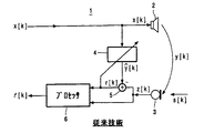
図1は、音響(アコースティック)エコーキャンセラ(AEC)1として具体化される、最初に説明されるべき干渉キャンセラ1の全体像を示している。このようなAEC1は、例えば、スピーカーフォン装置、テレコンファレンス装置、又は移動電話、ハンズフリー電話等の電話装置のような、今日のほとんどの全2重通信システムにおいて、重要な構成要素である。スピーカ2及びマイクロフォン3が、AEC1に結合されるとともに一般に互いに非常に近くに取り付けられる、今日の電話機において、このようなAECは、邪魔なローカルエコーを除去する。同じことが、主として1つ又は複数のスピーカ及びマイクロフォンがAEC1に結合されるテレコンファレンス装置にも当てはまる。
FIG. 1 shows an overview of an
図1は、遠端から到来する信号x[k]を示し、この信号は、近端側で、スピーカ2によって再生される。添字kは、信号xがサンプリングされることを示す。近端スピーカから主に生じるスピーチs[k]のほかに、マイクロフォン3は、スピーカ2からマイクロフォン3までのエコー経路を通じて生成される反響した遠端エコーを含む信号y[k]も検知する。従って、近端のマイクロフォン信号z[k]については、(ノイズn[k]が無視される場合)z[k]=s[k]+y[k]となる。AEC1は、適応フィルタ4によって、エコー評価信号、

AEC1の動作は、その中に残余エコープロセッサ6を有することによって拡張されうる。この場合、信号r’[k]が、AEC1の出力信号である。実際には、適応フィルタ4は、その有限のデジタルフィルタ長、トラッキング問題及び非線形効果のため、スピーカ2とマイクロフォン3との間の音響経路の伝達関数を常に正確にモデル化することができるわけではない。ポストプロセッサであるプロセッサ6は、これが十分なエコー抑制及びロバストネスをいつでも提供するという重要な利点をもつ。r’[k]と示されるエコーポストプロセッサ6の出力信号は、遠端に結合される。ポストプロセッサ6の動作は、良く知られていると考えられるが、例えば欧州特許出願公開第0 843 934号明細書から理解することができ、その開示は、本明細書に参照によって盛り込まれるものとする。主に、AEC1は、任意の適応フィルタのタイプでありうる。エコーキャンセラの係数を調整するための適切なアルゴリズムの例は、最小二乗平均(LMS)若しくは正規化LMSアルゴリズム、又は再帰的最小二乗(RLS)アルゴリズムである。
The operation of AEC 1 can be extended by having a
遠端スピーカと近端スピーカとの間の通信セッションの開始時、適応フィルタ4及びそののちスペクトルプロセッサ6は、スピーカ2とマイクロフォン3との間の音響インパルス応答のモデルに収束し始める。遠端スピーカの信号タイプ、適応フィルタ4の長さ及びアルゴリズムで使用されるステップサイズに依存して、適応フィルタ4が収束するにはいくらかの時間がかかり、通常は数秒かかる。この間、エコー抑制は−それが仮にも存在する場合−不十分であり、結果として、パーティ間の通信の不快な開始をもたらすことになる。一般的な問題は、可能な限り迅速にマイクロフォン3から生じる信号に存在するエコーの正確なスペクトル評価を得ることである。こののちはじめて、残余エコーは、エコーサプレッサ8によって抑制されることができ、これに続き、ステップサイズを最適化するためにステップサイズの制御が行われる。これらの問題は、複雑でクリティカルなスピーチ検出器を利用する必要がある場合、解決するのが困難である。
At the start of the communication session between the far-end speaker and the near-end speaker, the adaptive filter 4 and then the
そこでエコーモデルミスマッチ補償器7が使用され、これは、図2のエコーキャンセラの全体的なスキームに含まれる。補償器7は、図3に詳細に示されている。図2は、上述した信号r[k]、z[k]、y^[k]の各々についてスペクトル解析及び変換を実施する個々の信号解析ブロックAを示す。変換は結果として、ρ及びφとそれぞれ概略的に示されている上述の信号の振幅及び位相表現を与える。合成ブロックSによる出力信号r’[k]の再構成のためには、プロセッサ入力信号r[k]の位相φ(R)だけが、変更されたパワースペクトルR’mod(k)と共に使用される。R’mod(k)の変更についてはのちに説明する。通信セッションの開始後しばらくたってから、すなわち定常状態にある場合、適応フィルタ4は、すでに収束しており、R’mod(k)は、変更されていない前のスペクトル値R’を表す。ここで、
![]()
![]()
![]()
![]()
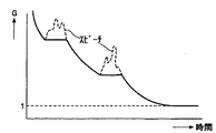
上式で、Zj及びY^jは、それぞれ、マイクロフォン信号z[k]及び適応フィルタ出力信号y^[k]の周波数ビンjのスペクトル振幅を表し、「min」は、連結かっこ間の絶対値の比の最小値が、ブロックサイズBを有するkブロックの全数のうち複数のL個の時間フレームをカバーするタイムスパンを通じてトラッキングされることを意味する。Y^[(k−i)B]j=0の場合、方程式(1)の絶対値比は、無限(infinite)にセットされる。方程式(1)の最小トラッキング処理を適用する効果は、ローカルの近端スピーチ(図4に点線で示される)の存在が、G[kB]jを増加させず、従ってエコーモデルスマッチ評価の不所望の上方へのバイアスをもたらさないことである。従って、通信セッションの開始時、スピーチは、エコーモデルの構築に不利な影響を及ぼさない。これは、|Y^mod|によって表されるミスマッチ信号を生成する方程式(1)が使用され、このミスマッチ信号が、スピーチに依存しない減衰を示すからである。 Where Z j and Y ^ j represent the spectral amplitude of the frequency bin j of the microphone signal z [k] and the adaptive filter output signal y ^ [k], respectively, and “min” is the absolute value between the connected parentheses. It means that the minimum value ratio is tracked through a time span covering a plurality of L time frames out of the total number of k blocks having a block size B. When Y ^ [(k−i) B] j = 0, the absolute value ratio of equation (1) is set to infinite. The effect of applying the minimum tracking process of equation (1) is that the presence of local near-end speech (indicated by the dotted line in FIG. 4) does not increase G [kB] j and is therefore undesirable for echo model match evaluation. Does not cause an upward bias. Thus, at the start of a communication session, speech does not adversely affect the construction of the echo model. This is because the equation (1) that generates the mismatch signal represented by | Y ^ mod | is used, and this mismatch signal exhibits speech-independent attenuation.
この振る舞いは、図4にグラフィックに示されている。図4は、時間の関数として、評価Gの図示される減衰を示す。ここで、Gの増加しない−平坦な−部分は、スピーチの期間を表し、これのエコー評価のモデルへの悪影響は、平らにされる(静められる)。これによって、歪められていないスピーチが得られる。 This behavior is illustrated graphically in FIG. FIG. 4 shows the illustrated decay of the evaluation G as a function of time. Here, the non-increasing -flat portion of G represents the duration of speech, and its negative impact on the model of echo estimation is flattened (sedated). This gives an undistorted speech.
Lフレームより長い期間、いかなる周波数ビンjにおいても刺激又はスピーチのない状況において、モデルミスマッチは、無限にセットされる。スペクトルポストプロセッサ6によるエコー抑制の量は、ゼロ刺激の場合にはゼロであるので、求められる信号の歪みはない。
In situations where there is no stimulus or speech in any frequency bin j for a period longer than L frames, the model mismatch is set to infinity. Since the amount of echo suppression by the
好適には、方程式(1)によってカバーされるタイムスパンは、スピーチの中の少なくとも1つのポーズを含む。実際には、タイムスパンは、少なくとも4乃至5秒続く。エコーモデルミスマッチ補償器7は、良く知られたシフトレジスタを有することができ、シフトレジスタは、比の分子及び分母の連続して計算される値を記憶することができる。
Preferably, the time span covered by equation (1) includes at least one pose in the speech. In practice, the time span lasts at least 4-5 seconds. The echo
図2は更に、エコーキャンセラ1が、特にエコーモデルミスマッチ補償器7に結合されるステップサイズ評価器8を有することを示す。これは、通信セッションの開始中にも、アルゴリズムで使用されるステップサイズが、通信の早い段階で最適化されることができるという更なる効果をもつ。この早めの最適化は、適用されるステップサイズ制御又はステップサイズ評価器8が動作する方法に、依存しない。評価器8があらゆる周波数ビンについてY^を使用することに関する限り、この量は、通信セッションの開始中、有利な結果を示すために、上述の関連するY^modと単に置き換えられることができる。更なる詳細に立ち入らずに、ステップサイズは、開始中及びその後の定常状態の間の両方の時間に、フルバンド最適ステップサイズをもたらすために、Y^modに関して最適化されることができる。更に、ステップサイズ制御は、周波数依存のやり方で実現されることができる。
FIG. 2 further shows that the
上述したエコーモデルミスマッチ評価と同じく、ノイズキャンセレーションの条件が、エコーモデルミスマッチ評価と組み合わされて又は組み合わされずに、関連するノイズモデルミスマッチ評価を導入するために同様に提案されることができる。図5及び図6は、ノイズキャンセラ1として具体化される、ここで説明されるべき干渉キャンセラ1の個々の実施例を示す。図1も参照して、スピーカ2が基準信号マイクロフォン9と置き換えられることを除いて、全体像は、図5及び図6の構成と非常に似ていることが分かる。マイクロフォン9は、基準信号、ここではノイズ信号を検知し、このノイズ信号及びスピーチが、マイクロフォン3によって検出される。適応フィルタ4は、マイクロフォン9及び3の間でノイズ経路をモデル化する。ここで信号z[k]は、スピーチs[k]及びノイズn[k]を含む。適応フィルタ4によってモデル化されるノイズ評価、
図6は、ノイズキャンセラの形の干渉キャンセラ1の実施例を示す。図6において、図1のスピーカは、基準マイクロフォン9と置き換えられている。基準マイクロフォン9は、ノイズn[k]のほかに、スピーチs[k]の一部も検出する。図5と同様に、マイクロフォン3は、スピーチ及びノイズを検知する。スピーチ及びノイズを含む信号z’[k]及びノイズ信号n’[k]に含まれるノイズを分離するために、ビーム形成器10が、ノイズキャンセラ1に含まれる。ビーム形成器の動作は、国際公開第99/27522号パンフレットから知られており、その開示は、参照によって本明細書に盛り込まれる。ノイズ評価、
干渉キャンセラ1の干渉モデルミスマッチ評価により、適応フィルタ4がより早く収束の状態になる場合、エコー及び/又はノイズパワースペクトルは、非常に正確に評価されることができ、これによって、音響キャンセラ1の有意な改善をもたらす。特に初期の収束フェーズにおいて、音響キャンセラの高品質の動作は、それがユーザの第一印象を決定するので、重要である。
If the interference model mismatch evaluation of the
上述の説明は、本質的に好適な実施例及び最良の実施の形態に関して記述されており、特許請求の範囲内にあるさまざまな変更、特徴及び特徴の組み合わせが、当業者の想到する範囲内にあるので、上述の実施例は、当該のシステム及び方法の例を制限するものとして決して解釈されてはならないことが分かるであろう。 The foregoing description has been made with reference to a preferred embodiment and best mode, and various modifications, features and combinations of features within the scope of the claims are within the scope of those skilled in the art. As such, it will be appreciated that the above-described embodiments should in no way be construed as limiting the examples of such systems and methods.
Claims (11)
近端スピーチ及び前記実際の干渉と共に、前記モデル化された干渉を処理するスペクトルプロセッサと、
を有する干渉キャンセラであって、
前記適応フィルタに結合され、ミスマッチ信号を前記スペクトルプロセッサに供給する干渉モデルミスマッチ補償器を更に有し、前記ミスマッチ信号が、スピーチに依存しない減衰を示すことを特徴とする干渉キャンセラ。 An adaptive filter that models interference;
A spectrum processor for processing the modeled interference along with near-end speech and the actual interference;
An interference canceller having
An interference canceller coupled to the adaptive filter, further comprising an interference model mismatch compensator for supplying a mismatch signal to the spectrum processor, wherein the mismatch signal exhibits speech independent attenuation.
前記干渉キャンセラが更に、前記適応フィルタに結合され、ミスマッチ信号を前記スペクトルプロセッサに供給する干渉モデルミスマッチ補償器を有し、前記ミスマッチ信号が、スピーチに依存しない減衰を示すことを特徴とする、システム。 A system comprising an interference canceller according to any one of claims 1 to 8, in particular a communication system such as a hands-free communication device such as a mobile phone, a speech recognition system or a voice control system, An interference canceller comprising: an adaptive filter that models actual interference; and a spectrum processor that processes the modeled interference along with near-end speech and the actual interference,
The interference canceller is further coupled to the adaptive filter and includes an interference model mismatch compensator for supplying a mismatch signal to the spectrum processor, wherein the mismatch signal exhibits speech-independent attenuation. .
干渉モデルミスマッチ信号が、前記実際の干渉をモデル化するために使用され、前記ミスマッチ信号が、スピーチに依存しない減衰を示すことを特徴とする、方法。 A method for canceling interference, in which actual interference is modeled, and the modeled interference, near-end speech and the actual interference are processed.
A method, characterized in that an interference model mismatch signal is used to model the actual interference and the mismatch signal exhibits speech independent attenuation.
前記干渉キャンセラが更に、前記適応フィルタに結合され、ミスマッチ信号を前記スペクトルプロセッサに供給する、干渉モデルミスマッチ補償器を有し、前記ミスマッチ信号が、スピーチに依存しない減衰を示すことを特徴とする信号。 9. A signal suitable for use in an interference canceller according to any one of claims 1 to 8, wherein the interference canceller models an adaptive filter that models actual interference, and the modeled signal. A spectrum processor for processing interference, near-end speech and said actual interference,
The interference canceller further comprises an interference model mismatch compensator coupled to the adaptive filter and supplying a mismatch signal to the spectrum processor, wherein the mismatch signal exhibits attenuation independent of speech .
Applications Claiming Priority (2)
| Application Number | Priority Date | Filing Date | Title |
|---|---|---|---|
| EP02077868 | 2002-07-16 | ||
| PCT/IB2003/002863 WO2004008731A1 (en) | 2002-07-16 | 2003-06-23 | Echo canceller with model mismatch compensation |
Publications (2)
| Publication Number | Publication Date |
|---|---|
| JP2005533427A true JP2005533427A (en) | 2005-11-04 |
| JP2005533427A5 JP2005533427A5 (en) | 2006-08-10 |
Family
ID=30011203
Family Applications (1)
| Application Number | Title | Priority Date | Filing Date |
|---|---|---|---|
| JP2004520975A Pending JP2005533427A (en) | 2002-07-16 | 2003-06-23 | Echo canceller with model mismatch compensation |
Country Status (7)
| Country | Link |
|---|---|
| US (1) | US20050175129A1 (en) |
| EP (1) | EP1523846A1 (en) |
| JP (1) | JP2005533427A (en) |
| KR (1) | KR20050021472A (en) |
| CN (1) | CN1669294A (en) |
| AU (1) | AU2003244935A1 (en) |
| WO (1) | WO2004008731A1 (en) |
Families Citing this family (11)
| Publication number | Priority date | Publication date | Assignee | Title |
|---|---|---|---|---|
| EP1803288B1 (en) * | 2004-10-13 | 2010-04-14 | Koninklijke Philips Electronics N.V. | Echo cancellation |
| EP2078301A1 (en) * | 2006-09-28 | 2009-07-15 | France Telecom | Noise and distortion reduction in a forward-type structure |
| GB2479776B (en) | 2010-04-22 | 2012-08-29 | Eads Uk Ltd | Testing joints between composite and metal parts |
| WO2016039765A1 (en) * | 2014-09-12 | 2016-03-17 | Nuance Communications, Inc. | Residual interference suppression |
| US10347273B2 (en) * | 2014-12-10 | 2019-07-09 | Nec Corporation | Speech processing apparatus, speech processing method, and recording medium |
| CN107872235B (en) * | 2017-02-24 | 2019-08-20 | 珠海市杰理科技股份有限公司 | The method and apparatus for reducing signal interference in wireless lan communication lsi |
| US10542153B2 (en) * | 2017-08-03 | 2020-01-21 | Bose Corporation | Multi-channel residual echo suppression |
| US10594869B2 (en) * | 2017-08-03 | 2020-03-17 | Bose Corporation | Mitigating impact of double talk for residual echo suppressors |
| EP3692704B1 (en) | 2017-10-03 | 2023-09-06 | Bose Corporation | Spatial double-talk detector |
| CN108488036B (en) * | 2018-05-04 | 2019-10-25 | 曲阜师范大学 | Wind-powered electricity generation magnetic suspension yaw system suspension control method based on model mismatch compensator |
| US10964305B2 (en) | 2019-05-20 | 2021-03-30 | Bose Corporation | Mitigating impact of double talk for residual echo suppressors |
Family Cites Families (8)
| Publication number | Priority date | Publication date | Assignee | Title |
|---|---|---|---|---|
| JP2947093B2 (en) * | 1994-11-02 | 1999-09-13 | 日本電気株式会社 | Method and apparatus for system identification with adaptive filters |
| WO1997045995A1 (en) * | 1996-05-31 | 1997-12-04 | Philips Electronics N.V. | Arrangement for suppressing an interfering component of an input signal |
| US6185300B1 (en) * | 1996-12-31 | 2001-02-06 | Ericsson Inc. | Echo canceler for use in communications system |
| US6510224B1 (en) * | 1999-05-20 | 2003-01-21 | Telefonaktiebolaget L M Ericsson | Enhancement of near-end voice signals in an echo suppression system |
| US7062039B1 (en) * | 1999-05-27 | 2006-06-13 | Telefonaktiebolaget Lm Ericsson | Methods and apparatus for improving adaptive filter performance by inclusion of inaudible information |
| US6522746B1 (en) * | 1999-11-03 | 2003-02-18 | Tellabs Operations, Inc. | Synchronization of voice boundaries and their use by echo cancellers in a voice processing system |
| US7054419B2 (en) * | 2001-01-02 | 2006-05-30 | Soundbite Communications, Inc. | Answering machine detection for voice message delivery method and system |
| US6950842B2 (en) * | 2002-01-23 | 2005-09-27 | Analog Devices, Inc. | Echo canceller having an adaptive filter with a dynamically adjustable step size |
-
2003
- 2003-06-23 WO PCT/IB2003/002863 patent/WO2004008731A1/en not_active Application Discontinuation
- 2003-06-23 US US10/520,870 patent/US20050175129A1/en not_active Abandoned
- 2003-06-23 KR KR10-2005-7000659A patent/KR20050021472A/en not_active Application Discontinuation
- 2003-06-23 EP EP03738409A patent/EP1523846A1/en not_active Withdrawn
- 2003-06-23 CN CNA038167573A patent/CN1669294A/en active Pending
- 2003-06-23 AU AU2003244935A patent/AU2003244935A1/en not_active Abandoned
- 2003-06-23 JP JP2004520975A patent/JP2005533427A/en active Pending
Also Published As
| Publication number | Publication date |
|---|---|
| KR20050021472A (en) | 2005-03-07 |
| US20050175129A1 (en) | 2005-08-11 |
| EP1523846A1 (en) | 2005-04-20 |
| CN1669294A (en) | 2005-09-14 |
| WO2004008731A1 (en) | 2004-01-22 |
| AU2003244935A1 (en) | 2004-02-02 |
Similar Documents
| Publication | Publication Date | Title |
|---|---|---|
| KR101469739B1 (en) | A device for and a method of processing audio signals | |
| JP5049277B2 (en) | Method and system for clear signal acquisition | |
| KR101250124B1 (en) | Apparatus and Method for Computing Control Information for an Echo Suppression Filter and Apparatus and Method for Computing a Delay Value | |
| JP4702371B2 (en) | Echo suppression method and apparatus | |
| KR101185820B1 (en) | Echo cancellation | |
| JP4913155B2 (en) | Acoustic echo canceller | |
| US7477735B2 (en) | System and method for enhanced stereo audio | |
| JP6243536B2 (en) | Echo cancellation | |
| JP5061853B2 (en) | Echo canceller and echo cancel program | |
| US20070058799A1 (en) | Communication apparatus capable of echo cancellation | |
| US20060188089A1 (en) | Reduction in acoustic coupling in communication systems and appliances using multiple microphones | |
| JP2002501338A (en) | Method and apparatus for improved echo suppression in a communication system | |
| JPWO2007049644A1 (en) | Echo suppression method and apparatus | |
| JP2008141734A (en) | Echo canceller and communication audio processing apparatus | |
| JP2004537219A (en) | Echo canceller with nonlinear echo suppressor for harmonic calculation | |
| JP2009246628A (en) | Acoustic echo canceler | |
| US10789933B1 (en) | Frequency domain coefficient-based dynamic adaptation control of adaptive filter | |
| JP2005533427A (en) | Echo canceller with model mismatch compensation | |
| Stenger et al. | An acoustic echo canceller with compensation of nonlinearities | |
| JP2003188776A (en) | Acoustic echo erasing method and device, and acoustic echo erasure program | |
| US6850783B1 (en) | Methods and apparatus for mitigating the effects of microphone overload in echo cancelation systems | |
| JP4396449B2 (en) | Reverberation removal method and apparatus | |
| US20050249347A1 (en) | Non stationary echo canceller | |
| CN115398934A (en) | Method, device, earphone and computer program for actively suppressing occlusion effect when reproducing audio signals | |
| JPH09116469A (en) | Echo noise cancellor and echo noise canceling method |
Legal Events
| Date | Code | Title | Description |
|---|---|---|---|
| A521 | Request for written amendment filed |
Free format text: JAPANESE INTERMEDIATE CODE: A523 Effective date: 20060622 |
|
| A621 | Written request for application examination |
Free format text: JAPANESE INTERMEDIATE CODE: A621 Effective date: 20060622 |
|
| A977 | Report on retrieval |
Free format text: JAPANESE INTERMEDIATE CODE: A971007 Effective date: 20090319 |
|
| A131 | Notification of reasons for refusal |
Free format text: JAPANESE INTERMEDIATE CODE: A131 Effective date: 20090924 |
|
| A02 | Decision of refusal |
Free format text: JAPANESE INTERMEDIATE CODE: A02 Effective date: 20100309 |