JP2005529341A - Method for SEM inspection of fluid containing sample - Google Patents
Method for SEM inspection of fluid containing sample Download PDFInfo
- Publication number
- JP2005529341A JP2005529341A JP2004511867A JP2004511867A JP2005529341A JP 2005529341 A JP2005529341 A JP 2005529341A JP 2004511867 A JP2004511867 A JP 2004511867A JP 2004511867 A JP2004511867 A JP 2004511867A JP 2005529341 A JP2005529341 A JP 2005529341A
- Authority
- JP
- Japan
- Prior art keywords
- sample
- visualizing
- scanning
- environment according
- moist environment
- Prior art date
- Legal status (The legal status is an assumption and is not a legal conclusion. Google has not performed a legal analysis and makes no representation as to the accuracy of the status listed.)
- Pending
Links
Images


Classifications
-
- B—PERFORMING OPERATIONS; TRANSPORTING
- B01—PHYSICAL OR CHEMICAL PROCESSES OR APPARATUS IN GENERAL
- B01L—CHEMICAL OR PHYSICAL LABORATORY APPARATUS FOR GENERAL USE
- B01L3/00—Containers or dishes for laboratory use, e.g. laboratory glassware; Droppers
- B01L3/50—Containers for the purpose of retaining a material to be analysed, e.g. test tubes
- B01L3/508—Containers for the purpose of retaining a material to be analysed, e.g. test tubes rigid containers not provided for above
- B01L3/5085—Containers for the purpose of retaining a material to be analysed, e.g. test tubes rigid containers not provided for above for multiple samples, e.g. microtitration plates
- B01L3/50855—Containers for the purpose of retaining a material to be analysed, e.g. test tubes rigid containers not provided for above for multiple samples, e.g. microtitration plates using modular assemblies of strips or of individual wells
-
- B—PERFORMING OPERATIONS; TRANSPORTING
- B01—PHYSICAL OR CHEMICAL PROCESSES OR APPARATUS IN GENERAL
- B01L—CHEMICAL OR PHYSICAL LABORATORY APPARATUS FOR GENERAL USE
- B01L3/00—Containers or dishes for laboratory use, e.g. laboratory glassware; Droppers
- B01L3/50—Containers for the purpose of retaining a material to be analysed, e.g. test tubes
- B01L3/508—Containers for the purpose of retaining a material to be analysed, e.g. test tubes rigid containers not provided for above
-
- H—ELECTRICITY
- H01—ELECTRIC ELEMENTS
- H01J—ELECTRIC DISCHARGE TUBES OR DISCHARGE LAMPS
- H01J37/00—Discharge tubes with provision for introducing objects or material to be exposed to the discharge, e.g. for the purpose of examination or processing thereof
- H01J37/02—Details
- H01J37/20—Means for supporting or positioning the objects or the material; Means for adjusting diaphragms or lenses associated with the support
-
- H—ELECTRICITY
- H01—ELECTRIC ELEMENTS
- H01J—ELECTRIC DISCHARGE TUBES OR DISCHARGE LAMPS
- H01J37/00—Discharge tubes with provision for introducing objects or material to be exposed to the discharge, e.g. for the purpose of examination or processing thereof
- H01J37/02—Details
- H01J37/244—Detectors; Associated components or circuits therefor
-
- B—PERFORMING OPERATIONS; TRANSPORTING
- B01—PHYSICAL OR CHEMICAL PROCESSES OR APPARATUS IN GENERAL
- B01L—CHEMICAL OR PHYSICAL LABORATORY APPARATUS FOR GENERAL USE
- B01L2200/00—Solutions for specific problems relating to chemical or physical laboratory apparatus
- B01L2200/06—Fluid handling related problems
- B01L2200/0689—Sealing
-
- B—PERFORMING OPERATIONS; TRANSPORTING
- B01—PHYSICAL OR CHEMICAL PROCESSES OR APPARATUS IN GENERAL
- B01L—CHEMICAL OR PHYSICAL LABORATORY APPARATUS FOR GENERAL USE
- B01L2300/00—Additional constructional details
- B01L2300/04—Closures and closing means
- B01L2300/041—Connecting closures to device or container
- B01L2300/042—Caps; Plugs
-
- B—PERFORMING OPERATIONS; TRANSPORTING
- B01—PHYSICAL OR CHEMICAL PROCESSES OR APPARATUS IN GENERAL
- B01L—CHEMICAL OR PHYSICAL LABORATORY APPARATUS FOR GENERAL USE
- B01L2300/00—Additional constructional details
- B01L2300/06—Auxiliary integrated devices, integrated components
- B01L2300/0627—Sensor or part of a sensor is integrated
- B01L2300/0654—Lenses; Optical fibres
-
- B—PERFORMING OPERATIONS; TRANSPORTING
- B01—PHYSICAL OR CHEMICAL PROCESSES OR APPARATUS IN GENERAL
- B01L—CHEMICAL OR PHYSICAL LABORATORY APPARATUS FOR GENERAL USE
- B01L2300/00—Additional constructional details
- B01L2300/08—Geometry, shape and general structure
- B01L2300/0809—Geometry, shape and general structure rectangular shaped
- B01L2300/0829—Multi-well plates; Microtitration plates
-
- G—PHYSICS
- G01—MEASURING; TESTING
- G01N—INVESTIGATING OR ANALYSING MATERIALS BY DETERMINING THEIR CHEMICAL OR PHYSICAL PROPERTIES
- G01N1/00—Sampling; Preparing specimens for investigation
- G01N1/28—Preparing specimens for investigation including physical details of (bio-)chemical methods covered elsewhere, e.g. G01N33/50, C12Q
- G01N1/36—Embedding or analogous mounting of samples
-
- H—ELECTRICITY
- H01—ELECTRIC ELEMENTS
- H01J—ELECTRIC DISCHARGE TUBES OR DISCHARGE LAMPS
- H01J2237/00—Discharge tubes exposing object to beam, e.g. for analysis treatment, etching, imaging
- H01J2237/20—Positioning, supporting, modifying or maintaining the physical state of objects being observed or treated
- H01J2237/2002—Controlling environment of sample
- H01J2237/2003—Environmental cells
-
- H—ELECTRICITY
- H01—ELECTRIC ELEMENTS
- H01J—ELECTRIC DISCHARGE TUBES OR DISCHARGE LAMPS
- H01J2237/00—Discharge tubes exposing object to beam, e.g. for analysis treatment, etching, imaging
- H01J2237/20—Positioning, supporting, modifying or maintaining the physical state of objects being observed or treated
- H01J2237/2005—Seal mechanisms
- H01J2237/2006—Vacuum seals
-
- H—ELECTRICITY
- H01—ELECTRIC ELEMENTS
- H01J—ELECTRIC DISCHARGE TUBES OR DISCHARGE LAMPS
- H01J2237/00—Discharge tubes exposing object to beam, e.g. for analysis treatment, etching, imaging
- H01J2237/20—Positioning, supporting, modifying or maintaining the physical state of objects being observed or treated
- H01J2237/201—Positioning, supporting, modifying or maintaining the physical state of objects being observed or treated for mounting multiple objects
-
- H—ELECTRICITY
- H01—ELECTRIC ELEMENTS
- H01J—ELECTRIC DISCHARGE TUBES OR DISCHARGE LAMPS
- H01J2237/00—Discharge tubes exposing object to beam, e.g. for analysis treatment, etching, imaging
- H01J2237/26—Electron or ion microscopes
- H01J2237/2602—Details
- H01J2237/2605—Details operating at elevated pressures, e.g. atmosphere
- H01J2237/2608—Details operating at elevated pressures, e.g. atmosphere with environmental specimen chamber
Landscapes
- Chemical & Material Sciences (AREA)
- Analytical Chemistry (AREA)
- Health & Medical Sciences (AREA)
- General Health & Medical Sciences (AREA)
- Hematology (AREA)
- Clinical Laboratory Science (AREA)
- Chemical Kinetics & Catalysis (AREA)
- Analysing Materials By The Use Of Radiation (AREA)
- Sampling And Sample Adjustment (AREA)
- Investigating Or Analysing Biological Materials (AREA)
Abstract
【解決手段】 湿った環境でサンプルを視覚化する方法は、サンプルを湿った環境の標本エンクロージャ内に導入し、走査型電子顕微鏡において該標本エンクロージャ内の該サンプルを走査し、これにより、該サンプルを視覚化する、各工程を備える。A method of visualizing a sample in a wet environment introduces the sample into a specimen enclosure in a wet environment and scans the sample in the specimen enclosure in a scanning electron microscope, whereby the sample Each step is visualized.
Description
出願人は、「自動化SEMを使用した、無傷の細胞の分子の定量パターン分析」という標題で、2002年7月8日に出願された、米国仮特許出願シリアル番号60/393,747号、「走査型電子顕微鏡(SEM)の検査システムのための標本エンクロージャ」という標題で、2003年2月20日に出願された、米国仮特許出願シリアル番号60/448,808号、「走査型電子顕微鏡と蛍光性又はシンチレーションとを持つマーカーとを使用した、生体サンプルの蛍光画像形成のための装置」という標題で、2002年6月5日に出願された、イスラエル特許出願シリアル番号150054号、並びに、「湿った環境におけるサンプルの走査型電子顕微鏡による画像形成のための自動化適合性の装置」という標題で、2002年6月5日に出願された、イスラエル特許出願シリアル番号150055号の優先権を主張する。 Applicants have filed US Provisional Patent Application Serial No. 60 / 393,747, filed July 8, 2002, entitled “Quantitative Pattern Analysis of Intact Cell Molecules Using Automated SEM”, “ US Provisional Patent Application Serial No. 60 / 448,808, filed February 20, 2003, entitled “Specimen Enclosure for Scanning Electron Microscope (SEM) Inspection System” Israel Patent Application Serial No. 150054, filed June 5, 2002, entitled “Apparatus for Fluorescence Imaging of Biological Samples Using Fluorescent or Scintillation Markers”, and “ "Automated compatible device for imaging of samples in a damp environment by scanning electron microscopy" Filed 5 days, claims priority of Israel patent application Serial No. 150,055.
本発明は、概して、サンプルを含む流体のSEM検査のための方法に係り、より詳しくは、湿った環境においてサンプルを視覚化させる方法に関する。 The present invention relates generally to a method for SEM inspection of fluid containing a sample, and more particularly to a method for visualizing a sample in a humid environment.
以下の列挙された文献が、当該技術分野の現在の状態を表すと考えられ、ここで参照されたことにより各々の開示内容が本願に組み込まれる。
生体細胞及び組織の顕微鏡検査は、臨床診断並びに生命科学の研究の多様な分野において中枢をなすツールである。光学顕微鏡(LM)は、薄い(数ミクロン)サンプルで実行され、該サンプルには、細胞、無細胞材料、又は、組織の薄い層若しくは薄片が含まれており、これらは、例えば、化学薬品等のコントラスト剤又は抗体で染色することができる。透過型電子顕微鏡(TEM)は、通常、特殊に形成準備された超薄型の薄片(0.1ミクロン以下)を必要とし、細胞内情報の豊富さを明らかにする。前述した技術の各々は、制約を持っている。即ち、光学顕微鏡の解像度は、回折により約0.25ミクロンに制限され、TEMの使用は、サンプルの広範囲に亘る処理により妨げられ、サンプルの構造をかなり変えてしまうおそれがある。標準的なTEMのためのサンプルの準備は、特殊な技術を必要とし、達成するまでに少なくとも数日はかかる。非常に薄い切片は、サンプルの非常に制限された、しばしば任意的となる部分を与え、多重連続薄片の画像形成を必要としている。
The following listed documents are believed to represent the current state of the art, and each disclosure is incorporated herein by reference.
Biological cell and tissue microscopy is a central tool in various fields of clinical diagnosis and life science research. Light microscopy (LM) is performed on thin (several microns) samples that contain cells, acellular material, or thin layers or slices of tissue, such as chemicals Can be stained with a contrast agent or an antibody. Transmission electron microscopy (TEM) usually requires specially prepared ultra-thin slices (less than 0.1 microns) to reveal the abundance of intracellular information. Each of the techniques described above has its limitations. That is, the resolution of the optical microscope is limited to about 0.25 microns due to diffraction, and the use of TEM can be hampered by extensive processing of the sample and can significantly alter the structure of the sample. Sample preparation for a standard TEM requires special techniques and takes at least a few days to achieve. Very thin sections give very limited, often optional parts of the sample and require the imaging of multiple consecutive slices.
高い解像度の画像は、走査型電子顕微鏡(SEM)によって達成することもできる。走査型電子顕微鏡では、合焦された電子ビームがサンプルを連続的に走査し、続いて連続的に生じる信号が画像を発生するため使用される。非常にしばしば、2次電子が検出され、サンプルの表面トポグラフィーに関する情報を与える。後方散乱電子の検出は、表面より下方の短距離、典型的には数ミクロンまでの距離にあるサンプルの領域の材料分布に関する情報を与える。SEMは、電子が、画像を生じさせるためサンプルを横断する必要がないという意味で、画像形成処理の反射モードである。このため、サンプルは、任意の厚さを持っていてもよく、薄片にする必要はない。しかし、サンプルは、走査電子ビームの妨げられない運動を可能にするため真空環境に置かなければならない。従って、サンプルは、広範囲に亘って、脱水され、乾燥されなければならない。更には、乾燥されたとき、生体及び他の有機サンプルは、電気的に絶縁されるようになり、電子ビームによるサンプルの帯電に起因して人為構造をもたらす。それによって、サンプルは、通常、カーボン又は金属の導電層で被覆されている。 High resolution images can also be achieved with a scanning electron microscope (SEM). In a scanning electron microscope, a focused electron beam continuously scans the sample, and the subsequently generated signal is used to generate an image. Very often secondary electrons are detected, giving information about the surface topography of the sample. The detection of backscattered electrons gives information about the material distribution in the region of the sample at a short distance below the surface, typically up to a few microns. SEM is a reflective mode of the imaging process in the sense that electrons do not have to traverse the sample to produce an image. For this reason, the sample may have any thickness and need not be sliced. However, the sample must be placed in a vacuum environment to allow unimpeded movement of the scanning electron beam. Therefore, the sample must be dehydrated and dried over a wide area. Furthermore, when dried, living organisms and other organic samples become electrically isolated, resulting in artifacts due to the charging of the sample by the electron beam. Thereby, the sample is usually coated with a conductive layer of carbon or metal.
広範囲に亘る乾燥無しに、生体又は他の湿ったサンプルを観察する一つのアプローチが環境SEM及び類似の技術の開発であってきた。これらの方法は、差動ポンプ及び多重アパーチャに基づいており、走査電子ビームの経路のほとんどを通して高真空を維持しつつ、サンプルの近傍領域で水蒸気圧力に近い局所化された圧力を可能にする。これらの方法では、サンプルは、部分的真空にさらされており、脱水状態を維持するために、低温、及び、複雑化した手動による正圧の維持の両方が要求される。実際に、この技術を使用した生体研究の公開された報告のうち少数が、高い水準で首尾一貫した結果を得る困難さを証明している。 One approach to observe living organisms or other wet samples without extensive drying has been the development of environmental SEM and similar technologies. These methods are based on differential pumps and multiple apertures, allowing localized pressures close to the water vapor pressure in the region near the sample while maintaining a high vacuum throughout most of the scanning electron beam path. In these methods, the sample is subjected to a partial vacuum, requiring both low temperature and complex manual positive pressure maintenance to maintain dehydration. In fact, a few of the published reports of biological studies using this technique have proved difficult to obtain consistent results at a high level.
高解像度の画像形成は、生物学上幅広い用途を持っている。これらの用途には、細胞、組織、微生物、及び、ウィルス、並びに、例えば生物学的な環境上若しくは工業上の流体、乳濁液及び懸濁液等の無細胞サンプルの画像形成が含まれている。 High-resolution imaging has a wide range of biological applications. These applications include imaging of cells, tissues, microorganisms and viruses and cell-free samples such as biological environment or industrial fluids, emulsions and suspensions. Yes.
最近のレビューは、臨床診断における電子顕微鏡の使用を論じている(タッカー、J.A.2000)。少ないが有意な比率のケース(3〜8%)において、適切な診断が、電子顕微鏡に基づいてのみなすことができることが見出されている。このことは、特に、腫瘍学、及び、腎臓疾患等の選択された領域で断言することができる(タッカー2000)。これらの数は、おそらくは過小評価である。電子顕微鏡の使用は、主要には、ユーティリティの欠如によっては制限されないが、コスト、結果を生成するのに必要となる時間、及び、低いスループットを考慮することによって制限されるからである。かくして、光学顕微鏡と互換性のあるサンプル準備手続きで電子顕微鏡の高い解像度を達成する、生体組織及び細胞のための画像形成システムに対する、かなりの必要性が存在している。 A recent review discusses the use of electron microscopy in clinical diagnosis (Tucker, JA 2000). It has been found that in a small but significant proportion of cases (3-8%), a proper diagnosis can only be made on the basis of an electron microscope. This can be stated especially in selected areas such as oncology and kidney disease (Tucker 2000). These numbers are probably underestimated. The use of an electron microscope is primarily not limited by the lack of utilities, but is limited by considering cost, time required to produce results, and low throughput. Thus, there is a significant need for an imaging system for living tissue and cells that achieves the high resolution of an electron microscope with a sample preparation procedure compatible with an optical microscope.
「走査型電子顕微鏡を使用した、非真空環境に置かれたサンプルの検査のための装置及び方法」と題された、本願発明者の一人による、現在係属中のPCT/IL01/01108は、大気圧近傍圧力で、幅広い温度範囲に亘って、湿った環境中の湿ったサンプルの画像形成を可能にする、非真空式走査型電子顕微鏡(SEM)装置を開示している。これは、広範なサンプル準備手続きのための必要性を無くし、かくして、例えば高い解像度及び高いコントラスト又は信号対ノイズ比等といった電子顕微鏡の利点と、例えばサンプル準備手続きの容易さ及び迅速さといった光学顕微鏡の利点とを結合させる。このことは、電子に対しては透過性であるが流体に対しては不透過性であると共に、典型的には大気圧である容器の内部とSEMの画像形成領域における真空との間の圧力差に耐えるのに十分に強い、薄い仕切り膜により覆われたサンプル容器の使用により達成される。この種の膜は、以下では、仕切り膜、又は、電子透過性で流体不浸透性の膜と称される。 PCT / IL01 / 01108, currently pending by one of the inventors, entitled “Apparatus and Method for Examination of Samples Placed in a Non-Vacuum Environment Using a Scanning Electron Microscope” A non-vacuum scanning electron microscope (SEM) apparatus is disclosed that enables the imaging of moist samples in a moist environment over a wide temperature range at near atmospheric pressure. This eliminates the need for extensive sample preparation procedures and thus the advantages of electron microscopes such as high resolution and high contrast or signal-to-noise ratio and optical microscopes such as the ease and speed of sample preparation procedures. Combine with the benefits of. This is the pressure between the interior of the container, which is permeable to electrons but impermeable to fluids, and typically at atmospheric pressure, and the vacuum in the imaging area of the SEM. This is achieved by the use of a sample container covered by a thin partition membrane that is strong enough to withstand the difference. This type of membrane is hereinafter referred to as a partition membrane or an electron permeable and fluid impermeable membrane.
非真空式SEMの前述した特徴は、次の態様で、流体含有サンプル、特に生物学的サンプルの観察に適用される。 The aforementioned features of the non-vacuum SEM apply in the following manner to the observation of fluid containing samples, in particular biological samples.
1. 真空からのサンプルの分離は、湿ったサンプルの直接的な視覚化を可能にする。これは、水置換及び臨界点乾燥を含む、全ての脱水処置に対する必要性を直ちに無くす。湿った状態は、サンプルの自然な状態にほとんど似ており、脱水の間に歪められ又は破壊されるおそれのある特徴を保存する。この利点は、真の構成が細胞及び細胞外基質の両方を含む、組織の観察において特に重要となる。更には、サンプル内及びサンプルの回りの流体の存在は、効率的な電荷及び余剰熱の消失を可能にする。これは、サンプル帯電に起因した人為構造、並びに熱損傷を無くす。 1. Separation of the sample from the vacuum allows direct visualization of the wet sample. This immediately eliminates the need for all dehydration procedures, including water displacement and critical point drying. The wet state is almost similar to the natural state of the sample and preserves features that can be distorted or destroyed during dehydration. This advantage is particularly important in tissue observation where the true configuration includes both cells and extracellular matrix. Furthermore, the presence of fluid in and around the sample allows efficient charge and excess heat dissipation. This eliminates artifacts and thermal damage due to sample charging.
2. 生物学的組織の電子顕微鏡検査は、非常にしばしば、2つの画像形成モードでなされる。透過型電子顕微鏡検査(TEM)は、サンプルを透過した電子を利用する。即ち、サンプルの全厚さは、画像に寄与する。透過技術は、サンプルの厚さに関して厳しい制約を課す。典型的には、要求される厚さは50nmであり、これは、超高電圧顕微鏡では3μmまで増大させることができる。走査型電子顕微鏡検査は、反射モードを使用し、最も頻繁にはサンプルの表面形状のみを画像形成する2次電子を検出する。非真空式SEM技術は、走査型電子顕微鏡で後方散乱電子の検出を使用する。電子ビームは、サンプル内を貫通し、後方散乱された電子は、サンプル表面を越えて数ミクロンの深さまでのサンプル特徴を明らかにする。かくして、画像形成の電子散乱/反射モードが陥られるが、画像は、表面には限定されず、サンプルの内部構造が明らかにされる。更には、検出が反射モードでなされるので、相互作用する体積部分を越えて存在する任意材料は、画像形成には効果を及ぼさない。従って、サンプルは、画像形成される領域を遙かに超える厚さを持つことができる。典型的には、数ミリメートル厚の組織断片を見ることができる。表面に最も近接している数マイクロメートル以下の材料層のみが、サンプルのバルク部からの干渉無しに、走査画像に寄与する。画像形成された領域の厚さは、電子ビームの加速電圧を変化させることにより、変調することができる。非真空式SEMは、かくして、サンプルの実際の薄片化の必要無しに、「仮想的薄片」を与える。これは、サンプルを埋め込んだり、凍結させたりする必要性を無くす。そうでなければ、サンプルの薄片化を可能にすることが要求される。最終的には、電子後方散乱効率のサンプル材料組成(原子番号Zによる)の依存性は、TEM画像形成の特徴である重金属染色が無い場合でさえもコントラストを形成する。生体サンプル内部の脂質、リン、塩の濃度の局所的な差異に基づいて細胞小器官を識別することができる。幅広い範囲の染色及び標識工程を、コントラストを向上させるため使用することができる。 2. Very often, electron microscopy of biological tissue is done in two imaging modes. Transmission electron microscopy (TEM) utilizes electrons that have passed through a sample. That is, the total thickness of the sample contributes to the image. Transmission technology imposes severe constraints on sample thickness. Typically, the required thickness is 50 nm, which can be increased to 3 μm in an ultra high voltage microscope. Scanning electron microscopy uses a reflection mode and most often detects secondary electrons that image only the surface shape of the sample. Non-vacuum SEM technology uses detection of backscattered electrons in a scanning electron microscope. The electron beam penetrates through the sample, and the backscattered electrons reveal sample characteristics to a depth of a few microns across the sample surface. Thus, although the electron scattering / reflection mode of imaging is compromised, the image is not limited to the surface, revealing the internal structure of the sample. Furthermore, since the detection is done in reflection mode, any material that exists beyond the interacting volume has no effect on imaging. Thus, the sample can have a thickness that far exceeds the area to be imaged. Typically, a few millimeter thick tissue fragments can be seen. Only the few micrometer or less material layer closest to the surface contributes to the scanned image without interference from the bulk portion of the sample. The thickness of the imaged area can be modulated by changing the acceleration voltage of the electron beam. Non-vacuum SEM thus provides a “virtual flake” without the need for actual thinning of the sample. This eliminates the need to embed or freeze the sample. Otherwise, it is required to allow the sample to be thinned. Eventually, the dependence of the electron backscattering efficiency on the sample material composition (by atomic number Z) creates contrast even in the absence of heavy metal staining that is characteristic of TEM imaging. Organelles can be identified based on local differences in lipid, phosphorus, and salt concentrations within a biological sample. A wide range of staining and labeling steps can be used to improve contrast.
非真空式SEM技術の追加の能力は、電子ビームで走査する間にサンプルから放射された光を同時に検出する能力である。走査電子ビームは、サンプル内の分子を励起し、これにより当該分子は、特徴的な波長(陰極ルミネッセンス)で光を放射することができる。光強度は、輝く分子の分布の画像を導出するため使用される。該分子は、生物学的サンプルに外的要因無しに特有のものであるか、又は、外的に導入することができる標識のいずれかである。この画像は、電子物質相互作用により制限される解像度で、光の回折によってではない、後方散乱電子(BSE)による画像形成と同時に得られる。同様に、走査されたサンプルから放射されるX線を、従来の検出器及び方法を使用して検出することができ、材料組成及び完全に水和されたサンプルの分布に関する追加の情報を与える。詳しくは、X線分析を、例えばカルシウム、鉄、ナトリウム、カリウム、銅若しくは亜鉛等の金属、又はヨウ素、硫黄若しくは蛍光体等の他の元素を含む領域を探し当て、定量化するため使用することができる。 An additional capability of non-vacuum SEM technology is the ability to simultaneously detect light emitted from the sample while scanning with an electron beam. The scanning electron beam excites molecules in the sample so that the molecules can emit light at a characteristic wavelength (cathodoluminescence). The light intensity is used to derive an image of the glowing molecule distribution. The molecule is either unique to the biological sample without external factors, or is a label that can be introduced externally. This image is obtained simultaneously with image formation by backscattered electrons (BSE), with resolution limited by electronic matter interactions and not by light diffraction. Similarly, X-rays emitted from scanned samples can be detected using conventional detectors and methods, providing additional information regarding material composition and distribution of fully hydrated samples. Specifically, X-ray analysis can be used to locate and quantify regions containing other elements such as metals such as calcium, iron, sodium, potassium, copper or zinc, or iodine, sulfur or phosphors. it can.
本発明の別の目的は、湿ったサンプル、詳しくは生物学的サンプルの自動電子顕微鏡検査のための手段を提供することである。そのような自動化された電子顕微鏡検査は、半導体産業で幅広く応用されてきた。自動化電子顕微鏡検査の湿ったサンプルへの応用の主要な障壁は、例えば、乾燥、埋め込み、薄片化若しくは薄片化等のサンプル準備手続きを用いる必要性である。これらは、非常に複雑であり、自動化に従うことができない。本発明は、走査型電子顕微鏡において湿ったサンプルの直接画像形成のための手段を提供し、かくして、前述した準備手続きのための必要性を無くす。本発明は、このようにして、湿ったサンプルの自動化された電子顕微鏡検査のための手段を提供する。 Another object of the invention is to provide a means for automatic electron microscopy of wet samples, in particular biological samples. Such automated electron microscopy has been widely applied in the semiconductor industry. A major barrier to the application of automated electron microscopy to wet samples is the need to use sample preparation procedures such as drying, embedding, slicing or slicing. These are very complex and cannot follow automation. The present invention provides a means for direct imaging of wet samples in a scanning electron microscope, thus eliminating the need for the preparatory procedures described above. The present invention thus provides a means for automated electron microscopy of wet samples.
以上により、本発明の好ましい実施形態によれば、湿った環境でサンプルを視覚化する方法が提供され、該方法は、サンプルを湿った環境の標本エンクロージャ内に導入し、走査型電子顕微鏡において標本エンクロージャ内のサンプルを走査し、これにより、該サンプルを視覚化する、各工程を備える。 Thus, according to a preferred embodiment of the present invention, a method is provided for visualizing a sample in a moist environment, the method introducing the sample into a specimen enclosure in a moist environment, and the specimen in a scanning electron microscope. Each step includes scanning the sample in the enclosure, thereby visualizing the sample.
本発明の別の好ましい実施形態によれば、湿った環境でサンプルを視覚化する方法が更に提供され、該方法は、湿った環境の標本エンクロージャ内にサンプルを導入し、多数の異なる電子エネルギーレベルで、走査型電子顕微鏡の標本エンクロージャ内のサンプルを走査する、各工程を備える。 According to another preferred embodiment of the present invention, there is further provided a method for visualizing a sample in a moist environment, the method introducing the sample into a specimen enclosure in a moist environment, and a number of different electronic energy levels. Each step of scanning the sample in the specimen enclosure of the scanning electron microscope is provided.
本発明の更に別の好ましい実施形態によれば、湿った環境で多成分サンプルの少なくとも1つの成分を視覚化する方法が更に提供され、該方法は、湿った環境の標本エンクロージャ内に多成分サンプルを導入し、走査型電子顕微鏡の標本エンクロージャ内の多成分サンプルを走査し、これにより、該多成分サンプルの少なくとも1つの成分を視覚化する、各工程を備える。 According to yet another preferred embodiment of the present invention, there is further provided a method for visualizing at least one component of a multi-component sample in a wet environment, the method comprising the multi-component sample in a wet environment specimen enclosure. And scanning a multi-component sample in a specimen enclosure of a scanning electron microscope, thereby visualizing at least one component of the multi-component sample.
本発明のなお別の好ましい実施形態によれば、湿った環境でサンプルを視覚化する方法が更に提供され、該方法は、湿ったサンプルを取得し、該湿ったサンプルを、光の回折限界により制限されない解像度で走査型電子顕微鏡内で走査し、該湿ったサンプルから放射された光を検出する、各工程を備える。 In accordance with yet another preferred embodiment of the present invention, there is further provided a method of visualizing a sample in a moist environment, the method obtaining a moist sample and reducing the moist sample to the diffraction limit of light. Each step comprises scanning in a scanning electron microscope at an unrestricted resolution and detecting light emitted from the wet sample.
本発明の別の好ましい実施形態によれば、本方法は、サンプルの走査工程前に、前記サンプルの複数の要素の間のコントラストを向上させる工程を更に備える。好ましくは、該コントラスト向上工程は、サンプル内の複数の要素のうち少なくとも一部分を特異的に標識形成する工程を備える。代替例として、該コントラスト向上工程は、サンプル内の分子を特異的に標識形成する工程を備える。別の好ましい実施形態によれば、コントラスト向上工程は、サンプル内のリセプターを特異的に標識形成する工程を備える。代替例として、コントラスト向上工程は、サンプル内の細胞小器官を特異的に標識形成する工程を備える。更には、コントラスト向上工程は、サンプル内の結合箇所を特異的に標識形成する工程を備える。好ましくは、コントラスト向上工程は、サンプル内の構造要素を特異的に標識形成する工程を備える。代替例として、コントラスト向上工程は、サンプル内の機能的要素を特異的に標識形成する工程を備える。 According to another preferred embodiment of the invention, the method further comprises the step of improving the contrast between the elements of the sample prior to the sample scanning step. Preferably, the contrast enhancing step comprises a step of specifically labeling at least a part of a plurality of elements in the sample. As an alternative, the contrast enhancing step comprises the step of specifically labeling molecules in the sample. According to another preferred embodiment, the contrast enhancing step comprises the step of specifically labeling a receptor in the sample. As an alternative, the contrast enhancing step comprises the step of specifically labeling organelles in the sample. Furthermore, the contrast improving step includes a step of specifically labeling the binding site in the sample. Preferably, the contrast enhancing step comprises the step of specifically labeling the structural elements in the sample. As an alternative, the contrast enhancement step comprises the step of specifically labeling functional elements in the sample.
本発明の更に別の好ましい実施形態によれば、走査工程では、構成原子の原子数の差異に起因したコントラストを有する、サンプル内の要素を視覚化する。
本発明の更に別の好ましい実施形態によれば、コントラスト向上工程において、サンプルの要素の構成原子の原子数に差異を導入する。
According to yet another preferred embodiment of the present invention, the scanning step visualizes elements in the sample that have contrast due to differences in the number of constituent atoms.
According to still another preferred embodiment of the present invention, a difference is introduced into the number of constituent atoms of the sample elements in the contrast enhancement step.
好ましくは、上記走査工程では、サンプル内の脂質含有物を視覚化する。代替例として、走査工程では、サンプル内の核酸含有物を視覚化する。更には、走査工程では、サンプル内の蛋白質含有物を視覚化する。本発明の別の好ましい実施形態によれば、走査工程では、サンプル内の炭水化物含有物を視覚化する。代替例として、走査工程では、サンプル内の金属含有物を視覚化する。更には、走査工程では、サンプル内のヨウ素含有物を視覚化する。 Preferably, the scanning step visualizes lipid content in the sample. As an alternative, the scanning process visualizes the nucleic acid content in the sample. Furthermore, the scanning process visualizes the protein content in the sample. According to another preferred embodiment of the invention, the scanning step visualizes the carbohydrate content in the sample. As an alternative, the scanning process visualizes the metal inclusions in the sample. Furthermore, the scanning process visualizes the iodine content in the sample.
本発明の別の好ましい実施形態によれば、サンプルは、生物学的サンプルである。加えて、生物学的サンプルは、液体中の細胞を含む。好ましくは、サンプルは細胞内の脂質を含み、走査工程では、該脂質を視覚化する。 According to another preferred embodiment of the invention, the sample is a biological sample. In addition, the biological sample contains cells in a liquid. Preferably, the sample contains intracellular lipids, and the scanning step visualizes the lipids.
本発明の更に別の好ましい実施形態によれば、走査工程では、サンプル内の細胞を視覚化する。代替例として、走査工程では、組織スライス内の組織を視覚化する。好ましくは、走査工程では、組織を視覚化する。本発明の更に別の好ましい実施形態によれば、走査工程では、電子ビーム透過性膜に接着しているサンプル内の細胞を視覚化する。 According to yet another preferred embodiment of the present invention, the scanning step visualizes cells in the sample. As an alternative, the scanning process visualizes the tissue in the tissue slice. Preferably, the scanning step visualizes the tissue. According to yet another preferred embodiment of the present invention, the scanning step visualizes cells in the sample that are adhered to the electron beam permeable membrane.
本発明の別の好ましい実施形態によれば、標本エンクロージャは、電子ビーム透過性膜を備え、本方法は、走査工程前に電子ビーム透過性膜上の細胞を成長させる工程を更に備える。代替又はこれに加えて、標本エンクロージャは、電子ビーム透過性膜を備え、上記方法は、走査工程前に電子ビーム透過性膜上の細胞を操作する工程を更に備える。これに加えて又は代替として、走査工程では、サンプルへの外来分子の導入の結果を視覚化する。 According to another preferred embodiment of the invention, the specimen enclosure comprises an electron beam permeable membrane, and the method further comprises the step of growing cells on the electron beam permeable membrane prior to the scanning step. Alternatively or additionally, the specimen enclosure comprises an electron beam permeable membrane and the method further comprises manipulating the cells on the electron beam permeable membrane prior to the scanning step. In addition or alternatively, the scanning process visualizes the results of the introduction of foreign molecules into the sample.
本発明の別の好ましい実施形態によれば、本方法は、走査工程の結果としてサンプルから放射された電磁放射を検出する工程を更に備える。これに加えて、本方法は、電磁放射を分析する工程を更に備えていてもよい。好ましくは、電磁放射を分析する工程には、スペクトル分析が含まれる。 According to another preferred embodiment of the invention, the method further comprises the step of detecting electromagnetic radiation emitted from the sample as a result of the scanning step. In addition, the method may further comprise the step of analyzing the electromagnetic radiation. Preferably, the step of analyzing electromagnetic radiation includes spectral analysis.
本発明の別の好ましい実施形態によれば、本方法は、走査工程の結果として、サンプルから後方散乱された電子ビーム並びにサンプルから放射された電磁放射を検出する工程を更に備える。好ましくは、電磁放射は、X線放射を含む。この代替として又はこれに加えて、電磁放射は、可視光を含んでいてもよい。更に加えて又は代替として、電磁放射は、200〜1000nmの範囲の波長を有する放射を含む。この代替として又はこれに加えて、電磁放射は、サンプルの分子構造に関連した情報を提供する放射を含む。更に加えて又は代替として、電磁放射は、前記サンプル内の材料分布に関連した情報を提供する放射を含む。 According to another preferred embodiment of the invention, the method further comprises the step of detecting the electron beam backscattered from the sample as well as the electromagnetic radiation emitted from the sample as a result of the scanning step. Preferably, the electromagnetic radiation includes x-ray radiation. As an alternative or in addition to this, the electromagnetic radiation may comprise visible light. Additionally or alternatively, the electromagnetic radiation includes radiation having a wavelength in the range of 200-1000 nm. As an alternative or in addition to this, electromagnetic radiation includes radiation that provides information related to the molecular structure of the sample. Additionally or alternatively, the electromagnetic radiation includes radiation that provides information related to material distribution within the sample.
本発明の別の好ましい実施形態によれば、走査工程は、多数の異なる電子エネルギーレベルで走査型電子顕微鏡の標本エンクロージャ内のサンプルを走査する工程を含む。これに加えて、本方法は、多数の電子エネルギーレベルにおけるサンプルの多数の視覚化画像を使用することにより、該サンプルの3次元画像を再構成する工程を更に備える。 According to another preferred embodiment of the present invention, the scanning step includes scanning a sample in a specimen enclosure of a scanning electron microscope at a number of different electron energy levels. In addition, the method further comprises reconstructing a three-dimensional image of the sample by using multiple visualized images of the sample at multiple electron energy levels.
本発明の別の好ましい実施形態によれば、上記サンプルは、多成分サンプルであり、上記走査工程は、走査型電子顕微鏡の前記標本エンクロージャ内の該多成分サンプルを走査し、これにより、該多成分サンプルの少なくとも1つの成分を視覚化する工程を含む。これに加えて又は代替として、本方法は、検査されるべきサンプルを取得する工程を更に備え、該サンプルは湿った環境にある。 According to another preferred embodiment of the present invention, the sample is a multi-component sample, and the scanning step scans the multi-component sample in the specimen enclosure of a scanning electron microscope, thereby Visualizing at least one component of the component sample. In addition or alternatively, the method further comprises obtaining a sample to be examined, wherein the sample is in a moist environment.
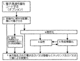
本発明の別の好ましい実施形態によれば、生体互換性インプラントを製造するための方法が更に提供され、該方法は、生体互換性材料から生体互換性インプラントを形成し、湿った環境で、走査型電子顕微鏡内で該生体互換性インプラントの少なくとも一部分を検査し、該検査工程の結果を分析し、該分析工程の結果に従って、検査された生体互換性インプラントを分類する、各工程を備える。 In accordance with another preferred embodiment of the present invention, there is further provided a method for manufacturing a biocompatible implant, the method forming a biocompatible implant from a biocompatible material and scanning in a moist environment. Inspecting at least a portion of the biocompatible implant in a scanning electron microscope, analyzing the results of the inspection process, and classifying the tested biocompatible implant according to the results of the analysis process.
本発明の別の好ましい実施形態によれば、上記検査工程は、上記少なくとも一部分を備えるサンプルを、湿った環境の標本エンクロージャ内に導入し、走査型電子顕微鏡の標本エンクロージャ内の該サンプルを走査し、これにより、該サンプルを視覚化する、各工程を備える。 According to another preferred embodiment of the present invention, the inspection step introduces the sample comprising the at least part into a specimen enclosure in a wet environment and scans the sample in the specimen enclosure of a scanning electron microscope. This comprises the steps of visualizing the sample.
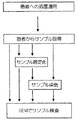
本発明の更に別の好ましい実施形態によれば、微生物学的実体の検出、同定又は特徴化のための方法が提供され、該方法は、少なくとも1つの微生物学的実体を含む、湿ったサンプルを取得し、走査型電子顕微鏡内で、湿ったサンプルを、水の蒸気圧を超える圧力により特徴付けられる環境内に存在する間に走査し、該走査工程の結果を分析する、各工程を備える。 According to yet another preferred embodiment of the present invention, there is provided a method for the detection, identification or characterization of a microbiological entity, the method comprising a wet sample comprising at least one microbiological entity. Each step comprises acquiring and scanning a wet sample in a scanning electron microscope while existing in an environment characterized by a pressure above the vapor pressure of water and analyzing the results of the scanning process.
好ましくは、上記走査工程は、少なくとも1つの微生物学的実体を含む、湿ったサンプルを、湿った環境の標本エンクロージャ内に導入し、走査型電子顕微鏡内で標本エンクロージャ内の湿ったサンプルを走査し、これにより、該湿ったサンプルを視覚化する、各工程を備える。 Preferably, the scanning step introduces a wet sample containing at least one microbiological entity into a specimen enclosure in a wet environment and scans the wet sample in the specimen enclosure within a scanning electron microscope. This comprises the steps of visualizing the wet sample.
本発明の好ましい実施形態によれば、上記湿ったサンプルは、尿を含む。代替例として、湿ったサンプルは、排泄物を含む。これに加えて、湿ったサンプルは、血液を含む。これに加えて又は代替として、湿ったサンプルは、唾液を含む。本発明の別の好ましい実施形態によれば、湿ったサンプルは、呼吸器系の洗浄物を含む。加えて、湿ったサンプルは、生体検査組織を含む。代替として、湿ったサンプルは、環境サンプルを含む。これに加えて又は代替として、湿ったサンプルは、脳脊髄流体を含む。本発明の更に別の好ましい実施形態によれば、湿ったサンプルは、土壌サンプルを含む。代替として、湿ったサンプルは、食物を含む。これに加えて、湿ったサンプルは、工業製品を含む。代替として又はこれに加えて、湿ったサンプルは、医療装置、工業装置又は家庭内装置を含む。 According to a preferred embodiment of the invention, the wet sample comprises urine. As an alternative, the wet sample contains excreta. In addition to this, the wet sample contains blood. In addition or alternatively, the wet sample contains saliva. According to another preferred embodiment of the present invention, the wet sample comprises a respiratory system wash. In addition, the wet sample contains biopsy tissue. Alternatively, the wet sample includes an environmental sample. In addition or alternatively, the wet sample contains cerebrospinal fluid. According to yet another preferred embodiment of the invention, the wet sample comprises a soil sample. Alternatively, the wet sample contains food. In addition to this, wet samples contain industrial products. Alternatively or in addition, the wet sample includes a medical device, an industrial device or a domestic device.
本発明の好ましい実施形態によれば、本方法は、サンプルを特異的に染色する工程を更に備える。これに加えて、本方法は、微生物学的実体を化学物質で処理する工程を更に備える。代替として又はこれに加えて、本方法は、微生物学的実体に放射を印加する工程を更に備える。これに加えて又は代替として、分析工程は、微生物学的実体の形態を分析する工程を含む。 According to a preferred embodiment of the present invention, the method further comprises the step of specifically staining the sample. In addition, the method further comprises the step of treating the microbiological entity with a chemical. Alternatively or additionally, the method further comprises the step of applying radiation to the microbiological entity. In addition or alternatively, the analyzing step comprises analyzing the morphology of the microbiological entity.
本発明の更に別の好ましい実施形態によれば、生体膜を特徴付けるための方法が提供され、該方法は、生体膜の湿ったサンプルを取得し、走査型電子顕微鏡内で該生体膜の湿ったサンプルを走査し、該走査工程の結果を分析する、各工程を備える。 In accordance with yet another preferred embodiment of the present invention, a method for characterizing a biological membrane is provided, the method obtaining a wet sample of the biological membrane and wetting the biological membrane in a scanning electron microscope. Each step includes scanning the sample and analyzing the results of the scanning step.
好ましくは、上記走査工程は、生体膜を含む、湿ったサンプルを湿った環境の標本エンクロージャ内に導入し、走査型電子顕微鏡内の湿った標本エンクロージャ内の湿ったサンプルを走査し、これにより該湿ったサンプルを視覚化する、各工程を備える。 Preferably, the scanning step introduces a wet sample, including a biological membrane, into a wet environment specimen enclosure and scans the wet sample in the wet specimen enclosure in a scanning electron microscope, thereby Each step comprises visualizing the wet sample.
本発明の更に別の好ましい実施形態によれば、サンプルを視覚化する方法が提供され、該方法は、サンプルを取得し、走査型電子顕微鏡内の湿った環境で該サンプルを、水の蒸気圧を超える圧力により特徴付けられる環境内に存在する間に、中間の凝固工程、被覆工程及びスライス切り工程無しに走査し、これによって該サンプルを視覚化する、各工程を備える。 In accordance with yet another preferred embodiment of the present invention, a method is provided for visualizing a sample, the method obtaining the sample and subjecting the sample to a vapor pressure of water in a moist environment within a scanning electron microscope. Each step of scanning without intermediate coagulation, coating and slicing steps, thereby visualizing the sample while present in an environment characterized by pressures above.
本発明の別の好ましい実施形態によれば、サンプルを視覚化する方法が更に提供され、該方法は、サンプルを取得し、走査型電子顕微鏡内の湿った環境で該サンプルを、水の蒸気圧を超える圧力により特徴付けられる環境内に存在する間に、走査前に形態的に衝撃を加えること無しに走査する、各工程を備える。 In accordance with another preferred embodiment of the present invention, there is further provided a method of visualizing a sample, the method acquiring the sample and subjecting the sample to the vapor pressure of water in a moist environment within a scanning electron microscope. Each step comprises scanning without morphological impact prior to scanning while in an environment characterized by a pressure greater than.
本発明の更に別の好ましい実施形態によれば、サンプルを視覚化する方法が更に提供され、該方法は、サンプルを取得し、走査型電子顕微鏡内の湿った環境で、該サンプルを、水の蒸気圧を超える圧力により特徴付けられる環境内に存在する間に、走査前の高々固定化及び染色工程に続いて走査する、各工程を備える。 In accordance with yet another preferred embodiment of the present invention, there is further provided a method of visualizing a sample, the method acquiring the sample and in a moist environment within a scanning electron microscope, Each step comprises scanning at most following immobilization and staining steps prior to scanning while in an environment characterized by pressures above the vapor pressure.
本発明のなお別の好ましい実施形態によれば、サンプルを視覚化する方法が更に提供され、該方法は、サンプルを取得し、走査型電子顕微鏡内の湿った環境で、該サンプルを、水の蒸気圧を超える圧力により特徴付けられる環境内に存在する間に、走査前の高々少なくとも1つの水成溶液を用いた処理に続いて走査する、各工程を備える。 In accordance with yet another preferred embodiment of the present invention, there is further provided a method for visualizing a sample, the method acquiring the sample, and in a moist environment within a scanning electron microscope, Each step comprises scanning following treatment with at least one aqueous solution prior to scanning while in an environment characterized by a pressure above the vapor pressure.
本発明の更に別の好ましい実施形態によれば、サンプルを視覚化する方法が更に提供され、該方法は、サンプルを取得し、走査型電子顕微鏡内の湿った環境で、該サンプルを、水の蒸気圧を超える圧力により特徴付けられる環境内に存在する間に、走査前に非水成溶液で処理されること無しに走査する、各工程を備える。 In accordance with yet another preferred embodiment of the present invention, there is further provided a method of visualizing a sample, the method acquiring the sample and in a moist environment within a scanning electron microscope, Each step comprises scanning without being treated with a non-aqueous solution prior to scanning while in an environment characterized by a pressure above the vapor pressure.
本発明の別の好ましい実施形態によれば、サンプルを視覚化する方法が更に提供され、該方法は、20ミクロンを超える厚さのサンプルを取得し、走査型電子顕微鏡内で、該サンプルを、水の蒸気圧を超える圧力により特徴付けられる環境内に存在する間に走査する、各工程を備える。 In accordance with another preferred embodiment of the present invention, there is further provided a method of visualizing a sample, the method obtaining a sample having a thickness of greater than 20 microns, the sample being scanned in a scanning electron microscope, Each step is scanned while existing in an environment characterized by a pressure above the vapor pressure of water.
本発明の更に別の好ましい実施形態によれば、脂肪組織を検査する方法が提供され、該方法は、脂肪組織のサンプルを取得し、走査型電子顕微鏡内で、該脂肪組織のサンプルを、水の蒸気圧を超える圧力により特徴付けられる環境内に存在する間に走査する、各工程を備える。 According to yet another preferred embodiment of the present invention, a method for examining adipose tissue is provided, the method comprising obtaining a sample of adipose tissue and subjecting the adipose tissue sample to water in a scanning electron microscope. Each step comprises scanning while present in an environment characterized by a pressure above the vapor pressure.
好ましくは、上記サンプルは、走査前に染色されていない。
本発明の更に別の好ましい実施形態によれば、脂肪組織を検査する方法が更に提供され、該方法は、脂肪組織のサンプルを取得し、走査型電子顕微鏡内で、該脂肪組織のサンプルを、該サンプルが走査前に染色されること無しに、走査する、各工程を備える。
Preferably, the sample is not stained prior to scanning.
According to yet another preferred embodiment of the present invention, there is further provided a method for examining adipose tissue, wherein the method obtains a sample of adipose tissue and the sample of adipose tissue is obtained in a scanning electron microscope. Each step comprises scanning the sample without staining prior to scanning.
本発明の別の好ましい実施形態によれば、サンプルを視覚化する方法が更に提供され、該方法は、走査型電子顕微鏡内で、サンプルを、水の蒸気圧を超える圧力により特徴付けられる環境内に存在する間に走査する工程を備え、走査型電子顕微鏡のステージに対してサンプルが移動すること無く、25平方ミリメートルを超えるサンプルの面積に亘って、走査工程が実行される。 In accordance with another preferred embodiment of the present invention, there is further provided a method of visualizing a sample, wherein the method is performed in a scanning electron microscope in an environment characterized by a pressure above the vapor pressure of water. The scanning step is performed over an area of the sample exceeding 25 square millimeters without moving the sample relative to the stage of the scanning electron microscope.
本発明のなお別の好ましい実施形態によれば、細胞外基質を検査する方法が提供され、該方法は、細胞外基質のサンプルを取得し、走査型電子顕微鏡内で、該細胞外基質のサンプルを、水の蒸気圧を超える圧力により特徴付けられる環境内に存在する間に走査する、各工程を備える。 According to yet another preferred embodiment of the present invention, a method for examining an extracellular matrix is provided, wherein the method obtains a sample of the extracellular matrix and the sample of the extracellular matrix in a scanning electron microscope Are scanned while present in an environment characterized by a pressure above the vapor pressure of water.
本発明のなお別の好ましい実施形態によれば、皮覆組織を検査する方法が提供され、該方法は、皮覆組織のサンプルを取得し、走査型電子顕微鏡内で、皮覆組織のサンプルを、水の蒸気圧を超える圧力により特徴付けられる環境内に存在する間に走査する、各工程を備える。 According to yet another preferred embodiment of the present invention, a method for inspecting skin tissue is provided, wherein the method obtains a skin tissue sample and in a scanning electron microscope the skin tissue sample is obtained. Scanning each while in an environment characterized by a pressure above the vapor pressure of water.
本発明の別の好ましい実施形態によれば、腎臓組織を検査する方法が提供され、該方法は、腎臓組織のサンプルを取得し、走査型電子顕微鏡内で、該腎臓組織のサンプルを、水の蒸気圧を超える圧力により特徴付けられる環境内に存在する間に走査する、各工程を備える。 According to another preferred embodiment of the present invention, a method for examining kidney tissue is provided, wherein the method obtains a sample of kidney tissue, and in a scanning electron microscope, the sample of kidney tissue is subjected to water. Each step comprises scanning while existing in an environment characterized by a pressure above the vapor pressure.
本発明の更に別の好ましい実施形態によれば、生体検査組織を検査する方法が提供され、該方法は、生体検査組織のサンプルを取得し、走査型電子顕微鏡内で、該生体検査組織のサンプルを、水の蒸気圧を超える圧力により特徴付けられる環境内に存在する間に走査する、各工程を備える。 According to yet another preferred embodiment of the present invention, a method for inspecting a biopsy tissue is provided, wherein the method obtains a sample of a biopsy tissue and the sample of the biopsy tissue in a scanning electron microscope Are scanned while present in an environment characterized by a pressure above the vapor pressure of water.
本発明の更に別の好ましい実施形態によれば、生物学的材料を検査する方法が更に提供され、該方法は、生物学的材料を免疫標識形成し、走査型電子顕微鏡内で、該免疫標識形成された生物学的材料を、水の蒸気圧を超える圧力により特徴付けられる環境内に存在する間に走査する、各工程を備える。 In accordance with yet another preferred embodiment of the present invention, there is further provided a method of examining biological material, the method immunolabeling the biological material, and the immunolabeling in a scanning electron microscope Each step comprises scanning the formed biological material while it is in an environment characterized by a pressure above the vapor pressure of water.
本発明の更に別の好ましい実施形態によれば、組織を検査する方法が提供され、本方法は、組織を免疫標識形成し、走査型電子顕微鏡内で、該免疫標識形成された組織を、水の蒸気圧を超える圧力により特徴付けられる環境内に存在する間に走査する、各工程を備える。 In accordance with yet another preferred embodiment of the present invention, there is provided a method for examining tissue, wherein the method immunolabels tissue and the immunolabeled tissue is washed with water in a scanning electron microscope. Each step comprises scanning while present in an environment characterized by a pressure above the vapor pressure.
本発明の更に別の好ましい実施形態によれば、サンプルを検査する方法が更に提供され、該方法は、走査型電子顕微鏡内で、サンプルを、水の蒸気圧を超える圧力により特徴付けられる環境内に存在する間に走査し、該サンプルを光学顕微鏡を使用して検査する、各工程を備える。 In accordance with yet another preferred embodiment of the present invention, there is further provided a method for inspecting a sample, wherein the method is performed in a scanning electron microscope in an environment characterized by a pressure above the vapor pressure of water. Scanning, and inspecting the sample using an optical microscope.
本発明の別の好ましい実施形態によれば、化学物質又は化学物質の組み合わせにさらしたときの毒性効果を分析するための方法が提供され、該方法は、実験動物を、化学物質又は化学物質の組み合わせにさらし、実験動物からサンプルを取得し、走査型電子顕微鏡内で、実験動物からのサンプルを、水の蒸気圧を超える圧力により特徴付けられる環境内に存在する間に走査する、各工程を備える。 According to another preferred embodiment of the present invention, there is provided a method for analyzing toxic effects when exposed to a chemical or a combination of chemicals, the method comprising treating a laboratory animal with a chemical or chemical Each step of exposing the combination, obtaining a sample from the experimental animal, and scanning the sample from the experimental animal in a scanning electron microscope while present in an environment characterized by a pressure above the vapor pressure of water. Prepare.
本発明の更に別の好ましい実施形態によれば、環境条件にさらした後に続く毒性効果を分析する方法が更に提供され、該方法は、環境条件にさらされた少なくとも1つの個体を同定し、少なくとも1つの個体の少なくとも1つから少なくとも1つのサンプルを取得し、走査型電子顕微鏡内で、該少なくとも1つのサンプルを、水の蒸気圧を超える圧力により特徴付けられる環境内に存在する間に走査する、各工程を備える。 According to yet another preferred embodiment of the present invention, there is further provided a method of analyzing toxic effects following exposure to environmental conditions, the method identifying at least one individual exposed to environmental conditions, at least Obtain at least one sample from at least one of an individual and scan in the scanning electron microscope while present in an environment characterized by a pressure above the vapor pressure of water Each step is provided.
本発明のなお別の好ましい実施形態によれば、化学的実体を特徴付ける方法が更に提供され、該方法は、SEM互換性サンプルエンクロージャ内で化学的実体を細胞に印加し、走査型電子顕微鏡内で、該細胞を、水の蒸気圧を超える圧力により特徴付けられる環境内に存在する間に走査する、各工程を備える。 In accordance with yet another preferred embodiment of the present invention, there is further provided a method for characterizing a chemical entity, the method applying the chemical entity to a cell in a SEM compatible sample enclosure and in a scanning electron microscope. Scanning the cells while they are in an environment characterized by a pressure above the vapor pressure of water.
好ましくは、本方法は、細胞形状の変化を分析する工程を更に備える。これに加えて又は代替として、本方法は、細胞の細胞骨格を分析する工程を更に備える。加えて、本方法は、細胞の生態分子の分布を分析する工程を更に備える。 Preferably, the method further comprises analyzing the change in cell shape. In addition or alternatively, the method further comprises the step of analyzing the cytoskeleton of the cell. In addition, the method further comprises analyzing the distribution of cellular ecomolecules.
本発明の別の好ましい実施形態によれば、本方法は、サンプルの領域からのX線を検出し、該サンプル内で、ヨウ素、金属及びリンのうち少なくとも1つの存在を検出するため該X線を分析する、各工程を備える。好ましくは、本方法は、ヨウ素、金属及びリンのうち前記少なくとも1つの濃度を決定する工程を更に備える。 According to another preferred embodiment of the present invention, the method detects X-rays from a region of a sample and detects the presence of at least one of iodine, metal and phosphorus in the sample. Each step is analyzed. Preferably, the method further comprises the step of determining the concentration of said at least one of iodine, metal and phosphorus.
本発明の更に別の好ましい実施形態によれば、上記サンプルは、電子透過性で流体不透過性の膜を通過した電子により衝突される。加えて、本方法は、該サンプルを電子透過性で流体不透過性の膜に押し付ける工程を更に備える。 According to yet another preferred embodiment of the invention, the sample is bombarded by electrons that have passed through an electron permeable, fluid impermeable membrane. In addition, the method further comprises pressing the sample against an electron permeable, fluid impermeable membrane.
本発明は、添付図面と関連付けられた次の詳細な説明からより完全に理解され、認められるであろう。 The present invention will be understood and appreciated more fully from the following detailed description, taken in conjunction with the accompanying drawings, in which:
本発明は、非真空で湿った環境におけるサンプルの電子顕微鏡による検査のための方法に関する。より詳しくは、本発明は、重要な詳細構造を破壊して観察されるべきサンプルに擬似物を導入するおそれのある水置換及び臨界点乾燥を始めとする脱水処置を施す必要無しに、走査型電子顕微鏡でサンプルを視覚化するための方法に関する。本発明の方法を用いない場合、電子顕微鏡で試験されるべきサンプルは、真空又は真空に近い状態でしか移動することができない電子ビームによる妨げられないアクセスを可能にするため、真空又は真空に近い状態で保持されなければならない。 The present invention relates to a method for electron microscopic examination of a sample in a non-vacuum and humid environment. More particularly, the present invention provides a scanning type without the need for dehydration procedures such as water displacement and critical point drying, which may destroy important details and introduce mimetics into the sample to be observed. The invention relates to a method for visualizing a sample with an electron microscope. Without using the method of the present invention, the sample to be tested in the electron microscope is close to vacuum or vacuum in order to allow unobstructed access by an electron beam that can only be moved under vacuum or near vacuum. Must be kept in state.
本発明の方法は、走査されるべきサンプルがその中に配置されるところの、後述される新規なSEMサンプル容器を有利に用いている。サンプルの水和及び大気圧状態は、SEMステージに配置し、SEM走査チャンバーを退去させた後でさえも、維持される。 The method of the present invention advantageously uses a novel SEM sample container, described below, in which the sample to be scanned is placed. Sample hydration and atmospheric pressure conditions are maintained even after placement on the SEM stage and exiting the SEM scanning chamber.
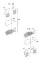
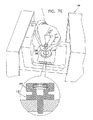
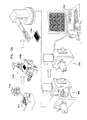
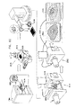
ここで、本発明の好ましい実施例に従って構成され、作動する、分解されたSEM互換性サンプル容器の、各々反対側に向いた簡略的な分解図である、図1A乃至図5Bを参照する。図1A及び図1Bに示されるように、SEM互換性サンプル容器は、閉鎖の容易さ及び速さを向上させるため配列された、参照番号100及び102により指し示された、第1及び第2の互いにねじ込まれるエンクロージャ要素を備えている。エンクロージャ要素100及び102は、好ましくは、プラスチックから成形され、導電性金属コーティングで被覆される。
Reference is now made to FIGS. 1A-5B, which are simplified exploded views, each directed to the opposite side, of an exploded SEM compatible sample container constructed and operative in accordance with a preferred embodiment of the present invention. As shown in FIGS. 1A and 1B, SEM-compatible sample containers are first and second indicated by
第1のエンクロージャ要素100は、好ましくは、液体サンプルエンクロージャを形成し、略中央アパーチャ106を持つベース表面104を有する。図2A及び図2Bに詳細に示される、電子ビーム透過性で流体不透過性の膜サブアッセンブリ108は、図3A、3B及び図5A、5Bに示されるように、アパーチャ106に対向してこれを覆って、エンクロージャ要素100の内部に着座している。エンクロージャ要素100内に適切に配置されたサブアッセンブリ108を備えるサンプル皿部は、図3A乃至図5Bに示されるように、参照番号109により指し示されている。
The
更に図2A及び図2Bを参照すると、電子ビーム透過性で流体不透過性の膜110が、接着剤により、機械式支持格子112に接着される。該膜110は、アメリカ合衆国、UT、オレムのモックステック社から市販されている、カタログ番号LWN00033等のポリイミド膜を含むのが好ましい。格子112は、図面で縮尺通りには示されておらず、該格子としては、アメリカ合衆国、ニューヨークのコートランドのバックビーメアズから市販されている、カタログ番号BM0090−01が好ましい。接着剤は、アメリカ合衆国、NJのグランベリーのノーランドプロダクツ社から市販されており、カタログ番号NOA61であるのが好ましい。液体サンプルエンクロージャ形成リング114は、好ましくは、例えばアメリカ合衆国、NJのグランベリーのノーランドプロダクツ社から市販されているカタログ番号NOA61の接着剤により、電子ビーム透過性で流体不透過性の膜110に接着されている。リング114は、スペイン、バルセロナ市のイルペンから市販されている、例えばカタログ番号692106001000等のPMMA(ポリメチルメタクリレート)から形成されるのが好ましく、約20マイクロリットルの体積で約2mmの高さを備えた液体サンプルエンクロージャを画定するのが好ましい。好ましくは、リング114は、傾斜壁を有する液体サンプルエンクロージャ116を画定するように構成される。
Still referring to FIGS. 2A and 2B, an electron beam permeable, fluid
代替例として、膜110は、ポリアミド、ポリアミド−イミド、ポリエチレン、ポリプロピレン、「パーロディオン」、「コロディオン」、「カプトン」、「フォームバー」、「ビニレック」、「バットバー」、「ピオロフォルム」、「パリレーネ」、二酸化シリコン、一酸化シリコン、又は、カーボン、或いは、前掲したものの任意の組み合わせ、又は、他の任意の適切な材料から形成されてもよい。
As an alternative, the
Oリング118は、リング114と、第2のエンクロージャ要素102の内部表面との間に配置されているのが好ましい。Oリング118は、エンクロージャ要素100及び102が緊密なねじ込み係合であるとき、要素100及び102のねじ込み係合が密封係合であるべき必要性を無くすように作用する。
The O-
第2のエンクロージャ要素102には、走査型電子顕微鏡の標本ステージの適切な凹部(図示せず)に着座するように配列された、略中央スタブ122が形成されるのが好ましい。図1A乃至図10に示される容器は、従来の走査型電子顕微鏡の従来のスタブ用凹部に適合するサイズで働き、それが何であれ、変形する必要はないことが、本発明の特別な特徴である。スタブの様々な形態及びサイズを、様々な走査型電子顕微鏡に適合するように提供することができることが認められよう。
The
エンクロージャ要素100及び102は、容器を、適切な多重容器ホルダー内に容易に着座させることを可能にし、更にユーザーがエンクロージャ要素100及び102をねじ込み開閉することを援助するため、径方向に延在する夫々の位置決め保持突起部124及び125が設けられるのが好ましい。好ましくは、各々のエンクロージャ要素100及び102上の突起部124及び125の相対的な方位角方向の配置は、図4A及び図4Bに示されるように、これら突起部間の相対的な方位角方向の整列が、要素間のねじ込み閉鎖の所望の度合いを指し示すようになっているのが好ましい。
本発明の別の実施例では、サンプル皿部がエンクロージャ100及び102を備えていてもよいことが認められよう。
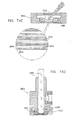
ここで、図1A乃至図5BのSEM互換性サンプル容器の作動態様を作動の3段階で各々示した3つの断面図である、図6A、6B及び6Cを参照する。図6Aは、エンクロージャ要素100及び102をねじ込み閉鎖する前の図1Bに示される配位で配列されている、液体サンプル130を蓄えた図1A乃至図5Bの容器を示している。なお、液体サンプルは、表面張力に起因して、液体サンプルエンクロージャ116からは流れ出ない。電子ビーム透過性で流体不透過性の膜110が、図6Aにおいて、略平坦であるように示されている。
It will be appreciated that in other embodiments of the invention, the sample pan may include
Reference is now made to FIGS. 6A, 6B, and 6C, which are three cross-sectional views illustrating the operational aspects of the SEM compatible sample container of FIGS. 1A-5B, respectively, in three stages of operation. FIG. 6A shows the container of FIGS. 1A-5B storing a
図6Bは、周囲からの液体サンプルエンクロージャ116の密封を生成するエンクロージャ要素100及び102の間の完全なねじ込み係合に続く中間状態にある、図6Aの容器を示している。電子ビーム透過性で流体不透過性の膜110と、その支持格子112とが、この態様におけるその密封の結果生じた液体サンプルエンクロージャ116の圧力形成に起因して、外方にしなっていることが見て取れる。
FIG. 6B shows the container of FIG. 6A in an intermediate state following a complete screwed engagement between
図6Cは、典型的には、10−2〜10−6ミリバールの真空でSEMの脱ガス環境に配置されたときの図6Bの容器を示している。この環境では、電子ビーム透過性で流体不透過性の膜110と支持格子112とが、図6Bの周囲環境に配置されたときよりも、より大きい度合いで外方にしなっていることが見て取れる。更には、電子ビーム透過性で流体不透過性の膜110は、図6Bの周囲環境で生じたものよりも大きい度合いで格子112の隙間を通って隙間内に入り込もうとしていることが理解できる。
FIG. 6C shows the container of FIG. 6B when placed in a SEM degassing environment with a vacuum of typically 10 −2 to 10 −6 mbar. In this environment, it can be seen that the electron beam transmissive and fluid
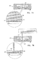
ここで、図1A乃至図6CのSEM互換性サンプル容器を使用した、細胞成長、液体除去、液体追加、密封及びSEMへの挿入の各状態の簡略断面図である、図7A、7B、7C、7D及び7Eを参照する。典型的な細胞培養状況を示す、図7Aを参照すると、サブアッセンブリ108を内部に配置させたエンクロージャ要素100は、図1Aに示された配置態様にあり、液体媒体142内の細胞140は液体サンプルエンクロージャ116内に配置され、これらの細胞140が、電子ビーム透過性で流体不透過性の膜110に接触して横たわっている。
Here, FIGS. 7A, 7B, 7C are simplified cross-sectional views of cell growth, liquid removal, liquid addition, sealing, and insertion into the SEM using the SEM compatible sample containers of FIGS. 1A-6C. See 7D and 7E. Referring to FIG. 7A, which illustrates a typical cell culture situation, the
図7Bは、典型的には吸引によって液体サンプルエンクロージャ116から液体を除去した状態を示し、図7Cは、液体サンプルエンクロージャ116に液体を追加した状態を示している。液体の除去及び追加を多数回に亘って液体サンプルエンクロージャ116内のサンプルに関して実行してもよい。好ましくは、液体除去及び追加のため用いられる装置は、電子ビーム透過性で流体不透過性の膜110の意図しない破裂を防止するように、設計され、備え付けられるのがよい。
FIG. 7B shows a state in which liquid is removed from the
図7Dは、図7Cに示される細胞140を液体媒体142内に含む容器の閉鎖状態を示している。図7Eは、SEM146のステージ144上に挿入される閉鎖容器を図1Bの配位で示している。容器の配位が図7Eに示されたものとは反対であるSEMが存在することが認められよう。
FIG. 7D shows a closed state of the container containing the
図7A乃至図7Dは、液体サンプルエンクロージャ116に関する液体の追加又は除去に拘わらず、サンプルを含む液体の少なくとも一部分が電子ビーム透過性で流体不透過性の膜110と接触したままとなる状況を例示している。この状況は、電子ビーム透過性で流体不透過性の膜110に、サンプルの一部が吸収され、そうでなければ、接着される状況を含んでいてもよい。サンプルを含む液体の例は、細胞、培養菌、血液、バクテリア及び無細胞材料を含んでいてもよい。
FIGS. 7A-7D illustrate a situation in which at least a portion of the liquid containing the sample remains in contact with the electron beam transparent and fluid
図1A乃至図6CのSEM互換性サンプル容器を使用した、電子ビーム透過性で流体不透過性の膜110と接触したサンプル含有液体、密封及びSEMへの挿入の各状態の簡略断面図である、図8A、8B及び8Cを参照する。図8A乃至図8Cは、サンプルを含む液体160の少なくとも一部分が電子ビーム透過性で流体不透過性の膜110と接触しているが、それに接着されていない状況を例示している。サンプルを含む液体の例には、例えば、ミルク、化粧用クリーム、ペイント、インク、及び、液体形態の薬剤等、様々な乳濁液及び懸濁液がある。図8A乃至図8Bで、サブアッセンブリ108を内部に配置させたエンクロージャ要素10は、図1Aに示される配位にあることが見て取れよう。
FIG. 7 is a simplified cross-sectional view of a sample-containing liquid in contact with an electron beam permeable fluid
図8Bは、サンプル160を含む容器の閉鎖状態を示している。図8Cは、SEM146のステージ144上に挿入された、図1Bの配位にある、閉鎖容器を示している。容器の配位が図8Cに示されたものとは反対であるSEMが存在することが認められよう。
FIG. 8B shows the closed state of the container containing the
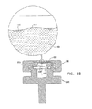
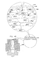
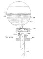
ここで、図1A乃至図6CのSEM互換性サンプル容器を使用した、サンプルのSEM検査の簡略図及び断面図である、図9を参照する。図9に示されるように、参照番号170により指し示された容器は、SEMにより発生された電子ビーム172が電子ビーム透過性で流体不透過性の膜110を通過し、容器170内のサンプル174を含む液体に照射されように、SEM146のステージ144上に配置されている。サンプル174からの後方散乱電子は、電子ビーム透過性で流体不透過性の膜110を通過し、SEMの一部を形成する検出器176により検出される。例えば2次電子検出器等の1つ以上の追加の検出器を設けてもよい。電子ビーム励起に起因してサンプル174により放射されるX線放射を検出するためのX線検出器(図示せず)を設けてもよい。
Reference is now made to FIG. 9, which is a simplified and cross-sectional view of SEM inspection of a sample using the SEM compatible sample container of FIGS. 1A-6C. As shown in FIG. 9, the container designated by
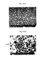
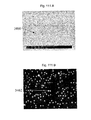
ここで、本発明の好ましい実施例に係る容器170内のサンプル174との電子ビーム相互作用の詳細を概略的に示す図10を追加的に参照する。なお、本発明は、図10に示されるように、それらの平均的な原子番号により互いから区別される特徴群の高いコントラストの画像形成を可能にしている。図10では、比較的高い平均原子番号を有する、細胞核180は、周囲の核質182よりも電子をより大きく後方散乱させることが示されている。
Reference is now additionally made to FIG. 10, which schematically shows details of electron beam interaction with the
なお、本発明の好ましい実施例によれば、約2ミクロンまでの深さのサンプル内部の画像形成は、図10に示されるように、50KeVより低いエネルギーレベルを有する電子に対して達成可能であり、電子ビーム透過性で流体不透過性の膜110より下方に位置する細胞核180が画像形成される。
It should be noted that according to a preferred embodiment of the present invention, imaging within a sample up to about 2 microns deep can be achieved for electrons having an energy level lower than 50 KeV, as shown in FIG. The cell nuclei 180 located below the
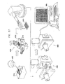
ここで、本発明の別の好ましい実施例に従って構成され、作動する、分解された走査型電子顕微鏡(SEM)の互換性サンプル容器の、各々反対側に向いた簡略的な分解図である、図11A乃至図15Bを参照する。図11A及び図11Bに示されるように、SEM互換性サンプル容器は、閉鎖の容易さ及び速さを向上させるように配列された、参照番号200及び202により指し示された、第1及び第2の相互にねじ込まれるエンクロージャ要素を備えている。エンクロージャ要素200及び202は、プラスチックから成形され、導電性金属コーティングで被覆されるのが好ましい。
Here, a simplified exploded view, each directed to the opposite side, of a disassembled scanning electron microscope (SEM) compatible sample container constructed and operative in accordance with another preferred embodiment of the present invention, FIG. Refer to FIGS. 11A to 15B. As shown in FIGS. 11A and 11B, the SEM compatible sample containers are first and second indicated by
第1のエンクロージャ要素200は、好ましくは、液体サンプルエンクロージャを形成し、略中央アパーチャ206を持つベース表面204を有する。図12A及び図12Bに詳細に示される、電子ビーム透過性で流体不透過性の膜サブアッセンブリ208は、図13A、13B及び図15A、15Bに示されるように、アパーチャ206に対向してこれを覆って、エンクロージャ要素200の内部に着座している。エンクロージャ要素200内に適切に配置されたサブアッセンブリ208を備えるサンプル皿部は、図13A乃至図15Bに示されるように、参照番号209により指し示されている。
The
更に図12A及び図12Bを参照すると、電子ビーム透過性で流体不透過性の膜210が、接着剤により、機械式支持格子212に接着される。該膜210は、アメリカ合衆国、UT、オレムのモックステック社から市販されている、カタログ番号LWN00033等のポリイミド膜を含むのが好ましい。格子212は、図面で縮尺通りには示されておらず、該格子としては、アメリカ合衆国、ニューヨークのコートランドのバックビーメアズから市販されている、カタログ番号BM0090−01が好ましい。接着剤は、アメリカ合衆国、NJのグランベリーのノーランドプロダクツ社から市販されており、カタログ番号NOA61であるのが好ましい。液体サンプルエンクロージャ形成リング214は、好ましくは、例えばアメリカ合衆国、NJのグランベリーのノーランドプロダクツ社から市販されているカタログ番号NOA61の接着剤により、電子ビーム透過性で流体不透過性の膜210に接着されている。リング214は、スペイン、バルセロナ市のイルペンから市販されている、例えばカタログ番号692106001000等のPMMA(ポリメチルメタクリレート)から形成されるのが好ましく、約20マイクロリットルの体積で約2mmの高さを備えた液体サンプルエンクロージャを画定するのが好ましい。好ましくは、リング214は、傾斜壁を有する液体サンプルエンクロージャ216を画定するように構成される。
Still referring to FIGS. 12A and 12B, an electron beam permeable, fluid
ダイヤフラム218が、リング214と、第2のエンクロージャ要素202の内側表面219との間に配置されるのが好ましい。好ましくは、ダイヤフラム218は、Oリング部220から一体成形され、該Oリング部220には、伸張可能シート部221が密封されている。ダイヤフラム218は、約50のショア硬度を有するシリコンゴムから成形されるのが好ましく、シート部221は、0.2〜0.3mmの厚さを有するのが好ましい。ダイヤフラム218は、エンクロージャ要素200及び202が、緊密なねじ込み係合にあるとき、要素200及び202のねじ込み係合が密封係合であるべき必要性を無くすように、並びに、その動的圧力及び静的圧力を提供するように作動する。
A
第2のエンクロージャ要素202には、走査型電子顕微鏡の標本ステージの適切な凹部(図示せず)に着座するように配列された、貫通ボア223を有する略中央スタブ222が形成されるのが好ましい。ボア223は、ダイヤフラム218の一方の側と(SEM)互換性サンプル容器が配置されている環境との間に流体連通チャンネルを形成することにより、ダイヤフラム218が圧力リリーフを提供することを可能にする。図11A乃至図20に示される容器は、従来の走査型電子顕微鏡の従来のスタブ用凹部に適合するサイズで働き、それが何であれ、変形する必要はないことが、本発明の特別な特徴である。スタブの様々な形態及びサイズを、様々な走査型電子顕微鏡に適合するように提供することができることが認められよう。
The
エンクロージャ要素200及び202は、容器を、適切な多重容器ホルダー内に容易に着座させることを可能にし、更にユーザーがエンクロージャ要素200及び202をねじ込み開閉することを援助するため、径方向に延在する夫々の位置決め保持突起部224及び225が設けられるのが好ましい。好ましくは、各々のエンクロージャ要素200及び202上の突起部224及び225の相対的な方位角方向の配置は、図14A及び図14Bに示されるように、これら突起部間の相対的な方位角方向の整列が、要素間のねじ込み閉鎖の所望の度合いを指し示すようになっているのが好ましい。
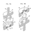
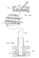
ここで、図11A乃至図15BのSEM互換性サンプル容器の作動態様を作動の3段階で各々示した3つの断面図である、図16A、16B及び16Cを参照する。図16Aは、エンクロージャ要素200及び202をねじ込み閉鎖する前に、図11Bに示された配位で配列されている、液体サンプル230を蓄えた図11A乃至図15Bの容器を示している。なお、液体サンプルは、表面張力に起因して、液体サンプルエンクロージャ216からは流れ出ない。電子ビーム透過性で流体不透過性の膜210が、図16Aにおいて、略平坦であるように示されている。
Reference is now made to FIGS. 16A, 16B, and 16C, which are three cross-sectional views illustrating the operational aspects of the SEM compatible sample container of FIGS. 11A-15B, respectively, in three stages of operation. FIG. 16A shows the container of FIGS. 11A-15B with the
図16Bは、周囲からの液体サンプルエンクロージャ216の密封を生成するエンクロージャ要素200及び202の間の完全なねじ込み係合に続く中間状態にある、図16Aの容器を示している。ダイヤフラム218が、この態様におけるその密封の結果生じた液体サンプルエンクロージャ216の圧力形成に起因して、外方にしなっていることが見て取れる。本実施例では、電子ビーム透過性で流体不透過性の膜210及びその支持格子212も、この態様におけるその密封の結果生じた液体サンプルエンクロージャ116の圧力形成に起因して、外方にしなっているが、ダイヤフラム218の作用に起因して、かなりより小さい程度にしか、しなっていない。これは、図16Bと図6Bとを比較することにより、理解することができる。
FIG. 16B shows the container of FIG. 16A in an intermediate state following a complete screwed engagement between
図16Cは、典型的には、10−2〜10−6ミリバールの真空でSEMの脱ガス環境に配置されたときの図16Bの容器を示している。この環境では、ダイヤフラム218が、図16Bの周囲環境のときよりもより大きい度合いで外方にしなり、電子ビーム透過性で流体不透過性の膜210と支持格子212とが、図16Bの周囲環境に配置されたときよりも、より大きい度合いで外方にしなっているが、ダイヤフラム218の作用に起因して、図6Cの実施例のときよりも、かなり小さい度合いでしかしなっていないことが見て取れる。これは、図16Cと図6Cとを比較することにより、理解することができる。
FIG. 16C shows the container of FIG. 16B when placed in a SEM degassing environment with a vacuum of typically 10 −2 to 10 −6 mbar. In this environment, the
なお、電子ビーム透過性で流体不透過性の膜210は、図16Bの周囲環境で生じたものよりも大きい度合いで格子212の隙間を通って隙間内に入り込もうとしているが、ダイヤフラム218の作用に起因して、図6Cの実施例のときよりもかなり小さい度合いでしかしなっていないことが理解できる。これは、図16Cと図6Cとを比較することにより、理解することができる。
Note that the electron beam transmissive and fluid
ここで、図11A乃至図16CのSEM互換性サンプル容器を使用した、細胞成長、液体除去、液体追加、密封及びSEMへの挿入の各状態の簡略断面図である、図17A、17B、17C、17D及び17Eを参照する。図7Aと同一で、典型的な細胞の培養状況を示す、図17Aを参照すると、サブアッセンブリ208を内部に配置させたエンクロージャ要素200が、図11Aに示される配位にあり、液体媒体242中の細胞240が、液体サンプルエンクロージャ216内に配置され、細胞240が、電子ビーム透過性で流体不透過性の膜210に接触して横たわっていることが示されている。
Here, FIGS. 17A, 17B, and 17C are simplified cross-sectional views of cell growth, liquid removal, liquid addition, sealing, and insertion into the SEM using the SEM compatible sample containers of FIGS. Reference is made to 17D and 17E. Referring to FIG. 17A, which is identical to FIG. 7A and shows a typical cell culture situation, the
図7Bと同一の図17Bは、典型的には吸引により、液体サンプルエンクロージャ216からの液体の除去を示し、図7Cと同一の図17Cは、液体サンプルエンクロージャ216への液体の追加を示している。液体の除去及び追加を多数回に亘って液体サンプルエンクロージャ216内のサンプルに関して実行してもよい。好ましくは、液体除去及び追加のため用いられる装置は、電子ビーム透過性で流体不透過性の膜210の意図しない破裂を防止するように、設計され、備え付けられるのがよい。
FIG. 17B, identical to FIG. 7B, shows the removal of liquid from the
図17Dは、図17Cに示される細胞240を液体媒体242内に含む容器の閉鎖状態を示している。図17Eは、SEM246のステージ244上に挿入される閉鎖容器を図11Bの配位で示している。容器の配位が図17Eに示されたものとは反対であるSEMが存在することが認められよう。
FIG. 17D shows the closed state of the container containing the
図17A乃至図17Dは、液体サンプルエンクロージャ216に関する液体の追加又は除去に拘わらず、サンプルを含む液体の少なくとも一部分が電子ビーム透過性で流体不透過性の膜210と接触したままとなる状況を例示している。この状況は、電子ビーム透過性で流体不透過性の膜210に、サンプルの一部が吸収され、そうでなければ、接着される状況を含んでいてもよい。サンプルを含む液体の例は、細胞、培養菌、血液、バクテリア及び無細胞材料を含んでいてもよい。
FIGS. 17A-17D illustrate a situation where at least a portion of the liquid containing the sample remains in contact with the electron beam transmissive and fluid
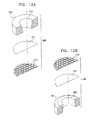
図11A乃至図16CのSEM互換性サンプル容器を使用した、電子ビーム透過性で流体不透過性の膜210と接触したサンプル含有液体、密封及びSEMへの挿入の各状態の簡略断面図である、図18A、18B及び18Cを参照する。図18A乃至図18Cは、サンプルを含む液体260の少なくとも一部分が電子ビーム透過性で流体不透過性の膜210と接触しているが、それに接着されていない状況を例示している。サンプルを含む液体の例には、例えば、ミルク、化粧用クリーム、ペイント、インク、及び、液体形態の薬剤等、様々な乳濁液及び懸濁液がある。図18A乃至図18Bで、サブアッセンブリ208を内部に配置させた、エンクロージャ要素200は、図11Aに示される配位にあることが見て取れよう。図18Aは図8Aと同一である。
FIG. 17 is a simplified cross-sectional view of a sample-containing liquid in contact with an electron beam permeable fluid
図18Bは、サンプル260を含む容器の閉鎖状態を示している。図18Cは、SEM246のステージ244上に挿入された、図11Bの配位にある、閉鎖容器を示している。容器の配位が図18Cに示されたものとは反対であるSEMが存在することが認められよう。
FIG. 18B shows the closed state of the container containing the
ここで、図11A乃至図16CのSEM互換性サンプル容器を使用した、サンプルのSEM検査の簡略図及び断面図である、図19を参照する。図19に示されるように、参照番号270により指し示された容器は、SEMにより発生された電子ビーム272が電子ビーム透過性で流体不透過性の膜210を通過し、容器270内のサンプル274を含む液体に照射されように、SEM246のステージ244上に配置されている。サンプル274からの後方散乱電子は、電子ビーム透過性で流体不透過性の膜210を通過し、SEMの一部を形成する検出器276により検出される。例えば2次電子検出器等の1つ以上の追加の検出器を設けてもよい。電子ビーム励起に起因してサンプル274により放射されるX線放射を検出するためのX線検出器(図示せず)を設けてもよい。
Reference is now made to FIG. 19, which is a simplified and cross-sectional view of a sample SEM inspection using the SEM compatible sample container of FIGS. 11A-16C. As shown in FIG. 19, the container designated by
ここで、本発明の好ましい実施例に係る容器270内のサンプル274との電子ビーム相互作用の詳細を概略的に示す図20を追加的に参照する。なお、本発明は、図20に示されるように、それらの平均的な原子番号により互いから区別される特徴群の高いコントラストの画像形成を可能にしている。図20では、比較的高い平均原子番号を有する、細胞核280が、周囲の核質282よりも電子をより大きく後方散乱させることが示されている。
Reference is now additionally made to FIG. 20, which schematically shows details of electron beam interaction with a
なお、本発明の好ましい実施例によれば、約2ミクロンまでの深さのサンプル内部の画像形成は、図20に示されるように、50KeVより低いエネルギーレベルを有する電子に対して達成可能であり、電子ビーム透過性で流体不透過性の膜210より下方に位置する細胞核280が画像形成される。
Note that, according to a preferred embodiment of the present invention, imaging inside samples up to about 2 microns deep can be achieved for electrons having energy levels below 50 KeV, as shown in FIG. The cell nuclei 280 located below the
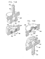
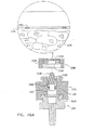
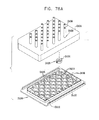
ここで、図1A乃至図20に示された型式のSEM互換性サンプル容器で使用する顕微鏡検査前の多重サンプルホルダーの簡略的な分解図である、図21A及び図21Bを参照する。更に、顕微鏡検査前の多重サンプルホルダーを、覆われていない状態、及び、覆われて組み立てられた状態で各々示した、簡略図である、図22A及び図22Bを参照する。 Reference is now made to FIGS. 21A and 21B, which are simplified exploded views of a multiple sample holder prior to microscopy for use with an SEM compatible sample container of the type shown in FIGS. 1A-20. Reference is further made to FIGS. 22A and 22B, which are simplified illustrations showing the multiple sample holders before microscopy, uncovered and covered and assembled, respectively.
図21A及び図21Bに示されるように、顕微鏡検査前の多重サンプルホルダーは、ベース部300と、頂部要素302と、カバー304と、を備えるのが好ましい。好ましくは、カバー304が顕微鏡検査前の多重サンプルホルダーの内部に無菌状態を維持するため設けられる。
As shown in FIGS. 21A and 21B, the multiple sample holder before microscopic examination preferably includes a
ベース部300は、好ましくは、プラスチック材料から射出成形され、容器支持収容部306の列を形成する。各々の容器支持収容部306は、光透明底部壁を有する凹部308により形成されるのが好ましい。該光透明底部壁を通して光学顕微鏡の検査を実行することができる。図1A乃至図8Cで参照番号100により指し示されたエンクロージャ要素で、各凹部308に隣接して、図1A乃至図4Bで参照番号124により指し示された突起部を収容するように配置された、一対の互いに整列した対の直立相互間隔突起部310が形成され、これにより方位角方向の整列を固定するのが好ましい。
ベース部300は、顕微鏡検査前の多重サンプルホルダーの内部で所望レベルの湿度を維持するため使用される液体を保持するようになった、複数の液体リザーバー312を形成するのが好ましい。ベース部300は、床部320が形成されるのが好ましい。ベース部300の所望の配列で、図3A乃至図5Bの参照番号109により指し示されたサンプル皿部を保持するように、頂部要素302は、取り外し可能にベース部300とスナップ式に係合するため配列されている。頂部要素302には、容器支持収容部306で着座されたサンプル皿部109の上を横たわるように配列されたアパーチャ324の列を有する、平坦表面322が形成されている。アパーチャ324のサイズは、サンプル皿部109が通過することを防止するように、エンクロージャ要素100のサイズよりも小さくなるように選択されるのが好ましい。平坦表面322は、液体リザーバー312と連通するアパーチャ326を備えるのが好ましい。
The base 300 preferably forms a plurality of
頂部要素302は、位置決め案内部328と、ダミーアパーチャ330とを更に提供する。ダミーアパーチャは、図23A及び図23Bを参照して後述されるように、これと連結された吸引装置により使用するため設けられている。組み合わせダミーアパーチャ332も設けられている。各アパーチャ332の一部分だけが液体リザーバー312を覆い、各アパーチャ332の残りが、吸引装置のためのダミーアパーチャとして機能する。
The
カバー304が、顕微鏡検査前の多重サンプルホルダーの内部の無菌状態を維持するため提供される。カバー304は、図22Bに示されるように光に対して透明であるのが好ましい。図21A乃至図22Bの顕微鏡検査前の多重サンプルホルダーは、光学顕微鏡、遠心分離機及び自動位置決め装置等の従来の細胞生物学的設備と互換性があるように寸法が定められるのが好ましい。好ましい寸法は、85mm×127mmである。
A
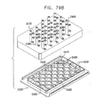
ここで、吸引装置及びピペットを伴った、図21A乃至図22Bの顕微鏡検査前の多重サンプルホルダーの簡略図である、図23A、23B及び23Cを参照する。図23Aを参照すると、参照番号350により指し示された吸引装置が吸引源に導管354を介して連結されたマニホルド352を備えることが示されている。マニホルド352は、均一に間隔を隔てられたニードル356の直線状列と連通するのが好ましい。一対のスペーサー358が、マニホルド352に取り付けられるか、又は、マニホルドと一体成形されている。スペーサー358は、ニードル356の直線状列と一列に並んで配置される。これらのスペーサー358は、頂部要素302の両側にある隣接する位置決め案内部328の中間のところでベース部30の床部320と係合するのが好ましい。スペーサー358は、ニードル356が図1A乃至図10で参照番号110により指し示された電子ビーム透過性で流体不透過性の膜と係合しないことを確実にする。
Reference is now made to FIGS. 23A, 23B and 23C, which are simplified illustrations of the multi-sample holder of FIGS. 21A-22B prior to microscopic examination, with a suction device and pipette. Referring to FIG. 23A, it is shown that a suction device, designated by
図23Aに示されるように、容器支持収容部306は、顕微鏡検査前の多重サンプルホルダー上で互い違いの列に配列されている。かくして、図23Bに示されるように、列毎に、ニードル356のうち3つがアパーチャ324と係合し、ニードル356のうち2つがダミーアパーチャ330と係合し、ニードル356のうち一つが、ダミーアパーチャとして機能するアパーチャ332の一部と係合する。
As shown in FIG. 23A, the container
図23Cは、従来のピペット360を用いて個々のサンプル皿部109に液体を追加した状態を示している。図1A乃至図10で参照番号110により指し示された電子ビーム透過性で流体不透過性の膜とピペットとの意図しない係合を防止するため、カラー要素362が、ピペット360と連係して使用するため設けられてもよい。
FIG. 23C shows a state in which liquid is added to each
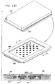
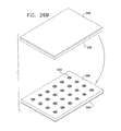
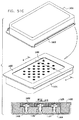
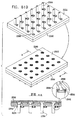
ここで、図1A乃至図10で示された型式のSEM互換性サンプル皿部で使用する、顕微鏡検査用多重サンプルホルダーの簡略図である、図24A、24B及び24Cを参照する。図24Aに示されるように、顕微鏡検査用多重サンプルホルダーは、ベース部400と、密封カバー404とを備えるのが好ましい。ベース部400は、好ましくは、プラスチック材料から射出成形され、容器支持収容部406の列を形成する。各々の容器支持収容部406は、アパーチャ408により形成されるのが好ましい。該アパーチャを通してSEM顕微鏡の検査を実行することができる。図1A乃至図8Cで参照番号100により指し示されたエンクロージャ要素で、各アパーチャ408に隣接して、サンプル皿部425の突起部424を収容するように配列された、一対の互いに整列した対の直立相互間隔突起部410が形成されるのが好ましい。サンプル皿部425は、図3A乃至図5Bに示されたサンプル皿部109と略同一であってもよいが、ねじ込み式機構又は他の取り付け機構を必要としない。
Reference is now made to FIGS. 24A, 24B and 24C, which are simplified illustrations of a multi-sample holder for microscopy used in the SEM compatible sample pan section of the type shown in FIGS. 1A-10. As shown in FIG. 24A, the multiple sample holder for microscopy preferably includes a
ベース部400は、顕微鏡検査前の多重サンプルホルダーの内部で所望レベルの湿度を維持するため使用される液体を保持するようになった、複数の液体リザーバー412を形成してもよい。
The base 400 may form a plurality of
密封カバー404は、サンプル皿部425の各々と個々に密封係合するように配列されている。好ましくは、密封カバー404は、その下側に、図24Cに示されたOリング426が提供される。Oリング426は、密封カバー404が、適所に、好ましくはベース部400との取り外し可能なスナップ式の係合で配置されたとき、サンプル皿部425の各々の頂部リム表面と密封係合するように、そこに密封され配列されている。
The sealing
図24Bは、1つのサンプル皿部425がベース部400の皿支持収容部406に配置された状態の図24Aの装置を示している。図24Cは、ベース部400とスナップ式に係合する密封カバー404を示している。密封カバー404は、これにより、Oリング426と、周囲を取り囲む密封カバー404の一部分とを用いてサンプル皿部425の各々の個々の密封を提供する。
FIG. 24B shows the apparatus of FIG. 24A in a state where one
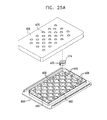
ここで、図11A乃至図20で示された型式のSEM互換性サンプル皿部で使用する、顕微鏡検査用多重サンプルホルダーの簡略図である、図25A、図25B及び図25Cを参照する。図25Aに示されるように、顕微鏡検査用多重サンプルホルダーは、ベース部450と、密封カバー454とを備えるのが好ましい。ベース部450は、好ましくは、プラスチック材料から射出成形され、皿支持収容部456の列を形成する。各々の皿支持収容部456は、アパーチャ458により形成されるのが好ましい。該アパーチャを通してSEM顕微鏡の検査を実行することができる。各アパーチャ458に隣接して、サンプル皿部475の突起部474を収容するように配列された、一対の互いに整列した対の直立相互間隔突起部460が形成されるのが好ましい。サンプル皿部475は、図13A乃至図15Bに示されたサンプル皿部109と略同一であってもよいが、ねじ込み式機構又は他の取り付け機構を必要としない。
Reference is now made to FIGS. 25A, 25B and 25C, which are simplified illustrations of multiple sample holders for microscopy used in the SEM compatible sample pans of the type shown in FIGS. 11A-20. As shown in FIG. 25A, the multiple sample holder for microscopy preferably includes a
ベース部450は、顕微鏡検査用の多重サンプルホルダーの内部で所望レベルの湿度を維持するため使用される液体を保持するようになった、複数の液体リザーバー462を形成してもよい。
The base 450 may form a plurality of
密封カバー454は、図25Cに示される、ダイヤフラム476とサンプル皿部475の各々とを個々に密封係合するため配置される。該ダイヤフラムは、密封カバー454に形成されたアパーチャ478を覆って密封式に取り付けられている。好ましくは、図11A乃至図20を参照して上述されたダイヤフラム218と同一であってもよい、ダイヤフラム476の列が、密封カバー454の下側に設けられている。個々のダイヤフラム476は、密封カバー454が、適所に、好ましくはベース部450との取り外し可能なスナップ式の係合で配置されたとき、サンプル皿部475の各々の頂部リム表面と密封係合するように配列されている。
The sealing
図25Bは、1つのサンプル皿部475がベース部450の皿支持収容部456に配置された状態の図25Aの装置を示している。図25Cは、ベース部450とスナップ式に係合する密封カバー454を示している。密封カバー454は、これにより、ダイヤフラム476を用いてサンプル皿部475の各々の個々の密封を提供する。
FIG. 25B shows the apparatus of FIG. 25A in a state in which one
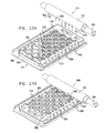
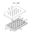
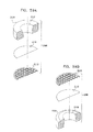
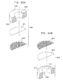
本発明の好ましい実施例に係る、複数のSEM互換性サンプル容器を形成する顕微鏡検査用多重サンプルホルダーの簡略図である、図26A及び図26Bを参照する。図26Aに示されるように、顕微鏡検査用多重サンプルホルダーは、ベース部500と、密封カバー504とを備えるのが好ましい。ベース部500は、好ましくは、プラスチック材料から射出成形され、サンプル容器506の列を形成する。各々のサンプル容器506は、アパーチャ508を備えるのが好ましい。該アパーチャを通してSEM顕微鏡の検査を実行することができる。図26Bに示される電子ビーム透過性で流体不透過性の膜510が各アパーチャ508を覆って密封する。膜510は、図1A乃至図10を参照して上述された膜110と同一であるのが好ましい。密封カバー504は、サンプル容器506の各々と個々に密封係合するように配列されている。
Reference is made to FIGS. 26A and 26B, which are simplified illustrations of a multi-sample holder for microscopy forming a plurality of SEM compatible sample containers, according to a preferred embodiment of the present invention. As shown in FIG. 26A, the multiple sample holder for microscopic examination preferably includes a
図26Bは、図26Aの装置が密封係合した状態を示している。この密封係合により、サンプル容器506の各々の個々の密封が提供される。
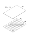
本発明の好ましい実施例に係る、複数のSEM互換性サンプル容器を形成する顕微鏡検査用多重サンプルホルダーの簡略図である、図27A及び図27Bを参照する。図27Aに示されるように、顕微鏡検査用多重サンプルホルダーは、ベース部550と、密封カバー554とを備えるのが好ましい。ベース部550は、好ましくは、プラスチック材料から射出成形され、サンプル容器556の列を形成する。各々のサンプル容器556は、アパーチャ558を備えるのが好ましい。該アパーチャを通してSEM顕微鏡の検査を実行することができる。図27Bに示される電子ビーム透過性で流体不透過性の膜560が各アパーチャ558を覆って密封する。膜560は、図11A乃至図20を参照して上述された膜210と同一であるのが好ましい。密封カバー554は、例えば、約50のショア硬度を有する、0.2〜0.3mmの厚さのシリコンゴム等から成形された弾性シート材料から形成されたダイヤフラムであるのが好ましく、サンプル容器556の各々と個々に密封係合するように配列されている。
FIG. 26B shows the device of FIG. 26A in a sealing engagement. This sealing engagement provides an individual seal for each of the
Reference is made to FIGS. 27A and 27B, which are simplified illustrations of a multiple sample holder for microscopy forming a plurality of SEM compatible sample containers, in accordance with a preferred embodiment of the present invention. As shown in FIG. 27A, the multiple sample holder for microscopy preferably includes a
図27Bは、図27Aの装置が密封係合した状態を示している。この密封係合により、サンプル容器556の各々の個々の密封が提供される。
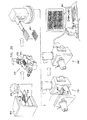
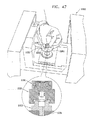
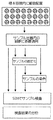
ここで、本発明の好ましい実施例に従って構成され、作動するSEMベースのサンプル検査システムの簡略図である、図28を参照する。図28に示されるように、複数の顕微鏡検査前の多重サンプルホルダー600は、各々が図1A乃至図20に示された型式の多数のSEM互換性サンプル容器602を含み、細菌培養器604内に配置された状態で示されている。好ましくは、関心のあるサンプルを同定するため、参照番号606で示されるように、容器602がホルダー600内に取り付けられた状態で、容器602内のサンプルの光学顕微鏡検査が実行される。好ましくは、倒立光学顕微鏡608がこの目的のため用いられる。
FIG. 27B shows the device of FIG. 27A in sealing engagement. This sealing engagement provides an individual seal for each of the
Reference is now made to FIG. 28, which is a simplified illustration of a SEM-based sample inspection system constructed and operative in accordance with a preferred embodiment of the present invention. As shown in FIG. 28, a plurality of pre-microscopic multiple sample holders 600 each include a number of SEM
好ましくは、図示のような例えばロボットアーム等の自動位置決めシステムが、システムを通して、顕微鏡検査前多重サンプルホルダー600及び容器602を搬送するため使用される。1つ以上のステージで手動介入操作が適宜用いられてもよいことが認められよう。
Preferably, an automatic positioning system, such as a robot arm as shown, is used to transport the pre-microscopic multiple sample holder 600 and
その後、個々の容器602は、ホルダー600から取り外され、取り外し可能な電子顕微鏡標本ステージ610に配置され、次に、走査型電子顕微鏡612内に導入される。その結果得られた画像は、オペレータにより視覚的に検査され、及び/又は、典型的にはコンピュータ614で具現化される従来の画像分析機能により分析される。
Thereafter, the
ここで、本発明の別の好ましい実施例に従って構成され、作動するSEMベースのサンプル検査システムの簡略図である、図29を参照する。図29に示されるように、複数の顕微鏡検査前の多重サンプルホルダー650は、各々が図24A乃至図25Cに示された型式のうちいずれかの多数のSEM互換性サンプル容器652を含み、細菌培養器654内に配置された状態で示されている。好ましくは、関心のあるサンプルを同定するため、参照番号656で示されるように、サンプル皿部がホルダー650内に取り付けられた状態で、皿部652内のサンプルの光学顕微鏡検査が実行される。好ましくは、倒立光学顕微鏡658がこの目的のため用いられる。
Reference is now made to FIG. 29, which is a simplified illustration of an SEM-based sample inspection system constructed and operative in accordance with another preferred embodiment of the present invention. As shown in FIG. 29, a plurality of pre-microscopic
好ましくは、図示のような例えばロボットアーム等の自動位置決めシステムが、システムを通して、サンプル皿部652を含む顕微鏡検査前多重サンプルホルダー650を搬送するため使用される。1つ以上のステージで手動介入操作が適宜用いられてもよいことが認められよう。
Preferably, an automatic positioning system such as a robotic arm as shown is used to transport the pre-microscopic
その後、ホルダー650は、電子顕微鏡標本ステージ660に配置され、次に、走査型電子顕微鏡662内に導入される。その結果得られた画像は、オペレータにより視覚的に検査され、及び/又は、典型的にはコンピュータ664で具現化される従来の画像分析機能により分析される。
Thereafter, the
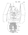
ここで、本発明の更に別の好ましい実施例に従って構成され、作動するSEMベースのサンプル検査システムの簡略図である、図30を参照する。図30に示されるように、複数の顕微鏡検査前の多重サンプルホルダー670は、各々が図26A乃至図27Bのいずれか1つに示された多数のSEM互換性サンプル容器672を形成し、細菌培養器674内に配置された状態で示されている。好ましくは、関心のあるサンプルを同定するため、参照番号676で示されるように、サンプル容器672内のサンプルの光学顕微鏡検査がホルダーの位置で実行される。好ましくは、倒立光学顕微鏡678がこの目的のため用いられる。
Reference is now made to FIG. 30, which is a simplified diagram of an SEM-based sample inspection system constructed and operative in accordance with yet another preferred embodiment of the present invention. As shown in FIG. 30, a plurality of pre-microscopic
好ましくは、図示のような例えばロボットアーム等の自動位置決めシステムが、システムを通して、顕微鏡検査前多重サンプルホルダー670を搬送するため使用される。1つ以上のステージで手動介入操作が適宜用いられてもよいことが認められよう。
Preferably, an automatic positioning system such as a robotic arm as shown is used to transport the pre-microscopic
その後、ホルダー670は、電子顕微鏡標本ステージ680に配置され、次に、走査型電子顕微鏡682内に導入される。その結果得られた画像は、オペレータにより視覚的に検査され、及び/又は、典型的にはコンピュータ684で具現化される従来の画像分析機能により分析される。
Thereafter, the
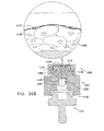
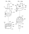
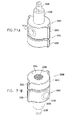
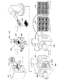
本発明の別の好ましい実施例に従って構成され、作動する、分解された操作型電子顕微鏡(SEM)互換性サンプル容器の、各々反対側に向いた簡略的な分解図である、図31A乃至図35Bを参照する。図31A及び図31Bに示されるように、SEM互換性サンプル容器は、閉鎖の容易さ及び速さを向上させるため配列された、参照番号1100及び1102により指し示された、第1及び第2の互いにねじ込まれるエンクロージャ要素を備えている。エンクロージャ要素1100及び1102は、好ましくは、プラスチックから成形され、導電性金属コーティングで被覆される。
FIGS. 31A-35B are simplified exploded views, each directed to the opposite side, of a disassembled operational electron microscope (SEM) compatible sample container constructed and operative in accordance with another preferred embodiment of the present invention. Refer to As shown in FIGS. 31A and 31B, SEM-compatible sample containers are first and second indicated by
第1のエンクロージャ要素1100は、好ましくは、液体サンプルエンクロージャを形成し、略中央アパーチャ1106を持つベース表面1104を有する。図32A及び図32Bに詳細に示される、電子ビーム透過性で流体不透過性の膜サブアッセンブリ1108は、図33A、33B及び図35A、35Bに示されるように、アパーチャ1106に対向してこれを覆って、エンクロージャ要素1100の内部に着座している。エンクロージャ要素1100内に適切に配置されたサブアッセンブリ1108を備えるサンプル皿部は、図33A乃至図35Bに示されるように、参照番号1109により指し示されている。
The
更に図32A及び図32Bを参照すると、電子ビーム透過性で流体不透過性の膜1110が、接着剤により、機械式支持格子1112に接着される。該膜1110は、アメリカ合衆国、UT、オレムのモックステック社から市販されている、カタログ番号LWN00033等のポリイミド膜を含むのが好ましい。格子1112は、図面で縮尺通りには示されておらず、該格子としては、アメリカ合衆国、ニューヨークのコートランドのバックビーメアズから市販されている、カタログ番号BM0090−01が好ましい。接着剤は、アメリカ合衆国、NJのグランベリーのノーランドプロダクツ社から市販されており、カタログ番号NOA61であるのが好ましい。サンプルエンクロージャ形成リング1114は、好ましくは、例えばアメリカ合衆国、NJのグランベリーのノーランドプロダクツ社から市販されているカタログ番号NOA61の接着剤により、電子ビーム透過性で流体不透過性の膜1110に接着されている。リング1114は、スペイン、バルセロナ市のイルペンから市販されている、例えばカタログ番号692106001000等のPMMA(ポリメチルメタクリレート)から形成されるのが好ましく、約20マイクロリットルの体積で約2mmの高さを備えた液体サンプルエンクロージャを画定するのが好ましい。好ましくは、リング1114は、傾斜壁を有する液体サンプルエンクロージャ1116を画定するように構成される。
Still referring to FIGS. 32A and 32B, an electron beam transmissive and fluid
第1のOリング1118は、第2のエンクロージャ要素1102の内側表面と、接続要素1122との間に配置されているのが好ましい。接続要素1122は、プラスチックから成形され、導電性金属コーティングで被覆されているのが好ましい。第2のOリング1123は、接続要素1122と、サブアッセンブリ1108のリング1114との間に配置されているのが好ましい。Oリング1118及び1123は、エンクロージャ要素1100及び1102と接続要素1122とが緊密なねじ込み係合であるとき、要素1100及び1102のねじ込み係合が密封係合であるべき必要性を無くすように作用する。
The first O-
接続要素1122は、凹部1124を有するのが好ましい。接続要素1122には、図35A及び図35Bに示される、突起部1126が形成され、該突起部は凹部1124内に突出している。
The connecting
ポジショナー1128は、2つの直立した可撓性突起部1130から構成されるのが好ましく、各々は、突起部1130の端部1134に形成されたリッジ1132を備える。ポジショナー1128は、プラスチックから成形されるのが好ましい。図35A及び35Bに示されるように、突起部1130は、接続要素1122の凹部1124内に挿入されたとき互いに押圧し、一旦、リッジ1132が接続要素1122の突起部1126に着座されたならば、直立位置へとスナップ式に戻る。
The
ポジショナー1128は、リム1137から延在する、夫々の径方向に延在する位置決め保持突起部1136が設けられているのが好ましい。位置決め保持突起部1136は、ポジショナー1128の回転を防止するためリング1114のサンプルエンクロージャ1116の傾斜壁に形成されたアパーチャ1140内に着座されている。
The
コイルスプリング1142は、リム1137と、突起部1130のリッジ1132との間にポジショナー1128に配置されている。スプリング1142は、硬化ステンレス鋼から形成されるのが好ましい。
The
ポジショナー1128及びスプリング1142は、エンクロージャ要素1100及び1102と接続要素1122とが密接にねじ込み係合した状態にあるとき、電子ビーム透過性で流体不透過性の膜1110に接触して非液体サンプルを上方に移動させるように作用する。
The
第2のエンクロージャ要素1102には、走査型電子顕微鏡の標本ステージの適切な凹部(図示せず)に着座するように配列された、略中央スタブ1150が形成されるのが好ましい。図31A乃至図40に示される容器は、従来の走査型電子顕微鏡の従来のスタブ用凹部に適合するサイズで働き、それが何であれ、変形する必要はないことが、本発明の特別な特徴である。スタブの様々な形態及びサイズを、様々な走査型電子顕微鏡に適合するように提供することができることが認められよう。
The
エンクロージャ要素1100及び1102は、容器を、適切な多重容器ホルダー内に容易に着座させることを可能にし、更にユーザーがエンクロージャ要素1100及び1102をねじ込み開閉することを援助するため、径方向に延在する夫々の位置決め保持突起部1154及び1155が設けられるのが好ましい。好ましくは、各々のエンクロージャ要素1100及び1102上の突起部1154及び1155の相対的な方位角方向の配置は、図34A及び図34Bに示されるように、これら突起部間の相対的な方位角方向の整列が、要素間のねじ込み閉鎖の所望の度合いを指し示すようになっているのが好ましい。
ここで、図31A乃至図35BのSEM互換性サンプル容器の作動態様を作動の3段階で各々示した3つの断面図である、図36A、36B及び36Cを参照する。図36Aは、エンクロージャ要素1100及び1102と接続要素1122をねじ込み閉鎖する前の図31Bに示される配位で配列されている、組織サンプル1160を蓄えた図31A乃至図35Bの容器を示している。電子ビーム透過性で流体不透過性の膜1110が、図36Aにおいて、略平坦であるように示されている。
Reference is now made to FIGS. 36A, 36B, and 36C, which are three cross-sectional views illustrating the operational aspects of the SEM compatible sample container of FIGS. 31A-35B, respectively, in three stages of operation. FIG. 36A shows the container of FIGS. 31A-35B storing a
図36Bは、周囲からの組織サンプルエンクロージャ1116の密封を生成するエンクロージャ要素1100及び1102と接続要素1122との間の完全なねじ込み係合に続く中間状態にある、図36Aの容器を示している。なお、組織サンプル1160はポジショナー1128により発揮された力に起因して、電子ビーム透過性で流体不透過性の膜1110と緊密に接触している。電子ビーム透過性で流体不透過性の膜1110と、その支持格子1112とが、この態様におけるその密封の結果生じた組織サンプルエンクロージャ1116の圧力形成に起因して、外方にしなっていることが見て取れる。
FIG. 36B shows the container of FIG. 36A in an intermediate state following full threaded engagement between
図36Cは、典型的には、10−2〜10−6ミリバールの真空でSEMの脱ガス環境に配置されたときの図36Bの容器を示している。この環境では、電子ビーム透過性で流体不透過性の膜1110と支持格子1112とが、図36Bの周囲環境に配置されたときよりも、より大きい度合いで外方にしなっていることが見て取れる。更には、電子ビーム透過性で流体不透過性の膜1110は、図36Bの周囲環境で生じたものよりも大きい度合いで格子1112の隙間を通って隙間内に入り込もうとしていることが理解できる。
FIG. 36C shows the container of FIG. 36B when placed in a SEM degassing environment with a vacuum of typically 10 −2 to 10 −6 mbar. In this environment, it can be seen that the electron beam permeable and fluid
ここで、図31A乃至図36CのSEM互換性サンプル容器を使用した、サンプルを含む組織とSEMへの挿入とを示す、簡略図及び断面図である、図37を参照する。
図37は、SEM1166のステージ1164に挿入される、図31Bの配位にある閉鎖容器を示している。容器の配位が図37に示されたものとは反対であるSEMが存在することが認められよう。
Reference is now made to FIG. 37, which is a simplified and cross-sectional view showing the tissue containing the sample and insertion into the SEM using the SEM compatible sample container of FIGS. 31A-36C.
FIG. 37 shows the closed container in the configuration of FIG. 31B inserted into the
ここで、図31A乃至図35BのSEM互換性サンプル容器の様々な作動配位を4つの作動段階で示した、4つの断面図である、図38A、38B、38C及び38Dを参照する。図38Aは、図31A乃至図35Bの容器と同一である容器1170を示し、それ以外では、該容器は、以下で特定されるように、細胞成長プラットフォーム1174上で成長する細胞1172を有するサンプルを含み、エンクロージャ要素1100及び1102と接続要素1122とのねじ込み閉鎖前に、図31Bに示された配位に配列されている。電子ビーム透過性で流体不透過性の膜1110が、略平坦であるように図38Aに示されている。細胞成長プラットフォーム1174は、図31A乃至図37の実施例のポジショナー1128に対応する、適切に構成されたポジショナー1176に取り外し可能に取り付けられている。典型的には、細胞は、プラットフォーム1174がポジショナー1176上に取り付けられていない間にも、細胞成長プラットフォーム1174上で成長する。プロットフォーム1174の取り付けは、典型的には、SEM検査が行われる直前に行われる。
Reference is now made to FIGS. 38A, 38B, 38C and 38D, which are four cross-sectional views illustrating various operational configurations of the SEM compatible sample container of FIGS. 31A-35B in four operational stages. FIG. 38A shows a
図38Bは、周囲からの、参照番号1178により指し示された細胞サンプルエンクロージャの密封を生成するエンクロージャ要素1100及び1102と接続要素1122との間の完全なねじ込み係合に続く中間状態にある、図38Aの容器を示している。なお、細胞1172を含むサンプルはポジショナー1176により発揮された力に起因して、電子ビーム透過性で流体不透過性の膜1110と緊密に接触している。電子ビーム透過性で流体不透過性の膜1110と、その支持格子1112とが、この態様におけるその密封の結果生じた細胞サンプルエンクロージャ1178の圧力形成に起因して、外方にしなっていることが見て取れる。
FIG. 38B is in an intermediate state following full threaded engagement between
図38Cは、典型的には、10−2〜10−6ミリバールの真空でSEMの脱ガス環境に配置されたときの図38Bの容器を示している。この環境では、電子ビーム透過性で流体不透過性の膜1110と支持格子1112とが、図38Bの周囲環境に配置されたときよりも、より大きい度合いで外方にしなっていることが見て取れる。更には、電子ビーム透過性で流体不透過性の膜1110は、図38Bの周囲環境で生じたものよりも大きい度合いで格子1112の隙間を通って隙間内に入り込もうとしていることが理解できる。
FIG. 38C shows the container of FIG. 38B when placed in a SEM degassing environment with a vacuum of typically 10 −2 to 10 −6 mbar. In this environment, it can be seen that the electron beam transmissive and fluid
図38Dは、SEM1166のステージ1164に挿入される、図31Bの配位にある閉鎖容器1170を示している。容器の配位が図38Dに示されたものとは反対であるSEMが存在することが認められよう。
FIG. 38D shows the
ここで、図31A乃至図37のSEM互換性サンプル容器を使用した、サンプルのSEM検査の簡略図及び断面図である、図39を参照する。図39に示されるように、参照番号1180により指し示された容器は、SEMにより発生された電子ビーム1182が電子ビーム透過性で流体不透過性の膜1110を通過し、容器1180内のサンプル1184を含む組織に照射されように、SEM1166のステージ1164上に配置されている。サンプル1184からの後方散乱電子は、電子ビーム透過性で流体不透過性の膜1110を通過し、SEMの一部を形成する検出器1186により検出される。例えば2次電子検出器1188等の1つ以上の追加の検出器を設けてもよい。電子ビーム励起に起因してサンプル1184により放射されるX線放射を検出するためのX線検出器(図示せず)を設けてもよい。
Reference is now made to FIG. 39, which is a simplified and cross-sectional view of a sample SEM inspection using the SEM compatible sample container of FIGS. 31A-37. As shown in FIG. 39, the container designated by
ここで、本発明の好ましい実施例に係る容器1180内のサンプル1184との電子ビーム相互作用の詳細を概略的に示す図40を追加的に参照する。なお、本発明は、図40に示されるように、それらの平均的な原子番号により互いから区別される特徴群の高いコントラストの画像形成を可能にしている。図40では、比較的高い平均原子番号を有する、細胞核1190は、周囲の核質1192よりも電子をより大きく後方散乱させることが示されている。
Reference is now additionally made to FIG. 40, which schematically shows details of electron beam interaction with a
なお、本発明の好ましい実施例によれば、約2ミクロンまでの深さのサンプル内部の画像形成は、図40に示されるように、50KeVより低いエネルギーレベルを有する電子に対して達成可能であり、電子ビーム透過性で流体不透過性の膜1110より下方に位置する細胞核1190が画像形成される。
It should be noted that according to a preferred embodiment of the present invention, imaging within a sample up to about 2 microns deep can be achieved for electrons having an energy level lower than 50 KeV, as shown in FIG. The
ここで、本発明の別の好ましい実施例に従って構成され、作動する、分解された走査型電子顕微鏡(SEM)の互換性サンプル容器の、各々反対側に向いた簡略的な分解図である、図41A乃至図45Bを参照する。図41A及び図41Bに示されるように、SEM互換性サンプル容器は、閉鎖の容易さ及び速さを向上させるように配列された、参照番号1200及び1202により指し示された、第1及び第2の相互にねじ込まれるエンクロージャ要素を備えている。エンクロージャ要素1200及び1202は、プラスチックから成形され、導電性金属コーティングで被覆されるのが好ましい。
Here, a simplified exploded view, each directed to the opposite side, of a disassembled scanning electron microscope (SEM) compatible sample container constructed and operative in accordance with another preferred embodiment of the present invention, FIG. Reference is made to FIGS. 41A to 45B. As shown in FIGS. 41A and 41B, SEM compatible sample containers are first and second indicated by
第1のエンクロージャ要素1200は、好ましくは、サンプルエンクロージャを形成し、略中央アパーチャ1206を持つベース表面1204を有する。図42A及び図42Bに詳細に示される、電子ビーム透過性で流体不透過性の膜サブアッセンブリ1208は、図43A、43B及び図45A、45Bに示されるように、アパーチャ1206に対向してこれを覆って、エンクロージャ要素1200の内部に着座している。エンクロージャ要素1200内に適切に配置されたサブアッセンブリ1208を備えるサンプル皿部は、図43A乃至図45Bに示されるように、参照番号1209により指し示されている。
The
更に図42A及び図42Bを参照すると、電子ビーム透過性で流体不透過性の膜1210が、接着剤により、機械式支持格子1212に接着される。該膜210は、アメリカ合衆国、UT、オレムのモックステック社から市販されている、カタログ番号LWN00033等のポリイミド膜を含むのが好ましい。格子1212は、図面で縮尺通りには示されておらず、該格子としては、アメリカ合衆国、ニューヨークのコートランドのバックビーメアズから市販されている、カタログ番号BM0090−01が好ましい。接着剤は、アメリカ合衆国、NJのグランベリーのノーランドプロダクツ社から市販されており、カタログ番号NOA61であるのが好ましい。サンプルエンクロージャ形成リング1214は、好ましくは、例えばアメリカ合衆国、NJのグランベリーのノーランドプロダクツ社から市販されているカタログ番号NOA61の接着剤により、電子ビーム透過性で流体不透過性の膜1210に接着されている。リング1214は、スペイン、バルセロナ市のイルペンから市販されている、例えばカタログ番号692106001000等のPMMA(ポリメチルメタクリレート)から形成されるのが好ましく、約20マイクロリットルの体積で約2mmの高さを備えた液体サンプルエンクロージャを画定するのが好ましい。好ましくは、リング1214は、傾斜壁を有する液体サンプルエンクロージャ1216を画定するように構成される。
Still referring to FIGS. 42A and 42B, an electron beam permeable, fluid
好ましくは、ダイヤフラム1218が、Oリング部220から一体成形され、該Oリング部220には、伸張可能シート部221が密封されているのがよい。ダイヤフラム1218は、第2のエンクロージャ要素1202の内側表面1219と、接続要素1222との間に配置されるのが好ましい。接続要素1222は、好ましくは、プラスチックから成形され、導電金属コーティングで被覆されている。ダイヤフラム1218は、約50のショア硬度を有するシリコンゴムから成形されるのが好ましく、シート部1221は、0.2〜0.3mmの厚さを有するのが好ましい。
Preferably, the
Oリング1223は、接続要素1222と、サブアッセンブリ1208のリング1214との間に配置されているのが好ましい。ダイヤフラム1218及びOリング1223は、エンクロージャ要素1200及び1202と接続要素1222とが緊密なねじ込み係合にあるとき、要素1200及び1202と接続要素1222とのねじ込み係合が密封係合であるべき必要性を無くすように、並びに、その動的圧力及び静的圧力リリーフを提供するように作動する。
O-
接続要素1222は、中央凹部1224を有するのが好ましい。接続要素1222には、凹部1224内に突出する、図45A及び45Bに示される突起部1226が形成されている。
The connecting
ポジショナー1228が、2つの直立した可撓性突起部1230から構成されるのが好ましく、各々は、突起部1230の端部1234に形成されたリッジ1232を備える。ポジショナー1228は、プラスチックから成形されるのが好ましい。図45A及び45Bに示されるように、突起部1230は、接続要素1222の凹部1224内に挿入されたとき互いに押圧し、一旦、リッジ1232が接続要素1222の突起部1226に着座されたならば、直立位置へとスナップ式に戻る。
The
ポジショナー1228は、リム1237から延在する、夫々の径方向に延在する位置決め保持突起部1236が設けられているのが好ましい。位置決め保持突起部1236は、ポジショナー1228の回転を防止するためリング1214のサンプルエンクロージャ1216の傾斜壁に形成されたアパーチャ1240内に着座されている。
The
コイルスプリング1242は、リム1237と、突起部1230のリッジ1232との間でポジショナー1228上に配置されている。スプリング1242は、硬化ステンレス鋼から形成されるのが好ましい。
The
ポジショナー1228及びスプリング1242は、エンクロージャ要素1200及び1202と、接続要素1222とが密接にねじ込み係合した状態にあるとき、電子ビーム透過性で流体不透過性の膜1210に接触して非液体サンプルを上方に移動させるように作用する。
第2のエンクロージャ要素1202には、走査型電子顕微鏡の標本ステージの適切な凹部(図示せず)に着座するように配列された、貫通ボア1252を有する略中央スタブ1250が形成されるのが好ましい。ボア1252は、ダイヤフラム1218の一方の側と(SEM)互換性サンプル容器が配置されている環境との間に流体連通チャンネルを形成することにより、ダイヤフラム1218が圧力リリーフを提供することを可能にする。図41A乃至図50に示される容器は、従来の走査型電子顕微鏡の従来のスタブ用凹部に適合するサイズで働き、それが何であれ、変形する必要はないことが、本発明の特別な特徴である。スタブの様々な形態及びサイズを、様々な走査型電子顕微鏡に適合するように提供することができることが認められよう。
The
エンクロージャ要素1200及び1202は、容器を、適切な多重容器ホルダー内に容易に着座させることを可能にし、更にユーザーがエンクロージャ要素1200及び1202をねじ込み開閉することを援助するため、径方向に延在する夫々の位置決め保持突起部1254及び1255が設けられるのが好ましい。好ましくは、各々のエンクロージャ要素1200及び1202上の突起部1254及び1255の相対的な方位角方向の配置は、図44A及び図44Bに示されるように、これら突起部間の相対的な方位角方向の整列が、要素間のねじ込み閉鎖の所望の度合いを指し示すようになっているのが好ましい。
図41A乃至図45BのSEM互換性サンプル容器の作動態様を作動の3段階で各々示した3つの断面図である、図46A、46B及び46Cを参照する。図46Aは、エンクロージャ要素1200及び1202と接続要素1222とをねじ込み閉鎖する前に、図41Bに示された配位で配列されている、組織サンプル1260を蓄えた図41A乃至図45Bの容器を示している。電子ビーム透過性で流体不透過性の膜1210が、図46Aにおいて、略平坦であるように示されている。
Reference is made to FIGS. 46A, 46B, and 46C, which are three cross-sectional views each illustrating the operational aspects of the SEM compatible sample container of FIGS. 41A-45B in three stages of operation. FIG. 46A shows the container of FIGS. 41A-45B
図46Bは、周囲からの組織サンプルエンクロージャ1216の密封を生成するエンクロージャ要素1200及び1202の間の完全なねじ込み係合に続く中間状態にある、図46Aの容器を示している。なお、組織サンプル1260は、ポジショナー1228により発揮された力に起因して、電子ビーム透過性で流体不透過性の膜1210と緊密に接触した状態にある。ダイヤフラム1218は、この態様におけるその密封の結果生じた組織サンプルエンクロージャ1216の圧力形成に起因して、外方にしなっていることが見て取れる。本実施例では、電子ビーム透過性で流体不透過性の膜1210及びその支持格子1212も、この態様におけるその密封の結果生じた組織サンプルエンクロージャ1216の圧力形成に起因して、外方にしなっているが、ダイヤフラム1218の作用に起因して、かなりより小さい程度にしか、しなっていない。これは、図46Bと図36Bとを比較することにより、理解することができる。
FIG. 46B shows the container of FIG. 46A in an intermediate state following a complete screwed engagement between
図46Cは、典型的には、10−2〜10−6ミリバールの真空でSEMの脱ガス環境に配置されたときの図46Bの容器を示している。この環境では、ダイヤフラム1218が、図46Bの周囲環境のときよりもより大きい度合いで外方にしなり、電子ビーム透過性で流体不透過性の膜1210と支持格子1212とが、図46Bの周囲環境に配置されたときよりも、より大きい度合いで外方にしなっているが、ダイヤフラム1218の作用に起因して、図36Cの実施例のときよりも、かなり小さい度合いでしかしなっていないことが見て取れる。これは、図46Cと図36Cとを比較することにより、理解することができる。
FIG. 46C shows the container of FIG. 46B when placed in a SEM degassing environment with a vacuum of typically 10 −2 to 10 −6 mbar. In this environment, the
なお、電子ビーム透過性で流体不透過性の膜1210は、図46Bの周囲環境で生じたものよりも大きい度合いで格子1212の隙間を通って隙間内に入り込もうとしているが、ダイヤフラム1218の作用に起因して、図36Cの実施例のときよりもかなり小さい度合いでしかしなっていないことが理解できる。これは、図46Cと図36Cとを比較することにより、理解することができる。
Note that the electron beam permeable and fluid
ここで、図41A乃至図46CのSEM互換性サンプル容器を使用した、サンプルを含む組織とSEMへの挿入とを示す、簡略図及び断面図である、図47を参照する。
図47は、SEM1266のステージ1264に挿入される、図41Bの配位にある閉鎖容器を示している。容器の配位が図47に示されたものとは反対であるSEMが存在することが認められよう。
Reference is now made to FIG. 47, which is a simplified and cross-sectional view showing the tissue containing the sample and insertion into the SEM using the SEM compatible sample container of FIGS. 41A-46C.
FIG. 47 shows the closed container in the configuration of FIG. 41B inserted into the
ここで、図41A乃至図45BのSEM互換性サンプル容器の様々な作動配位を4つの作動段階で示した、4つの断面図である、図48A、48B、48C及び48Dを参照する。図48Aは、図41A乃至図45Bの容器と同一である容器1270を示し、それ以外では、該容器は、以下で特定されるように、細胞成長プラットフォーム1274上で成長する細胞1272を有するサンプルを含み、エンクロージャ要素1200及び1202と接続要素1222とのねじ込み閉鎖前に、図41Bに示された配位に配列されている。電子ビーム透過性で流体不透過性の膜1210が、略平坦であるように図48Aに示されている。細胞成長プラットフォーム1274は、図41A乃至図47の実施例のポジショナー1228に対応する、適切に構成されたポジショナー1276に取り外し可能に取り付けられている。典型的には、細胞は、プラットフォーム1274がポジショナー1276上に取り付けられていない間にも、細胞成長プラットフォーム1274上で成長する。プロットフォーム1274の取り付けは、典型的には、SEM検査が行われる直前に行われる。
Reference is now made to FIGS. 48A, 48B, 48C and 48D, which are four cross-sectional views illustrating various operational configurations of the SEM compatible sample container of FIGS. 41A-45B in four operational stages. FIG. 48A shows a
図48Bは、周囲からの、参照番号1278により指し示された細胞サンプルエンクロージャの密封を生成するエンクロージャ要素1200及び1202と接続要素1222との間の完全なねじ込み係合に続く中間状態にある、図48Aの容器を示している。なお、細胞1272を含むサンプルはポジショナー1276により発揮された力に起因して、電子ビーム透過性で流体不透過性の膜1210と緊密に接触している。電子ビーム透過性で流体不透過性の膜1210と、その支持格子1212とが、この態様におけるその密封の結果生じた細胞サンプルエンクロージャ1278の圧力形成に起因して、外方にしなっているが、ダイヤフラム1218の作用に起因して、図38Bの実施例のときよりもかなり小さい度合いでしかしなっていないことが見て取れる。これは、図48Bと図38Bとを比較することにより、理解することができる。
FIG. 48B is in an intermediate state following full threaded engagement between
図48Cは、典型的には、10−2〜10−6ミリバールの真空でSEMの脱ガス環境に配置されたときの図48Bの容器を示している。この環境では、電子ビーム透過性で流体不透過性の膜1210と支持格子1212とが、図48Bの周囲環境に配置されたときよりも、より大きい度合いで外方にしなっていることが見て取れる。更には、電子ビーム透過性で流体不透過性の膜1210は、図48Bの周囲環境で生じたものよりも大きい度合いで格子1212の隙間を通って隙間内に入り込もうとしているが、ダイヤフラム1218の作用に起因して、図38Cの実施例のときよりもかなり小さい度合いでしかしなっていないことが見て取れる。これは、図48Cと図38Cとを比較することにより、理解することができる。
FIG. 48C shows the container of FIG. 48B when placed in a SEM degassing environment with a vacuum of typically 10 −2 to 10 −6 mbar. In this environment, it can be seen that the electron beam transmissive and fluid
図48Dは、SEM1266のステージ1264に挿入される、図41Bの配位にある閉鎖容器1270を示している。容器の配位が図48Dに示されたものとは反対であるSEMが存在することが認められよう。
FIG. 48D shows the
ここで、図41A乃至図47のSEM互換性サンプル容器を使用した、サンプルのSEM検査の簡略図及び断面図である、図49を参照する。図49に示されるように、参照番号1280により指し示された容器は、SEMにより発生された電子ビーム1282が電子ビーム透過性で流体不透過性の膜1210を通過し、容器1280内のサンプル1284を含む組織に照射されように、SEM1266のステージ1264上に配置されている。サンプル1284からの後方散乱電子は、電子ビーム透過性で流体不透過性の膜1210を通過し、SEMの一部を形成する検出器1286により検出される。例えば2次電子検出器1288等の1つ以上の追加の検出器を設けてもよい。電子ビーム励起に起因してサンプル1284により放射されるX線放射を検出するためのX線検出器(図示せず)を設けてもよい。
Reference is now made to FIG. 49, which is a simplified and cross-sectional view of an SEM inspection of a sample using the SEM compatible sample containers of FIGS. 41A-47. As shown in FIG. 49, the container designated by
ここで、本発明の好ましい実施例に係る容器1280内のサンプル1284との電子ビーム相互作用の詳細を概略的に示す図50を追加的に参照する。なお、本発明は、図50に示されるように、それらの平均的な原子番号により互いから区別される特徴群の高いコントラストの画像形成を可能にしている。図50では、比較的高い平均原子番号を有する、細胞核1290は、周囲の核質1292よりも電子をより大きく後方散乱させることが示されている。
Reference is now additionally made to FIG. 50, which schematically shows details of electron beam interaction with a
なお、本発明の好ましい実施例によれば、約2ミクロンまでの深さのサンプル内部の画像形成は、図50に示されるように、50KeVより低いエネルギーレベルを有する電子に対して達成可能であり、電子ビーム透過性で流体不透過性の膜1210より下方に位置する細胞核1290が画像形成される。
It should be noted that according to a preferred embodiment of the present invention, imaging within a sample up to about 2 microns deep can be achieved for electrons having an energy level below 50 KeV, as shown in FIG. The
ここで、図31A乃至図40で示された型式のSEM互換性サンプル皿部で使用する、顕微鏡検査用多重サンプルホルダーの簡略図である、図51A、51B及び51Cを参照する。図51Aに示されるように、顕微鏡検査用多重サンプルホルダーは、ベース部1400と、密封カバー1404とを備えるのが好ましい。ベース部1400は、好ましくは、プラスチック材料から射出成形され、容器支持収容部1406の列を形成する。各々の容器支持収容部1406は、アパーチャ1408により形成されるのが好ましい。該アパーチャを通してSEM顕微鏡の検査を実行することができる。各アパーチャ1408に隣接して、サンプル皿部1425の突起部1424を収容するように配列された、一対の互いに整列した対の直立相互間隔突起部1410が形成されるのが好ましい。サンプル皿部1425は、図33A乃至図35Bに示されたサンプル皿部1109と略同一であってもよいが、ねじ込み式機構又は他の取り付け機構を必要としない。
Reference is now made to FIGS. 51A, 51B and 51C, which are simplified illustrations of multiple sample holders for microscopy used in the SEM compatible sample pans of the type shown in FIGS. 31A-40. As shown in FIG. 51A, the multiple sample holder for microscopy preferably includes a
密封カバー1404は、サンプル皿部1425の各々と個々に密封係合するように配列されている。好ましくは、密封カバー1404は、その下側に、図51Cに示されたOリング1426が提供される。Oリング1426は、密封カバー1404が、適所に、好ましくはベース部1400との取り外し可能なスナップ式の係合で配置されたとき、サンプル皿部1425の各々の頂部リム表面と密封係合するように、そこに密封され配列されている。
The sealing
好ましくは、密封カバー1404は、その下側で、図51Cに示された、突起部1428の列が設けられ、サンプル皿部1425に着座された電子ビーム透過性で流体不透過性の膜1110(図31A乃至図40に示された)と接触し、その上方に非液体サンプルを移動させるように配列されている。個々のポジショナー1428は、図51Cに示されるように、コイル1430内に吊り下げられている。
Preferably, the sealing
図51Bは、1つのサンプル皿部1425がベース部1400の皿支持収容部1406に配置された状態の図51Aの装置を示している。図51Cは、ベース部1400とスナップ式に係合する密封カバー1404を示している。密封カバー1404は、これにより、Oリング1426と、周囲を取り囲む密封カバー1404の一部分とを用いてサンプル皿部1425の各々の個々の密封を提供する。
FIG. 51B shows the apparatus of FIG. 51A in a state in which one
ここで、図41A乃至図50で示された型式のSEM互換性サンプル皿部で使用する、顕微鏡検査用多重サンプルホルダーの簡略図である、図52A、52B及び52Cを参照する。図52Aに示されるように、顕微鏡検査用多重サンプルホルダーは、ベース部1450と、密封カバー1454とを備えるのが好ましい。ベース部1450は、好ましくは、プラスチック材料から射出成形され、皿部支持収容部1456の列を形成する。各々の皿部支持収容部1456は、アパーチャ1458により形成されるのが好ましい。該アパーチャを通してSEM顕微鏡の検査を実行することができる。各アパーチャ1458に隣接して、サンプル皿部1475の突起部1474を収容するように配列された、一対の互いに整列した対の直立相互間隔突起部1460が形成されるのが好ましい。サンプル皿部1475は、図43A乃至図45Bに示されたサンプル皿部1209と略同一であってもよいが、ねじ込み式機構又は他の取り付け機構を必要としない。
Reference is now made to FIGS. 52A, 52B and 52C, which are simplified illustrations of multiple sample holders for microscopy used in the SEM compatible sample pans of the type shown in FIGS. 41A-50. As shown in FIG. 52A, the multiple sample holder for microscopy preferably includes a
好ましくは、密封カバー1454は、その下側に、図52Cに示されたOリング1476が提供される。Oリング1476は、密封カバー1454が、適所に、好ましくはベース部1450との取り外し可能なスナップ式の係合で配置されたとき、サンプル皿部1475の各々の頂部リム表面と密封係合するように、そこに密封され配列されている。
Preferably, the sealing
密封カバー1454は、図52Cに示されるダイヤフラム1477を備えた、サンプル皿部1475の各々の個々の密封係合のため配列されている。該ダイヤフラムは、密封カバー1454に形成されたアパーチャ1478を覆って密封式に取り付けられている。好ましくは、図41A乃至図50を参照して上述されたダイヤフラム1218と同一であってもよい、ダイヤフラム1477の列が、密封カバー1454の下側に設けられている。個々のダイヤフラム1477は、密封カバー1454が、適所に、好ましくはベース部1450との取り外し可能なスナップ式の係合で配置されたとき、サンプル皿部1475の各々の頂部リム表面と密封係合するように配列されている。
The sealing
好ましくは、密封カバー1454には、ポジショナー1480の列が設けられている。個々のポジショナー1480は、サンプル皿部1475に着座された電子ビーム透過性で流体不透過性の膜1210(図41A乃至図50に示された)と接触し、その上方に非液体サンプルを移動させるように配列されている。個々のポジショナー1428は、図51Cに示されるように、コイル1432内に吊り下げられている。
Preferably, the sealing
図52Bは、1つのサンプル皿部1475がベース部1450の皿支持収容部1456に配置された状態の図52Aの装置を示している。図52Cは、ベース部1450とスナップ式に係合する密封カバー1454を示している。密封カバー1454は、これにより、ダイヤフラム1476を用いて、サンプル皿部1475の各々の個々の密封を提供する。
FIG. 52B shows the apparatus of FIG. 52A with one
ここで、本発明の好ましい実施例に係る、複数のSEM互換性サンプル容器を形成する顕微鏡検査用多重サンプルホルダーの簡略図である、図53A及び53Bを参照する。図53Aに示されるように、顕微鏡検査用多重サンプルホルダーは、ベース部1500と、密封カバー1504とを備えるのが好ましい。ベース部1500は、好ましくは、プラスチック材料から射出成形され、サンプル容器1506の列を形成する。各々のサンプル容器1506は、アパーチャ1508を備えるのが好ましい。該アパーチャを通してSEM顕微鏡の検査を実行することができる。図53Bに示された、電子ビーム透過性で流体不透過性の膜1510が、各アパーチャ1508を覆って密封されている。膜1510は、図31A乃至図40を参照して上述された膜1110と同一であるのが好ましい。密封カバー1504は、サンプル容器1506の各々と個々に密封係合するように配列されている。
Reference is now made to FIGS. 53A and 53B, which are simplified illustrations of a multiple sample holder for microscopy forming a plurality of SEM compatible sample containers, according to a preferred embodiment of the present invention. As shown in FIG. 53A, the multiple sample holder for microscopy preferably includes a
好ましくは、密封カバー1504には、図53Bに示されるポジショナー1520の列が設けられている。個々のポジショナー1520は、図53Bに示されるように、電子ビーム透過性で流体不透過性の膜1510と接触し、その上方に非液体サンプルを移動させるように、コイル1522内に吊り下げられている。
Preferably, the sealing
図53Bは、1つのサンプル皿部1475がベース部1450の皿支持収容部1456に配置された状態の図52Aの装置を示している。図52Cは、ベース部1450とスナップ式に係合する密封カバー1454を示している。密封カバー1454は、これにより、ダイヤフラム1476を用いて、サンプル皿部1475の各々の個々の密封を提供する。
FIG. 53B shows the apparatus of FIG. 52A with one
ここで、本発明の好ましい実施例に係る、複数のSEM互換性サンプル容器を形成する顕微鏡検査用多重サンプルホルダーの簡略図である、図53A及び53Bを参照する。図53Aに示されるように、顕微鏡検査用多重サンプルホルダーは、ベース部1500と、密封カバー1504とを備えるのが好ましい。ベース部1500は、好ましくは、プラスチック材料から射出成形され、サンプル容器1506の列を形成する。各々のサンプル容器1506は、アパーチャ1508を備えるのが好ましい。該アパーチャを通してSEM顕微鏡の検査を実行することができる。図53Bに示された、電子ビーム透過性で流体不透過性の膜1510が、各アパーチャ1508を覆って密封されている。膜1510は、図31A乃至図40を参照して上述された膜1110と同一であるのが好ましい。密封カバー1504は、サンプル容器1506の各々と個々に密封係合するように配列されている。
Reference is now made to FIGS. 53A and 53B, which are simplified illustrations of a multiple sample holder for microscopy forming a plurality of SEM compatible sample containers, according to a preferred embodiment of the present invention. As shown in FIG. 53A, the multiple sample holder for microscopy preferably includes a
図53Bは、図53Aの装置が密封係合した状態を示している。この密封係合により、サンプル容器1506の各々の個々の密封が提供される。
ここで、本発明の好ましい実施例に係る、複数のSEM互換性サンプル容器を形成する顕微鏡検査用多重サンプルホルダーの簡略図である、図54A及び図54Bを参照する。図54Aに示されるように、顕微鏡検査用多重サンプルホルダーは、ベース部1550と、密封カバー1554とを備えるのが好ましい。ベース部1550は、好ましくは、プラスチック材料から射出成形され、サンプル容器1556の列を形成する。各々のサンプル容器1556は、アパーチャ1558を備えるのが好ましい。該アパーチャを通してSEM顕微鏡の検査を実行することができる。
FIG. 53B shows the device of FIG. 53A in a sealing engagement. This sealing engagement provides an individual seal for each of the
Reference is now made to FIGS. 54A and 54B, which are simplified illustrations of a multiple sample holder for microscopy forming a plurality of SEM compatible sample containers, according to a preferred embodiment of the present invention. As shown in FIG. 54A, the multiple sample holder for microscopic examination preferably includes a
図54Bに示される電子ビーム透過性で流体不透過性の膜1560が各アパーチャ1558を覆って密封する。膜1560は、図41A乃至図50を参照して上述された膜1210と同一であるのが好ましい。密封カバー1554は、例えば、約50のショア硬度を有する、0.2〜0.3mmの厚さのシリコンゴム等から成形された弾性シート材料から形成されたダイヤフラム1562であるのが好ましい。ダイヤフラム1562は、密封カバー1554に形成されたアパーチャ1564を覆って密封式に取り付けられ、サンプル容器1556の各々と個々に密封係合するように配列されている。
An electron beam transmissive and fluid
好ましくは、密封カバー1554には、図54Bに示されたポジショナー1570の列が設けられている。個々のポジショナー1570は、図54Bに示されるように、電子ビーム透過性で流体不透過性の膜1560と接触し、その上方に非液体サンプルを移動させるように、コイル1572内に吊り下げられている。
Preferably, the sealing
図54Bは、図54Aの装置が密封係合した状態を示している。この密封係合により、サンプル容器1556の各々の個々の密封が提供される。
ここで、本発明の好ましい実施例に従って構成され、作動するSEMベースのサンプル検査システムの簡略図である、図55を参照する。図55に示されるように、好ましくは、図示のような例えばロボットアーム等の自動位置決めシステムが、システムを通して、多数のSEM互換性サンプル容器1602を搬送するため使用される。1つ以上のステージで手動介入操作が適宜用いられてもよいことが認められよう。
FIG. 54B shows the device of FIG. 54A in sealing engagement. This sealing engagement provides an individual seal for each of the
Reference is now made to FIG. 55, which is a simplified illustration of a SEM-based sample inspection system constructed and operative in accordance with a preferred embodiment of the present invention. As shown in FIG. 55, an automatic positioning system such as, for example, a robot arm as shown is preferably used to transport a number of SEM
その後、個々の容器1602は、電子顕微鏡標本ステージ1610に配置され、次に、走査型電子顕微鏡1612内に導入される。その結果得られた画像は、オペレータにより視覚的に検査され、及び/又は、典型的にはコンピュータ1614で具現化される従来の画像分析機能により分析される。
Thereafter, the
ここで、本発明の更に別の好ましい実施例に従って構成され、作動するSEMベースのサンプル検査システムの簡略図である、図56を参照する。図56に示されるように、複数の顕微鏡検査用の多重サンプルホルダー1650は、各々が図51A乃至図52Cに示された型式のいずれかの多数のSEM互換性サンプル皿部1652を形成し、テーブル1654に載った状態で示されている。好ましくは、関心のあるサンプルを同定するため、参照番号1656で示されるように、サンプル皿部1652内のサンプルの光学顕微鏡検査がサンプル皿部がホルダー1650に取り付けられている間に実行される。好ましくは、解剖顕微鏡1658がこの目的のため用いられる。
Reference is now made to FIG. 56, which is a simplified illustration of an SEM-based sample inspection system constructed and operative in accordance with yet another preferred embodiment of the present invention. As shown in FIG. 56, a plurality of
好ましくは、図示のような例えばロボットアーム等の自動位置決めシステムが、システムを通して、顕微鏡検査用多重サンプルホルダー1650を搬送するため使用される。1つ以上のステージで手動介入操作が適宜用いられてもよいことが認められよう。
Preferably, an automatic positioning system, such as a robotic arm as shown, is used to transport the
その後、ホルダー1650は、電子顕微鏡標本ステージ1660に配置され、次に、走査型電子顕微鏡1662内に導入される。その結果得られた画像は、オペレータにより視覚的に検査され、及び/又は、典型的にはコンピュータ1664で具現化される従来の画像分析機能により分析される。
Thereafter, the
ここで、本発明の更に別の好ましい実施例に従って構成され、作動するSEMベースのサンプル検査システムの簡略図である、図57を参照する。図57に示されるように、複数の顕微鏡検査用の多重サンプルホルダー1670は、図53A乃至図54Bのいずれかに示されるように、各々が多数のSEM互換性サンプル皿部1672を形成し、テーブル1674に載った状態で示されている。好ましくは、関心のあるサンプルを同定するため、参照番号1676で示されるように、サンプル容器1672内のサンプルの光学顕微鏡検査がホルダーの位置で実行される。好ましくは、解剖顕微鏡1678がこの目的のため用いられる。
Reference is now made to FIG. 57, which is a simplified illustration of an SEM-based sample inspection system constructed and operative in accordance with yet another preferred embodiment of the present invention. As shown in FIG. 57, a plurality of microscope
好ましくは、図示のような例えばロボットアーム等の自動位置決めシステムが、システムを通して、顕微鏡検査用多重サンプルホルダー1670を搬送するため使用される。1つ以上のステージで手動介入操作が適宜用いられてもよいことが認められよう。
Preferably, an automatic positioning system, such as a robotic arm as shown, is used to transport the
その後、ホルダー1670は、電子顕微鏡標本ステージ1680に配置され、次に、走査型電子顕微鏡1682内に導入される。その結果得られた画像は、オペレータにより視覚的に検査され、及び/又は、典型的にはコンピュータ1684で具現化される従来の画像分析機能により分析される。
Thereafter, the
ここで、本発明の好ましい実施例に従って構成され、作動する、分解された操作型電子顕微鏡(SEM)互換性サンプル容器の、各々反対側に向いた簡略的な分解図である、図58A乃至図62Bを参照する。図58A及び図58Bに示されるように、SEM互換性サンプル容器は、閉鎖の容易さ及び速さを向上させるため配列された、参照番号2100及び2102により指し示された、第1及び第2の互いにねじ込まれるエンクロージャ要素を備えている。エンクロージャ要素2100及び2102は、好ましくは、プラスチックから成形され、導電性金属コーティングで被覆される。
58A-58 are simplified exploded views, each directed to the opposite side, of a disassembled operational electron microscope (SEM) compatible sample container constructed and operative in accordance with a preferred embodiment of the present invention. Refer to 62B. As shown in FIGS. 58A and 58B, the SEM-compatible sample containers are first and second indicated by
第1のエンクロージャ要素2100は、好ましくは、液体サンプルエンクロージャを形成し、略中央アパーチャ2106を持つベース表面2104を有する。図59A及び図59Bに詳細に示される、電子ビーム透過性で流体不透過性の膜サブアッセンブリ2108は、図60A、60B及び図62A、62Bに示されるように、アパーチャ2106に対向してこれを覆って、エンクロージャ要素2100の内部に着座している。エンクロージャ要素2100内に適切に配置されたサブアッセンブリ2108を備えるサンプル皿部は、図60A乃至図62Bに示されるように、参照番号2109により指し示されている。
The
更に図59A及び図59Bを参照すると、電子ビーム透過性で流体不透過性の膜2110が、接着剤により、機械式支持格子2112に接着される。該膜2110は、アメリカ合衆国、UT、オレムのモックステック社から市販されている、カタログ番号LWN00033等のポリイミド膜であるのが好ましい。格子2112は、図面で縮尺通りには示されておらず、該格子としては、アメリカ合衆国、ニューヨークのコートランドのバックビーメアズから市販されている、カタログ番号BM0090−01が好ましい。接着剤は、アメリカ合衆国、NJのグランベリーのノーランドプロダクツ社から市販されており、カタログ番号NOA61であるのが好ましい。液体サンプルエンクロージャ形成リング2114は、好ましくは、例えばアメリカ合衆国、NJのグランベリーのノーランドプロダクツ社から市販されているカタログ番号NOA61の接着剤により、電子ビーム透過性で流体不透過性の膜2110に接着されている。リング2114は、スペイン、バルセロナ市のイルペンから市販されている、例えばカタログ番号692106001000等のPMMA(ポリメチルメタクリレート)から形成されるのが好ましく、約20マイクロリットルの体積で約2mmの高さを備えた液体サンプルエンクロージャを画定するのが好ましい。好ましくは、リング2114は、傾斜壁を有する液体サンプルエンクロージャ2116を画定するように構成される。
Still referring to FIGS. 59A and 59B, an electron beam transmissive and fluid
Oリング2118は、リング2114と、第2のエンクロージャ要素2102の内部表面2120との間に配置されているのが好ましい。Oリング2118は、エンクロージャ要素2100及び2102が緊密なねじ込み係合であるとき、要素2100及び2102のねじ込み係合が密封係合であるべき必要性を無くすように作用する。
The O-
第2のエンクロージャ要素2102には、走査型電子顕微鏡の標本ステージの適切な凹部(図示せず)に着座するように配列された、貫通ボア2123を有する略中央スタブ2122が形成されるのが好ましい。
The
エンクロージャ要素2100及び2102は、容器を、適切な多重容器ホルダー内に容易に着座させることを可能にし、更にユーザーがエンクロージャ要素2100及び2102をねじ込み開閉することを援助することを可能にする。好ましくは、各々のエンクロージャ要素2100及び2102上の突起部2124及び2125の相対的な方位角方向の配置は、図61A及び図61Bに示されるように、これら突起部間の相対的な方位角方向の整列が、要素間のねじ込み閉鎖の所望の度合いを指し示すようになっているのが好ましい。
SEM検査の間に電子ビーム透過性で流体不透過性の膜2110に面していないサンプル側から、液体サンプルエンクロージャ2116内のサンプルからの光を受け取るように、光案内部2126が設けられている。
A
光案内部2126は、切頭錐体先端部2128を備えたシリンダーから形成され、スタブ2122のボア2123内に挿入される。光案内部2126は、好ましくは、アメリカ合衆国、CT、ポムフレットの12ファイバーRdのファイバーオプティックステクノロジー社から市販されている、数値アパーチャ0.66の、プラスチック若しくはガラス製のクラッドを用いた光案内部であり、接着剤等の任意の従来手段により、エンクロージャ2102に密封されている。
The
錐体先端部2128の壁は所定角度をなして構成され、該所定角度は、サンプルから放射された入射光子が光案内部2126内で反射されることを確実にするように、臨界反射角より小さくされている。
The wall of the
ここで、図53A乃至図62BのSEM互換性サンプル容器の作動態様を作動の3段階で各々示した3つの断面図である、図63A、63B及び63Cを参照する。図63Aは、エンクロージャ要素2100及び2102をねじ込み閉鎖する前の図58Bに示される配位で配列されている、液体サンプル2130を蓄えた図58A乃至図62Bの容器を示している。なお、液体サンプルは、表面張力に起因して、液体サンプルエンクロージャ2116からは流れ出ない。電子ビーム透過性で流体不透過性の膜2110が、図63Aにおいて、略平坦であるように示されている。
Reference is now made to FIGS. 63A, 63B, and 63C, which are three cross-sectional views illustrating the operation of the SEM compatible sample container of FIGS. 53A-62B, respectively, in three stages of operation. FIG. 63A shows the container of FIGS. 58A-62B storing a
図63Bは、周囲からの液体サンプルエンクロージャ2116の密封を生成するエンクロージャ要素2100及び2102の間の完全なねじ込み係合に続く中間状態にある、図63Aの容器を示している。光案内先端部2128は、液体サンプル2130内に浸漬された状態で示されている。電子ビーム透過性で流体不透過性の膜2110と、その支持格子2112とが、この態様におけるその密封の結果生じた液体サンプルエンクロージャ2116の圧力形成に起因して、外方にしなっていることが見て取れる。
FIG. 63B shows the container of FIG. 63A in an intermediate state following full threaded engagement between
図63Cは、典型的には、10−2〜10−6ミリバールの真空でSEMの脱ガス環境に配置されたときの図6Bの容器を示している。この環境では、電子ビーム透過性で流体不透過性の膜2110と支持格子2112とが、図63Bの周囲環境に配置されたときよりも、より大きい度合いで外方にしなっていることが見て取れる。更には、電子ビーム透過性で流体不透過性の膜2110は、図63Bの周囲環境で生じたものよりも大きい度合いで格子2112の隙間を通って隙間内に入り込もうとしていることが理解できる。
FIG. 63C shows the container of FIG. 6B when placed in a SEM degassing environment with a vacuum of typically 10 −2 to 10 −6 mbar. In this environment, it can be seen that the electron beam transmissive and fluid
ここで、図58A乃至図63CのSEM互換性サンプル容器を使用した、細胞成長、液体除去、液体追加、密封及びSEMへの挿入の各状態の簡略断面図である、図64A、64B、64C、64D及び64Eを参照する。典型的な細胞培養状況を示す、図64Aを参照すると、サブアッセンブリ2108を内部に配置させたエンクロージャ要素2100は、図58Aに示された配置態様にあり、液体媒体2142内の細胞2140は液体サンプルエンクロージャ2116内に配置され、これらの細胞2140が、電子ビーム透過性で流体不透過性の膜2110に接触して横たわっている。
Here, FIGS. 64A, 64B, 64C are simplified cross-sectional views of cell growth, liquid removal, liquid addition, sealing, and insertion into the SEM using the SEM compatible sample containers of FIGS. 58A-63C. Reference is made to 64D and 64E. Referring to FIG. 64A illustrating a typical cell culture situation, the
図64Bは、典型的には吸引によって液体サンプルエンクロージャ2116から液体を除去した状態を示し、図64Cは、液体サンプルエンクロージャ2116に液体を追加した状態を示している。液体の除去及び追加を多数回に亘って液体サンプルエンクロージャ2116内のサンプルに関して実行してもよい。好ましくは、液体除去及び追加のため用いられる装置は、電子ビーム透過性で流体不透過性の膜2110の意図しない破裂を防止するように、設計され、備え付けられるのがよい。
FIG. 64B shows a state where liquid is removed from the
図64Dは、図64Cに示される細胞2140を液体媒体2142内に含む容器の閉鎖状態を示している。光案内先端部2128が、液体サンプル2140の液体媒体2142内に浸漬されている状態で示されている。図64Eは、SEM2146のステージ2144上に挿入される閉鎖容器を図58Bの配位で示している。容器の配位が図64Eに示されたものとは反対であるSEMが存在することが認められよう。
FIG. 64D shows the closed state of the container containing the
図64A乃至図64Dは、液体サンプルエンクロージャ2116に関する液体の追加又は除去に拘わらず、サンプルを含む液体の少なくとも一部分が電子ビーム透過性で流体不透過性の膜2110と接触したままとなる状況を例示している。この状況は、電子ビーム透過性で流体不透過性の膜2110に、サンプルの一部が吸収され、そうでなければ、接着される状況を含んでいてもよい。サンプルを含む液体の例は、細胞、培養菌、血液、バクテリア及び無細胞材料を含んでいてもよい。
FIGS. 64A-64D illustrate a situation in which at least a portion of the liquid containing the sample remains in contact with the electron beam transmissive and fluid
ここで、図58A乃至図63CのSEM互換性サンプル容器を使用した、電子ビーム透過性で流体不透過性の膜2110と接触したサンプル含有液体、密封及びSEMへの挿入の各状態の簡略断面図である、図65A、65B及び65Cを参照する。図65A乃至図65Cは、サンプルを含む液体2160の少なくとも一部分が電子ビーム透過性で流体不透過性の膜2110と接触しているが、それに接着されていない状況を例示している。サンプルを含む液体の例には、例えば、ミルク、化粧用クリーム、ペイント、インク、及び、液体形態の薬剤等、様々な乳濁液及び懸濁液がある。図65及び図65Bで、サブアッセンブリ2108を内部に配置させた、エンクロージャ要素2100は、図58Aに示される配位にあることが見て取れよう。
Here, using the SEM compatible sample container of FIGS. 58A-63C, a simplified cross-sectional view of each of the sample-containing liquid in contact with the electron beam permeable fluid
図65Bは、サンプル2160を含む容器の閉鎖状態を示している。図65Cは、SEM2146のステージ2144上に挿入された、図58Bの配位にある、閉鎖容器を示している。容器の配位が図65Cに示されたものとは反対であるSEMが存在することが認められよう。
FIG. 65B shows the closed state of the container containing the
ここで、図58A乃至図63CのSEM互換性サンプル容器を使用した、サンプルの光検出を用いたSEM検査の簡略図及び断面図である、図66を参照する。図66に示されるように、参照番号2170により指し示された容器は、SEM2146のステージ2144で凹部2171に配置された状態で示されている。ステージ2144は、SEM検査の間、サンプル2174を含む液体内の関心のある領域を検査するため、電子ビーム2172の下方に容器2170を配置することを可能にするように、回転動作する。
Reference is now made to FIG. 66, which is a simplified and cross-sectional view of SEM inspection using photodetection of a sample using the SEM compatible sample container of FIGS. 58A-63C. As shown in FIG. 66, the container pointed to by
SEMにより発生された電子ビーム2172は、電子ビーム透過性で流体不透過性の膜2110を通過し、容器2170内のサンプル2174を含む液体に照射される。サンプル2174からの後方散乱電子は、電子ビーム透過性で流体不透過性の膜2110を通過し、SEMの一部を形成する検出器2176により検出される。例えば2次電子検出器2178等の1つ以上の追加の検出器を設けてもよい。電子ビーム励起に起因してサンプル2174により放射されるX線放射を検出するためのX線検出器(図示せず)を設けてもよい。
The
電子ビーム励起に起因して液体サンプル2174から放射される光子2180は、図58A乃至図63Cの光案内部2126と同じである、参照番号2184により指し示された第1の光案内部を通って、第2の光案内部2186へと伝達される。第2の光案内部2186は、光子2180を、例えば光増幅管(PMT)2188等の光検出器へと伝達するように作動する。光検出器2188から得られた光強度の時間依存測定は、走査電子ビームの位置に関する情報と組み合わされ、当該技術分野で知られた方法によりサンプル2174の画像を生成するように、好ましくは、コンピュータ2189上のデジタル画像として、結合される。
好ましくは、第2の光案内部2186は、屈折に起因した光案内部2184及び2186の間の通路内の光子の損失を最小にし、2つの光案内部の相対的整列をずらすように、第1の光案内部2184の断面領域の直径よりも大きい直径を備えた断面領域を有する。
Preferably, the second light guide 2186 minimizes the loss of photons in the path between the light guides 2184 and 2186 due to refraction, and shifts the relative alignment of the two light guides. Each
図示の実施例では、第2の光案内部2186は、好ましくはL字形状湾曲部内に形成されるのが好ましく、第2の光案内部2186の長さを通して光子2180の内部反射を確実にする角度でL字形状の光案内部2186に沿って配置された、多数の光ファイバーを備えるのが好ましい。
In the illustrated embodiment, the second light guide 2186 is preferably formed within an L-shaped bend, ensuring internal reflection of the
本発明では、光子2180は、第1の光案内部2184から、第2の光案内部2186を介して、SEM2146の床部の下方に配置された光検出器まで垂直下方に伝達され得ることが認められよう。代替例として、光子2180は、第1の光案内部2184から光検出器まで伝達されてもよく、第2の光案内部2186を省略してもよい。
In the present invention, the
本発明の別の実施例では、光子2180は、フィルター、回折格子又はプリズム(図示せず)等の従来手段により、光検出器2188による検出前に、スペクトル分析されてもよい。これは、1つ以上の特定の範囲内にある波長の光子の検出を可能にし、サンプル2174の組成及び構造又はサンプル2174内部の特徴に関する追加の情報をもたらす。
In another embodiment of the invention,
加えて、例えば、光案内部2184及び2186の屈折率に類似した屈折率のオイル若しくはゲル(図示せず)等の液体は、光子2180が光案内部2184及び2186の外部に散乱することを防止するため、光案内部2184及び2186の間に配置されてもよい。
In addition, for example, liquids such as oil or gel (not shown) having a refractive index similar to that of the
ここで、本発明の好ましい実施例に係る容器2170内のサンプル2174との電子ビーム相互作用の詳細を概略的に示す図67を追加的に参照する。なお、本発明は、図67に示されるように、それらの平均的な原子番号により、又は、電子の励起に起因したそれらの平均的な発光収量により、互いから区別される特徴群の高いコントラストの画像形成を可能にしている。図67では、比較的高い平均原子番号を有する、細胞核2190は、周囲の核質2192よりも電子をより大きく後方散乱させることが示されている。
Reference is now additionally made to FIG. 67, which schematically shows details of electron beam interaction with a
光子2180は、細胞核2190から放射され、光案内部2184を介して、光検出器2188(図66に示される)へと伝達される。なお、後方散乱電子の検出器により得られたコントラスト、及び、光子検出により得られたコントラストは、異なる物理的プロセスに起因し、サンプル内部の特徴の化学的特性に起因しており、従って、一般には重なり合わない。
The
なお、本発明の好ましい実施例によれば、約2ミクロンまでの深さのサンプル内部の画像形成は、図67に示されるように、50KeVより低いエネルギーレベルを有する電子に対して達成可能であり、電子ビーム透過性で流体不透過性の膜2110より下方に位置する細胞核2190が画像形成される。
It should be noted that according to a preferred embodiment of the present invention, imaging inside a sample up to about 2 microns deep can be achieved for electrons having energy levels below 50 KeV, as shown in FIG. The
ここで、本発明の別の好ましい実施例に従って構成され、作動する、分解された走査型電子顕微鏡(SEM)互換性サンプル容器の、各々反対側に向いた簡略的な分解図である、図68A乃至図72Bを参照する。図68A及び図68Bに示されるように、SEM互換性サンプル容器は、閉鎖の容易さ及び速さを向上させるため配列された、参照番号2200及び2202により指し示された、第1及び第2の互いにねじ込まれるエンクロージャ要素を備えている。エンクロージャ要素2200及び2202は、好ましくは、プラスチックから成形され、導電性金属コーティングで被覆される。
68A is a simplified exploded view, each directed to the opposite side, of an exploded scanning electron microscope (SEM) compatible sample container constructed and operative in accordance with another preferred embodiment of the present invention. Reference is made to FIG. 72B. As shown in FIGS. 68A and 68B, the SEM compatible sample containers are first and second indicated by
第1のエンクロージャ要素2200は、好ましくは、液体サンプルエンクロージャを形成し、略中央アパーチャ2206を持つベース表面2204を有する。図69A及び図69Bに詳細に示される、電子ビーム透過性で流体不透過性の膜サブアッセンブリ2208は、図70A、70B及び図72A、72Bに示されるように、アパーチャ2206に対向してこれを覆って、エンクロージャ要素2200の内部に着座している。エンクロージャ要素2200内に適切に配置されたサブアッセンブリ2208を備えるサンプル皿部は、図70A乃至図72Bに示されるように、参照番号2209により指し示されている。
The
更に図69A及び図69Bを参照すると、電子ビーム透過性で流体不透過性の膜2210が、接着剤により、機械式支持格子2212に接着されている状態が示されている。該膜2210は、アメリカ合衆国、UT、オレムのモックステック社から市販されている、カタログ番号LWN00033等のポリイミド膜を含むのが好ましい。格子2212は、図面で縮尺通りには示されておらず、該格子は、アメリカ合衆国、ニューヨークのコートランドのバックビーメアズから市販されている、カタログ番号BM0090−01であるのが好ましい。接着剤は、アメリカ合衆国、NJのグランベリーのノーランドプロダクツ社から市販されているカタログ番号NOA61であるのが好ましい。液体サンプルエンクロージャ形成リング2214は、好ましくは、例えばアメリカ合衆国、NJのグランベリーのノーランドプロダクツ社から市販されているカタログ番号NOA61の接着剤により、電子ビーム透過性で流体不透過性の膜2210に接着されている。リング2214は、スペイン、バルセロナ市のイルペンから市販されている、例えばカタログ番号692106001000等のPMMA(ポリメチルメタクリレート)から形成されるのが好ましく、約20マイクロリットルの体積で約2mmの高さを備えた液体サンプルエンクロージャを画定するのが好ましい。好ましくは、リング2214は、傾斜壁を有する液体サンプルエンクロージャ2216を画定するように構成される。
Still referring to FIGS. 69A and 69B, an electron beam transmissive and fluid
好ましくは、ダイヤフラム2218が提供され、動的及び静的な圧力リリーフを提供するように作動する。好ましくは、ダイヤフラム2218は、Oリング部2220から一体成形され、該Oリング部2220には、伸張可能シート部2221が密封されている。ダイヤフラム2218は、約50のショア硬度を有するシリコンゴムから成形されるのが好ましく、シート部2221は、0.2〜0.3mmの厚さを有するのが好ましい。
Preferably, a
ダイヤフラム2218は、第2のエンクロージャ要素2202の壁の外側表面に形成された第1のアパーチャ2222内に挿入される。図72A及び図72Bに示される第2のアパーチャ2223は、第2のエンクロージャ要素2202の壁の内側表面に形成される。第1のアパーチャ2222及び第2のアパーチャ2223は、ダイヤフラム2218が、ダイヤフラム2218の一方の側部とSEM互換性サンプル容器が配置されている環境との間に流体連通チャンネルを形成することにより圧力リリーフを提供することを可能にする。アパーチャ2222内にダイヤフラム2218を保持するためプラグ2224が設けられるのが好ましい。プラグ2224は、好ましくは、略中央アパーチャ226を有するリング2225から形成され、例えば緊密な適合等の任意の従来手段により、アパーチャ2222により形成された第2のエンクロージャ要素2202の内側表面に取り付けられている。
Oリング2228は、リング2214と、第2のエンクロージャ要素2202の内部表面2230との間に配置されているのが好ましい。Oリング2228は、エンクロージャ要素2200及び2202が緊密なねじ込み係合であるとき、要素2200及び2202のねじ込み係合が密封係合であるべき必要性を無くすように作用する。
The O-
第2のエンクロージャ要素2202には、走査型電子顕微鏡の標本ステージの適切な凹部(図示せず)に着座するように配列された、貫通ボア2233を有する略中央スタブ2232が形成されるのが好ましい。
The
エンクロージャ要素2200及び2202は、容器を、適切な多重容器ホルダー内に容易に着座させることを可能にし、更にユーザーがエンクロージャ要素2200及び2202をねじ込み開閉することを援助するため、径方向に延在する夫々の位置決め保持突起部2234及び2235が設けられるのが好ましい。好ましくは、各々のエンクロージャ要素2200及び2202上の突起部2234及び2235の相対的な方位角方向の配置は、図71A及び図71Bに示されるように、これら突起部間の相対的な方位角方向の整列が、要素間のねじ込み閉鎖の所望の度合いを指し示すようになっているのが好ましい。
SEM検査の間に電子ビーム透過性で流体不透過性の膜2210に面していないサンプル側から、液体サンプルエンクロージャ2216内のサンプルからの光を受け取るように、光案内部2236が設けられている。
A
光案内部2236は、切頭錐体先端部2238を備えたシリンダーから形成され、スタブ2232のボア2233内に挿入される。光案内部2236は、好ましくは、アメリカ合衆国、CT、ポムフレットの12ファイバーRdのファイバーオプティックステクノロジー社から市販されている、数値アパーチャ0.66の、プラスチック若しくはガラス製のクラッドを用いた光案内部であり、接着剤等の任意の従来手段により、エンクロージャ2202に密封されている。
The
錐体先端部2238の壁は所定角度をなして構成され、該所定角度は、サンプルから放射された入射光子が光案内部2236内で反射されることを確実にするように、臨界反射角より小さくされている。
The wall of the
ここで、図68A乃至図72BのSEM互換性サンプル容器の作動態様を作動の3段階で各々示した3つの断面図である、図73A、73B及び73Cを参照する。図73Aは、エンクロージャ要素2200及び2202をねじ込み閉鎖する前に、図68Bに示された配位で配列されている、液体サンプル2239を蓄えた図68A乃至図72Bの容器を示している。なお、液体サンプルは、表面張力に起因して、液体サンプルエンクロージャ2216からは流れ出ない。電子ビーム透過性で流体不透過性の膜2210が、図73Aにおいて、略平坦であるように示されている。
Reference is now made to FIGS. 73A, 73B, and 73C, which are three cross-sectional views illustrating the operating mode of the SEM compatible sample container of FIGS. FIG. 73A shows the container of FIGS. 68A-72B storing the
図73Bは、周囲からの液体サンプルエンクロージャ2216の密封を生成するエンクロージャ要素2200及び2202の間の完全なねじ込み係合に続く中間状態にある、図73Aの容器を示している。ダイヤフラム2218が、この態様におけるその密封の結果生じた液体サンプルエンクロージャ2216の圧力形成に起因して、外方にしなっていることが見て取れる。本実施例では、電子ビーム透過性で流体不透過性の膜2210及びその支持格子2212も、この態様におけるその密封の結果生じた液体サンプルエンクロージャ2216の圧力形成に起因して、外方にしなっているが、ダイヤフラム2218の作用に起因して、図63Bの実施例のときよりも、かなりより小さい程度にしか、しなっていない。これは、図73Bと図63Bとを比較することにより、理解することができる。
FIG. 73B shows the container of FIG. 73A in an intermediate state following a full threaded engagement between
図73Cは、典型的には、10−2〜10−6ミリバールの真空でSEMの脱ガス環境に配置されたときの図73Bの容器を示している。この環境では、
ダイヤフラム2218が、図73Bの周囲環境のときよりもより大きい度合いで外方にしなり、電子ビーム透過性で流体不透過性の膜2210と支持格子2212とが、図73Bの周囲環境に配置されたときよりも、より大きい度合いで外方にしなっているが、ダイヤフラム2218の作用に起因して、図63Cの実施例のときよりも、かなり小さい度合いでしかしなっていないことが見て取れる。これは、図73Cと図63Cとを比較することにより、理解することができる。
FIG. 73C shows the container of FIG. 73B when placed in a SEM degassing environment with a vacuum of typically 10 −2 to 10 −6 mbar. In this environment,
なお、電子ビーム透過性で流体不透過性の膜2210は、図73Bの周囲環境で生じたものよりも大きい度合いで格子2212の隙間を通って隙間内に入り込もうとしているが、ダイヤフラム2218の作用に起因して、図63Cの実施例のときよりもかなり小さい度合いでしかしなっていないことが理解できる。これは、図73Cと図63Cとを比較することにより、理解することができる。
It should be noted that the electron beam transmissive and fluid
ここで、図68A乃至図73CのSEM互換性サンプル容器を使用した、細胞成長、液体除去、液体追加、密封及びSEMへの挿入の各状態の簡略断面図である、図74A、74B、74C、74D及び74Eを参照する。図64Aと同一で、典型的な細胞の培養状況を示す、図74Aを参照すると、サブアッセンブリ2208を内部に配置させたエンクロージャ要素2200が、図68Aに示される配位にあり、液体媒体2242中の細胞2240が、液体サンプルエンクロージャ2216内に配置され、細胞2240が、電子ビーム透過性で流体不透過性の膜2210に接触して横たわっていることが示されている。
Here, FIGS. 74A, 74B, and 74C are simplified cross-sectional views of cell growth, liquid removal, liquid addition, sealing, and insertion into the SEM using the SEM compatible sample containers of FIGS. 68A-73C. Reference is made to 74D and 74E. Referring to FIG. 74A, which is identical to FIG. 64A and shows a typical cell culture situation, the
図64Bと同一の図74Bは、典型的には吸引により、液体サンプルエンクロージャ2216からの液体の除去を示し、図64Cと同一の図74Cは、液体サンプルエンクロージャ2216への液体の追加を示している。液体の除去及び追加を多数回に亘って液体サンプルエンクロージャ2216内のサンプルに関して実行してもよい。好ましくは、液体除去及び追加のため用いられる装置は、電子ビーム透過性で流体不透過性の膜2210の意図しない破裂を防止するように、設計され、備え付けられるのがよい。
FIG. 74B, identical to FIG. 64B, shows the removal of liquid from the
図74Dは、図74Cに示される細胞2240を液体媒体2242内に含む容器の閉鎖状態を示している。光案内先端部2238が液体サンプルの液体媒体2242内に浸漬されている状態で示されている。図74Eは、SEM2246のステージ2244上に挿入される閉鎖容器を図68Bの配位で示している。容器の配位が図74Eに示されたものとは反対であるSEMが存在することが認められよう。
FIG. 74D shows the closed state of the container containing the
図74A乃至図74Dは、液体サンプルエンクロージャ2216に関する液体の追加又は除去に拘わらず、サンプルを含む液体の少なくとも一部分が電子ビーム透過性で流体不透過性の膜2210と接触したままとなる状況を例示している。この状況は、電子ビーム透過性で流体不透過性の膜2210に、サンプルの一部が吸収され、そうでなければ、接着される状況を含んでいてもよい。サンプルを含む液体の例は、細胞、培養菌、血液、バクテリア及び無細胞材料を含んでいてもよい。
74A-74D illustrate a situation where at least a portion of the liquid containing the sample remains in contact with the electron beam transmissive and fluid
図68A乃至図73CのSEM互換性サンプル容器を使用した、電子ビーム透過性で流体不透過性の膜2110と接触したサンプル含有液体、密封及びSEMへの挿入の各状態の簡略断面図である、図75A、75B及び75Cを参照する。図75A乃至図75Cは、サンプルを含む液体2260の少なくとも一部分が電子ビーム透過性で流体不透過性の膜2210と接触しているが、それに接着されていない状況を例示している。サンプルを含む液体の例には、例えば、ミルク、化粧用クリーム、ペイント、インク、及び、液体形態の薬剤等、様々な乳濁液及び懸濁液がある。図75及び図75Bで、サブアッセンブリ2208を内部に配置させた、エンクロージャ要素2200は、図68Aに示される配位にあることが見て取れよう。図75Aは図65Aと同一である。
FIG. 74 is a simplified cross-sectional view of a sample-containing liquid in contact with an electron beam permeable fluid
図75Bは、サンプル2260を含む容器の閉鎖状態を示している。図75Cは、SEM2246のステージ2244上に挿入された、図68Bの配位にある、閉鎖容器を示している。容器の配位が図75Cに示されたものとは反対であるSEMが存在することが認められよう。
FIG. 75B shows the closed state of the container containing the
ここで、図68A乃至図73CのSEM互換性サンプル容器を使用した、サンプルの光検出を用いたSEM検査の簡略図及び断面図である、図76を参照する。図76に示されるように、参照番号2270により指し示された容器は、SEM2246のステージ2244上で凹部2271に配置された状態で示されている。ステージ2244は、SEM検査の間、サンプル2274を含む液体内の関心のある領域を検査するため、電子ビーム2272の下方に容器2270を配置することを可能にするように、回転動作する。
Reference is now made to FIG. 76, which is a simplified and cross-sectional view of SEM inspection using sample light detection using the SEM compatible sample containers of FIGS. 68A-73C. As shown in FIG. 76, the container pointed to by
SEMにより発生された電子ビーム2272は、電子ビーム透過性で流体不透過性の膜2210を通過し、容器2270内のサンプル2274を含む液体に照射される。サンプル2274からの後方散乱電子は、電子ビーム透過性で流体不透過性の膜2210を通過し、SEMの一部を形成する検出器2276により検出される。例えば2次電子検出器2278等の1つ以上の追加の検出器を設けてもよい。電子ビーム励起に起因してサンプル2274により放射されるX線放射を検出するためのX線検出器(図示せず)を設けてもよい。
The
電子ビーム励起に起因して液体サンプル2274から放射される光子2280は、図68A乃至図73Cの光案内部2226と同じである、参照番号2284により指し示された第1の光案内部を通って、第2の光案内部2286へと伝達される。第2の光案内部2286は、光子2280を、例えば光増幅管(PMT)2188等の光検出器へと伝達するように作動する。この光増倍管には、日本国、静岡県、浜松市砂山町325−6の浜松フォトニクスで市販されているカタログ番号H6180−01等がある。光検出器2288から得られた光強度の時間依存測定は、走査電子ビームの位置に関する情報と組み合わされ、当該技術分野で知られた方法によりサンプル2274の画像を生成するように、好ましくは、コンピュータ2289上のデジタル画像として、結合される。
好ましくは、第2の光案内部2286は、屈折に起因した光案内部2284及び2286の間の通路内の光子の損失を最小にし、2つの光案内部の相対的整列をずらすように、第1の光案内部2284の断面領域の直径よりも大きい直径を備えた断面領域を有する。
Preferably, the
図示の実施例では、第2の光案内部2286は、好ましくはL字形状湾曲部内に形成されるのが好ましく、第2の光案内部2286の長さを通して光子2280の内部反射を確実にする角度でL字形状の光案内部2286に沿って配置された、多数の光ファイバーを備えるのが好ましい。
In the illustrated embodiment, the
本発明では、光子2280は、第1の光案内部2284から、第2の光案内部2286を介して、SEM2246の床部の下方に配置された光検出器まで垂直下方に伝達され得ることが認められよう。代替例として、光子2280は、第1の光案内部2284から光検出器まで伝達されてもよく、第2の光案内部2286を省略してもよい。
In the present invention, the
本発明の別の実施例では、光子2280は、フィルター、回折格子又はプリズム(図示せず)等の従来手段により、光検出器2288による検出前に、スペクトル分析されてもよい。これは、1つ以上の特定の範囲内にある波長の光子の検出を可能にし、サンプル2274の組成及び構造又はサンプル2274内部の特徴に関する追加の情報をもたらす。
In another embodiment of the invention,
加えて、例えば、光案内部2284及び2286の屈折率に類似した屈折率のオイル若しくはゲル(図示せず)等の液体は、光子2280が光案内部2284及び2286の外部に散乱することを防止するため、光案内部2284及び2286の間に配置されてもよい。
In addition, liquids such as oil or gel (not shown) having a refractive index similar to that of the light guides 2284 and 2286, for example, prevent the
ここで、本発明の好ましい実施例に係る容器2270内のサンプル2274との電子ビーム相互作用の詳細を概略的に示す図77を追加的に参照する。なお、本発明は、図77に示されるように、それらの平均的な原子番号により、又は、電子の励起に起因したそれらの平均的な発光収量により、互いから区別される特徴群の高いコントラストの画像形成を可能にしている。図77では、比較的高い平均原子番号を有する、細胞核2290は、周囲の核質2292よりも電子をより大きく後方散乱させることが示されている。
Reference is now additionally made to FIG. 77, which schematically shows details of electron beam interaction with the
光子2280は、図示のように、細胞核2290から放射され、光案内部2284を介して、光検出器2288(図76に示される)へと伝達される。なお、後方散乱電子の検出器により得られたコントラスト、及び、光子検出により得られたコントラストは、異なる物理的プロセスに起因し、サンプル内部の特徴の化学的特性に起因しており、従って、一般には重なり合わない。
As shown, the
なお、本発明の好ましい実施例によれば、約2ミクロンまでの深さのサンプル内部の画像形成は、図77に示されるように、50KeVより低いエネルギーレベルを有する電子に対して達成可能であり、電子ビーム透過性で流体不透過性の膜2210より下方に位置する細胞核2290が画像形成される。
Note that according to a preferred embodiment of the present invention, imaging inside a sample up to about 2 microns deep can be achieved for electrons having an energy level lower than 50 KeV, as shown in FIG. The
図21A乃至図22Bで上記示された顕微鏡検査前の多重サンプルホルダーが、図58A乃至図77に示された型式のSEM互換性サンプル容器で使用するため設けられてもよいことが認められよう。加えて、顕微鏡検査前の多重サンプルホルダーは、図23A、23B及び23Cで上記のように示された吸引装置及びピペットと連係されてもよい。 It will be appreciated that the pre-microscopic multiple sample holder shown above in FIGS. 21A-22B may be provided for use with the type of SEM compatible sample container shown in FIGS. 58A-77. In addition, the multiple sample holder prior to microscopy may be associated with the suction device and pipette shown as above in FIGS. 23A, 23B and 23C.
ここで、図58A乃至図67で示された型式のSEM互換性サンプル皿部で使用する、顕微鏡検査用多重サンプルホルダーの簡略図である、図78A、78B及び78Cを参照する。図78Aに示されるように、顕微鏡検査用多重サンプルホルダーは、ベース部2400と、密封カバー2404とを備えるのが好ましい。ベース部2400は、好ましくは、プラスチック材料から射出成形され、皿部支持収容部2406の列を形成する。各々の皿部支持収容部2406は、アパーチャ2408により形成されるのが好ましい。該アパーチャを通してSEM顕微鏡の検査を実行することができる。各アパーチャ2408に隣接して、サンプル皿部2425の突起部2424を収容するように配列された、一対の互いに整列した対の直立相互間隔突起部2410が形成されるのが好ましい。サンプル皿部2425は、図60A乃至図62Bに示されたサンプル皿部2109と略同一であってもよいが、ねじ込み式機構又は他の取り付け機構を必要としない。
Reference is now made to FIGS. 78A, 78B and 78C, which are simplified illustrations of a multi-sample holder for microscopy used in the SEM compatible sample pan of the type shown in FIGS. 58A-67. As shown in FIG. 78A, the multiple sample holder for microscopy preferably includes a
ベース部2400は、顕微鏡検査用の多重サンプルホルダーの内部で所望レベルの湿度を維持するため使用される液体を保持するようになった、複数の液体リザーバー2412を形成するのが好ましい。
密封カバー2404は、サンプル皿部2425の各々と個々に密封係合するように配列されている。好ましくは、密封カバー2404は、その下側に、図78Cに示されたOリング2426の列が提供される。Oリング2426は、密封カバー2404が、適所に、好ましくはベース部2400との取り外し可能なスナップ式の係合で配置されたとき、サンプル皿部2425の各々の頂部リム表面と密封係合するように、そこに密封され配列されている。
The sealing
密封カバー2404は、光検出の間に、サンプル皿部2425内のサンプルから光を受け取るように配列された光案内部2430の列が設けられているのが好ましい。光案内部2430は、密封カバー2404上に形成されたアパーチャ2432内に挿入される。
The sealing
図78Bは、1つのサンプル皿部2425がベース部2400の皿支持収容部2406に配置された状態の図78Aの装置を示している。図78Cは、ベース部2400とスナップ式に係合する密封カバー2404を示している。密封カバー2404は、これにより、Oリング2426と、周囲を取り囲む密封カバー2404の一部分とを用いてサンプル皿部2425の各々の個々の密封を提供する。
FIG. 78B shows the apparatus of FIG. 78A in a state in which one
ここで、図68A乃至図77で示された型式のSEM互換性サンプル皿部で使用する、顕微鏡検査用多重サンプルホルダーの簡略図である、図79A、図79B及び図79Cを参照する。図79Aに示されるように、顕微鏡検査用多重サンプルホルダーは、ベース部2450と、密封カバー2454とを備えるのが好ましい。ベース部2450は、好ましくは、プラスチック材料から射出成形され、皿支持収容部2456の列を形成する。各々の皿支持収容部2456は、アパーチャ2458により形成されるのが好ましい。該アパーチャを通してSEM顕微鏡の検査を実行することができる。各アパーチャ2458に隣接して、サンプル皿部2475の突起部2474を収容するように配列された、一対の互いに整列した対の直立相互間隔突起部2460が形成されるのが好ましい。サンプル皿部2475は、図70A乃至図72Bに示されたサンプル皿部2209と略同一であってもよいが、ねじ込み式機構又は他の取り付け機構を必要としない。
Reference is now made to FIGS. 79A, 79B and 79C, which are simplified illustrations of a multiple sample holder for microscopy, used in the SEM compatible sample pan of the type shown in FIGS. 68A-77. As shown in FIG. 79A, the multiple sample holder for microscopy preferably includes a
ベース部2450は、顕微鏡検査用の多重サンプルホルダーの内部で所望レベルの湿度を維持するため使用される液体を保持するようになった、複数の液体リザーバー2462を形成してもよい。
密封カバー2454は、サンプル皿部2475の各々と個々に密封係合するように配列されている。好ましくは、密封カバー2454は、その下側に、図78Cに示されたOリング2476の列が提供される。Oリング2476は、密封カバー2454が、適所に、好ましくはベース部2450との取り外し可能なスナップ式の係合で配置されたとき、サンプル皿部2475の各々の頂部リム表面と密封係合するように、そこに密封され配列されている。
The sealing
密封カバー2454には、図68A乃至図77を参照して上述されたダイヤフラム2218と同一であり得る、図79Cに示された、ダイヤフラム2477の列が設けられている。個々のダイヤフラム2477は、密封カバー2454内に形成されたアパーチャ2479に亘って取り付けられたリング2478に着座されている。
好ましくは、密封カバー2454は、光検出の間に、サンプル皿部2475のサンプルから光を受け取るように配列された光案内部2480の列が設けられているのが好ましい。光案内部2480は、密封カバー2454上に形成されたアパーチャ2482内に挿入される。個々の光案内部2480は、SEM検査の間に、サンプル皿部2475内のサンプルから光を収集するため設けられている。
Preferably, the sealing
図79Bは、1つのサンプル皿部2475がベース部2450の皿支持収容部2456に配置された状態の図79Aの装置を示している。図79Cは、ベース部2450とスナップ式に係合する密封カバー2454を示している。密封カバー2454は、これにより、Oリング2476を用いてサンプル皿部2425の各々の個々の密封を提供する。
FIG. 79B shows the apparatus of FIG. 79A in a state where one
ここで、本発明の好ましい実施例に係る、複数のSEM互換性サンプル容器を形成する顕微鏡検査用多重サンプルホルダーの簡略図である、図80A及び図80Bを参照する。図80Aに示されるように、顕微鏡検査用多重サンプルホルダーは、ベース部2500と、密封カバー2504とを備えるのが好ましい。ベース部2500は、好ましくは、プラスチック材料から射出成形され、サンプル容器2506の列を形成する。各々のサンプル容器2506は、アパーチャ2508を備えるのが好ましい。該アパーチャを通してSEM顕微鏡の検査を実行することができる。図80Bに示される電子ビーム透過性で流体不透過性の膜2510が各アパーチャ2508を覆って密封する。膜2510は、図58A乃至図67を参照して上述された膜2110と同一であるのが好ましい。密封カバー2504は、サンプル容器2506の各々と個々に密封係合するように配列されている。
Reference is now made to FIGS. 80A and 80B, which are simplified illustrations of a multiple sample holder for microscopy forming a plurality of SEM compatible sample containers, according to a preferred embodiment of the present invention. As shown in FIG. 80A, the multiple sample holder for microscopy preferably includes a
密封カバー2504は、光検出の間に、サンプル皿部2425内のサンプルから光を受け取るように配列された光案内部2514の列が設けられているのが好ましい。個々の光案内部2514は、密封カバー2504上に形成されたアパーチャ2516内に挿入される。
The sealing
図80Bは、図80Aの装置が密封係合した状態を示している。この密封係合により、サンプル容器2506の各々の個々の密封が提供される。
ここで、本発明の好ましい実施例に係る、複数のSEM互換性サンプル容器を形成する顕微鏡検査用多重サンプルホルダーの簡略図である、図81A及び図81Bを参照する。図81Aに示されるように、顕微鏡検査用多重サンプルホルダーは、ベース部2550と、密封カバー2554とを備えるのが好ましい。ベース部2550は、好ましくは、プラスチック材料から射出成形され、サンプル容器2556の列を形成する。各々のサンプル容器2556は、アパーチャ2558を備えるのが好ましい。該アパーチャを通してSEM顕微鏡の検査を実行することができる。
FIG. 80B shows the device of FIG. 80A in sealing engagement. This sealing engagement provides an individual seal for each of the
Reference is now made to FIGS. 81A and 81B, which are simplified illustrations of a multiple sample holder for microscopy forming a plurality of SEM compatible sample containers, according to a preferred embodiment of the present invention. As shown in FIG. 81A, the multiple sample holder for microscopy preferably includes a
図81Bに示された電子ビーム透過性で流体不透過性の膜2560が各アパーチャ2558を覆って密封する。膜2560は、図68A乃至図77を参照して上述された膜2210と同一であるのが好ましい。
An electron beam transmissive and fluid impermeable membrane 2560 shown in FIG. 81B seals over each
好ましくは、密封カバー2554には、図68A乃至図77を参照して上述されたダイヤフラム2218と同一であってもよい、図81Bに示されたダイヤフラム2561の列が設けられている。個々のダイヤフラム2561は、密封カバー2554に形成されたアパーチャ2563を覆って取り付けられたリング2562内に着座されている。
Preferably, the sealing
密封カバー2554は、光検出の間に、サンプル容器2556内のサンプルから光を受け取るように配列された光案内部2564の列が設けられているのが好ましい。個々の光案内部2564は、密封カバー2554上に形成されたアパーチャ2566内に挿入される。
The sealing
図81Bは、図81Aの装置が密封係合した状態を示している。この密封係合により、サンプル容器2556の各々の個々の密封が提供される。
ここで、本発明の好ましい実施例に従って構成され、作動するSEMベースのサンプル検査システムの簡略図である、図82を参照する。図82に示されるように、複数の顕微鏡検査前の多重サンプルホルダー2600は、各々が図58A乃至図77に示された型式の多数のSEM互換性サンプル容器2602を含み、細菌培養器2604内に配置された状態で示されている。好ましくは、関心のあるサンプルを同定するため、参照番号2606で示されるように、容器2602がホルダー2600内に取り付けられた状態で、容器2602内のサンプルの光学顕微鏡検査が実行される。好ましくは、倒立光学顕微鏡2608がこの目的のため用いられる。
FIG. 81B shows the device of FIG. 81A in a sealing engagement. This sealing engagement provides an individual seal for each of the
Reference is now made to FIG. 82, which is a simplified illustration of a SEM-based sample inspection system constructed and operative in accordance with a preferred embodiment of the present invention. As shown in FIG. 82, a plurality of pre-microscopic
好ましくは、図示のような例えばロボットアーム等の自動位置決めシステムが、システムを通して、顕微鏡検査前多重サンプルホルダー2600及び容器2602を搬送するため使用される。1つ以上のステージで手動介入操作が適宜用いられてもよいことが認められよう。
Preferably, an automatic positioning system, such as a robot arm as shown, is used to transport the pre-microscopic
その後、個々の容器2602は、ホルダー2600から取り外され、取り外し可能な電子顕微鏡標本ステージ2610に配置され、次に、走査型電子顕微鏡2612内に導入される。
The
SEM検査から結果的に得られた画像は、オペレータにより視覚的に検査され、及び/又は、典型的にはコンピュータ2614で具現化される従来の画像分析機能により分析される。
The resulting image from the SEM inspection is visually inspected by an operator and / or analyzed by conventional image analysis functions typically implemented on a
容器2602内のサンプルの光検査が、容器2602がSEM2612内に配置された状態で実行される。好ましくは、光案内部2620が、容器2602内に挿入された光案内部(図示せず)からの光を受け取り、該光を例えばPMT2622等の光検出器へと送り出すため用いられる。
Optical inspection of the sample in the
光検査から結果的に得られた画像は、オペレータにより視覚的に検査され、及び/又は、典型的にはコンピュータ2624で具現化される従来の画像分析機能により分析される。
The resulting image from the optical inspection is visually inspected by an operator and / or analyzed by conventional image analysis functions, typically implemented in
ここで、本発明の別の好ましい実施例に従って構成され、作動するSEMベースのサンプル検査システムの簡略図である、図83を参照する。図83に示されるように、複数の顕微鏡検査用の多重サンプルホルダー2650は、各々が図78A乃至図79Cに示された型式のうちいずれかのSEM互換性サンプル皿部2652を含み、細菌培養器2654内に配置された状態で示されている。好ましくは、関心のあるサンプルを同定するため、参照番号2656で示されるように、サンプル皿部がホルダー2650内に取り付けられた状態で、サンプル皿部2652内のサンプルの光学顕微鏡検査が実行される。好ましくは、倒立光学顕微鏡2658がこの目的のため用いられる。
Reference is now made to FIG. 83, which is a simplified illustration of a SEM-based sample inspection system constructed and operative in accordance with another preferred embodiment of the present invention. As shown in FIG. 83, a plurality of
好ましくは、図示のような例えばロボットアーム等の自動位置決めシステムが、システムを通して、サンプル皿部2652を備えた顕微鏡検査用多重サンプルホルダー2650を搬送するため使用される。1つ以上のステージで手動介入操作が適宜用いられてもよいことが認められよう。
Preferably, an automatic positioning system such as a robotic arm as shown is used to transport a
その後、ホルダー2650は、電子顕微鏡標本ステージ2660上に配置され、次に、走査型電子顕微鏡2662内に導入される。
その結果得られた画像は、オペレータにより視覚的に検査され、及び/又は、典型的にはコンピュータ2664で具現化される従来の画像分析機能により分析される。
Thereafter, the
The resulting image is visually inspected by an operator and / or analyzed by conventional image analysis functions, typically implemented in
好ましくは、サンプル皿部2652内のサンプルの光検査が、サンプル皿部2652がSEM2662内に配置された状態で実行される。好ましくは、光案内部2666が、サンプル皿部2652内に挿入された光案内部(図示せず)からの光を受け取り、該光を例えばPMT2668等の光検出器へと送り出すため用いられる。
Preferably, the optical inspection of the sample in the
光検査から結果的に得られた画像は、オペレータにより視覚的に検査され、及び/又は、典型的にはコンピュータ2669で具現化される従来の画像分析機能により分析される。
The resulting image from the optical inspection is visually inspected by the operator and / or analyzed by conventional image analysis functions, typically embodied in a
ここで、本発明の更に別の好ましい実施例に従って構成され、作動するSEMベースのサンプル検査システムの簡略図である、図84を参照する。図84に示されるように、複数の顕微鏡検査用の多重サンプルホルダー2670は、各々が図80A乃至図81Bのいずれかに示された多数のSEM互換性サンプル容器2672を形成し、細菌培養器2674内に配置された状態で示されている。好ましくは、関心のあるサンプルを同定するため、参照番号2676で示されるように、サンプル容器2672内のサンプルの光学顕微鏡検査がホルダーの位置で実行される。好ましくは、倒立光学顕微鏡2678がこの目的のため用いられる。
Reference is now made to FIG. 84, which is a simplified illustration of an SEM-based sample inspection system constructed and operative in accordance with yet another preferred embodiment of the present invention. As shown in FIG. 84, a plurality of
好ましくは、図示のような例えばロボットアーム等の自動位置決めシステムが、システムを通して、顕微鏡検査用多重サンプルホルダー2670を搬送するため使用される。1つ以上のステージで手動介入操作が適宜用いられてもよいことが認められよう。
Preferably, an automatic positioning system, such as a robotic arm as shown, is used to transport the
その後、ホルダー2670は、電子顕微鏡標本ステージ2680上に配置され、次に、走査型電子顕微鏡2682内に導入される。その結果得られた画像は、オペレータにより視覚的に検査され、及び/又は、典型的にはコンピュータ2684で具現化される従来の画像分析機能により分析される。
Thereafter, the
好ましくは、容器2672内のサンプルの光検査が、容器2672がSEM2682内に配置された状態で実行される。好ましくは、光案内部2686が、容器2672内に挿入された光案内部(図示せず)からの光を受け取り、該光を例えばPMT2688等の光検出器へと送り出すため用いられる。
Preferably, optical inspection of the sample in
光検査から結果的に得られた画像は、オペレータにより視覚的に検査され、及び/又は、典型的にはコンピュータ2689で具現化される従来の画像分析機能により分析される。 The resulting image from the optical inspection is visually inspected by the operator and / or analyzed by conventional image analysis functions typically implemented in computer 2689.
ここで、本発明の別の好ましい実施例に従って構成され、作動する、サンプルSEM検査の簡略部分図の部分断面図である、図85を参照する。図85に示されるように、サンプル3002を蓄えたサンプル容器3000は、電子銃アッセンブリ3010のルーフ3006内に形成された略中央アパーチャ3004に着座され、SEM検査の間、サンプル3002上に合焦した電子銃3012の突き当たりを可能にするように、配置され、サイズが定められている。
Reference is now made to FIG. 85, which is a partial cross-sectional view of a simplified partial view of a sample SEM inspection constructed and operative in accordance with another preferred embodiment of the present invention. As shown in FIG. 85, the
容器3000は、ルーフ3006の内側表面3016に配置されたOリング3014を覆って着座している。容器3000は、サンプル容器3000の周辺リング3022の下側に接着された、電子ビーム透過性で流体不透過性の膜3020を備える。サンプル3002は、電子ビーム透過性で流体不透過性の膜3020に亘って存在する。
The
SEM検査アッセンブリの一部分である、電子銃アッセンブリ3010には、電子ビーム3012を略上方向に極部品3024を通して放射するように作動する電子銃(図示せず)が設けられている。
An
電子銃により発生された電子ビーム3012は、経路3026に沿って移動するように示されている。電子ビーム3012は、電子ビーム透過性で流体不透過性の膜3020を介して通過し、サンプル容器3000内のサンプル3002に突き当たる。電子がサンプル3002から後方散乱され、電子ビーム透過性で流体不透過性の膜3020を通過して戻り、電子銃アッセンブリ3010内で、後方散乱電子の検出器3030により検出されるのが好ましい。
The
電子ビーム3020は、サンプル3002にその下側で突き当たり、これにより、電子ビーム透過性で流体不透過性の膜3020に接触して存在するサンプル領域を検査するというのが本発明の特別の特徴である。
It is a special feature of the present invention that the
電子銃アッセンブリ3010は、電子銃アッセンブリ内部体積部3032を形成する。内部体積部3032は、SEM検査の間に、典型的には10−2〜10−6ミリバールの真空に、内部体積部3032内で、脱ガス環境を維持するように、電子銃アッセンブリ3010及び容器3000の壁により密封されている。
The
電子銃アッセンブリ3010は、安全バルブシステムの内部体積部3040を形成する、空気ロック部3040と、頂部壁3042と、を備える安全バルブシステムを有する。容器3000の除去前に、空気ロック部3040は、容器除去の間に、典型的には10−2〜10−6ミリバールの真空に、内部体積部3044内で脱ガス環境を維持するように、固定化される。空気ロック部3040がロックされた後、ガス、典型的には窒素は、電子銃アッセンブリ3010の内部体積部3032へと入口管3046を介して導入される。容器3000は、除去され、好ましくは、置換される。代替例として、別の容器3000は、サンプル皿部アッセンブリ3010内に配置されてもよい。容器3000又は別の容器が電子銃アッセンブリ3010内に導入された後、ガスは、ポンプ(図示せず)により、典型的には出口管3048を介して流出され、空気ロック部3040が解除される。
The
空気ロック部3040は、サンプル容器3000又はアパーチャ3004を通過し又は電子ビーム透過性で流体不透過性の膜3020の傷を通過する漏れに起因して周囲から電子銃アッセンブリ3010に入り込むことができる流体から、内部体積部3044を急激に断絶させるように作動する。
The
本発明の別の好ましい実施例によれば、電子銃アッセンブリ3010は、サンプル容器3000のための調整可能なシートを備えている。調整可能なシートは、サンプル3002内部の様々な領域の高倍率画像形成を可能にする。
In accordance with another preferred embodiment of the present invention, the
ここで、本発明の好ましい実施例に従って構成され、作動する、組織サンプル切り取りアッセンブリの簡略部分図の部分断面図である、図86A乃至図87Bを参照する。図86Aに示されるように、複数の積み重ね式取り外し可能な矩形形状の厚板3050がステージ3052上に取り付けられている。略中央アパーチャ3056が、個々のスラブ3050の各々に形成され、凹部3058の一部を形成する。好ましくは、従来の切り取り器具3060、例えば剃刀ブレード3062が、設けられ、凹部3058に着座された組織サンプル3064を切り取るように作動する。組織サンプル3064が、スラブ3050のスタックの頂部を超えて延在するように図86Aに示されている。
Reference is now made to FIGS. 86A-87B, which are partial cross-sectional views of a simplified partial view of a tissue sample cutting assembly constructed and operative in accordance with a preferred embodiment of the present invention. As shown in FIG. 86A, a plurality of stackable removable
図86Bは、頂部スラブ3066を始めとして、組織サンプルの厚さX1を提供する、複数のスラブ3050を示している。切り取り器具3060は、組織サンプル3064を2つの部分、即ち、頂部3068及び底部3070へと切り取り、生じた底部3070は、厚さX1を有する。
FIG. 86B shows a plurality of
図87Aは、厚さX2の組織サンプル厚さを提供する、複数のスラブ3070を備える、図86Aの組織サンプル切り取りアッセンブリを示し、ここで、X2<図86A及び図86BのX1である。図87Aに示されるように、切り取り器具3060は、組織サンプル3064を2つの部分、即ち、頂部3074及び底部3076へと切り取り、生じた底部3076は、厚さX2を有する。
FIG. 87A shows the tissue sample trimming assembly of FIG. 86A with a plurality of
本発明は、走査型電子顕微鏡内のサンプルを、大気圧近傍で、任意の所望の温度、好ましくは、0℃〜50℃の範囲の温度で、湿った状態に維持しつつ、該湿ったサンプルを画像形成する方法を提供する。これは、SEMの脱ガス環境からサンプルを密封する。SEM互換性サンプル容器にサンプルを配置することにより達成される。当該サンプルは、該サンプル又はその一部分が、電子透過性の仕切り膜と、好ましくは、5ミクロンよりも小さい距離で近接した状態に、配置されるように、SEM互換性サンプル容器内に配置されている。SEM内のサンプルの検査は、SEM内にサンプルを含むSEM互換接着サンプル容器を配置し、電子透過性仕切り膜を通してサンプルに走査電子ビームを差し向けることにより実行される。 The present invention relates to a wet sample while maintaining a sample in a scanning electron microscope in a wet state at any desired temperature, preferably in the range of 0 ° C. to 50 ° C., near atmospheric pressure. A method of forming an image is provided. This seals the sample from the SEM degassing environment. This is accomplished by placing the sample in a SEM compatible sample container. The sample is placed in a SEM compatible sample container so that the sample or a portion thereof is placed in close proximity to the electron permeable partition membrane, preferably at a distance of less than 5 microns. Yes. Examination of the sample in the SEM is performed by placing a SEM compatible adhesive sample container containing the sample in the SEM and directing a scanning electron beam to the sample through the electron permeable partition membrane.
本発明の好ましい実施例によれば、SEM検査法は、例えば、培養細胞、組織切片又は断片、臓器切片、生体検査材料、液体懸濁液内の細胞、細針吸引物、呼吸器系又は消化器系の洗浄物等、幅広い生物学的材料に対して提供される。更に加えて、生体流体、例えば、尿、脳脊髄液、ミルク、唾液、血漿、粘液、侵入型流体、精液も本発明の方法を使用して検査してもよい。また、本発明に含まれるものは、例えば、排泄物、嘔吐物、土壌サンプル、植物脂肪、植物組織及び、例えば、バクテリア、菌類、藻類、マイコプラズマ、及びウィルス等の生物スラリーのSEM検査である。上記掲げられた材料は、本発明の方法を使用して検査されてもよい生物学的材料だけを表していることが認められよう。検査されるべき材料は、均一なサンプル、又は、オプションで幾つかの異なる種類の生物学的材料の異種混合物のいずれかであってもよい。オプションで、非生物学的材料も含まれてもよい。 According to a preferred embodiment of the present invention, the SEM examination method is, for example, a cultured cell, tissue section or fragment, organ section, biopsy material, cell in liquid suspension, fine needle aspirate, respiratory system or digestion. Provided for a wide range of biological materials, such as irrigation products. In addition, biological fluids such as urine, cerebrospinal fluid, milk, saliva, plasma, mucus, invasive fluid, semen may be examined using the method of the present invention. Also included in the present invention are SEM examinations of, for example, excrement, vomit, soil samples, plant fat, plant tissue and biological slurries such as bacteria, fungi, algae, mycoplasma, and viruses. It will be appreciated that the materials listed above represent only biological materials that may be examined using the methods of the present invention. The material to be examined may be either a uniform sample or optionally a heterogeneous mixture of several different types of biological materials. Optionally, non-biological materials may also be included.
本発明の別の好ましい実施例によれば、細胞は、細胞培養条件の下で、画像形成前に、SEM互換性サンプル容器若しくはそのサブアッセンブリ内で維持される。この細胞培養条件には、例えば、バクテリアに対しては37℃のLB媒体等の成長媒体内に浸漬させた条件、又は、動物細胞に対しては、5%CO2を含む加湿大気中で10%の牛胎児血清が添加された37℃のダルベッコ改変エッセンシャル培地(DMEM)内に浸漬させた条件がある。本実施例では、SEM互換性サンプル容器又はサブアッセンブリは、細胞の成長及び/又は操作のため、例えばペトリ皿、細胞培養皿、細胞培養フラスコ、及び/又は、多重井戸プレート等の従来容器に類似した実験容器として機能する。更には、細胞を含むサンプル及び他のサンプルは、実験若しくは分析の対象に応じて、サンプル容器若しくはサブアッセンブリ内に置かれている間に、ミトゲン、薬剤、ホルモン、サイトカイン、抗生物質、有毒材料、ウィルス、バクテリア、生体染色若しくは他の染色溶液の添加、異種細胞の混合(共同培養)、DNAの細胞へのトランスフェクション、超音波、X線又はγ線等の放射、例えば血清が無い媒体等の他の媒体での成長媒体の置換等を始めとした様々な処置を受け得るが、これらの例に限定されるものではない。 According to another preferred embodiment of the invention, the cells are maintained in a SEM compatible sample container or subassembly thereof under cell culture conditions and prior to imaging. The cell culture conditions include, for example, conditions immersed in a growth medium such as a 37 ° C. LB medium for bacteria, or 10% in a humidified atmosphere containing 5% CO 2 for animal cells. There is a condition of immersion in Dulbecco's modified essential medium (DMEM) at 37 ° C. supplemented with 1% fetal calf serum. In this example, the SEM-compatible sample container or subassembly is similar to conventional containers such as Petri dishes, cell culture dishes, cell culture flasks, and / or multi-well plates for cell growth and / or manipulation. Function as an experimental vessel. In addition, samples containing cells and other samples may be placed in a sample container or subassembly, depending on the subject of the experiment or analysis, while mitogens, drugs, hormones, cytokines, antibiotics, toxic materials, Add virus, bacteria, vital stains or other staining solutions, mix heterogeneous cells (co-culture), transfection of DNA into cells, radiation such as ultrasound, X-rays or γ-rays, eg media without serum Various treatments such as replacement of the growth medium with another medium can be performed, but the present invention is not limited to these examples.
本発明の更に別の好ましい実施例によれば、例えば、化粧用クリーム、粘土、使用済み機械若しくはモーターのオイル、処理済み食品製造物、及び、薬剤処方物等の、非生物サンプル及び生物学的材料から直接生み出すことができないサンプルのSEM視覚化のための方法が提供される。 According to yet another preferred embodiment of the present invention, non-biological samples and biologicals such as, for example, cosmetic creams, clays, used machine or motor oils, processed food products, and pharmaceutical formulations. A method is provided for SEM visualization of a sample that cannot be generated directly from the material.
本発明の別の好ましい実施例によれば、固定化されていないサンプルの画像形成のための方法が、提供される。これらのサンプルとして、SEM互換性サンプル容器内で培養された動物若しくは人間の細胞、サンプル容器内に導入された、動物、人間、原生動物、菌類、植物若しくはバクテリアの細胞、サンプル容器内に導入された、動物、人間若しくは植物組織の切片又は他の液体サンプルが掲げられるが、これらの例に限定されるものではない。顕微鏡においては、観察までに経過した時間の間及び準備工程の間にサンプルの構造的完全さ又はサンプル内部の特徴を保存するため、サンプル取得工程及び画像形成工程の間で透過化、脱水化、埋め込み、薄片化、染色等の固定化プロセスが用いられる。本発明の方法は、前述した準備工程のいずれも実行すること無くサンプルの画像形成を可能にする。 In accordance with another preferred embodiment of the present invention, a method for imaging an unimmobilized sample is provided. These samples include animal or human cells cultured in SEM compatible sample containers, animal, human, protozoan, fungal, plant or bacterial cells introduced into the sample container, introduced into the sample container. Also, animal, human or plant tissue sections or other liquid samples are listed, but are not limited to these examples. In the microscope, permeabilization, dehydration, between the sample acquisition process and the imaging process, in order to preserve the structural integrity of the sample or the internal features of the sample during the time elapsed before observation and during the preparation process. Immobilization processes such as embedding, slicing and staining are used. The method of the present invention enables sample imaging without performing any of the above-described preparatory steps.
本発明の別の好ましい実施例によれば、サンプルは、例えば、ホルムアルデヒド、グルタルアルデヒド等、又は、それらの混合物等のアルデヒドの添加、メタノールの添加、又は、4酸化オスミウムの添加等の従来の固定化方法を使用して画像形成前に準備することができる。 According to another preferred embodiment of the invention, the sample is prepared by conventional immobilization such as the addition of aldehydes, such as formaldehyde, glutaraldehyde, etc., or mixtures thereof, methanol, or osmium tetroxide. Can be prepared prior to image formation.
本発明の更に別の好ましい実施例によれば、電子顕微鏡の重金属染色による特徴化無しにサンプルを視覚化するための方法が提供される。電子後方散乱の効率は、例えばサンプルを構成する様々な原子若しくはその化合物の原子番号又はZ値に応じて変化する、走査されたサンプルの材料組成の関数である。例えば、異なる原子のZ値の差異から生じる、電子後方散乱におけるこれらの定量的差異は、重金属の染色が無い場合でさえもコントラストを提供する。本発明の方法は、サンプルの分子組成を、あるとしても僅かにだけしかかき乱さないので、サンプルの組成は、平均的なZ値において互いに異なる化合物の局所的濃度の差異に基づいて区別することができる。例えば、生体サンプルにおける細胞小器官を、それらの各々の組成、及び、脂質、燐酸、蛋白質及び塩類の濃度における差異に基づいて区別することができる。同様に、ミルク若しくは汚物のもののような複雑な混合物の組成も、それらの材料組成、例えば、それらのZ値等の差異に基づいて、区別することができる。 In accordance with yet another preferred embodiment of the present invention, a method is provided for visualizing a sample without characterization by heavy metal staining of an electron microscope. The efficiency of electron backscattering is a function of the material composition of the scanned sample, which varies depending on, for example, the atomic number or Z value of the various atoms or compounds thereof that make up the sample. For example, these quantitative differences in electron backscatter resulting from differences in Z values of different atoms provide contrast even in the absence of heavy metal staining. Since the method of the present invention only slightly perturbs the molecular composition of the sample, the composition of the sample can be distinguished based on differences in local concentrations of different compounds at the average Z value. it can. For example, organelles in a biological sample can be distinguished based on their respective compositions and differences in lipid, phosphate, protein and salt concentrations. Similarly, the composition of complex mixtures, such as those of milk or filth, can also be distinguished based on differences in their material composition, such as their Z values.
加えて、サンプルは、従来の非特異的及び/又は特異的な染色剤で染色されてもよい。例えば、典型的には高いZ値を有する、ウラニルアセテート、4酸化オスミウム、鉄含有フェリシアン化カリウム、クエン酸鉛、及び、燐酸等の非特異的染色剤が、サンプルの特徴群に付着し、又は、他の仕方で同伴し、これによりサンプルの特徴群のコントラストを強化する。従来の特異的染色剤は、サンプルが従来の方法により染色剤に浸透可能にされる場合、サンプルの表面又はその内部に、特異的ターゲットとなる分子又は構造に選択的に結合し、又は他の仕方で接着する。特異的な染色剤は、ターゲットとなる分子又は構造に高い選択的な親和力を有する分子を含み、これにより、ターゲットの分子又は構造に結合し、又は他の仕方で同伴する。そのようなターゲットとなる分子の例は、抗体、リセプターリガンド、ホルモン、酵素、酵素基体、アビジン、ストレプトアビジン、レクチン、及び、核酸である。原子を提供する、少なくとも1つの高いZ値のEMコントラスト成分が、高い選択的な親和性分子に、従来の方法により連結されてもよい。ターゲットとなる分子又は構造に結合されるか又は他の仕方で同伴されたとき、ターゲットとなる分子又は構造は、高い選択的な親和性分子に連結された少なくとも1つの高いZ値の原子の存在によって、走査型電子顕微鏡内で画像形成されるときに同定される。本方法は、当該技術分野では、しばしば、直接標識形成と称される。 In addition, the sample may be stained with conventional non-specific and / or specific stains. For example, non-specific stains such as uranyl acetate, osmium tetroxide, iron-containing potassium ferricyanide, lead citrate, and phosphoric acid, which typically have high Z values, adhere to sample features or Entrained in other ways, thereby enhancing the contrast of the sample features. Conventional specific stains selectively bind to specific target molecules or structures on the surface of or within the sample when the sample is allowed to penetrate the stain by conventional methods, or other Glue in a way. Specific stains include molecules that have a high selective affinity for the target molecule or structure, thereby binding to or otherwise entraining the target molecule or structure. Examples of such targeted molecules are antibodies, receptor ligands, hormones, enzymes, enzyme substrates, avidin, streptavidin, lectins, and nucleic acids. At least one high Z value EM contrast component providing atoms may be linked to a high selective affinity molecule by conventional methods. When bound to or otherwise entrained by a target molecule or structure, the target molecule or structure is the presence of at least one high Z-value atom linked to a high selective affinity molecule Is identified when an image is formed in a scanning electron microscope. This method is often referred to in the art as direct labeling.
加えて、原子を提供する少なくとも1つの高いZ値のEMコントラスト成分は、高い選択的な親和性分子に連結される必要はないが、間接的な標識形成法により取り付けられてもよい。その代わりに、原子を提供する少なくとも1つのEMコントラスト成分は、第2の高い選択的な親和性分子に従来の方法により連結されてもよい。この第2の高い選択的な親和性分子は、その親和力が第1の高い選択的な親和性分子に向けられている。第1の高い選択的な親和性分子は、ターゲットとなる分子又は構造に結合されるか又は他の仕方で同伴されることを可能にされ、次に、原子を提供する少なくとも1つのEMコントラスト成分を備えた第2の高い選択的な親和性分子は、第1の高い選択的な親和性分子に連結され、これにより、ターゲットとなる分子又は構造を同定する。 In addition, the at least one high Z-value EM contrast component providing the atoms need not be linked to a high selective affinity molecule, but may be attached by indirect labeling methods. Alternatively, the at least one EM contrast component providing the atom may be linked to the second high selective affinity molecule by conventional methods. This second high selective affinity molecule is directed towards the first high selective affinity molecule. The first high selective affinity molecule is allowed to be bound or otherwise entrained in the target molecule or structure, and then at least one EM contrast component that provides an atom A second high selective affinity molecule with is linked to the first high selective affinity molecule, thereby identifying the target molecule or structure.
以上のような第1及び第2の高い選択的な親和性の分子の従来例には、2つの異なる有機体からの2つの異なる抗体があり、1つの有機体からの第1の抗体は、ターゲットとなる分子又は構造へと結合されることを可能にされ、第2の有機体からの、原子を提供する少なくとも1つのEMコントラスト成分に連結された、第2の抗体が、ターゲットとなる分子又は構造に結合された第1の抗体に結合することを可能にされる。本方法は、間接標識形成として知られている。本発明の趣旨における間接的な標識形成の主要な利点は、薬剤を提供する少なくとも1つのEMコントラスト成分に結合された第2の高い選択的な親和性試薬が、市販されており、そのような連結分子を改めて形成する必要性を無くすということである。 Conventional examples of the first and second high selective affinity molecules as described above include two different antibodies from two different organisms, and the first antibody from one organism is: A second antibody that is allowed to be bound to a target molecule or structure and linked to at least one EM contrast component that provides an atom from a second organism is a target molecule Or allowed to bind to the first antibody bound to the structure. This method is known as indirect labeling. A major advantage of indirect label formation within the meaning of the present invention is that a second high selective affinity reagent coupled to at least one EM contrast component providing a drug is commercially available, such as This eliminates the need to re-form the linking molecule.
別の従来例は、ビオチンの少なくとも1つの分子が、被ターゲット分子又は構造への高い選択的親和力で、従来の方法により抗体又は他の分子に連結され、原子を提供する少なくとも1つのEMコントラスト成分は、蛋白質アビジン又は蛋白質ストレプトアビジンのいずれかに連結される。ビオチンに連結される抗体は、ターゲットとなる分子又は構造に結合され、次に、原子を提供する少なくとも1つのEMコントラスト成分に連結された、蛋白質アビジン又は蛋白質ストレプトアビジンのいずれかに結合され、これにより、ビオチンに連結された分子により結合されたターゲット分子又は構造を同定することを可能にされている。 Another conventional example is that at least one EM contrast component in which at least one molecule of biotin is linked to an antibody or other molecule by conventional methods with high selective affinity to the target molecule or structure and provides an atom. Is linked to either protein avidin or protein streptavidin. The antibody linked to biotin is bound to the target molecule or structure, and then bound to either protein avidin or protein streptavidin linked to at least one EM contrast component that provides the atom. Makes it possible to identify the target molecule or structure bound by a molecule linked to biotin.
追加の従来例は、第1の抗体が、そのターゲット分子又は構造に結合し、次に、原子を提供する少なくとも1つのEMコントラスト成分に連結された蛋白質A又は蛋白質Gのいずれかが、第1の抗体に特異的に結合し、これによりターゲット分子又は構造を同定することを可能にされている。 An additional conventional example is that either the protein A or the protein G, wherein the first antibody is bound to its target molecule or structure and then linked to at least one EM contrast component that provides an atom, Specifically, it is possible to identify the target molecule or structure.
本発明の更に別の実施例によれば、細胞培養、細胞懸濁及び液体サンプルとは対照的に、厚い「固体」サンプルを画像形成するための方法が提供される。本実施例を参照すると、「固体」という用語は、硬質のコラーゲン基質、骨及び硬質植物組織、並びに、例えば胸腺組織若しくは膵臓組織等の柔らかい組織や、血の塊り、寒天ゲル等のゲル状材料を始めとして、ある範囲の軟度のものを指し示している。これらのサンプルには、既に説明した組織又は生体組織検査用の組織の部分、天然及び人工のゲル及び基質、アガローセ等の半固体媒体、多細胞アッセンブリ、又は、厚い固体基質の表面上に堆積された薄いサンプル等が含まれている。 In accordance with yet another embodiment of the present invention, a method is provided for imaging thick “solid” samples as opposed to cell cultures, cell suspensions and liquid samples. Referring to this example, the term “solid” refers to a hard collagen matrix, bone and hard plant tissue, and soft tissues such as thymus tissue or pancreas tissue, blood clots, gels such as agar gel It refers to a range of softness, including materials. These samples are deposited on the surface of tissue or tissue sections already described, natural and artificial gels and substrates, semi-solid media such as agarose, multi-cell assemblies, or thick solid substrates. Thin samples are included.
本実施例では、本方法は、仕切り膜との密接な接触を提供するための追加の工程を備えている。仕切り膜との適切な接触を維持するため、サンプルは、かなり滑らかな表面が形成されている。この表面は、例えば、組織サンプルの一部分である保護層ライニング等のサンプルの天然エッジであってもよく、又は、剃刀又は切り取り器具で組織部分を切断することにより、好ましくは、図86A乃至87Bに表された装置及び方法により若しくはバイブラトーメ(R)等の機械器具を用いて別の好ましい実施例において、形成されてもよい。加えて、本実施例では、組織は、典型的には、例えば、位置決め装置、好ましくは図31A乃至図50に示された装置により、仕切り膜に接触して押される必要がある。 In this example, the method comprises an additional step to provide intimate contact with the partition membrane. In order to maintain proper contact with the partition membrane, the sample has a fairly smooth surface. This surface may be the natural edge of the sample, for example a protective layer lining that is part of the tissue sample, or by cutting the tissue part with a razor or cutting tool, preferably in FIGS. 86A-87B. It may be formed in another preferred embodiment by the depicted apparatus and method or using a mechanical instrument such as Vibratome®. In addition, in this embodiment, the tissue typically needs to be pushed against the partition membrane, for example by a positioning device, preferably the device shown in FIGS. 31A-50.
サンプルの準備及び画像形成は、後述されることを除き、その他の点で細胞のための準備及び画像形成と類似している。組織は、一切の処理、即ち、次の固定化、又は、次の染色/標識形成無しに画像形成されてもよい。固定化処置は、それが使用される場合には、固定剤を用いた血管局所潅流により実行されるか、又は、小さな組織断片を固定剤中に浸漬させることにより、実行される。染色及び標識形成は、細胞に対して後述されるものに類似した処理を使用してなされる。一つの重要な差異は、サンプル容器の仕切り膜に接着された細胞を含むサンプルが、容器内の流体を交換することにより処理されることができるのに対して、組織断片を含むサンプルは、サンプル容器への導入前に処理されるのが好ましいという点である。これらの処置は、実験結果の観点で、組織断片で使用するため僅かに修正される必要があり得ることは、当業者により認められよう。 Sample preparation and imaging is otherwise similar to cell preparation and imaging except as described below. The tissue may be imaged without any processing, ie subsequent fixation or subsequent staining / labeling. The fixation procedure, if used, is performed by local vascular perfusion with a fixative or by immersing small tissue fragments in the fixative. Staining and labeling is done using a process similar to that described below for the cells. One important difference is that a sample containing cells adhered to the partition membrane of a sample container can be processed by exchanging fluid in the container, whereas a sample containing tissue fragments is It is preferable that it is processed before introduction into the container. It will be appreciated by those skilled in the art that these treatments may need to be slightly modified for use with tissue fragments in terms of experimental results.
本発明の更に別の好ましい実施例によれば、サンプル及び/又は該サンプル上の特異的な構造を視覚化するための方法も提供される。後方散乱電子の検出に加えて、SEMは、電子ビーム走査の結果として生成される光を検出するため、図58A乃至図84に示されるように光子検出器が設けられていてもよい。2つの有意な利点は、従来の配位とは異なる、図58A乃至図84に開示された光子検出器の配位に伴っている。第1に、サンプルは、SEMの走査チャンバー内で真空から完全に孤立され、大気圧近傍圧力で湿った状態に維持することができる。第2には、光検出器に導く光案内手段は、サンプルの略同じ側面側に配置されている従来の陰極ルミネッセンス検出器とは異なり、後方散乱電子の検出器に対してサンプルの略反対側に配置されている。本発明では、2つの検出モードに対して使用される検出器は、同じ空間を競合せず、光及び後方散乱電子の両方の非常に効率的な好ましくは同時的な収集を可能にする。走査電子ビームは、サンプル内の分子を、直接的又は間接的に励起させ、特徴的な波長で可視光を放射させることができる。これは、陰極ルミネッセンス又はシンチレーションとして幅広く知られているプロセスである。放射光の強度及び/又はスペクトル特性は、サンプル中で自発発光している分子から導き出されたサンプル画像を構成するために使用される。サンプルを構成する様々な構成要素又は分子のZ値における固有の差異を、後方散乱電子に基づく顕微鏡写真図を構成するため利用することができるので、サンプルを構成する様々な構成要素又は分子により放射された陰極ルミネッセンスの強度及び波長における固有の差異を、従来の方法により、サンプルの顕微鏡写真図を構成するために使用することができる。 According to yet another preferred embodiment of the invention, a method for visualizing a sample and / or specific structures on the sample is also provided. In addition to detecting backscattered electrons, the SEM may be provided with a photon detector as shown in FIGS. 58A-84 to detect light generated as a result of electron beam scanning. Two significant advantages are associated with the photon detector configurations disclosed in FIGS. 58A-84, which are different from conventional configurations. First, the sample can be completely isolated from the vacuum in the SEM scanning chamber and kept moist at near atmospheric pressure. Secondly, the light guiding means leading to the light detector is different from the conventional cathodoluminescence detector, which is arranged on substantially the same side of the sample, and is substantially opposite to the backscattered electron detector. Is arranged. In the present invention, the detectors used for the two detection modes do not compete for the same space and allow very efficient and preferably simultaneous collection of both light and backscattered electrons. A scanning electron beam can directly or indirectly excite molecules in the sample and emit visible light at a characteristic wavelength. This is a process widely known as cathodoluminescence or scintillation. The intensity and / or spectral characteristics of the emitted light are used to construct a sample image derived from molecules that are spontaneously emitting in the sample. Intrinsic differences in the Z values of the various components or molecules that make up the sample can be used to construct micrographs based on backscattered electrons so that they can be emitted by the various components or molecules that make up the sample. Intrinsic differences in the intensity and wavelength of the cathodoluminescence produced can be used to construct a micrograph of the sample by conventional methods.
代替例として、当該技術分野で知られている、外因性の陰極ルミネッセンス標識を、陰極ルミネッセンス染色としてサンプルと接触させることができる。そのような陰極ルミネッセンス標識の例は、アメリカ合衆国、オレゴン州、ユジン、分子プローブ、カタログ番号F−8814等の「FLUOSOHERES」であり、アメリカ合衆国、NJ、ピスカタウェイ、アメルシャム生命科学のカタログ番号PRNQ0006等のシンチレーション近接分析(SPA)ビーズであるが、これらに限定されるものではない。好ましくは、本発明の方法は、特異的な陰極ルミネッセンス染色を提供する。特異的な陰極ルミネッセンス染色は、上述された直接的又は間接的な標識形成技術に類似しており、原子を提供する少なくとも1つの高いZチャンネルのEMコントラスト成分の代わりに、少なくとも1つの陰極ルミネッセンスの片割れが、当該技術分野で知られている方法により、直接又は間接的なターゲット分子に連結されている。SEM画像は、陰極ルミネッセンスのみに基づいて導出されてもよく、又は、後方散乱電子に基づいて構成されたSEM画像と関連して導出されてもよい。本発明の別の実施例では、陰極ルミネッセンス検出システムは、走査されたサンプルから放射された光のスペクトル分解のための従来手段が備え付けられている。スペクトル分解のためのそのような手段の例には、フィルター、回折格子及びプリズムがあるが、これらに限定されるものではない。かくして、本実施例は、選択された波長の光の測定、又は、選択された範囲内にある波長の測定を提供し、例えば、サンプル中の異なる材料により放射された光を区別することを可能にし、特定材料又は材料のクラスを検出し、又は、信号の信号対ノイズ特性を改善する。 As an alternative, an exogenous cathodoluminescent label, known in the art, can be contacted with the sample as a cathodoluminescent stain. Examples of such cathodoluminescent labels are “FLUOSHERES” such as U.S., Oregon, Molecular Probes, catalog number F-8814 in the United States, and scintillation proximity such as catalog number PRNQ0006 in the United States, NJ, Piscataway, Amersham Life Sciences. Analytical (SPA) beads, but not limited to these. Preferably, the method of the present invention provides specific cathodoluminescence staining. Specific cathodoluminescence staining is similar to the direct or indirect labeling technique described above, and instead of at least one high Z channel EM contrast component providing atoms, at least one cathodoluminescence staining. The cracks are linked directly or indirectly to the target molecule by methods known in the art. The SEM image may be derived based solely on cathodoluminescence or may be derived in conjunction with an SEM image constructed based on backscattered electrons. In another embodiment of the invention, the cathodoluminescence detection system is equipped with conventional means for spectral resolution of the light emitted from the scanned sample. Examples of such means for spectral resolution include, but are not limited to, filters, diffraction gratings and prisms. Thus, this embodiment provides a measurement of light of a selected wavelength, or a measurement of a wavelength that is within a selected range, for example, to distinguish light emitted by different materials in a sample Detect a specific material or class of material, or improve the signal-to-noise characteristics of a signal.
本発明の更に別の好ましい実施例によれば、従来の方法に従って、サンプルからの更なる情報を、電子ビームとの相互作用の結果としてサンプルから放射されたX線の検出及びスペクトル分析によって得ることができる。そのような分析は、サンプル又は該サンプル内の領域の元素組成及び分布に関する、特異的及び定量的な情報を提供する。 According to yet another preferred embodiment of the invention, according to conventional methods, further information from the sample is obtained by detection and spectral analysis of the X-rays emitted from the sample as a result of interaction with the electron beam. Can do. Such analysis provides specific and quantitative information regarding the elemental composition and distribution of the sample or regions within the sample.
更には、任意の与えられたサンプルに対して、異なる染色及び標識形成法を、画像形成及び分析の必要性に応じて組み合わせてもよい。限定されない例として、後方散乱電子及び陰極ルミネッセンスを、同じサンプルの走査中に検出することができ、サンプルの同じ領域の2つの画像を生じさせることができる。別の例では、後方散乱電子の検出を、従来の方法を使用して、走査領域全体又はより小さい領域からのX線検出と組み合わせることができる。 Furthermore, for any given sample, different staining and labeling methods may be combined depending on the imaging and analysis needs. As a non-limiting example, backscattered electrons and cathodoluminescence can be detected during a scan of the same sample, resulting in two images of the same region of the sample. In another example, detection of backscattered electrons can be combined with x-ray detection from the entire scan area or a smaller area using conventional methods.
本発明の別の好ましい実施例によれば、サンプルの表面下数ミクロンのところのSEM画像形成のための方法が提供される。従来のSEMでは、サンプルの表面トポロジーが、反射モードを使用して画像化され、走査電子ビームによりサンプルの表面から除去されて検出された2次電子からの画像を構成する。本発明は、主要検出モードとして、後方散乱電子の検出を使用し、そのような後方散乱電子は、サンプルの表面下、数ミクロンまで存在し得るサンプルの構成要素と走査電子ビームとの相互作用から生じる。画像は、検出された後方散乱電子から導出されるので、サンプルの実際の厚さは、本発明のサンプル容器の深さによってのみ、任意的に限定される。関心のある特徴群のコントラスト、即ちサンプルの表面上の特徴群及びサンプルの下方にある特徴郡の両方のコントラストは、非特異的染色又は特異的染色のいずれか1つ又は適切な組み合わせを用いることにより強化することができる。 In accordance with another preferred embodiment of the present invention, a method is provided for SEM imaging at a few microns below the surface of the sample. In a conventional SEM, the surface topology of the sample is imaged using a reflection mode and is removed from the surface of the sample by a scanning electron beam to construct an image from the detected secondary electrons. The present invention uses the detection of backscattered electrons as the primary detection mode, such backscattered electrons from the interaction of the scanning electron beam with the components of the sample that can exist up to several microns below the surface of the sample. Arise. Since the image is derived from the detected backscattered electrons, the actual thickness of the sample is optionally limited only by the depth of the sample container of the present invention. The contrast of the feature group of interest, i.e., the contrast of both the feature group on the surface of the sample and the feature group below the sample, use either one of non-specific staining or specific staining or an appropriate combination Can be strengthened.
本発明のなお別の好ましい実施例によれば、サンプルの仮想連続的な薄片化のための方法が提供される。当該サンプルは、最初に低加速エネルギーの電子ビームで走査され、仕切り膜に最も近いサンプルの領域の画像を形成する。電子ビームの加速エネルギーを増加させることにより、該ビームが、僅かに増大した深さにまでサンプル内に貫通することが可能となり、その結果生じた後方散乱電子から当該深さにおけるサンプルの内部の画像を導出することができる。引き続く画像は、加速エネルギーを逐次的に増大させることにより類似の態様で得られ、これにより、電子ビームが、数ミクロンの深さにまでサンプル内により深く貫通していくとき、各深さレベルにおける画像を導出していく。加速エネルギー値は、約8keV及び約30keVの間の範囲に亘るのがこのましい。このようにして得られた一連の画像は、サンプル内の異なる深さに存在する特徴群を同定するように機能するか、又は、適切なアルゴリズムを使用して、そのような特徴群の3次元的分布を再構成するための生データとして機能することができる。 According to yet another preferred embodiment of the present invention, a method is provided for virtual continuous thinning of samples. The sample is first scanned with a low acceleration energy electron beam to form an image of the region of the sample closest to the partition membrane. Increasing the acceleration energy of the electron beam allows the beam to penetrate into the sample to a slightly increased depth, and from the resulting backscattered electrons image the interior of the sample at that depth. Can be derived. Subsequent images are obtained in a similar manner by sequentially increasing the acceleration energy, so that at each depth level the electron beam penetrates deeper into the sample to a depth of a few microns. Deriving images. The acceleration energy value preferably ranges between about 8 keV and about 30 keV. The series of images obtained in this way functions to identify feature groups present at different depths in the sample or, using an appropriate algorithm, a three-dimensional representation of such feature groups. It can function as raw data for reconstructing the physical distribution.
本発明の更に別の好ましい実施例によれば、外科手術の時間フレーム内で急速な組織病理分析に適した方法が提供される。その分析及び結果が手術の持続及び進路を決定するため使用される、外科的病理分析は、現在のところ疾患組織の凍った薄片の光学顕微鏡検査に基づいて構築される。この技術は約30分以内に達成することができるが、使用される天然凍結技術は、組織の構造にかなりの損傷を引き起こし、詳細な細部の損失をもたらす。本発明の方法は、固定化、染色、乾燥の工程無しに、大気圧の下で、要求された時間フレーム内で、疾患組織のより高い分解能のSEM検査を可能にし、これにより、サンプルの詳細な細部を保存する。更には、追加のより詳細な分析が要求される場合には、非特異的及び特異的な染色、並びに、より穏やかな固定化技術を用いることができる。 In accordance with yet another preferred embodiment of the present invention, a method suitable for rapid histopathologic analysis within a surgical time frame is provided. Surgical pathology analysis, whose analysis and results are used to determine the duration and course of surgery, is currently built on the basis of light microscopy of frozen slices of diseased tissue. Although this technique can be achieved within about 30 minutes, the natural freezing technique used causes considerable damage to the structure of the tissue, resulting in loss of detailed details. The method of the present invention allows for higher resolution SEM examination of diseased tissue within the required time frame under atmospheric pressure, without immobilization, staining, and drying steps, thereby reducing sample details. Save the details. Furthermore, non-specific and specific staining as well as milder immobilization techniques can be used if additional, more detailed analysis is required.
別の好ましい実施例によれば、画像形成能力を提供する本発明の方法は、顕微鏡画像形成を使用する、研究、診断、医療、工業的又は調整的検査における任意のプロセスを置換し又は改善するため使用することができる。 According to another preferred embodiment, the method of the present invention that provides imaging capabilities replaces or improves any process in research, diagnostic, medical, industrial or coordinated inspection using microscopic imaging. Can be used for.
上述したように、従来の電子顕微鏡は、光学顕微鏡の分解能が不十分である、例えば腎臓病理学又は腫瘍学等、特殊ケースの小さい比率部分(3〜8%)を検査するため使用される。本発明の方法は、特に、一般的病理学及び外科的な病理学のためSEMのより広範囲な使用を可能にする。更には、本発明の方法を、光学顕微鏡を現在使用する組織学又は細胞学的検査の代わりに、又は、それに加えて、使用することができる。本発明の方法により提供される利点は、速度、自然な状態により近い状態でのサンプルの保存、薄い薄片化の必要性を無くすこと、又は、新規な画像形成モードの他の特徴に関連する。これらの利点は、現在の方法が不十分である医療分野で特に重要となり得る。このような医療分野には、例えば、脳腫瘍及び一般的な神経病理学の正確なステージング、例えば甲状腺若しくは胸部組織の細針吸引等による疾患細胞標本の細胞学的検査、及び、血管サンプル等がある。 As mentioned above, conventional electron microscopes are used to examine small proportions (3-8%) of special cases, such as renal pathology or oncology, where the resolution of an optical microscope is insufficient. The method of the present invention allows for a broader use of SEM, especially for general pathology and surgical pathology. Furthermore, the method of the invention can be used in place of or in addition to histology or cytological examinations currently using light microscopy. The advantages provided by the method of the present invention are related to speed, storage of samples closer to their natural state, eliminating the need for thinning, or other features of the novel imaging mode. These advantages can be particularly important in the medical field where current methods are inadequate. Such medical fields include, for example, accurate staging of brain tumors and general neuropathology, for example, cytological examination of diseased cell specimens by fine needle aspiration of thyroid or breast tissue, and blood vessel samples, etc. .
本発明の方法は、以下に記載される選択された用途で使用するため特に適している。これらの例は、開示の目的のみのため使用され、これに限定することを意図したものではない。 The method of the present invention is particularly suitable for use in selected applications described below. These examples are used for purposes of disclosure only and are not intended to be limiting.
(肥満及び糖尿病:太った細胞、白色及び茶色の脂肪組織の脂質小滴)
従来のTEMのためのサンプルの準備には、通常、例えばアルコール又は無色溶媒等の有機溶媒で置換することによる水の完全な除去工程を含んでいる。これらの溶媒は、脂質を分解し、サンプルから脂質を損失させる。脂質分子を架橋する4酸化オスミウムを用いた固定化は、例えば、脂質2分子膜等の薄い構造に脂質を保存するように作用する。しかし、例えば脂質小滴又は含脂肪細胞(太った細胞)の脂質成分等のより大きい脂質構造を用いた場合、オスミウムは、表面上の脂質と迅速に反応し、4酸化オスミウムに対して浸透性がより少ない「外皮」を形成し、かくして、脂質構造の内部が固定化されていない状態のままとなり、後に破壊されるか又は分解され得る。
(Obesity and diabetes: fat cells, fat droplets of white and brown adipose tissue)
Preparing a sample for a conventional TEM usually includes a complete removal of water by replacing it with an organic solvent such as an alcohol or a colorless solvent. These solvents break down the lipid and cause it to be lost from the sample. Immobilization using osmium tetroxide that crosslinks lipid molecules acts to preserve lipids in thin structures such as lipid bilayers, for example. However, when using larger lipid structures such as lipid droplets or lipid components of adipocytes (fat cells), osmium reacts rapidly with lipids on the surface and is permeable to osmium tetroxide. Forms less “skin” and thus the interior of the lipid structure remains unimmobilized and can later be destroyed or degraded.
本発明の方法は、組織抽出及び脂質固定化のための必要性を回避することにより、生物学的サンプルにおける脂質リッチな成分を観察する独自の能力を提供する。この能力は、肥満及び糖尿病の医療分野で有用性を有する。肥満及びタイプIIの糖尿病のための処理は、本発明の方法を使用して直接評価することができる、次のパラメータのうち1つ以上における変化をもたらす。これらのパラメータとは、即ち、脂肪細胞(含脂肪細胞)における脂質の分布、含脂肪細胞の数及びサイズの測定、茶色脂肪組織(BAT)及び白色脂肪組織(WAT)を始めとした解剖的及び新陳代謝的に異なる含脂肪細胞の間の区別、様々な解剖位置からの脂肪組織、若者対老人からの脂肪組織である。加えて、診断手段を用いて、人間、実験動物から生じた含脂肪細胞又は前含脂肪細胞において、又は、連続的な細胞ラインにおいて脂質分布を測定することができる。 The method of the present invention provides a unique ability to observe lipid rich components in biological samples by avoiding the need for tissue extraction and lipid immobilization. This ability has utility in the medical field of obesity and diabetes. Treatment for obesity and type II diabetes results in changes in one or more of the following parameters that can be assessed directly using the methods of the present invention. These parameters include anatomical and anatomical, including lipid distribution in adipocytes (adipocytes), measurement of adipocyte number and size, brown adipose tissue (BAT) and white adipose tissue (WAT). A distinction between metabolically different adipocytes, adipose tissue from various anatomical locations, adipose tissue from adolescents vs. the elderly. In addition, diagnostic means can be used to measure lipid distribution in adipocytes or preadipocytes derived from humans, laboratory animals, or in continuous cell lines.
(腎臓、肝臓における脂肪質変化)
多数の組織タイプ、最も顕著には、肝臓、腎臓及び筋肉の病理学的状態は、細胞の内外における脂質小滴の急速な蓄積、所謂、脂肪質変化に関連する。脂肪質変化の臨床的な観察は、様々な腎臓病理学及び動脈疾患の、アルコール及び他の肝臓損傷因子に起因した組織損傷の早期のサインである。より稀ではあるが、有意には、脂肪過多変化は、梗塞、血液欠如、又は、退行性疾患に起因した心臓壁損傷も示唆している。脂肪質変化を監視することは、肝臓移植の間においても、手術の進路の判断や、様々な患者のための肝臓の適正を方向付ける上で有用となる。
(Fat changes in kidney and liver)
Many tissue types, most notably the pathological state of the liver, kidneys and muscles, are associated with the rapid accumulation of lipid droplets inside and outside the cell, the so-called fat changes. Clinical observation of fat changes is an early sign of tissue damage due to alcohol and other liver damaging factors of various renal pathologies and arterial diseases. More rarely, but significantly, hyperlipidemic changes also suggest heart wall damage due to infarct, lack of blood, or degenerative disease. Monitoring fat changes is useful during liver transplantation to help determine the course of surgery and to determine the appropriateness of the liver for various patients.
(腎臓病理学)
腎臓病理学は、電子顕微鏡が、臨床診断のため現在使用されている主要な分野の一つである。電子顕微鏡(EM)は、最小変化疾患、薄い基盤膜の腎臓疾患、遺伝性腎炎(アルポート症候群)、及び、繊維質糸球体腎炎を始めとした、多数の腎炎疾患の診断にとって必要である。EMは、免疫複合体沈着の正確な位置決め、ループス腎炎及びHIV関連の腎臓病における管状網状含有物の同定も可能にする。本発明の方法は、腎臓サンプルの高解像度の画像形成のより迅速且つより容易な性能を可能にする。
(Kidney pathology)
Kidney pathology is one of the major areas where electron microscopy is currently used for clinical diagnosis. Electron microscopy (EM) is necessary for the diagnosis of a number of nephritic diseases, including minimal change disease, thin basement membrane kidney disease, hereditary nephritis (Alport syndrome), and fibrous glomerulonephritis. EM also allows the precise positioning of immune complex deposition, the identification of tubular reticular inclusions in lupus nephritis and HIV-related kidney disease. The method of the present invention allows for faster and easier performance of high resolution imaging of kidney samples.
(毒物学)
毒物学研究は、動物又は人間において実行される。後者の場合には、倫理的に制御された研究又は不注意な接触の結果を調査研究するかのいずれかで実行される。毒物学的効果は、顕微鏡分析を使用してしばしば評価することができる。多数の毒物は、主要には、選択されたターゲット組織、肝臓、腎臓、肺及び消化器系に非常に高い頻度で影響を及ぼす。本発明の方法は、これらの及び他の組織から導出されたサンプルの感度の良い迅速な分析のための手段を提供する。そのような分析は、例えば、環境上の毒物、職業上の毒物及び栄養学的な毒物、並びに、薬剤の毒性副作用に対してテストするときの用途を持っている。本発明の別の好ましい実施例では、そのような分析は、X線検出を使用して実行される。該X線検出は、様々な要素の分布及び濃度に関する情報を与え、これは、肺又は肺胞のマクロファージにおける微粒子汚染の検出において有用性を持っている。
(Toxicology)
Toxicology studies are performed in animals or humans. In the latter case, it is carried out either in an ethically controlled study or investigating the results of inadvertent contact. Toxic effects can often be assessed using microscopic analysis. Many poisons primarily affect the selected target tissue, liver, kidneys, lungs and digestive system very frequently. The method of the present invention provides a means for sensitive and rapid analysis of samples derived from these and other tissues. Such analysis has application in, for example, testing for environmental, occupational and nutritional toxicants, and toxic side effects of drugs. In another preferred embodiment of the present invention, such analysis is performed using x-ray detection. The x-ray detection provides information on the distribution and concentration of various elements, which has utility in detecting particulate contamination in lung or alveolar macrophages.
(CNS:ミエリン、MS、神経トラウマ及び再生、並びに、腫瘍)
神経プロセスのミエリン鞘は、本発明の方法において明瞭に目に見える、非常に脂質の豊富な構造である。神経髄鞘形成範囲の変化、及び、神経線維及びこれに連係するミエリン鞘の構造における変化は、幅広い臨床的な神経組織変性状況に伴っている。このような状況には、例えば、多発性硬化症等の自己免疫不全、ギラン・バレー症候群、神経性セロイドリポフスチン症等の先天性蓄積症(OMIM256730、子供における神経組織変性病の最も一般的なグループの可能性有り)、例えば、ジフテリア、HIV、又は、プリオン病の感染病の複合、及び、トラウマ等がある。これらの場合には、本発明の方法は、例えば、生体検査又は脳脊髄流体等の小さいサンプルの迅速な高分解能画像形成に基づく診断に、患者又は動物のいずれかにおける疾患組織の顕微鏡病理分析に、寄与することができる。更には、高分解能で神経組織の組織を観察する能力は、神経系の疑わしい腫瘍の分析で用いることができる。
(CNS: myelin, MS, neurotrauma and regeneration, and tumor)
The myelin sheath of the neural process is a highly lipid rich structure that is clearly visible in the method of the present invention. Changes in the extent of neuromyelination and changes in the structure of nerve fibers and the associated myelin sheath are associated with a wide range of clinical neurodegenerative situations. Such situations include, for example, autoimmune deficiencies such as multiple sclerosis, congenital storage diseases such as Guillain-Barre syndrome, neuronal ceroid lipofuscinosis (OMIM256730, the most common neurodegenerative disease in children There is a possibility of a group), for example, diphtheria, HIV, or a combination of prion diseases and trauma. In these cases, the methods of the present invention are useful for diagnosis based on rapid high-resolution imaging of small samples such as biopsy or cerebrospinal fluid, for micropathological analysis of diseased tissue in either patients or animals. Can contribute. Furthermore, the ability to observe tissue of neural tissue with high resolution can be used in the analysis of suspected tumors of the nervous system.
(細胞外基質)
そのほとんどが蛋白質、糖蛋白質、オリゴ糖類及び多糖類鎖から構成される細胞外基質(ECM)は、組織及び臓器の構造的基礎である。ECMは、形態形成、器官形成、細胞成長の調整、軸索成長等の、移動及び極展開を含む多様なプロセスにおいて、決定的な役割を演じる。幾つかの遺伝的及び退行性疾患は、例えば、ビタミンCの欠乏に起因した壊血病等の細胞外基質の構造における変化を伴っている。ビタミンCの欠乏は、コラーゲンの不完全な変形及び接続組織の一般的な分解、接続組織の変化をもたらす加齢によるコラーゲンの変形、例えば骨形成不全症(コラーゲンI突然変異)、エーラス・ダンロス症候群及び様々な関節炎状態等、コラーゲン遺伝子における突然変異に起因した遺伝病へと導く。加えて、癌細胞は、周囲の細胞外基質と特殊な相互作用を持ち得る。例えば、癌細胞は、周囲の基質の構造を変化させる酵素を生成し、密かに隠しておく。そのような酵素の生成及び隠しは、癌細胞の特有の性質に伴い得る。このような特有な性質には、予後及び処置に関して重要で密接な係わり合いを持ち得る、癌転移活動が含まれる。
(Extracellular matrix)
The extracellular matrix (ECM), mostly composed of proteins, glycoproteins, oligosaccharides and polysaccharide chains, is the structural basis of tissues and organs. ECM plays a critical role in a variety of processes including migration and polar deployment, such as morphogenesis, organogenesis, regulation of cell growth, axonal growth and the like. Some genetic and degenerative diseases are accompanied by changes in the structure of the extracellular matrix such as, for example, scurvy due to vitamin C deficiency. Vitamin C deficiency is caused by incomplete collagen deformation and general degradation of connective tissue, collagen deformation due to aging leading to changes in connective tissue, such as osteogenesis imperfecta (collagen I mutation), Eras Dunros syndrome And leading to genetic diseases caused by mutations in the collagen gene, such as various arthritic conditions. In addition, cancer cells can have special interactions with the surrounding extracellular matrix. For example, cancer cells produce enzymes that change the structure of the surrounding substrate and keep them secretly hidden. The production and concealment of such enzymes can accompany the unique properties of cancer cells. Such unique properties include cancer metastatic activity, which can have important and close implications for prognosis and treatment.
本発明の方法は、細胞外基質の構造及び組成のための独自の画像形成能力を可能にする。そのような画像形成は、患者及び実験動物における、診断又は薬剤作用の分析を提供することができる。癌の状況では、腫瘍から又は生体外での癌細胞の培養から直接引き出したサンプルの細胞外基質の分析を、本発明の方法に従って実行することができる。そのような分析は、処置のプロトコルを示し、処置の進行を評価するための、腫瘍の特徴に関するデータを提供することができる。 The method of the present invention allows unique imaging capabilities for the structure and composition of the extracellular matrix. Such imaging can provide diagnostic or drug action analysis in patients and laboratory animals. In the context of cancer, analysis of the extracellular matrix of a sample drawn directly from the tumor or from the culture of cancer cells in vitro can be performed according to the method of the invention. Such an analysis can provide data regarding tumor characteristics to indicate treatment protocols and assess treatment progress.
(皮覆組織)
本発明の方法は、皮覆組織を見る、直接的で効果的な手段を提供する。皮覆組織は、それが、仕切り膜と接触するか又は近接するように、サンプル容器内に直接配置されている。容器は、SEM内に密封され、配置され、本発明の実施例に係る走査型電子顕微鏡により、画像形成される。皮覆組織は、下層の組織に接着している間に画像形成されてもよく、又は、画像形成前にそのような組織から除去されてもよい。更に、皮覆組織は、画像形成のための除去前に身体内にその自然な位置でそのような接着無しに存在し得る。これらの用途には、消化器系統、呼吸器系統、内分泌腺及び外分泌腺等の疾患、血管系疾患、皮膚病、眼病等の、皮覆組織の構造に影響を与え得る多数の病気の診断が含まれている。
(Skin covering tissue)
The method of the present invention provides a direct and effective means of viewing the cover tissue. The skin covering tissue is placed directly in the sample container so that it contacts or is in close proximity to the partition membrane. The container is hermetically sealed in the SEM and imaged by a scanning electron microscope according to an embodiment of the present invention. The skin covering tissue may be imaged while adhering to the underlying tissue or may be removed from such tissue prior to imaging. Furthermore, the skin covering tissue may be present in the body without such adhesion in its natural location prior to removal for imaging. These applications include the diagnosis of a number of diseases that can affect the structure of the covering tissue, such as diseases of the digestive system, respiratory system, endocrine and exocrine glands, vascular diseases, skin diseases, eye diseases, etc. include.
(血液学及び免疫学)
本発明の方法は、組織検査における毛細管内部、又は、特に炎症箇所若しくは例えば血液又は細針吸引物等の流体サンプル等の血管外部における、例えば、胸腺、リンパ節又は骨髄の組織を生体検査する状況において、赤血球生成系統の細胞の分析の手段を提供する。組織における赤血球形成細胞の豊富さ又は配列に関する情報を、例えばリウマチ性関節炎、狼ソウ、他の自己免疫性病、関節病等の炎症、及び、外傷治療を始めとした様々な病理状況における処理プロトコルに関して、診断したり、決定を方向付けるため使用することができる。独自の重要性の別の用途は、例えば心臓等の移植組織の拒絶反応の早期且つ正確な検出である。そのような移植組織の受容者は、一般に、移植の拒絶反応を防止するため長期間に亘って免疫抑制処理の下に置かれる。しかし、移植は、しばしば拒絶反応の早期の兆候を監視されなければならず、該兆候があったときは、即時に調整処置を施さなければならない。そのような監視は、現在のところ、例えば、週単位の間隔で実行される組織生体検査の顕微鏡検査により達成されている。本発明の方法は、そのような生体検査から移植状態を評価するための、より感度の高く正確な手段を提供することができる。
(Hematology and immunology)
The method of the present invention provides a biopsy of, for example, thymus, lymph node, or bone marrow tissue inside a capillary tube in tissue examination, or particularly outside an inflammatory site or blood vessel such as a fluid sample such as blood or fine needle aspirate Provides means for analysis of cells of the erythropoietic lineage. Information on the abundance or sequence of erythropoietic cells in the tissue, for example in relation to treatment protocols in various pathological situations including rheumatoid arthritis, wolfsaw, other autoimmune diseases, inflammation of joint diseases etc. and trauma treatment Can be used to diagnose, or direct decisions. Another application of unique importance is the early and accurate detection of rejection of transplanted tissues such as the heart. Such transplant recipients are typically placed under immunosuppressive treatment for extended periods of time to prevent transplant rejection. However, transplantation often must be monitored for early signs of rejection, and when there are signs, adjustments must be made immediately. Such monitoring is currently accomplished, for example, by microscopic examination of tissue biopsy performed at weekly intervals. The method of the present invention can provide a more sensitive and accurate means for assessing transplant status from such biopsy.
(癌)
外科的に除去された腫瘍の一部分及び腫瘍から導出されて生体外条件で維持された細胞の、腫瘍顕微鏡画像形成、生体検査、針吸引、又は、疑わしい腫瘍からの細胞懸濁液は、腫瘍の診断、分類、及び、腫瘍の格付けにおいて、並びに、患者処置の予後及び進路を決定する上で、重要な役割を果たす。本発明で提供される方法は、例えば、高解像度、容易且つ迅速なサンプルの準備、サンプル準備に起因した人為構造の減少、独自のコントラスト機構等、顕微鏡画像形成のための新しい能力を提供する。この能力は、腫瘍の診断、分類、及び、腫瘍の格付けにおいて、並びに、患者処置の予後及び進路を決定する上で、改善をもたらし、又は、独自の手段として使用することができる。
(cancer)
Tumor microscopy imaging, biopsy, needle aspiration, or cell suspensions from suspected tumors of a portion of a tumor that has been surgically removed and cells derived from the tumor and maintained in vitro, It plays an important role in diagnosis, classification, and tumor grading, and in determining the prognosis and course of patient treatment. The methods provided by the present invention provide new capabilities for microscopic imaging, such as high resolution, easy and rapid sample preparation, reduced artifacts due to sample preparation, unique contrast features, and the like. This ability can provide improvements or be used as a unique tool in tumor diagnosis, classification, and tumor grading, and in determining the prognosis and course of patient treatment.
(微生物学的実体)
本発明の別の好ましい実施例によれば、本方法は、バクテリア、始原菌、菌類、原生動物、ジアルディア、寄生組織、ニューモシスチスカリニ菌、バクテリア及び菌類のコロニー、菌糸体、バクテリア及び菌類の生体膜、及び、ウィルスを始めとした、微生物学的実体の画像形成を提供するが、これらの例に限定されない。微生物学的実体は、例えば、血液、汗、涙、大便、唾液、小便、膿、脳脊髄流体、組織標本、肺若しくは気管支若しくは消化器系統の洗浄物、環境サンプル、土壌サンプル、及び、植物サンプル等の幾つかの種類のサンプル内で画像形成することができる。そのような検査は、患者、動物若しくは植物における微生物学的汚染、又は、医療、工業若しくは家庭内の装置の微生物学的汚染を検出するため使用することができる。
(Microbiological entity)
According to another preferred embodiment of the present invention, the method comprises bacteria, protozoa, fungi, protozoa, Giardia, parasitic tissue, Pneumocystis carinii, bacteria and fungal colonies, mycelium, bacteria and fungal biofilms. And imaging of microbiological entities, including viruses, but is not limited to these examples. Microbiological entities include, for example, blood, sweat, tears, stool, saliva, urine, pus, cerebrospinal fluid, tissue specimens, lung or bronchial or digestive system washings, environmental samples, soil samples, and plant samples Can be imaged in several types of samples. Such tests can be used to detect microbiological contamination in patients, animals or plants, or microbiological contamination of medical, industrial or domestic devices.
更には、微生物学的実体のSEM検査は、例えば、バクテリアを菌類若しくはウィルスから区別するか、又は、微生物学的実体の幅広い若しくは独自の分類を決定するものとして、実体を同定するため、サンプル内のそのような実体の存在を検出するように使用することができる。加えて、SEM検査は、微生物学的実体の特性を特徴付けるため使用してもよい。例えば、1つ以上の抗生物質に対するバクテリアの感度又は抵抗性は、好ましくは、幾つかの平行して行われる実験の各々において、異なる濃度の抗体を使用し、抗生物質でそのようなバクテリアの少数を培養し、個々の細胞に与える効果を検出するのに十分な時間、典型的には、ペニシリンに対しては1時間未満の時間が経過した後、本発明の方法に係るSEMによりバクテリアを検査することによって、迅速に検査することができる。抗生物質は、鋭敏なバクテリアの形態的変化又は分解を引き起こし得るが、その一方で、同じ抗生物質が、抵抗性のあるバクテリアにはそのような変化を誘起せず、これによって、バクテリアにおける抗生物質への感度又は抵抗を迅速に評価するための基準を確立することができる。 In addition, SEM examination of microbiological entities may include in-sample identification to identify entities as, for example, distinguishing bacteria from fungi or viruses, or determining a broad or unique classification of microbiological entities. Can be used to detect the presence of such entities. In addition, SEM inspection may be used to characterize the characteristics of microbiological entities. For example, the sensitivity or resistance of a bacterium to one or more antibiotics preferably uses different concentrations of antibodies in each of several parallel experiments, and a small number of such bacteria with antibiotics. After a sufficient amount of time to detect the effect on individual cells, typically less than one hour for penicillin, the bacteria are examined by SEM according to the method of the present invention. By doing so, it is possible to inspect quickly. Antibiotics can cause sensitive morphological changes or degradation of bacteria, while the same antibiotics do not induce such changes in resistant bacteria, thereby causing antibiotics in bacteria. Criteria for quickly assessing sensitivity or resistance to can be established.
(細胞被覆装置、インプラント、ステント)
本発明の別の態様は、装置から導出されたサンプルの画像形成、又は、生体医療インプラントとして若しくは生命工学用の細胞キャリアとして使用される装置若しくはフォーミュレーション、又は、手術若しくは格納の間の生体材料と接触し得る他の医療若しくは工業装置若しくはフォーミュレーションから導き出されたサンプルの画像形成を提供する。これらのサンプルのための共通の特徴は、人間、動物、原生動物又は微生物の細胞を始めとした細胞が、装置又はフォーミュレーションの表面に接着されるか又はその表面上で成長されるということである。本装置又はフォーミュレーションは、一般に電子又は光が透過できないほどの厚さ又は材料組成を持つことができ、かくして、透過型電子顕微鏡又は透過光型顕微鏡における直接画像形成を除外している。本発明の方法を使用して、そのようなサンプルは、関心のある表面が、電子透過性の仕切り膜に近くなるように、サンプル容器内に配置することができる。前述されたように、本発明の画像形成の反射モードは、表面上に存在する任意の細胞を始めとしてサンプルの表面層を画像形成することを可能にする。そのようなサンプルの例には、例えば、ステント、カバー付きステント、バルブ、バイパス、又は、代用動脈等の心臓関連のインプラントが含まれている。これらの装置は、典型的には、金属、合成若しくは天然のポリマー若しくは組織、又は、それらの組み合わせである。そのような装置の使用に関する主要な関心事項は、移植前の、細胞、特に菌類及び微生物の存在、通常の内皮による覆い、及び、塊形成へと導く望ましくない反応の防止を含んでいる。インプラントは、移植前、実験中若しくは品質制御状態で、細胞若しくはバクテリアが生体外条件で培養された後、又は、人間に移植された後、インプラントがもはや要求されないと考えられる後若しくはそれが失敗したと考えられる後に、検査することができる。
(Cell coating device, implant, stent)
Another aspect of the present invention is the imaging of a sample derived from a device, or a device or formulation used as a biomedical implant or as a cell carrier for biotechnology, or a living body during surgery or storage. Provide imaging of samples derived from other medical or industrial devices or formulations that can come into contact with the material. A common feature for these samples is that cells, including human, animal, protozoan or microbial cells, are attached to or grown on the surface of the device or formulation. It is. The device or formulation can generally have a thickness or material composition that does not allow electrons or light to pass through, thus eliminating direct imaging in a transmission electron microscope or transmission light microscope. Using the method of the present invention, such a sample can be placed in a sample container such that the surface of interest is close to an electron permeable partition membrane. As described above, the imaging reflection mode of the present invention allows the surface layer of a sample to be imaged, including any cells present on the surface. Examples of such samples include heart-related implants such as, for example, a stent, a covered stent, a valve, a bypass, or a substitute artery. These devices are typically metals, synthetic or natural polymers or tissues, or combinations thereof. Major concerns regarding the use of such devices include the presence of cells, especially fungi and microorganisms, covering with normal endothelium, and prevention of unwanted reactions leading to clump formation prior to transplantation. Implants are pre-implantation, experimental or quality controlled, after cells or bacteria have been cultured in vitro, or after implantation in humans, after an implant is considered no longer required or it has failed Can be inspected after being considered.
心臓関連のインプラント等のインプラント、又は、人工補てつ物、縫合糸、硬質若しくは軟質組織のインプラントを、製造プロセスの一部として本発明の方法により更に検査することができる。インプラントの材料及び構造特性に関する情報、又は、インプラントの他の任意の機能的態様、例えば、生体外条件又は生体内条件における様々な処理に対する応答等に関する情報を導き出すことができる。試験は、インプラント又はインプラントの製造で使用される材料及び部品の開発中になすことができる。他の実施例では、試験は、製造バッチの一部又は製造された全てのサンプル上で実行することができる。 Implants such as heart related implants, or prostheses, sutures, hard or soft tissue implants can be further examined by the method of the present invention as part of the manufacturing process. Information regarding the material and structural properties of the implant or any other functional aspect of the implant can be derived, such as response to various treatments in vitro or in vivo conditions. Testing can be done during the development of implants or materials and parts used in the manufacture of implants. In other examples, the test can be performed on a portion of the manufacturing batch or on all manufactured samples.
望ましくない材料の表面への堆積を被るおそれがある医療装置には、様々なカテーテル、腎臓透析装置、点滴チューブ、内視鏡装置、及び、医学的又は栄養学的に使用されるべき材料と接触するおそれがある、任意の容器又はチューブが含まれているが、これらについても本発明の方法により検査することもできる。装置上に堆積し得る材料の例には、バクテリア、バクテリア生体膜、菌類、原生動物、マイコプラズマ、有機若しくは無機質の沈殿物若しくは接着相、例えば血小板、マイクロファージ、白血球等の血液細胞が含まれている。 Medical devices that may suffer from deposition on the surface of undesirable materials include contact with various catheters, kidney dialysis devices, infusion tubes, endoscopic devices, and materials to be used medically or nutritionally Any containers or tubes that may be present are included, but these can also be inspected by the method of the present invention. Examples of materials that can be deposited on the device include bacteria, bacterial biofilms, fungi, protozoa, mycoplasma, organic or inorganic precipitates or adhesive phases such as blood cells such as platelets, microphages, leukocytes, etc. Yes.
更には、組織エンジニアリングで使用される材料及びフォーミュレーションには、典型的には、合成若しくは生物学的に導出された基質、オプションで、そのような基質の内部又は表面上に沈着した細胞が含まれており、これらについても本発明の方法により検査することができる。バイオテクノロジー及びバイオエンジニアリングの用途で使用される、マイクロキャリア、ファイバーベッド、中空ファイバー、積み重ね式プレートモジュール、を含む、細胞取り付け又は成長のための、容器、チューブ、フィルター、下層も、本発明の方法により検査することができる。細胞成長マイクロキャリアの例には、アメルシャムバイオサイエンスから市販されている「CYTOLINE(R)」及び「CYTODEX(R)」及びアメリカ合衆国、UT,ローガンのヒクロンから市販されている「CULTISPHER(R)」が含まれるが、これらの限定されるものではない。中空ファイバーの例には、アメリカ合衆国、MD、フレドリックのファイバーセルシステムから市販されている「ファイバーセル(R)」が含まれるが、これに限定されるものではない。容器、チューブ及び下層は、培養された細胞、細胞成長媒体、及び/又は、クリーニング溶液と接触するに至る。培養細胞、及び、そのような細胞の層及び集団の、配列、密度、完全さ、及び、構造は、そのような細胞のバイオテクノロジー的用途において重要な結果をもたらし、本発明の方法を使用して監視され、分析されることができる。異常な細胞又は細胞アッセンブリ、病原菌、病原菌生体膜、菌類、原生動物、マイコプラズマ、有機若しくは無機質の沈殿物若しくは接着相を始めとした、容器、チューブ及び下層上への望ましくないものの堆積又は成長も、本発明の方法を使用して監視し、分析することができる。 In addition, materials and formulations used in tissue engineering typically include synthetic or biologically derived substrates, optionally cells deposited within or on such substrates. These are also included and can be inspected by the method of the present invention. Containers, tubes, filters, underlayers for cell attachment or growth, including microcarriers, fiber beds, hollow fibers, stacked plate modules, used in biotechnology and bioengineering applications are also methods of the present invention. Can be inspected. Examples of cell growth microcarriers include “CYTOLINE®” and “CYTODEX®” commercially available from Amersham Biosciences and “CULTISPHER®” commercially available from Hikuron, Logan, USA. Is included, but is not limited to these. Examples of hollow fibers include, but are not limited to, “Fiber Cell®” commercially available from Fiber Cell Systems of the United States, MD, and Fredrick. The container, tube, and lower layer come into contact with cultured cells, cell growth media, and / or cleaning solution. The arrangement, density, completeness, and structure of cultured cells, and the layers and populations of such cells, have important consequences in the biotechnological applications of such cells and use the methods of the present invention. Can be monitored and analyzed. Deposition or growth of unwanted material on containers, tubes and underlayers, including abnormal cells or cell assemblies, pathogens, pathogen biofilms, fungi, protozoa, mycoplasma, organic or inorganic precipitates or adhesive phases, It can be monitored and analyzed using the method of the present invention.
(生体分子の定量的パターン分析)
本発明の別の態様では、サンプル内の特定分子の量及び空間的分布を決定するための方法が提供される。そのような分析の必要性は、多数の状況で生じ、そのうちの幾つかが以下に詳細に説明される。
(Quantitative pattern analysis of biomolecules)
In another aspect of the invention, a method is provided for determining the amount and spatial distribution of a particular molecule within a sample. The need for such analysis arises in a number of situations, some of which are described in detail below.
生物学的サンプルの生体分子の定量化は、現在のところ以下の手段を含む様々な手段により、なされている。 Quantification of biological molecules in biological samples is currently done by various means including the following means.
1. 多数の細胞における生体分子の総量が測定されるところの生物化学的及び免疫学的分析評価には、例えば、放射性リガンド結合検定、放射性免疫測定法、蛍光ベースの結合検定、酵素活性検定、免疫ブロッティング等がある。そのような方法は、サンプル中の生体分子の総量の正確な測定を与える一方で、空間的分布、サンプル中の異なる細胞の濃度差に関する情報は一切与えない。更には、感度について2つの問題が生じる。第1には、検出感度に関する限界は、多数の細胞の使用、又は、測定のための大量の組織を必要とし得る。第2には、細胞内部の細胞一部組織又は組織サンプル等、細胞の限定された領域に非常に集中した生体分子は、生体分子を含んでいないサンプルの領域からの過剰な材料で希釈され、かくして、検出感度を制限する。 1. Biochemical and immunological assays where the total amount of biomolecules in a large number of cells are measured include, for example, radioligand binding assays, radioimmunoassays, fluorescence-based binding assays, enzyme activity assays, immunoblotting Etc. Such a method gives an accurate measurement of the total amount of biomolecules in the sample, while giving no information about the spatial distribution, the concentration difference of different cells in the sample. Furthermore, two problems arise with respect to sensitivity. First, limits on detection sensitivity may require the use of a large number of cells or a large amount of tissue for measurement. Second, biomolecules that are highly concentrated in a limited area of cells, such as a subcellular tissue or tissue sample inside the cell, are diluted with excess material from the area of the sample that does not contain biomolecules, Thus, the detection sensitivity is limited.
2. 細胞学又は病理学的サンプルの抗体、付与原子又は酵素をベースとした、染色及び光学顕微鏡による検出が挙げられる。典型的には、サンプルは、関心のある生体分子に特異的に結合する抗体を含む溶液で培養される。抗体は、光学顕微鏡により見ることができる片割れ標識に、直接又は間接的に連結される。そのような片割れ標識は、フルオロフォア、色生成粒子群、光若しくは散乱光に不透明である粒子であり、又は、フルオロフォア、色生成粒子群、不透明若しくは非常に散乱される材料の局所化された濃度を発生する酵素である。光学顕微鏡で画像形成する工程及び画像分析する工程に連結された、そのような方法は、ターゲットとなる生体分子の量及び分布の両方に関する情報を与える。そのような技術の限界には、分解能(光回折により約250nmまでに制限される)、特に拡散分布の生体分子を分析するときの信号対ノイズ比、感度、蛍光性色素の漂白、制限されたダイナミックレンジ、及び、非線形応答が含まれる。 2. Examples include cytological or pathological sample antibodies, donor atoms or enzyme-based staining and detection by light microscopy. Typically, the sample is incubated in a solution containing an antibody that specifically binds to the biomolecule of interest. The antibody is linked directly or indirectly to a half-strip label that can be viewed with a light microscope. Such cracked labels are fluorophores, color generating particles, particles that are opaque to light or scattered light, or localized for fluorophores, color generating particles, opaque or highly scattered material An enzyme that generates a concentration. Such a method, coupled to the steps of imaging and analyzing with an optical microscope, provides information on both the amount and distribution of the target biomolecule. Limitations of such techniques include resolution (limited to about 250 nm by light diffraction), signal-to-noise ratio, sensitivity, fluorescent dye bleaching, especially when analyzing diffusely distributed biomolecules Dynamic range and nonlinear response are included.
3. 細胞学若しくは病理学的なサンプルの抗体若しくはリガンドベースの染色と、電子顕微鏡(EM)による検出が挙げられる。一般原理において光学顕微鏡ベースの方法に類似して、ここでいう検出は、電子密集又は電子散乱物質に基づいている。このような物質には、例えば、コロイド状金粒子、フェリチン、例えば燐酸鉛等の沈殿物、重金属又は4酸化オスミウムで染色されたポリマー化されたジアミノベンジジンが含まれている。生体分子のEMベースの検出、定量化、及び、パターン分析は、非常に高い解像度に到達することができる(透過型EMでは1nmより良好、走査型EMでは、5〜10nmより良好である)。生体分子の蛍光ベースの定量化に対して比較されたEMベースの分析によれば、感度、信号対ノイズ比及びダイナミックレンジの点で、金コロイドを用いたEMベース検出法にかなりの利点があると報告されている(リビット−ビナン・N、リンドナー・AB、ジック・O、エッシャー・Z、モーゼ・Eによる、2003年度、化学分析、75(6):1436−41に記載された「蛋白質アレイの定量的検出」、並びに、特許出願WO02/14830−PCT/IL01/00764)。 3. Examples include antibody or ligand-based staining of cytological or pathological samples and detection by electron microscopy (EM). Similar to the optical microscope based method in general principle, the detection here is based on electron crowding or electron scattering material. Such materials include, for example, colloidal gold particles, ferritin, precipitates such as lead phosphate, polymerized diaminobenzidine dyed with heavy metals or osmium tetroxide. EM-based detection, quantification, and pattern analysis of biomolecules can reach very high resolution (better than 1 nm for transmission EM and better than 5-10 nm for scanning EM). EM-based analysis compared to fluorescence-based quantification of biomolecules offers significant advantages over EM-based detection methods using colloidal gold in terms of sensitivity, signal-to-noise ratio and dynamic range (Revit-Binan N, Lindner AB, Gic O, Escher Z, Moses E, 2003, Chemical Analysis, 75 (6): 1436-41 As well as patent application WO02 / 14830-PCT / IL01 / 00764).
例えば細胞又は組織等の生態サンプル中の生体分子のEMベースの定量化及びパターン分析のための現在の方法は、電子顕微鏡に典型的であるサンプル準備手続きを要求している。透過型EMに関しては、埋め込み又は迅速凍結と、これに続く超薄薄片化とが要求される。その結果としての一つの制限は、細胞又は組織の、小さく、しばしば任意の部分のみが、薄片に存在するということである。例えば、細胞膜と連係する蛋白質を検出し、定量化しようとするとき、薄片は、細胞膜全体のうち非常に小さい部分のみを含んでいる。完全又は透過性の細胞を標識形成し画像形成することは、画像形成のためサンプルが薄片化される必要が無い走査型EMを検出するため使用されるとき可能とされる。サンプルが例えば臨界点乾燥等の方法により乾燥される必要がある標準SEMは、乾燥プロセスに起因した人為構造といった問題、並びに、サンプルが被覆され、2次電子検出により画像形成されるときには、標識粒子を明瞭に同定する上で問題を被る。 Current methods for EM-based quantification and pattern analysis of biomolecules in biological samples such as cells or tissues require sample preparation procedures that are typical for electron microscopy. For transmission EM, embedding or rapid freezing followed by ultrathinning is required. One limitation as a result is that only small, often arbitrary, portions of cells or tissues are present in the flakes. For example, when detecting and quantifying proteins associated with the cell membrane, the flakes contain only a very small portion of the entire cell membrane. Labeling and imaging of complete or permeable cells is possible when used to detect scanning EM where the sample need not be sliced for imaging. Standard SEM where the sample needs to be dried, for example by a method such as critical point drying, is a problem of artifacts due to the drying process, as well as label particles when the sample is coated and imaged by secondary electron detection. Suffer problems in clearly identifying
本発明の方法は、現存する技術の多数の制限を独自に克服する、生体分子の検出及び定量化のモードを提供する。EMベースの検出は、高い感度、ダイナミックレンジ、及び、信号対ノイズ比を提供し、高い分解能の画像形成、及び、コロイド状金粒子等の離散標識の片割れの選択的使用は、生体分子の空間的分布を高分解能でマップすることを可能にする。完全な細胞又は透過性であるが他の態様で完全な細胞を観察する能力は、検査される、細胞、細胞表面又は組織を通した生態分子の分布の全体的な視野を与え、脱水、乾燥及び埋め込み無しで細胞及び組織を観察する能力は、これらのプロセスと連係する可能性がある人為構造を無くす結果をもたらす。 The method of the present invention provides a mode of biomolecule detection and quantification that uniquely overcomes many of the limitations of existing technologies. EM-based detection provides high sensitivity, dynamic range, and signal-to-noise ratio, high-resolution imaging, and selective use of fragmentary fragments of discrete labels such as colloidal gold particles It is possible to map the spatial distribution with high resolution. The ability to observe complete cells or other cells that are permeable but in other ways gives an overall view of the distribution of biomolecules through the cells, cell surfaces or tissues being examined, dehydrated, dried And the ability to observe cells and tissues without implantation results in the elimination of artifacts that may be associated with these processes.
生体分子の量及び空間的分布が重要なパラメータである用途の例には以下のものが含まれるが、これらに限定するものではない。 Examples of applications where the amount and spatial distribution of biomolecules are important parameters include, but are not limited to:
細胞表面上のリセプターの分布
例えばホルモン等の分子、サイトカイン、ケモカイン、成長因子、細胞外基質、細胞間相互作用、細胞接着分子、及び、細胞対病原体相互作用を信号で知らせるための細胞表面のリセプターは、不均一分布で細胞表面上にしばしば分布され、そのようなリセプターの量及び分布の両方は、信号への反応に影響を及ぼし、信号への応答で変調され得る。かくして、細胞及び組織における細胞表面上のリセプターの量及び分布は、特性、外部刺激に対する応答性、細胞及び組織の重要な予測因子である。更には、信号の適用時のリセプターの量及び分布における変化は、信号への応答に関する独自の情報を与える。広範囲に研究されたケースは、例えば、細胞性表皮成長因子(EGF)リセプター等の成長因子リセプターの二量体化及び多量体化を含んでいる。EGFの結合前にはモノマー形態にあり得る、EGFリセプターは、EGFの結合時には、二量体及びより大きな多量体へと急激に集成する。この集成は、形質導入プロセスの少なくとも一部分において必要且つ十分なステップである。初期の集成の後、リセプターは、量及び表面分布を変化させる追加のプロセス、即ち、更なる集成、及び、細胞外部からアクセスすることができない細胞内部室への内在化を経験し得る。これらのプロセスは、信号形質導入、活動状態の持続、引き続く信号に対する感度を変調させることにおいても重要な役割を果たしている。
Distribution of receptors on the cell surface such as hormones, cytokines, chemokines, growth factors, extracellular matrix, cell-cell interactions, cell adhesion molecules, and cell surface receptors for signaling cell-pathogen interactions Are often distributed on the cell surface in a non-uniform distribution, and both the amount and distribution of such receptors affect the response to the signal and can be modulated in response to the signal. Thus, the amount and distribution of receptors on the cell surface in cells and tissues are important predictors of properties, responsiveness to external stimuli, and cells and tissues. Furthermore, changes in the amount and distribution of receptors upon application of the signal provide unique information regarding the response to the signal. Cases that have been extensively studied include, for example, dimerization and multimerization of growth factor receptors such as cellular epidermal growth factor (EGF) receptors. EGF receptors, which can be in monomeric form prior to EGF binding, rapidly assemble into dimers and larger multimers upon EGF binding. This assembly is a necessary and sufficient step in at least part of the transduction process. After the initial assembly, the receptor may experience additional processes that change the quantity and surface distribution, ie further assembly and internalization into the cell internal chamber that cannot be accessed from outside the cell. These processes also play an important role in modulating signal transduction, duration of activity, and subsequent sensitivity to signals.
生体分子と、同一又は別の生体分子との連合
例えば蛋白質等の生体分子は、しばしば、小単位が同一(ホモ二量体、ホモオリゴマー)又は異種(ヘテロ二量体、ヘテロオリゴマー)であり得る二量体又はより大きなオリゴマーとして機能する。例えば、HER1としても示される、EGFリセプターは、他のHER1分子、又は、HER2、HER3及びHER4と称される類似のリセプター分子の群のうち任意のもの二量体を形成することができる。実際、HER1〜4蛋白質は、様々なホモ二量体及びへテロ二量体を伴い得る。そのような二量体の各々の形成は、幾つかのEGF状リガンドの任意のものの結合により、異なる仕方で影響を及ぼされ、異なる生物学的結果を伴い得る。最終的に、リセプターのHERファミリーは、幾つかの種類の癌で異なる仕方で表される。多数論じられた例は、胸部癌におけるHER−2の高い流布である。実際、癌におけるHER2の高い流布は、貧弱な予後に連係しており、「Herceptin(R)」等の薬剤が、このリセプターを特異的にターゲットとする。リセプター及び他の蛋白質の二量体及びより大きなオリゴマーへの連合が、バルク技術を使用して、又は、フルオレン分子と、異なる蛋白質に付着されたオロフォアとの間の距離に依存するエネルギー転移により、調査研究されてきた。このバルク技術では、(例えば、)一般的な架橋分子が、接近している分子を共有結合するため使用される。本発明の方法は、本発明の方法に係るSEM検査により互いから区別することができる標識で、生体分子の各々を標識形成することにより、類似の又は異なる生体分子の連合の範囲を測定することを独自に可能にする。そのような識別可能な標識の例には、異なるサイズ(例えば、10nm及び20nm、15nm、25nm及び35nm等)のコロイド状金粒子や、後方散乱電子及び光の同時的検出により同じサンプル内で視覚化される、陰極ルミネッセンス標識と電子密集標識との組み合わせがある。
The association of a biomolecule with the same or another biomolecule, such as a biomolecule such as a protein, can often be the same in small units (homodimers, homo-oligomers) or heterogeneous (hetero-dimers, hetero-oligomers) Functions as a dimer or larger oligomer. For example, the EGF receptor, also denoted as HER1, can form a dimer of other HER1 molecules or any of a group of similar receptor molecules termed HER2, HER3 and HER4. Indeed, HER1-4 proteins can be accompanied by various homodimers and heterodimers. The formation of each such dimer is affected differently by the binding of any of several EGF-like ligands and can be accompanied by different biological consequences. Ultimately, the HER family of receptors is represented differently in several types of cancer. A number of discussed examples are the high distribution of HER-2 in breast cancer. Indeed, high HER2 dissemination in cancer is linked to a poor prognosis, and drugs such as “Herceptin®” specifically target this receptor. Receptors and other protein dimers and larger oligomers can be combined using bulk technology or by energy transfer depending on the distance between the fluorene molecule and the orophore attached to a different protein. Research has been conducted. In this bulk technique, (for example) common cross-linking molecules are used to covalently bond adjacent molecules. The method of the invention measures the extent of association of similar or different biomolecules by labeling each of the biomolecules with labels that can be distinguished from each other by SEM examination according to the method of the invention. Make it possible. Examples of such distinguishable labels include colloidal gold particles of different sizes (eg, 10 nm and 20 nm, 15 nm, 25 nm, and 35 nm, etc.) and visual in the same sample by simultaneous detection of backscattered electrons and light. There are combinations of cathodoluminescent labels and electron dense labels.
(乳濁液及び懸濁液)
例えば、オイル及び水等の混合不可能相の微細な混合物を備える乳濁駅と、液体中の固体粒子の微細な混合物である懸濁液とは、現在の電子顕微鏡技術を使用して分析するのが非常に困難である。固定化又は凍結のためのほとんど全ての方法は、サンプルの顕微鏡的構造に損傷を与えるか又はかなり変えてしまう可能性がある。環境SEMを使用したそのようなサンプルの観察は、固定化されていないサンプルの組成を維持するための困難さに起因して、信頼できない。
(Emulsions and suspensions)
For example, emulsion stations with a fine mixture of immiscible phases such as oil and water and suspensions that are fine mixtures of solid particles in a liquid are analyzed using current electron microscopy techniques. It is very difficult. Almost all methods for immobilization or freezing can damage or significantly alter the microscopic structure of the sample. Observation of such a sample using an environmental SEM is unreliable due to the difficulty in maintaining the composition of the unimmobilized sample.
本発明の方法は、そのようなサンプルを画像形成する独自の手段を提供する。例えば、日々の製品、バター、マーガリン及び代替品、化粧用クリーム等を含む他の食製品、日焼け止めクリーム、機械及びモーターオイルや潤滑油、粘土、及び、薬剤フォーミュレーション、例えば乳、血液、血漿及びリンパ液、排泄物及び環境サンプル等の生物学的流体等のサンプルを画像形成する独自の手段を提供する。 The method of the present invention provides a unique means of imaging such samples. For example, daily products, butters, margarines and alternatives, other food products including cosmetic creams, sun creams, machine and motor oils and lubricants, clays, and drug formulations such as milk, blood, plasma And provides a unique means of imaging samples such as biological fluids such as lymph, excreta and environmental samples.
(自動化SEM)
本発明の別の目的は、生体サンプルに特異的な、湿ったサンプルの自動化電子顕微鏡のための手段を提供することである。そのような自動化顕微鏡は、半導体工業で幅広く適用されてきた。湿ったサンプルに自動化電子顕微鏡を適用する上での主要な障壁は、非常に複雑で、自動化に追従しない、例えば乾燥、埋め込み、薄片化又はコーティング等のサンプルの準備手続きを用いる必要性である。本発明は、走査型電子顕微鏡において湿ったサンプルの直接的な画像形成のための手段を提供し、かくして、前述した準備手続きを不要にする。実際、生体又は他の湿ったサンプルのサンプル容器への導入及び画像形成のための準備は、高々、液体の皿部への一連の追加及び除去しか含んでいない。適切に設計されたピペット及び流体吸引器により実行されるそのような操作は、例えば薬剤スクリーニング及びゲノム配列決定等の用途で大量スケールでなされるように、容易に自動化される。本発明の方法により提供される自動化サンプルの準備は、SEMへの自動導入、自動位置決め、位置マーカーの登録、観察のため関心のある領域の選択及び画像分析等の技術分野で知られている他の自動化工程に連結することができ、本質的に、要求される自動化の任意のレベルを提供することができる。そのような自動化システムの有用性の例には、高い分解能で測定され、前述した章で開示された、例えば細胞における薬剤誘起構造的変化、又は、細胞表面リセプターの豊富さ若しくは分布における薬剤誘起変化等のパラメータを使用する、薬剤スクリーニング、並びに、例えば薬剤や他の化学工業における品質保証用途が含まれているが、これらに限定するものではない。
(Automated SEM)
Another object of the present invention is to provide a means for automated electron microscopy of wet samples specific to biological samples. Such automated microscopes have been widely applied in the semiconductor industry. A major barrier in applying automated electron microscopy to wet samples is the need to use sample preparation procedures that are very complex and do not follow automation, such as drying, embedding, slicing or coating. The present invention provides a means for direct imaging of wet samples in a scanning electron microscope, thus obviating the aforementioned preparation procedure. In fact, the preparation for the introduction and imaging of biological or other wet samples into the sample container at most involves only a series of additions and removals to the liquid dish. Such operations performed by appropriately designed pipettes and fluid aspirators are easily automated, such as being done on a large scale for applications such as drug screening and genomic sequencing. Automated sample preparation provided by the method of the present invention is known in the art such as automatic introduction into SEM, automatic positioning, registration of position markers, selection of areas of interest for observation and image analysis, etc. Can be linked to any automated process and can provide essentially any level of automation required. Examples of the usefulness of such automated systems include drug-induced changes in the abundance or distribution of cell surface receptors, such as drug-induced structural changes in cells measured at high resolution and disclosed in the previous section. Include, but are not limited to, drug screening using parameters such as, as well as quality assurance applications in, for example, drugs and other chemical industries.
本発明の一般的なプロトコル
本発明の方法で使用されるプロトコルの一般的なアウトラインは、以下に開示される。これらのプロトコルが、一般的な範疇にあり、検査される特定のサンプルの状況及び所望の分析に適するように構成され又は変形することができることは、電子顕微鏡の分野の当業者により認められよう。
General Protocol of the Invention A general outline of the protocol used in the method of the invention is disclosed below. It will be appreciated by those skilled in the art of electron microscopy that these protocols are in the general category and can be configured or modified to suit the particular sample situation being examined and the desired analysis.
ここで、本発明の方法を構成する、主要なプロトコルの工程を概略的に表す、図88を参照する。必ずしも全ての実施例が、以下に列挙された工程の全てを含むわけではないことが理解されよう。個々で開示された方法は、サンプルを準備し、視覚化する際に所望の度合いの柔軟性を提供することが理解されよう。 Reference is now made to FIG. 88, which schematically represents the major protocol steps that make up the method of the present invention. It will be understood that not all embodiments include all of the steps listed below. It will be appreciated that the individually disclosed methods provide the desired degree of flexibility in preparing and visualizing samples.
プロトコルを構成する個々の工程を、より詳細に説明する。全てのプロトコルでは、全ての操作は、他の仕方で特定化されない場合、室温で実行される。「洗浄」手段は、サンプル容器から液体を除去し、適切な洗浄液体を追加し、約5分間に亘って培養する。 The individual steps that make up the protocol are described in more detail. In all protocols, all operations are performed at room temperature unless otherwise specified. The “washing” means removes the liquid from the sample container, adds the appropriate washing liquid and incubates for about 5 minutes.
1. 電子透過性仕切り膜のコーティング
画像形成されるべきサンプルは、電子透過性仕切り膜に近接して、好ましくは接触するように保持されなければならない。幾つかのサンプルは、特殊な処理無しに仕切り膜に直接接着することができる。他のサンプルは、サンプルが容器内に配置され、仕切り膜に適用される前に、接着剤で被覆されるならば、より良好に接着する。一般的な接着剤の例は、ポリ−L−リジンであるが、これに限定されるものではない。ポリ−L−リジンは、非接着性動物細胞(例えば、血液細胞)、バクテリア、原生動物、及び、細胞状粒子(例えば、懸濁液中の微粒子物質)を含む様々なサンプルで使用することができる。当該技術分野で知られている接着剤の他の例は、フィブロネクチン、コラーゲン、ゲラチン、ラミニン、又は、マトリゲル(R)(インビトロゲン)等の細胞外基質成分であるが、これらに限定されるものではない。細胞外基質成分は、典型的には、培養された又は主要な動物細胞が、培養条件の下で一定期間(数時間又は数日)の間、仕切り膜に維持されるべきであるとき、接着剤として使用される。サンプルの特定の成長要求、及び、もしあるならば仕切り膜上で実行される生体実験の性質に基づいて、特定の接着剤が選択される。
1. Coating of the electron-permeable partition film The sample to be imaged must be held in close proximity, preferably in contact with the electron-permeable partition film. Some samples can be glued directly to the partition membrane without special treatment. Other samples will adhere better if the sample is placed in a container and coated with an adhesive before it is applied to the partition membrane. An example of a common adhesive is poly-L-lysine, but is not limited thereto. Poly-L-lysine may be used in a variety of samples including non-adherent animal cells (eg, blood cells), bacteria, protozoa, and cellular particles (eg, particulate matter in suspension). it can. Other examples of adhesives known in the art are extracellular matrix components such as but not limited to fibronectin, collagen, gelatin, laminin, or Matrigel® (Invitrogen). is not. Extracellular matrix components typically adhere when cultured or primary animal cells are to be maintained in the partition membrane for a period of time (hours or days) under culture conditions. Used as an agent. The specific adhesive is selected based on the specific growth requirements of the sample and the nature of the in vivo experiments performed on the partition membrane, if any.
次の例は、電子透過性仕切り膜を被覆するため使用することができる、本発明の方法の例であるが、これに限定されるものではない。 The following example is an example of the method of the present invention that can be used to coat an electron permeable partition membrane, but is not limited thereto.
(a) フィブロネクチンコーティング
材料
フィブロネクチン0.1%w/v(例えば、シグマ化学社のカタログ番号F−1141)
PBS(リン酸緩衝生理食塩水、例えば、インビトロゲンのカタログ番号14040)
処置
PBSでフィブロネクチンを1:10で希釈(フィブロネクチンの最終濃度0.01%)
希釈溶液の15μlを仕切り膜に適用し、室温で30分間培養する。
溶液を除去し、PBSで5回洗浄する。
適切な成長媒体(例えば、アルファ−ミネラル エッセンシャル媒体、10%牛胎児血清を備えたα−MEM)で2回洗浄する。
(A) Fibronectin coating
Material Fibronectin 0.1% w / v (for example, catalog number F-1141 of Sigma Chemical Co.)
PBS (phosphate buffered saline, eg Invitrogen catalog number 14040)
Dilute fibronectin 1:10 in treated PBS (final concentration of fibronectin 0.01%)
15 μl of the diluted solution is applied to the partition membrane and incubated for 30 minutes at room temperature.
Remove the solution and wash 5 times with PBS.
Wash twice with an appropriate growth medium (for example, alpha-mineral essential medium, alpha-MEM with 10% fetal calf serum).
(b) ポリ−L−リジンコーティング
材料
水中のポリ−L−リジン0.1%w/v(例えば、シグマ化学社のカタログ番号P8920)
PBS
処置
ポリ−L−リジン0.1%溶液の15μlを仕切り膜に適用し、室温で1時間培養する。
溶液を除去し、蒸留水で5回洗浄する。
PBS又は適切な媒体で2回洗浄する。
(B) Poly-L-lysine coating
Materials Poly-L-lysine 0.1% w / v in water (e.g., catalog number P8920 from Sigma Chemical Co.)
PBS
15 μl of treated poly-L-lysine 0.1% solution is applied to the partition membrane and incubated for 1 hour at room temperature.
Remove the solution and wash 5 times with distilled water.
Wash twice with PBS or appropriate medium.
2. 容器内にサンプルを配置し、仕切り膜に適応する
液体サンプル又は細胞懸濁液が、容器内に配置され、該液体又は細胞懸濁液を容器の膜へと直接ピペットで注入することにより、仕切り膜に適用される。細胞及び粒子は、通常、重力により又はランダム運動により膜に到達し、接着する。接着は、受動的なプロセスであり、例えば、静電相互作用により、仲立ちされる。動物細胞の場合には、接着は、しばしば、新陳代謝エネルギーに依存し得るリセプターにより仲立ちされる特有のプロセスであり、次いで、細胞が仕切り膜に広がっていく。細胞濃度が低いか又は細胞が膜に容易に吸着されない場合には、細胞は、サンプル容器内で静かに遠心分離されてもよく(例えば、5分間、500×g)、これにより、細胞を仕切り膜に集中させる。
2. Place the sample in the container and adapt to the partition membrane A liquid sample or cell suspension is placed in the container and the partition is created by pipetting the liquid or cell suspension directly into the container membrane. Applied to the membrane. Cells and particles typically reach and adhere to the membrane by gravity or by random motion. Adhesion is a passive process, for example, mediated by electrostatic interactions. In the case of animal cells, adhesion is often a unique process mediated by receptors that can depend on metabolic energy, and then the cells spread to the partition membrane. If the cell concentration is low or the cells are not easily adsorbed to the membrane, the cells may be gently centrifuged in the sample container (eg, 500 xg for 5 minutes), thereby partitioning the cells. Concentrate on the membrane.
更には、細胞は、標準のポリスチレン組織培養皿部上の成長と同一又は非常に類似した条件の下、オプションの被覆された仕切り膜上で成長することができる。細胞は、広がり、増殖し、隣接する細胞と相互作用し、外因性又は内因性信号に応答する。典型的には、細胞は、例えば、37℃で5%のCO2を含む加湿大気中で、10%の牛胎児血清で増補された、ダルベッコ改変エッセンシャル培地(DMEM)又はハムのF−12等の成長媒体で維持される。加えて、細胞にDNAを導入するか、又は、ウィルス又は遺伝子組み換えウィルスベクターで細胞を感染させることが可能となる。 Furthermore, the cells can be grown on an optional coated partition membrane under the same or very similar conditions as growth on standard polystyrene tissue culture dishes. Cells spread, proliferate, interact with neighboring cells, and respond to exogenous or endogenous signals. Typically, the cells are, for example, Dulbecco's Modified Essential Medium (DMEM) or Ham's F-12 supplemented with 10% fetal calf serum in a humidified atmosphere containing 5% CO 2 at 37 ° C. Maintained in a growth medium. In addition, it becomes possible to introduce DNA into the cell or to infect the cell with a virus or a recombinant viral vector.
図88に示されるように、サンプルを、追加の処理無しに画像形成することができ(以下のステップ7を参照せよ)、又は、後述されるように、オプションで、サンプルのコントラストを向上させるか又は特定の構成要素を標識形成するように、更に処理されてもよい。
As shown in FIG. 88, the sample can be imaged without additional processing (see
3. 固定化
前段階で固定化無しに非特異的及び特異的の両方でサンプルをオプションで染色することは可能であるが、サンプルは、通常、オプションの染色工程前に固定化される。固定化は、細胞構造を可能な限り生きている状態に近い状態に保存し、サンプルが形態的に変化すること及び引き続く処理の間に損傷を被ることから該サンプルを保護する。更には、固定化は、引き続く観察のためサンプルを特定の状態に永久的に安定化することができ(凍結)、遷移状態が視覚化されるべき場合には特に有用となる。
3. Immobilization Although it is possible to optionally stain the sample both non-specifically and specifically without immobilization in the previous step, the sample is usually immobilized prior to the optional staining step. Immobilization preserves the cellular structure as close as possible to life and protects the sample from morphological changes and damage during subsequent processing. Furthermore, immobilization can permanently stabilize the sample to a particular state for subsequent observation (freezing), and is particularly useful when the transition state is to be visualized.
細胞学、免疫染色、電子顕微鏡の分野において知られている幅広い範囲の固定化技術を使用することができる。一つの固定剤は必ずしも全ての細胞構造を保存せず、かくして、固定剤の正確な選択は、サンプルに依存し、視覚化されるべき特定の特徴に依存する。サンプルが、固定化に引き続く免疫染色等の特有の染色を経験するべき場合、抗原及び抗体の性質も、固定化処置の選択に影響を及ぼす。 A wide range of immobilization techniques known in the fields of cytology, immunostaining, and electron microscopy can be used. One fixative does not necessarily preserve all cell structure, and thus the exact choice of fixative depends on the sample and on the specific characteristics to be visualized. If the sample is to undergo a characteristic staining, such as immunostaining following immobilization, the nature of the antigen and antibody also affects the choice of immobilization treatment.
固定化工程は、典型的には、培養媒体を洗い出し、サンプルを適切な時間間隔で固定化溶液で培養し、固定剤を除去する、各工程を含んでいる。
次のものが、本発明の方法で使用することができる、固定化プロトコルの例であるが、これらに限定されるものではない。オプションで、当該技術分野で知られている他の固定化処置は、サンプル、染色、標識形成及び視覚化目的の詳細事項により規定されるように使用されてもよい。
特に断りのない限り、ここで記載された全ての方法は室温で実行される。
The immobilization step typically includes the steps of washing out the culture medium, culturing the sample with the immobilization solution at appropriate time intervals, and removing the fixative.
The following are examples of immobilization protocols that can be used in the method of the present invention, but are not limited thereto. Optionally, other immobilization procedures known in the art may be used as defined by details for sample, staining, labeling and visualization purposes.
Unless otherwise noted, all methods described herein are performed at room temperature.
(a) マイルドホルムアルデヒドの固定化(オプションで、ターゲットとなる箇所への損傷を最小にするため、特異的な染色前に使用される):
材料
パラホルムアルデヒド、EMグレード(例えば、16%溶液、電子顕微鏡科学、カタログ番号15710)
PBS
処置
PBS中のパラホルムアルデヒド4%溶液の準備
サンプルをPBSで数回洗浄
室温で15分間パラホルムアルデヒド4%で固定化
PBSで5回洗浄
(A) Immobilization of mild formaldehyde (optionally used before specific staining to minimize damage to the target site):
Materials Paraformaldehyde, EM grade (eg 16% solution, electron microscopy science, catalog number 15710)
PBS
Preparation of
(b) グルタルアルデヒド/ホルムアルデヒド固定化(オプションで、例えばウラニルアセテート等、活動的な染色処置の以前に使用されている)
材料
PBS
洗浄溶液:0.1Mカコジル酸ナトリウム、pH7.4,1%ショ糖、5mMCaCl2.
固定剤溶液:洗浄溶液中に2%グルタルアルデヒド、3%ホルムアルデヒド
処置
PBS中でサンプルを5回洗浄
室温で1時間の間、固定化溶液中で培養
洗浄溶液で5回洗浄
水で5回洗浄
(B) Glutaraldehyde / formaldehyde immobilization (optionally used prior to active staining procedures, eg uranyl acetate)
Material PBS
Washing solution: 0.1 M sodium cacodylate, pH 7.4, 1% sucrose, 5 mM CaCl 2 .
Fixative solution: 2% glutaraldehyde, 3% formaldehyde in the cleaning solution
Wash sample 5 times in treated PBS. Culture in immobilization solution for 1 hour at room temperature. Wash 5 times with wash solution. Wash 5 times with water.
(c) 低温メタノール固定化(オプションで特異的標識形成前に使用される。ホルムアルデヒドを用いた処理がそのような標識形成に干渉し得る場合)
材料
−20℃まで冷却したメタノール
PBS
処置
室温でサンプルをPBSを用いて5回洗浄
仕切り膜の氷との直接接触を回避するため注意を払いつつ、氷の上にサンプル容器を配置
PBSを除去し、予め冷却した(−20℃)メタノールを追加
5分間、−20℃に転移
室温で、PBSを用いて5回洗浄
染色又は標識形成反応への進行
(C) Low temperature methanol immobilization (optionally used prior to specific labeling, where treatment with formaldehyde can interfere with such labeling)
Material- Methanol PBS cooled to 20 ° C
Treatment Wash sample 5 times with PBS at room temperature Place sample container on ice, paying attention to avoid direct contact of partition membrane with ice PBS removed and pre-cooled (−20 ° C.) Add methanol for 5 minutes, transfer to -20 ° C, wash 5 times with PBS at room temperature, proceed to staining or labeling reaction
4. 非特異的な染色
サンプルの全体的な電子顕微鏡コントラストは、当該技術分野で知られている、非特異的染色及び染色処置を使用することにより強めることができる。これらの処置で共通しているものは、それらが、サンプル又はサンプル中の構造に、高い原子番号(Z値)の原子の吸着又は集中を生じさせるということである。
4). Non-specific staining The overall electron microscopic contrast of the sample can be enhanced by using non-specific staining and staining procedures known in the art. What is common in these procedures is that they cause the adsorption or concentration of high atomic number (Z values) atoms in the sample or structure in the sample.
次のものは、当該技術分野で知られている染色処置の例であるが、これらに限定されるものではない。オプションで、当該技術分野で知られている他の染色処置を、サンプル、標識形成及び視覚化目的により規定されるように使用することができる。 The following are examples of staining procedures known in the art, but are not limited to these. Optionally, other staining procedures known in the art can be used as defined by the sample, labeling and visualization purposes.
(a) ウラニルアセテート(UA)染色
材料
タンニン酸、水中1%(w/v)溶液(シグマ化学社のカタログ番号から準備されている)
酸性ウラニルアセテート(UA)濃度:HCLでpH3.5まで調整された、水中で5%(w/v)UA
UA染色溶液:水中で5%UA濃度から希釈により新たに準備された0.1%UA
処置
グルタルアルデヒド/ホルムアルデヒド処置に記載されているようにサンプルを固定化
蒸留水で5回洗浄
タンニン酸溶液を追加、5分間培養
水中で5回洗浄
UA染色溶液を追加、20分間培養
水中で5回洗浄 画像形成のため水中に残す
4酸化オスミウム(OsO4)の染色
材料
OsO4染色溶液:市販の4%在庫溶液から希釈された、水中の1%(w/v)4酸化オスミウム
処置
グルタルアルデヒド/ホルムアルデヒド処置に記載されているようにサンプルを固定化
蒸留水で5回洗浄
OsO4の染色溶液追加、30分間培養
水中で5回洗浄 画像形成のため水中に残す
(A) Uranyl acetate (UA) staining
Material Tannic acid, 1% (w / v) solution in water (prepared from Sigma Chemicals catalog number)
Acid uranyl acetate (UA) concentration: 5% (w / v) UA in water adjusted to pH 3.5 with HCL
UA staining solution: 0.1% UA freshly prepared by dilution from 5% UA concentration in water
Fix sample as described in Treatment glutaraldehyde / formaldehyde treatment Wash 5 times with distilled water Add tannic acid solution, incubate for 5 minutes Wash 5 times in water Add UA staining solution, incubate for 20 minutes 5 times in water Washing Osmium tetroxide (OsO 4 ) dyed in water for image formation
Materials OsO 4 staining solution: 1% (w / v) osmium tetroxide in water diluted from a commercial 4% stock solution
Treatment Immobilize samples as described in Glutaraldehyde / formaldehyde treatment Wash 5 times with distilled water Add OsO 4 staining solution, incubate for 30 minutes Wash 5 times in water Leave in water for imaging
5.特異的標識形成
サンプル内での特定の分子及び/又は構造の位置及び量を、被ターゲット分子及び/又は構造と結合するか又は他の仕方で連係する特異的なターゲット分子の使用により測定することができる。特異的なターゲット分子に直接又は関節的に連結される少なくとも1つの高いZ値の原子は、被ターゲット分子及び/又は構造のためのコントラスト向上を提供する。代替例として、特異的ターゲット分子は、本発明の方法により視覚化されたとき、被ターゲット分子及び/又は構造の近傍に測定可能なコントラストを発生する局所化された物質の蓄積を形成することができる。
5. Specific label formation Measuring the location and amount of a particular molecule and / or structure within a sample by using a specific target molecule that binds or otherwise associates with the target molecule and / or structure. Can do. At least one high Z-value atom that is directly or articulated to a specific target molecule provides contrast enhancement for the target molecule and / or structure. As an alternative, the specific target molecule may form a localized accumulation of material that, when visualized by the method of the invention, produces a measurable contrast in the vicinity of the target molecule and / or structure. it can.
被ターゲット分子及び/又は構造と結合するか又は他の仕方で連係する特異的なターゲット分子として使用することができる市販の分子の例には、抗体、蛋白質A、及び、ストレプトアビジン;抗体、蛋白質A、及び、コロイド状金粒子が連結されたストレプトアビジン;抗体、蛋白質A、及び、セイヨウワサビセロキシダーゼが連結されたストレプトアビジンが含まれるが、これらに限定されるものではない。 Examples of commercially available molecules that can be used as specific target molecules that bind to or otherwise associate with the target molecule and / or structure include antibodies, protein A, and streptavidin; antibodies, proteins A and streptavidin to which colloidal gold particles are linked; including, but not limited to, streptavidin to which an antibody, protein A, and horseradish ceroxidase are linked are included.
標識形成の片割れが、高いZ値の原子に限定される必要はないことは、当業者により認められよう。SEM機器に、光検出器及び/又はX線検出器が備え付けられている場合、特異的ターゲット分子は、高いZ値原子の代わりに電子ビームに応答して光又はX線を放射する連結片割れであってもよい。 It will be appreciated by those skilled in the art that the fragmentation of labeling need not be limited to atoms with high Z values. If the SEM instrument is equipped with a photodetector and / or an X-ray detector, the specific target molecule is a linked fragment that emits light or X-rays in response to an electron beam instead of high Z-value atoms. There may be.
一般に、特異的標識形成処置は、少なくとも1つの高いZ値の原子が、ターゲット分子に直接的又は間接的のいずれかに連結されているかに応じて、4つ又は5つの主要工程からなっている。即ち、オプションのサンプル準備、オプションの固定化、非特異的結合のオプションのブロッキング、ターゲット分子による被ターゲット分子又は構造の結合、並びに、余剰の非結合ターゲット分子のオプションの除去である。ターゲット分子が少なくとも1つの高いZ値の原子に既に連結されている場合、標識形成プロセスは完了し、サンプルは視覚化の準備ができていることになる。ターゲット分子が標識形成されていない場合、高いZ値の原子が第2のターゲット分子により第1のターゲット分子に結合されている視覚化工程の前に、1つ以上の追加の工程が、必要とされる。 In general, specific labeling procedures consist of four or five major steps, depending on whether at least one high Z-value atom is linked directly or indirectly to the target molecule. . That is, optional sample preparation, optional immobilization, optional blocking of non-specific binding, target molecule or structure binding by target molecules, and optional removal of excess non-binding target molecules. If the target molecule is already linked to at least one high Z value atom, the labeling process is complete and the sample is ready for visualization. If the target molecule is not labeled, one or more additional steps are required before the visualization step in which the high Z-value atom is bound to the first target molecule by the second target molecule. Is done.
表面分子又は構造は、生きている細胞か又は固定化された細胞上に標識形成することができる。細胞内抗原を、固定化された透過性細胞に標識形成することができる。固定化処置は、エピトープをマスクし又は変化させることができ、かくして、各ターゲット分子に対する最適な固定化処置が、実験的に決定されるべきであることが当業者により認められよう。非特異的な背景のための最適なブロッキング、ターゲット分子の濃度、及び、培養時間は、被ターゲット分子及び/又は構造及び問題とするターゲット分子に依存するパラメータであることも、当業者により認められよう。幾つかのケースでは、特異的培養及び洗浄緩衝は、被特異的結合を回避するため要求されている。かくして、全ての標識形成のために作用する標準的な処置は存在しない。特定のターゲット分子及びターゲットを用いる以前の経験に基づいて、又は、蛍光性顕微鏡において蛍光標識及び視覚化を使用した予備実験を実行することにより、オプションの条件を確立することができる。 Surface molecules or structures can be labeled on living cells or immobilized cells. Intracellular antigens can be labeled on immobilized permeabilized cells. It will be appreciated by those skilled in the art that the immobilization procedure can mask or alter the epitope, and thus the optimal immobilization procedure for each target molecule should be determined experimentally. It is also recognized by those skilled in the art that optimal blocking for non-specific background, target molecule concentration, and incubation time are parameters that depend on the target molecule and / or structure and target molecule in question. Like. In some cases, specific culture and wash buffers are required to avoid specific binding. Thus, there is no standard treatment that works for all label formation. Optional conditions can be established based on previous experience with specific target molecules and targets, or by performing preliminary experiments using fluorescent labeling and visualization in a fluorescence microscope.
次のものは、当該技術分野で知られている特異的な標識形成処理の例であるが、これらに限定されるものではない。オプションで、当該技術分野で知られている他の特異的な標識形成処置を、サンプル、染色及び視覚化目的により規定されるように使用することができる。 The following are examples of specific labeling processes known in the art, but are not limited to these. Optionally, other specific labeling procedures known in the art can be used as defined by the sample, staining and visualization purposes.
(a) 細胞表面リセプターの特異的標識形成
材料
PBS
ブロッキング剤:牛血清アルブミン、(BSA)又は通常の血清
所望のリセプターにターゲットにされた主要又は第1の抗体
1次即ち第1の抗体に結合され得るか又は他の仕方で連係され得る金粒子接合
蒸留されたH2O
銀強化キット(例えば、AURIN R-GENT SE-EM(R) カタログ番号500.033)
処置
マイルドホルムアルデヒド処置を用いて細胞を固定化
30分間、PBS内で、例えば3%BSA(牛血清アルブミン)、又は、2次抗体を介して間接的標識形成が使用されるべき場合には2次抗体の種からの通常の1〜5%の血清等の溶液を含んだ蛋白質で細胞を培養
上記と同じブロッキング溶液で1次抗体で細胞を培養(典型的には30〜60分間)
幾つかの抗体に対しては、標識形成は、37℃で培養することにより、又は、4℃でより長い培養(数時間から一晩中)を行うことにより、改善することができる。
(A) Specific labeling of cell surface receptors
Material PBS
Blocking agent: bovine serum albumin, (BSA) or normal serum Primary or primary antibody targeted to the desired receptor Primary or primary antibody Gold particles that can be bound to the primary or primary antibody or otherwise linked Joined distilled H 2 O
Silver enhancement kit (eg AURIN R-GENT SE-EM (R) catalog number 500.033)
Treatment Immobilize cells with
For some antibodies, labeling can be improved by culturing at 37 ° C or by culturing longer at 4 ° C (several hours to overnight).
上記のような制御反応であるが、1次抗体無しの制御反応を実行
細胞をPBSで数回洗浄
例えば、1〜3%BSA又は1〜5%の通常血清等の溶液を含む蛋白質において金で標識形成された共役物(例えば、1次抗体に対してターゲットとなる金接合2次抗体、又は金接合蛋白質A又はG;1次抗体がビオチン化される場合には、金接合ストレプトアビジン、又は、アビジンを使用することができる)で培養
未結合抗体を除去するためPBSで広範囲に洗浄
コロイド状金粒子が、非常に小さくてSEMで有効に見ることができない場合(典型的には、熱電子銃を用いたSEMでは30nm未満、フィールド放射電子銃を用いたSEMでは10nm未満)には、高いZ粒子のサイズを増大させるため銀強化法を使用することができる。銀強化法は、例えば、AURION R-GENT SE-EM(R) カタログ番号500.033等の市販されているキットを使用してなすことができる。
蒸留水で数回洗浄
The control reaction as described above, but the control reaction without the primary antibody is performed. The cells are washed several times with PBS. For example, in a protein containing a solution of 1-3% BSA or 1-5% normal serum, etc. A labeled conjugate (eg, a gold-conjugated secondary antibody targeted to the primary antibody, or gold-conjugated protein A or G; if the primary antibody is biotinylated, or gold-conjugated streptavidin, or Avidin, can be used) Wash extensively with PBS to remove unbound antibody If colloidal gold particles are very small and cannot be seen effectively by SEM (typically thermoelectrons For SEM using a gun, less than 30 nm, and for SEM using a field emission electron gun, less than 10 nm) a silver enhancement method can be used to increase the size of high Z particles. The silver strengthening method can be performed using a commercially available kit such as AURION R-GENT SE-EM® catalog number 500.033.
Wash several times with distilled water
(b) 細胞内部の分子又は構造の特異的標識形成
内部分子又は構造の特異的標識形成のための処置は、細胞は、固定化の後、透過性を持たねばならないことを除いて、表面分子に対するものと事実上同じである。
(追加材料)
PBS中で0.2%トリトンX−100
PBS中で1%トリトンX−100
(処置)
パラホルムアルデヒド又はグルタルアルデヒド固定細胞に対しては、5〜15分間、0.2%トリトンX−100/PBSで培養することにより細胞を透過的にする(メタノール固定化が使用される場合には、追加の透過性処理は要求されない)
PBSで5回洗浄
上記のように、特異的標識形成処置を実行
引き続く視覚化処置が余剰の背景信号に関する問題を暴露する場合、例えば、トリトンX−100/NP40(1%v/v)等のマイルドな洗浄剤を、1次抗体で培養した後、使用される洗浄緩衝剤に添加
大きい(例えば、20〜40nm)コロイド状金粒子よりも、容易に固定透過性細胞を貫通する、小さい金粒子(例えば、0.8nmコロイド金粒子)又は他のコントラスト発生材料(例えば、ペルオキシダーゼ/ジアミノベンジン/4酸化オスミウム)を使用するのが好ましい。
(B) Specific labeling of molecules or structures inside the cell The treatment for the specific labeling of internal molecules or structures is a surface molecule, except that the cell must be permeable after immobilization. Is virtually the same as
(Additional materials)
0.2% Triton X-100 in PBS
1% Triton X-100 in PBS
(treatment)
For paraformaldehyde or glutaraldehyde fixed cells, permeabilize the cells by culturing in 0.2% Triton X-100 / PBS for 5-15 minutes (if methanol fixation is used, No additional transparency processing is required)
Wash with PBS 5 times Perform specific labeling procedure as above If subsequent visualization procedure exposes problems with excess background signal, eg, Triton X-100 / NP40 (1% v / v) Mild detergent is cultured with primary antibody and then added to the used wash buffer Small gold particles that penetrate fixed permeable cells more easily than large (eg 20-40 nm) colloidal gold particles It is preferred to use (eg 0.8 nm colloidal gold particles) or other contrast generating materials (eg peroxidase / diaminobenzine / osmium tetroxide).
(c) 酵素架橋ターゲット分子を使用した特異的標識形成
本発明の別の方法では、特異的標識形成は、ターゲット分子に直接連結された高いZ値のコントラスト発生剤を持つこと無しに達成される。むしろ、ターゲット分子は、コントラスト発生分子の局所的蓄積をその近傍で引き起こす。これに限定されない例として、このことは、高いZ番号の原子を含む材料の沈積を引き起こす、酵素的若しくは他の化学的反応により達成することができる。当該技術分野で知られている例は、抗体に共有結合されているセイヨウワサビペルオキシダーゼ(HRP)の酵素活性を使用する標識形成処置である。酵素は、ジアミノベンジン(DAB)のポリマー化及び不溶解化に触媒作用を及ぼす。ポリマー化されたDABは、例えば、4酸化オスミウム又はサンプルの周囲材料よりも遙かに高い親和性を持つ金属成分等の高いZ反応剤と結合し、蓄積し、高いコントラストを生じさせる。
(C) Specific Label Formation Using Enzyme Crosslinked Target Molecules In another method of the invention, specific label formation is achieved without having a high Z value contrast generator directly linked to the target molecule. . Rather, the target molecule causes a local accumulation of contrast generating molecules in its vicinity. As a non-limiting example, this can be accomplished by enzymatic or other chemical reactions that cause the deposition of materials containing high Z number atoms. An example known in the art is a labeling procedure that uses the enzymatic activity of horseradish peroxidase (HRP) covalently attached to an antibody. The enzyme catalyzes the polymerization and insolubilization of diaminobenzine (DAB). Polymerized DAB binds and accumulates with high Z reactants, such as, for example, osmium tetroxide or metal components that have a much higher affinity than the surrounding material of the sample, resulting in high contrast.
次のものがHRPを使用した特異的標識形成処置の例であるが、これらに限定されるものではない。 The following are examples of specific labeling procedures using HRP, but are not limited to these.
材料
上述されたような固定化及び免疫染色のための全ての試薬;第2の抗体はHRPに共役接合される(例えば、カタログ番号アメルシャム)
ジアミノベンジン染色キット(例えば、ベクター研究所のカタログ番号SK−4100)
水中の0.05%4酸化オスミウム(4%濃度から希釈される)
処置
マイルドホルムアルデヒドを用いたサンプルの固定化、上述されたような第1の抗体で染色
2次抗体、抗マウスペルオキシダーゼで培養(1:100希釈、1h)
PBSで5回洗浄
蒸留水で3回洗浄
キットプロトコルに従ってDAB染色(ベクター研究所のカタログ番号SK−4100)を実行
水で3回洗浄
1分間、0.05%の4酸化オスミウムで培養
蒸留水で5回戦場、画像形成前に水中に保持
Materials All reagents for immobilization and immunostaining as described above; the second antibody is conjugated to HRP (eg catalog number Amersham)
Diaminobenzine staining kit (for example, catalog number SK-4100 of Vector Laboratory)
0.05% osmium tetroxide in water (diluted from 4% concentration)
Sample immobilization with treated mild formaldehyde, stained with primary antibody as described above Secondary antibody, cultured with anti-mouse peroxidase (1: 100 dilution, 1 h)
Wash 5 times with
6. 固定化無しの特異的標識形成(細胞外分子又は構造に限定された)
処置が実行される間に、被ターゲット表面の蛋白質又は構造が、再分布もせず、細胞内に吸収もされないと仮定した上で、上記プロセスを使用して固定化無しで表面蛋白質又は構造を特異的に標識形成することがしばしば可能となる。0℃〜4℃で培養を実行することにより、ターゲットの再分布又は内部吸収プロセスを抑制することができる。培養回数は、これに従って増大させる必要があり得る。
6). Specific label formation without immobilization (limited to extracellular molecules or structures)
Assuming that the protein or structure on the target surface is neither redistributed nor absorbed into the cell during treatment, the surface protein or structure is identified without immobilization using the above process. It is often possible to label manually. By performing the culture at 0 ° C. to 4 ° C., the redistribution of the target or the internal absorption process can be suppressed. The number of cultures may need to be increased accordingly.
7. 画像形成
サンプル準備が完了し、サンプルがサンプル容器内に配置された後、例えば、容器の底部及び一部分を嵌合させることにより、サンプル容器は、密封され、SEMのサンプルステージ上に配置される。画像形成は、サンプル容器外部の真空度が、サンプルの画像形成にも安定さにも実質的な影響を及ぼさないので、高い真空又は「低い真空」モードのいずれでもなされる。しかしながら、万全を期すため、仕切り膜が破れる稀なケースで顕微鏡が汚染される可能性を防止するため、SEM画像エネルギー形成を低真空条件で実行することができる。
7). Imaging After sample preparation is complete and the sample is placed in the sample container, the sample container is sealed and placed on the sample stage of the SEM, for example by fitting the bottom and part of the container. Imaging is done in either a high vacuum or “low vacuum” mode, since the vacuum level outside the sample container has no substantial effect on the imaging or stability of the sample. However, for completeness, SEM image energy formation can be performed under low vacuum conditions to prevent the possibility of contamination of the microscope in rare cases where the partition membrane is broken.
画像形成は、一般に、10から30KeVで設定された電子ビームを用いてなされる。熟練したSEMのオペレータにより決定されたとき、サンプルに対して最適な画像形成パラメータ(ビームエネルギー、電流、スポットサイズ、走査率、コントラスト及び明るさの設定等々)が使用される。 Image formation is generally performed using an electron beam set at 10 to 30 KeV. As determined by a skilled SEM operator, the optimum imaging parameters (beam energy, current, spot size, scan rate, contrast and brightness settings, etc.) for the sample are used.
代替例として、サンプル容器内の導入前に、サンプルが固定化され、染色され、及び/又は、特異的に標識形成される。このオプションは、図88の一番左側の矢印で示唆されている。これによって、このように処理されたサンプルは、「サンプル」として認識される。そのようなサンプル容器内への導入前のサンプルの処置は、特に、サンプル容器内の導入の後実行するのが困難であるサンプルに対して適用可能であるが、細胞サンプル又は他の液体サンプルに対しても適用可能である。 As an alternative, the sample is immobilized, stained and / or specifically labeled prior to introduction into the sample container. This option is suggested by the leftmost arrow in FIG. Thus, the sample processed in this way is recognized as a “sample”. Such sample treatment prior to introduction into the sample container is particularly applicable to samples that are difficult to perform after introduction into the sample container, but to cell samples or other liquid samples. It can also be applied to.
次のプロトコルは、サンプル容器及び仕切り膜への導入前の非接着性細胞サンプルの準備及び免疫染色を例示している。
本発明は、厚い固体サンプルを画像形成するための方法を提供する。本発明の方法に係る、そのようなサンプルのSEM検査は、本発明のサンプル容器の仕切り膜と密接に接触した状態で画像形成されるようにサンプルの表面を配置する工程と、サンプル容器を密封する工程と、サンプル容器を走査型電子顕微鏡内に配置する工程と、サンプルを電子ビームを用いて走査する工程と、を最小でも含んでいる。
The following protocol illustrates the preparation and immunostaining of non-adherent cell samples prior to introduction into sample containers and partition membranes.
The present invention provides a method for imaging thick solid samples. According to the method of the present invention, SEM inspection of such a sample involves placing the surface of the sample so that it is imaged in close contact with the partition membrane of the sample container of the present invention, and sealing the sample container And a step of placing the sample container in the scanning electron microscope, and a step of scanning the sample using an electron beam.
好ましくは、サンプルの画像形成表面を、実質的な領域に亘って仕切り膜と接触するように作ることができるようにするべきである。実際、このことは、サンプルがサンプル容器に配置される前か又はサンプルを仕切り膜に対して当接するように圧力を印加した後のいずれかで、画像形成表面が略平坦であるか、又は、適度の湾曲若しくは不規則性を持つべきであることを意味している。 Preferably, the imaging surface of the sample should be able to be made in contact with the partition membrane over a substantial area. In fact, this means that the imaging surface is substantially flat either before the sample is placed in the sample container or after applying pressure to bring the sample into contact with the partition membrane, or It means that it should have moderate curvature or irregularity.
固体サンプルは、そのような表面、例えば、組織若しくは器官の自然なエッジ、又は、組織を裏打ちする表面保護層を持っていてもよい。他のケースでは、例えば、個体組織の内部領域が視覚化されるべきとき、画像表面は、サンプルを切断することにより発生される。この切断工程は、外科用メス又は剃刀ブレードを用いて手で達成することができ、切断表面の平坦さ及び位置のより良好な制御を提供する支持スペーサーにより支持される剃刀ブレードを使用する。そのような支持スペーサーは、図86A乃至87Bに例示されている。代替例として、例えば、バイブラトーム(R)又は組織スライサー(EMS科学)等の機械加工装置を、幅広く多様なサンプルから平坦で損傷を受けていない表面を形成するため、使用することができる。なお、本発明の方法のための固体サンプルの準備は、薄片が要求されないという点で、ほとんどの他の画像形成モードとは異なっている。薄片化(LMに対しては数ミクロンまでのスライス、TEMに対しては0.1ミクロン未満までのスライス)は、サンプルが硬化されるべきことを要求するが、これは、パラフィン及びエポキシ樹脂等の固体媒体に埋め込むか、又は、低温で急速凍結及び薄片化することにより、達成される。本発明のほとんどの態様では、そのような硬化手段は要求されず、脱水又は凍結のための必要性を無くし、サンプル準備時間を短縮化する。 The solid sample may have such a surface, eg, a natural edge of a tissue or organ, or a surface protective layer that lines the tissue. In other cases, for example, when an internal region of an individual tissue is to be visualized, the image surface is generated by cutting the sample. This cutting process can be accomplished manually with a scalpel or razor blade, using a razor blade supported by a support spacer that provides better control of the flatness and position of the cutting surface. Such a support spacer is illustrated in FIGS. 86A-87B. As an alternative, for example, a machining device such as a Vibratome® or tissue slicer (EMS Science) can be used to form a flat, undamaged surface from a wide variety of samples. It should be noted that the preparation of a solid sample for the method of the present invention differs from most other imaging modes in that no flakes are required. Flaking (slices up to a few microns for LM, slices to less than 0.1 microns for TEM) requires that the sample be cured, such as paraffin and epoxy resins This is accomplished by embedding in a solid medium or by rapid freezing and slicing at low temperature. In most aspects of the invention, no such curing means is required, eliminating the need for dehydration or freezing and reducing sample preparation time.
サンプルが、サンプル容器の内部体積のサイズより大きい場合、サンプルの追加のトリミング(画像形成表面とは異なる側で)を実行することができる。これに限定されない例として、サンプル容器は、3mmの直径及び3mmの高さを備えたシリンダーとして形成された内部体積を持つことができ、固体サンプルは、サンプル容器内に導入されるように、これらの寸法よりい小さくなるように、区分化され又は切り取られなければならない。様々なサイズ及び形状のサンプル容器を、画像形成のより大きな連続的サンプルが所望されたならば、使用することができる。 If the sample is larger than the size of the internal volume of the sample container, additional trimming of the sample (on the side different from the imaging surface) can be performed. As a non-limiting example, the sample container can have an internal volume formed as a cylinder with a diameter of 3 mm and a height of 3 mm, so that a solid sample can be introduced into the sample container. Must be segmented or cut out to be less than Sample containers of various sizes and shapes can be used if a larger continuous sample of imaging is desired.
前述したプロトコルにおける細胞サンプルに対して記載されているように、本発明の方法は、(オプションの)切断及びトリミング工程とは異なる処理を用いること無く、固体の厚いサンプルのSEM検査を提供する。そのような未処理サンプルにおける材料分布に起因したコントラストは、有意な情報を明らかにすることができる。オプションで、構造的特徴を保存し、前段の固定化に依存した染色処置を可能にするため、サンプルを固定化することができる。オプションで、サンプルは、コントラストを向上させ、構造要素の同定及び定量化を可能にするため当該技術分野で知られている方法を使用して染色することができる。後述される3つのプロトコルは、組織の画像形成で使用されるプロトコルを例示している。 As described for cell samples in the aforementioned protocol, the method of the present invention provides SEM inspection of solid thick samples without using a different process than the (optional) cutting and trimming steps. Contrast due to material distribution in such untreated samples can reveal significant information. Optionally, the sample can be immobilized to preserve structural features and enable staining procedures that rely on previous immobilization. Optionally, the sample can be stained using methods known in the art to improve contrast and allow identification and quantification of structural elements. Three protocols described below exemplify protocols used in tissue imaging.
未処理の心臓組織の画像形成
材料
PBS
処置
実験動物の心臓を取得(例えば、窒息により捧げられたマウスから)
処理が容易されるまで氷上でPBS内に保存(好ましくは、1時間未満)
組織断片を2mm以下の任意の寸法に外科用メスで切断
所望の表面が仕切り膜に面した状態で、図31A乃至図50に記載されているサンプル容器内に配置
図36A乃至図36Cで一例として示されるように、図30Aのサンプルポジショナー1128により圧力を印加する間に容器を密封
例えば、図37及び図39乃至図40に示されるように、SEM内で検査
Imaging of untreated heart tissue
Material PBS
Obtain the heart of a treated experimental animal (eg, from a mouse dedicated by asphyxiation)
Store in PBS on ice until processing is easier (preferably less than 1 hour)
Cutting a tissue fragment to a desired size of 2 mm or less with a scalpel. Placed in the sample container described in FIGS. 31A to 50 with the desired surface facing the partition membrane as an example in FIGS. 36A to 36C. Seal the container while applying pressure with the
ホルムアルデヒドへの浸漬を用いた固定化
材料
PBS
濃縮ホルムアルデヒド溶液(16%又は37%);好ましくは、パラホルムアルデヒドから準備され、新鮮な状態又は密封して凍結保存された状態のいずれかの部分標本が使用される。代替例として、一般には純度がより少ないが、同様な濃度のホルマリン溶液を使用してもよい。
ホルムアルデヒド作業溶液:PBS中の4%ホルムアルデヒド(新たに希釈される)
処置
動物又は人間のソースから組織を取得
余剰の血液を除去するためPBSで短時間洗浄
組織を(一つの次元寸法で)2mm以下の厚さの部品に切断
ホルムアルデヒド作業溶液の大きな体積(少なくとも20倍、v/w)に配置
少なくとも1時間に亘って固定化
新鮮なホルムアルデヒド作業溶液中に格納
上述されたような画像形成のためのプロセス又は染色工程への移行
Immobilization using immersion in formaldehyde
Material PBS
Concentrated formaldehyde solution (16% or 37%); preferably, a partial sample prepared from paraformaldehyde and either fresh or sealed and cryopreserved is used. As an alternative, a formalin solution of similar concentration may be used, although generally less pure.
Formaldehyde working solution: 4% formaldehyde in PBS (freshly diluted)
Obtain tissue from a treated animal or human source. Wash briefly with PBS to remove excess blood. Cut tissue (in one dimensional dimension) into parts less than 2 mm thick. Large volume of formaldehyde working solution (at least 20 times). V / w) Immobilize for at least 1 hour Store in fresh formaldehyde working solution Move to process or dyeing process for image formation as described above
血管局所潅流による固定化
材料
洗浄溶液
1mlのヘパリン溶液(1000ユニット/ml)
1mlの亜硝酸ナトリウム
1000mlの脱イオン水
8.5gの塩化ナトリウム
pHを7.2〜7.4に調整
局所潅流溶液(マクドウェルの及びトランプの4F:1G固定剤)
次のものを連続的に添加して掻き混ぜる
71ml蒸留水
25mlの16%PFA(EMグレード)
4mlの25%グルトアルデヒド(EMグレード)
1.16gのNaH2PO4H2O
〜0.27gのNaOH(pHチェック及び1NのNaOHで7.2〜7.4に調整)
PBS
処置
ラットを麻酔にかける
心臓を露出するため切開
針を左心室に挿入
流体排除を可能にするため右心房に孔貫通
37℃まで予め暖められた少なくとも250mlの洗浄溶液で動物を肝臓が青白くなるまで潅流
37℃まで予め暖められた局所潅流溶液250mlで潅流
動物を切開、関心のある器官又は組織(例えば、腎臓)を取り出す
必要ならば器官を更に切開、局所潅流溶液中に4℃で断片を保存
Immobilization by local vascular perfusion
material
1
Add the following continuously and stir
71ml distilled water 25ml 16% PFA (EM grade)
4 ml of 25% glutaraldehyde (EM grade)
1.16 g NaH 2 PO 4 H 2 O
~ 0.27 g NaOH (pH check and adjusted to 7.2-7.4 with 1N NaOH)
PBS
Anesthetize treated rat Insert an incision needle to expose the heart Insert a needle into the left ventricle to pierce the right atrium to allow fluid exclusion The animal is washed with at least 250 ml of wash solution pre-warmed to 37 ° C until liver is pale Perfusion Perfusion with 250 ml of local perfusion solution pre-warmed to 37 ° C. Incision of animals, removal of organ or tissue of interest (eg kidney) If necessary, further incision of organ and storage of fragments in local perfusion solution at 4 ° C.
固定化組織のウラニルアセテートによる染色
染色溶液は拡散によりサンプル内を浸透し、それにより、理に適った時間内での最良の染色は、表面に近いところで達成される。従って、画像形成されるべき表面を、染色溶液に直接、露出することが好ましい。この表面が、サンプルの元々のエッジではない場合、組織を切除し、所望の内部表面を露出させることが好ましい。
材料
固定剤溶液(例えば、ホルムアルデヒド作業溶液又はトランプの固定剤)
PBS
水
1%のタンニン酸溶液
0.1%のウラニルアセテート溶液(5%w/vストックから新たに希釈される。pH3.5)
処置
浸漬又は血管局所潅流により組織を固定化
所望のサイズの断片に組織を切断し、画像形成されるべき表面を露出
全ての固定剤及び燐酸イオンを除去するため水で広範囲に洗浄
5分間、1%タンニン酸で培養
水で3回洗浄、各洗浄毎に5分間
ウラニルアセテート溶液に10分間浸漬
水で5回洗浄
Staining of fixed tissue with uranyl acetate The staining solution penetrates into the sample by diffusion, so that the best staining in a reasonable time is achieved close to the surface. It is therefore preferable to expose the surface to be imaged directly to the dyeing solution. If this surface is not the original edge of the sample, it is preferable to excise the tissue to expose the desired internal surface.
Material fixative solution (eg formaldehyde working solution or playing card fixative)
PBS
Immobilize tissue by treatment soaking or local perfusion of blood vessel Cut tissue into pieces of desired size and expose the surface to be imaged Wash extensively with water to remove all fixative and phosphate ions 5 min, 1 Cultivate with%
組織の免疫染色
材料
固定剤:PBS内の4%パラホルムアルデヒド
PBS
ブロッキング溶液:1%BSAを含み、pH8.2のPBS
1°抗体
洗浄溶液
2°抗体/金
銀強化キット
処置
混合、固定、ブロック、ブロッチ、洗浄、監視
Tissue immunostaining
Material fixative: 4% paraformaldehyde in PBS PBS
Blocking solution: PBS with pH 8.2, containing 1% BSA
1 °
本発明の例
本発明の例は、図示のものとして与えられ、開示された特有の例に本発明を限定するものではない。当業者は、本願で開示された方法が本明細書で説明されていない追加のサンプルの詳細な特徴へと変形され又は適合させることができることを、理解するであろう。
Examples of the Invention Examples of the present invention are given by way of illustration and are not intended to limit the invention to the specific examples disclosed. One skilled in the art will appreciate that the methods disclosed herein can be modified or adapted to additional sample detail features not described herein.
ここで、本発明の好ましい実施例に従って準備され、画像形成された、培養されたチャイニーズハムスターの卵巣(CHO)のSEM顕微鏡写真図を示す、図89を参照する。図11A乃至図20に示された容器等のサンプル容器は、フィブロネクチンの溶液で処理され、次に、リン酸緩衝生理食塩水(PBS)で洗浄され、CHO細胞は、通常の成長媒体(10%牛胎児血清が補充されたDMEM)内で培養基培養される。一晩かけた培養の間に、細胞は、電子透過性で流体不透過性の膜210に接着し、該膜上に広がっていく。サンプル容器は、密封され、SEM内に配置される。SEMの内部はガスを抜かれ、真空に維持されているが、サンプル容器内の流体は、完全に保持され、細胞は、媒体内に残ってその組成を維持する。このようにして得られたSEM顕微鏡写真図は、細胞の構成成分に起因した材料コントラストが、細胞3200の輪郭を視覚化し、並びに、細胞核3202及び脂質小滴3204を含む細胞内の内部構造を識別するのに十分であることを実証している。図89は、更に、例えば脂質リッチ構造、例えば脂質小滴3204が、染色剤又は固定剤等の異質の物質の添加無しで、周囲の水様液に対して、鮮やかに見えることを実証している。
Reference is now made to FIG. 89, which shows a SEM micrograph of a cultured Chinese hamster ovary (CHO) prepared and imaged according to a preferred embodiment of the present invention. Sample containers such as those shown in FIGS. 11A-20 are treated with a solution of fibronectin, then washed with phosphate buffered saline (PBS), and CHO cells are grown in normal growth medium (10% Culture medium culture in DMEM supplemented with fetal calf serum. During the overnight culture, the cells adhere to and spread over the electron-permeable, fluid-
本発明の好ましい実施例に従って準備され、画像形成された、ヒーラー細胞のSEM顕微鏡写真図である、図90A及び図90Bを参照する。好ましくは、図11A乃至図20に記載されているようなサンプル容器は、フィブロネクチンの溶液で処理され、リン酸緩衝生理食塩水(PBS)で洗浄され、ヒーラー細胞は、通常の成長媒体(10%牛胎児血清が補充されたDMEM)内で培養基培養される。一晩かけた培養の間に、細胞は、仕切り膜210に接着し、該膜上に広がっていく。媒体は、好ましくは、図17Bに示されるように、吸引により除去され、膜210に接着したままとなっている細胞は、上記詳細に説明したように、ウラニルアセテート染色工程を施される。
Reference is made to FIGS. 90A and 90B, which are SEM micrographs of healer cells prepared and imaged according to a preferred embodiment of the present invention. Preferably, sample containers such as those described in FIGS. 11A-20 are treated with a solution of fibronectin, washed with phosphate buffered saline (PBS), and healer cells are treated with normal growth media (10% Culture medium culture in DMEM supplemented with fetal calf serum. During the overnight culture, the cells adhere to the
図90A及び図90Bは、細胞核3210と、核小体3212と、アクチンストレスファイバー3214と、皮質のアクチン3216と、を含む、高いレベルの詳細構造を示している。図90A及び図90Bは、例えばウラニル化合物等の一般的なコントラスト強化剤によって、コントラスト及び解像度を向上させることができ、特定の生物学的構造を同定することができる、ことを実証している。
90A and 90B show a high level of detailed structure including
ここで、本発明の好ましい実施例に従って、反上皮細胞増殖因子で固定化され染色され、次に20μmのコロイド状金粒子に連結された第2の抗体が続くA431細胞の、2つの異なる倍率におけるSEM顕微鏡写真図である、図91A及び図91Bを参照する。図91Bは、図91Aの暗い長方形3220によりマークされた領域の拡大図を表している。20nm金粒子は、図91Bでは輝点として目に見ることができる。図91Aで用いられているより低い倍率では、金粒子は、分解されていないが、金コロイドの分布は、電子後方散乱電子の強度の変化として示されている。
Here, in accordance with a preferred embodiment of the present invention, A431 cells at two different magnifications, followed by a second antibody immobilized and stained with anti-epithelial cell growth factor, followed by a second antibody linked to 20 μm colloidal gold particles. Refer to FIG. 91A and FIG. 91B, which are SEM micrographs. FIG. 91B shows an enlarged view of the area marked by the
ここで、本発明の好ましい実施例に従って、抗CD25の抗体で標識形成され、湿った状態で画像形成された、人間のインターロイキン−2のリセプターCD25の暗号化遺伝子が一時的にトランスフェクトされたヒーラー細胞のSEM顕微鏡写真図である、図92を参照する。CD25蛋白質を表していない、ヒーラー細胞は、FUGEN−6試薬(スイス、バースル市にあるロッシュ診断社のカタログ番号1 814,443)を使用してポリエステル培養皿内で人間のCD25遺伝子を暗号化するプラスミドがトランスフェクトされる。2日後、細胞は、トリプシンを使用して皿から取り出され、好ましくは、フィブロネクチン被覆仕切り膜220を備えた図11A乃至図20で説明されたようなサンプル容器内で培養基培養される。更なる培養のための24時間後、細胞は、ホルムアルデヒドで固定化され、抗CD25抗体で染色され、次に30nmコロイド状金粒子に連結された2次抗体が続いた。最終的には、サンプルは、銀強化処理された。
Here, in accordance with a preferred embodiment of the present invention, the human interleukin-2 receptor CD25 encoding gene, labeled with an anti-CD25 antibody and imaged in the wet state, was transiently transfected. Reference is made to FIG. 92, which is a SEM micrograph of healer cells. Healer cells, which do not represent the CD25 protein, encode the human CD25 gene in a polyester culture dish using FUGEN-6 reagent (Roche Diagnostics,
当該技術で知られているように、トランスフェクション処置は、細胞群のうち一部で、トランスフェクトされたDNAの取り込み及び表現を生じさせ、その一方で、他の細胞は、トランスフェクトされた遺伝子を取り込まず表現もしない状態を生じさせる。このことは、図92に明瞭に示されている。図92では、例えば、細胞核3232が輝いた楕円体として明瞭に見える1つの細胞3230が、明るい斑点で示されるように、金に連結された抗体で非常に染色されているが、隣接する細胞は、抗体により染色されず、その細胞核3236が、サイトプラズマからのその生得的な材料コントラストに起因して見えている。この画像は、本発明の方法で達成することができる、優れた信号対ノイズ特性を例示している。
As is known in the art, transfection treatment results in the uptake and expression of transfected DNA in some of the cell population, while other cells produce transfected genes. This causes a state in which neither is captured nor expressed. This is clearly shown in FIG. In FIG. 92, for example, one
ここで、本発明の別の好ましい実施例に従って、抗ビオチン抗体で浸透化され標識形成され、湿った状態で画像形成された、ヒーラー細胞のSEM顕微鏡写真図である、図93A、93B及び93Cを参照する。図90Aで表されたようなフィブロネクチンで被覆された仕切り膜上で成長した細胞は、PBSで4回洗浄され、15分間、PBS内の4%(w/v)ホルムアルデヒドの溶液を添加することにより固定化される。次に、当該溶液は、除去され、細胞は、PBSで4回洗浄され、PBS内の0.1%トリトンX−100の溶液で5分回培養することにより浸透化される。次に、細胞は、ブロッキング溶液内で30分間処理される。該ブロッキング溶液は、1%牛血清アルブミン(BSA)及び5%(v/v)通常ヤギ血清を含むPBSである。次に、細胞は、ブロッキング溶液で抗ビオチン抗体で1時間の間培養され、続いてPBSで4回洗浄される。これらの細胞は、ブロッキング溶液において、例えばアメリカ合衆国、PA、Ft.ワシントン、電子顕微鏡科学社のカタログ番号25371等の0.8nm金コロイドに連結された2次抗体を用いて1時間に亘って培養され、PBSで4回洗浄され、5分間、PBS内の2%グルタルアルデヒドを用いて固定化された。次に、細胞は、蒸留水で6回洗浄され、市販のキット(アウリオン R−GENT SE−EM)を使用して銀強化処理を施される。この実験で使用される抗ビオチン抗体は、共有結合したビオチンの片割れを含む蛋白質(酵素)を検出する。そのような酵素は、ミトコンドリアの内部基質内に優先的に配置され、従って、この細胞部分の良好なマーカーとなる(参照:ホリンシード M等、1997年)。図93A及び93Bは、上述されたように標識形成されたヒーラー細胞の2つの異なる倍率を示している。図93Cは、抗ビオチン抗体が省略されているということを除いて、同一の態様で実施される制御実験を示している。図93A乃至図93Cは、明るいひも状構造として示されている、ミトコンドリア(3240)の特異的な標識形成を明らかに実証している。図93A及び図93Cの両方に示された、細胞核3242及び脂質小滴3244等の構造は、抗体を用いた特異的標識形成に起因するものではない。むしろ、それらは、図89の議論で実証された自然のコントラストに起因するものであり、銀強化試薬を用いた一般的な染色からの寄与に由来している。なお、図93A乃至図93Cに関して詳細に説明された方法と、図91A乃至図92で使用される方法との間に有意な差異が存在する。図93A乃至図93Cでは、細胞内部の分子の抗体による十分な標識形成を可能にするため、特殊な工程が採用されている。即ち、第1の工程では、細胞は、洗剤(トリトンX−100)で浸透化され、抗体の侵入を可能にする。第2の工程では、境界の抗体を視覚化するため使用されるコロイド金粒子は、非常に小さく(0.8mm)、典型的な抗体分子よりは大きくはなく、該金コロイドの細胞内の箇所への容易な侵入と、該細胞内との平衡状態とを可能にする。最後の工程では、銀強化処理が、SEM内の金コロイドの視覚化を可能にするため使用される。銀強化処理(実際に、金コロイドを大きくする)の程度は、所望の解像度を維持するように制御される。
Here, FIGS. 93A, 93B and 93C are SEM micrographs of healer cells permeabilized with anti-biotin antibody, labeled and imaged in a wet state, according to another preferred embodiment of the present invention. refer. Cells grown on a fibronectin-coated partition membrane as represented in FIG. 90A are washed 4 times with PBS and by adding a solution of 4% (w / v) formaldehyde in PBS for 15 minutes. Fixed. The solution is then removed and the cells are washed 4 times with PBS and permeabilized by culturing 5 times with a solution of 0.1% Triton X-100 in PBS. The cells are then treated for 30 minutes in blocking solution. The blocking solution is PBS containing 1% bovine serum albumin (BSA) and 5% (v / v) normal goat serum. The cells are then incubated with anti-biotin antibody for 1 hour in blocking solution, followed by 4 washes with PBS. These cells can be isolated in blocking solutions, for example, USA, PA, Ft. Incubated for 1 hour with secondary antibody linked to 0.8 nm gold colloid such as catalog number 25371 from Washington, Electron Microscopy, washed 4 times with PBS, 5% 2% in PBS Immobilized with glutaraldehyde. Next, the cells are washed 6 times with distilled water and subjected to silver fortification using a commercially available kit (Aurion R-GENT SE-EM). The anti-biotin antibody used in this experiment detects a protein (enzyme) containing a covalently bonded biotin fragment. Such enzymes are preferentially placed within the mitochondrial internal matrix and are therefore good markers for this cellular part (see: Holinseed M et al., 1997). FIGS. 93A and 93B show two different magnifications of Healer cells labeled as described above. FIG. 93C shows a control experiment performed in the same manner except that the anti-biotin antibody is omitted. FIGS. 93A-93C clearly demonstrate the specific labeling of mitochondria (3240), shown as a bright string-like structure. The structures such as
図91A乃至図93Cは、特異的な抗体又は他のリガンドを利用することによって、特異的なターゲット分子の位置及び量を、光学顕微鏡よりも遙かに勝った解像度及び精度で測定する本発明の能力を示している。更に、本発明の方法は、EM画像を取得するのに要求されるサンプル準備に通常伴っている、冗長で有害な可能性のある工程を回避する。 FIGS. 91A-93C show the use of a specific antibody or other ligand to measure the position and amount of a specific target molecule with a resolution and accuracy far superior to that of an optical microscope. Shows ability. Furthermore, the method of the present invention avoids the potentially tedious and harmful steps normally associated with sample preparation required to acquire EM images.
上記能力は、細胞表面分子、細胞内分子、後述する図106に示されるように、細胞外構造にまで拡張することができる。
ここで、本発明の更に別の好ましい実施例に従って、ポリリシン被覆膜に接着され、湿った状態で画像形成された、バクテリア(大腸菌及び枯草菌)のSEM顕微鏡写真図である、図94A及び94Bを参照する。成長媒体(LB,DIFCO)におけるバクテリア細胞は、記載したように、仕切り膜210が以前にはポリLレジンで被覆されていたところの好ましくは図11A乃至図20に記載されているようなサンプル容器に適用される。30分後、媒体は除去され、細胞は、PBSで4%ホルムアルデヒドで固定化された。図94Aの細胞は、更なる処理無しにSEMで画像形成された。その一方で、図94Bの細胞は、水で洗浄され、上述されたようにウラニルアセテートで染色され、SEMで画像形成された。図94Aの大腸菌細胞3250は、染色されておらず、詳細な構造は、図89と同様に、自然の材料のコントラストに起因して目に見えている。図94Bの枯草菌細胞3255は、ウラニルアセテートで染色され、そのコントラストは、ほとんどウラニルからくるものである。図94A乃至図94Bは、微生物学的実体を画像形成する方法の能力と、通常では本発明のサンプル容器の電子透過性仕切り膜に接触しない細胞を付着する一般的な能力と、を実証している。
This capability can be extended to cell surface molecules, intracellular molecules, and extracellular structures as shown in FIG.
Here, FIGS. 94A and 94B are SEM micrographs of bacteria (E. coli and Bacillus subtilis) imaged in a wet state adhered to a polylysine-coated membrane according to yet another preferred embodiment of the present invention. Refer to Bacterial cells in the growth medium (LB, DIFCO) are preferably sample containers as described in FIGS. 11A-20, where the
本発明の好ましい実施例に従って、好ましくは図11A乃至図20で説明されたように、固定化され、ウラニルアセテートで染色され、湿った状態において、走査電子ビームの異なるエネルギーレベル12KeV、15KeV及び25KeVで各々画像形成された、CHO細胞のSEM顕微鏡写真図である、図95A、95B及び95Cを参照する。図95Aは、仕切り膜に垂直な方向に細胞の全厚さよりもかなり薄い仕切り膜210に最近接した細胞3260の層を独占的に示している。図95B及び図95Cは、仕切り膜から漸次より大きな距離のところの細胞の層からの画像への寄与を表している。このように図95A乃至図95Cは、画像形成の異なる深さを表す、「仮想的区分」を見るため本発明の方法により提供された能力を例示している。この能力は、引き続く3次元画像再構築のための基礎ともなり得る。
In accordance with a preferred embodiment of the present invention, preferably as described in FIGS. 11A-20, at fixed energy levels of 12 KeV, 15 KeV and 25 KeV in the scanning electron beam in the immobilized state, stained with uranyl acetate and wet. Reference is made to FIGS. 95A, 95B and 95C, which are SEM micrographs of CHO cells, each imaged. FIG. 95A exclusively shows the layer of
ここで、本発明の好ましい実施例に従って、好ましくは、図41A乃至図50の説明に従って、サンプル容器内への処理無しに挿入され、湿った状態で画像形成された、ハツカネズミ心臓の断片の、2つの異なる倍率におけるSEM顕微鏡写真図である、図96A及び図96Bを参照する。なお、細胞3270の全体的な構成は、図96A乃至図96Bでより低い倍率で示され、細胞内部詳細構造(細胞核3272と、明るい細胞部分3274、おそらくはミトコンドリア)は、図96Cでより高い倍率で示されている。例えば、図96A乃至図96Cに示された膜支持格子は、本発明の方法により提供された、サンプル中の自然な材料分布から画像形成コントラストを発生する能力を再び実証しているが、より重要なことは、外科手術中に採取された生体検査組織又はサンプル等である組織を取得した後、非常に短い時間(5〜10分)以内でその画像を発生する能力である。
Here, in accordance with a preferred embodiment of the present invention, preferably, according to the description of FIGS. 41A to 50, 2 of a mouse heart fragment inserted without treatment into a sample container and imaged in a moist state. Reference is made to FIGS. 96A and 96B, which are SEM micrographs at two different magnifications. It should be noted that the overall configuration of
ここで、本発明の別の好ましい実施例、好ましくは図41A乃至図50の記載に従って、更なる染色無しで(図97A乃至図97C)、又は、ウラニルアセテート染色に続いて(図97D)、グルタルアルデヒドで固定化され、湿った状態で画像形成された、豚類の脂肪組織の断片のSEM顕微鏡写真図である、図97A、97B、97C及び97Dを参照する。含脂肪細胞(太った細胞)は、大きい(50〜100μm)暗い楕円体3280として示されている。暗い領域は、暗い脂質リッチ領域を取り囲む明るい領域として目に見える(細胞のサイトプラズマ及び細胞核、並びに、細胞外材料)水成材料3282により取り囲まれた、含脂肪細胞(大きな脂質小滴)内部の脂質リッチ領域である。脂質は、最も一般的なサンプル準備処置の間に失われ、それにより、本発明の方法は、脂質のための独自の画像形成能力を提供する。組織内の脂質及び他の領域の間の自然のコントラスト差は、ウラニルアセテート染色により細胞核3284及びサイトプラズマ3286がマークされる図97Dに示されるように、染色を使用して達成することができる。
Here, another preferred embodiment of the present invention, preferably according to the description of FIGS. 41A to 50, without further staining (FIGS. 97A to 97C) or following uranyl acetate staining (FIG. 97D), glutar Reference is made to FIGS. 97A, 97B, 97C and 97D, which are SEM micrographs of a section of porcine adipose tissue immobilized with aldehyde and imaged wet. Adipocytes (fat cells) are shown as large (50-100 μm)
ここで、本発明の好ましい実施例、好ましくは図41A乃至図50の記載に従って、ホルマリンで固定化され、染色無しにSEM内に挿入され、湿った状態で画像形成された、ウサギの眼の網膜色素の皮覆組織(RPE)の、2つの異なる倍率におけるSEM顕微鏡写真図である、図98A及び図98Bを参照する。この非染色サンプルでは、示された最も顕著な特徴は、明るいシガー形状の対象として現われる、メラノソーム3290である。皮覆組織の輪郭は、この皮覆組織内の細胞の表面上で細繊毛内に座して、メラノソームの略多角形クラスターとして、図98に概略示されている。図98A及び図98Bは、本発明の方法を使用して得られる、サンプル内の材料分布からの自然のコントラストを再び実証している。サンプル内の材料は、この場合には、RPEの細繊毛におけるメラノソーム(細胞内のメラニンの豊富なボディ)である。
Here, the retina of a rabbit eye, fixed in formalin, inserted into an SEM without staining and imaged in the wet state, as described in the preferred embodiment of the present invention, preferably FIGS. 41A-50. Reference is made to FIGS. 98A and 98B, which are SEM micrographs of the pigmented skin tissue (RPE) at two different magnifications. In this unstained sample, the most prominent feature shown is
ここで、本発明の好ましい実施例に従って、好ましくは、図41A乃至図50の説明に従って、グルタルアルデヒドで固定化され、染色無しにSEM内に挿入され、湿った状態で画像形成された、ラットの脊髄の、2つの異なる倍率におけるSEM顕微鏡写真図である、図99A及び図99Bを参照する。脊髄の全断面を包含する低倍率図を示す、図99Aは、より明るい領域3300と、より暗い領域3310とを区別しており、より明るい領域は、ニューロン及びグリア細胞の細胞体の豊富なところであり、より暗い領域は、ミエリン鞘の神経線維が豊富であり、より高い脂質の含有量に起因してより明るい領域から区別されている。これは、図99Aの長方形3320で示された領域をより高い倍率で示した、図99Bでより詳細に現われている。ここで、軸索が、暗い脂質リッチなミエリン鞘3340により取り囲まれた明るい領域3330として示されている。図99A及び図99Bは、成分の間の材料差からきたコントラストに基づいて未染色サンプルで異なる成分を決定する本発明の方法により提供される能力を再び例示している。更には、脂質リッチ相及び水成相の並置を一般に含む神経組織の独自の画像は、ミエリン鞘脱落、トラウマ、及び、再生、炎症、及び、癌を含む、神経障害の研究、診断及び処理の重要な能力を与えることができる。
Here, in accordance with a preferred embodiment of the present invention, preferably in accordance with the description of FIGS. 41A to 50, the rat was immobilized with glutaraldehyde, inserted into the SEM without staining, and imaged in the wet state. Reference is made to FIGS. 99A and 99B, which are SEM micrographs of the spinal cord at two different magnifications. 99A, which shows a low magnification view that encompasses the entire cross-section of the spinal cord, distinguishes the
ここで、本発明の好ましい実施例に従って、好ましくは、図41A乃至図50の説明に従って、ホルムアルデヒドで固定化され、ウラニルアセテートで染色され、湿った状態で画像形成された、ハツカネズミの膵臓の断片の、走査電子ビームの異なるエネルギーレベルにおけるSEM顕微鏡写真図である、図100A及び図100Bを参照する。30kVの電子ビームエネルギーで取られた顕微鏡写真図である、図100Aは、外分泌腺膵臓の幾つかの腺房3340の組織を示している。細胞のエッジは、一般に目に見える。15kVの電子ビームエネルギーで取られた図100Bは、より低いエネルギー電子のより限定された貫通に起因した、仕切り膜(図41の1210)に近接して配置された細胞外基質3350の繊維のみを示している。図100A乃至図100Bは、湿った状態で画像形成されたサンプルの3次元情報を得るための本発明の方法により提供される能力を実証している。更には、図100Bは、細胞外基質の構造を湿った状態で画像形成する能力を実証している。
Here, according to the preferred embodiment of the present invention, preferably in accordance with the description of FIGS. 41A to 50, of a murine pancreas fragment immobilized with formaldehyde, stained with uranyl acetate and imaged in the wet state. Reference is made to FIGS. 100A and 100B, which are SEM micrographs at different energy levels of a scanning electron beam. FIG. 100A, a photomicrograph taken at 30 kV electron beam energy, shows the tissue of
ここで、本発明の好ましい実施例に従って、好ましくは、図41A乃至図50の記載に従って、ホルムアルデヒドでコテかされ、ウラニルアセテートで染色され、湿った状態で画像形成された、ハツカネズミの膵臓、ラットの尾、マウスの十二指腸の断片の、各々のSEM顕微鏡写真図である、図101A、101B及び図101Cを参照する。図101A、101B及び101C、並びに、図100Bにおける画像は、膵臓(3360)、尾(3370)及び十二指腸(3380)の細胞外基質の繊維を示している。かくして、本発明の方法は、異なる組織及び病理状態において劇的に構造が異なる、ECMの独自の見方を提供する。この構造は、一般の顕微鏡検査のための他の方法がなされるように、サンプルが脱水又は凍結するとき破壊される可能性がある。 Here, in accordance with the preferred embodiment of the present invention, preferably in the mouse pancreas, rat, coated with formaldehyde, stained with uranyl acetate, and imaged in the wet state, as described in FIGS. 41A-50. Reference is made to FIGS. 101A, 101B and 101C, which are respective SEM micrographs of the tail, mouse duodenum fragment. The images in FIGS. 101A, 101B and 101C, and FIG. 100B show the extracellular matrix fibers of the pancreas (3360), tail (3370) and duodenum (3380). Thus, the methods of the present invention provide a unique view of ECM that is dramatically different in structure in different tissues and pathological conditions. This structure can be destroyed when the sample is dehydrated or frozen, as are other methods for general microscopy.
ここで、本発明の好ましい実施例に従って、好ましくは、図41A〜50の記載に従って、血管局所潅流により固定化され、ウラニルアセテートで染色され、湿った状態で画像形成された、ハツカネズミの腎臓の断片のSEM顕微鏡写真図である、図102A、102B、図102C及び102Dを参照する。図102Aは、外皮から取られた、糸球体の一部を示し、図102Bは、同じもののより高い倍率の画像である。明瞭に見えるものは、細胞の細胞核3390と基底膜3392とである。図102Cは、髄質の領域の顕微鏡写真図であり、図102Dは、同じもののより高い倍率の画像である。該図には、腎臓の尿細管3394が、皮覆組織細胞3396及び基底膜3398と共に、示されている。図102A乃至102Dは、乾燥、凍結、埋め込み、又は、薄片化無しに、組織断片の高い倍率及び解像度で画像を得るという本発明の方法により提供される一般的な能力を実証しており、例えば、糸球体及び管状基底膜等、医療及び診断上で重要なものの特徴の詳細図を与えている。
Here, a mouse kidney fragment, fixed by vascular local perfusion, stained with uranyl acetate and imaged in the wet state, preferably according to the description of FIGS. 41A-50 according to the present invention. 102A, 102B, 102C, and 102D, which are SEM micrographs of FIG. FIG. 102A shows a portion of a glomerulus taken from the outer skin, and FIG. 102B is a higher magnification image of the same. What is clearly visible is the
本発明の好ましい実施例に従って、好ましくは、図41A乃至図50の記載に従って、ホルムアルデヒドで固定化され、ウラニルアセテートで染色され、湿った状態で画像形成された、ラットの心臓筋肉の、2つの異なる倍率におけるSEM顕微鏡写真図である、図103A及び図103Bを参照する。組織の細胞組織は、図103Aに明瞭に示されている。図103Bで使用されるより高い倍率は、心臓筋肉細胞の筋状の構造等の細胞内部特徴を明らかにする。図103A乃至図103Bは、高い解像度で様々な構造を画像形成するという本発明の方法により提供される能力を更に実証している。心臓及び他の筋状筋肉を画像形成する特定の能力は、心臓筋疾患、筋肉変性疾患を含む、心臓及び骨格筋肉の異常に関する、研究、診断及び処理に有用となり得る。 In accordance with a preferred embodiment of the present invention, preferably two different forms of rat heart muscle, immobilized with formaldehyde, stained with uranyl acetate and imaged in the wet state, as described in FIGS. 41A-50. Reference is made to FIGS. 103A and 103B, which are SEM micrographs at magnification. The tissue structure of the tissue is clearly shown in FIG. 103A. The higher magnification used in FIG. 103B reveals intracellular features such as the muscular structure of cardiac muscle cells. 103A-103B further demonstrate the ability provided by the method of the present invention to image various structures at high resolution. The particular ability to image the heart and other muscular muscles can be useful in research, diagnosis and processing of heart and skeletal muscle abnormalities, including cardiac muscle diseases, muscle degenerative diseases.
ここで、本発明の好ましい実施例に従って、好ましくは、図41A乃至図50の記載に従って、ホルムアルデヒドで固定化され、ウラニルアセテートで染色され、湿った状態で画像形成された、人間の甲状腺の、2つの異なる倍率におけるSEM顕微鏡写真図である、図104A及び図104Bを参照する。図104Aは、濾胞細胞3402の皮覆組織により取り囲まれた、甲状腺濾胞3400の管腔と、濾胞を取り囲む接続組織3404の領域とを示している。図104Bは、濾胞細胞3402を含む濾胞3400の領域のより高い倍率を示している。濾胞細胞の間の接続部3406は、ほとんど多角形の配列で明るい染色された薄いラインとして明瞭に示されている。図104A及び104Bは、本発明の方法により提供される能力を実証している。
Here, in accordance with a preferred embodiment of the present invention, preferably, as described in FIGS. 41A to 50, 2 of human thyroid gland immobilized with formaldehyde, stained with uranyl acetate, and imaged in a wet state. Reference is made to FIGS. 104A and 104B, which are SEM micrographs at two different magnifications. FIG. 104A shows the lumen of the
ここで、本発明の別の好ましい実施例に従って、好ましくは、図41A乃至図50の記載に従って、ホルムアルデヒドで固定化され、ウラニルアセテートで染色され、湿った状態で画像形成された、ラットの胸腺のSEM顕微鏡写真図である、図105を参照する。異なる細胞種類が、それらが相互に配列されるように、示されている(リンパ球3410及びマクロファージ3412)。例えば、リンパ球及びマクロファージ等の赤血球形成細胞の画像形成及び同定は、炎症、自己免疫病、動脈病、傷治療及び癌を含む様々な病気の研究、診断及び処理において有用性を持ち得るが、これらの例に限定されるものではない。
Here, in accordance with another preferred embodiment of the present invention, preferably, as described in FIGS. 41A-50, of rat thymus, immobilized with formaldehyde, stained with uranyl acetate, and imaged in the wet state. Reference is made to FIG. 105, which is a SEM micrograph. Different cell types are shown (
ここで、本発明の更に別の好ましい実施例に従って、好ましくは、図41A乃至図50の記載に従って、湿った状態で画像形成された、免疫標識形成されたラットの腎臓のSEM顕微鏡写真図である、図106A及び図106Bを参照する。雄のラットは、Dリモネンで処理され、特に、腎臓の皮質細管におけるアルファ−2マイクログロブリンの蓄積をもたらす(クリスチアンセン及びマッドセン、1995)。ラットは犠牲にされ、その腎臓が血管局所潅流により固定化され、断片へと切断され、該断片は、抗アルファ−2マイクログロブリン抗体で処理され、次に2次抗体が0.8nmの金コロイドに連結され、最後に、銀強化処理により処理される。図106Aは、このように標識形成され画像形成された腎臓の断片の画像を示している。図106Bは、抗アルファ−2マイクログロブリン抗体が省略されたという点を除いて、同一工程で処理された、腎臓の同じ一般領域からの別の断片を示している。免疫標識が、銀強化金コロイドを表す明るいスポット3420として図106Aに示されている。ここで、そのような免疫標識が図106Bには存在せず、標識形成の特異性を実証している。図106A及び図106Bは、湿った、スライス切りされていない組織サンプルにおける特異的な生体分子を高い解像度で視覚化している。そのような能力は、病気の研究、診断及び処理において重要であり得る。
FIG. 51 is a SEM micrograph of an immunolabeled rat kidney imaged in a wet state, preferably in accordance with the description of FIGS. 41A-50 according to yet another preferred embodiment of the present invention. 106A and 106B are referred to. Male rats are treated with D limonene, particularly leading to the accumulation of alpha-2 microglobulin in the renal cortical tubules (Christiansen and Madsen, 1995). Rats are sacrificed, their kidneys are fixed by local vascular perfusion, cut into fragments, which are treated with anti-alpha-2 microglobulin antibody, then secondary antibody is 0.8 nm gold colloid And finally processed by silver strengthening. FIG. 106A shows an image of a kidney fragment thus labeled and imaged. FIG. 106B shows another fragment from the same general region of the kidney that was processed in the same step except that the anti-alpha-2 microglobulin antibody was omitted. The immunolabel is shown in FIG. 106A as a
ここで、本発明の更に別の好ましい実施例に従って、好ましくは、図18A乃至図20に示されるように、SEM内に直接挿入され、2つの異なる倍率で画像形成された、市販の牛乳(1.5%)のSEM顕微鏡写真図である、図107A及び図107Bを参照する。ミルクは、乳濁液であり、水成媒体中に脂質小滴を含んでいる。図107A乃至図107Bは、ミルクの水成媒体である明るい背景3432上の暗い領域として様々なサイズの脂質小滴3430を示している。図107Bは、より高い倍率で、画像のおおよその解像度を画定する120nm程度の大きさの脂質小滴(3434)を示している。
Here, in accordance with yet another preferred embodiment of the present invention, commercially available milk (1), preferably inserted directly into the SEM and imaged at two different magnifications, as shown in FIGS. 18A-20. 107A and 107B, which are SEM micrographs of .5%). Milk is an emulsion containing lipid droplets in an aqueous medium. 107A-107B
ここで、本発明の好ましい実施例に従って、好ましくは、図18A乃至図20に示されるように、SEM内に直接挿入され、2つの異なる倍率で画像形成された、新鮮な人間の乳のSEM顕微鏡写真図である、図108A及び図108Bを参照する。脂質小滴3436は、図107A及び図107Bの液滴小滴3432とは異なる全体形状及び細部分布を備えた暗いスポットとして図107A及び図107Bに示されている。図107A乃至図108Bは、走査型電子顕微鏡において、乳濁液をそれが何であれ、処理無しに画像形成するという本発明の方法により提供される能力を実証している。そのような能力は、生物学的流体、食品、化粧品、及び、調剤薬を含む様々なサンプルの研究、分析及び品質保証における使用において発揮される。
Here, in accordance with a preferred embodiment of the present invention, preferably a fresh human milk SEM microscope inserted directly into the SEM and imaged at two different magnifications, as shown in FIGS. 18A-20. Reference is made to FIGS. 108A and 108B, which are photographic views. The
ここで、本発明の別の好ましい実施例に従って、SEM互換性サンプルエンクロージャ内に形成されたピロアンチモン酸塩の結晶の、湿った状態で画像形成されたSEM顕微鏡写真図である、図109を参照する。ヒーラー細胞は、図90A及び図90Bを参照して記載されたように、サンプル容器内で成長する。これらの細胞は、2%(w/v)ピロアンチモン酸カリウム及び4%グルタルアルデヒドの溶液中で固定化される。培養の間、ピロアンチモン酸の結晶は、細胞のところで大部分は核を形成し、多重リッジ3438として見えている。図109は、結晶化プロセスを画像形成するという本発明の方法により提供された能力を実証している。そのような能力は、調剤薬及び他の工業調合剤を含む様々なサンプルの研究、分析及び品質保証における使用において発揮される。
Reference is now made to FIG. 109, a wet imaged SEM photomicrograph of pyroantimonate crystals formed in a SEM compatible sample enclosure, in accordance with another preferred embodiment of the present invention. To do. Healer cells grow in the sample container as described with reference to FIGS. 90A and 90B. These cells are fixed in a solution of 2% (w / v) potassium pyroantimonate and 4% glutaraldehyde. During culture, pyroantimonic acid crystals are mostly nucleated at the cell and are visible as
ここで、本発明の更に別の好ましい実施例に従って、好ましくは、図58A乃至図77に従って、走査型電子顕微鏡における後方散乱電子検出及び光検出により各々得られた、CHO細胞の顕微鏡写真図である、図110A及び図110Bを参照する。これらの細胞は、仕切り膜2110上で成長し、例えば固定化又は染色等の処理無しに直接画像形成される。図110Aは、図89に示されるものに略類似した画像を示している。即ち図110Aによれば、細胞の概略的輪郭3440と、細胞核を示す明るい領域3442と、脂質小滴を示す暗いスポット3444と、が示されている。この画像におけるコントラストは、電子後方散乱の反射効率における材料差に起因している。図110Bは、SEM走査の間にサンプルから放射された光子から導き出された、同時的に得られた画像である。この画像では、細胞の輪郭3450は、細胞核を示す明るい領域3452と、脂質小滴を示す暗い領域3454と、が表されている。図110Bにおけるコントラストは、図110Aにおけるコントラストとは全体として異なる機構から、即ち陰極ルミネッセンスの効率から導き出されている。この場合には、陰極ルミネッセンス画像は、標本内部の材料分布に関する独自の情報を生じさせることができる。
Here, in accordance with still another preferred embodiment of the present invention, preferably according to FIGS. 58A to 77, micrographs of CHO cells respectively obtained by backscattered electron detection and light detection in a scanning electron microscope. Referring to FIGS. 110A and 110B. These cells grow on the
本発明の好ましい実施例に従って、好ましくは、図58A乃至図77に従って、走査型電子顕微鏡における後方散乱電子検出及び光検出により各々得られた、200nm直径の蛍光性ビーズ(アメリカ合衆国、インディアナ州、BLIから、サーフグリーン蛍光色素を備えたポリスチレンビーズ)の顕微鏡写真図である、図111A及び図111Bを参照する。図111Aで後方散乱電子画像でかろうじて識別可能であるビード3460は、図111Bでは、明るい陰極ルミネッセンス球体3462として示されている。図111A及び図111Bは、光学顕微鏡で利用可能であるものを超える解像度で、光放射を画像形成するという本発明の方法により提供された能力を実証する。
In accordance with a preferred embodiment of the present invention, preferably 200 nm diameter fluorescent beads (from BLI, Indiana, USA), respectively obtained by backscattered electron detection and light detection in a scanning electron microscope, according to FIGS. 58A-77. 111A and 111B, which are micrographs of polystyrene beads equipped with surf green fluorescent dye). A
ここで、本発明の好ましい実施例に従ってX線検出を使用したサンプルのSEM検査の顕微鏡写真図である、図112A及び図112Bを参照する。図112Aは、図11A乃至図20に示されたようなサンプル容器内の水中のヒーラー細胞の水成サンプルの、X線分光計を使用したSEM検査結果を示している。当該分析結果は、主要成分としての酸素3474を、より少ない量の炭素3472と共に同定している。これらは、水中の細胞の分析から予想された結果である。図112Bは、真空グリースの類似の分析を示している。即ち、炭素3476、酸素3477、及び、フッ素3478が、主要な元素である。
Reference is now made to FIGS. 112A and 112B, which are micrographs of SEM examination of a sample using X-ray detection according to a preferred embodiment of the present invention. FIG. 112A shows the SEM examination results using an X-ray spectrometer of an aqueous sample of healer cells in water in the sample container as shown in FIGS. 11A-20. The analysis results identify
ここで、本発明の好ましい実施例に係る、患者を検査するための方法を示す概略図である、図113を参照する。少なくとも1つのサンプルが、患者から得られており、該患者は、サンプルを取得する前の処理をオプションで受けていてもよい。少なくとも1つのサンプルは、当該技術分野で知られている方法、例えば、血液サンプルの抜き出し、経口抜き取り、脳脊髄流体の抜き出し、尿、唾液若しくは排泄物の取得、洗浄、組織生体検査、外科切開、又は、検死解剖等によって、得ることができる。 Reference is now made to FIG. 113, which is a schematic diagram illustrating a method for examining a patient, according to a preferred embodiment of the present invention. At least one sample has been obtained from the patient, and the patient may optionally have undergone processing prior to obtaining the sample. At least one sample is obtained by methods known in the art, such as blood sample withdrawal, oral withdrawal, cerebrospinal fluid withdrawal, urine, saliva or excrement acquisition, lavage, tissue biopsy, surgical incision, Or it can obtain by autopsy.
少なくとも1つのサンプルは、本発明の方法に従って、SEMで検査される。オプションで、サンプルは、画像形成前のサンプル準備工程無しで検査されてもよく、又は、オプションの固定化、染色又はそれらの組み合わせ工程の後、検査されてもよい。本発明の別の実施例では、患者からの別個のサンプル又は該患者のサンプルの別個の部分を、追加の情報を得るように、各々異なるプロトコルを使用して、SEM検査のため準備し、又は、検査することができる。 At least one sample is examined by SEM according to the method of the present invention. Optionally, the sample may be inspected without a sample preparation step prior to imaging, or may be inspected after an optional fixation, staining or combination step. In another embodiment of the invention, a separate sample from a patient or a separate portion of the patient sample is prepared for SEM examination, each using a different protocol, to obtain additional information, or Can be inspected.
ここで、本発明の別の好ましい実施例に係る、実験動物への処置効果をテストするための方法を示す概略図である、図114を参照する。そのようなテストは、例えば、薬剤、環境、栄養又は職業上の条件の毒性又は疑わしい毒性をテストする際に、薬剤発見又は開発における工程として使用することができる。少なくとも1つのサンプルが、少なくとも1つの動物から得られ、該動物は、サンプルを取得する前の処理をオプションで受けていてもよい。少なくとも1つのサンプルは、当該技術分野で知られている方法、例えば、血液サンプルの抜き出し、経口抜き取り、脳脊髄流体の抜き出し、尿、唾液若しくは排泄物の取得、洗浄、組織生体検査、又は、生きている若しくは死んでいる動物の解剖等によって、得ることができる。 Reference is now made to FIG. 114, which is a schematic diagram illustrating a method for testing treatment effects on laboratory animals, according to another preferred embodiment of the present invention. Such tests can be used as a step in drug discovery or development, for example, in testing the toxicity or suspected toxicity of drugs, environment, nutrition or occupational conditions. At least one sample is obtained from at least one animal, which may optionally have undergone treatment prior to obtaining the sample. At least one sample may be obtained by methods known in the art, such as blood sample extraction, oral extraction, cerebrospinal fluid extraction, urine, saliva or excrement acquisition, lavage, tissue biopsy, or living It can be obtained by anatomy of an animal that is dead or dead.
少なくとも1つのサンプルは、本発明の方法に従って、SEMで検査される。オプションで、サンプルは、画像形成前のサンプル準備工程無しで検査されてもよく、又は、オプションの固定化、染色又はそれらの組み合わせ工程の後、検査されてもよい。本発明の別の実施例では、動物からの別個のサンプル又は該動物のサンプルの別個の部分を、追加の情報を得るように、各々異なるプロトコルを使用して、SEM検査のため準備し、又は、検査することができる。 At least one sample is examined by SEM according to the method of the present invention. Optionally, the sample may be inspected without a sample preparation step prior to imaging, or may be inspected after an optional fixation, staining or combination step. In another embodiment of the invention, a separate sample from an animal or a separate part of the animal sample is prepared for SEM examination, each using a different protocol, to obtain additional information, or Can be inspected.
ここで、本発明の方法に係る、SEM検査を含む製造プロセスの概略図である、図115を参照する。かくして、原料、製造プロセスの中間製造物及び製造品を含む、製造プロセスの任意のステージから導き出された実体のサンプルを検査することができる。これらの実体のサンプルは、本発明の方法に係るSEMで取得し、検査される。オプションで、画像形成前のサンプル準備工程無しで、又は、オプションの固定化、染色又はそれらの組み合わせの後に、サンプルを検査することができる。本発明の別の実施例では、実体からの別個のサンプル、又は、実体のサンプルの別個の部分を、追加の情報を得るように、各々異なるプロトコルを使用して、SEM検査のため準備し、又は、検査することができる。次に、SEM検査の結果は、品質基準に基づいて評価され、原料、製造プロセスの中間製造物及び製造品の個々のもの又はそれらのバッチを受諾するか又は却下する決定がなされる。 Reference is now made to FIG. 115, which is a schematic diagram of a manufacturing process including SEM inspection, according to the method of the present invention. Thus, samples of entities derived from any stage of the manufacturing process, including raw materials, intermediate products of the manufacturing process, and manufactured products can be inspected. Samples of these entities are obtained and examined with a SEM according to the method of the present invention. Optionally, the sample can be inspected without a sample preparation step prior to imaging, or after optional fixation, staining or combinations thereof. In another embodiment of the invention, a separate sample from the entity, or a separate portion of the sample of the entity, is prepared for SEM inspection, each using a different protocol to obtain additional information, Or it can be inspected. The results of the SEM inspection are then evaluated based on quality criteria and a decision is made to accept or reject the raw materials, the intermediate products of the manufacturing process, and individual products or batches thereof.
ここで、医薬物、又は、販売中止若しくは既知の有毒物質を生物検定するための方法の概略図である、図116を参照する。細胞が、図1A乃至図84のうち任意のものに記載されているような1つ以上のサンプルエンクロージャへと導入され、医薬品、又は、疑わしいか若しくは既知の毒物が細胞に適用される。これらの細胞は、本発明の方法に従って、SEM内で検査される。オプションで、画像形成前のサンプル準備工程無しで、又は、オプションの固定化、染色又はそれらの組み合わせの後に、サンプルを検査することができる。本発明の別の実施例では、別個のサンプル容器内の細胞を、追加の情報を得るように、各々異なるプロトコルを使用して、SEM検査のため準備し、又は、検査することができる。SEM検査の結果は、分析され、その分析結果は、医薬品、又は、疑わしいか若しくは既知の毒物の効果を評価するため適用される。 Reference is now made to FIG. 116, which is a schematic diagram of a method for bioassaying a pharmaceutical product or a discontinued or known toxic substance. Cells are introduced into one or more sample enclosures as described in any of FIGS. 1A-84, and a pharmaceutical agent or suspected or known toxicant is applied to the cells. These cells are examined in the SEM according to the method of the present invention. Optionally, the sample can be inspected without a sample preparation step prior to imaging, or after optional fixation, staining or combinations thereof. In another embodiment of the present invention, cells in separate sample containers can be prepared or examined for SEM examination, each using a different protocol, to obtain additional information. The results of the SEM examination are analyzed, and the analysis results are applied to evaluate the effects of the drug or suspicious or known poison.
本発明は、特定に示され、上述されたものに限定されないことは当業者により認められよう。本発明の範囲は、前記した明細書を読むとき当業者に想到され、従来技術には存在しないような、上述された様々な特徴の組み合わせ及びサブコンビネーションの両方、並びに、それらの変形及び変更を網羅している。 It will be appreciated by persons skilled in the art that the present invention is not limited to what has been particularly shown and described hereinabove. The scope of the present invention includes both the various feature combinations and sub-combinations described above, as well as variations and modifications thereof, as would occur to those skilled in the art upon reading the foregoing specification and do not exist in the prior art. It is covered.
Claims (203)
サンプルを湿った環境の標本エンクロージャ内に導入し、
走査型電子顕微鏡において前記標本エンクロージャ内の前記サンプルを走査し、これにより、該サンプルを視覚化する、各工程を備える、方法。 A method for visualizing a sample in a damp environment,
Introduce the sample into the specimen enclosure in a wet environment,
A method comprising: scanning the sample in the specimen enclosure in a scanning electron microscope, thereby visualizing the sample.
湿った環境の標本エンクロージャ内にサンプルを導入し、
多数の異なる電子エネルギーレベルで、走査型電子顕微鏡の前記標本エンクロージャ内の前記サンプルを走査する、各工程を備える、方法。 A method for visualizing a sample in a damp environment,
Introduce the sample into the specimen enclosure in a damp environment,
A method comprising the steps of scanning the sample in the specimen enclosure of a scanning electron microscope at a number of different electron energy levels.
湿った環境の標本エンクロージャ内に多成分サンプルを導入し、
走査型電子顕微鏡の前記標本エンクロージャ内の前記多成分サンプルを走査し、これにより、該多成分サンプルの少なくとも1つの成分を視覚化する、各工程を備える、方法。 A method for visualizing at least one component of a multi-component sample in a moist environment, comprising:
Introduce multi-component samples into a wet specimen enclosure
A method comprising: scanning the multi-component sample in the specimen enclosure of a scanning electron microscope, thereby visualizing at least one component of the multi-component sample.
湿ったサンプルを取得し、
前記湿ったサンプルを、光の回折限界により制限されない解像度で走査型電子顕微鏡内で走査し、
前記湿ったサンプルから放射された光を検出する、各工程を備える、方法。 A method for visualizing a sample in a damp environment,
Get a damp sample and
Scanning the wet sample in a scanning electron microscope at a resolution not limited by the diffraction limit of light;
A method comprising the steps of detecting light emitted from the wet sample.
生体互換性材料から生体互換性インプラントを形成し、
湿った環境で、走査型電子顕微鏡内で前記生体互換性インプラントの少なくとも一部分を検査し、
前記検査工程の結果を分析し、
前記分析工程の結果に従って、検査された前記生体互換性インプラントを分類する、各工程を備える、方法。 A method for producing a biocompatible implant, comprising:
Forming biocompatible implants from biocompatible materials,
In a wet environment, inspecting at least a portion of the biocompatible implant in a scanning electron microscope;
Analyzing the results of the inspection process;
A method comprising the steps of classifying the tested biocompatible implant according to the result of the analyzing step.
前記少なくとも一部分を備えるサンプルを、湿った環境の標本エンクロージャ内に導入し、
前記走査型電子顕微鏡の前記標本エンクロージャ内の前記サンプルを走査し、これにより、該サンプルを視覚化する、各工程を備える、請求項155に記載の生体互換性インプラントを製造するための方法。 The inspection process includes
Introducing a sample comprising said at least a portion into a specimen enclosure in a wet environment;
165. The method for manufacturing a biocompatible implant according to claim 155, comprising the steps of scanning the sample in the specimen enclosure of the scanning electron microscope, thereby visualizing the sample.
少なくとも1つの微生物学的実体を含む、湿ったサンプルを取得し、
走査型電子顕微鏡内で前記湿ったサンプルを、水の蒸気圧を超える圧力により特徴付けられる環境内に存在する間に走査し、
前記走査工程の結果を分析する、各工程を備える、方法。 A method for detection, identification or characterization of a microbiological entity comprising:
Obtaining a moist sample containing at least one microbiological entity;
Scanning the wet sample in a scanning electron microscope while present in an environment characterized by a pressure above the vapor pressure of water;
A method comprising the steps of analyzing the results of the scanning step.
前記少なくとも1つの微生物学的実体を含む、湿ったサンプルを、湿った環境の標本エンクロージャ内に導入し、
前記走査型電子顕微鏡内で前記標本エンクロージャ内の前記湿ったサンプルを走査し、これにより、該湿ったサンプルを視覚化する、各工程を備える、請求項157に記載の微生物学的実体の検出又は同定のための方法。 The scanning step includes
Introducing a moist sample containing said at least one microbiological entity into a specimen enclosure in a moist environment;
158. The detection of a microbiological entity according to claim 157, comprising the steps of scanning the wet sample in the specimen enclosure within the scanning electron microscope, thereby visualizing the wet sample. Method for identification.
生体膜の湿ったサンプルを取得し、
走査型電子顕微鏡内で前記生体膜の湿ったサンプルを走査し、
前記走査工程の結果を分析する、各工程を備える、方法。 A method for characterizing a biological membrane comprising:
Take a wet sample of the biological membrane,
Scanning a wet sample of the biological membrane in a scanning electron microscope,
A method comprising the steps of analyzing the results of the scanning step.
前記生体膜を含む前記湿ったサンプルを湿った環境の標本エンクロージャ内に導入し、
前記走査型電子顕微鏡内の前記湿った標本エンクロージャ内の前記湿ったサンプルを走査し、これにより該湿ったサンプルを視覚化する、各工程を備える、請求項175に記載の生体膜を特徴付けるための方法。 The scanning step includes
Introducing the wet sample containing the biological membrane into a specimen enclosure in a wet environment;
175. The method for characterizing a biomembrane of claim 175, comprising scanning the wet sample in the wet specimen enclosure in the scanning electron microscope, thereby visualizing the wet sample. Method.
サンプルを取得し、
走査型電子顕微鏡内の湿った環境で前記サンプルを、水の蒸気圧を超える圧力により特徴付けられる環境内に存在する間に、中間の凝固工程、被覆工程及びスライス切り工程無しに走査し、これによって前記サンプルを視覚化する、各工程を備える、方法。 A method of visualizing a sample,
Get a sample,
The sample is scanned in a damp environment in a scanning electron microscope without any intermediate solidification, coating and slicing steps while it is in an environment characterized by a pressure above the vapor pressure of water. Visualizing the sample by the method comprising the steps of:
サンプルを取得し、
走査型電子顕微鏡内の湿った環境で前記サンプルを、水の蒸気圧を超える圧力により特徴付けられる環境内に存在する間に、走査前に形態的に衝撃を加えること無しに走査する、各工程を備える、方法。 A method of visualizing a sample,
Get a sample,
Each step of scanning the sample in a moist environment in a scanning electron microscope without morphological impact before scanning while existing in an environment characterized by a pressure above the vapor pressure of water A method comprising:
サンプルを取得し、
走査型電子顕微鏡内の湿った環境で前記サンプルを、水の蒸気圧を超える圧力により特徴付けられる環境内に存在する間に、走査前の高々固定化及び染色工程に続いて走査する、各工程を備える、方法。 A method of visualizing a sample,
Get a sample,
Each step of scanning the sample in a damp environment in a scanning electron microscope following an at most immobilization and staining step prior to scanning while present in an environment characterized by a pressure above the vapor pressure of water. A method comprising:
サンプルを取得し、
走査型電子顕微鏡内の湿った環境で前記サンプルを、水の蒸気圧を超える圧力により特徴付けられる環境内に存在する間に、走査前の高々少なくとも1つの水成溶液を用いた処理に続いて走査する、各工程を備える、方法。 A method of visualizing a sample,
Get a sample,
Following treatment with at least one aqueous solution prior to scanning while the sample is present in a wet environment in a scanning electron microscope in an environment characterized by a pressure above the vapor pressure of water. A method comprising scanning each step.
サンプルを取得し、
走査型電子顕微鏡内の湿った環境で前記サンプルを、水の蒸気圧を超える圧力により特徴付けられる環境内に存在する間に、走査前に非水成溶液で処理されること無しに走査する、各工程を備える、方法。 A method of visualizing a sample,
Get a sample,
Scanning the sample in a damp environment in a scanning electron microscope without being treated with a non-aqueous solution prior to scanning while present in an environment characterized by a pressure above the vapor pressure of water; A method comprising each step.
20ミクロンを超える厚さのサンプルを取得し、
走査型電子顕微鏡内で、前記サンプルを、水の蒸気圧を超える圧力により特徴付けられる環境内に存在する間に走査する、各工程を備える、方法。 A method of visualizing a sample,
Take a sample with a thickness of more than 20 microns,
A method comprising: scanning, in a scanning electron microscope, the sample while it is in an environment characterized by a pressure above the vapor pressure of water.
脂肪組織のサンプルを取得し、
走査型電子顕微鏡内で、前記脂肪組織のサンプルを、水の蒸気圧を超える圧力により特徴付けられる環境内に存在する間に走査する、各工程を備える、方法。 A method for examining adipose tissue,
Take a sample of adipose tissue,
Scanning the adipose tissue sample within a scanning electron microscope while existing in an environment characterized by a pressure above the water vapor pressure.
脂肪組織のサンプルを取得し、
走査型電子顕微鏡内で、前記脂肪組織のサンプルを、該サンプルが走査前に染色されること無しに、走査する、各工程を備える、方法。 A method for examining adipose tissue,
Take a sample of adipose tissue,
A method comprising: scanning a sample of adipose tissue in a scanning electron microscope without the sample being stained prior to scanning.
走査型電子顕微鏡内で、前記サンプルを、水の蒸気圧を超える圧力により特徴付けられる環境内に存在する間に走査する工程を備え、
前記走査型電子顕微鏡のステージに対して前記サンプルが移動すること無く、25平方ミリメートルを超える前記サンプルの面積に亘って、前記走査工程が実行される、方法。 A method of visualizing a sample,
Scanning the sample while in a scanning electron microscope while present in an environment characterized by a pressure above the vapor pressure of water;
The method wherein the scanning step is performed over an area of the sample greater than 25 square millimeters without moving the sample relative to the stage of the scanning electron microscope.
細胞外基質のサンプルを取得し、
走査型電子顕微鏡内で、前記細胞外基質のサンプルを、水の蒸気圧を超える圧力により特徴付けられる環境内に存在する間に走査する、各工程を備える、方法。 A method for examining an extracellular matrix,
Take a sample of the extracellular matrix,
A method comprising: scanning a sample of the extracellular matrix in a scanning electron microscope while existing in an environment characterized by a pressure above the vapor pressure of water.
皮覆組織のサンプルを取得し、
走査型電子顕微鏡内で、前記皮覆組織のサンプルを、水の蒸気圧を超える圧力により特徴付けられる環境内に存在する間に走査する、各工程を備える、方法。 A method for inspecting skin covering tissue,
Take a sample of the skin covering tissue,
A method comprising scanning in a scanning electron microscope a sample of said skin tissue while existing in an environment characterized by a pressure above the vapor pressure of water.
腎臓組織のサンプルを取得し、
走査型電子顕微鏡内で、前記腎臓組織のサンプルを、水の蒸気圧を超える圧力により特徴付けられる環境内に存在する間に走査する、各工程を備える、方法。 A method for examining kidney tissue,
Take a sample of kidney tissue,
A method comprising: scanning a sample of kidney tissue in a scanning electron microscope while existing in an environment characterized by a pressure above the vapor pressure of water.
生体検査組織のサンプルを取得し、
走査型電子顕微鏡内で、前記生体検査組織のサンプルを、水の蒸気圧を超える圧力により特徴付けられる環境内に存在する間に走査する、各工程を備える、方法。 A method for inspecting a biopsy tissue,
Taking a sample of biopsy tissue,
A method comprising: scanning a biopsy tissue sample in a scanning electron microscope while existing in an environment characterized by a pressure above the vapor pressure of water.
生物学的材料を免疫標識形成し、
走査型電子顕微鏡内で、前記免疫標識形成された生物学的材料を、水の蒸気圧を超える圧力により特徴付けられる環境内に存在する間に走査する、各工程を備える、方法。 A method for inspecting biological material comprising:
Immunolabeling biological material,
Scanning the immunolabeled biological material in a scanning electron microscope while existing in an environment characterized by a pressure above the vapor pressure of water.
組織を免疫標識形成し、
走査型電子顕微鏡内で、前記免疫標識形成された組織を、水の蒸気圧を超える圧力により特徴付けられる環境内に存在する間に走査する、各工程を備える、方法。 A method of examining a tissue,
Immunolabeling the tissue,
Scanning the immunolabeled tissue in a scanning electron microscope while existing in an environment characterized by a pressure above the vapor pressure of water.
走査型電子顕微鏡内で、前記サンプルを、水の蒸気圧を超える圧力により特徴付けられる環境内に存在する間に走査し、
前記サンプルを光学顕微鏡を使用して検査する、各工程を備える、方法。 A method for inspecting a sample,
In a scanning electron microscope, the sample is scanned while present in an environment characterized by a pressure above the vapor pressure of water;
A method comprising the steps of inspecting the sample using an optical microscope.
実験動物を、前記化学物質又は化学物質の組み合わせにさらし、
前記実験動物からサンプルを取得し、
走査型電子顕微鏡内で、前記実験動物からの前記サンプルを、水の蒸気圧を超える圧力により特徴付けられる環境内に存在する間に走査する、各工程を備える、方法。 A method for analyzing toxic effects when exposed to a chemical substance or combination of chemical substances, comprising:
Exposing a laboratory animal to the chemical or combination of chemicals;
Obtaining a sample from the experimental animal,
A method comprising scanning in a scanning electron microscope the sample from the laboratory animal while existing in an environment characterized by a pressure above the vapor pressure of water.
前記環境条件にさらされた少なくとも1つの個体を同定し、
前記少なくとも1つの個体の少なくとも1つから少なくとも1つのサンプルを取得し、
走査型電子顕微鏡内で、前記少なくとも1つのサンプルを、水の蒸気圧を超える圧力により特徴付けられる環境内に存在する間に走査する、各工程を備える、方法。 A method for analyzing toxic effects following exposure to environmental conditions,
Identifying at least one individual exposed to said environmental conditions;
Obtaining at least one sample from at least one of said at least one individual;
A method comprising: scanning, in a scanning electron microscope, the at least one sample while existing in an environment characterized by a pressure above the vapor pressure of water.
SEM互換性サンプルエンクロージャ内で化学的実体を細胞に印加し、
走査型電子顕微鏡内で、前記細胞を、水の蒸気圧を超える圧力により特徴付けられる環境内に存在する間に走査する、各工程を備える、方法。 A method of characterizing a chemical entity,
Apply chemical entities to the cells within the SEM compatible sample enclosure,
A method comprising: scanning a cell in a scanning electron microscope while it is in an environment characterized by a pressure above the vapor pressure of water.
前記サンプル内で、ヨウ素、金属及びリンのうち少なくとも1つの存在を検出するため前記X線を分析する、各工程を備える、上記請求項のうちいずれか1項に記載の方法。 Detecting X-rays from the region of the sample;
The method according to any one of the preceding claims, comprising each step of analyzing the X-ray to detect the presence of at least one of iodine, metal and phosphorus in the sample.
Applications Claiming Priority (5)
| Application Number | Priority Date | Filing Date | Title |
|---|---|---|---|
| IL15005502A IL150055A0 (en) | 2002-06-05 | 2002-06-05 | Automation compatible devices for scanning electron microscopy imaging of samples in a wet environment |
| IL15005402A IL150054A0 (en) | 2002-06-05 | 2002-06-05 | Device for fluorescent imaging of biological samples using a scanning electron microscope and fluorescent or scintillation markers |
| US39374702P | 2002-07-08 | 2002-07-08 | |
| US44880803P | 2003-02-20 | 2003-02-20 | |
| PCT/IL2003/000457 WO2003104848A2 (en) | 2002-06-05 | 2003-06-01 | Methods for sem inspection of fluid containing samples |
Publications (2)
| Publication Number | Publication Date |
|---|---|
| JP2005529341A true JP2005529341A (en) | 2005-09-29 |
| JP2005529341A5 JP2005529341A5 (en) | 2006-07-20 |
Family
ID=29740919
Family Applications (1)
| Application Number | Title | Priority Date | Filing Date |
|---|---|---|---|
| JP2004511867A Pending JP2005529341A (en) | 2002-06-05 | 2003-06-01 | Method for SEM inspection of fluid containing sample |
Country Status (5)
| Country | Link |
|---|---|
| US (2) | US7230242B2 (en) |
| EP (1) | EP1509761A2 (en) |
| JP (1) | JP2005529341A (en) |
| AU (2) | AU2003231893A1 (en) |
| WO (2) | WO2003104846A2 (en) |
Cited By (12)
| Publication number | Priority date | Publication date | Assignee | Title |
|---|---|---|---|---|
| JP2007292702A (en) * | 2006-04-27 | 2007-11-08 | Jeol Ltd | Apparatus, method and system for inspecting samples |
| JP2008145110A (en) * | 2006-12-06 | 2008-06-26 | Jeol Ltd | Method and device for inspecting sample |
| JP2008153086A (en) * | 2006-12-19 | 2008-07-03 | Jeol Ltd | Sample inspection device, sample inspection method, and sample inspection system |
| JP2008210765A (en) * | 2007-01-31 | 2008-09-11 | Jeol Ltd | Specimen holder, specimen inspection device, specimen inspection method, and method for manufacturing specimen holder |
| JP2011043417A (en) * | 2009-08-21 | 2011-03-03 | Shimadzu Corp | Electron beam microanalyzer |
| WO2015115502A1 (en) * | 2014-01-29 | 2015-08-06 | 独立行政法人科学技術振興機構 | Protectant for electron microscope observation of hydrated biological sample, kit for electron microscope observation, method for observation, diagnosis, evaluation, or quantification by electron microscope, and sample stage |
| KR101743146B1 (en) | 2015-12-24 | 2017-06-15 | 강원대학교산학협력단 | Specimens carrier device for atomic force microscope |
| KR20180022907A (en) * | 2015-08-21 | 2018-03-06 | 가부시키가이샤 히다치 하이테크놀로지즈 | Observation Support Unit of Charged Particle Microscope and Sample Observation Method Using It |
| JP2018137231A (en) * | 2018-03-23 | 2018-08-30 | 株式会社日立ハイテクノロジーズ | Charged particle beam device, sample observation method, sample stage, observation system, and light-emitting member |
| US10241062B2 (en) | 2013-03-13 | 2019-03-26 | Hitachi High-Technologies Corporation | Charged particle beam device, sample observation method, sample platform, observation system, and light emitting member |
| RU209484U1 (en) * | 2021-09-15 | 2022-03-16 | Федеральное государственное бюджетное учреждение "Национальный медицинский исследовательский центр радиологии" Министерства здравоохранения Российской Федерации (ФГБУ "НМИЦ радиологии" Минздрава России) | Device for fixing and washing dense biological materials |
| WO2022113336A1 (en) * | 2020-11-30 | 2022-06-02 | 学校法人昭和大学 | Immunostaining method, sample exchange chamber, and charged particle beam device |
Families Citing this family (81)
| Publication number | Priority date | Publication date | Assignee | Title |
|---|---|---|---|---|
| US7230242B2 (en) | 2002-06-05 | 2007-06-12 | Quantomix Ltd | Methods for SEM inspection of fluid containing samples |
| IL150056A0 (en) * | 2002-06-05 | 2002-12-01 | Yeda Res & Dev | Low-pressure chamber for scanning electron microscopy in a wet environment |
| DE102004013175A1 (en) * | 2004-03-17 | 2005-10-06 | Atmel Germany Gmbh | Circuit arrangement for load regulation in the receive path of a transponder |
| US7677289B2 (en) * | 2004-07-08 | 2010-03-16 | President And Fellows Of Harvard College | Methods and apparatuses for the automated production, collection, handling, and imaging of large numbers of serial tissue sections |
| WO2006093966A2 (en) * | 2005-02-28 | 2006-09-08 | The Trustees Of Princeton University | Sem cathodoluminescent imaging using up-converting nanophosphors |
| TWI274824B (en) * | 2005-05-09 | 2007-03-01 | Li Bing Huan | Method of operating and viewing of liquid in a vacuum or low pressure environment and an apparatus for the same |
| US7425712B2 (en) * | 2005-09-01 | 2008-09-16 | Contrel Technology Co., Ltd. | Method of operating liquid in the vacuum or low-pressure environment and observing the operation and device for the operation and observation |
| TWI277734B (en) * | 2005-10-26 | 2007-04-01 | Li Bing Huan | Method for observing living bodies using an electron microscopy |
| JP2007163447A (en) * | 2005-12-09 | 2007-06-28 | Lee Bing Huan | Ultra-thin liquid control plate for electron microscope |
| AU2007210068A1 (en) | 2006-01-26 | 2007-08-09 | The Board Of Regents, The University Of Texas System | Process and apparatus for imaging |
| WO2007089124A1 (en) * | 2006-02-02 | 2007-08-09 | Cebt Co. Ltd. | Device for sustaining differential vacuum degrees for electron column |
| EP2080014B1 (en) | 2006-10-24 | 2016-08-31 | B-Nano Ltd. | An interface, a method for observing an object within a non-vacuum environment and a scanning electron microscope |
| US9485917B2 (en) | 2006-12-15 | 2016-11-08 | Ecovative Design, LLC | Method for producing grown materials and products made thereby |
| EP1936363A3 (en) * | 2006-12-19 | 2010-12-08 | JEOL Ltd. | Sample inspection apparatus, sample inspection method, and sample inspection system |
| US9008378B2 (en) * | 2006-12-20 | 2015-04-14 | The Board Of Trustees Of The Leland Stanford Junior University | Arrangement and imaging of biological samples |
| EP1953789A1 (en) * | 2007-02-05 | 2008-08-06 | FEI Company | Method for thinning a sample and sample carrier for performing said method |
| GB0712052D0 (en) * | 2007-06-21 | 2007-08-01 | Oxford Instr Molecular Biotool | Method for quantitive analysis of a material |
| WO2009064933A2 (en) * | 2007-11-13 | 2009-05-22 | Ikonisys, Inc. | Detection of circulating tumor cells in peripheral blood with an automated scanning fluorescence microscope |
| EP2565900B1 (en) | 2007-11-13 | 2016-02-03 | Carl Zeiss Microscopy Limited | Beam device and system comprising a particle beam device and an optical microscope |
| JP5253800B2 (en) * | 2007-12-26 | 2013-07-31 | 日本電子株式会社 | Sample holder, observation / inspection method, and observation / inspection apparatus |
| JP5215701B2 (en) * | 2008-03-26 | 2013-06-19 | 日本電子株式会社 | Sample inspection apparatus and sample inspection method |
| JP2009250904A (en) | 2008-04-10 | 2009-10-29 | Jeol Ltd | Apparatus and method for inspection |
| JP2010002300A (en) | 2008-06-20 | 2010-01-07 | Jeol Ltd | Sample holder, sample inspection device and sample inspecting method |
| US8981294B2 (en) | 2008-07-03 | 2015-03-17 | B-Nano Ltd. | Scanning electron microscope, an interface and a method for observing an object within a non-vacuum environment |
| US8334510B2 (en) * | 2008-07-03 | 2012-12-18 | B-Nano Ltd. | Scanning electron microscope, an interface and a method for observing an object within a non-vacuum environment |
| US8105499B2 (en) * | 2008-07-14 | 2012-01-31 | International Business Macines Corporation | Transmission electron microscopy sample etching fixture |
| WO2010035265A1 (en) | 2008-09-28 | 2010-04-01 | B-Nano Ltd. | A vacuumed device and a scanning electron microscope |
| WO2010049108A1 (en) * | 2008-10-28 | 2010-05-06 | Grünenthal GmbH | Reactor array for producing and analyzing products |
| US20100118130A1 (en) * | 2008-11-11 | 2010-05-13 | Harris J Keith | Digital imaging system |
| US8059271B2 (en) | 2009-02-04 | 2011-11-15 | The United States Of America As Represented By The Secretary Of The Army | Reusable sample holding device permitting ready loading of very small wet samples |
| JP5094788B2 (en) * | 2009-06-18 | 2012-12-12 | 株式会社日立製作所 | Electron microscope and its sample holder |
| WO2011009209A1 (en) * | 2009-07-23 | 2011-01-27 | Maher Harb | Nanofluidic cell |
| TWI422811B (en) * | 2009-09-15 | 2014-01-11 | Univ Nat Formosa | Portable biochemical detection device |
| CN102148115B (en) * | 2010-02-08 | 2013-03-20 | 北京富纳特创新科技有限公司 | Manufacturing method for transmission electron microscope micro-gate |
| CN101866805B (en) | 2010-04-14 | 2012-03-14 | 北京富纳特创新科技有限公司 | Preparation method of TEM micro grid |
| CN101866803B (en) * | 2010-04-14 | 2013-03-13 | 北京富纳特创新科技有限公司 | TEM micro grid |
| CN101866804B (en) * | 2010-04-14 | 2012-05-16 | 北京富纳特创新科技有限公司 | TEM micro grid |
| CN101887829B (en) * | 2010-04-14 | 2013-03-13 | 北京富纳特创新科技有限公司 | Preparation method of transmission electron microscope micro-grid |
| TWI410998B (en) * | 2010-04-21 | 2013-10-01 | Beijing Funate Innovation Tech | Method for making transmission electron microscope grid |
| TWI416587B (en) * | 2010-04-21 | 2013-11-21 | Beijing Funate Innovation Tech | Method for making transmission electron microscope grid |
| TWI410999B (en) * | 2010-04-21 | 2013-10-01 | Beijing Funate Innovation Tech | Transmission electron microscope grid |
| TWI410997B (en) * | 2010-04-21 | 2013-10-01 | Beijing Funate Innovation Tech | Transmission electron microscope grid |
| TWI408353B (en) * | 2010-05-21 | 2013-09-11 | 私立中原大學 | Method for characterizing a membrane in a wet condition using positron annihilation spectroscopy and sample holder thereof |
| TWI413150B (en) * | 2010-07-13 | 2013-10-21 | Hon Hai Prec Ind Co Ltd | Transmission electron microscope grid and method for making same |
| JP6014036B2 (en) * | 2010-08-02 | 2016-10-25 | プロトチップス,インコーポレイテッド | Electron microscope sample holder for forming a gas or liquid cell with two semiconductor devices |
| US9784648B2 (en) | 2010-09-07 | 2017-10-10 | President And Fellows Of Harvard College | Methods, apparatuses and systems for collection of tissue sections |
| US20120109304A1 (en) * | 2010-10-29 | 2012-05-03 | Warsaw Orthopedic, Inc. | Medical implant and method for photodynamic therapy |
| US8704176B2 (en) * | 2011-08-10 | 2014-04-22 | Fei Company | Charged particle microscope providing depth-resolved imagery |
| US8969827B2 (en) * | 2012-07-09 | 2015-03-03 | Materials Analysis Technology (Us) Corp. | Specimen preparation for transmission electron microscopy |
| EP2920807A4 (en) | 2012-11-16 | 2016-07-13 | Protochips Inc | A method for forming an electrical connection to a sample support in an electron microscope holder |
| US9466458B2 (en) | 2013-02-20 | 2016-10-11 | B-Nano Ltd. | Scanning electron microscope |
| US11277979B2 (en) | 2013-07-31 | 2022-03-22 | Ecovative Design Llc | Mycological biopolymers grown in void space tooling |
| WO2015033601A1 (en) * | 2013-09-06 | 2015-03-12 | 株式会社 日立ハイテクノロジーズ | Charged particle beam apparatus and sample image acquiring method |
| JP6364167B2 (en) * | 2013-09-30 | 2018-07-25 | 株式会社日立ハイテクノロジーズ | Environmentally controlled charged particle observation system |
| US20150101509A1 (en) | 2013-10-14 | 2015-04-16 | Gavin R. McIntyre | Method of Manufacturing a Stiff Engineered Composite |
| USD794816S1 (en) * | 2013-10-24 | 2017-08-15 | Hitachi High-Technologies Corporation | Sample holder for an electron microscope |
| US9478390B2 (en) * | 2014-06-30 | 2016-10-25 | Fei Company | Integrated light optics and gas delivery in a charged particle lens |
| JP6179682B2 (en) * | 2015-01-22 | 2017-08-16 | 株式会社村田製作所 | Void arrangement structure and manufacturing method thereof |
| CN105606634B (en) * | 2016-01-12 | 2018-02-16 | 大连理工大学 | The device of gas hydrates growth characteristics in a kind of observation blind pipe for X ray CT equipment |
| AU2017227612C1 (en) | 2016-03-01 | 2023-02-16 | The Fynder Group, Inc. | Filamentous fungal biomats, methods of their production and methods of their use |
| WO2017218882A1 (en) * | 2016-06-16 | 2017-12-21 | Nanocytomics, LLC | Automated staining system |
| US10141158B2 (en) * | 2016-12-05 | 2018-11-27 | Taiwan Semiconductor Manufacturing Co., Ltd. | Wafer and DUT inspection apparatus and method using thereof |
| WO2018157012A1 (en) * | 2017-02-24 | 2018-08-30 | Dongmao Zhang | Accessories for raman and luminescence spectral acquisitions |
| WO2018183735A1 (en) | 2017-03-31 | 2018-10-04 | Ecovative Design, Llc. | Solution based post-processing methods for mycological biopolymer material and mycological product made thereby |
| US10607808B2 (en) * | 2017-09-13 | 2020-03-31 | Taiwan Electron Microscope Instrument Corporation | Examination container and electron microscope |
| EP3695433A4 (en) * | 2017-10-13 | 2021-07-07 | Fibics Incorporated | Method for cross-section sample preparation |
| US11266085B2 (en) | 2017-11-14 | 2022-03-08 | Ecovative Design Llc | Increased homogeneity of mycological biopolymer grown into void space |
| US10643817B2 (en) * | 2018-03-22 | 2020-05-05 | Flowview Tek | Microscope |
| US11920126B2 (en) | 2018-03-28 | 2024-03-05 | Ecovative Design Llc | Bio-manufacturing process |
| US11293005B2 (en) | 2018-05-07 | 2022-04-05 | Ecovative Design Llc | Process for making mineralized mycelium scaffolding and product made thereby |
| US20190359931A1 (en) | 2018-05-24 | 2019-11-28 | Ecovative Design Llc | Process and Apparatus for Producing Mycelium Biomaterial |
| CN110838428A (en) * | 2018-08-17 | 2020-02-25 | 河南中镜科仪科技有限公司 | Transmission electron microscope aromatic film carrying net and preparation method thereof |
| US11359174B2 (en) | 2018-10-02 | 2022-06-14 | Ecovative Design Llc | Bioreactor paradigm for the production of secondary extra-particle hyphal matrices |
| IT201800009552A1 (en) * | 2018-10-17 | 2020-04-17 | Merin Srl | "SUCTION SYSTEM FOR A LIQUID TANK AND TANK THAT INCORPORATES THIS SYSTEM" |
| TWI672764B (en) * | 2018-11-07 | 2019-09-21 | 國立成功大學 | Chip package device and pressing method using the same |
| US11435302B2 (en) * | 2018-11-13 | 2022-09-06 | The Trustees Of Princeton University | X-ray assisted electron microscopy staining procedure |
| KR102204189B1 (en) * | 2019-01-25 | 2021-01-18 | 한국과학기술원 | Liquid chip for electron microscope having excellent bulging resistance |
| CA3154164A1 (en) * | 2019-09-19 | 2021-03-25 | Mayo Foundation For Medical Education And Research | Methods and materials for identifying and treating membranous nephropathy |
| US11410838B2 (en) | 2020-09-03 | 2022-08-09 | Thermo Finnigan Llc | Long life electron multiplier |
| WO2023107380A2 (en) * | 2021-12-06 | 2023-06-15 | Intellifoods Labs, Llc | A combined fluorescence and scanning electron microscope system for pathogen detection |
| WO2023205472A1 (en) * | 2022-04-21 | 2023-10-26 | University Of Kansas | Apparatus and methods for ultramicrotome specimen preparation |
Citations (8)
| Publication number | Priority date | Publication date | Assignee | Title |
|---|---|---|---|---|
| JPS5142461A (en) * | 1974-10-09 | 1976-04-10 | Ryoji Takahashi | |
| JPS53120258A (en) * | 1977-03-30 | 1978-10-20 | Hitachi Ltd | Scan-type electronic microscope |
| JPH06318445A (en) * | 1993-01-18 | 1994-11-15 | Tanpaku Kogaku Kenkyusho:Kk | Sample holder for electron microscope, etc. |
| JPH10283962A (en) * | 1997-04-02 | 1998-10-23 | Nikon Corp | Environment control type scanning transmission electron beam observation device |
| JP2000133186A (en) * | 1998-10-27 | 2000-05-12 | Jeol Ltd | Gas atmosphere sample holder |
| JP2001084939A (en) * | 1999-09-17 | 2001-03-30 | Canon Inc | Sample holder of scanning electron microscope |
| JP2003139703A (en) * | 2001-10-31 | 2003-05-14 | Unisoku Co Ltd | Cathode luminescence specimen holder and cathode luminescence spectroscopic analyzer |
| JP2004515049A (en) * | 2000-12-01 | 2004-05-20 | エダ リサーチ アンド ディベロップメント カンパニー,リミティド | Apparatus and method for inspection of a sample in a non-vacuum environment using a scanning electron microscope |
Family Cites Families (47)
| Publication number | Priority date | Publication date | Assignee | Title |
|---|---|---|---|---|
| FR1345670A (en) | 1962-10-25 | 1963-12-13 | Radiologie Cie Gle | Improvements to liquid sample holders for empty chious ray spectrometers |
| US3657596A (en) | 1965-05-20 | 1972-04-18 | Westinghouse Electric Corp | Electron image device having target comprising porous region adjacent conductive layer and outer, denser region |
| US3378684A (en) | 1965-06-16 | 1968-04-16 | Gen Electric | Fluid sample cell with means to keep constant pressure on the sample fluid |
| US4071766A (en) | 1974-03-28 | 1978-01-31 | Mta Kozponti Kemiai Kutato Intezet | Micro-chamber for electron optical examinations particularly for the electron microscopic examination of biological objects |
| JPS5168585U (en) | 1974-11-26 | 1976-05-31 | ||
| US4115689A (en) | 1977-07-06 | 1978-09-19 | Won Vann Y | Leveling device for forming X-ray specimen |
| DE2921151C2 (en) | 1979-05-25 | 1982-12-02 | Ernst Leitz Wetzlar Gmbh, 6330 Wetzlar | Device for the detection of backscattered electrons emanating from a sample in a scanning electron beam microscope |
| AU534811B2 (en) | 1979-07-03 | 1984-02-16 | Unisearch Limited | Atmospheric scanning electron microscope |
| US4448311A (en) | 1983-01-24 | 1984-05-15 | Tech Ref, Inc. | Sample cell |
| JPS59168652A (en) | 1983-03-16 | 1984-09-22 | Hitachi Ltd | Method and apparatus for correcting element |
| US4618938A (en) | 1984-02-22 | 1986-10-21 | Kla Instruments Corporation | Method and apparatus for automatic wafer inspection |
| US4587666A (en) | 1984-05-03 | 1986-05-06 | Angelo M. Torrisi | System and a method for mounting film to a sample holder for X-ray spectroscopic fluorescence analysis |
| US4720622A (en) | 1985-03-11 | 1988-01-19 | Sanyo Electric Co., Ltd | Wall-mounted type cooking apparatus |
| US4705949A (en) * | 1985-11-25 | 1987-11-10 | The United States Of America As Represented By The Secretary Of Commerce | Method and apparatus relating to specimen cells for scanning electron microscopes |
| US4720633A (en) * | 1986-01-17 | 1988-01-19 | Electro-Scan Corporation | Scanning electron microscope for visualization of wet samples |
| EP0275306B1 (en) | 1986-08-01 | 1990-10-24 | Electro-Scan Corporation | Multipurpose gaseous detector device for electron microscopes |
| US5250808A (en) | 1987-05-21 | 1993-10-05 | Electroscan Corporation | Integrated electron optical/differential pumping/imaging signal system for an environmental scanning electron microscope |
| US4880976A (en) * | 1987-05-21 | 1989-11-14 | Electroscan Corporation | Secondary electron detector for use in a gaseous atmosphere |
| US4929041A (en) | 1989-01-09 | 1990-05-29 | Johnston Pump/General Valve, Inc. | Cathodoluminescence system for use in a scanning electron microscope including means for controlling optical fiber aperture |
| US5103102A (en) | 1989-02-24 | 1992-04-07 | Micrion Corporation | Localized vacuum apparatus and method |
| JP2794471B2 (en) | 1989-11-24 | 1998-09-03 | 日本電子テクニクス株式会社 | electronic microscope |
| US5866904A (en) | 1990-10-12 | 1999-02-02 | Hitachi, Ltd. | Scanning electron microscope and method for dimension measuring by using the same |
| JP3148353B2 (en) | 1991-05-30 | 2001-03-19 | ケーエルエー・インストルメンツ・コーポレーション | Electron beam inspection method and system |
| US5122663A (en) | 1991-07-24 | 1992-06-16 | International Business Machine Corporation | Compact, integrated electron beam imaging system |
| US5323441A (en) | 1992-12-15 | 1994-06-21 | Angelo M. Torrisi | Sample holder for spectroscopic analysis and method for mounting film to sample holder |
| US5326971A (en) | 1993-05-17 | 1994-07-05 | Motorola, Inc. | Transmission electron microscope environmental specimen holder |
| US5362964A (en) * | 1993-07-30 | 1994-11-08 | Electroscan Corporation | Environmental scanning electron microscope |
| US5412211A (en) | 1993-07-30 | 1995-05-02 | Electroscan Corporation | Environmental scanning electron microscope |
| US5466940A (en) | 1994-06-20 | 1995-11-14 | Opal Technologies Ltd. | Electron detector with high backscattered electron acceptance for particle beam apparatus |
| US5644132A (en) | 1994-06-20 | 1997-07-01 | Opan Technologies Ltd. | System for high resolution imaging and measurement of topographic and material features on a specimen |
| US6025592A (en) | 1995-08-11 | 2000-02-15 | Philips Electronics North America | High temperature specimen stage and detector for an environmental scanning electron microscope |
| US5898261A (en) | 1996-01-31 | 1999-04-27 | The United States Of America As Represented By The Secretary Of The Air Force | Fluid-cooled particle-beam transmission window |
| US5667791A (en) | 1996-05-31 | 1997-09-16 | Thione International, Inc. | X-ray induced skin damage protective composition |
| JPH1064467A (en) | 1996-08-23 | 1998-03-06 | Toshiba Corp | Electron microscope |
| GB9623768D0 (en) | 1996-11-15 | 1997-01-08 | Leo Electron Microscopy Limite | Scanning electron microscope |
| JP3500264B2 (en) | 1997-01-29 | 2004-02-23 | 株式会社日立製作所 | Sample analyzer |
| US5859699A (en) | 1997-02-07 | 1999-01-12 | Arcturus Engineering, Inc. | Laser capture microdissection analysis vessel |
| US5789748A (en) | 1997-05-29 | 1998-08-04 | Stanford University | Low voltage electron beam system |
| US5945672A (en) | 1998-01-29 | 1999-08-31 | Fei Company | Gaseous backscattered electron detector for an environmental scanning electron microscope |
| IL139743A0 (en) | 1998-05-22 | 2002-02-10 | Euro Celtique Sa | Dissolution stage for an environmental scanning electron microscope |
| US6452177B1 (en) | 1998-09-04 | 2002-09-17 | California Institute Of Technology | Atmospheric electron x-ray spectrometer |
| US20050244821A1 (en) | 2000-08-17 | 2005-11-03 | Ory Zik | Method of identification and quantification of biological molecules and apparatus therefore |
| US6459482B1 (en) * | 2000-10-24 | 2002-10-01 | Advanced Micro Devices, Inc. | Grainless material for calibration sample |
| US7230242B2 (en) | 2002-06-05 | 2007-06-12 | Quantomix Ltd | Methods for SEM inspection of fluid containing samples |
| IL150056A0 (en) * | 2002-06-05 | 2002-12-01 | Yeda Res & Dev | Low-pressure chamber for scanning electron microscopy in a wet environment |
| US20070125947A1 (en) * | 2003-02-20 | 2007-06-07 | David Sprinzak | Sample enclosure for a scanning electron microscope and methods of use thereof |
| AU2003288487A1 (en) | 2003-02-20 | 2004-09-09 | Quantomix Ltd. | A sample enclosure for a scanning electron microscope and methods of use thereof |
-
2003
- 2003-06-01 US US10/516,411 patent/US7230242B2/en not_active Expired - Fee Related
- 2003-06-01 AU AU2003231893A patent/AU2003231893A1/en not_active Abandoned
- 2003-06-01 JP JP2004511867A patent/JP2005529341A/en active Pending
- 2003-06-01 WO PCT/IL2003/000454 patent/WO2003104846A2/en not_active Application Discontinuation
- 2003-06-01 AU AU2003228092A patent/AU2003228092A1/en not_active Abandoned
- 2003-06-01 WO PCT/IL2003/000457 patent/WO2003104848A2/en active Application Filing
- 2003-06-01 EP EP03725574A patent/EP1509761A2/en not_active Withdrawn
-
2007
- 2007-05-11 US US11/798,231 patent/US7573031B2/en not_active Expired - Fee Related
Patent Citations (8)
| Publication number | Priority date | Publication date | Assignee | Title |
|---|---|---|---|---|
| JPS5142461A (en) * | 1974-10-09 | 1976-04-10 | Ryoji Takahashi | |
| JPS53120258A (en) * | 1977-03-30 | 1978-10-20 | Hitachi Ltd | Scan-type electronic microscope |
| JPH06318445A (en) * | 1993-01-18 | 1994-11-15 | Tanpaku Kogaku Kenkyusho:Kk | Sample holder for electron microscope, etc. |
| JPH10283962A (en) * | 1997-04-02 | 1998-10-23 | Nikon Corp | Environment control type scanning transmission electron beam observation device |
| JP2000133186A (en) * | 1998-10-27 | 2000-05-12 | Jeol Ltd | Gas atmosphere sample holder |
| JP2001084939A (en) * | 1999-09-17 | 2001-03-30 | Canon Inc | Sample holder of scanning electron microscope |
| JP2004515049A (en) * | 2000-12-01 | 2004-05-20 | エダ リサーチ アンド ディベロップメント カンパニー,リミティド | Apparatus and method for inspection of a sample in a non-vacuum environment using a scanning electron microscope |
| JP2003139703A (en) * | 2001-10-31 | 2003-05-14 | Unisoku Co Ltd | Cathode luminescence specimen holder and cathode luminescence spectroscopic analyzer |
Non-Patent Citations (1)
| Title |
|---|
| 田邊哲朗、武藤俊介、遠竹聡: "CL測定用TEM試料ホルダーの開発と応用", 電子顕微鏡学会第57回学術講演会 発表要旨集, JPN7008007372, May 2001 (2001-05-01), JP, pages 112, ISSN: 0001147280 * |
Cited By (14)
| Publication number | Priority date | Publication date | Assignee | Title |
|---|---|---|---|---|
| JP2007292702A (en) * | 2006-04-27 | 2007-11-08 | Jeol Ltd | Apparatus, method and system for inspecting samples |
| JP2008145110A (en) * | 2006-12-06 | 2008-06-26 | Jeol Ltd | Method and device for inspecting sample |
| JP2008153086A (en) * | 2006-12-19 | 2008-07-03 | Jeol Ltd | Sample inspection device, sample inspection method, and sample inspection system |
| JP2008210765A (en) * | 2007-01-31 | 2008-09-11 | Jeol Ltd | Specimen holder, specimen inspection device, specimen inspection method, and method for manufacturing specimen holder |
| JP2011043417A (en) * | 2009-08-21 | 2011-03-03 | Shimadzu Corp | Electron beam microanalyzer |
| US10241062B2 (en) | 2013-03-13 | 2019-03-26 | Hitachi High-Technologies Corporation | Charged particle beam device, sample observation method, sample platform, observation system, and light emitting member |
| JPWO2015115502A1 (en) * | 2014-01-29 | 2017-03-23 | 国立研究開発法人科学技術振興機構 | Protective agent for electron microscope observation of biological sample in water state, kit for electron microscope observation, observation, diagnosis, evaluation, quantification method and sample stage by electron microscope |
| WO2015115502A1 (en) * | 2014-01-29 | 2015-08-06 | 独立行政法人科学技術振興機構 | Protectant for electron microscope observation of hydrated biological sample, kit for electron microscope observation, method for observation, diagnosis, evaluation, or quantification by electron microscope, and sample stage |
| KR20180022907A (en) * | 2015-08-21 | 2018-03-06 | 가부시키가이샤 히다치 하이테크놀로지즈 | Observation Support Unit of Charged Particle Microscope and Sample Observation Method Using It |
| KR102000407B1 (en) | 2015-08-21 | 2019-07-15 | 가부시키가이샤 히다치 하이테크놀로지즈 | Observation Support Unit of Charged Particle Microscope and Sample Observation Method Using It |
| KR101743146B1 (en) | 2015-12-24 | 2017-06-15 | 강원대학교산학협력단 | Specimens carrier device for atomic force microscope |
| JP2018137231A (en) * | 2018-03-23 | 2018-08-30 | 株式会社日立ハイテクノロジーズ | Charged particle beam device, sample observation method, sample stage, observation system, and light-emitting member |
| WO2022113336A1 (en) * | 2020-11-30 | 2022-06-02 | 学校法人昭和大学 | Immunostaining method, sample exchange chamber, and charged particle beam device |
| RU209484U1 (en) * | 2021-09-15 | 2022-03-16 | Федеральное государственное бюджетное учреждение "Национальный медицинский исследовательский центр радиологии" Министерства здравоохранения Российской Федерации (ФГБУ "НМИЦ радиологии" Минздрава России) | Device for fixing and washing dense biological materials |
Also Published As
| Publication number | Publication date |
|---|---|
| WO2003104846A3 (en) | 2004-04-15 |
| AU2003228092A1 (en) | 2003-12-22 |
| AU2003228092A8 (en) | 2003-12-22 |
| US7230242B2 (en) | 2007-06-12 |
| US7573031B2 (en) | 2009-08-11 |
| WO2003104848A3 (en) | 2004-02-26 |
| WO2003104846A2 (en) | 2003-12-18 |
| US20070210253A1 (en) | 2007-09-13 |
| WO2003104848A2 (en) | 2003-12-18 |
| AU2003231893A8 (en) | 2003-12-22 |
| EP1509761A2 (en) | 2005-03-02 |
| US20050173632A1 (en) | 2005-08-11 |
| AU2003231893A1 (en) | 2003-12-22 |
Similar Documents
| Publication | Publication Date | Title |
|---|---|---|
| US7573031B2 (en) | Methods for SEM inspection of fluid containing samples | |
| JP4192097B2 (en) | Interactive transparent individual cell biochip processor | |
| JP5878874B2 (en) | System and method for time-related microscopy of biological organisms | |
| US9249445B2 (en) | Cell detection method, and microarray chip for use in the method | |
| WO2011088014A2 (en) | Systems and methods for counting cells and biomolecules | |
| Zapotoczny et al. | Quantification of fenestrations in liver sinusoidal endothelial cells by atomic force microscopy | |
| Moore et al. | A multi-functional microfluidic device compatible with widefield and light sheet microscopy | |
| US20210018441A1 (en) | Quantitative liquid biopsy diagnostic system and methods | |
| Mayer et al. | [3] Going in vivo with laser microdissection | |
| US8192949B2 (en) | Microaggregates including endothelial cells | |
| US20210252518A1 (en) | Biological sample holder and handler | |
| Okrój et al. | Comparison of microscopic methods for evaluating platelet adhesion to biomaterial surfaces | |
| RU2398234C1 (en) | Method of native cell research | |
| Radtke et al. | IBEX: an open and extensible method for high content multiplex imaging of diverse tissues | |
| RU197467U1 (en) | BIOCHIP FOR MULTIPLEX ANALYSIS | |
| US20230069991A1 (en) | Method for extraction of target cells from 3D tissue by optical identification | |
| Caruso Bavisotto et al. | Immunohistochemistry of Human Hsp60 in Health and Disease: Recent Advances in Immunomorphology and Methods for Assessing the Chaperonin in Extracellular Vesicles | |
| Goodarzi et al. | Evaluating Nanoparticles Penetration by a New Microfluidic Hydrogel-Based Approach | |
| Mukherjee et al. | Mammalian Cell Culture Laboratory: Equipment and Other Materials | |
| RU2627455C1 (en) | Method for manufacturing of biomechanical sensor for adhesion force measurement in "cell-cell" system | |
| US20070128668A1 (en) | Quantitative use of tracer cells | |
| WO2020049642A1 (en) | Cell analysis apparatus and cell analysis method | |
| Cytochem | General References for Fixation, Embedding, and Some Specialized Techniques. 1. Afzelius, BA (1992) Section staining for electron microscopy using tannic acid as a mordant: A simple method for visualization of glycogen and collagen, J. Microsc. Res. Tech. 21, 65-72. 2. Ainley, CD and Ironside, JW (1994) Microwave technology in diagnostic neuropathology | |
| JP2015001480A (en) | Evaluation method of expression level of target protein of cell | |
| UA55845A (en) | Method for assessing immunopathologic component of degenerative process in connective tissue |
Legal Events
| Date | Code | Title | Description |
|---|---|---|---|
| A521 | Request for written amendment filed |
Free format text: JAPANESE INTERMEDIATE CODE: A523 Effective date: 20051221 |
|
| A521 | Request for written amendment filed |
Free format text: JAPANESE INTERMEDIATE CODE: A821 Effective date: 20051221 |
|
| A521 | Request for written amendment filed |
Free format text: JAPANESE INTERMEDIATE CODE: A523 Effective date: 20060531 |
|
| A621 | Written request for application examination |
Free format text: JAPANESE INTERMEDIATE CODE: A621 Effective date: 20060531 |
|
| A131 | Notification of reasons for refusal |
Free format text: JAPANESE INTERMEDIATE CODE: A131 Effective date: 20081001 |
|
| A601 | Written request for extension of time |
Free format text: JAPANESE INTERMEDIATE CODE: A601 Effective date: 20081226 |
|
| A602 | Written permission of extension of time |
Free format text: JAPANESE INTERMEDIATE CODE: A602 Effective date: 20090109 |
|
| A02 | Decision of refusal |
Free format text: JAPANESE INTERMEDIATE CODE: A02 Effective date: 20090622 |